

Page 1

3rd party Synchronous Spindle Motor Tuning
Page 1 of 42
Created at June,22 2017 by Frank Wittig
3rd party Synchronous Spindle Motor
Tuning
Disclaimer
This brochure has been provided to you by FANUC Europe Corporation (“FANUC”) for convenience and
general information pur poses only, with no intent io n of prov idi ng comprehensive, complete, accurate or up to
date information, and also contains information obtained from an independent FANUC customer not acting or
representing to act in the n am e of FANUC. Ther efore, FANUC does not warrant or assume any legal liabi lity
or responsibility wh atsoever for the accurac y, completeness, or usefuln ess of any inform ation, application,
apparatus, product, use , processes or services disc losed herein, nor does FANUC endorse or rec ommend
any application, apparatus, pr oduct, use, proc ess es or ser vices in or with this br oc hure.
Should you be interested in obtaining specific information or advice on FANUC applications, apparatus,
products, use, processes or services, please contact FANUC at:
FANUC Europe Corporation
Société Anonyme
L-6468 Echternach
Grand Duchy of Luxembourg
7, rue Benedikt Zender
Tel.: +352-727777-210
Page 2

3rd party Synchronous Spindle Motor Tuning
Page 2 of 42
Created at June,22 2017 by Frank Wittig
Contents
1. Initial parameter setting ...................................................................................................................... 3
2. Spindle parameter setting .................................................................................................................. 3
3. Test of motor rotation direction ........................................................................................................ 17
4. Tuning current loop .......................................................................................................................... 19
5. Pole detection ................................................................................................................................... 23
5.1. Parameter settings ........................................................................................................................... 23
5.1.1. Parameters related to pole position detection .................................................................................. 23
5.1.2. Parameters related to AMR offset .................................................................................................... 25
5.2. I/O Signals ........................................................................................................................................ 28
5.3. Pole detection sequence .................................................................................................................. 29
5.4. Validation of pole detection .............................................................................................................. 30
5.5. Tuning of d-axis current Id ............................................................................................................... 32
5.5.1. Optimization of short circuit current .................................................................................................. 32
5.5.2. Determination of inductance ratio Lq/Ld P4086 ............................................................................... 34
5.5.3. Setup of base speed with maximum load P4102 and switching speed of current pattern P4103 ... 35
5.5.4. Limit of regeneration power .............................................................................................................. 38
6. Optimization of Velocity loop ............................................................................................................ 39
7. Adjustment of spindle orientation ..................................................................................................... 41
Appendix .......................................................................................................................................................... 42
Page 3
3rd party Synchronous Spindle Motor Tuning
Page 3 of 42
Created at June,22 2017 by Frank Wittig
1. Initial parameter setting
Set the motor ID number “300” in case of single winding (high) in P4133
Initialization bit parameter P4019#7=1
Switch CNC OFF/ON If parameter P4019#7=0 ➜ initialization was successful
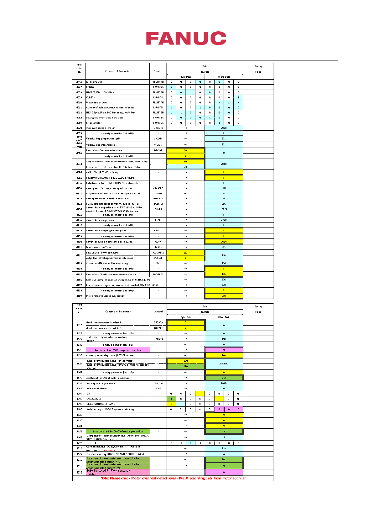
2. Spindle parameter setting
3rd Party motor parameter
Edit special calculated parameter for this 3
rd
party motor/amplifier combination
Page 4
3rd party Synchronous Spindle Motor Tuning
Page 4 of 42
Created at June,22 2017 by Frank Wittig
Page 5

3rd party Synchronous Spindle Motor Tuning
Page 5 of 42
Created at June,22 2017 by Frank Wittig
1
Please Set: P3454#4=1
Spindle N o.
IP Addres s
127.0.0.1
Path
1
Export to txt
Write to CN C
You could use SP_Synchron_Parameter_output.xlsm for cr eating parameter .tx t file or to r ead-in param eter
directly via FOCAS.
Page 6
3rd party Synchronous Spindle Motor Tuning
Page 6 of 42
Created at June,22 2017 by Frank Wittig
Parameters related to the SPEED:
Number of teeth
#2
#1
#0
Motor model
64
0 0 0
α i I0.5
128
0 0 1
α i I1- α i I 3
192
1 0 0
α i I6- α i I50 , α i I P12 -
α i IP60
384
1 0 1 512
0 1 1
Minimum clamp speed of spindle motor (M-series) P3735
Maximum clamp speed of spindle motor (M-series) P3736
(4096 means 100%)
Maximum spindle speed gear stage 1 P3741
gear stage 2 P3742
gear stage 3 P3743
gear stage 4 (T-series only) P3744
CTH1A CTH2A
Gear ratio SPINDLE - MOTOR stage 1: 0 0 P4056
stage 2: 0 1 P4057
stage 3: 1 0 P4058
stage 4: 1 1 P4059
Direction of Spindle and Motor rotation P4000#0
Parameters related to the MOTOR ENCODER:
Motor sensor type Connector #3 #2 #1 #0 P4010
αiM Sensor JYA2 0 0 0
αiMZ, αiBZ, αiCZ (analog) Sensor JYA2 0 0 1
αiCZ (serial) Sensor JYA3 0 1 1
3rd party sensor 1Vpp sine wave JYA2 1 1 0
A,B phase, sine wave Z phase
(αi BZ sensor Z phase compatible)
3rd party sensor 1Vpp sine wave JYA2 1 1 1
A,B phase, Driver type Z phase
Motor sensor mounting direction (normal/opposite direction) 0/1
also valid for sensor with Fanuc serial interface
Detection of one rotation signal less than 10 min
rd
If using this with 3
party sensor 1Vpp ➜ set 4010#2,#1,#0=1,1,1
Gear teeth number of motor sensor P4011
-1
P4394#2=1
Arbitrary number of speed feedback pulses P4334
Range: 32 to 32767 unit 1λ/rev
-16 to -32767 unit -2λ/rev
Example: When number of teeth is 36,000 λ/rev, it should be set to”-18,000”
Store AMR offset using 3rd party sensor with Fanuc serial interface (RCN…F) P4548#0=1
256 0 1 0
Page 7
3rd party Synchronous Spindle Motor Tuning
Page 7 of 42
Created at June,22 2017 by Frank Wittig
Number of teeth
#7
#6
#5
#4
64
0 1 0
1
128
0 0 0
1
256
0 0 0
0
384
1 1 0
0
512
0 1 0
0
1024
1 0 0
1
When motor sensor is used for pos. fb,
when α Position Coder S is used
Parameters related to the POSITION ENCODER:
Spindle sensor mounting direction P4001 #4
Spindle sensor type Connector #3 #2 #1 #0 P4002
Non (no position control is used) none 0 0 0 0
Motor sensor for position feedback JYA2 0 0 0 1
αi Position Coder JYA3 0 0 1 0
αi BZ or αi CZ (analog) Sensor
(*)
JYA4 0 0 1 1
αi CZ (serial) Sensor JYA3 0 1 1 0
α Position Coder S JYA4 0 1 0 0
3rd party sensor 1Vpp sine wave JYA4 1 1 0 1
A,B phase, sine wave Z phase
(αi BZ sensor Z phase compatible)
(*)
3rd party sensor 1Vpp sine wave JYA4 1 1 1 0
A,B phase, Driver type Z phase
Third party sensor square-wave JYA3 1 1 1 1
A,B phase, normal width
square phase Z phase
Third party sensor square-wave JYA3 1 1 0 0
A,B phase, narrow width
square-wave Z phase
Third party sensor FANUC serial α JYA3 0 1 0 1
interface 02 (Normal and High speed
two-pairs transmission)
Third party sensor FANUC serial JYA3 0 1 1 0
α i interface (High speed
one-pair transmission)
Detection of one rotation signal less than 10 min
If using this with Sensors (*) ➜ set 4010#3,#2,#1,#0=1,1,1,0
Gear teeth number of Position sensor P4003
-1
P4394#2=1
when α Position Coder is used,
Arbitrary number of position feedback pulses P4361
Range: 64 to 32767 unit 1λ/rev
-32 to -32767 unit -2λ/rev
0 0 0 0
Page 8
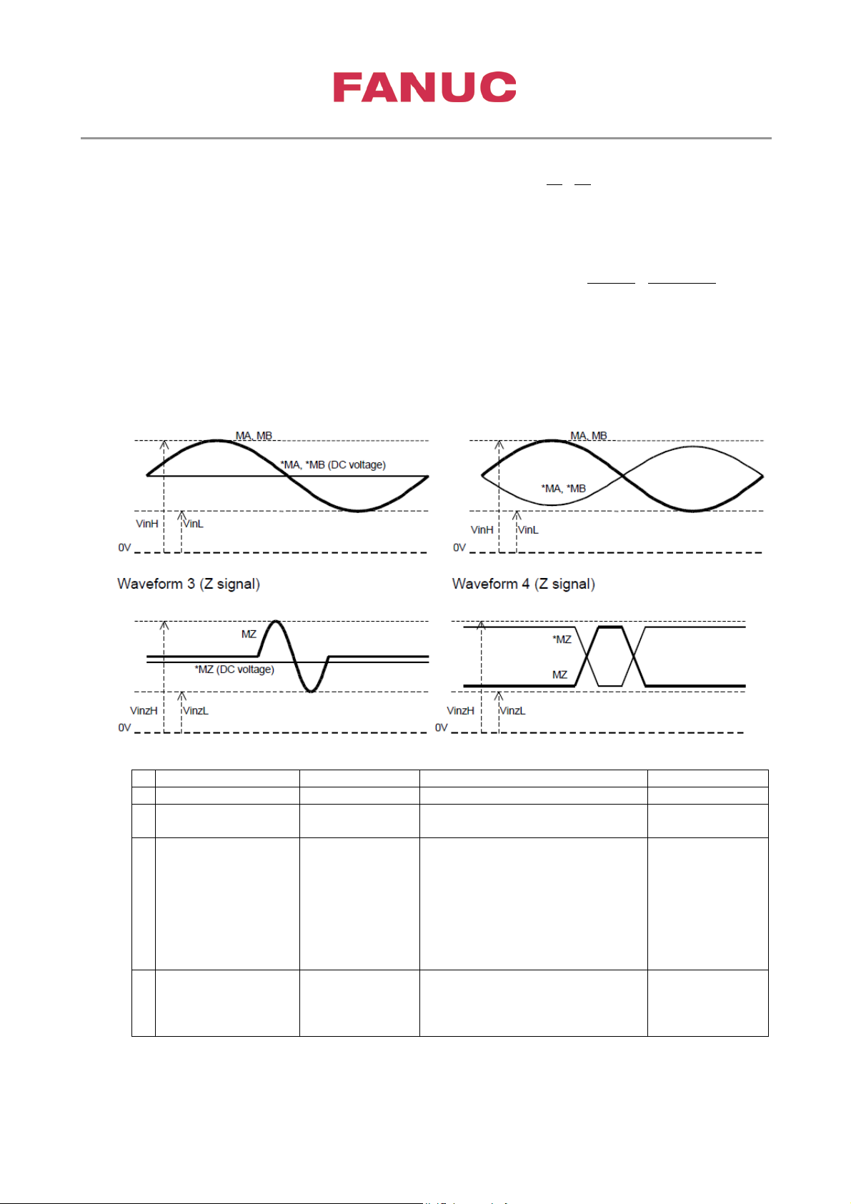
3rd party Synchronous Spindle Motor Tuning
Page 8 of 42
Created at June,22 2017 by Frank Wittig
Example: When number of teeth is 36,000 λ/rev, it should be set to”-18,000”
Symbol
Related check point
Value
1
Input impedance
Rin 100kΩMin.
2
Power supply to
sensor
Vcc (Vdd = 0V)
JYA2-pin9,18,20
JYA4-pin9,18,20
5Vdc±5%,
150mAMax
3
Input voltage
VinL
MA
JYA2-pin7, JYA4-pin8
VinH = 3.5V
4
Input voltage (MZ,
VinzL
MZ
JYA2-pin2, JYA4-pin2
VinzH = Vcc
#1 #0
Gear ratio between Spindle and Position Coder: x1 0 0 P3706
x2 0 1
x4 1 0
x8 1 1
Arbitrary gear ratio between Spindle and Position Coder Spindle Pos Coder
Number of teeth: (CTH1A=0) P4171 P4172
Number of teeth: (CTH1A=1) P4173 P4174
Sensor signal specification:
Signals for JYA2 and JYA4 input (A,B,Z unprocessed signals)
Waveform 1 (A, B signal) Waveform 2 (A, B signal)
(MA,*MA, MB, *MB)
*MZ)
VinH
VinzH
JYA2-pin5, JYA4-pin5
*MA
Max VinL = 1.5V
Min
JYA2-pin6, JYA4-pin6
MB
JYA2-pin7, JYA4-pin8
*MB
JYA2-pin1, JYA4-pin1
*MZ
Max VinzL = 0V
Min
Page 9
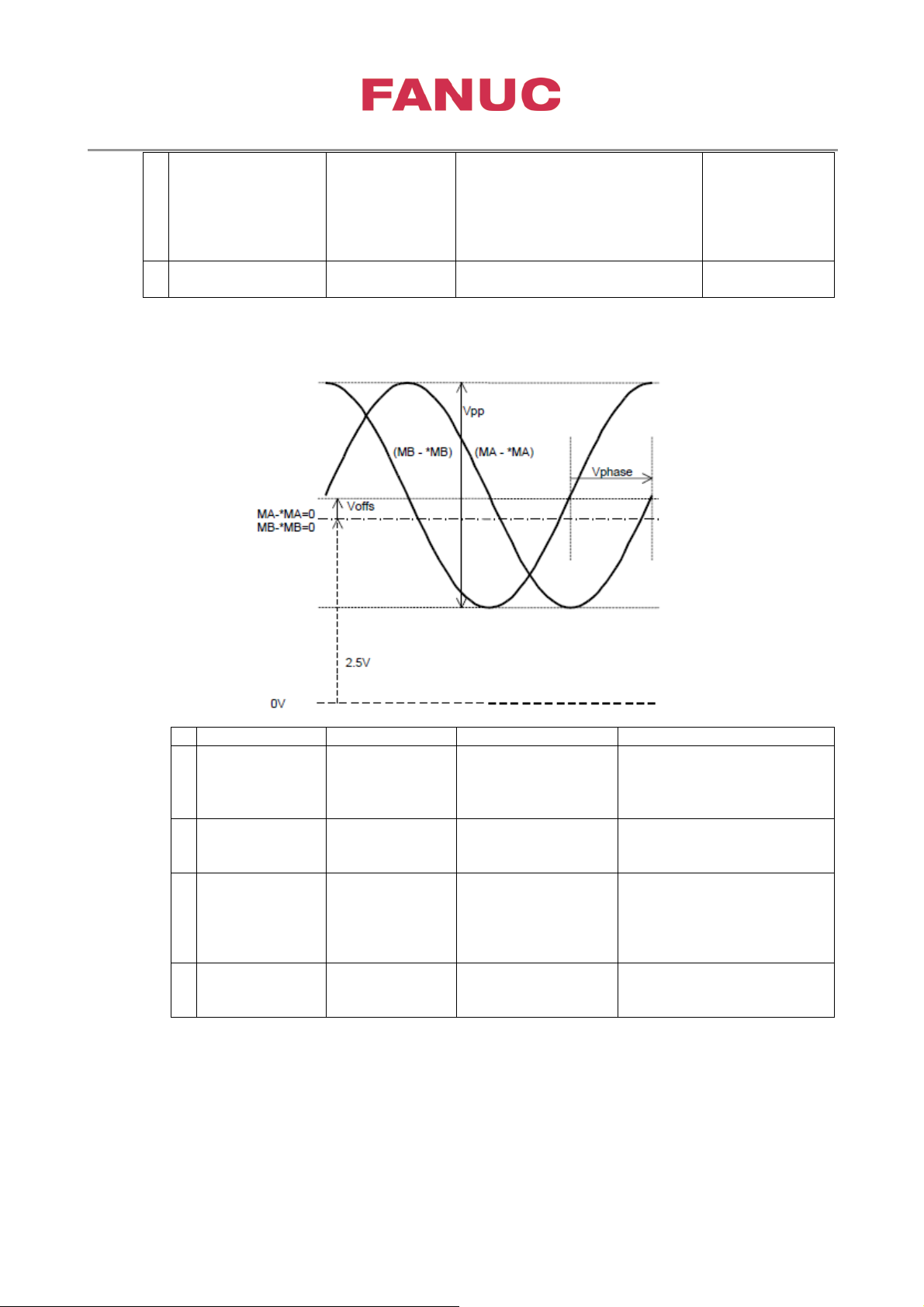
3rd party Synchronous Spindle Motor Tuning
Page 9 of 42
Created at June,22 2017 by Frank Wittig
5
Wave counts per
128∼32767
acceptable.)
6
Maximum frequency
Fmax
400kHz
Symbol
Related check point
Value
1
Signal
- *MB)
Vpp
(from JYA2)
PA2,PB2
0.60Vppmin, 1.2Vppmax
2
Signal Offset
- *MB)
Voffs
±100mVMax
3
Signal
(MB - *MB)
Vppdef
1.00±0.10Max
4
Phase Offset
MB - *MB)
Vphase
90±3deg
one revolution
• 1Vpp sine wave A,B phase (Differential signal)
sin/rev
32768∼65534
sin/rev (Only
even number is
Amplitude
(MA - *MA, MB
(MA - *MA, MB
Amplitude
Difference
(MA - *MA) /
(MA - *MA,
PA1,PB1
(from JYA4)
(include acceptable error)
Page 10
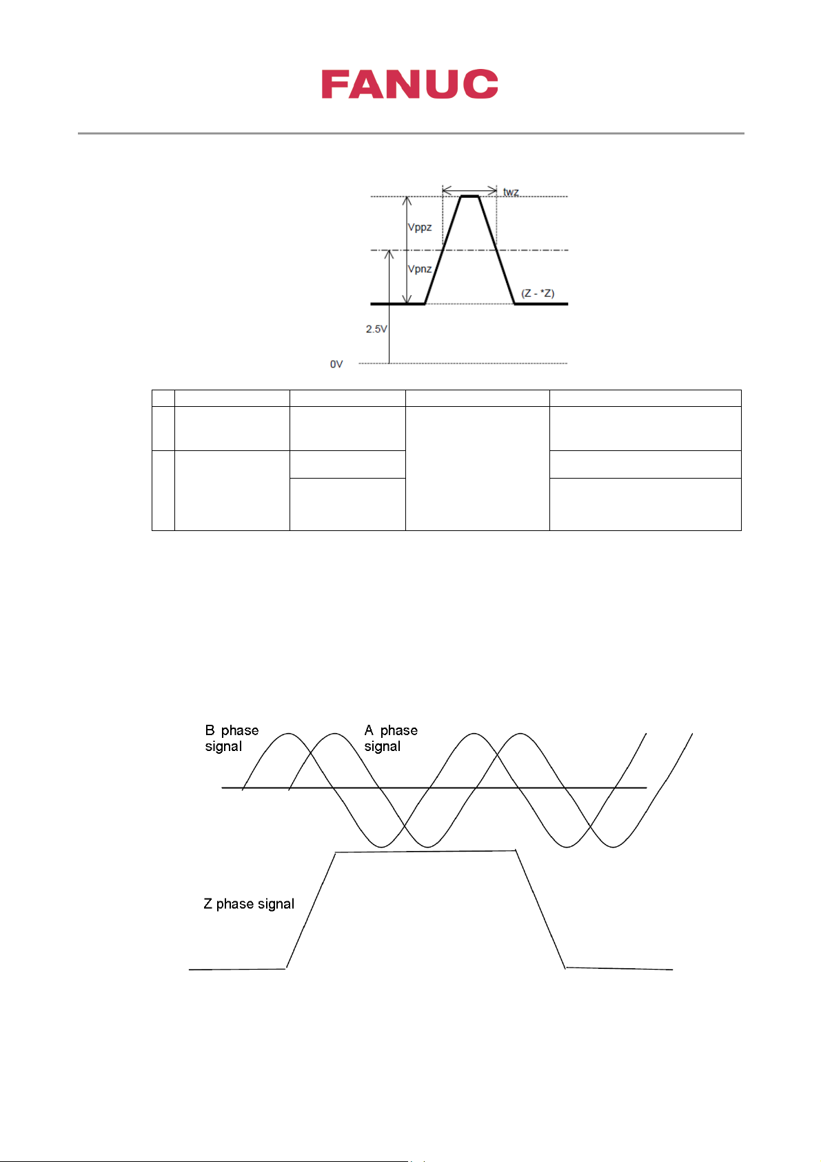
3rd party Synchronous Spindle Motor Tuning
Page 10 of 42
Created at June,22 2017 by Frank Wittig
Symbol
Check terminal
Value
1
Pulse Width
twz
(from JYA2)
2.5 μsec min
2
Signal
(MZ - *MZ)
Vppz
0.23Vmin
Vpnz
0.23Vmin
• Driver type Z pha se
(MZ - *MZ)
Amplitude of
Reference
signal
Note) There should be one Z phase signal per one rotation.
PS1
(from JYA4)
PS2
When a spindle sensor with distance-coded
reference mark is used, please refer to B-65280EN/08-26.
The following amplifier cannot be used with a spindle sensor with distance-co ded referen ce mar k.
iSVSP for 0i-D series: A06B-6164-Hxxx#H580
− β
iSP TYPE A: A06B-6141-Hxxx#H580, A06B-6151-Hxxx#H580
− α
iSP TYPE B: A06B-6142-Hxxx#H580, A06B-6152-Hxxx#H580
− α
Page 11
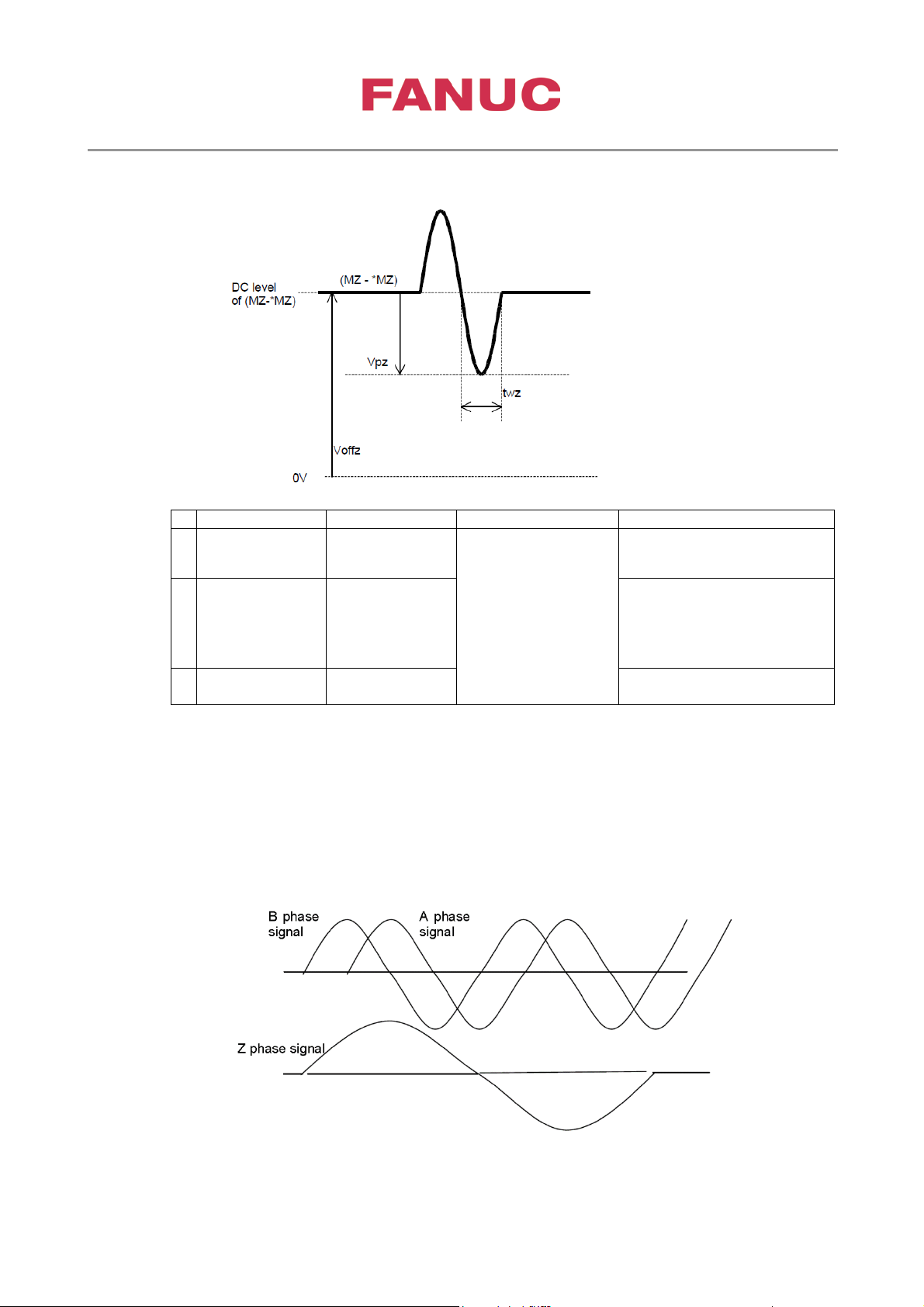
3rd party Synchronous Spindle Motor Tuning
Page 11 of 42
Created at June,22 2017 by Frank Wittig
Symbol
Check terminal
Value
1
Pulse Width
twz
(from JYA2)
2.5 μsec min
2
Signal
(MZ - *MZ)
Vpz
0.23Vmin
3
DC Signal
Offset (Z - *Z)
Voffz
3.5Vmax
2Vmin
• Sine wave signal Z phase (αiMZ, αiBZ sensor compatible: differential signal)
(MZ - *MZ)
Amplitude of
Reference
signal
Note)
PS1
(from JYA4)
PS2
Z phase signal is generated only one per rotation.
When a spindle sensor wit h dist ance-coded reference mark is used, please refer to B-65280EN/08-26.
The following amplifier cannot be used with a spindle sensor with distance-co ded referen ce mar k.
iSVSP for 0i-D series: A06B-6164-Hxxx#H580
− β
iSP TYPE A: A06B-6141-Hxxx#H580, A06B-6151-Hxxx#H580
− α
iSP TYPE B: A06B-6142-Hxxx#H580, A06B-6152-Hxxx#H580
− α
Page 12
3rd party Synchronous Spindle Motor Tuning
Page 12 of 42
Created at June,22 2017 by Frank Wittig
α
i
SP
α
i
SP
-B
α
i
SVP-B
β
i
SVSP
MA
*MA
MB,*MB
MZ,*MZ
Rt
Rt
Rt
Rt is defind in specification of 3rd party sensor.
3rd Party
Sensor
JYA2
or
JYA4
B phase
A phase
Z phase signal
Turn of A/B phase signals
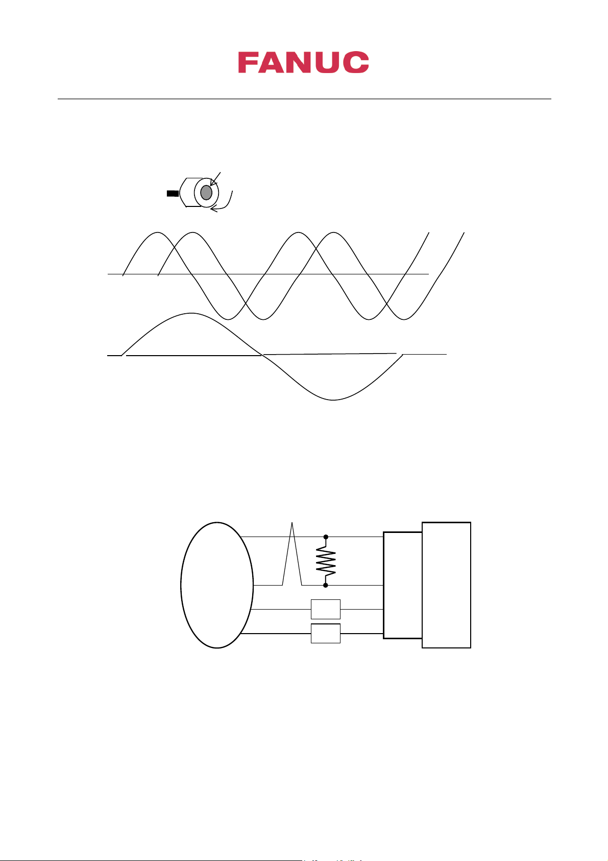
The relation between A/B phase signal and the direction of rotation is as follows.
Note) If the turn of A/B phase si gnals are the reverse, our circuit distinguishes CCW.
Gear of sensor
Direction of rotation
CW
Motor
signal
signal
Notes
A. αiSP, αiSP-B and βiSVSP do not include terminating resistor. Matchi ng of specification between
sensor outputs and αiSP, αiSP-B and β
iSVSP inputs should be considered terminating resistor. If
terminating resistor is required to match the input range (absolute value and differential value),
please insert it outside of the αiSP, αiSP-B and β
iSVSP.
Page 13
3rd party Synchronous Spindle Motor Tuning
Page 13 of 42
Created at June,22 2017 by Frank Wittig
Level-up αiSP-B
Level-up αiSVP-B
β
i
SVSP-B
MA
*MA
MB,*MB
MZ,*MZ
Rt
Rt is defind in specification of 3rd p ar t y sensor.
3rd Party
Sensor
JYA2
or
JYA4
Rt
Rt
No.4004#6(JYA2)
No.4004#7(JYA4)
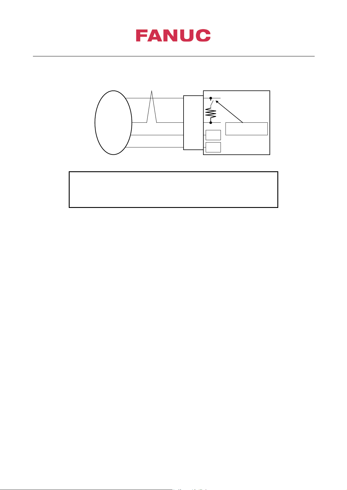
[JYA2] No.4004#6=0:(Disables 120Ω terminating resistor),
Level-up αiSP-B and Level-up αiSVP-B include a terminating resistor (120 Ω), and termina ting
resistors (120 Ω) can be set by using the f ollowing parameters.
[JYA4] No.4004#7=0:(Disables 120Ω terminating resistor),
No.4004#6=1:(Enables 120 Ω terminating resistor)
No.4004#7=1:(Enables 120 Ω terminating resistor)
B. Setting for reference signal.
When α
iMZ or αiBZ sensor compatible type is not used, please select driver t ype setting.
Page 14
3rd party Synchronous Spindle Motor Tuning
Page 14 of 42
Created at June,22 2017 by Frank Wittig
Symbol
Related check point
Value
1
Input impedance
Rin 150Ω typ.
2
Power supply to
sensor
Vcc
(Vdd = 0V)
JYA3-pin9,18,20
5Vdc±5%,
350mAMax
3
Input voltage of A,B
VinL
PAC
JYA3-pin8
VinH = 2.5V Min
4
A,B phase offset
PBC,*PBC)
Vphase
90±3deg
5
Input voltage of Z
VinzL
PSC
JYA3-pin2
VinH = 2.5V Min
with RS422)
6
Twz
JYA3-pin2
7
Wave counts per
128∼32767
acceptable.)
8
Maximum frequency
Fmax
400kHz
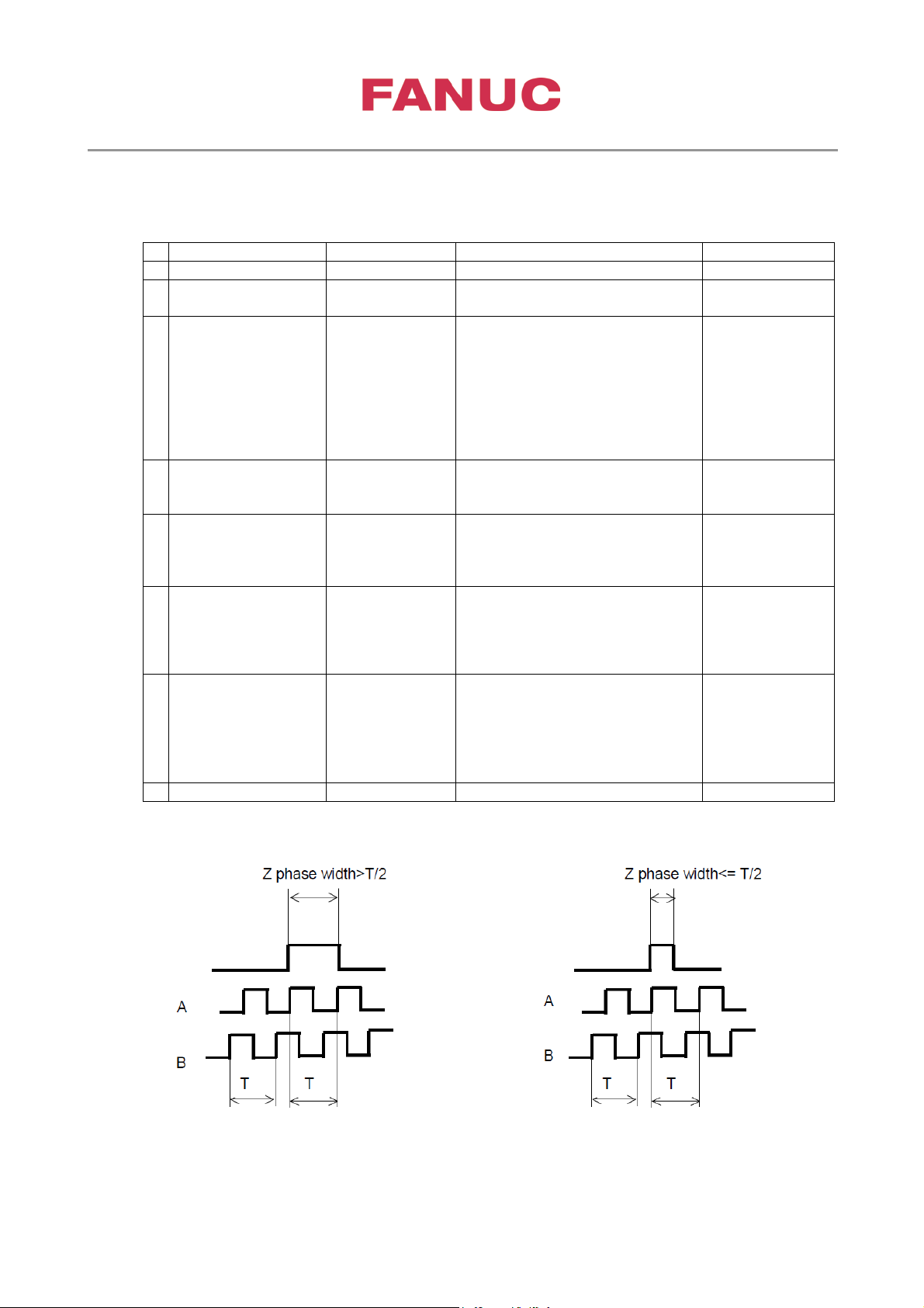
• Signals for JYA3 input
Square wave A,B,Z phase (unprocessed signals)
phase
(PAC,*PAC,
PBC,*PBC)
(PAC,*PAC,
phase
(PSC, *PSC)
Z phase width
(PSC, *PSC)
one revolution
VinH
VinzH
JYA3-pin5
*PAC
JYA3-pin6
PBC
JYA3-pin7
*PBC
JYA3-pin1
*PSC
PSC
JYA3-pin1
*PSC
VinL = 0.5V Max
(In accordance
with RS422)
VinL = 0.5V Max
(In accordance
2.5 micro sec
Min
cycle/rev
32768∼65534
cycle/rev (Only
even number is
normal width Z phase si gnal narrow width Z phase signal
Page 15
3rd party Synchronous Spindle Motor Tuning
Page 15 of 42
Created at June,22 2017 by Frank Wittig
No.4397
#4
Thermostat
0 0 0
FANUC standard
thermistor
degree C)
KTY84-130 (NXP)
(Note3)
≠0 (90 to 180
degree C)
Software edition
H(08) edition or later
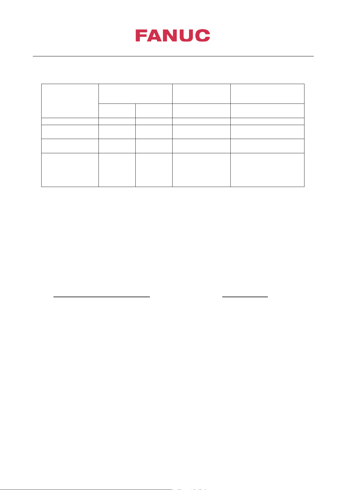
Parameter for thermal sensor to detect m oto r overheat
Thermal sensor t ype
Kind of sensor
selection
No.4587
0 0
1 0(or 1)
Pt1000(Hayashi)
(Note4)
(Note4)αiSP and β
Monitoring booth thermistor and thermostat simultaneously
When using αiSP amplifier for 30i-B series CNC to drive a motor which has a thermistor and a
thermostat for motor protection, it is possible to connect both thermo-sensors simultaneously for
motor overheat alarm (SP9001) detection.
αi SP amplifier (for 30i-B series CNC) Spindle Software:
A06B-6220-Hxxx#H600 9DA0/16(P) and later
A06B-6270-Hxxx#H600
A06B-6230-Hxxx#H600 (SVP)
Using either thermistor or thermostat for overheat alarm detection P4017#6 = 0
Using both thermistor and thermostat simultaneously for overheat P4017#6 = 1
alarm detection
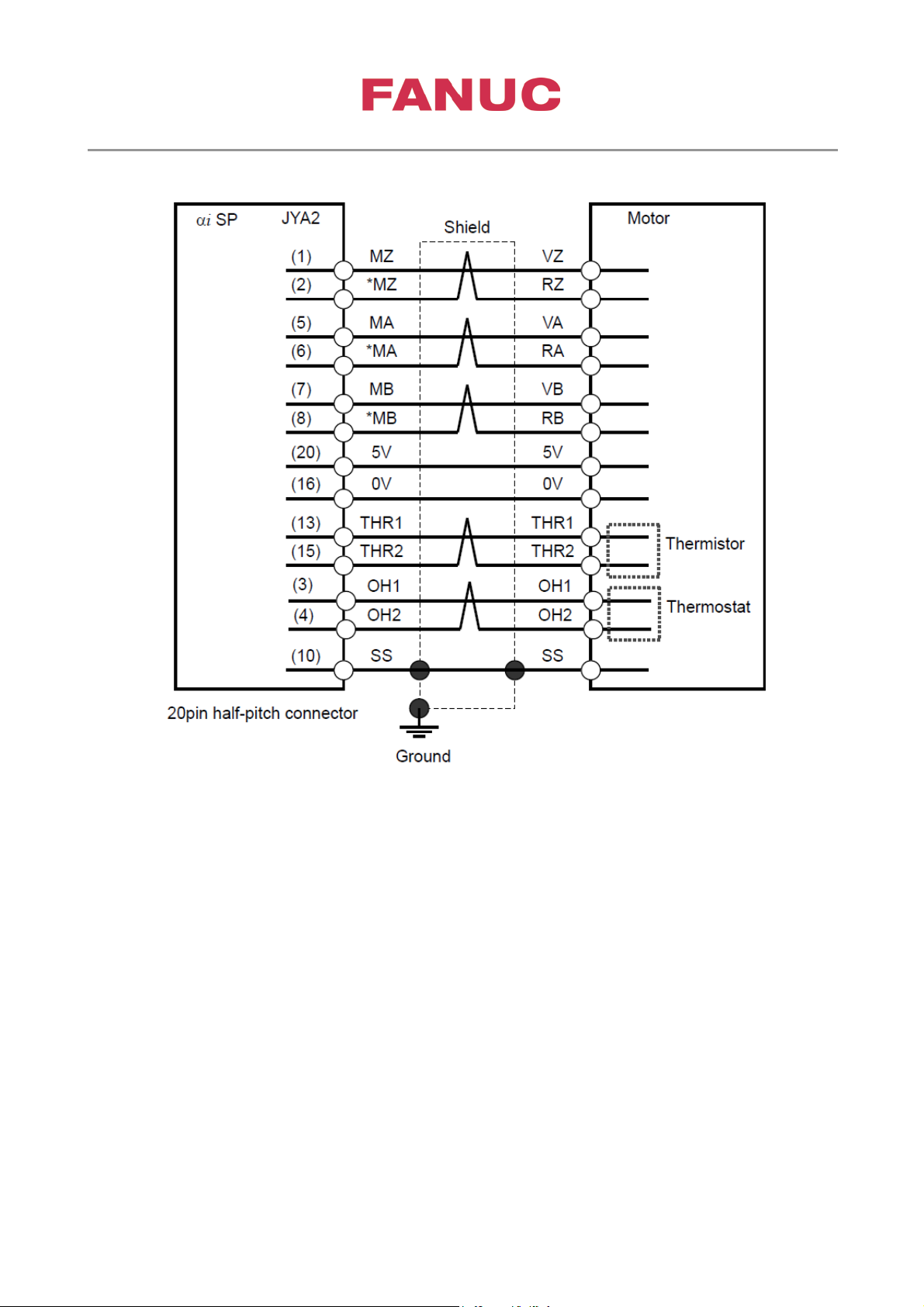
In case of using both thermistor and thermostat simultaneously for motor overheat protection,
thermistor should be connected with THR1 (13) and THR2 (15), and thermostat should be connected
with OH1 (3) and OH2 (4) as following diagram:
0 2
Setting for motor
overheat level
No.4134
≠0 (90 to 180
≠0 (1 to 180 degree
C)
(Note3) βiSVSP series is non-compliant.
9DAA series:
H(08) edition or later
9DB0 series:
iSVSP series are non-compliant.
Page 16
3rd party Synchronous Spindle Motor Tuning
Page 16 of 42
Created at June,22 2017 by Frank Wittig
A-97077E-015
Parameter when the External Reference Switch is u sed:
External one-rotation signal is used P4004 #2 = 1
External one-rotation signal type detects leading edge: #3=0 P4004 #3
detects trailing edge: #3=1
The motor sensor is used as position feedback P4002 #3 #2 #1 #0
0 0 0 1
Page 17
3rd party Synchronous Spindle Motor Tuning
Page 17 of 42
Created at June,22 2017 by Frank Wittig
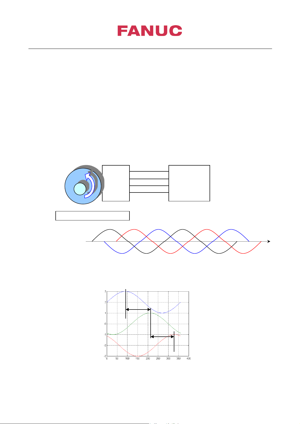
Back Electromotive Voltage
U-Phase
V-Phase
W-Phase
120degree
120degree
U
u αiSP
CCW
BackEMFphase order (CCW)
U V W
time
3. Test of motor rotation direction
Connect the oscilloscope to the motor power cables U, V and W.
Preferable would be the 3-channel type oscilloscope. If only 2-channel oscillos c op e
is available measure as follows:
Connect 2 power lines (U,V) each to 1 channel and use the 3 power line as star-point by connecting
booth ground pins of channel 1 and 2 with it. (W)
Measure the BEMF voltage during rot ati on.
When the motor is rotated to the direction CCW by viewing from the flange surface side, please
confirm that the back EMF of u, v and w go forward in turn. It is necessary to connect the power
cable as the follows according to this confirmation.
u, v, w order ----------------> connect u and U, v and V, w and W
V
W
GND
v
w
GND
Page 18
3rd party Synchronous Spindle Motor Tuning
Page 18 of 42
Created at June,22 2017 by Frank Wittig
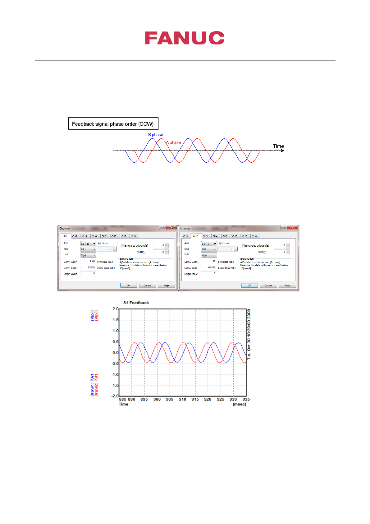
The velocity feedback cable sensor connected to JYA2 on αiSP. When the motor is rotated to
the direction CCW by viewing from the flange surface side, the feedback signal A/B phases are
displayed as the following chart.
Turn motor manually and measure A and B phase using Servo guide.
If phase sequence is reversed, please swap motor V - W phase. Alternatively change P4010#3=1.
Remark: PA1, PB1 isn’t possible to measure with serial encoder.
Page 19

3rd party Synchronous Spindle Motor Tuning
Page 19 of 42
Created at June,22 2017 by Frank Wittig
4. Tuning current loop
Parameter setting for preparation
Parameter setting
P4007#7 = 0 : SFR/SRV signal is used as a signal to start pole detection.
P4008#6 = 1: One-rotation signal of motor sensor is not used a s a r eference of pole position.
P4083 = 15000: Constant current O N/OFF function is availa ble
= 15000: 50% of maximum current is set as step current.
P4395#3 = 1: Parameter transferred from CNC becomes immediately act iv e.
P4536 = 3265(2369): Q-axis current command ( I Q C M D ) is out put.
P4537 = 0
P4538 = 3278(2382): Q-axis current feedback ( IQAX I S ) is out put .
P4539 = 0
The setting of P4536 & P4538 depend on the version of spindle software. If the
spindle software is older version than 9D80/D (9D53/K, 9D70/J), the numerical value
of parenthesis must be set.
* Restore setting of all these parameter after measuring.
Program
: Shift pulse is “0” ( 1 word data )
: Shift pulse is “0” ( 1 word data )
Prepare following CNC pr ogr am to measure step response of excitation current.
G10L52 (L50 for CNC 16i, 18i, 21i)
N4397 P1 R01000000 : funct ion bit ON for clear memory
G11
G10L52 (L50)
N4397 P1 R11000000 : tr igger on ( st or e st ep response data to internal memory)
G11
G4 X0.1 : dwell
S0 M3 : enables excitation w ith S0 – current step ON (che ck also aiSP display in case of
problems)
G4 X1.0 : dwell (1sec)
M05
N1 G10 L52 (L50):
N4397 P1 R00000000 : funct ion bit off
G11
N999 M30
1 Programmable data input function (CNC option) is required to use G10.
*
2 Parameter P4397#7,#6 is av ailable 9D50/K (9D70/ B) or lat er .
*
*
If KTY thermal sensor is applied ➜ N4397 P1 Rxxx10000
3
Page 20
3rd party Synchronous Spindle Motor Tuning
Page 20 of 42
Created at June,22 2017 by Frank Wittig
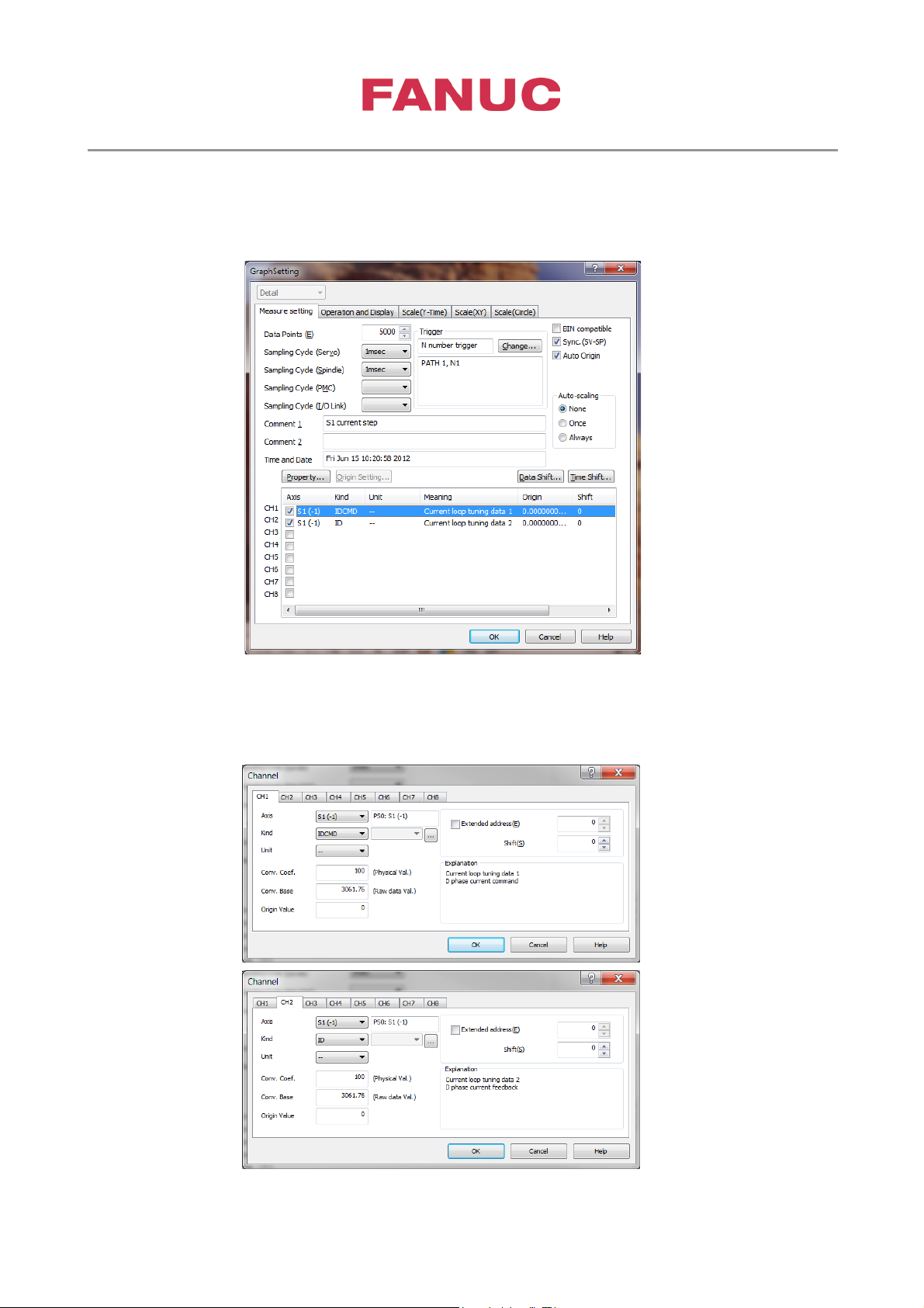
SERVO GUIDE setting
Set following data from Graph w indow → Setup(s) → Channel(F9).
Data Points : 5000
Trigger Path/Seq.No. : 1
Select Axis “Sx” (x=1,2,…) and set fo ll ow in g data.
Kind : IDCMD for CH1, ID for CH2
Conv. Coef. : 100 for CH1 and CH2
Conv. Base : 1024*P4111/100 for CH1 and CH2
Remark: current loop tun i ng should be done before pole detection is performed!
Page 21
3rd party Synchronous Spindle Motor Tuning
Page 21 of 42
Created at June,22 2017 by Frank Wittig
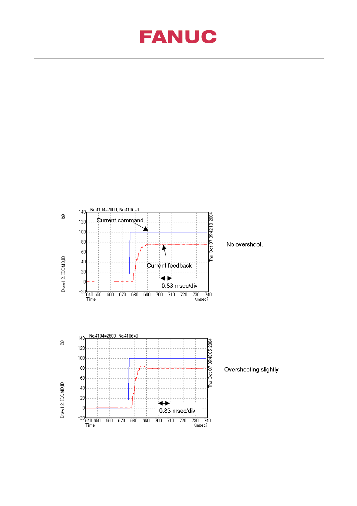
Gain tuning procedure
• Set initial current loop gain as follows.
proportional gain : P4104=2000
integral gain :
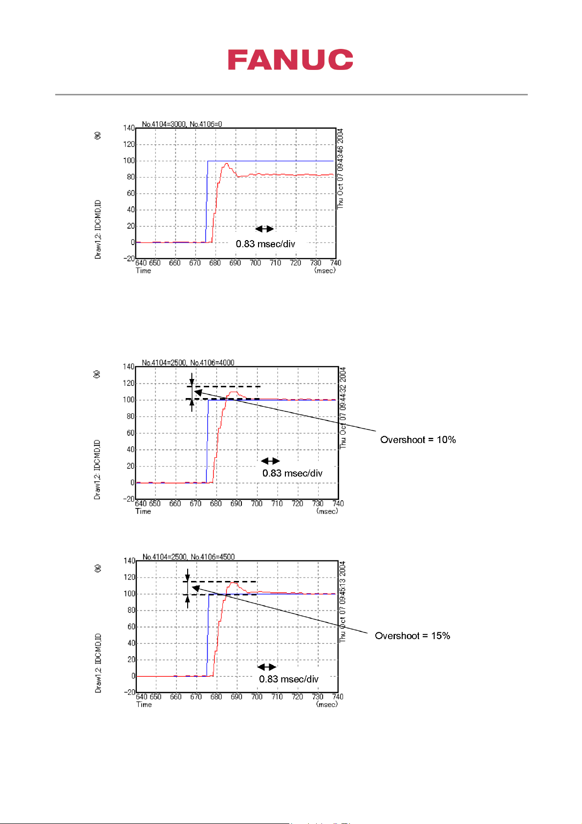
• Raise proportional gain P4104 until overshoot occurs.
• Raise integral gain P4106 until quantity of over shoot become 15%.
Tuning example
Current loop proportional gain = 2000, cur rent lo op int egr al gain = 0
Current loop proportional gain = 2500, cur rent lo op int egr al gain = 0
P4106=0
Page 22
3rd party Synchronous Spindle Motor Tuning
Page 22 of 42
Created at June,22 2017 by Frank Wittig
Current loop proportional gain = 3000, cur rent lo op int egr al gain = 0
► Tuning value of current loop proportional gain is 2500
Current loop proportional gain = 2500, cur rent lo op int egr al gain = 4000
Current loop proportional gain = 2500, cur rent lo op int egr al gain = 4500
► Tuning value of current loop integral gain is 4500
Page 23
3rd party Synchronous Spindle Motor Tuning
Page 23 of 42
Created at June,22 2017 by Frank Wittig
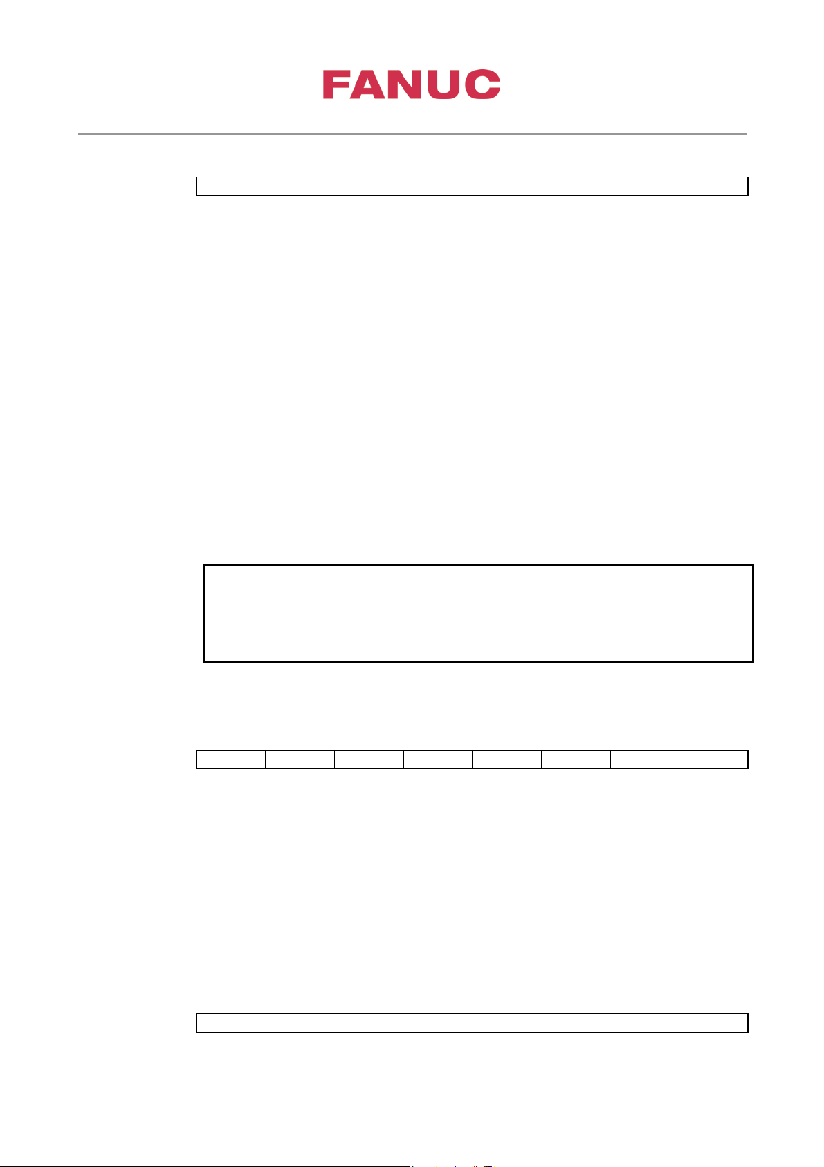
5. Pole det ection
0i
30i
#7
#6
#5
#4
#3
#2
#1
#0
4007
4007
EPFSIG
0i
30i
4083
4083
Current ratio/motor stop confirmation time in pole position detection operation
NOTE
this parameter needs to be adjusted.
0i
30i
#7
#6
#5
#4
#3
#2
#1
#0
4398
4398
SELMET
5.1. Parameter settings
5.1.1. Parameters related to pole position detection
EPFSIG Selects a pole position detection start signal.
0 : Uses SFR or SRV as a pole position detection start signal.
1 : Uses EPFSTR as a pole position de tection start signal.
Set this parameter to select a desired start signal.
The upper two digits (thousands and hundreds) indicate a current ratio in pole position
detection, and the lower two digits (tens and ones) ind icate a motor stop conf irmation time.
Current ratio in pole position detection (upper two digits)
Unit of data : 1%
Valid data range : 0 to 99
Initial setting : Depends on the motor model.
Set the magnitude of a current command value in pole position detection operation as a
ratio to the maximum current value.
This parameter is valid in the minute moving method or DC current method.
Motor stop confirmation time (lower two digits)
Unit of data : 0.1sec
Valid data range : 0 to 99
Initial setting : Depends on the motor model.
Set a period of time for confirming the stop of the motor in DC current method.
If pole detection position precision is insufficient for a cause such
as friction, the motor output torque may decrease. In such a case,
SELMET Selects a pole position detection method.
0 : Performs pole position detection in the DC current method.
1 : Performs pole position detection in the mi nute moving method + stop method (auto
select), or in the minute moving method.
Normally, set 1 (auto select or minute moving method).
Page 24
3rd party Synchronous Spindle Motor Tuning
Page 24 of 42
Created at June,22 2017 by Frank Wittig
NOTE
or later, and 9DB0 series A (01) edition or later.
0i
30i
#7
#6
#5
#4
#3
#2
#1
#0
4399
4399
MINUTE
NOTE
or later, and 9DB0 series A (01) edition or later.
0i
30i
4449
4449
Direction detection current(Current value B)/polarity determination current(Current value C)
NOTE
or later, and 9DB0 series A (01) edition or later.
This parameter is valid with 9D53 series C (03) edition or later,
9D70 series B (02) edition or later, 9D80 series B (02) edition or
later, 9D90 series A (01) edition or later, 9DA0 series A (01) edition
MINUTE Selects a pole position detection method.
0 : Minute moving method + stop method (auto select)
1 : Minute moving method
Usually, set this parameter to 1 (minute moving method) to use the function.
This parameter is valid with 9D53 series I (09) edition or later,
9D70 series H (08) edition or later, 9D80 series B (02) edition or
later, 9D90 series A (01) edition or later, 9DA0 series A (01) edition
The upper three digits (ten thousands, thousands, and hundreds) indicate a direction
detection current, and the lower two dig its (tens and ones) indicate a polarity de termination
current.
Direction detection current (upper three digits)
Unit of data : 1%
Valid data range : 0 to 320
Initial setting : 0
Set a current for pole position direction detection in pole position detection operation.
When 0 is set, 100% is set.
This parameter is valid in the stop method.
Polarity determination current (lower two digits)
Unit of data : 1%
Valid data range : 0 to 99
Initial setting : 0
Set a detection current for determining the polarity of the pole position as a ratio to the
maximum current value. When 0 is set, 70% is set internally.
This parameter is valid in the stop method.
This parameter is valid with 9D53 series C (03) edition or later,
9D70 series B (02) edition or later, 9D80 series B (02) edition or
later, 9D90 series A (01) edition or later, 9DA0 series A (01) edition
Page 25
3rd party Synchronous Spindle Motor Tuning
Page 25 of 42
Created at June,22 2017 by Frank Wittig
0i
30i
4450
4450
Travel distance allowance magnification/velocity feedback threshold
NOTE
or later, and 9DB0 series A (01) edition or later.
0i
30i
#7
#6
#5
#4
#3
#2
#1
#0
4008
4008
NEGREF
0i
30i
4084
4084
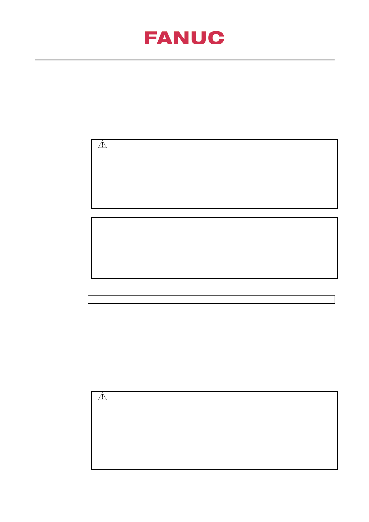
AMR offset
The upper three digits (ten t housands, thousands, and hundreds) indicate a travel distance
allowance magnification, and the lower two digits (tens and ones) indicate a velocity
feedback threshold.
Travel distance allowance magnification (upper three digits)
Unit of data : 1%
Valid data range : 0 to 200
Initial setting : 0
Set a travel distance allowance magnification. Set a ratio relat ive to a machine angle of 5
deg assumed to be 100%. When 0 is set, 100% (machine angle of 5 deg) is set internally.
This parameter is valid in the minute moving method.
Velocity feedback threshold (lower two digits)
Unit of data : 1%
Valid data range : 0 to 99
Initial setting : 0
Set a velocity feedback threshold for determining the stop of the motor, assuming 100% =
110 min
-1
. When 0 is set, 10% (11 min-1) is set internally.
This parameter is valid in the minute moving method.
This parameter is valid with 9D53 series C (03) edition or later,
9D70 series B (02) edition or later, 9D80 series B (02) edition or
later, 9D90 series A (01) edition or later, 9DA0 series A (01) edition
5.1.2. Parameters related to AMR offset
NEGREF Sets whether to use a one-rotation signal of the motor sensor as reference pole position
data.
0 : Uses the one-rotation signal position of the motor sensor as reference pole position
data.
1 : Does not use the one-rotation signal position of the motor sensor as re ference pole
position data.
When this parameter is set to “1,” the spindle amplifier operates based on the initial pole
position detected by pole position detection operation regardless of the one-rotation signal
position of the motor sensor.
Usually, set this parameter to 0 (use s the AMR offse t function) to use the spindle a mplifier.
Page 26
3rd party Synchronous Spindle Motor Tuning
Page 26 of 42
Created at June,22 2017 by Frank Wittig
Unit of data : 1 pulse (8192 pulses = electric angle 360 deg)
CAUTION
the AMR offset again.
NOTE
set this parameter to 0.
0i
30i
4085
4085
CAUTION
4 Turn the power off, then on again.
Valid data range : 0, 1 to 8192
Initial setting : 0
Set an AMR offset.
This parameter is valid when bi t 6 (NEGREF) of para meter No. 4008 is set to 0. Set an
adjustment value to this parameter. When this parameter is set to 0, the AMR offset
function is disabled. When setting 0 pulse as an AMR offset, set 8192.
See Subsection 1.5.3, “AMR Offset Func tion”, in Part IV, and adjust this parameter for
each motor.
1 This parameter needs to be adjusted for individual motors. If
parameters for another machine are loaded, clear and adjust this
parameter after loading the parameters.
2 This parameter indicates the phase relationships between the
motor and motor sensor. After the phase relationships are changed
due to a cause such as the replacement of the motor sensor, adjust
1 This parameter is valid with 9D53 series C (03) edition or later,
9D70 series B (02) edition or later, 9D80 series B (02) edition or
later, 9D90 series A (01) edition or later, 9DA0 series A (01) edition
or later, and 9DB0 series A (01) edition or later.
2 When the spindle software edition is earlier than the editions above,
AMR offset adjustment value
Unit of data : 1 pulse (8192 pulses = electric angle 360 deg)
Valid data range : -300 to +300 (electric angle: -13.2deg to +13.2deg)
Initial setting : 0
This parameter is used to adjust the AMR offset. The pole position can be shifted by the
specified number of pulses.
After execution of the AMR offset, check the torque command and actual speed during
forward rotation/backward rotation at the same speed, and adjus t this value so that the sam e
acceleration time and de celera tion tim e are achieved b y the sam e torque comm and and th at
the torque commands during constant rotation are almost the same.
1 After the adjustment with this parameter, change the following
parameters in the emergency stop state:
2 Add the adjusted value of parameter No. 4085 to the setting of
parameter No. 4084, and set the obtained value for parameter No.
4084 as the new AMR offset value.
3 After setting parameter No. 4084 again, set parameter No. 4085 to
"0".
Page 27
3rd party Synchronous Spindle Motor Tuning
Page 27 of 42
Created at June,22 2017 by Frank Wittig
NOTE
set this parameter to 0.
0i
30i
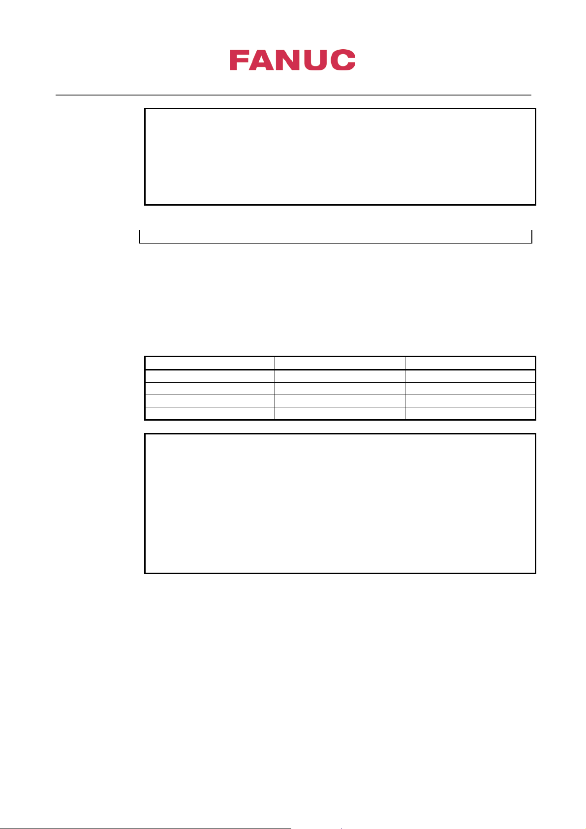
4532
4532
Arbitrary data output function number
Diagnosis No. (0i-D)
Diagnosis No. (30i)
1st spindle
720
720
2nd spindle
721
720
3rd spindle
740
720
4th spindle
741
720
NOTE
FS32i /320i /320is-A : G201 series F (6.0) edition or later
1 This parameter is valid with 9D53 series C (03) edition or later,
9D70 series B (02) edition or later, 9D80 series B (02) edition or
later, 9D90 series A (01) edition or later, 9DA0 series A (01) edition
or later, and 9DB0 series A (01) edition or later.
2 When the spindle software edition is earlier than the editions above,
Unit of data :
Valid data range : 0 to 32767
Initial setting : 0
Set this parameter to 2 when an AMR offset candidate value is to be checked on the
diagnosis screen of the CNC. An AMR offset candidate value (pole position correspond ing
to a one-rotation signal position counted relative to the pole detection position) can be
checked with the following numbers on the diagnosis screen of the CNC:
1 When this function is used, the following combinations of spindle
software and CNC software must be used:
For spindle software 9D70 series E edition or later and 9D80 series
B edition or later
FS30i /300i /300is-A : G002/G012/G022 series F (6.0) edi ti o n
FS31i /310i /310is-A5 : G121/G131 series F (6.0) edition or later
FS31i /310i /310is-A : G101/G111 series F (6.0) edition or later
or later
Page 28
3rd party Synchronous Spindle Motor Tuning
Page 28 of 42
Created at June,22 2017 by Frank Wittig
0i
30i
#7
#6
#5
#4
#3
#2
#1
#0
1st-
G070
G070 MRDYA
SFRA
SRVA
2nd-
G074
G074 MRDYB
SFRB
SRVB
1st-
G071
G071 *ESPA
2nd-
G075
G075 *ESPB
1st-
G073
G073 EPFSTRA
MPOFA
2nd-
G077
G077 EPFSTRB
MPOFB
0i
30i
#7
#6
#5
#4
#3
#2
#1
#0
1st-
F048
F048 EPFIXA
2nd-
F052
F052 EPFIXB
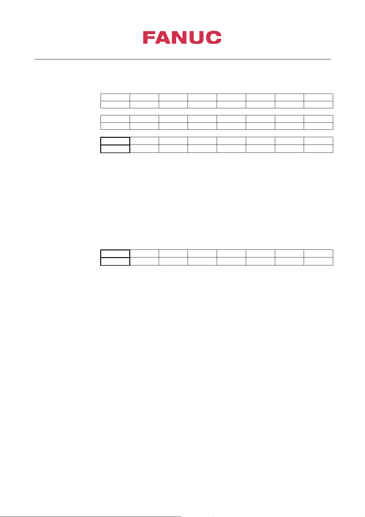
5.2. I/O Signals
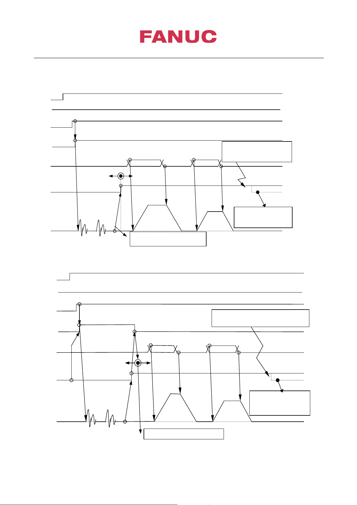
Pole position detection operation start signal (EPFSTRA)
(1) When bit 7 (EPFSIG) of parameter No. 4007 is set to 0:
This signal is disabled. Always set this signal to “0.”
(2) When bit 7 (EPFSIG) of parameter No. 4007 is set to 1:
To make the operator concerned with pole position detection operation, this signal can be used
together with EPFIX (pole position detection state signal). While this signal is input, the spindle
software ignores a command and displays error 30 (on the spindle amplifier (SP)). So, when EPFIX
is set to 1, turn this sig nal off.
Pole position detection state signal (EPFIXA)
This signal indicates the state of pole position detection.
0 : Pole position undetected
In this state, pole position detection operation is started by a start signal.
1 : Pole position detection completed
This signal is reset to 0 if a spindle alarm indicating the loss of the pole position due to trouble such
as a motor sensor disconnection is issued.
If this signal state is indicated using a lamp on the operator’s panel, the operator can recognize the pole
position detection state.
If any of the following spindle alarms is issued, t he sp indle am plifier (SP) loses the pole position and turns
off the pole position detection state signal (EPFIX = 0).
Spindle alarm Nos. : 01, 24, 25, 26, 31, 37, 65, 73, 90, 91, 92, 132, 133, 134, 139, 140, 141, 142
Page 29
3rd party Synchronous Spindle Motor Tuning
Page 29 of 42
Created at June,22 2017 by Frank Wittig
Pole position undetected state
The speed command is ignored.
Motor speed
Pole position 0 deg
Position movement
Power-on
MRDY
& *ESP
SFR/SRV
Speed command
EPFIX
Pole position detection completed state
The speed command is accepted.
The pole position is lost, so
that the speed command is
ignored.
Pole position
detection completed
MPOF=0
& EPFSTR=0
1)
2)
3)
4)
6)
5)
An alarm causing the
pole position
to be lost is issued, resulting in
EPFIX = 0.
Pole position 90 deg
Position movement
The pole position is lost, so
that the speed command is
ignored.
Pole position
undetected state
The speed
command is
ignored.
EPFSTR
Power-on
MRDY
& *ESP
& SFR/SRV
Speed command
EPFIX
Motor speed
Pole position detection completed state
The speed command is accepted.
Pole position detection completed
An alarm causing the pole position to be lost
is issued, resulting in EPFIX = 0.
MPOF=0
1)
2)
3)
4)
5)
6)
7)
Pole position 0 deg
Position movement
Pole position 90 deg
Position movement
5.3. Pole det e ction sequence
When SFR or SRV is used as a start signal (Parameter No.4007#7:EPFSIG=0)
When EPFSTR is used as a start signal (Parameter No.4007#7:EPFSIG=1)
Page 30
3rd party Synchronous Spindle Motor Tuning
Page 30 of 42
Created at June,22 2017 by Frank Wittig
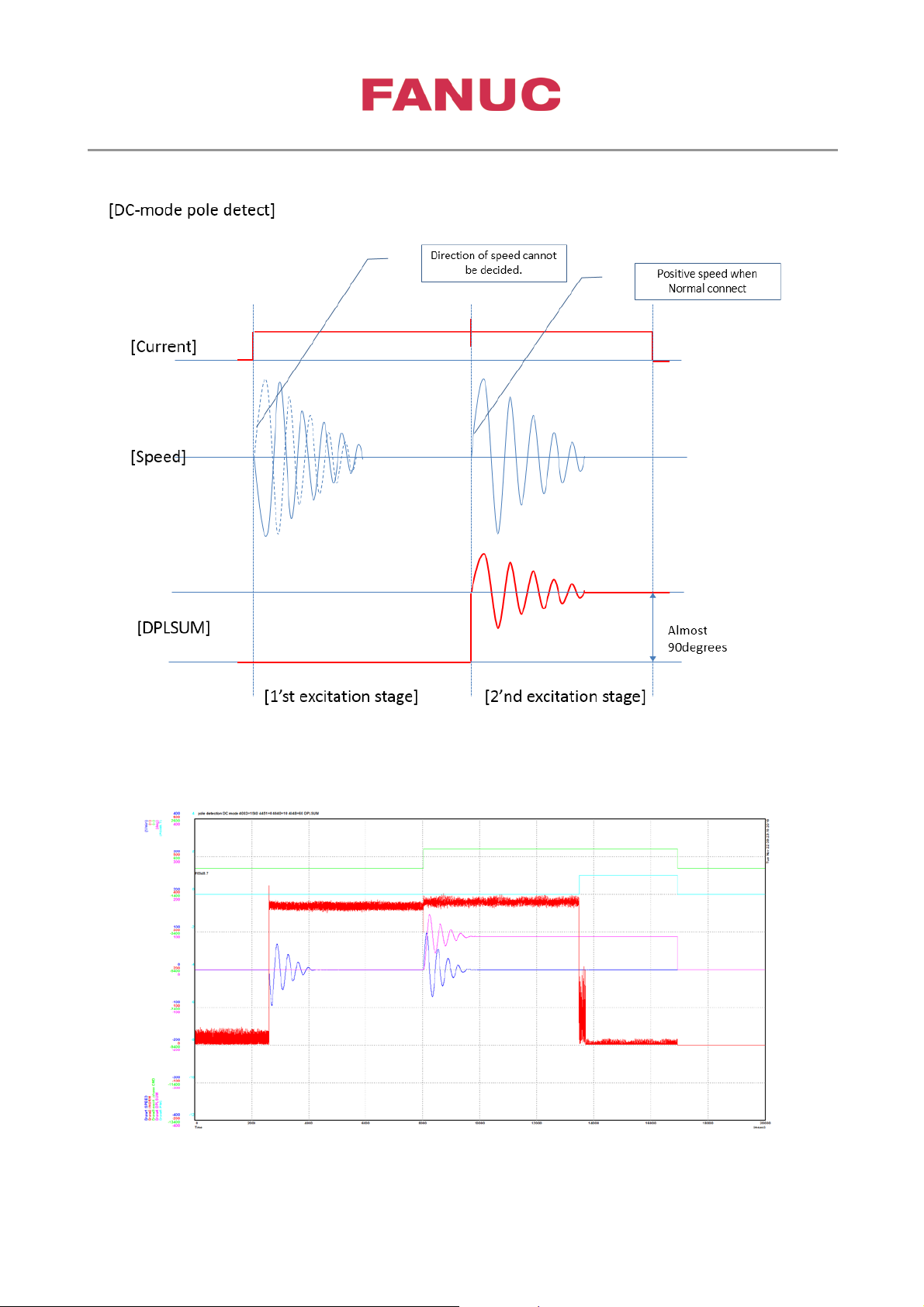
5.4. Vali da ti on of pol e detec t ion
Speed direction of first excitation should be opposite to speed direction of second excitation. If DPLSUM is
about 90 deg – pole detection is correct performed.
If speed direction is the same for first and second excitation – swap power phases V and W or better change
encoder counting direction by P4010#3=1.
Page 31
3rd party Synchronous Spindle Motor Tuning
Page 31 of 42
Created at June,22 2017 by Frank Wittig
Kind
Unit
Conv.Coef.
Conv.Base
Origin
Value
Extended
address
Shift
CH1
SPEED
1/min
1 1 0 0 -12
CH2
TCMD
%
100
16384
0 0 0
CH3
ARB(VDAXIS)
-
100
2309
0
3292
0
CH4
ARB(VQAXIS)
-
100
2309
0
3293
0
DPLSUM excitati on phas e CMD
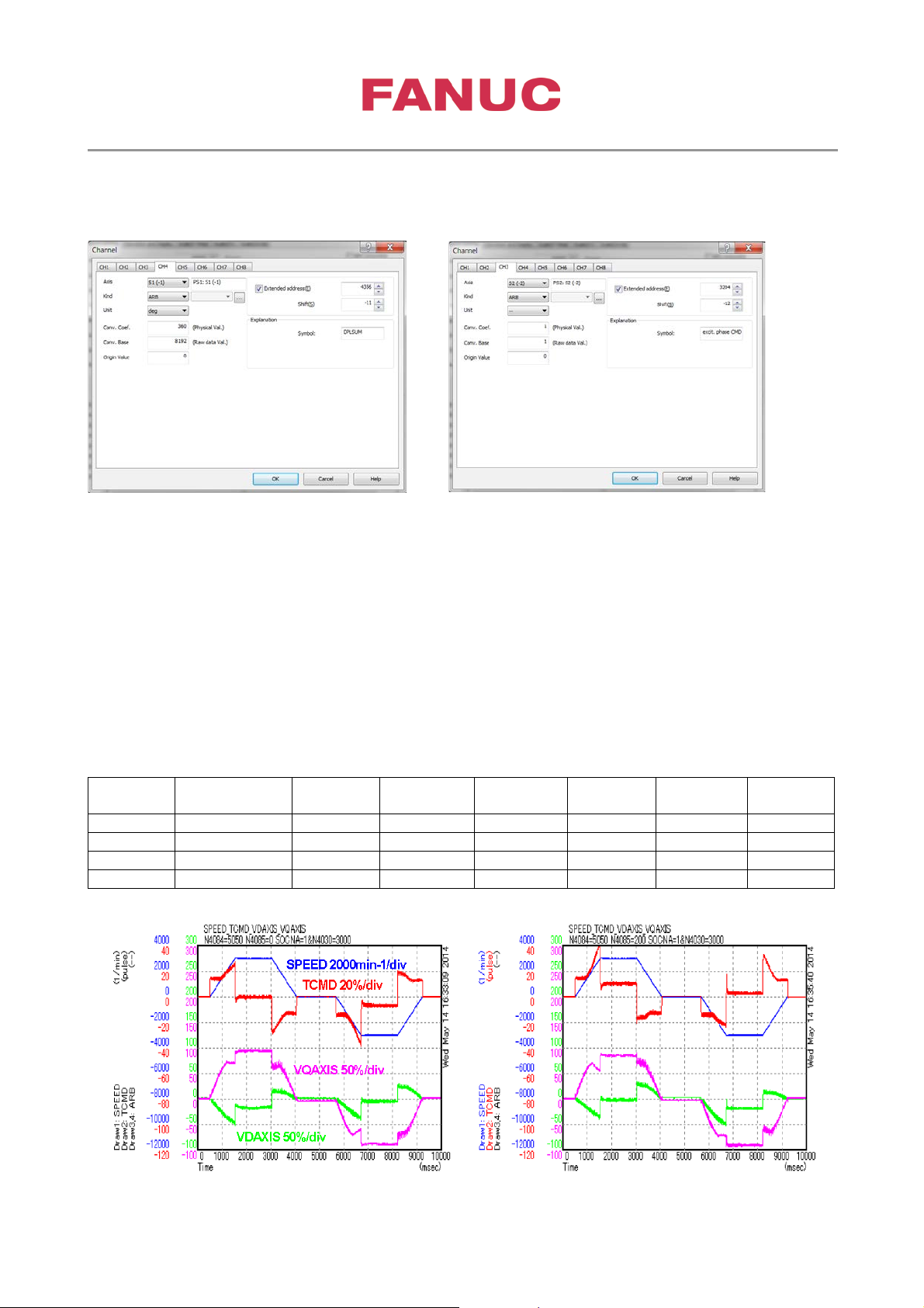
Check and Tuning of AMR offset
This is an example how AMR offset P4084 is adjusted by using the parameter P4085 for fine-tuning.
AMR offset is executed only one time after the pole detection. Therefore, if AMR-offset is adjusted only by
P4084, many times of pole detection is necessary. This required always Power OFF/ON.
For this reason, P4085 for fine-tuning at start-up could be used. After we perform fine-tuning of
AMR-offset by the N4085, we replace AMR-offset parameter N4084 by the value N4084+N4085 and
reset N4085 to 0.
Accelerate spindle if possible to maximum speed. In case of problems because Id current isn’t optimized
accelerate at least up to base speed.
Measure the following signals:
Page 32
3rd party Synchronous Spindle Motor Tuning
Page 32 of 42
Created at June,22 2017 by Frank Wittig
Kind
Unit
Conv.Coef.
Conv.Base
Origin
Value
Extended
address
Shift
CH1
SPEED
1/min
1 1 0 0 -12
CH2
ARB (VQAXIS)
-
100
2309
0
3293
0
CH3
ARB(IDAXIS)
-
64*Ga
1024*P4110
0
3277
0
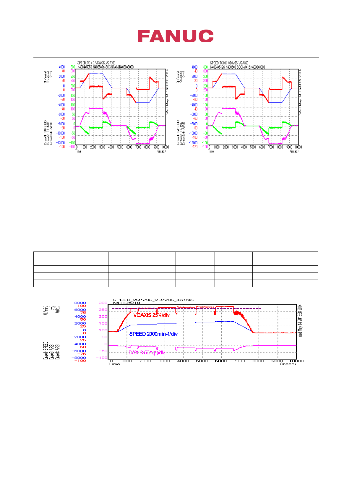
Adjust P4085 to confirm TCMD, VDAXIS and VQAXIS becomes symmetrical in +/- direction.
5.5. Tuning of d-axis current Id
5.5.1. Optimization of short circuit current
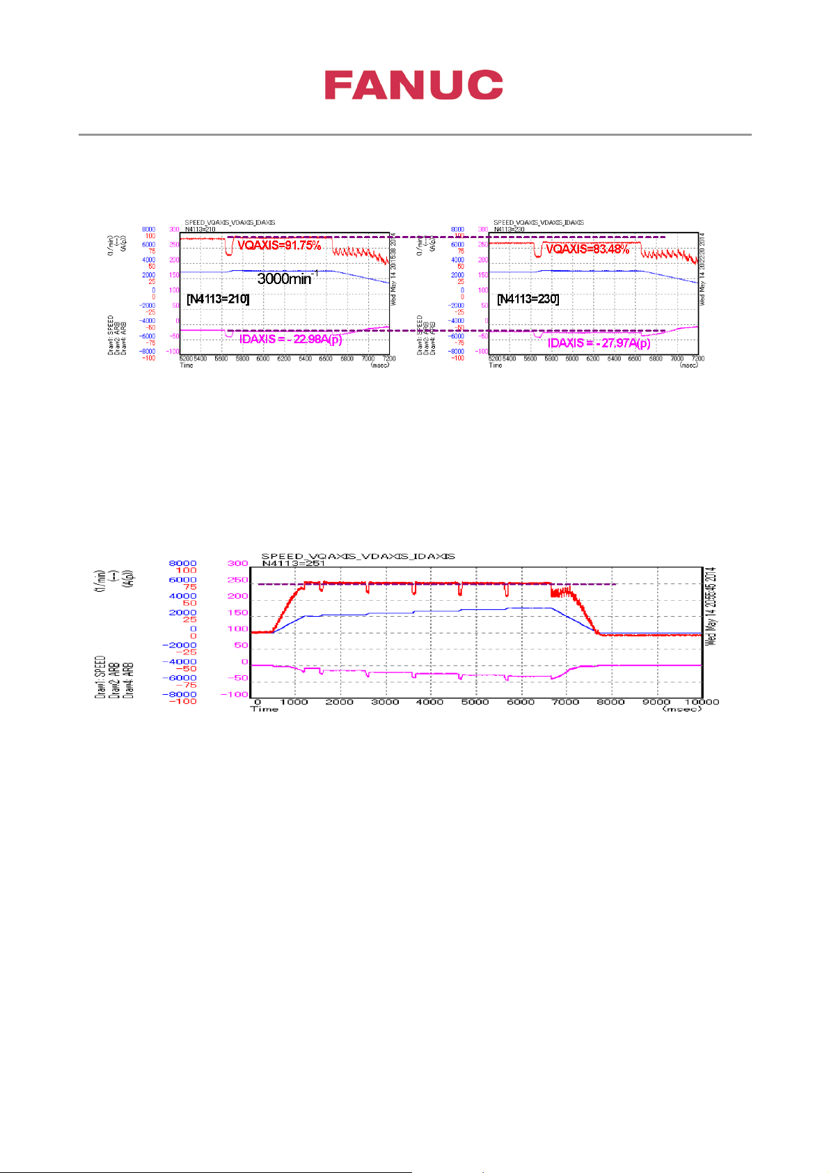
Short circuit current parameter P4113 could be calculated b y measuring VQ AXIS and IDAX IS with diff erent
setting in P4113 at same speed. Accelerate the motor in steps from base speed to maximum speed.
Measure the following signals:
Increasing of VQAXIS at higher speed indicates too low value in P4113.
Page 33
3rd party Synchronous Spindle Motor Tuning
Page 33 of 42
Created at June,22 2017 by Frank Wittig
By the two different setting of N4113 (=210, =230), the q-axis voltage command VQAXIS and the
d-axis current IDAXIS at the maximum speed 3000min-1 were the next values.
The short circuit current can be calculated as follows by the measurement values. In addition,
the maximum current is 70Arms, and the parameter N4111 is 317.
(φ/Ld) =(Id1 - (Vq1/Vq2)*Id2) / ((Vq1/Vq2) - 1)
=(-22.98 + (91.75/83.48)*27.97) / ((91.75/83.48) - 1)=78.34Ap → 55.39Arms
N4113 =N4111 * (55.39 / 70) = 317 * (55.39 / 70) = 251
By this tuning, VQAXIS became almost the same amplitude regardless of the speed
Page 34
3rd party Synchronous Spindle Motor Tuning
Page 34 of 42
Created at June,22 2017 by Frank Wittig
Kind
Unit
Conv.Coef.
Conv.Base
Origin
Value
Extended
address
Shift
CH1
SPEED
1/min
1 1 0 0 -12
CH2
ARB (VCMLMT)
-
100
2309
0
3300
0
CH3
ARB(IDAXIS)
-
64*Ga
1024*P4110
0
3277
0
5.5.2. Determination of inductance ratio Lq/Ld P4086
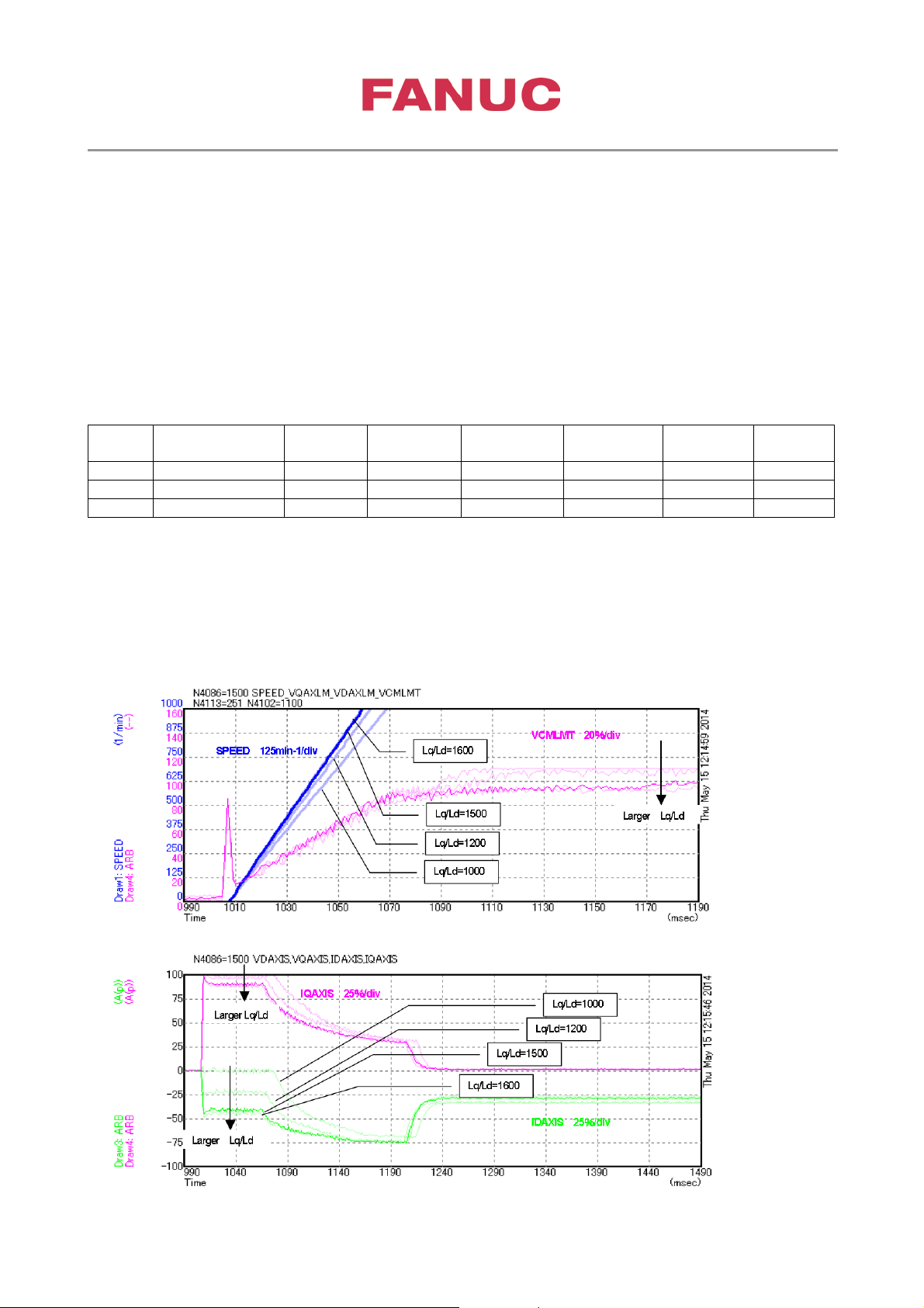
Inductance ratio depends on magnet design of rotor. Usually IPM (interior permanent magnet) types showing
bigger inductance r ati on t h an SP M ( sur f ac e permanent magnet) types. Inductance r ati on def in es if additional
reluctance torque is valid.
To optimize P4086 accelerate the motor up to base speed P4102 and check the setting in P4086 for achieving
shortest acceleration time.
If the acceleration time is almost same even if you change the parameter of inductance ratio, select the
small inductance ratio so that d-axis current becomes smaller.
Tuning example:
Measure the following signals:
When the inductance ratio N4086 was changed to 1000, 1200, 1500 and 1600, please compare
each acceleration time from 0 to 1000min-1 (less than base-speed N4102=1100).
The difference between the acceleration time in N4086=1500 and the acceleration time in
N4086=1600 is almost 0. The smaller N4086 is, the smaller d-phase current is. Therefore, “1500”
was chosen as the tuning value of N4086.
Page 35
3rd party Synchronous Spindle Motor Tuning
Page 35 of 42
Created at June,22 2017 by Frank Wittig
Kind
Unit
Conv.Coef
Conv.Base
Origin
Extende
address
Shift
CH1
SPEED
1/min
1 1 0 0 -12
CH2
ARB (VCMLMT)
-
100
2309
0
3300
0
CH3
ARB(ICMNRM)
-
64*Ga
1024*P4110
0
3280
0
CH4
ARB(INORM)
-
64*Ga
1024*P4110
0
3279
0
Kind
Unit
Conv.Coef
Conv.Base
Origin
Extende
address
Shift
CH1
ARB(VDCMD)
-
100
2309
0
3296
0
CH2
ARB(VQCMD)
-
100
2309
0
3297
0
CH3
ARB(IDAXIS)
-
64*Ga
1024*P4110
0
3277
0
CH4
ARB(IQAXIS)
-
64*Ga
1024*P4110
0
3278
0
5.5.3. Setup of base speed with maximum load P4102 and switching speed of current pattern P4103
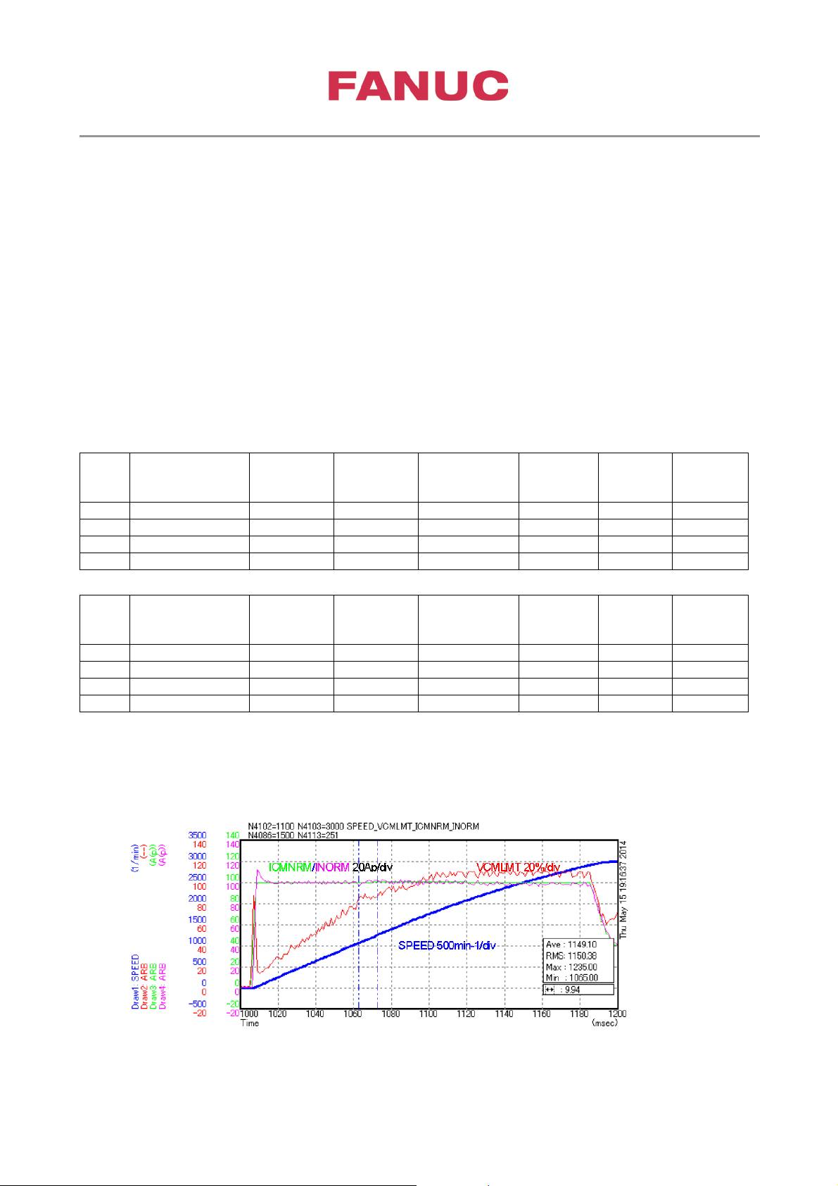
Observing the voltage command in acceleration up to the maximum speed, decide P4102 so that the
voltage command is not limited and becomes as higher level as possible. (If the voltage is limited, the
current deviation becomes large and the stability of the control decrease.)
Regarding P4103, select the smaller value than the speed value where q-axis voltage command cross
the level 0 in the higher speed than the base speed P4102. This is to prevent excessive magnetic field
weakening.
Higher P4102 means higher speed start point of Id current. So check VCMLMT which indicates speed
stability but consider also lower P4102 means larger Id current at high speed which causes more heat
generation.
Measure the following signals:
.
.
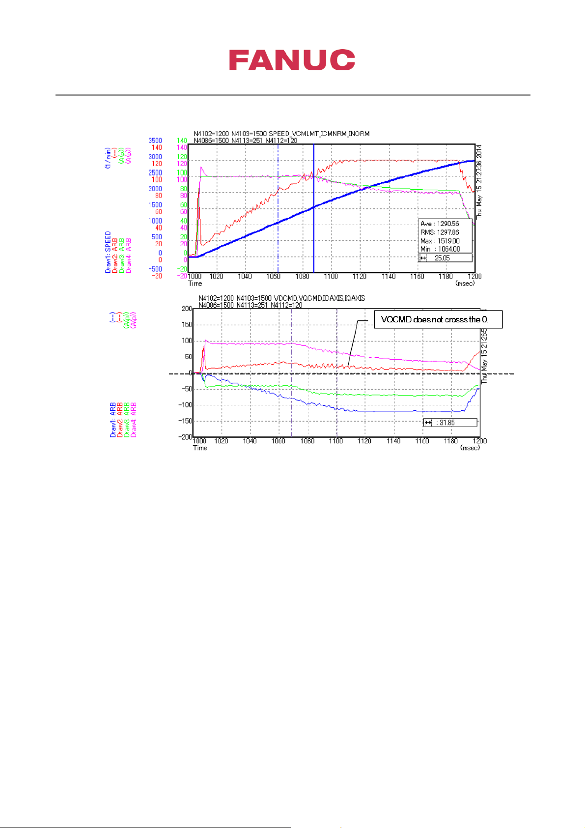
Observe the waveform during acceleration, with the setting of (P4102, P4103)=(1100,3000).
The voltage command VCMLMT is the level of over the 80% at the base speed 1100. As this
voltage level is low, it is necessary to change P4102 so that the voltage command VCMLMT
becomes the level from 90 to 100%.
Value
Value
d
d
Page 36
3rd party Synchronous Spindle Motor Tuning
Page 36 of 42
Created at June,22 2017 by Frank Wittig
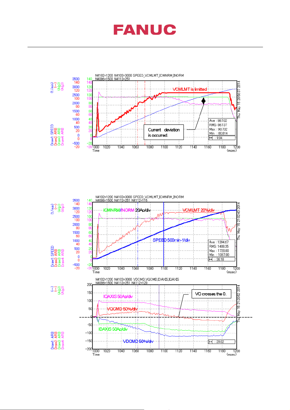
As the result that the base speed P4102 was changed from 1100 to 1200min-1, the following
waveform was got. The voltage command VCMLMT became to 90%, but the big current
deviation occurred b y limiting of voltage in the hi gh speed ar ea.
The current deviation at the high speed area became smaller by changing of P4112 (110→120).
But the q-axis voltage VQCMD crosses the level 0. This shows the magnetic field weakening is
excessive. (P4112 is normal 110. If increase P4112, please set P4112 less than 120.)
Page 37
3rd party Synchronous Spindle Motor Tuning
Page 37 of 42
Created at June,22 2017 by Frank Wittig
Change P4103 (P4103=3000→1500) to avoid the excessive magnetic field weakening at the
high speed. The q-axis voltage became not to cross the level 0 by this tuning.
Page 38
3rd party Synchronous Spindle Motor Tuning
Page 38 of 42
Created at June,22 2017 by Frank Wittig
Kind
Unit
Conv.Coef
Conv.Base
Origin
Extende
address
Shift
CH1
SPEED
1/min
1 1 0 0 -12
CH2
ARB (VCMLMT)
-
100
2309
0
3300
0
CH3
ARB(ICMNRM)
-
64*Ga
1024*P4110
0
3280
0
CH4
ARB(INORM)
-
64*Ga
1024*P4110
0
3279
0
5.5.4. Limit of regeneration power
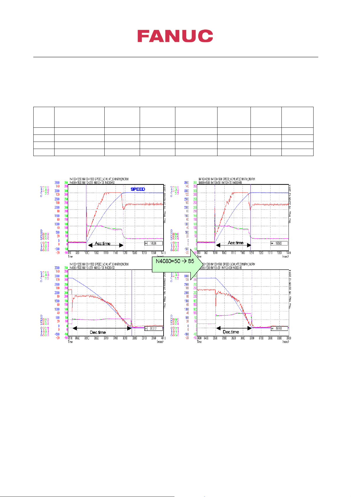
Perform the acceleration and deceleration up to the maximum speed, and adjust N4080 so that the
deceleration time becomes the same like acceleration time.
Measure the following signals:
.
Value
d
Page 39
3rd party Synchronous Spindle Motor Tuning
Page 39 of 42
Created at June,22 2017 by Frank Wittig
6. Optimization of Velocity loop
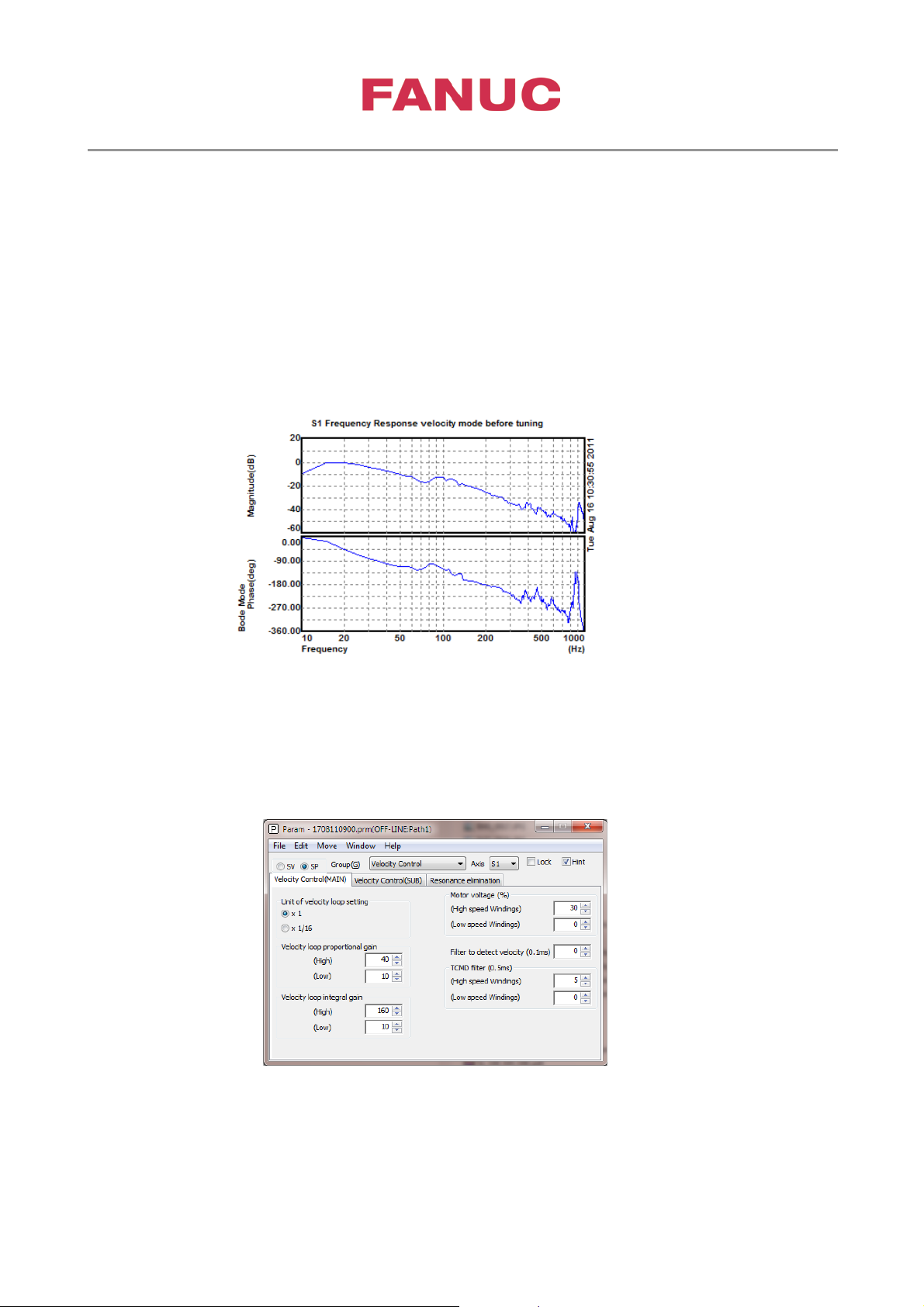
Velocity loop tuning using Servo guide Bode diagram
Graph window ➜ Tool ➜ Spindle tuning ➜ Frequency response measurement
or Navigator ➜ Filter Tuning (Spindle)
Note: MRDY needs to be ON for spindle frequency response measurement
Tuning of velocity gains
velocity loop proportional gain P4040
velocity loop integral gain P4048
Try to apply a Gain ratio P/I of 1/4 ➜ 1/6
Page 40
3rd party Synchronous Spindle Motor Tuning
Page 40 of 42
Created at June,22 2017 by Frank Wittig
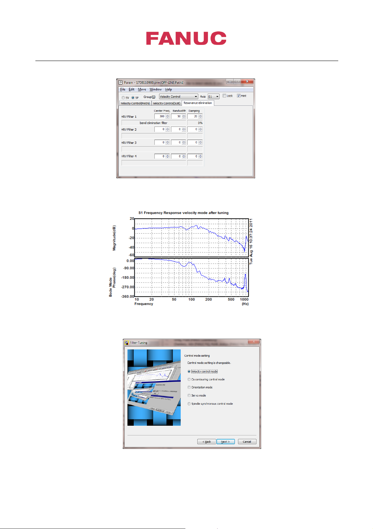
In case of resonance frequencies adopt resonance elimination filter
Result after tuning
If needed tune velocity loop also in other spindle mode
Page 41
3rd party Synchronous Spindle Motor Tuning
Page 41 of 42
Created at June,22 2017 by Frank Wittig
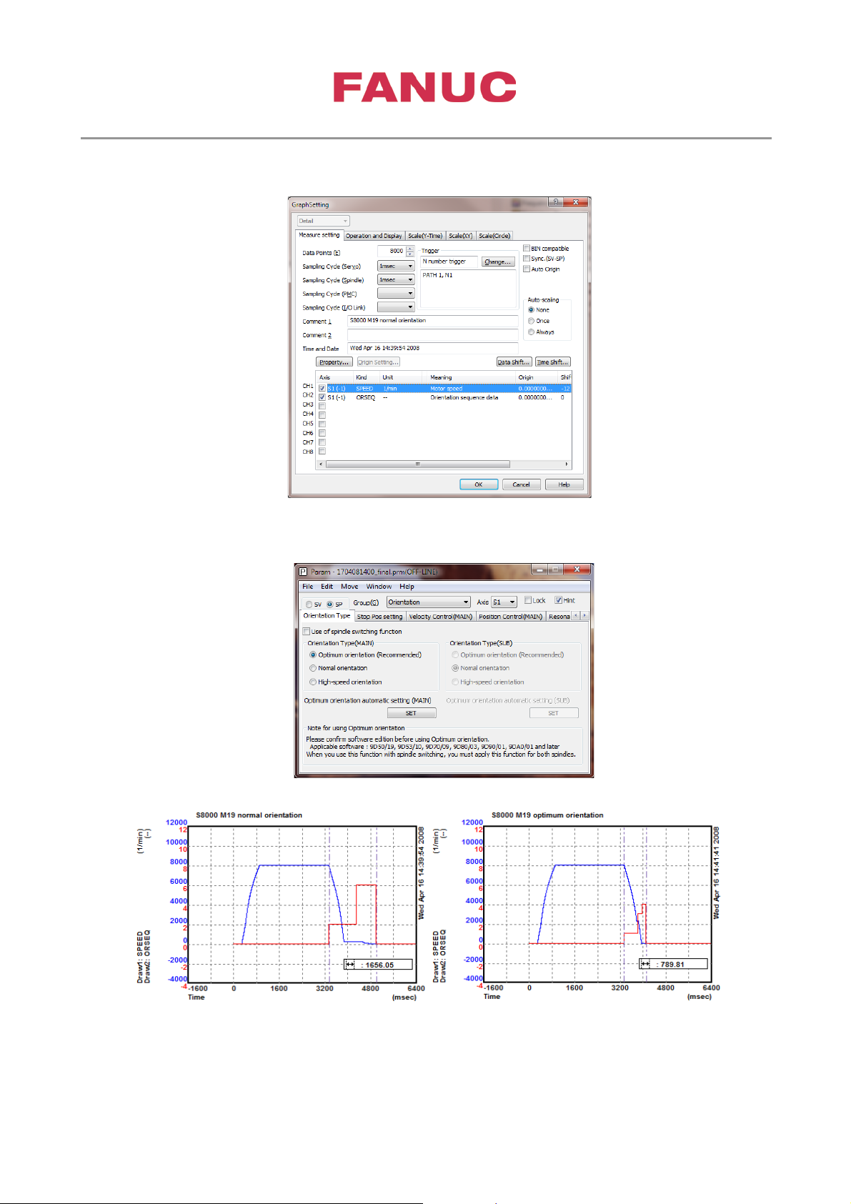
7. Adjustment of spindle orientation
Apply Optimum orientation
Normal orientation - t
= 1.656s Optimum orientation - t
orient
= 0.789s
orient
Page 42
3rd party Synchronous Spindle Motor Tuning
Page 42 of 42
Created at June,22 2017 by Frank Wittig
Appendix
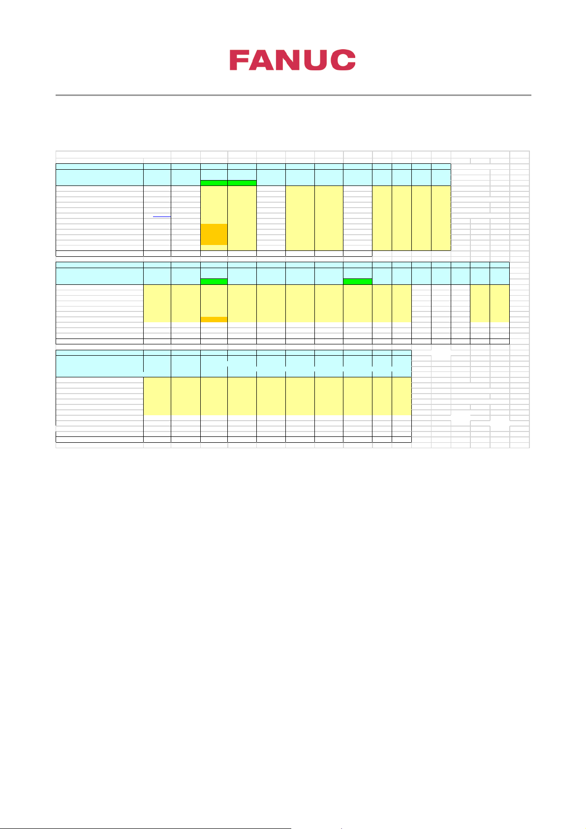
SERVO GUIDE SPINDLE DATA SETTING REFERENCES
Data channel checkboard
CH.444 CH.596 CH.977 CH.439
CH.452 FEQ2004/REI00017_a
spindle load
excitation
excitation Velocity Pole Step Step
Phase
PA1 PB1
PA2 PB2
FEQ2004/REI00105
torque
phase actual Feedback
detect command
response
Current Signal
Signal Signal
Signal
FEQ2004/REI00113
Pole detect
Pole detect
AMR Offset (IQCMD)
(IQAXIS) FEQ2006/REI00104
Kind
DTRQ ARB ARB ARB ARB
ARB
ARB INORM
ARB ARB
ARB
ARB FEQ2006/REI00158
Unit
-- -- -- -- --
--
A[p] -- -- --
--
FEQ2007/REI00113
Conversion coefficient
1 1 1 1 1 640*Ga
640*Ga 640*Ga 1.48
1.48
1.48 1.48
FEQ2007/REI00113_a
Conversion base 1
1 1 1 1 1024*P4110 1024*P4110 1024*P4110 65536
65536 65536
65536 FEQ2009/REI00070
Extended address 9D53/B6 - 2308 3506 3081 3551 2369 2382
-32613 -32612
-32611
-32610 FEQ2014/WIT00019
Extended address 9D53/C +9D70/B
2629 2627(9D5
2308 3507
3081 3456 2369 2382 -32613
-32612 -32611 -32610 FEQ2014/WIT00027_g
Extended address 9D70+9D80 2308 3517 3081 3456
2369 2382
-32613 -32612 -32611 -32610
Extended address 9D70/J+9D80/D 3204
4413 3977
4352
3265 3278
-32613
-32612
-32611 -32610
Extended address 9D53/K+9D70/K+9D80/G
3204 4399 3977
4352 3265
3278 -32613
-32612
-32611
-32610
Extended address 9D90/A 3204 4399
3977 4352
3265 3278
-32613
-32612 -32611
-32610
Extended address 9D90/K+9DA0/S 3204 4399 3977
4352 3265 3278
-32613 -32612 -32611
-32610
Shift
0
-12 0 0 0 0
0 0
0
0 0
Max value
16384
Data channel checkboard CH.438
CH.451 CH.454 CH.453
CH.475 CH.468 CH.469 CH.474 CH.470 CH.471
CH.25
CH.533 CH.534
IDCMD IDAXIS
ICMNRM INORM
VCMNRM VDAXIS VQAXIS VCMLMT VDAXLM
VQAXLM
FNCFRQ
TFUNCG
VDCMD
VQCMD
Id-Tuning Id-Tuning
Kind ARB
ARB ARB ARB ARB
ARB ARB
ARB ARB ARB VERR
FREQ GAIN
ARB ARB
Unit --
-- -- -- -- -- --
-- --
-- 1/min -- --
-- --
Conversion coefficient
640*Ga 640*Ga 640*Ga 640*Ga 100 100
100
100 100 100
1 1
100 100 100
Conversion base 1024*P4110
1024*P4110 1024*P4110 1024*P4110 2309
2309 2309 2309 2309 2309 1 1 4096 2309 2309
Extended address 9D53/B6 2368
2381
2384 2383
2405 2396 2397 2404 2398
2399
-- 2294
2295 2400
2400
Extended address 9D53/C +9D70/B
2368 2381
2384 2383
2405
2396
2397
2404
2398
2399
2401 2401
Extended address 9D53/K+9D70/J+9D80/D
3264
3277 3280
3279
3301 3292
3293 3300
3294
3295
3296
3297
Extended address 9D90/A 3264 3277
3280
3279 3301 3292
3293 3300 3294
3295 3296 3297
Extended address 9D90/K+9DA0/S 3264 3277 3280 3279 3301
3292 3293 3300 3294 3295 3296 3297
Shift 0
0 0 0 0 0 0 0 0 0 -12 0 0
0 0
Max value
Data channel checkboard
VCMD REFEPH POS GAIN IDAXS2 IQAXS2 INORM2 I DERR2 IQE RR2 VDDUMP VQDUMP
Voltage DGN720 value
DGN720
Command PCPOS
GFE09/WIT001
GFE08/GRM018
Yam 120417 P4532=0
Kind
ARB ARB
ARB ARB
ARB ARB ARB ARB ARB
ARB
Unit
-- -- --
--
-- --
-- --
-- --
P4533=-3764
Conversion coefficient 100
1 1
640*Ga/N4100 640*Ga/N4100
640*Ga/N4100 640*Ga/N4100
640*Ga/N4100 100 100
Unit = 2^24 (pulse/rev)
Conversion base 2309
1 1 1024
1024 1024
1024 1024
2309 2309 Sign = CCW = plus
Extended address 9D53/B6 -- --
-- Range = 2^-31 to 2^31
Extended address 9D53/C +9D70/B
-- -- --
Extended address 9D53/K+9D70/J+9D80/D 3301
4352 3403 Y am 120509
Extended address 9D90/A 3301 4352 3403
Extended address 9DB0/B1 7148
7149
7150 7151
7152 7153 7154
Shift 0 0
0 0
0 0 0 0
0 0
Max value
Address of inter nal data in the case of applying LC-filter ( at motor end - after filter)
 Loading...