

Page 1

r
< Series 30+-MODEL A/B
< Series 31+-MODEL A/B
< Series 32+-MODEL A/B
< Series 35+-MODEL B
< Power Motion +-MODEL A
< Series 0+-MODEL F
Fast Ethernet
Fast Data Serve
OPERATOR'S MANUAL
B-64014EN/07
Page 2

• No part of this manual may be reproduced in any form.
• All specifications and designs are subject to change without notice.
The products in this manual contain software controlled based on Japan’s “Foreign
Exchange and Foreign Trade Law”.
For this reason, the export of these products is subject to an export license based on that
law.
In this manual we have tried as much as possible to describe all the various matters.
However, we cannot describe all the matters which must not be done, or which cannot be
done, because there are so many possibilities.
Therefore, matters which are not especially described as possible in this manual should be
regarded as ”impossible”.
This manual contains the program names or device names of other companies, some of
which are registered trademarks of respective owners. However, these names are not
followed by ® or ™ in the main body.
Page 3

B-64014EN/07 SAFETY PRECAUTIONS
SAFETY PRECAUTIONS
"SAFETY PRECAUTIONS" describes the safety precautions related to the use of CNC units, to ensure safe
operation of machines fitted with FANUC CNC units. Read this section carefully before attempting to use
any function described in this manual.
Users should also read the relevant descriptions in the Operator’s Manual of the CNC to become fully
familiar with the functions to be used.
Contents
DEFINITION OF WARNING, CAUTION, AND NOTE.........................................................................s-1
GENERAL WARNINGS AND CAUTIONS............................................................................................s-2
GENERAL WARNINGS FOR CNC APPLICATION DEVELOPMENT ...............................................s-3
DEFINITION OF WARNING, CAUTION, AND NOTE
This manual includes safety precautions for protecting the user and preventing damage to the machine.
Precautions are classified into Warnings and Cautions according to their bearing on safety. Also,
supplementary information is described as Notes. Read the Warnings, Cautions, and Notes thoroughly
before attempting to use the machine.
WARNING
Applied when there is a danger of the user being injured or when there is a danger
of both the user being injured and the equipment being damaged if the approved
procedure is not observed.
CAUTION
Applied when there is a danger of the equipment being damaged, if the approved
procedure is not observed.
NOTE
The Note is used to indicate supplementary information other than Warning and
Caution.
• Read this manual carefully, and store it in a safe place.
s-1
Page 4

SAFETY PRECAUTIONS B-64014EN/07
GENERAL WARNINGS AND CAUTIONS
WARNING
1 Before operating the machine, thoroughly check the entered data. Operating the
machine with incorrectly specified data may result in the machine behaving
unexpectedly, possibly causing damage to the tool, machine, and/or workpiece, or
injury to the user.
2 Never attempt to machine a workpiece without first checking the programmed
value, compensation value, current position, and external signal settings. Also,
never attempt to machine a workpiece without first checking the operation of the
machine. Before starting a production run, ensure that the machine is operating
correctly by performing a trial run using, for example, the single block, feedrate
override, or machine lock function, or by operating the machine with neither a tool
nor workpiece mounted. Failure to confirm the correct operation of the machine
may result in the machine behaving unexpectedly, possibly causing damage to the
workpiece and/or machine itself, or injury to the user.
3 Ensure that the specified feedrate is appropriate for the intended operation.
Generally, for each machine, there is a maximum allowable feedrate. The
appropriate feedrate varies with the intended operation. Refer to the manual
provided with the machine to determine the maximum allowable feedrate. If a
machine is turn at other than the correct speed, unexpected load may be applied
to the machine, possibly causing damage to the tool, machine, and/or workpiece,
or injury to the user.
4 When using a tool compensation function, thoroughly check the direction and
amount of compensation.
Operating the machine with incorrectly specified data may result in the machine
behaving unexpectedly, possibly causing damage to the tool, machine, and/or
workpiece, or injury to the user.
5 The parameters for the CNC and PMC are factory-set. Usually, there is no need to
change them. When, however, there is no alternative other than to change a
parameter, ensure that you fully understand the function of the parameter before
making any change.
A failure to set a parameter correctly may result in the machine behaving
unexpectedly, possibly causing damage to the tool, machine, and/or workpiece, or
injury to the user.
CAUTION
1 Immediately after switching on the power, do not touch any of the keys on the MDI
unit until the position display or alarm screen appears on the CNC unit.
Some of the keys on the MDI panel are dedicated to maintenance or other special
operations. Pressing any of these keys may place the CNC unit in other than its
normal state. Starting the machine in this state may cause it to behave
unexpectedly.
2 The operator's manual for the CNC describes all the basic functions of the CNC,
including the optional functions. The selected optional functions vary with the
machine. Some functions described in this manual may not, therefore, be
supported by your machine. Check the machine specifications before using the
optional functions.
s-2
Page 5

B-64014EN/07 SAFETY PRECAUTIONS
CAUTION
3 Some machine operations and screen functions are implemented by the machine
tool builder. For an explanation of their usage and related notes, refer to the
manual provided by the machine tool builder.
For example:
On some machines, executing a tool function causes the tool change unit to
•
operate. When executing a tool function on such a machine, stand well clear of
the tool change unit. Otherwise, there is a danger of injury to the operator.
Many auxiliary functions trigger physical operations, such as rotation of the
•
spindle. Before attempting to use an auxiliary function, therefore, ensure that
you are fully aware of the operation to be triggered by that function.
NOTE
Command programs, parameters, and variables are stored in nonvolatile memory
in the CNC. Generally, the contents of memory are not lost by a power on/off
operation. However, the contents of memory may be erased by mistake, or
important data in nonvolatile memory may have to be erased upon recovering
from a failure.
To enable the restoration of data as soon as possible if such a situation arises,
always make a backup of the data in advance.
GENERAL WARNINGS FOR CNC APPLICATION DEVELOPMENT
WARNING
Be careful enough for the following warnings when you develop two or more
applications or use networks.
If you neglect them, there is a danger of the user being injured or there is a danger
of both the user being injured and the equipment being damaged.
1 Be careful enough if you write an identical CNC data, an identical PMC data or
a series of related data set by two or more above applications including
network functions. Because they are executed based on each individual cycles
(in other words, asynchronous cycles), there is a possibility that the data will be
written in an unexpected order.
Therefore, do NOT write above data in the following cases.
- Applications and network functions
- Two or more applications
- Two or more network functions
Data, applications and network functions of interest are listed in below.
However, all may not be listed completely because new features will be added
in the future.
2 Be careful enough that you must prevent PMC signals in the same byte from
being written by the following two or more applications including network
functions. While an application reads and writes one byte of PMC signals, other
applications may write the same byte.
3 Be careful enough if you process a PMC signal set that is related to a CNC
function by using the following two or more applications including network
functions. Because they are executed based on each individual cycles (in other
words, asynchronous cycles), there is a possibility that the CNC may receive
the PMC signal set in an unexpected order.
s-3
Page 6

SAFETY PRECAUTIONS B-64014EN/07
WARNING
4 Generally, when multi-byte data are read or written at once among the
following two or more applications including network functions, the coherency
of the read multi-byte data (in other words, reading all latest data at once) is not
guaranteed. To ensure the coherency of the multi-byte data, prepare flags to
notify the completion of reading or writing process that is separated from the
entity of the data and make the handshaking process to access the data by
using the flags.
Data List Table
Category Data
Parameter, Tool compensation value and related data,
Work zero offset value and related data,
Workpiece coordinate system shift value and related data,
General data for CNC
PMC data PMC signal, PMC parameter
Data for Laser,
Punch press or Wire cut
Other data Parameters for Data Server, Parameters for network setting
Macro variable, P-CODE variable, Program and related data,
Tool management function data, Tool life management data,
Error compensation related data ,
Overtravel check (Interference check) related data ,
Software operator’s panel related data
Tool data for punch press and related data, Safety zone data and related data,
Laser cutting condition data and related data, Laser oscillator setting data and
related data, Wire consumption compensation data, Guide position
compensation data, Workpiece leveling data
List Table of Applications and Network Functions
Category Functions
Applications
Network functions
5 CNC has functions that read or write PMC signals in other than the G/F
PMC Ladder, Macro Executor, C Language Executor, FANUC PICTURE,
FOCAS2
FL-net, EtherNet/IP, PROFINET, Modbus/TCP, PROFIBUS-DP, DeviceNet,
CC-Link
address. Be careful enough if the above mentioned applications and network
read or write PMC signals used by these functions. When reading or writing the
same PMC signal, applications or CNC functions may work in an unexpected
manner.
For the relevant CNC functions, refer to "LIST OF FUNCTIONS USING PMC
SIGNALS OTHER THAN G/F ADDRESS " in Appendix in the CONNECTION
MANUAL (FUNCTION) of the relevant CNC.
s-4
Page 7

B-64014EN/07 TABLE OF CONTENTS
TABLE OF CONTENTS
SAFETY PRECAUTIONS............................................................................s-1
DEFINITION OF WARNING, CAUTION, AND NOTE.............................................s-1
GENERAL WARNINGS AND CAUTIONS...............................................................s-2
GENERAL WARNINGS FOR CNC APPLICATION DEVELOPMENT.....................s-3
I. GENERAL
1 GENERAL...............................................................................................3
1.1 ORGANIZATION ...........................................................................................3
1.2 APPLICABLE MODELS.................................................................................3
1.3 RELATED MANUALS....................................................................................4
II. SPECIFICATION
1 PREFACE................................................................................................9
1.1 HARDWARE ON WHICH Ethernet OPERATES ...........................................9
1.2 COMMUNICATION FUNCTIONS OPERATING ON HARDWARE
OPTIONS ....................................................................................................10
1.3 Series 30i/31i/32i/35i-B, Power Motion i-A AND Series 0i-F.......................11
1.3.1 RELATED NC PARAMETERS............................................................................11
1.3.2 Checking the Selected Hardware Option ...............................................................13
1.3.3 Screen Layout.........................................................................................................13
2 DATA SERVER FUNCTIONS...............................................................14
2.1 DATA SERVER FILE MANAGEMENT........................................................15
2.1.1 File Names of CNC File Management...................................................................15
2.1.2 Number of Files Which Can Be Registered on a Data Server................................16
2.1.3 Text Files and Binary Files ....................................................................................16
2.2 DATA SERVER MODES.............................................................................17
2.3 DETAILS OF THE BUFFER MODE.............................................................19
2.4 OPERATION FROM A DATA SERVER ......................................................22
2.4.1 Subprogram Search during Memory Operation .....................................................23
2.5 NC PROGRAM FORMAT............................................................................23
2.6 LIST FILE FORMAT ....................................................................................25
2.7 DATASERVER Explorer CONNECTION.....................................................27
2.8 ISO CODE INPUT/OUTPUT FUNCTION....................................................28
3 FOCAS2/Ethernet FUNCTIONS...........................................................31
4 DNS/DHCP CLIENT FUNCTIONS........................................................32
5 MACHINE REMOTE DIAGNOSIS FUNCTIONS...................................33
6 UNSOLICITED MESSAGING FUNCTION............................................34
7 FTP FILE TRANSFER FUNCTION.......................................................36
c-1
Page 8

TABLE OF CONTENTS B-64014EN/07
III. SETTING
1 SETTING THE COMMUNICATION FUNCTION ...................................39
1.1 BACKING UP/RESTORING COMMUNICATION PARAMETERS...............39
1.1.1 Related NC Parameters...........................................................................................42
2 SETTING THE DATA SERVER FUNCTIONS.......................................43
2.1 OPERATING THE DATA SERVER SETTING SCREEN.............................44
2.2 RELATED NC PARAMETERS ....................................................................51
2.3 EXAMPLE OF SETTING THE DATA SERVER FUNCTIONS.....................59
3 SETTING THE FOCAS2/Ethernet FUNCTIONS..................................60
3.1 OPERATING THE FOCAS2/Ethernet SETTING SCREEN .........................60
3.2 RELATED NC PARAMETERS ....................................................................62
3.3 EXAMPLE OF SETTING THE FOCAS2/Ethernet FUNCTIONS..................63
4 SETTING THE DNS/DHCP FUNCTION................................................64
4.1 SETTING OF DNS.......................................................................................64
4.2 SETTING OF DHCP....................................................................................65
4.3 RELATED NC PARAMETERS ....................................................................67
4.4 EXAMPLE OF SETTING DNS/DHCP..........................................................67
4.4.1 When DNS/DHCP is Used with the Data Server...................................................68
4.4.2 When DHCP is Used with the FTP Server Function of the Data Server ...............69
4.4.3 When DHCP is Used with the FOCAS2/Ethernet Function ..................................70
5 SETTING THE MACHINE REMOTE DIAGNOSIS FUNCTIONS..........72
5.1 OPERATING THE MACHINE REMOTE DIAGNOSIS SETTING SCREEN.72
5.2 RELATED NC PARAMETERS ....................................................................76
5.3 CONTROLLING THE MACHINE REMOTE DIAGNOSIS FUNCTIONS
FROM THE PMC.........................................................................................77
5.3.1 Signals....................................................................................................................77
5.3.2 Signal Timing Charts..............................................................................................79
5.3.2.1 When the start of machine remote diagnosis is accepted...................................80
5.3.2.2 When the start of machine remote diagnosis is rejected....................................80
5.3.2.3 When machine remote diagnosis is forcibly terminated....................................81
5.4 EXAMPLE OF SETTING THE MACHINE REMOTE DIAGNOSIS
FUNCTIONS................................................................................................81
6 SETTING THE UNSOLICITED MESSAGING FUNCTION.................83
6.1 SETTING THE UNSOLICITED MESSAGING FUNCTION..........................83
6.1.1 Selection of Mode ..................................................................................................86
6.1.2 Setting Method by CNC Screen.............................................................................87
6.1.3 Setting Method by Personal Computer...................................................................91
6.2 EXECUTING THE UNSOLICITED MESSAGING FUNCTION.....................92
6.2.1 When Using a PMC Address for Control (Response Notice method) ...................92
6.2.2 When Using a PMC Address for Control (Simple Method) ..................................94
6.2.3 When Using a Macro Variable for Control (Simple Method)................................95
6.3 RELATED NC PARAMETERS ....................................................................98
7 SETTING THE FTP FILE TRANSFER FUNCTION...............................99
7.1 SETTING THE FTP FILE TRANSFER FUNCTION...................................100
c-2
Page 9

B-64014EN/07 TABLE OF CONTENTS
7.2 RELATED NC PARAMETERS ..................................................................102
8 ERROR MESSAGES DISPLAYED DURING PARAMETER SETTING
.............................................................................................................106
IV. OPERATION
1 OPERATING THE DATA SERVER FUNCTIONS...............................109
1.1 DEVICE CHANGE ON THE PROGRAM FOLDER SCREEN....................109
1.2 OPERATING THE DATA SERVER FILE LIST SCREEN ..........................110
1.2.1 Displaying and Operating the File List ................................................................114
1.2.2 File Transfer Operation ........................................................................................120
1.2.3 Preparations for File Operation and Editing.........................................................121
1.2.4 File Operation between the Data Server and USB Memory.................................122
1.3 OPERATING THE DATA SERVER HOST FILE LIST SCREEN ...............125
1.3.1 Displaying and Operating the File List ................................................................127
1.3.2 File Transfer Operation ........................................................................................129
1.3.3 Preparations for File Operation............................................................................131
1.4 M198-BASED SUBPROGRAM CALL........................................................132
1.5 DNC OPERATION.....................................................................................133
1.6 NC PROGRAM INPUT..............................................................................134
1.7 NC PROGRAM OUTPUT ..........................................................................134
1.8 FTP SERVER FUNCTIONS ......................................................................136
2 OPERATING THE MACHINE REMOTE DIAGNOSIS FUNCTIONS ..137
2.1 OPERATING THE MACHINE REMOTE DIAGNOSIS SCREEN...............137
2.1.1 Selecting an Inquiry Destination..........................................................................138
2.1.2 Starting Diagnosis ................................................................................................138
2.1.2.1 Diagnosis status............................................................................................... 138
2.1.2.2 Error numbers and error messages...................................................................139
2.1.3 Forcibly Terminating Diagnosis...........................................................................140
3 OPERATING THE FTP FILE TRANSFER FUNCTION.......................141
3.1 DEVICE CHANGE ON THE PROGRAM FOLDER SCREEN....................142
3.2 OPERATING THE FTP TRANSFER HOST FILE LIST SCREEN..............143
3.2.1 Displaying and Operating the File List ................................................................144
3.3 NC PROGRAM INPUT..............................................................................147
3.4 NC PROGRAM OUTPUT ..........................................................................147
V. CONNECTION
1 SETTING.............................................................................................151
1.1 Series 30i/31i/32i-A...................................................................................151
1.1.1 Specifications .......................................................................................................151
1.1.2 Installation............................................................................................................151
1.1.2.1 Installation on an LCD-mounted type unit......................................................151
1.1.2.2 Installation on a stand-alone type unit............................................................. 152
1.1.2.3 Total connection diagram................................................................................153
1.1.2.4 Installing a memory card.................................................................................153
1.2 Series 30i/31i/32i/35i-B, Power Motion i-A AND Series 0i-F.....................155
1.2.1 Specifications .......................................................................................................155
1.2.2 Installation............................................................................................................156
c-3
Page 10

TABLE OF CONTENTS B-64014EN/07
1.2.2.1 Installation on an LCD-mounted type unit......................................................156
1.2.2.2 Installation on a stand-alone type unit............................................................. 157
1.2.2.3 Total connection diagram................................................................................158
1.2.2.4 Installing a memory card.................................................................................158
2 CABLE CONNECTION .......................................................................160
2.1 CONNECTING TO Ethernet......................................................................160
2.2 LEADING OUT THE Ethernet CABLE.......................................................161
2.3 RJ-45 CONNECTOR PIN ASSIGNMENTS...............................................162
2.4 TWISTED-PAIR CABLE SPECIFICATION................................................163
2.4.1 Cable Connection.................................................................................................163
2.4.2 Cable Materials.....................................................................................................163
2.4.3 Connector Specification .......................................................................................165
2.5 ELECTRICAL NOISE COUNTERMEASURES..........................................165
2.5.1 Separating Signal Lines........................................................................................165
2.5.2 Clamping and Shielding Cables ...........................................................................165
2.5.3 Grounding the Network........................................................................................168
2.6 CHECK ITEMS AT INSTALLATION..........................................................170
VI. MAINTENANCE
1 HARDWARE MAINTENANCE INFORMATION..................................175
1.1 Series 30i/31i/32i-A...................................................................................175
1.1.1 Component Layout...............................................................................................175
1.1.2 LED Indications and Meanings............................................................................176
1.2 Series 30i/31i/32i/35i-B, Power Motion i-A, AND Series 0i-F....................178
1.2.1 Component Layout...............................................................................................178
1.2.2 LED Indications and Meanings............................................................................179
2 SOFTWARE MAINTENANCE INFORMATION...................................182
2.1 Ethernet LOG ............................................................................................182
2.2 ETHERNET CONNECTION CONFIRMATION..........................................187
2.3 COMMUNICATION STATE CONFIRMATION...........................................189
2.4 COMMUNICATION SOFTWARE CONFIRMATION..................................190
2.5 FTP SERVER MAINTENANCE.................................................................191
2.6 ALARM AND DIAGNOSIS DATA ..............................................................194
2.7 COMMUNICATION RETRY MONITORING FUNCTION...........................195
APPENDIX
A TROUBLESHOOTING ........................................................................199
A.1 CHECKING COMMUNICATION WITH A HUB..........................................199
A.2 CHECKING SETTINGS.............................................................................199
A.3 CHECKING COMMUNICATION................................................................200
B EXAMPLE OF FTP SERVER SETUP.................................................203
B.1 SETTING UP FTP SERVER OF Windows 2000 Professional (FOR
INTERNET INFORMATION SERVICE).....................................................203
B.2 SETTING UP FTP SERVER OF Windows XP Professional (FOR
INTERNET INFORMATION SERVICE).....................................................214
c-4
Page 11

B-64014EN/07 TABLE OF CONTENTS
B.3 SETTING UP FTP SERVER OF Windows Vista (FOR INTERNET
INFORMATION SERVICE)........................................................................233
B.4 SETTING UP FTP SERVER OF Windows 7 (FOR INTERNET
INFORMATION SERVICE)........................................................................250
B.5 SETTING UP FTP SERVER OF Windows 8 Pro (FOR INTERNET
INFORMATION SERVICE)........................................................................271
C EXAMPLE OF SETTING UP DNS/DHCP ...........................................295
C.1 EXAMPLE OF SETTING UP DHCP SERVER OF Windows 2000 Server.296
C.2 EXAMPLE OF SETTING UP DHCP SERVER OF Windows Server 2012302
C.3 EXAMPLE OF SETTING UP DNS SERVER OF Windows 2000 Server...308
C.4 EXAMPLE OF SETTING UP DNS SERVER OF Windows Server 2012...313
D FTP CLIENT OPERATION..................................................................317
D.1 OPERATION USING THE FTP COMMAND..............................................317
D.2 OPERATION USING THE Explorer...........................................................319
D.2.1 Displaying the File List........................................................................................319
D.2.2 File Operation and File Transfer ..........................................................................332
D.3 SECURITY UNBLOCKING IN Windows XP (Service Pack 2) / Vista........335
c-5
Page 12

Page 13

I. GENERAL
Page 14

Page 15

B-64014EN/07 GENERAL 1.GENERAL
1 GENERAL
This chapter explains the organization of this manual and how to read this manual.
1.1 ORGANIZATION
This manual consists of the following parts:
SAFETY PRECAUTIONS
This section describes the precautions to be observed when reading this manual.
I. GENERAL
This part describes the chapter organization, applicable models, and related manuals.
II. SPECIFICATION
This part describes the specifications of the functions that operate on the Fast Ethernet/Fast Data
Server.
III. SETTING
This part describes the method of setting.
IV. OPERATION
This part describes the method of operating the Data Server functions, machine remote diagnosis
functions, and FTP file transfer function.
V. CONNECTION
This part describes the method of connection and provides notes.
VI. MAINTENANCE
This part describes hardware and software maintenance information.
APPENDIX
These appendixes describe additional information such as that related to troubleshooting, the
operation of the FTP client, and how to set up the FTP server.
1.2 APPLICABLE MODELS
This Operator's Manual covers the following models.
The abbreviations in the following table are sometimes used in text descriptions.
Model name Abbreviation
FANUC Series 30i-MODEL A Series 30i-A
FANUC Series 31i-MODEL A
FANUC Series 31i-MODEL A5
FANUC Series 32i-MODEL A Series 32i-A
FANUC Series 30i-MODEL B Series 30i-B
FANUC Series 31i-MODEL B
FANUC Series 31i-MODEL B5
FANUC Series 32i-MODEL B Series 32i-B
FANUC Series 35i-MODEL B Series 35i-B Series 35i-B
FANUC Power Motion i-MODEL A Power Motion i-A Power Motion i-A PMi-A
FANUC Series 0i-MODEL F Series 0i-F Series 0i-F Series 0i-F 0i-F
Series 31i-A
Series 31i-B
Series 30i/31i/32i-A
Series
30i/31i/32i-B
Series
30i/31i/32i/35i-B
or
30i/31i/32i/35i-B
30i/31i/32i-A/B,
Series
35i-B, PMi-A
- 3 -
Page 16

1.GENERAL GENERAL B-64014EN/07
1.3 RELATED MANUALS
The table below lists manuals related to this manual.
Refer to these manuals when you use this manual. This manual is indicated by an asterisk(*).
Manual name
Related to Series 30i/31i/32i-A
DESCRIPTIONS B-63942EN
CONNECTION MANUAL (HARDWARE) B-63943EN
CONNECTION MANUAL (FUNCTION) B-63943EN-1
OPERATOR’S MANUAL (Common to Lathe System/Machining Center System) B-63944EN
OPERATOR’S MANUAL (For Lathe System) B-63944EN-1
OPERATOR’S MANUAL (For Machining Center System) B-63944EN-2
MAINTENANCE MANUAL B-63945EN
PARAMETER MANUAL B-65950EN
Related to Series 30i/31i/32i-B
DESCRIPTIONS B-64482EN
CONNECTION MANUAL (HARDWARE) B-64483EN
CONNECTION MANUAL (FUNCTION) B-64483EN-1
OPERATOR’S MANUAL (Common to Lathe System/Machining Center System) B-64484EN
OPERATOR’S MANUAL (For Lathe System) B-64484EN-1
OPERATOR’S MANUAL (For Machining Center System) B-64484EN-2
MAINTENANCE MANUAL B-64485EN
PARAMETER MANUAL B-64490EN
Related to Series 35i-B
DESCRIPTIONS B-64522EN
CONNECTION MANUAL (HARDWARE) B-64523EN
CONNECTION MANUAL (FUNCTION) B-64523EN-1
OPERATOR’S MANUAL B-64524EN
MAINTENANCE MANUAL B-64525EN
PARAMETER MANUAL B-64530EN
Related to Power Motion i-A
DESCRIPTIONS B-64572EN
CONNECTION MANUAL (HARDWARE) B-64573EN
CONNECTION MANUAL (FUNCTION) B-64573EN-1
OPERATOR’S MANUAL B-64574EN
MAINTENANCE MANUAL B-64575EN
PARAMETER MANUAL B-64580EN
Related to Series 0i-F
DESCRIPTIONS B-64602EN
CONNECTION MANUAL (HARDWARE) B-64603EN
CONNECTION MANUAL (FUNCTION) B-64603EN-1
CONNECTION MANUAL (Series 0i-PF FUNCTION)
OPERATOR’S MANUAL (Common to Lathe System/Machining Center System) B-64604EN
OPERATOR’S MANUAL (Series 0i-PF)
OPERATOR’S MANUAL (For Lathe System) B-64604EN-1
OPERATOR’S MANUAL (For Machining Center System) B-64604EN-2
MAINTENANCE MANUAL B-64605EN
PARAMETER MANUAL B-64610EN
PARAMETER MANUAL (Series 0i-PF)
PMC
PMC PROGRAMMING MANUAL (Series 30i/31i/32i-A)
Specification
number
B-64623EN
B-64624EN
B-64630EN
B-63983EN
- 4 -
Page 17

B-64014EN/07 GENERAL 1.GENERAL
Manual name
PMC PROGRAMMING MANUAL (Series 30i/31i/32i/35i-B, Power Motion i-A, Series
0i-F)
Network
PROFIBUS-DP Board CONNECTION MANUAL B-63993EN
Industrial Ethernet CONNECTION MANUAL B-64013EN
Fast Ethernet / Fast Data Server OPERATOR’S MANUAL B-64014EN *
DeviceNet Board CONNECTION MANUAL B-64043EN
FL-net Board CONNECTION MANUAL B-64163EN
CC-Link Board CONNECTION MANUAL B-64463EN
Machine Remote Diagnosis
Machine Remote Diagnosis Package OPERATOR’S MANUAL B-63734EN
PC Tool
FANUC PROGRAM TRANSFER TOOL OPERATOR’S MANUAL B-64344EN
Specification
number
B-64513EN
- 5 -
Page 18

Page 19

II. SPECIFICATION
Page 20

Page 21

B-64014EN/07 SPECIFICATION 1.PREFACE
1 PREFACE
WARNING
Fully understand the instructions described in this manual before starting
operation. If you start operation before fully understanding them, the machine
may behave unexpectedly, possibly causing damage to the tool, machine, and/or
workpiece, or injury to the user.
CAUTION
1 If connecting to communication devices made by other companies, thoroughly
read the manuals supplied with the communication devices made by the other
companies and sufficiently conduct connection tests beforehand.
2 Be sure to read through this part, "SPECIFICATION".
1.1 HARDWARE ON WHICH Ethernet OPERATES
In a CNC system, Ethernet operates on the following hardware components.
This manual covers the hardware options listed below.
Embedded Ethernet
Embedded Ethernet is a built-in Ethernet circuit mounted on the main board or stand-alone type LCD unit
supporting Windows CE.
(Connector name: CD38A or CD38S)
Hardware option
A hardware option is an Ethernet hardware component prepared as a CNC option.
There are the following two types of hardware options.
Kind Description
Fast Ethernet circuit mounted on the main board of the LCD-mounted type Series
Multi-function Ethernet
Fast Ethernet board
30i/31i/32i/35i-B or LCD-mounted type Power Motion i-A
(Connector name: CD38B)
Multi-function Ethernet may be referred to as "Fast Ethernet".
Option board mounted in an optional slot (slots 1 to 4)
(Connector name: CD38R)
An option board on which an ATA Flash card or Compact Flash Card (referred to
as a memory card below) is mounted to enable the Data Server functions to
operate may be referred to as "Fast Data Server" or "Fast Data Server board".
An option board on which no memory card is mounted may be referred to as "Fast
Ethernet" or "Fast Ethernet board".
- 9 -
Page 22

1.PREFACEPREFACE SPECIFICATION B-64014EN/07
NOTE
Note the following restrictions on hardware options:
- The maximum number of hardware options that can be mounted is 3,
including Multi-function Ethernet and/or Fast Ethernet boards. For the
stand-alone type Series 35i-B, the stand-alone type Power Motion i-A and
Series 0i-F, however, the maximum number of hardware options that can be
mounted is 2.
- The Data Server function cannot be used on Multi-function Ethernet.
- The Data Server function cannot be used on the Series 35i-B or Power
Motion i-A.
- Multi-function Ethernet cannot be used on a stand-alone type CNC or Series
0i-F.
1.2 COMMUNICATION FUNCTIONS OPERATING ON
HARDWARE OPTIONS
The following communication functions can be operated on hardware options.
Communication function Detailed in Embedded Ethernet
Data Server functions (Note 1) Chapter 2 in this Part Unavailable
FOCAS2/Ethernet functions (Note 2) Chapter 3 in this Part Available
Ethernet function
/ Data Server
function
Industrial
Ethernet
(Note 4)
NOTE
1 To use the Data Server functions, the Data Server function option (S737) is
required.
The string in the parentheses following the function option name indicates the
last four digits of the ordering number of the function option. The same applies to
the following description.
2 To use the FOCAS2/Ethernet functions, machine remote diagnosis functions,
unsolicited messaging function, and FTP file transfer function, the Ethernet
function option (S707) is required.
3 To use the DNS/DHCP functions, either of the Ethernet function option (S707)
and Data Server function option (S737) is required.
4 To use Industrial Ethernet, refer to the relevant connection manual.
DNS/DHCP functions (Note 3) Chapter 4 in this Part Available
Machine remote diagnosis functions
(Note 2)
Unsolicited messaging function (Note 2) Chapter 6 in this Part Available
FTP file transfer function (Note 2) Chapter 7 in this Part Available
FL-net functions
EtherNet/IP functions Unavailable
Modbus/TCP functions Available
PROFINET functions
Chapter 5 in this Part Available (Note 6)
FL-net Connection
Manual (B-64163EN)
Industrial Ethernet
Connection Manual
(B-64013EN)
Unavailable
Unavailable
- 10 -
Page 23

B-64014EN/07 SPECIFICATION 1.PREFACE
NOTE
5 For detailed information of the use of the embedded Ethernet, refer to the
chapter titled "EMBEDDED Ethernet FUNCTION" in the relevant CNC
maintenance manual. Note the following points:
- The number of FOCAS2/Ethernet clients that can be connected concurrently
with the embedded Ethernet is smaller than that with the hardware option.
Number of clients that can be connected concurrently Up to 20 Up to 5
Number of PCs that can be connected concurrently Up to 20 1 (recommended)
Hardware option Embedded Ethernet
- To use the unsolicited messaging function on the embedded Ethernet in the
Series 30i/31i/32i-A, the Enhanced Embedded Ethernet function option
(R952) is required.
- Since communication using embedded Ethernet is processed by the CPU in
the CNC, the CNC operation status may affect the communication
performance of embedded Ethernet and communication using embedded
Ethernet may also affect CNC processing.
For example, since embedded Ethernet operates with priority lower than that
given to automatic or manual operation performed for each axis, the
communication rate may be slower during automatic operation or operation
with many controlled axes.
Meanwhile, since embedded Ethernet operates with priority higher than that
given to the CNC screen display processing, C Language Executor (other
than high-level tasks), and other processing, communication using embedded
Ethernet may reduce the performance of the processing.
- Carefully connect embedded Ethernet to an intracompany network handling
much broadcast data because broadcast data processing takes time, which
may affect the performance of the CNC screen display processing and
others.
6 The machine remote diagnosis function cannot be used on the embedded
Ethernet in the Series 30i/31i/32i-A.
1.3 Series 30i/31i/32i/35i-B, Power Motion i-A AND Series 0i-F
With the Series 30i/31i/32i/35i-B and Power Motion i-A, Multi-function Ethernet or the Fast Ethernet
board can be selected as the hardware option using NC parameters.
With the Series 0i-F, the Fast Ethernet board can be selected as the hardware option using NC parameters.
1.3.1 RELATED NC PARAMETERS
0970 Select hardware option that operates Ethernet or Data Server function
[Input type] Parameter input
[Data type] Byte
[Valid data range] -1 to 6
Hardware option that operates each function is selected.
Value Hardware option
-1 Not used
0 Unsetting (initial value) (NOTE 1)
1 Multi-function Ethernet (NOTE 2)
- 11 -
Page 24

1.PREFACE SPECIFICATION B-64014EN/07
Value Hardware option
2 (reserved)
3 Fast Ethernet board mounted (slot1)
4 Fast Ethernet board mounted (slot2)
5 Fast Ethernet board mounted (slot3)
6 Fast Ethernet board mounted (slot4)
NOTE
1 When only one hardware option is mounted and no function option
related to Industrial Ethernet is specified, parameter No. 970 need
not be changed from 0 (initial value).
2 The Data Server function cannot be used on Multi-function
Ethernet.
If the Data Server function option (S737) is specified, do not set 1
(Multi-function Ethernet) to parameter No. 970.
With a stand-alone type CNC or Series 0i-F, do not set 1
(Multi-function Ethernet) to parameter No. 970.
3 The Ethernet functions and Data Server functions cannot be used
on different hardware options.
4 After changing parameter No. 970, turn the power off.
When parameter No. 970 is changed and the power is turned off,
then on again, alarm PW0050, "POWER MUST BE OFF
(INITIALIZED COMMUNICATION)" or alarm SR2038 "WRONG
COMMUNICATION COMBINATION" may be issued.
If alarm PW0050 is issued, turn the power to the CNC off, then on
again.
If alarm SR2038 is issued, see Section 2.6, "ALARM AND
DIAGNOSIS INFORMATION" in Part VI, "MAINTENANCE" and
review the setting.
- 12 -
Page 25

B-64014EN/07 SPECIFICATION 1.PREFACE
1.3.2 Checking the Selected Hardware Option
With the Series 30i/31i/32i/35i-B, Power Motion i-A and Series 0i-F, the selected hardware option can be
confirmed in the title bar of the setting, maintenance, or log screen of each communication function.
In the example below, [MULTI-FUNC ETHER] is selected as the hardware option.
Title Description
[MUTI-FUNC ETHER]
[BOARD(SLOT1)] Fast Ethernet board mounted in the optional slot 1
[BOARD(SLOT2)] Fast Ethernet board mounted in the optional slot 2
[BOARD(SLOT3)] Fast Ethernet board mounted in the optional slot 3
[BOARD(SLOT4)] Fast Ethernet board mounted in the optional slot 4
Fast Ethernet circuit mounted on the main board of the LCD-mounted type Series
30i/31i/32i/35i-B and LCD-mounted type Power Motion i-A
1.3.3 Screen Layout
In this manual, each screen has described mainly the example of the screen of Series 30i/31i/32i-A.
The basic content is the same though a detailed layout might be different from that of the Series
30i/31i/32i/35i-B, Power Motion i-A or Series 0i-F.
- 13 -
Page 26

2.DATA SERVER FUNCTIONS SPECIFICATION B-64014EN/07
2 DATA SERVER FUNCTIONS
The Data Server functions use a memory card built into a board for storing files and can transfer files and
perform DNC operation using FTP.
A Data Server can operate on both FTP client and FTP server.
When you use a CNC to transfer files, the Data Server operates as an FTP client and communicates with
the FTP server on the host computer.
When you use the host computer to transfer files, the Data Server operates as an FTP server and
communicates with the FTP client on the host computer.
WARNING
1 To input or output data, the use of the ISO code input/output function is
recommended.
Parity information is not contained with data input/output using the ASCII code.
So, the use of the ASCII code is dangerous since any data corrupted during
input/output operation with the CNC is not detected.
During DNC operation using a Data Server, data input using the ASCII code is
also dangerous since parity information is not contained and any corrupted data
in a read program is not detected.
If data corruption occurs, the machine may behave unexpectedly, possibly
causing damage to the tool, machine, and/or workpiece, or injury to the user.
For details of the ISO code input/output function, see Section 2.8, "ISO CODE
INPUT/OUTPUT FUNCTION".
With the Series 30i/31i/32i-A, the ISO code input/output function cannot be
used.
2 The memory card used for a Data Server can be deteriorated by writing data too
many times. If a deteriorated memory card is used, the operation performance
may be affected because it takes time to read data, or the machine may behave
unexpectedly because correct data cannot be read, possibly causing damage to
the tool, machine, and/or workpiece, or injury to the user.
For this reason, avoid operation involved with frequent rewriting.
3 The Program Transfer Tool is available as a PC tool for transferring NC
programs between the CNC and personal computer. (drawing number:
A08B-9510-J515) This tool allows NC programs to be transferred between a
personal computer and CNC memory or Data Server memory card through a
simple operation on the personal computer side. The transfer of NC programs
between a personal computer and CNC memory requires the FOCAS2/Ethernet
functions, and that between a PC and Data Server memory card requires the
Data Server functions.
NOTE
1 Before communicating with the host computer using the Data Server functions,
completely confirm that there is no problem with the entire system including
communication with the personal computer because the personal computer
environment may affect communication operation.
2 When the host computer operates as an FTP server, FTP server software must
be run on the host computer. When the host computer operates as an FTP
client, FTP client software must be run on the host computer.
- 14 -
Page 27

B-64014EN/07 SPECIFICATION 2.DATA SERVER FUNCTIONS
2.1 DATA SERVER FILE MANAGEMENT
With the Data Server functions, you can format the built-in memory card in the CNC file management
mode to manage NC programs.
CNC file management
For NC programs managed in the CNC file management mode, memory operation such as custom macro
commands and M98-based subprogram calling are available. Operate the NC programs using the
PROGRAM FOLDER screen in the same way as for NC programs in the CNC memory.
As a CNC external input/output device, DNC operation and M198-based subprogram calling are available.
In this case, operate NC programs using the DATA SERVER FILE LIST screen.
PROGRAM FOLDER screen
Edit operation
DATA SERVER FILE LIST
screen
CNC file management
(DNC operation is also available.)
File transfer operation
Memory operation
NOTE
1 The Data Server for the Series 30i/31i/32i-A/B and Series 0i-F allows editing
and memory operation of NC programs stored on the memory card, so the
method of managing files on the memory card differs from the file management
method of Data Servers for the Series 16i-B and so on. Note that, therefore, the
memory card of the 30i-A is not compatible with the memory cards of Data
Servers for the Series 16i-B and so on.
2 For operation and details of the PROGRAM FOLDER screen, refer to Chapter,
"PROGRAM MANAGEMENT" in the "OPERATOR’S MANUAL" of the relevant
CNC.
3 For operation and details of the DATA SERVER FILE LIST screen, refer to
Chapter 1, "OPERATING THE DATA SERVER FUNCTIONS," in Part IV,
"OPERATION."
2.1.1 File Names of CNC File Management
You can assign a file name and folder name to a file managed in the CNC file management mode in the
same way as for CNC memory.
• Up to 32 characters
• Alphabetic characters (in upper and lower cases), numeric characters, and four symbols (+, -, _,
and .)
NOTE
1 File names are case-sensitive.
2 Any file name or folder name cannot begin with a period (.).
3 It is impossible to assign the same name to a file and a folder.
4 Up to six levels of folders can be created.
- 15 -
Page 28

2.DATA SERVER FUNCTIONS SPECIFICATION B-64014EN/07
File names and program numbers
When a file name assigned to a file consists of uppercase O and a numeric value, the file name is treated
as a program number.
Values ranging from 1 to 9999 can be used (values ranging from 1 to 99999999 can be used according to
the parameter setting).
A value beyond this range cannot be used for a file name in the program number format.
Example)
File names that can be used as program numbers
“O0123” Program number 123
“O0001” Program number 1
“O3000” Program number 3000
“O9999” Program number 9999
File names that cannot be used as program numbers
“ABC” (Does not have the format "O plus a numeric value")
“o123” (Does not begin with uppercase letter "O")
“O123.4” (Uses a character other than numeric characters)
NOTE
When files on a Data Server are managed by program number, their program
numbers always consist of "O" plus a 4-digit number ("O" plus a 8-digit number).
So, even if there are files managed with different file names such as "O1" and
"O01" on a personal computer, their program numbers are regarded as the
same when these files are transferred to the Data Server.
2.1.2 Number of Files Which Can Be Registered on a Data Server
In the initial status, the maximum number of files which can be registered on a memory card on a Data
Server is 2047 and the maximum file size is 512 MB. Each folder is counted as one file.
The maximum number of files and the maximum file size can be changed using parameter No. 930.
For details, see Section 2.2, "RELATED NC PARAMETERS," in Part III, "SETTING."
2.1.3 Text Files and Binary Files
You can store the following two types of files on a memory card on a Data Server: text files and binary
files.
Whether a program on a Data Server is a text or binary file can be checked by pressing soft key [DETAIL
ON] in the DATA SERVER FILE LIST screen. When a program is a binary file, "R/B" is displayed.
For a text file, memory operation and edit operation as well as DNC operation can be performed by
selecting it as a main program.
For binary files, only DNC operation is available, but programs for high-speed binary operation can be
handled.
The following table lists differences between text files and binary files.
Operation
Attribute of file
Text file Available Available Available Available
Binary file Unavailable Unavailable
Selected as a
main program
Memory
operation
DNC
operation
Available
Subprogram calling
M98 M198
Unavailable
Available
Editing
Unavailable
- 16 -
Page 29

B-64014EN/07 SPECIFICATION 2.DATA SERVER FUNCTIONS
Follow the procedures below to specify a text or binary file:
(1) When registering a file from the CNC
In the DATA SERVER HOST FILE LIST screen, to register a file as a text file, use [GET], or to
register it as a text file, use [BGET].
(2) When registering a file from the host computer
A parameter is available to set whether to register a file as a text or binary file. For details, see
Section 2.2, "RELATED NC PARAMETERS" in Part III, "SETTING".
If NC data other than an NC program is not handled as a binary file, it may not be able to be input or
output correctly. NC data output and stored on a memory card on a Data Server from the CNC is
automatically handled as a binary file. A file to be transferred from a personal computer to a memory card
on a Data Server must be specified explicitly as a binary file.
NOTE
1 An NC program stored as a text file is converted to an editable file format so that
the file can be edited on the CNC. For this reason, when a text file is read from
the host computer to the memory card on the Data Server, then the file is
transferred to the host computer, binary compatibility can no longer be
maintained.
2 The file name of a text file and the O number or arbitrary file name in the
program are always the same. See Section 2.5, “NC PROGRAM FORMAT” for
details
2.2 DATA SERVER MODES
Each Data Server mode determines the input or output destination when a Data Server is operated as a
CNC external input/output device. You can select one of the following three modes.
NOTE
1 Data Server modes are valid only when the Data Server is operated as an
external storage device of the CNC. In case of main program operation for
editing and a memory operation and an M98-based subprogram call, programs
on the memory card of the Data Server are selected regardless of the Data
Server mode.
2 When a file is input to or output from the Data Server board with the FTP server
function by operating an FTP client on the host computer, there is no difference
in operation among Data Server modes.
Storage mode
The memory card built into the Data Server is selected as the external input/output device.
For example, when DNC operation or M198-based subprogram calling is executed, the relevant NC
program is called from the memory card built into the Data Server.
When input operation is executed for the Data Server, the relevant NC program is read from the memory
card built into the Data Server.
Conversely, when NC program output operation is executed for the Data Server, the output NC program
is written on the memory card built into the Data Server.
- 17 -
Page 30
2.DATA SERVER FUNCTIONS SPECIFICATION B-64014EN/07
Data Server
Memory card
Input
CNC memory
Output
DNC operation
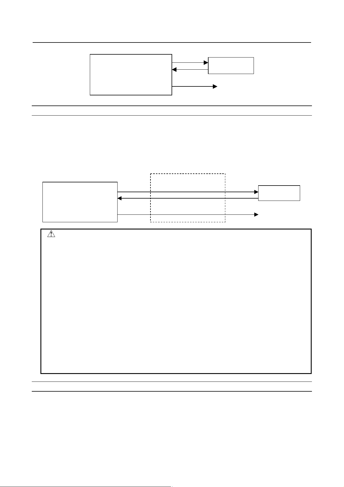
FTP mode
The host computer connected to the Data Server is selected as the external input/output device.
For example, when DNC operation or M198-based subprogram calling is executed, the relevant NC
program is called from the host computer.
When input operation is executed for the Data Server, the relevant NC program is read from the host
computer connected to the Data Server.
Conversely, when NC program output operation is executed for the Data Server, the output NC program
is directly written on the host computer.
Host computer
Data Server
Input
Output
CNC memory
DNC operation
CAUTION
1 In the FTP mode, an NC program is transferred from the host computer to the
CNC. For this reason, if the line is disconnected during communication for some
reason such as noise on the network, the disconnection directly affects the CNC
operation as compared with the storage mode. Before DNC operation in the FTP
mode, surely take measures to prevent noise and make sure that good
communication conditions are present.
2 When feed hold is performed during DNC operation in the FTP mode,
communication with the host computer may be stopped. In this case, the host
computer may disconnect the communication. Perform feed hold during a trial
run and completely confirm that the communication with the host computer is not
disconnected.
This symptom is generally caused because the CNC data read speed is slow
and the host computer causes a timeout. Depending on the machining program,
the host computer may cause a timeout even when communication is not
stopped by feed hold. If this symptom occurs, use DNC operation in the FTP
mode while being careful not to cause a timeout, or use DNC operation in the
storage mode, and not in the FTP mode.
Buffer mode
The host computer connected to the Data Server is selected as the external input device.
In the buffer mode unlike the FTP mode, however, areas on the memory card built into the Data Server
are used as intermediate buffers. For details of the buffer mode, see Section 2.3, "DETAILS OF THE
BUFFER MODE," which is the following section.
As the external output device, the memory card built into the Data Server is selected. When NC program
output operation is performed, the operation equivalent to that in the storage mode is performed.
- 18 -
Page 31

B-64014EN/07 SPECIFICATION 2.DATA SERVER FUNCTIONS
A
A
Host computer
Data Server
Memory card
Intermediate
buffers
Output
Input
CNC memory
DNC operation
NOTE
1 With the Series 30i/31i-A, to use the buffer mode, the buffer mode function
option (J728) is required.
2 With the Series 32i-A, the buffer mode cannot be used.
2.3 DETAILS OF THE BUFFER MODE
In the buffer mode, two areas (areas A and B) are prepared on the memory card. While the NC program
data stored in one area is being supplied to the CNC, the subsequent NC program data is read in the other
area from the host computer using FTP transfer. When all data in the former area has been supplied to the
CNC, the data in the latter area is supplied to the CNC. In the former area, which becomes empty, the
subsequent NC program data is read from the host computer using FTP transfer.
Repeating this operation enables an NC program larger than the capacity of the memory card to be
handled. To use the buffer mode, however, the original NC program must be divided into some files on
the host computer in advance.
The size of a divided file must be smaller than half the remaining capacity of the memory card. If the size
of a divided file is too large (for example, 100 MB or more), it takes much time to read the first file from
the host computer and it also takes time until operation starts.
Using the buffer mode
In the buffer mode, a file (such as Oxxxx) called by DNC operation or M198-based subprogram calling is
a file list. The file list contains the names of files to be called in the order in which they are to be called.
In the buffer mode, the Data Server sequentially calls the files specified in the file list from the host
computer and supplies data to the CNC.
CNC Data Server Host computer
Program
call
Oxxxx
file1
file2
file3
file4
file5
Memory card
get (FTP)
rea A
rea B
Hard disk
Oxxxx
file1
file2
file3
file4
file5
Contents
of Oxxxx
file1
file2
file3
file4
file5
- 19 -
Page 32

2.DATA SERVER FUNCTIONS SPECIFICATION B-64014EN/07
Files (file1 to file5) specified in the file list on the host computer are stored on the memory card built into
the Data Server using FTP transfer and supplied to the CNC. In the buffer mode, after the CNC issues a
request to read an NC program to the Data Server, the specified file list is read from the host computer.
When the first file has been read, the Data Server starts supplying data to the CNC. For this reason, it
takes time from when the CNC issues a request to read a program to when the Data Server starts
supplying data.
While the Data Server is supplying the data in one area to the CNC, it stores data into the other area using
FTP transfer. For this reason, divide the original program data so that two consecutive files can be
contained on the memory card built into the Data Server.
Although the data in one area has been supplied to the CNC, FTP transfer may not terminate for the other
area. In this case, program calling terminates abnormally because the subsequent data cannot be supplied.
You can use a parameter not to cause the abnormal termination.
In the file list, you can specify any file name allowed by the host computer that consists of up to 255
single-byte alphanumeric characters. Be sure to specify at least one LF (0A in hexadecimal) or CR (0D in
hexadecimal) following each file name in the file list to delimit the file names.
NOTE
In the buffer mode, you can also register a new file on the memory card built into
the Data Server by the "NC program GET" or "NC program output" operation.
By this operation, however, the remaining capacity of the memory card built into
the Data Server that is required for operation in the buffer mode may be
exhausted, resulting in an error in DNC operation in the buffer mode.
For this reason, during DNC operation in the buffer mode, do not register any
new file on the memory card built into the Data Server.
Dividing an NC program into files
To perform operation in the buffer mode, divide an original NC program into several files on the host
computer and create a file list indicating the order in which the divided files are to be transferred in
advance.
- 20 -
Page 33

B-64014EN/07 SPECIFICATION 2.DATA SERVER FUNCTIONS
Example)
Dividing an NC program into three files
%
O1234(SAMPLE);
:
:
:
X1.Y1.Z1.;
X2.Y2.Z2.;
:
:
:
X3.Y3.Z3.;
X4.Y4.Z4.;
:
:
:
M30;
%
Dividing the
program into
three files
%
O1234(SAMPLE);
:
:
:
X1.Y1.Z1.;
X2.Y2.Z2.;
:
:
:
X3.Y3.Z3.;
X4.Y4.Z4.;
:
:
:
M30;
%
file1
file2
file3
file1
file2
file3
O1234
As shown above, divide an original NC file into three files, file1, file2, and file3. Specify the divided file
names in the file list (file name: O1234).
CAUTION
In the above example, the NC program is divided into files so that any block is
not divided. You can divide a program at a point in a block. When dividing a
program at a point in a block, be careful so that any unnecessary character is
not inserted at the end of each file.
If an unnecessary character is inserted at the end of a file, the NC program may
perform unexpected operation when executed. Be very careful when preparing
and editing an NC program on the host computer.
NOTE
1 Divide an NC program into files so that each file size is about 20 to 30 MB. If the
file size is too large, it takes time until DNC operation starts. If the file size is too
small, data transmission may stop between files and operation may stop.
2 Although you can divide an NC program at a point in a block, divide the program
in block units whenever possible and retract the tool at the end of each divided
file. This prevents data transmission from stopping at the end of a file and cutter
marking from being made.
3 Store the file list and relevant divided files in the same folder (directory) on the
same host computer.
- 21 -
Page 34

2.DATA SERVER FUNCTIONS SPECIFICATION B-64014EN/07
2.4 OPERATION FROM A DATA SERVER
NOTE
The Data Server functions produce an effect when large NC programs are
operated. Use the Data Server Functions to handle large NC programs.
Memory operation
You can perform memory operation for an NC program on the memory card built into a Data Server in
the same way as for an NC program in the CNC memory.
You can also supply an NC program simultaneously for a multipath CNC system.
NOTE
When memory operation is performed, a selected NC program on the Data
Server must be a text file. It is impossible to use a binary file for memory
operation.
M198 subprogram operation
In the storage mode, you can perform M198 calling from the memory card built into a Data Server. In the
FTP or buffer mode, you can perform M198 calling form the host computer.
On the DATA SERVER FILE LIST screen, set an M198 folder in advance. When M198 calling is
specified, the set M198 folder is searched for the target subprogram.
DNC operation
In the storage mode, you can perform DNC operation from the memory card built into a Data Server. In
the FTP or buffer mode, you can perform DNC operation from the host computer.
On the DATA SERVER FILE LIST screen, set the file name for DNC operation in advance. When DNC
operation starts, the set DNC operation file is called.
- 22 -
Page 35

B-64014EN/07 SPECIFICATION 2.DATA SERVER FUNCTIONS
/
2.4.1 Subprogram Search during Memory Operation
The subprogram search sequence during memory operation for an NC program on the memory card built
into a Data Server is the same during memory operation for an NC program in the CNC program
memory.
Order in which a subprogram is c alled f rom the main program on a Data Serv er (1) to (5)
Me mory card built int o
a Dat a Server
//DATA_SV
(1) Folder containi ng
the main progra m
DIR01
DIR02
Main
program
/CNC_MEM
SYSTEM
MTB1
MTB2
USER
PATH1
LIBRARY
CNC program
memory
(5) System folder
(4) MT B-dedica ted folder 1
(3) MT B-dedica ted folder 2
(2) Common program folder
NOTE
1 You can set whether to enable search (2) to (5) in the figure above with
parameter No. 3457. For details, see “Parameter Manual” of the relevant CNC.
2 On the memory card built into a Data Server, only the subprograms in the folder
containing the main program can be executed.
3 It takes time to call a program on the memory card built into a Data Server as a
subprogram as compared with the CNC memory. Be careful when calling many
small programs.
2.5 NC PROGRAM FORMAT
NC programs prepared on the host computer must have the following format:
% TITLE ;
O0001(COMMENT) ;
⋅
⋅
⋅
M30 ;
%
An NC program starts with a start file mark (%). In the subsequent part (leader section) until EOB (;,
program start) is encountered, a comment such as a title can be inserted as necessary.
- 23 -
Page 36

2.DATA SERVER FUNCTIONS SPECIFICATION B-64014EN/07
At the beginning of the program section, be sure to specify an O number or arbitrary file name consisting
of up to 32 characters that is enclosed with “<” and “>” as the program name. This O number or file name
must be used for management on the personal computer.
If the O number or arbitrary file name in an NC program and the file name in the personal computer are
not the same, the file name in the personal computer is used basically when the program is transferred
from the personal computer to the Data Server (NOTE 2).
The semicolon ";" used at the end of each block means EOB (end of block) and actually functions as LF
(LF: 0A in hexadecimal), CR-LF (CR: 0D in hexadecimal), or LF-CR-CR.
The NC program must end with "M code ; %".
When performing binary input operation, insert data for binary input operation, enclosed with the start
code and end code of binary input operation, into the part ". . ." in the above figure.
For details of the NC program configuration and binary input operation, refer to the relevant CNC
OPERATOR’S MANUAL.
WARNING
If an NC program prepared on the host computer does not use the program
format specified by the CNC, executing the NC program can cause an
unpredictable operation. So, special care should be taken when an NC program
is prepared on the host computer.
NOTE
1 Any unrecognizable character codes in an NC program registered as a text file
on a memory card on a Data Server are ignored. Do not use any unrecognizable
character code.
A 2-byte code used for Japanese and others may be recognized as an invalid
character code when the system recognizes it on a byte-by-byte basis. Do not
use any 2-byte code used for Japanese and others.
2 The system always manages each text file on the memory card so that the file
name and the O number or arbitrary file name in the program are the same. For
this reason, if they are different, the system sets the O number or arbitrary file
name to the file name when transferring the file. The O number or arbitrary file
name in the program can also be set as the file name when the file is transferred
according to the parameter setting, however.
- 24 -
Page 37

B-64014EN/07 SPECIFICATION 2.DATA SERVER FUNCTIONS
2.6 LIST FILE FORMAT
In the LIST-GET, LIST-PUT, and LIST-DELETE functions described later, one of the following list file
formats must be used:
Format 1 Format 3
% ;
O0001(COMMENT) ;
N111 ;
N222 ;
N333 ;
:
:
N999 ;
%
Format 2 Format 4
% ;
O0001(COMMENT) ;
N111 (PC-File) ;
N222 (PC-File) ;
N333 (PC-File) ;
:
:
N999 (PC-File) ;
%
Specifications common to all formats
<1> A list file begins with a start file mark "%".
<2> In the next block, be sure to specify an O number. Assign this O number as the file name.
A comment enclosed in parentheses "(" and ")" can be inserted between the O number and EOB.
<3> In the subsequent blocks, specify files to be processed.
<4> The list file must end with "%".
Specifications of format 1
The following describes the specifications of list file format 1:
<1> This specification method applies when the file names of files to be processed have the format
"Oxxxx" (where "xxxx" denotes a 4-digit number). In this case, change "O" in file name "Oxxxx" to
"N" when specifying the file name. The 4-digit number can be zero-suppressed. The example shows
that files O0111, O0222, O0333, and so on up to O0999 are processed sequentially.
<2> The LIST-GET service transfers "Oxxxx" files stored on the built-in hard disk of the host computer
to the built-in memory card of the Fast Data Server without modifying file names "Oxxxx". The
LIST-PUT service transfers "Oxxxx" files stored on the built-in memory card of the Fast Data
Server to the built-in hard disk of the host computer without modifying file names "Oxxxx". The
LIST-DELETE service deletes "Oxxxx" files stored on the built-in memory card of the Fast Data
Server.
% ;
O0001(COMMENT) ;
(Dtsvr-File) ;
(Dtsvr-File) ;
(Dtsvr-File) ;
:
:
(Dtsvr-File) ;
%
% ;
O0001(COMMENT) ;
(Dtsvr-File, PC-File) ;
(Dtsvr-File, PC-File) ;
(Dtsvr-File, PC-File) ;
:
:
(Dtsvr-File, PC-File) ;
%
- 25 -
Page 38

2.DATA SERVER FUNCTIONS SPECIFICATION B-64014EN/07
Specifications of format 2
The following describes the specifications of list file format 2:
<1> This specification method applies when files to be processed are named "Oxxxx" (where "xxxx"
denotes a 4-digit number) on the built-in memory card of the Fast Data Server and are named
arbitrary file names on the built-in hard disk of the host computer. In this case, change "O" in file
name "Oxxxx" to "N" when specifying the file name on the Fast Data Server. The 4-digit number
can be zero-suppressed. The example shows that files O0111, O0222, O0333, and so on up to O0999
are processed sequentially.
A file name on the built-in hard disk of the host computer can be specified by enclosing it with
parentheses "(" and ")" following the corresponding "Nxxxx". The characters that can be used in file
names depend on the OS of the host computer.
<2> The LIST-GET service transfers files with arbitrary file names "PC-File" stored on the built-in hard
disk of the host computer to the built-in memory card of the Fast Data Server as "Oxxxx" files. The
LIST-PUT service transfers "Oxxxx" files stored on the built-in memory card of the Fast Data
Server to the built-in hard disk of the host computer as files with arbitrary file names "PC-File". The
LIST-DELETE service deletes "Oxxxx" files stored on the built-in memory card of the Fast Data
Server.
Specifications of format 3
The following describes the specifications of list file format 3:
<1> This specification method applies when the file names of files to be processed are arbitrary file
names. In this case, file names on the built-in memory card of the Fast Data Server and on the
built-in hard disk of the host computer are assumed to be the same. Specify an arbitrary file name
enclosed with parentheses "(" and ")". The characters that can be used in arbitrary file names are the
following 66 ASCII characters only:
Numeric characters 0 to 9
Lowercase letters a to z
Uppercase letters A to Z
Four symbols (+, -, _, .)
<2> The LIST-GET service transfers files with arbitrary file names "Dtsvr-File" stored on the built-in
hard disk of the host computer to the built-in memory card of the Fast Data Server with the file
names kept unchanged.
The LIST-PUT service transfers "Dtsvr-File" files stored on the built-in memory card of the Fast
Data Server to the built-in hard disk of the host computer with the file names "Dtsvr-File" kept
unchanged. The LIST-DELETE service deletes "Dtsvr-File" files stored on the built-in memory card
of the Fast Data Server.
Specifications of format 4
The following describes the specifications of list file format 4:
<1> This specification method applies when files to be processed have arbitrary file names. In this case,
file names on the built-in memory card of the Fast Data Server and file names on the built-in hard
disk of the host computer are assumed to be different. Specify a file name on the built-in memory
card of the Fast Data Server and a file name on the built-in hard disk of the host computer in
parentheses, separated by a comma ",".
The characters that can be used in file names on the built-in memory card of the Fast Data Server are
the following 66 ASCII characters only:
Numeric characters 0 to 9
Lowercase letters a to z
Uppercase letters A to Z
Four symbols (+, -, _, .)
The characters that can be used in arbitrary file names on the built-in hard disk of the host computer
depend on the OS of the host computer.
<2> The LIST-GET service transfers files with arbitrary file names "PC-File" stored on the built-in hard
disk of the host computer to the built-in memory card of the Fast Data Server as "Dtsvr-File" files.
- 26 -
Page 39

B-64014EN/07 SPECIFICATION 2.DATA SERVER FUNCTIONS
The LIST-PUT service transfers "Dtsvr-File" files stored on the built-in memory card of the Fast
Data Server to files with file name "PC-File" on the built-in hard disk of the host computer.
The LIST-DELETE service deletes "Dtsvr-File" files stored on the built-in memory card of the Fast
Data Server.
Limitations on file names in a list file
The following limitations apply when file names are specified in a list file:
<1> The characters that can be used in file names on the built-in memory card of the Fast Data Server are
the following 66 ASCII characters only:
Numeric characters 0 to 9
Lowercase letters a to z
Uppercase letters A to Z
Four symbols (+, -, _, .)
The characters that can be used in arbitrary file names on the built-in hard disk of the host computer
depend on the OS of the host computer.
<2> Up to 255 characters can be used as an arbitrary file name on the built-in hard disk of the host
computer. However, the number of characters that can actually be used depends on the OS of the
host computer.
Storage locations of list files
The LIST-GET, LIST-PUT, and LIST-DELETE services are useful functions for managing NC programs
in groups.
The places where list files are prepared vary depending on the service to be executed.
For the LIST-GET service, NC programs to be operated on are present on the built-in hard disk of the
host computer, so list files are placed also on the built-in hard disk of the host computer.
For the LIST-PUT and LIST-DELETE services, NC programs to be operated on are present on the
built-in memory card of the Fast Data Server, so list files are also prepared on the built-in memory card of
the Fast Data Server.
2.7 DATASERVER Explorer CONNECTION
The following functions are added to FTP Server function of Data Server.
• Increase of FTP Server connections.
The number of FTP server connections can be increased from five to ten by this feature.
• Connection with Windows Explorer.
When you use the Windows Explorer as an FTP client software, you can make a new folder and
overwrite a file.
For the FTP client operation using the Explorer, see APPENDIX D.2, "OPERATION USING THE
Explorer."
• Addition of maintenance screen for FTP server.
You can monitor the state of FTP server. And you can disconnect the connection of FTP client
forcedly.
For the operation of the maintenance screen, see Section 2.5, "FTP SERVER MAINTENANCE" in
Part VI, "MAINTENANCE."
NOTE
1 To use the DataServer Explorer connection, the DataServer Explorer connection
option (R953) is required.
2 Some FTP client software programs may each internally use two or more FTP
clients. Note, therefore, that the number of FTP clients is not always equal to the
number of applications.
- 27 -
Page 40

2.DATA SERVER FUNCTIONS SPECIFICATION B-64014EN/07
2.8 ISO CODE INPUT/OUTPUT FUNCTION
Use this function to input and output NC data between the CNC and Data Server and between the
personal computer and Data Server using the ISO code. Parity information is added to the ISO code
unlike the conventional ASCII code. This function checks this parity information, which improves the
reliability of data input/output.
While the most significant bit of the ASCII code is OFF, the most significant bit of the ISO code is used
as parity information so that the number of ON bits per character is even.
NOTE
1 NC data may not be able to be transferred correctly between the personal
computer and Data Server, depending on the FTP communication software on
the personal computer used.
2 If an ISO code parity error is detected in a comment part, no error is caused and
the relevant character is converted to a blank character.
3 When the ASCII code is selected as the input/output code, parity information is
not checked. The parity information in the most significant bit is removed and the
data is transferred as the ASCII code even if ISO code data is transferred.
4 To input and output data between the CNC and Data Server, a Data Server must
be selected as an I/O device. For details of the selection of an I/O device and
input/output code, see Section 2.2, "RELATED NC PARAMETERS" in Part III,
"SETTING".
5 Prepare NC data using the ISO code on the personal computer regardless of
which Data Server mode is selected.
For details of Data Server modes, see Section 2.2, "DATA SERVER MODES".
A tool (FANUC ISO Converter) is available for creating and checking NC data
using the ISO code on the personal computer. For details of this tool, refer to
Appendix in "OPERATOR'S MANUAL (Common to Lathe System/Machining
Center System)" of the relevant CNC.
6 With the Series 30i/31i/32i-A, the ISO code input/output function cannot be used.
Input from a Data Server to the CNC
When the ISO code is selected as the input/output code and the CNC receives data from a Data Server,
the ISO code input/output function checks the ISO code for data validity.
If the function detects any character with wrong parity information, it terminates abnormally.
Target functions
(1) Program input
(2) M198-based subprogram call
(3) DNC operation
NOTE
1 On the CNC, the function checks the ISO code of received data regardless of
whether the file from the Data Server is a text or binary file.
For details of text and binary files, see Subsection 2.1.3, "Text Files and Binary
Files".
2 On the CNC, the function checks the ISO code of received data regardless of
which Data Server mode is selected.
For details of Data Server modes, see Section 2.2, "DATA SERVER MODES".
- 28 -
Page 41

B-64014EN/07 SPECIFICATION 2.DATA SERVER FUNCTIONS
Output from the CNC to a Data Server
When the ISO code is selected as the input/output code, the ISO code input/output function checks the
ISO code for data validity before data is stored on the memory card on the Data Server.
If the function detects any character with wrong parity information, it terminates abnormally.
Target functions
(1) Program output
NOTE
1 When the Data Server is in the FTP mode, data is output directly to the personal
computer, and the ISO code input/output function does not check the ISO code
on the Data Server. In this case, check the data on the personal computer
separately.
2 When multiple NC programs are output at a time or NC parameters are output,
they are output as binary files to the Data Server.
The ISO code input/output function does not check the ISO code in binary files
on the Data Server.
File transfer from the personal computer to the Data Server
When the ISO code is selected as the input/output code, the ISO code input/output function checks the
ISO code for data validity before data received from the personal computer is stored on the memory card
on the Data Server.
If the function detects any character with wrong parity information, it terminates abnormally.
Target functions
(1) GET (The Data Server operates as an FTP client.)
(2) PUT (The Data Server operates as an FTP server.)
NOTE
1 Prepare NC data using the ISO code on the personal computer.
2 When a binary file is transferred, the ISO code input/output function does not
check the ISO code before the file is stored on the memory card on the Data
Server.
3 During FTP transfer between the personal computer and Data Server, data
validity is checked as the FTP transfer protocol function.
The ISO code check can be enabled to check data redundantly.
File transfer from the Data Server to the personal computer
When the ISO code is selected as the input/output code, data is output using the ISO code from the
memory card on the Data Server.
Target functions
(1) PUT (The Data Server operates as an FTP client.)
(2) GET (The Data Server operates as an FTP server.)
- 29 -
Page 42

2.DATA SERVER FUNCTIONS SPECIFICATION B-64014EN/07
NOTE
1 Check the ISO code on the personal computer as required.
2 When a binary file is transferred, it is not converted to the ISO code on the Data
Server.
3 During FTP transfer between the personal computer and Data Server, data
validity is checked as the FTP transfer protocol function.
The ISO code check can be enabled to check data redundantly.
- 30 -
Page 43

B-64014EN/07 SPECIFICATION 3.FOCAS2/Ethernet FUNCTIONS
3 FOCAS2/Ethernet FUNCTIONS
The FOCAS2/Ethernet functions can remotely control and monitor the CNC by using a personal
computer. For details, refer to the manual delivered with the FOCAS2 library software.
NOTE
1 In the FOCAS2/Ethernet functions, the CNC operates as a server and waits for a
communication start request from a personal computer that operates as a client.
As communication with the personal computer starts, two sockets are used for
control and monitoring from the personal computer and for file transfer.
2 For the FOCAS2/Ethernet functions, the machine tool builder or end user can
create desired software operated on each personal computer using the FOCAS2
library software.
Communication timing and other factors may vary depending on the personal
computer environment. Before starting communication, completely confirm that
there is no problem with the entire system including communication with the
personal computer.
3 The Program Transfer Tool is available as a PC tool for transferring NC
programs between the CNC and personal computer. (drawing number:
A08B-9510-J515) This tool allows NC programs to be transferred between a
personal computer and CNC memory or Data Server memory card through a
simple operation on the personal computer side. The transfer of NC programs
between a personal computer and CNC memory requires the FOCAS2/Ethernet
functions, and that between a PC and Data Server memory card requires the
Data Server functions.
- 31 -
Page 44

4.DNS/DHCP CLIENT FUNCTIONS SPECIFICATION B-64014EN/07
4 DNS/DHCP CLIENT FUNCTIONS
If DNS/DHCP is used for communication setting of the Data Server functions and FOCAS2/Ethernet
functions, Ethernet addresses (IP address and subnet mask) can be set at a time on the host computer to
facilitate Ethernet address control.
DNS
With the DNS function, a fully qualified domain name (e.g., www.fanuc.co.jp) can be specified instead of
a hard-to-remember IP address just consisting of numbers (e.g., 192.168.0.10) when a TCP/IP
communication destination is to be specified.
NOTE
To use the DNS function, a personal computer having the DNS server function is
additionally required. See Chapter 4, "SETTING THE DNS/DHCP FUNCTION,"
in Part III, "SETTING," and APPENDIX C, "EXAMPLE OF SETTING UP
DNS/DHCP."
DHCP
With the DHCP function, Ethernet addresses (IP address and subnet mask) that need to be set on the CNC
can be set on the host computer.
NOTE
To use the DHCP function, a personal computer having the DHCP server
function is additionally required. See Chapter 4, "SETTING THE DNS/DHCP
FUNCTION," in Part III, "SETTING," and Appendix C, "EXAMPLE OF SETTING
UP DNS/DHCP."
- 32 -
 Loading...