


ADDITIONAL INFORMATION

FANUC Series 30i –MODEL B
FANUC Series 31i –MODEL B
FANUC Series 32i –MODEL B
Common to Lathe System / Machining Center System
1. Type of applied technical documents
Name
FANUC Series 30i –MODEL B
FANUC Series 31i –MODEL B
FANUC Series 32i –MODEL B
Common to Lathe System / Machining Center System
OPERATOR'S MANUAL
OPERATOR'S MANUAL
Spec.No./Version
B-64484EN/01
2. Summary of change
Group Name / Outline New,
Basic
Function
The description of the maximum number of files of the USB
memory folder screen was corrected. Parameter No.11376 was
added.
The description of “Multiple programs on memory card selection
input function” is added.
The description of “Overwriting confirmation when program is input
Add,
Correct,
Delete
Correct,
Add
Add
Add
Applicable
Date
Immediately
ED
Date
Date
and file is output” is added.
The description about deleting a folder recursively is added.
The description of improvement of folder management is added.
The description of power consumption monitoring screen is added.
Title
Common to Lathe System / Machining Center System
Draw
No.
Design
2010.06.18
Design
Description Page
Approve
Add
Add
Add
FANUC Series 30i / 31i / 32i-MODEL B
OPERATOR'S MANUAL
B-64484EN/01-01
1/2

Optional
Function
The description of Rate Feed function is added.
The description of Plane Conversion function is added.
The description of Stored Pitch Error Compensation function is
added and corrected.
The description of High-speed Smooth TCP is added and corrected
The description of Rigid Tapping By Manual Handle is added.
The description of Three-dimensional Rotary Error Compensation is
added and corrected
The description of 5-axis machining configuration selecting function
Add
Add
Add
Correct
Add
Correct
Add
Correct
Add
New
Immediately
is added and corrected.
Unit
Maintenance
parts
Notice - This function is available in the following software.
G301,G311,G321, G331,
G401,G411,G421,G431,G501 : 01.0 or later
Correction
Another
ED
Date
Date
Design
2010.06.18
Design
Title
Draw
No.
Description Page
Approve
FANUC Series 30i / 31i / 32i-MODEL B
Common to Lathe System / Machining Center System
OPERATOR'S MANUAL
B-64484EN/01-01
2/2

Replace the NOTE in "8 DATA INPUT/OUTPUT" of "III. OPERATION" with following description.
NOTE
1 If the external input/output device is other than a data server interface or
embedded Ethernet interface, a file name of up to 12 characters can be handled.
NC programs on the memory of the CNC can each be assigned any file name of
up to 32 characters, but the name is restricted to up to 12 characters in the
input/output to and from external I/O devices.
2 If the external input/output device is a data server interface, embedded Ethernet
interface, or USB memory interface, a file name of up to 32 characters can be
handled.
3 When a memory card interface is used as an external I/O device, up to 512 files
can be handled.
ED
Date
Date
Design
2010.06.17
Design
Title
Draw
No.
Description Page
Approve
FANUC Series 30i / 31i / 32i-MODEL B
USB memory folder screen
B-64484EN/01-01
1/4

Replace "Limitation" in "11.1.3 Selecting a USB Memory as a Device" with following description.
Limitation
There are the following restrictions on the USB function.
(1) Only one USB memory can be recognized. (No USB hub can be recognized.)
(2) Up to 32 characters can be used for a file or folder name.
If a file or folder name is longer than 32 characters, the 32nd character is replaced with a tilde (~) and the
subsequent characters are omitted when displayed. All operations including management operation and
input/output cannot be performed for a file or folder whose name is omitted with a tilde (~).
(3) The maximum number of folder levels is 6 (excluding the root folder).
(4) In case of setting that is sorted by the file name (parameter SOR(No.3107#4)=1), the maximum number of
files and folders that can be the display in a folder is 512. Do not store more than 512 files in the USB
memory.
(5) If a non-ASCII character (alphanumeric character) is used in a file or folder name, it cannot be displayed
correctly.
For detailed specifications of and restrictions on a USB memory, see the section related to the USB function.
NOTE
1 Remove a USB memory only when “REMOVE OK” is displayed as the USB
memory status, or data may be damaged.
2 When the free space of the USB memory is a little or when a large amount of file
is in the USB memory, it might take time to operate the USB memory. In the
default configuration, warning "TIME-OUT" is displayed after 30 seconds
passed, and the operation of the USB memory stops. When the period of the
time-out is changed, set parameter No.11376 .
- Operation of creation, edition, and management of a program
When “USB memory as a device” is selected, operation of creation, edition, and management of a program is
below (Table 11.1.3 (a)):
Table 11.1.3 (a)
Item Usable
Creation of a program Unusable
Edition prohibition attribute Unusable
Inserting, alteration, and deletion a Word Unusable
Deletion of a block Unusable
Program search Usable
Sequence number search Unusable
Deletion of a program Usable
Editing a custom macro Unusable
Password function Unusable
Editing a program character Unusable
Program copy function Unusable
Key and program encryption Unusable
Selecting a device Usable
Creation of a folder Usable
Renaming of a folder Usable
Changing the attribute of a folder Unusable
ED
Date
Date
Design
2010.06.17
Design
Title
Draw
No.
Description Page
Approve
FANUC Series 30i / 31i / 32i-MODEL B
USB memory folder screen
B-64484EN/01-01
2/4

Item Usable
Deletion of a folder Usable
Selecting a default folder Unusable
Renaming of a file Usable
Deletion of a file Usable
Changing the attribute of a file Unusable
Selecting a main program Unusable
Making a program compact Unusable
Input/output of program Usable
ED
Date
Date
Design
2010.06.17
Design
Title
Draw
No.
Description Page
Approve
FANUC Series 30i / 31i / 32i-MODEL B
USB memory folder screen
B-64484EN/01-01
3/4

Add the parameter No. 11376 to "A.1 DESCRIPTION OF PARAMETERS" of APPENDIX .
11376 Time-out period of USB memory
[Input type] Parameter input
[Data type] Word
[Unit of data] sec
[Valid data range] 0 to 32767
Set the time-out period of the USB memory. Please adjust this parameter according to the USB
memory.
NOTE
When 0 is set in this parameter, it is assumed to 30.
ED
Date
Date
Design
2010.06.17
Design
Title
Draw
No.
Description Page
Approve
FANUC Series 30i / 31i / 32i-MODEL B
USB memory folder screen
B-64484EN/01-01
4/4

App
p
Add the following specification in
Ⅲ Operation,
10.12.2 “Copy of program file with memory card device”
10.12.3 “Deleting files in memory card device”
10.12.2 Copy of program file with memory card device
Overview
In the program list screen, the program file can be input and output between the memory cards connected as
an external input-output device and program memory (CNC MEM) on CNC by the same operation as the copy
of the program file.
NOTE
1 This function targets the memory card by the PCMCIA interface connected as an
external input-output device.
2 Change the following parameter setting to copy the program file between the memory
cards and program memory.
Patameter No.20-23 are set to 4.
・
Bit 0 (IO4) of parameter No.0110 is set to 0.
・
When Bit 0 (IO4) of parameter No.0110 is set to 1, and sets parameter No.20-23 to a
value that means input-output device other than the memory card,
warning " CHANGE EXTERNAL DEVICE TO MEMORYCARD" is occurred,
and the file with the memory card cannot be copied.
Explanation
・Cnc mode when the copy is operated
Change to the EDIT mode when the file is copied between different devices.
In the multi path system, change the entire path to the EDIT mode.
Warning "CHANGE TO EDIT MODE" is occurred excluding the EDIT mode in any mode except EDIT.
・Selection of file
The file is selected according to the program file selection operation that becomes effective because of the bit 3
(PCP) of parameter No.11374 is set to 1.
The file that can be selected as a copy target is only a file in the same folder.
・Copy of program file
When the program file is copied from the program memory to the memory card, the selected program is output
to the memory card.
When the program file is copied from the memory card to the program memory, the selected file is read to the
program memory.
FANUC Series 30i / 31i / 32i-MODEL B
Title
Draw
No.
Date
ED
Date
Design
2010.06.17
Description
rv.Design
Multiple programs on memory card
selection in
ut function
B-64484EN/01-01
Page
1/3

App
p
・File that can be copied
The file that can be output to the memory card by the copy operation is only a program file on the CNC-MEM
device. Therefore, the file that exists in other devices except the CNC-MEM and folder cannot be output.
NOTE
Even if the folder has been selected during output operation to the memory card, the
folder is not output.
・Overwrite of program file
The file is overwritten according to the program file overwriting operation by setting the bit 3 (PCP) of
parameter No.11374 to 1.
NOTE
Operation when the file is copied to the memory card depends on the setting of bit 1
(COW) of parameter No.11308.
Operation when the file is copied to the program memory of CNC depends on the
setting of bit 2 (REP) of parameter No.3201.
Restrictions
・File operation restrictions on devices
A copy or movement between the following devices is possible.
・ CNC MEM
・ MEM CARD (binary format)
(However, this device can only be selected as the copy source folder from which a file is read.)
・ Data server
・ Memory card
(However, This device can do only the copy operation with the CNC MEM device.
Moreover, this device cannot be used together with MEM CARD.)
For devices other than the above, a copy or movement between them is impossible.
If an attempt is made to perform a copy or movement, the warning message "CAN NOT COPY/MOVE"
appears.
・Copy of file including some programs
Don’t input anything to the key input buffer when you copy the file including some programs.
When some programs are included in the file of the copy origin, if the character string is input to the key input
buffer, only the program of the head in the file is read to CNC MEM with program name input to the key input
buffer.
・File name on memory card
When the program with 8 character or more name of the program in the program memory on CNC is output, it
is output on the memory card as follows.
For eight digits O numbers ('O'+ numeric parts)
・The numeric parts are 8 digits or more:
The file name is changed to eight numerical value digits except first 'O'.
Example) O12345678 → 12345678
・The numeric parts are less than 8 digits:
One digit is deleted '0' and program name is changed to seven digits of 'O' + numerical value.
FANUC Series 30i / 31i / 32i-MODEL B
Title
Draw
No.
Date
ED
Date
Design
2010.06.17
Description
rv.Design
Multiple programs on memory card
selection in
ut function
B-64484EN/01-01
Page
2/3

App
p
Example) O00012345 → O0012345
For arbitrary program name (9 characters or more)
・Program name is changed to the file name that rounds down since the ninth character.
Example) 123456789 → 12345678
The file name output on the memory card might overlap by the above operation. In this case, it is output
according to the setting of bit 1 (COW) of parameter No.11308.
10.12.3 Deleting files in memory card device
Overview
The file on the memory card can be deleted according to the operation of program file deletion by setting the bit
3 (PCP) of parameter No.11374 to 1.
FANUC Series 30i / 31i / 32i-MODEL B
Title
Draw
No.
Date
ED
Date
Design
2010.06.17
Description
rv.Design
Multiple programs on memory card
selection in
ut function
B-64484EN/01-01
Page
3/3

g
App
Add the following specification in
Ⅲ Operation,
10.12.4 “Overwriting confirmation when programs are input”
10.12.5 “Overwriting confirmation when file is output”
10.12.4 Overwriting confirmation when programs are input
Overview
When the program is input and there is already another program whose name is the same as the former, it is
possible to select whether the program is overwritten or not, by the softkey operation.
Inputing a program
Procedure
Operate the following procedures on the ALL IO screen, the program edit screen, and the program list screen.
1 Press the soft key [F INPUT].
2 Specify the input file name, and press the soft key [F SET].
When the file name is not specified, the file of the default file name is input.
3 Specify the input program name, and press the soft key [P SET].
When the program name is not specified, programs in the file are input.
4 Press the soft key [EXEC]. The following softkey is displayed.
Fig.10.12.4 (a) Softkey display during input operation(10.4inch)
5 When the program of the same name is already existed in the destination, the confirmation message
“Overwrite ? ‘input program name’ ” and the following softkey are displayed.
Fig. 10.12.4 (b) Confirmation of overwriting by input operation in program list screen(10.4inch)
・ When the softkey [YES] is pressed, only the same program as the name displayed in the confirmation
message is input by the overwriting.
・ When the softkey [NO] is pressed, the program of the same name displayed in the confirmation message is
skipped, and input from the next file.
When the program of the same name is found again, the above confirmation message is displayed in every
case.
FANUC Series 30i / 31i / 32i-MODEL B
Title
Overwriting confirmation when
program is input and file is output
Draw
No.
Date
ED
Date
Date
Design
2010.06.17
Desi
n
Description
rv.
B-64484EN/01-01
B-64484EN/01-01
Page
1/3

g
App
・ When the softkey [YES ALL] is pressed, all programs of the same name displayed in the confirmation
message and programs of the same name after that are input by the overwriting.
・ When the softkey [NO ALL] is pressed, all programs of the same name displayed in the confirmation
message and programs of the same name after that are not input.
・ When the softkey [CANCEL] is pressed, the input is ended. Moreover, when the return menu key is
pressed, the input is similarly ended.
The softkey returns to the display before the softkey [F INPUT] is pressed when the input of all programs ends.
The input operation is canceled when the mode is switched and the screen are switched to another screen while
confirming the overwriting.
NOTE
1 The input is interrupted when there is a protected program.
2 The overwriting confirmation is canceled as well as the switch to another screen, and
the input ends, when switching to full screen display between small screen display or
the path is switched while confirming the overwriting.
3 When the programs are input to effective the overwriting confirmation function on the
background editting (the bit 2 (REP) of parameter No.3201 and bit 3 (PCP) of
parameter No.11374 are set to 1), the program is input at last is selected as a
program for the background editing.
The program for the background editing even if the program is input by the
background editing when the folder to be input has been selected on each screen is
not changed, when the overwriting confirmation function cannot be used (the bit 7
(FLI) of parameter No.11364 is set to 1).
4 The program that input the program of the same name before failing if failing in input
for the reasons such as protecting the program input while editing the background
when the folder to be input is a setting that inputs the overwriting (the bit 2 (REP) of
parameter No.3201 is set to 1, and bit 3 (PCP) of parameter No.11374 is set to 0),
and is foreground or a background folder (bit 7 (FLI) of parameter No.11364 is set to
0) is selected to the program for the background editing. The program of the
background editing is not changed even if failing in the input of the program of the
head when the overwriting confirmation function is available.
5 The overwriting confirmation cannot be used by inputting the background editing.
10.12.5 Overwriting confirmation when file is output
Overview
On the bit 1 (COW) of parameter No.11308 is set to 1, when the file of same name had already exist when the
NC data of the program and the parameter, etc. was output to an external input-output device, it is possible to
select the overwriting or cancel the output to file by the operation.
Operation procedure in normal output
Procedure
Operate the following procedures on the screen where the NC data can be output.
FANUC Series 30i / 31i / 32i-MODEL B
Title
Draw
No.
Date
ED
Date
Date
Design
2010.06.17
Desi
n
Description
rv.
Overwriting confirmation when
program is input and file is output
B-64484EN/01-01
B-64484EN/01-01
Page
2/3

g
App
1 Press the soft key [F OUTPUT].
2 Specify the input file name, and press the soft key [F SET].
When the file name is not specified, the file of the default file name is output.
3 Press the soft key [EXEC].
4 Only when the file of the same name exists at the output destination, the confirmation message of
following softkey and "OVERWRITE ?" is displayed.
Fig.10.12.5 (a) Overwriting confirmation by output operation(10.4inch)
・ When the softkey [YES] is pressed, the file of same name is overwritten, and the file is output.
・ When the softkey [CANCEL] is pressed, the output is ended. Moreover, when the return menu key is
pressed, the output is similarly ended.
Operation procedure in all output
Procedure
Operate the following procedures on the ALL IO screen.
1 Press the soft key [ALL OUTPUT].
2 The input file name is specified, and press the soft key [F SET].
When the file name is not specified, the file of the default file name is output.
3 Press the soft key [EXEC].
4 Only when the file of the same name exists at the output destination, the confirmation message of
following softkey and "‘Output file name’ OVERWRITE ? " is displayed.
Fig.10.12.5 (b) Overwriting confirmation by all output operation(For the offset data)(10.4inch)
・ When the softkey [YES] is pressed, the file of the same name displayed in the confirmation message is
overwritten, and the file is output..
・ When the softkey [YES ALL] is pressed, the file of the same name displayed in the confirmation message
and all files of the same name after that are output by the overwriting.
・ When the softkey [CANCEL] is pressed, the output is ended. Moreover, when the return menu key is
pressed, the output is similarly ended.
FANUC Series 30i / 31i / 32i-MODEL B
Title
Draw
No.
Date
ED
Date
Date
Design
2010.06.17
Desi
n
Description
rv.
Overwriting confirmation when
program is input and file is output
B-64484EN/01-01
B-64484EN/01-01
Page
3/3

y
Add the following description to III OPERATION 11.5.1 “DELETING A FOLDER RECURSIVELY”.
11.5.1 DELETING A FOLDER RECURSIVELY
This function enables the deletion of the folder that includes programs and folders.
Explanation
When a folder is deleted, all the programs and folders in the folder is deleted.
This function is enabled by setting bit 3 (FDR) of parameter No. 11364.
In the program list screen (CNC built-in memory), this function is available.
Procedure
1. Display the program list screen.
2. Move the cursor to a folder to delete.
3. Press the softkey [DELETE].
4. Press the softkey [EXEC].
5. The folder is deleted. All the programs and folders in the folder are also deleted.
NOTE
Following programs, folders and folders that include them are not deleted.
- The executed programs
- The programs which are selected in foreground
- The current folder
By following function, protected programs, folders and the folders that include them are not
deleted, too.
- Key and program encryption
- NE8/NE9 parameter protection
- Protection of data at eight levels
- Read only attribute
When some programs and folders are not deleted, the warning “PROGRAM IN FOLDER IS
NOT DELETED” is displayed.
ED
Date
Date
Design
2010.06.17
Design
Title
Draw
No.
Description Page
Approve
FANUC Series 30i / 31i / 32i-MODEL B
Deleting a folder recursivel
B-64484EN/01-01
1/2

y
Add the following description to APPENDIX A PARAMETERS.
#7 #6 #5 #4 #3 #2 #1 #0
11364 FDR
[Input type] Parameter input
[Data type] Bit
#3 FDR When the folder that includes programs or folders are tried to be deleted,
0: the folder is not deleted.
1: the folder, and the program and the folders in it are deleted.
ED
Date
Date
Design
2010.06.17
Design
Title
Draw
No.
Description Page
Approve
FANUC Series 30i / 31i / 32i-MODEL B
Deleting a folder recursivel
B-64484EN/01-01
2/2

g
Add the following as 11.13 “Folder management” of III OPERATION.
11.13 Folder management
This function restricts the folder operation in program management. As a result, operator can manage the
program without the complex folder operation. Following two specifications can be selected by the parameter.
1) The folders under the path folders can be used for program management.
2) Only the path folders can be used for program management.
Path folders are the one of the initial folders. The folder exists under //CNC_MEM/USER, and the number is
same to the system path. Please refer to USER’S MANUAL (B-64484EN, II 12 PROGRAM
MANAGEMENT) for details.
ED
Date
Date
Design
2010.06.17
Design
Title
Draw
No.
Description Page
Approve
FANUC Series 30i / 31i / 32i-MODEL B
Folder mana
ement
B-64484EN/01-01
1/6

g
//CNC_MEM
/
SYSTEM/
MTB1/
MTB2/
USER/
1)
PATH1/
CYLINDER/
2)
PISTON/
Fig.11.13 (a) Folder that can be used by each setting
PATH2/
LIBRARY/
User created folder
GEAR1/
GEAR2/
ED
Date
Date
Design
2010.06.17
Design
Title
Draw
No.
Description Page
Approve
FANUC Series 30i / 31i / 32i-MODEL B
Folder mana
ement
B-64484EN/01-01
2/6

g
11.13.1 Program management under the path folder
If parameter FPF (No.11302#6) is set to “1”, the operation on the program folder screen becomes as follows. At
this time, it is necessary to set parameter CFP (No.11304#7) to “0”.
Table 11.13.1 (a) Restriction of operation
Operation Working
Moving of the folder
Creating of user folder Possible
Changing of foreground default folder Possible
Changing of background default folder Possible
Display on program folder screen
Only the folder under the path folder corresponding to selected path can be displayed.
Warning message “CAN’T MOVE TO FOLDER” is displayed and cannot move when the folder is operated to
move upper from the path folder.
Setting of foreground/background default folder
Only the folder under the path folder corresponding to selected path can be set to foreground/background
default folder.
Under the path folder Possible
Upper from the path folder Impossible
ED
Date
Date
Design
2010.06.17
Design
Title
Draw
No.
Description Page
Approve
FANUC Series 30i / 31i / 32i-MODEL B
Folder mana
ement
B-64484EN/01-01
3/6

g
)3)
11.13.2 Program management only in the path folder
If Parameter CFP (No.11304#7) is set to 1, the operation on the program folder screen becomes as follows. At
this time, the setting of parameter FPF (No.11302#6) is invalid.
Table 11.13.2 (a) Restriction of operation
Operation Working
Moving of the folder
Creating of user folder Impossible
Changing of foreground default folder Impossible
Changing of background default folder Impossible
Display on program folder screen
Only the path folder corresponding to selected path can be displayed. “RETURN TO UPPER FOLDER” is
not displayed. (Refer to “1)” in Fig. 11.13.2 (a) and Fig. 11.13.2 (b).)
The subfolder that has already been made under the path folder before the parameter CFP(No.11304#7) is made
effective can be displayed. But it is impossible to move to the subfolder.
Under the path folder Impossible
Upper from the path folder Impossible
2)
1
Fig.11.13.2 (a) Program folder screen(parameter CFP(No.11304#7)=0)
Title
Draw
No.
Date
ED
Date
Design
2010.06.17
Design
Description Page
Approve
FANUC Series 30i / 31i / 32i-MODEL B
Folder mana
ement
B-64484EN/01-01
4/6

g
)
)3)
3)
2)
1)
Fig.11.13.2 (b) Program folder screen(parameter CFP(No.11304#7)=1)
Display of device name and current folder
The current folder name is not displayed though the device name is displayed so far. (Refer to “2)” in Fig.
11.13.2 (a) and Fig. 11.13.2 (b).)
Display and setting of foreground/background default folder
Foreground/background default folders are not displayed. (Refer to “3)” in Fig. 11.13.2 (a) and Fig. 11.13.2
(b).)
Moreover, foreground/background default folders cannot be set.
Note
Set foreground/background default folder to each path folder before the
parameter CFP(No.11304#7) is made effective.
Softkey that is not displayed
The following soft key is not displayed, and cannot be operated.
・ CREATE FOLDER 1)
・ FORE CHANGE 2)
・ BACK CHANGE 3)
1
2
Fig11.13.2 (c) Softkey display for CNC_MEM device
Title
Draw
No.
Date
ED
Date
Design
2010.06.17
Design
Description Page
Approve
FANUC Series 30i / 31i / 32i-MODEL B
Folder mana
ement
B-64484EN/01-01
5/6

g
11.13.3 Folder for subprogram/macro calls
In the following subprogram call/macro call, the folder /USER/LIBRARY, /MTB12, /MTB2 and /SYSTEM are
searched before the folder where there is the main program are searched.
There is a possibility being executed for the subprogram that the operator doesn't intend if the subprogram is
registered to the above-mentioned folder even if the display and the operation are limited by this function.
-Subprogram call based on an M code
-Subprogram call based on a particular address
-Subprogram call based on a second auxiliary function code
-Macro call based on a S code
-Macro call based on a G code
-Macro call based on an M code
-Macro call based on a T code
-One-touch macro call
By setting 1 to the parameter SCC (No.3457#6), the folder where there is the main program is added to the top
of search order.
1) Folder where the main program is stored. ← Added.
2) Common program folder of initial folder
3) MTB-dedicated folder 2 of initial folder
4) MTB-dedicated folder 1 of initial folder
5) System folder of initial folder
The folders of 2) though 5) can be excluded from search target folders by setting the parameters
LIB(No.3457#0), MC2(No.3457#1), MC1(No.3457 #2), and SYS(No.3457#3).
ED
Date
Date
Design
2010.06.17
Design
Title
Draw
No.
Description Page
Approve
FANUC Series 30i / 31i / 32i-MODEL B
Folder mana
ement
B-64484EN/01-01
6/6

Insert the following descriptions as 12.4.15 "Power consumption monitoring screen" of III OPERATION. And move
the following item numbers one by one.
12.4.15 Power consumption monitoring screen
The electric power data of servo axis and spindle axis consumption and regeneration can be displayed.
Display of power consumption monitoring screen
1. Press function key .
2. Press continuous menu key
3. Press soft key [POWER MONIT].
several times until soft key [POWER MONIT] appears.
Fig. 12.4.15 Power consumption monitoring screen for 10.4-inch display unit
Procedure for 8.4-inch display unit
1. Press function key
2. Press continuous menu key
3. Press soft key [POWMON].
Press soft key [TOTAL] to display value of integral power consumption.
4.
Press soft key [GRAPH] to display bar-graph.
Ed. Date Design Description
Date Design. Apprv.
.
several times until soft key [POWMON] appears.
Title
Draw
No.
FANUC Series 30i / 31i / 32i-MODEL B
Power consumption monitoring screen
B-64484EN/01-01
page
1 / 5

Fig. 12.4.15 (a) Power consumption monitoring screen (TOTAL) for 8.4-inch display unit
Fig. 12.4.15 (b) Power consumption monitoring screen (Bar-graph) for 8.4-inch display unit
Operation of power consumption monitoring screen
Switch of display axis
When information on all axes is not displayed, the page is switched with the MDI key <PageUp> or <PageDown>.
Explanation
TIME
Integrating time of power consumption is displayed.
FANUC Series 30i / 31i / 32i-MODEL B
Power consumption monitoring screen
B-64484EN/01-01
Ed. Date Design Description
Date Design. Apprv.
Title
Draw
No.
page
2 / 5

Axis name
Axis name of servo and spindle is displayed. "ALL" means the total amount of power consumption.
CONSUMP
Integral power consumption is displayed.
REGEN
Integral power regeneration is displayed.
NET
Integral net amount of power consumption is displayed.
The net amount of power consumption = power consumption – power regeneration.
PRESENT
Present net power consumption is displayed. A negative value is displayed about the net power consumption while the power is
regenerating like the axis is decelerating, etc.
Bar-graph
Current net power consumption is displayed as a bar-graph.
The scale of bar-graph is selected automatically by the parameter (No.4541#1 and #2 in case of the servo, No.2281#0 and #1 in case
of the spindle).
The scale of the entire power consumption bar-graph can be specified in the parameter (No.11371).
The bar expands from the center to right while consuming the electric power. The bar expands from the center to left while
regenerating the electric power.
Ed. Date Design Description
Date Design. Apprv.
Title
Draw
No.
FANUC Series 30i / 31i / 32i-MODEL B
Power consumption monitoring screen
B-64484EN/01-01
page
3 / 5

Add the following descriptions as 12.4.30 "Power consumption monitoring screen (15/19-inch display unit)" of III
OPERATION.
12.4.30 Power consumption monitoring screen (15/19-inch display unit)
The electric power data of servo axis and spindle axis consumption and regeneration can be displayed.
Display of power consumption monitoring screen
1. Press function key .
2. Press continuous menu key
3. Press soft key [POWER MONIT].
several times until soft key [POWER MONIT] appears.
Fig. 12.4.30 Power consumption monitoring screen for 15” display unit
Operation of power consumption monitoring screen
Switch of display axis
When information on all axes is not displayed, the page is switched with the MDI key <PageUp> or <PageDown>.
Explanation
TIME
Integrating time of power consumption is displayed.
Axis name
Axis name of servo and spindle is displayed. "ALL" means the total of all servo and spindle axes.
FANUC Series 30i / 31i / 32i-MODEL B
Power consumption monitoring screen
B-64484EN/01-01
Ed. Date Design Description
Date Design. Apprv.
Title
Draw
No.
page
4 / 5

CONSUMP
Integral power consumption is displayed.
REGEN
Integral power regeneration is displayed.
NET
Integral net amount of power consumption is displayed.
The net amount of power consumption = power consumption – power regeneration.
PRESENT
Present net power consumption is displayed. A negative value is displayed about the net power consumption while the power is
regenerating like the axis is decelerating, etc.
Bar-graph of PRESENT
Present net power consumption is displayed as a bar-graph.
The scale of bar-graph is selected automatically by the parameter (No.4541#1 and #2 in case of the servo, No.2281#0 and #1 in case
of the spindle).
The scale of the entire power consumption bar-graph can be specified in the parameter (No.11371).
The bar expands from the center to right while consuming the electric power. The bar expands from the center to left while
regenerating the electric power.
Ed. Date Design Description
Date Design. Apprv.
Title
Draw
No.
FANUC Series 30i / 31i / 32i-MODEL B
Power consumption monitoring screen
B-64484EN/01-01
page
5 / 5

Add the following descriptions as 5.7 "Rate Feed" of II Programming.
5.7 Rate Feed
M
Outline
Specify the rate feed mode with G93.2, and directly specify a tool end feedrate as a numeric value after F. By using the value of F in
the previous block as the initial value, a machine is accelerated or decelerated linearly. The unit of the value of F is mm/min or
inch/min. G93.2 is modal. G93.2, once specified, remains to be valid until G93 (inverse time feed) or G94 (feed per minute) or G95
(feed per revolution) is specified.
F
f0
x0
f1
x1 x2 x3
N10 G01 Xx0 Ff0 ;
N20 G93.2 Xx1 Ff1 ;
N30 Xx2 Ff2 ;
N40 Xx3 Ff3 ;
f2
f3
t
Note
1. When axes are accelerated, a feedrate is limited by the parameter No. 1430 (FEDMX) used
to specify an ordinary upper feedrate limit.
2. When the interpolation except the linear interpolation or circular interpolation is specified, an
alarm PS0522 is generated.
Format
G93.2 IP_F_; Rate feed command
IP_:
F_ :Speed in the end point
Ed. Date Design Description
Date Design. E.Tanosaki Apprv.
For an absolute programming, the coordinates of an end point, and for an
incremental programming, the distance of the tool move
.
Title
Draw
No.
FANUC Series 30i / 31i / 32i-MODEL B
Rate feed function
B-64484EN/01-01
page
1 / 6

Explanation
About the initial speed
The initial speed of the rate feed of each block is decided depending on the speed of the previous block, and the initial speed becomes
0 if the feed type of the previous block is specified excluding a cutting feed (feed per minute) or the rate feed.
About the movement during the rate feed
During the rate feed, when each signal such as single block or override is operated, the feed rate is changed as (1) to (3).
(1) When the feedrate override is change during the rate feed.
(the feedrate override, the second feedrate override, override cancel signal etc.)
When the speed is changed by the feedrate override, acceleration/deceleration is changed according to it, because present speed and
speed at the end point are changed. Speed in the end point becomes a speed after the override is multiplied.
(Example) When the feedrate override is changed from 100% to 70% and to 90%.
(Feedrate) F
Speed in the
end point
100%
90%
70%
100%→70%
Change of the feed override
*Note) The feedrate in the figure shows the command feedrate exclusive of acceleration/deceleration after interpolation.
70%→90%
Next
block
(Time) t
Ed. Date Design Description
Date Design. E.Tanosaki Apprv.
Title
Draw
No.
FANUC Series 30i / 31i / 32i-MODEL B
Rate feed function
B-64484EN/01-01
page
2 / 6

(2) When the speed is changed during the rate feed (Dry run signal, External deceleration signal)
A machine is accelerated or decelerated from present speed to the dry run speed when the dry run speed is selected. A machine is
accelerated or decelerated to the former end speed when the dry run speed is released.
(Example) When the dry run speed is selected and released.
F
Speed in the
end point
Dry run
speed
Changing to the
dry run speed
Releasing of the
dry run speed
Next
block
t
(3) When the operation is stopping and restarting during the rate feed. (By feed hold, Interlock signal, Single block operation)
When the feed hold operation is executed during automatic operation and the operation is restarted, the speed at the interrupted point
is applied as restarting feedrate.
(Example) When the feed hold stop is operated and restarted during automatic operation
F
Speed in the
end point
Speed when
interrupted
Operation
stop
Operation
restart
Ed. Date Design Description
Date Design. E.Tanosaki Apprv.
Next
block
t
Title
Draw
No.
FANUC Series 30i / 31i / 32i-MODEL B
Rate feed function
B-64484EN/01-01
page
3 / 6
Y
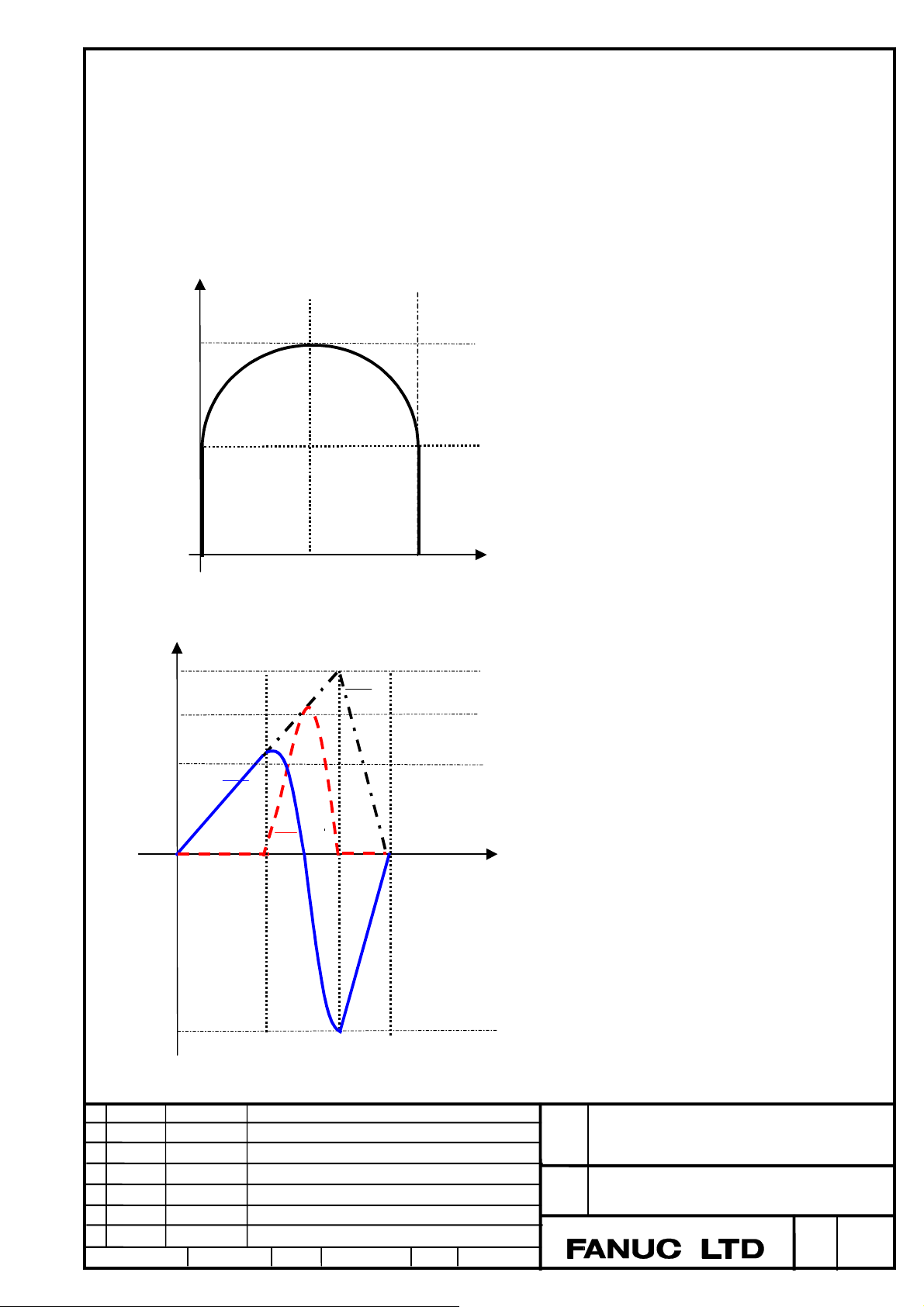
(4) When the axes more than two are interpolated(linear interpolation, circular interpolation)
Tangential speed becomes a speed of the rate feed at the start point and the end point
between blocks, in which linear interpolation was commanded with multi axes.
In case that the movement direction is changed between blocks, the speed of each axis at the end point of previous block does not
correspond with the speed of each axis at the start point of current block.
(Example1) When the continuous blocks of linear interpolation and circular interpolation are commanded with two axes X and Y
N0001 G93.2 G91 G01 Y30. F100;
N0002 G02 X60. R30. F200;
N0003 G01 Y-30. F0;
60.000
30.000
(2)
200
100
F
0
0
Y axis
Tool path of X and Y axis
Tang e ntial Speed
X axis
60.00030.000
X
t
-200
Speed change of X and Y axis
Ed. Date Design Description
Date Design. E.Tanosaki Apprv.
Title
Draw
No.
FANUC Series 30i / 31i / 32i-MODEL B
Rate feed function
B-64484EN/01-01
page
4 / 6
 Loading...