

Page 1

Parameter Manual
B-62630EN/02
FANUC Series 16/18 /160/180 – Model PB
Page 2

• No part of this manual may be reproduced in any form.
• All specifications and designs are subject to change without notice.
The export of this product is subject to the authorization of the government of the country
from where the product is exported.
In this manual we have tried as much as possible to describe all the various matters.
However, we cannot describe all the matters which must not be done, or which cannot be
done, because there are so many possibilities.
Therefore, matters which are not especially described as possible in this manual should be
regarded as ”impossible”.
This manual contains the program names or device names of other companies, some of
which are registered trademarks of respective owners. However, these names are not
followed by or in the main body.
Page 3
PREFACE
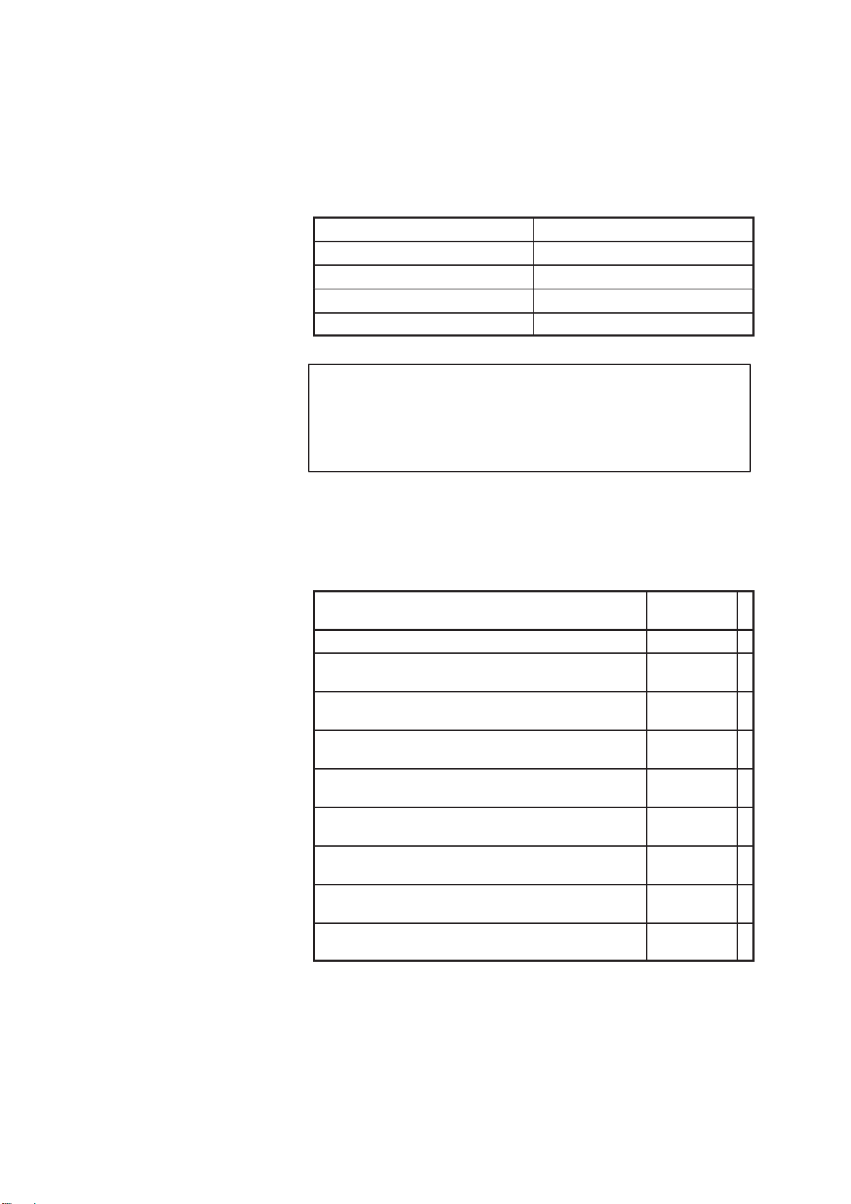
This manual describes the specialized parameters for the following
model:
Product name Abbreviation
FANUC Series 16–PB 16–PB
FANUC Series 18–PB 18–PB
FANUC Series 160–PB 160–PB
FANUC Series 180–PB 180–PB
Note
For details of other parameters, refer to ”Parameter Manual
(B–62450E for the M series).” Note that some functions
cannot be used. For details, refer to ”Descriptions
(B–62622EN for punch press).”
The table below lists the manuals related to MODEL B of the Series 16,
Series 18, Series 160 and Series 180. This manual is indicated by an
asterisk (*).
1 Related Manuals
Manual name
Specification
number
FANUC Series 16/18/160/180–PB DESCRIPTIONS B–62622EN
FANUC Series 16/18/160/180–MODEL B CONNECTION
MANUAL (Hardware)
B–62443E
FANUC Series 16/18/160/180–MODEL B CONNECTION
MANUAL (Function)
B–62443E–1
FANUC Series 16/18/160/180–PB CONNECTION MANUAL (Function)
B–62623EN
FANUC Series 16/18/160/180–PB OPERATOR’S MANUAL
B–62624EN
FANUC Series 16/18/160/180–MODEL B
MAINTENANCE MANUAL
B–62445E
FANUC Series 16/18/160/180–MODEL B
PARAMETER MANUAL
B–62450E
FANUC Series 16/18/160/180–PB PARAMETER MANUAL
B–62630EN
*
FANUC Series 16/18/20/21 PROGRAMMING MANUAL
(Macro Compiler/Macro Executer)
B–61803E–1
Page 4

B–62630EN/02
Table of contents
i
1. PARAMETERS OF THE PRESS FUNCTION 1. . . . . . . . . . . . . . . . . . . . . . . . . . . . . .
2. PARAMETERS FOR THE SPEED AND LOOP GAIN SWITCH 12. . . . . . . . . . . . . . .
3. PARAMETERS FOR THE NIBBLING FUNCTION 22. . . . . . . . . . . . . . . . . . . . . . . . . .
4. PARAMETERS FOR THE PATTERN FUNCTION 25. . . . . . . . . . . . . . . . . . . . . . . . . .
5. PARAMETERS FOR THE PUNCH AND LASER SWITCH 30. . . . . . . . . . . . . . . . . . .
6. PARAMETERS FOR THE TURRET AXIS 31. . . . . . . . . . . . . . . . . . . . . . . . . . . . . . . . .
6.1 PARAMETERS FOR THE FUNCTION USED TO SET TOOL DATA 35. . . . . . . . . . . . . . . .
7. PARAMETERS FOR C-AXIS CONTROL 38. . . . . . . . . . . . . . . . . . . . . . . . . . . . . . . . . .
8. PARAMETERS FOR THE SAFETY ZONE 48. . . . . . . . . . . . . . . . . . . . . . . . . . . . . . . .
9. ADDITIONAL PARAMETERS FOR DI/DO SIGNALS 56. . . . . . . . . . . . . . . . . . . . . . .
10.PARAMETERS FOR CANCELLING Y–AXIS GAP 57. . . . . . . . . . . . . . . . . . . . . . . . .
Page 5

B–62630EN/02
1. PARAMETERS OF THE PRESS FUNCTION
1
1
PARAMETERS OF THE PRESS FUNCTION
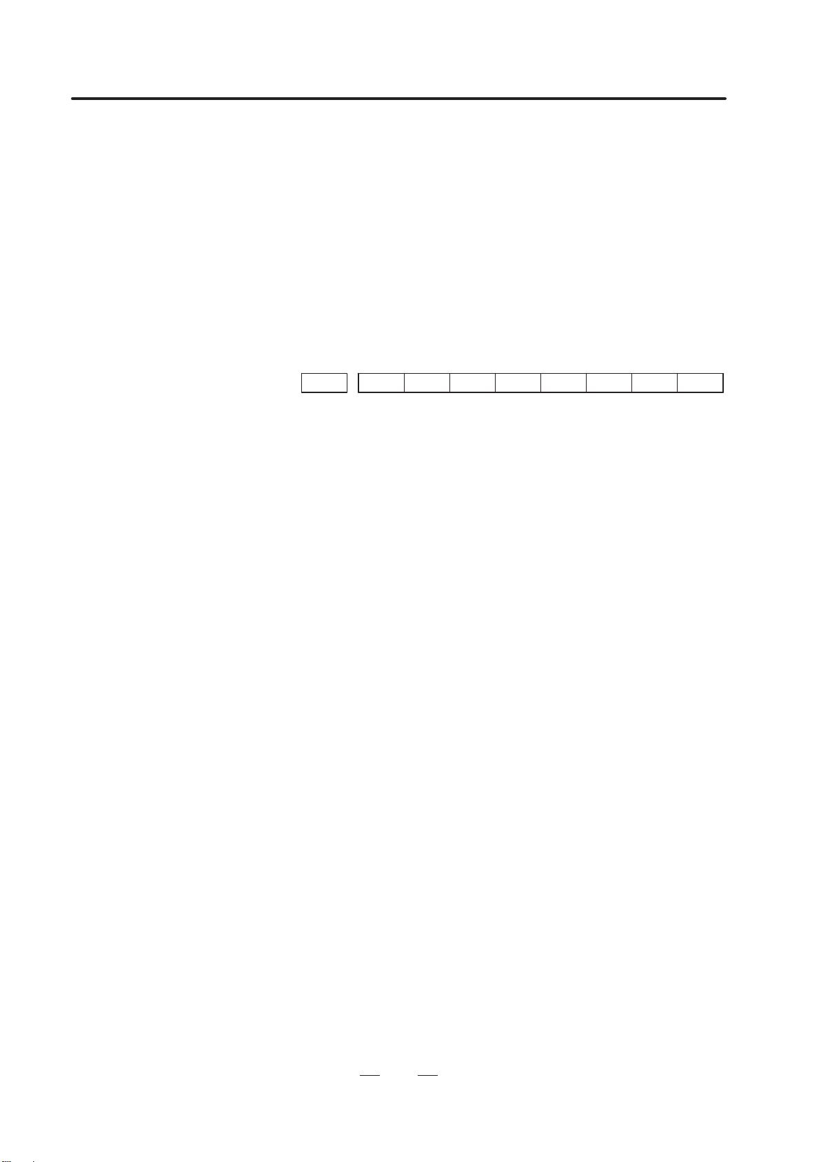
Bit No.
#7 #6 #5 #4 #3 #2 #1 #0Address
16000 PEI NFI PFI RPF HCI HSP
Data type: Bit
HSP High–speed press control is:
0: Disabled.
1: Enabled.
To enable the use of this parameter, the following
conditions must be satisfied:
The PMC–RC function is used.
The following functions cannot be used:
PMC–RB function
Servo waveform display (The correct waveform
cannot be displayed while this function is being used.)
Axis control by PMC (PMC axis cannot be controlled
while this function is being used)
Look–ahead control
HCI Under high–speed press control, the *PFIN signal to complete
punching for single–cycle pressing, and the *NFIN signal to
complete punching for continuous pressing are valid for:
0: Standard address (X1004).
When this is selected, the maximum stop time, from
when the punching complete signal is input until
movement along an axis starts, is 5 msec.
1: High–speed DI address HDI0 (both *PFIN and *NFIN).
When this is selected, the maximum stop time, from
when the punching complete signal is input until
movement along an axis starts, is 3 msec. T o enable the
use of this parameter, the high–speed DI is necessary.
When the high–speed DI is used, set parameter
No.6207#0 (IOC) to 1.
RPF When the RESET key is pressed or when external reset, reset
and rewind, or emergency stop is activated, the PF signal to start
pressing is:
0: Set to 0.
1: Not set to 0.
PF is set to 0 only when the *PE signal to stop pressing is
set to 0.
PFI The logic of the *PFIN signal to complete punching for
single–cycle pressing is:
0: The same as the logic described in the ”Connection
Manual.”
1: The reverse of the logic described in the ”Connection
Manual.”
Page 6

1. PARAMETERS OF THE PRESS FUNCTION
B–62630EN/02
2
NFI The logic of the *NFIN signal to complete punching for
continuous pressing is:
0: The same as the logic described in the “Connection
Manual.”
1: The reverse of the logic described in the “Connection
Manual.”
PEI The logic of the *PE signal to stop pressing is:
0: The same as the logic described in the “Connection
Manual.”
1: The revese of the logic described in the “Connection
Manual.”
Bit No.
#7 #6 #5 #4 #3 #2 #1 #0Address
16001 CPF MPF PMA PSY PE2 PRC PFE MNP
Data type: Bit
MNP If there remains a distance to be traveled when automatic
operation is halted, manual pressing or continuous manual
pressing is:
0: Validated.
1: Invalidated.
PFE When the PF signal to start pressing is set to 1, the absolute
value of positional deviation for the X– and Y– axes:
0: Must be less than or equal to the value set in paramter
1610.
1: Need not be less than or equal to the value set in parameter
1610.
PRC When the machine lock signal, MLK, is set to 1, a program
check is:
0: Not executed.
1: Executed.
The machine position data is updated although the actual
position is not changed. This setting is invalid for the
machine lock signal of each axis.
PE2 To output the PF signal to start pressing, position check is
executed at intervals of:
0: 8 msec.
1: 2 msec.
PSY Under simple synchronous control, the PF signal to start
pressing is output:
0: Irrespective of the machine coordinates of the
synchronous axes.
1: After it has been confirmed that the machine coordinates
of the synchronous axes agree with each other. If the
machine coordinates differ, alarm 213 will be issued and
the PF signal will not be output.
PMA When the AFL signal to lock miscellaneous functions is set to
1, M code signals for forming, repositioning, and nibbling are:
0: Not output to the machine.
1: Output to the machine.
Page 7
B–62630EN/02
1. PARAMETERS OF THE PRESS FUNCTION
3
MPF In a block containing an M code, the PF signal to start pressing
is:
0: Not set to 1.
1: Set to 1.
PF is set to 1 when movement along an axis terminates or
when completion of the miscellaneous function is
returned.
CPF At the end of the 01 group containing the G01, G02, or G03
code, the PF signal to start pressing is:
0: Not set to 1.
1: Set to 1.
Bit No.
#7 #6 #5 #4 #3 #2 #1 #0Address
16002 EUP PF9 PWB SPR PFB PEM
Data type: Bit
PEM MDI operation:
0: Does not start pressing.
1: Starts pressing.
PFB The PFB signal to start pressing is:
0: Enabled.
1: Disabled.
SPR The *SPR signal to halt automatic oparation B is:
0: Invalidated.
1: Validated.
PWB The PFWB signal to wait for the start of pressing B is:
0: Invalidated.
1: Validated.
PF9 The time interval between setting of the PFB signal to start
pressing B to 0 and setting of the PF signal to start pressing to
0 is set to the value in:
0: Parameter 16037.
1: Parameter 16038.
EUP By executing the external operation function, the number of
punching cycles is:
0: Not aggregated.
1: Aggregated.
One is added when the PF signal to start pressing and the
EF signal to external operation are set to 1.
Page 8
1. PARAMETERS OF THE PRESS FUNCTION
B–62630EN/02
4
Bit No.
#7 #6 #5 #4 #3 #2 #1 #0Address
16003 NED DPE TCF
Data type: Bit
TCF After the OP signal indicating that automatic operation is in
progress is set from 0 to 1, the PF signal to start pressing is set
to 1:
0: Only when a T command is found.
This status is the same as the status in which the PFW
signal to wait for the start of pressingis set to 1.
1: Even if no T commands are found.
DPE The relationship between the *PE signal to stop pressing and the
EPE signal for ignoring the signal to stop pressing is as follows:
0: *PE is always validated irrespective of the status of EPE.
1: *PE is validated when EPE is set to 1, and invalidated
when EPE is set to 0.
NED After the last positioning ends in a nibbling block, the PF signal
to start pressing is set to 0:
0: When the contact of the *PE signal to stop pressing is set
to 0.
1: When the two contacts of the *NFIN signal to complete
punching for continuous pressing and the *PE signal stop
pressing are set to 0.
Address
16008 M code for setting the forming mode
16009 M code for canceling the forming mode
Data type: Byte
Valid data range: 1 to 97
Parameter 16008 sets the M code for setting the forming mode.
Parameter 16009 sets the M code for canceling the forming mode.
Address
16010 Upper limit of the position deviation at which PF is set to 1
Data type: Word axis
Unit of data: Units of detection
Valid data range: 0 to 32767
For each axis, parameter 16010 sets the upper limit of the positional
deviation at which the PF signal to start pressing is set to 1. When the
absolute value of the positional deviation does not exceed this highest
limit, PF is set to 1.
Parameter 16010 is validated when parameter PFE (No. 16001, #1) is set
to 1.
Note
The parameter can only be set for the X, Y, and C axes.
Page 9
B–62630EN/02
1. PARAMETERS OF THE PRESS FUNCTION
5
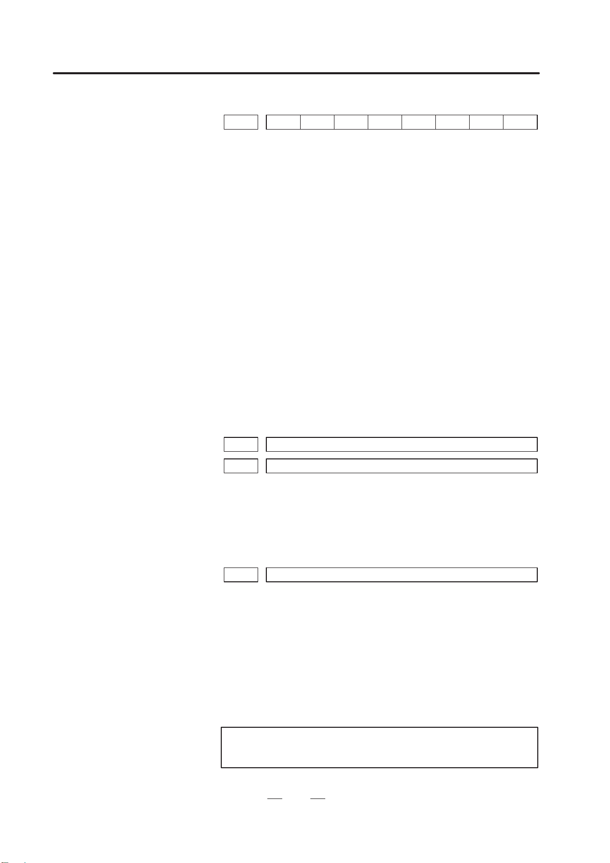
Address
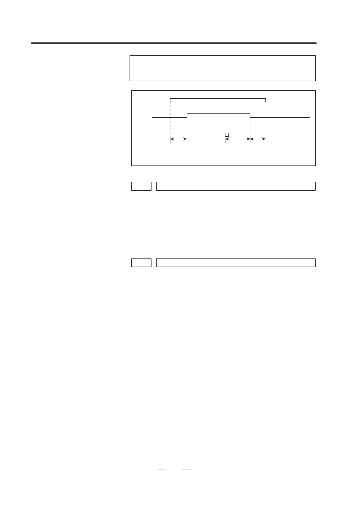
16011 Duration for which the start of positioning is delayed
Data type: Byte axis
Unit of data: msec
Valid data range: 0 to 248
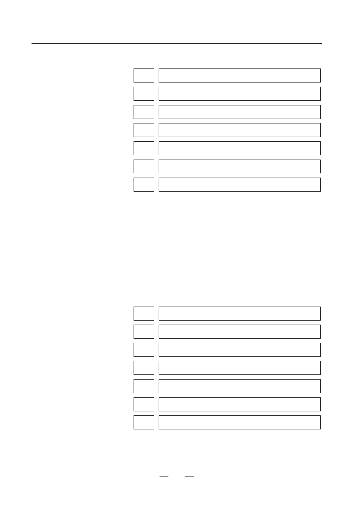
For each axis, parameter 16011 sets the duration for which the start of
positioning is delayed.
Notes
1 Only a multiple of 8 can be set for parameter 16011.
2 The parameter can only be set for the X, Y, and C axes.
Positioning
Time set in parameter 16011
Positioning in the
next block
Address
16012 Time interval by which setting of PF to 1 precedes completion of positioning
Data type: Byte axis
Unit of data: msec
Valid data range: 0 to 248
For each axis, parameter 16012 sets the time interval by which setting of
the PF signal to start pressing to 1 precedes completion of positioning.
(Function to advance setting of the PF signal)
Notes
1 When parameter KLV (No. 16050, #7) is set to 1, the data
is invalidated. If it is invalidated, see the descriptions of
parameters 16–13 to 16026.
2 The parameter can only be set for the X, T, and C axes.
Page 10
1. PARAMETERS OF THE PRESS FUNCTION
B–62630EN/02
6
Address
16013
Time interval by which setting of PF to 1 precedes completion of X–axis
positioning for the distance of level 1
16014
Time interval by which setting of PF to 1 precedes completion of X–axis
positioning for the distance of level 2
16015
Time interval by which setting of PF to 1 precedes completion of X–axis
positioning for the distance of level 3
16016
Time interval by which setting of PF to 1 precedes completion of X–axis
positioning for the distance of level 4
16017
Time interval by which setting of PF to 1 precedes completion of X–axis
positioning for the distance of level 5
16018
Time interval by which setting of PF to 1 precedes completion of X–axis
positioning for the distance of level 6
16019
Time interval by which setting of PF to 1 precedes completion of X–axis
positioning for the distance of level 7
Data type: Byte
Unit of data: msec
Valid data range: 0 to 120
Each of these parameters set the time interval by which setting of the PF
signal to start pressing to 1 precedes completion of X–axis positioning for
the corresponding distance level. (Function to advance setting of PF
signal)
The parameters are validated when parameter KL V (No. 16050, #7) is set
to 1.
For the positioning distance, see the descriptions of parameters 16055 to
16066.
Address
16020
Time interval by which setting of PF to 1 precedes completion of Y–axis
positioning for the distance of level 1.
16021
Time interval by which setting of PF to 1 precedes completion of Y–axis
positioning for the distance of level 2.
16022
Time interval by which setting of PF to 1 precedes completion of Y–axis
positioning for the distance of level 3.
16023
Time interval by which setting of PF to 1 precedes completion of Y–axis
positioning for the distance of level 4.
16024
Time interval by which setting of PF to 1 precedes completion of Y–axis
positioning for the distance of level 5.
16025
Time interval by which setting of PF to 1 precedes completion of Y–axis
positioning for the distance of level 6.
16026
Time interval by which setting of PF to 1 precedes completion of Y–axis
positioning for the distance of level 7.
Data type: Byte
Unit of data: msec
Valid data range: 0 to 120
Page 11
B–62630EN/02
1. PARAMETERS OF THE PRESS FUNCTION
7
Each of these parameters set the time interval by which setting of the PF
signal to start pressing to 1 precedes completion of Y–axis positioning for
the corresponding distance level. (Function to advance setting of PF
signal)
The parameters are validated when parameter KL V (No. 16050, #7) is set
to 1.
For the positioning distance, set the descriptions of data 16055 to 16066.
Address
16027
Time interval by which setting of PF to 1 precedes completion of C–axis
positioning for the distance of level 1.
16028
Time interval by which setting of PF to 2 precedes completion of C–axis
positioning for the distance of level 2.
16029
Time interval by which setting of PF to 3 precedes completion of C–axis
positioning for the distance of level 3.
Data type: Byte
Unit of data: msec
Valid data range: 0 to 120
Each of these parameters set the time intarval by which setting of the PF
signal to start pressing to 1 precedes completion of C–axis positioning for
the corresponding distance level. (Function to advance setting of PF
signal)
The parameters are validated when parameter KLC (No. 16050, #4) is set
to 1.
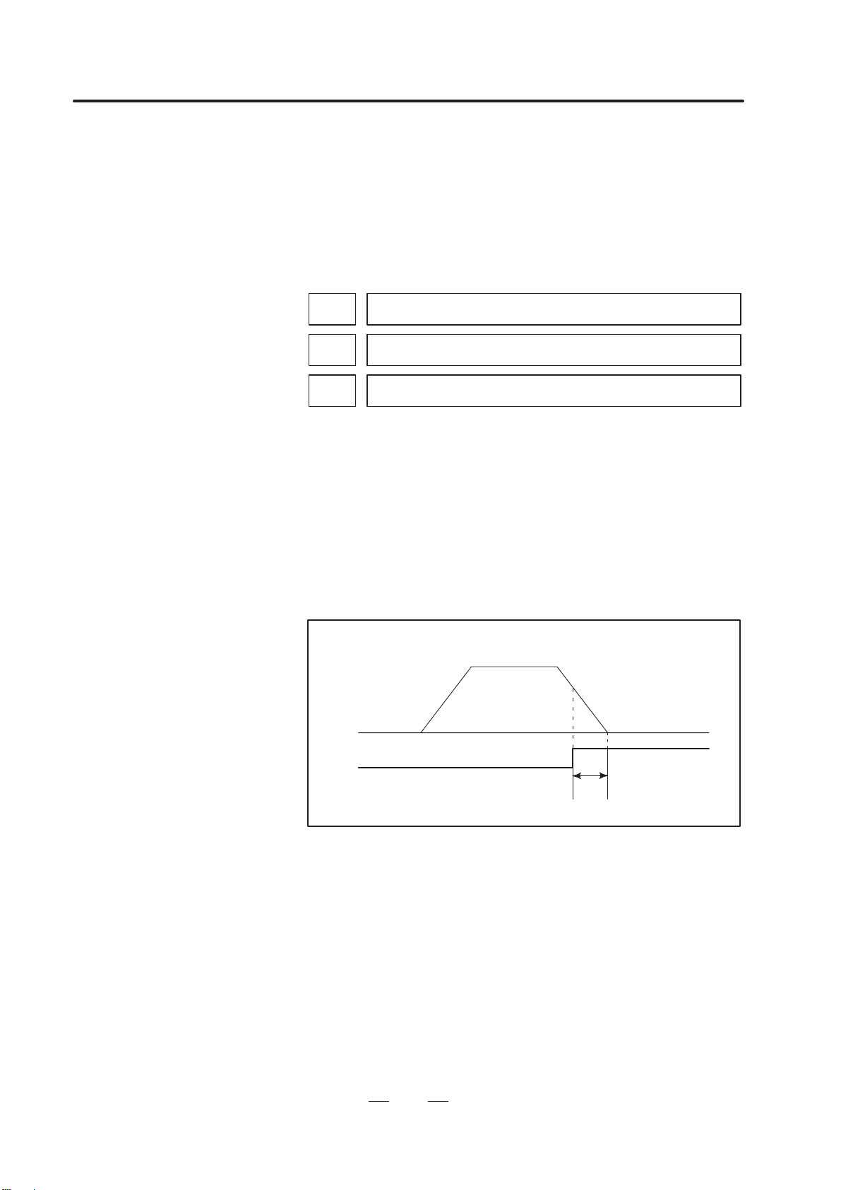
For the positioning distance, see the description of data 16140 and 16141.
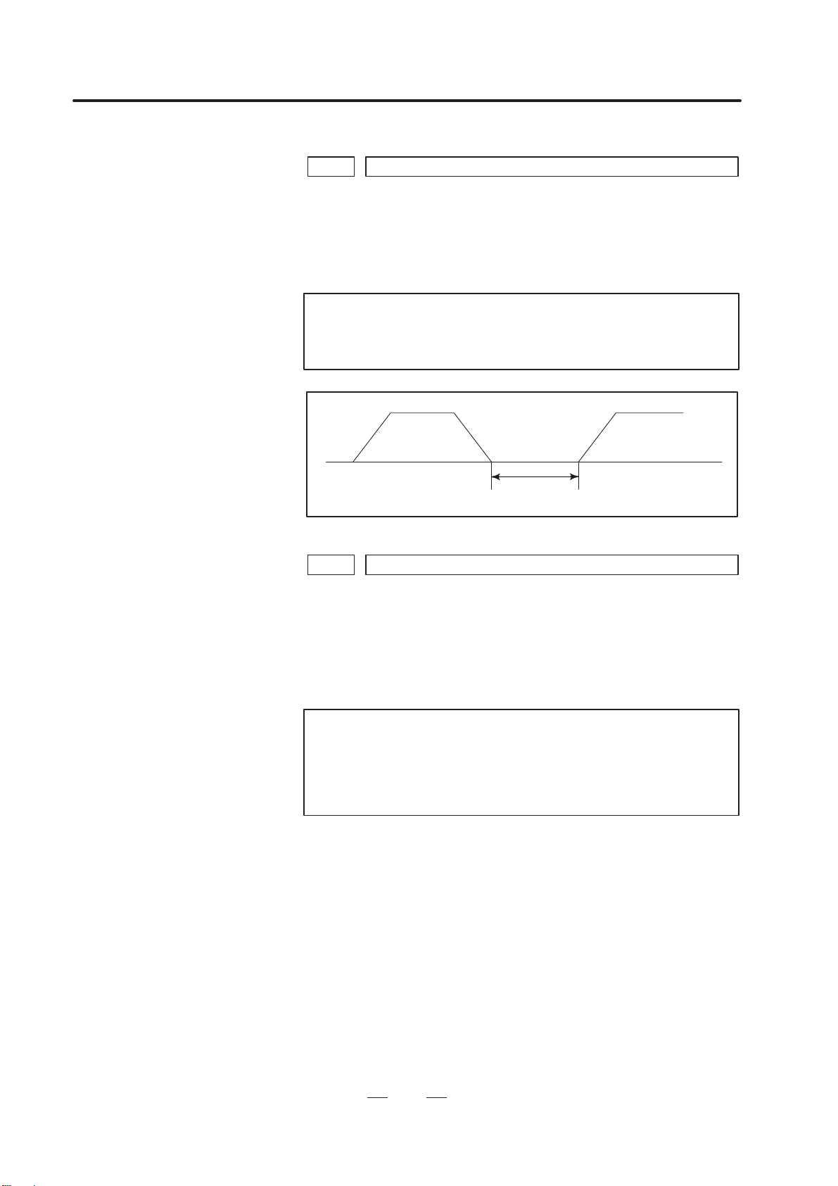
Positioning
Time set in the parameter
PF
(Function to advance setting of PF signal)
If the time set here is longer than the time required for deceleration, the
PF signal is set to1 when decelaration starts.
In simultaneous positioning for the X, Y, and C axes, the PF signal is set
to 1 when the individual conditions for the X, Y, and C axes are all
satisfied.
Page 12
1. PARAMETERS OF THE PRESS FUNCTION
B–62630EN/02
8
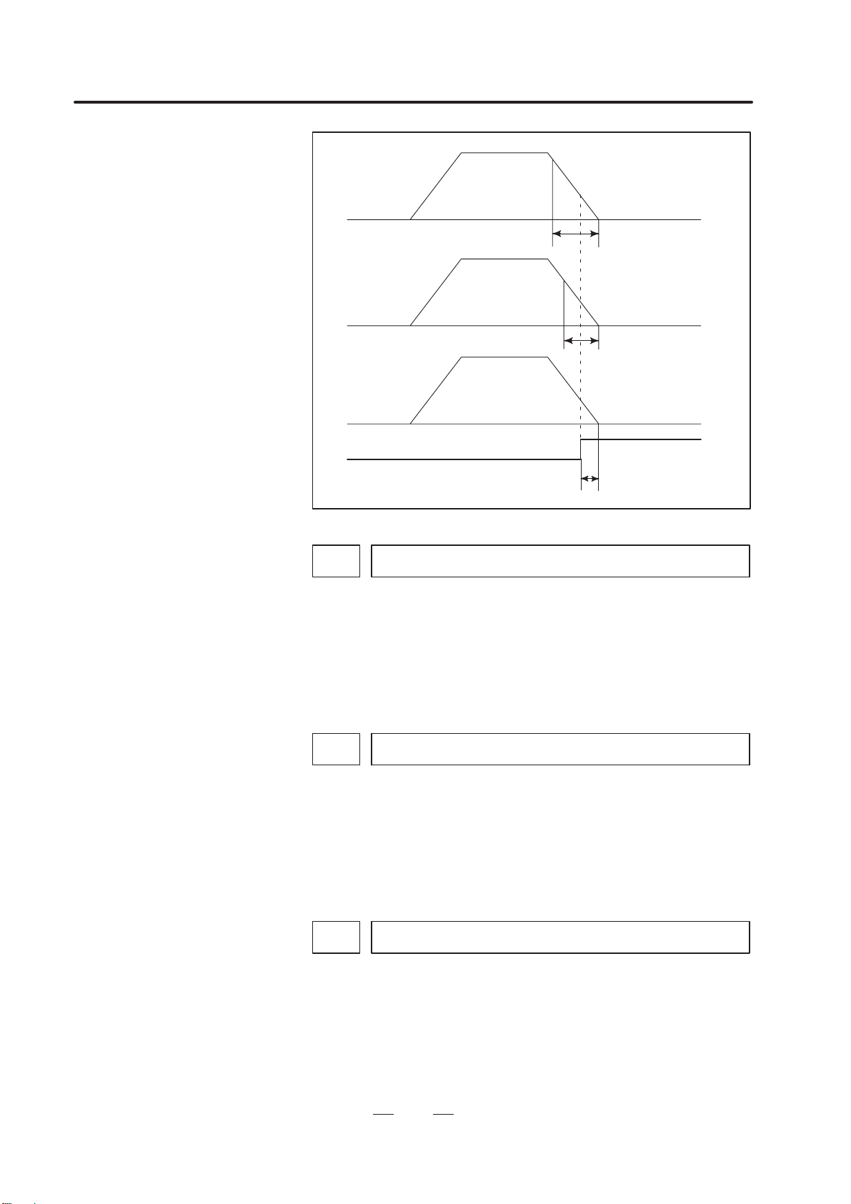
C–axis
positioning
Time set for the C–axis
X–axis
positioning
Y–axis
positioning
Time set for the Y–axis
Time set for the X–axis
PF
Address
16030
Time interval by which setting PF to 0 follows setting *PE to 0 in single–
cycle pressing
Data type: Byte
Unit of data: msec
Valid data range: 0 to 248
Parameter 16030 sets the time interval by which setting the PF signal to
start pressing to 0 follows setting the contact of the *PE signal to stop
pressing to 0 in single–cycle pressing.
Address
16031
Time interval between completion of positioning and the start of the next
block when PFL is set to 1
Data type: Byte
Unit of data: msec
Valid data range: 0 to 248
Parameter 16031 sets the time interval between completion of positioning
and the start of the next block when are PFL signal to lock the start of
pressing is set to 1.
Address
16032
Time interval by which setting of PF to 1 follows positioning in the forming
mode
Data type: Byte
Unit of data: msec
Valid data range: 0 to 248
Parameter 16032 sets the time interval by which setting the PF signal to
start pressing to 1 follows positioning in the forming mode (except for
nibbling).
Page 13

B–62630EN/02
1. PARAMETERS OF THE PRESS FUNCTION
9
Address
16033
Time interval by which the start of the next bolck follows setting of *PFIN to
0 in the forming mode
Data type: Byte
Unit of data: msec
Valid data range: 0 to 248
Parameter 16033 sets the time interval by which the start of the next block
follows setting the contact of the *PFIN signal to complete punching for
single–cycle pressing to 0 in the forming mode.
Positioning
Time set in
parameter
16032
Next block
Time set in
parameter
16033
PF
*PFIN
Address
16034 Time interval by which setting PF to 1 follows first positioning in nibbling
Data type: Byte
Unit of data: msec
Valid data range: 0 to 248
Parameter 16034 sets the time interval by which setting the PF signal to
start pressing to 1 follows positioning at the first punch point in nibbling
(nibbling by G68, G69, and M code).
Address
16035
Time interval by which the start of the next block follows setting *NFIN to 0
at the last positioning in nibbling
Data type: Byte
Unit of data: msec
Valid data range: 0 to 248
Parameter 16035 sets the time interval by which the start of the next block
follows setting the contact of the *NFIN signal to complete punching for
continuous pressing to 0 at positioning at the last punch point in nibbling
(nibbling by G68, G69, and M code).
Page 14
1. PARAMETERS OF THE PRESS FUNCTION
B–62630EN/02
10
Address
16036
Minimum time interval by which setting of PF to 1 follows setting of *PFIN
to 0 in single–cycle pressing
Data type: Byte
Unit of data: msec
Valid data range: 0 to 248
Parameter 16036 sets the minimum time interval by which setting the PF
signal to start pressingto 1 follows setting the contact of the *PFIN signal
to complete punching for single–cycle pressing to 0 in single–cycle
pressing. After the contact of *PFIN is set to 0, PF is set to 1 when the time
set here elapses. PF is not set to 1 even if positioning for the next block
completes and other conditions are satisfied before the time elapses.
Address
16037
Time interval by which setting PFB to 1 follows setting PF to 1 and settiug
PF to 0 follows setting PFB to 0
Data type: Byte
Unit of data: msec
Valid data range: 0 to 20
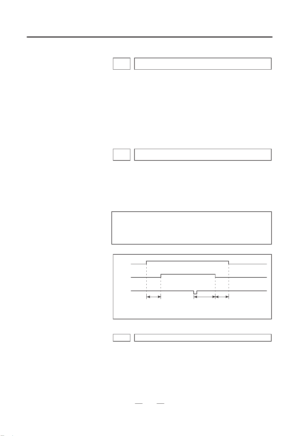
Parameter 16037 sets the time interval by which setting the PFB signal
to start pressing B to 1follows setting the PF signal to start pressing to 1
and setting PF to 0 follows setting PFB to 0.
Notes
1 Only a multiple of 2 can be set for parameter 16037.
2 The parameter must be set to 0 when the PFB signal is not
used.
PF
PFB
*PE
Time set in
parameter
16037
Time set in
parameter
16030
Time set in
parameter
16037
Address
16038 Time interval by which setting PF to 0 follows setting PFB to 0
Data type: Byte
Unit of data: msec
Valid data range: 0 to 20
Parameter 16038 sets the time interval by which setting the PF signal to
start pressing to 0 follows setting the PFB signal to start pressing B to 0.
The data is validated when parameter PF9 (No. 16002, #6) is set to 1.
Page 15
B–62630EN/02
1. PARAMETERS OF THE PRESS FUNCTION
11
Note
Only a multiple of 2 can be set in parameter 16038.
PF
PFB
*PE
Time set in
parameter
16037
Time set in
parameter
16030
Time set in
parameter
16038
Address
16039 Time interval by which setting PF to 0 follows setting *PE to 0 in nibbling
Data type: Byte
Unit of data: msec
Valid data range: 0 to 248
Parameter 16039 sets the time interval by which setting the PF signal to
start pressing to 0 follows setting the contact of the *PE signal to stop
pressing to 0 in nibbing.
Address
16040 Time interval by which the start of the next block follows setting *PFIN to 0
Data type: Byte
Unit of data: msec
Valid data range: 0 to 248
Parameter 16040 sets the time interval by which the start of the next block
follows setting the contact of the *PFIN signal to complete single–cycle
pressing to 0 in a block where the PF signal to start pressing is set to 1
(except for the nibbling or forming mode).
Page 16

2. PARAMETERS FOR THE SPEED AND LOOP GAIN SWITCH
B–62630EN/02
12
2
PARAMETERS FOR THE SPEED AND LOOP GAIN SWITCH
Bit No.
#7 #6 #5 #4 #3 #2 #1 #0Address
16050 KLV PCT CT2 KLC NCT PCF G0F
Data type: Bit
G0F For a rapid traverse command (G00), the X–axis or Y–axis
rapid traverse feedrate is set to the value:
0: Specified in the parameter.
1: Specified by the F code. The maximum feedrate of the F
command is limited to the rapid traverse feedrate in the
parameter. KLV (No. 16050, #7) and LPG (No. 16051, #4)
are valid.
PCF The X–axis or Y–axis movement mode is selected for the
following blocks:
(1) Movement to each punch point with the pattern function
(G26, G76, G77, G78, etc.)
(2) Operation in automatic repositioning (G75)
(3) Movement to the first punch point with the nibbling
function (G68, G69, and M code)
0: Rapid traverse is executed.
1: For G00, rapid traverse is executed. For G01, G02, or G03,
linear interpolation cutting feed is executed.
NCT Constant control of positioning time is:
0: Always enabled.
1: Enabled only when the nibbling command is executed.
This parameter is valid when the PCT bit (bit 6 of
parameter 16050) is set to 1.
KLC When rapid traverse is executed in automatic operation, the
function to change the time constant and C–axis rapid traverse
feedrate among three levels according to the positioning
angleis:
0: Invalidated.
1: Validated. See the descriptions of parameters 16040 to
16147.
CT2 In constant control of the positioning time, the times specified
in parameters 16095 to 16102 are:
0: Not changed.
1: Doubled.
PCT Constant control of positioning time is:
0: Invalidated.
1: Validated. The parameter is validated when parameter
KLV (No. 16050, #7) is set to 1.
See the descriptions of parameters 16095 to 16102.
Page 17

B–62630EN/02
2. PARAMETERS FOR THE SPEED AND LOOP GAIN SWITCH
13
KLV When rapid traverse is executed in automatic operation, the
function to change the time constant and X–axis and Y–axis
rapid traverse feedrates among seven levels according to the
positioning distance is:
0: Invalidated.
1: Validated. See the descriptions of data 16055 to 16094.
Bit No.
#7 #6 #5 #4 #3 #2 #1 #0Address
16051 PGC LPG KLT
Data type: Bit
KLT When rapid traverse is executed in automatic operation, the
function to change the servo loop gain of position control and
time constant of T–axis rapid traverse among three levels
according to the indexed angle is:
0: Invalidated.
1: Validated. See the descriptions of parameters 16177 to
16124.
LPG When rapid traverse is executed in automatic operation, the
function to change the servo loop gain of X–axis and Y–axis
position control among seven levels according to the
positioning distance is:
0: Invalidated.
1: Validated. The parameter is validated when parameter
KLV (No. 16050, #7) is set to 1.
See the descriptions of parameters 16103 to 16116.
PGC Servo loop gains of X–axis and Y–axis position control to be
used in rapid traverse and cutting feed:
0: Are the same.
1: Can be set separately. See the description of parameter
16160.
Page 18

2. PARAMETERS FOR THE SPEED AND LOOP GAIN SWITCH
B–62630EN/02
14
Bit No.
#7 #6 #5 #4 #3 #2 #1 #0Address
16052 TJG TC0 NJC
Data type: Bit
NJC The jog feedrate is:
0: Limited to the manual rapid traverse rate.
1: Not limited to the manual rapid traverse rate.
TC0 For the T or C axis, a rapid traverse override is:
0: Validated.
ROV1 ROV2 T–axis or C–axis override
0 0 100%
1 0 100%
0 1 50%
1 1 50%
1: Invalidated. (The rapid traverse override is always 100%.)
TJG The jog override signals for the T–axis and C–axis (G233, #0
and #1) are:
0: Not used.
1: Used.
*JVT1 *JVT2 T–axis or C–axis override
1 1 25%
1 0 50%
0 1 75%
0 0 100%
Bit No.
#7 #6 #5 #4 #3 #2 #1 #0Address
16054 2MPj
Data type: Bit axis
2MPj Specifies the acceleration/deceleration duration for a rapid
traverse command.
0: 8 ms
1: 2 ms
(1) This function can be set for each axis. FANUC, however, advises
against setting this function for more than four axes. If this function
is set for more than four axes, the operability and CNC processing
speed may be degraded considerably, depending on other specified
options. In such a case, normal control cannot be guaranteed.
(2) This function cannot be used together with the look–ahead control
function.
(3) Servo waveform data is displayed in 8 ms cycles.
Page 19
B–62630EN/02
2. PARAMETERS FOR THE SPEED AND LOOP GAIN SWITCH
15
Address
16055 Distance D1 to level 1 (in mm)
16056 Distance D2 to level 2 (in mm)
16057 Distance D3 to level 3 (in mm)
16058 Distance D4 to level 4 (in mm)
16059 Distance D5 to level 5 (in mm)
16060 Distance D6 to level 6 (in mm)
Address
16061 Distance D1 to level 1 (in inches)
16062 Distance D2 to level 2 (in inches)
16063 Distance D3 to level 3 (in inches)
16064 Distance D4 to level 4 (in inches)
16065 Distance D5 to level 5 (in inches)
16066 Distance D6 to level 6 (in inches)
Data type: Two–word
Unit of data:
Increment system IS–A IS–B Units
Input in milimeters 0.01 0.001 mm
Input in inches 0.001 0.0001 inch
Valid data range: 0 to 99999999
Each of the parameters set the positioning distance to use the function to
change the time constant and X–axis and Y–axis rapid traverse feedrate
among seven levels according to the positioning distance. (Identical
values are set for the X and Y axes.)
The data is validated when parameter KLV (No. 16050, #7) is set to 1.
Notes
1 The values set here must satisfy the following relationship:
D1 < D2 < D3 < D4 < D5 < D6.
2 The values can be changed among seven levels or less.
When the values are to be changed among four levels, set
D4 to 99999999.
Page 20
2. PARAMETERS FOR THE SPEED AND LOOP GAIN SWITCH
B–62630EN/02
16
Address
16067 X–axis rapid traverse feedrate of level 1
16068 X–axis rapid traverse feedrate of level 2
16069 X–axis rapid traverse feedrate of level 3
16070 X–axis rapid traverse feedrate of level 4
16071 X–axis rapid traverse feedrate of level 5
16072 X–axis rapid traverse feedrate of level 6
16073 X–axis rapid traverse feedrate of level 7
Data type: Two–word
Unit of data:
Valid data range:
Increment system Units of data Valid data range
Millimeter machine 1 mm/min 30 to 240000
Inch machine 0.1 inch/min 30 to 96000
Each of the parameters set the X–axis rapid traverse feedrate for the
corresponding distance.
See the descriptions of parameters 16055 to 16066.
Address
16074 X–axis rapid traverse time constant of level 1
16075 X–axis rapid traverse time constant of level 2
16076 X–axis rapid traverse time constant of level 3
16077 X–axis rapid traverse time constant of level 4
16078 X–axis rapid traverse time constant of level 5
16079 X–axis rapid traverse time constant of level 6
16080 X–axis rapid traverse time constant of level 7
Data type: Word
Unit of data: msec
Valid data range: 8 to 4000
Each of the parameters set the X–axis rapid traverse time constant for the
corresponding positioning distance.
See the descriptions of parameters 16055 to 16066.
Page 21

B–62630EN/02
2. PARAMETERS FOR THE SPEED AND LOOP GAIN SWITCH
17
Address
16081 Y–axis rapid traverse feedrate of level 1
16082 Y–axis rapid traverse feedrate of level 2
16083 Y–axis rapid traverse feedrate of level 3
16084 Y–axis rapid traverse feedrate of level 4
16085 Y–axis rapid traverse feedrate of level 5
16086 Y–axis rapid traverse feedrate of level 6
16087 Y–axis rapid traverse feedrate of level 7
Data type: Two–word
Unit of data:
Valid data range:
Increment system Units of data Valid data range
Millimeter machine 1 mm/min 30 to 240000
Inch machine 0.1 inch/min 30 to 96000
Each of the parameters set the Y–axis rapid traverse feedrate for the
corresponding distance.
See the descriptions of parameters 16055 to 16066.
Address
16088 Y–axis rapid traverse time constant of level 1
16089 Y–axis rapid traverse time constant of level 2
16090 Y–axis rapid traverse time constant of level 3
16091 Y–axis rapid traverse time constant of level 4
16092 Y–axis rapid traverse time constant of level 5
16093 Y–axis rapid traverse time constant of level 6
16094 Y–axis rapid traverse time constant of level 7
Data type: Word
Unit of data: msec
Valid data range: 8 to 4000
Each of the parameters set the Y–axis rapid traverse time constant for the
corresponding positioning distance.
See the descriptions of parameters 16055 to 16066.
Page 22

2. PARAMETERS FOR THE SPEED AND LOOP GAIN SWITCH
B–62630EN/02
18
Relationship between positioning distances and data numbers
X–axis Y–axis
Level
Positioning
distance
d
Rapid
traverse
feedrate
Rapid tra-
verse time
constant
Rapid
traverse
feedrate
Rapid tra-
verse time
constant
1 0<dD1 16067 16074 16081 16088
2 D1<dD2 16068 16075 16082 16089
3 D2<dD3 16069 16076 16083 16090
4 D3<dD4 16070 16077 16084 16091
5 D4<dD5 16071 16078 16085 16092
6 D5<dD6 16072 16079 16086 16093
7 D6<d 16073 16080 16087 16094
Address
16095 X–axis positioning time of level 1 (Rapid traverse override of 100% or 75%)
16096 X–axis positioning time of level 1 (Rapid traverse override of 50% or 25%)
16097 X–axis positioning time of level 2 (Rapid traverse override of 100% or 75%)
16098 X–axis positioning time of level 2 (Rapid traverse override of 50% or 25%)
Address
16099 Y–axis positioning time of level 1 (Rapid traverse override of 100% or 75%)
16100 Y–axis positioning time of level 1 (Rapid traverse override of 50% or 25%)
16101 Y–axis positioning time of level 2 (Rapid traverse override of 100% or 75%)
16102 Y–axis positioning time of level 2 (Rapid traverse override of 50% or 25%)
Data type: Byte
Unit of data: msec
Valid data range: 32 to 248
When constant control of the positioning time is applied, each of the
parameters set the X–axisor Y–axis positioning time for the positioning
distance of level one or two.
The parameters are validated when parameter KLV (No. 16050, #7) and
PCT (No. 16050, #6) are set to 1.
Note
When this function is used, parameters 16067, 16068,
16074, 16075, 16081, 16082, 16088, and 16089 are
invalidated. Constant control of the positioning time is
applied, irrespective of the positioning distance.
Page 23

B–62630EN/02
2. PARAMETERS FOR THE SPEED AND LOOP GAIN SWITCH
19
Address
16103 X–axis servo loop gain of level 1
16104 X–axis servo loop gain of level 2
16105 X–axis servo loop gain of level 3
16106 X–axis servo loop gain of level 4
16107 X–axis servo loop gain of level 5
16108 X–axis servo loop gain of level 6
16109 X–axis servo loop gain of level 7
Data type: Word
Unit of data: 0.01 sec
–1
Valid data range: 1 to 9999
Each of the parameters set the servo loop gain of X–axis position control
for the corresponding positioning distance.
See the descriptions of parameters 16055 to 16066.
Address
16110 Y–axis servo loop gain of level 1
16111 Y–axis servo loop gain of level 2
16112 Y–axis servo loop gain of level 3
16113 Y–axis servo loop gain of level 4
16114 Y–axis servo loop gain of level 5
16115 Y–axis servo loop gain of level 6
16116 Y–axis servo loop gain of level 7
Data type: Word
Unit of data: 0.01 sec
–1
Valid data range: 1 to 9999
Each of the parameters set the servo loop gain of Y–axis position control
for the corresponding positioning distance.
See the descriptions of parameters 16055 to 16066.
Address
16117 T–axis angle to level 1
16118 T–axis angle to level 2
Data type: Word
Unit of data: 0.1 deg
Valid data range: 0 to 3600
Each of the parameters set the indexed angle to use the function for
changing the T–axis rapid traverse time constant and servo loop gain of
position control among three levels according to the indexed angle.
The parameters are validated when parameter KL T (No. 16051, #3) is set
to 1.
Page 24

2. PARAMETERS FOR THE SPEED AND LOOP GAIN SWITCH
B–62630EN/02
20
Note
The value of level one must be smaller than the value of
level 2.
Address
16119 T–axis rapid traverse time constant of level 1
16120 T–axis rapid traverse time constant of level 2
16121 T–axis rapid traverse time constant of level 3
Data type: Word
Unit of data: msec
Valid data range: 8 to 4000
Each of the parameters set the T–axis rapid traverse time constant to use
the function for changing the T–axis rapid traverse time constant and
servo loop gain of position control among three levels according to the
indexed angle.
See the descriptions of parameters 16117 and 16118.
Address
16122 T–axis servo loop gain of level 1
16123 T–axis servo loop gain of level 2
16124 T–axis servo loop gain of level 3
Data type: Word
Unit of data: 0.01 sec
–1
Valid data range: 1 to 9999
Each of the parameters set the servo loop gain of T–axis position control
to use the function for changing the T–axis rapid traverse time constand
and servo loop gain of position control among three levels according to
the indexed angle.
See the descriptions of parameters 16117 and 16118.
Address
16140 C–axis angle to level 1
16141 C–axis angle to level 2
Data type: Two–word
Unit of data: 0.01 deg (IS–A)/0.001 deg (IS–B)
Valid data range: 0 to 99999999
Each of the paramters set the positioning angle to use the function for
changing the C–axis rapid traverse feedrate and time constant among
three levels according to the positioning angle.
The data is validated when parameter KLC (No. 16050, #4) is set to 1.
Note
The value of level 1 must be smaller than the value of level
2.
Page 25

B–62630EN/02
2. PARAMETERS FOR THE SPEED AND LOOP GAIN SWITCH
21
Address
16142 C–axis rapid traverse feedrate of level 1
16143 C–axis rapid traverse feedrate of level 2
16144 C–axis rapid traverse feedrate of level 3
Data type: Two–word
Unit of data: 1 deg/min
Valid data range: 30 to 240000
Each of the parameters set the C–axis rapid traverse feedrate to use the
function for changing the C–axis rapid traverse feedrate and rapid traverse
time constant among tree levels according to the positioning angle.
See the descriptions of parameters 16140 and 16141.
Address
16145 C–axis rapid traverse time constant of level 1
16146 C–axis rapid traverse time constant of level 2
16147 C–axis rapid traverse time constant of level 3
Data type: Word
Unit of data: msec
Valid data range: 8 to 4000
Each of the parameters set the C–axis rapid traverse to use the function
for changing the C–axis rapid traverse feedrate and rapid traverse time
constant among three levels according to the positioning angle.
See the descriptions of parameters 16140 and 16141.
Address
16160 Servo loop gain in cutting feed
Data type: Word axis
Unit of data: 0.01 sec
–1
Valid data range: 1 to 9999
For each axis, the parameter sets the servo loop gain of position control
in cutting feed.
The parameter is validated when parameter PGC (No. 16051, #7) is set
to 1.
Note
The parameter can only be set for the X and Y axes.
Page 26

3. PARAMETERS FOR THE NIBBLING FUNCTION
B–62630EN/02
22
3
PARAMETERS FOR THE NIBBLING FUNCTION
Bit No.
#7 #6 #5 #4 #3 #2 #1 #0Address
16181 NSP NPC NMG
Data type: Bit
NMG When the M code for canceling the nibbling mode (No. 16184)
is specified, the G code in the 01 group is:
0: Not changed.
1: Changed to G00 (rapid traverse).
NPC The function to change maximum pitch in the nibbling mode
between two levels is:
0: Not used.
1: Used. The function can be executed by the SNP signal for
changing nibbling between two levels or by the M code
(No. 16185).
NSP When the *SP signal to halt automatic operation is set to 0 in
nibbling, automatic operation is:
0: Decelerated and halted immediately.
1: Halted after positioning for a nibbling pitch completes.
Address
16183 M code for setting the nibbling mode
16184 M code for canceling the nibbling mode
Data type: Byte
Valid data range: 1 to 255
Parameter 16183 sets the M code for setting the nibbling mode.
Address
16185
M code for setting the nibbling mode in which nibbling is changed between
two levels
Data type: Byte
Valid data range: 1 to 255
Parameter 16185 sets the M code for setting the nibbling mode in which
nibbling is changed between two levels.
The data is validated when parameter NPC (No. 16181, #1) is set to 1.
Note
The M code in parameter 16184 is used to cancel the
nibbling mode if set.
Page 27

B–62630EN/02
3. PARAMETERS FOR THE NIBBLING FUNCTION
23
Address
16186 Maximum pitch for G68 or G69 (in mm)
16187 Maximum pitch for G68 or G69 (in inches)
Data type: Two–word
Unit of data:
Increment system IS–A IS–B Units
Input in millmeters 0.01 0.001 mm
Input in inches 0.001 0.0001 inch
Valid data range: 1 to 99999999
Each of the parameters specifies the maximum pitch that can be specified
with G01, G02, or G03 for nibbling by G68 or G69 or by an M code.
Address
16188 Maximum pitch for nibbling by the M code (in mm)
16189 Maximum pitch for nibbling by the M code (in inches)
Data type: Two–word
Unit of data:
Increment system IS–A IS–B Units
Input in millmeters 0.01 0.001 mm
Input in inches 0.001 0.0001 inch
Valid data range: 1 to 99999999
Each of the parameters set the maximum pitch for nibbling by the M code
(No. 16183).
Address
16190
Maximum pitch of the G01, G02 or G03 command for changing nibbling
between two levels (in mm)
16191
Maximum pitch of the G01, G02 or G03 command for changing nibbling
between two levels (in inches)
Data type: Two–word
Unit of data:
Increment system IS–A IS–B Units
Input in millmeters 0.01 0.001 mm
Input in inches 0.001 0.0001 inch
Valid data range: 1 to 99999999
When nibbling by the M code (No. 16185) is executed or the SNP signal
for changing nibbling between two levels is set to 1 while the function for
changing nibbling between two levels is used,each of the parameters set
the maximum nibbling pitch for the G01, G02, or G03 command.
The parameters are validated when parameter NPC (No.16181, #1) is set
to 1.
Page 28

3. PARAMETERS FOR THE NIBBLING FUNCTION
B–62630EN/02
24
Address
16192
Maximum pitch of G00 command for changing nibbling between two levels
(in mm)
16193
Maximum pitch of G00 command for changing nibbling between two levels
(in inches)
Data type: Two–word
Unit of data:
Increment system IS–A IS–B Units
Input in millmeters 0.01 0.001 mm
Input in inches 0.001 0.0001 inch
Valid data range: 1 to 99999999
When nibbling by the M code (No. 16185) is executed or the SNP signal
for changing nibbling between two levels is set to 1 while the function for
changing nibbling between two levels is used,each of the parameters sets
the maximum nibbling pitch for the G00 command.
The data is validated when parameter NPC (No.16181, #1) is set to 1.
Address
16194 Maximum distance traveled along C–axis in nibbling
Data type: Two–word
Unit of data: 0.01 deg (IS–A)/0.001 deg (IS–B)
Valid data range: 1 to 99999999
The parameter sets the maximum distance traveled along the C–axis for
G68 and the nibbling mode.
Page 29

B–62630EN/02
4. PARAMETERS FOR THE PATTERN FUNCTION
25
4
PARAMETERS FOR THE PATTERN FUNCTION
Bit No.
#7 #6 #5 #4 #3 #2 #1 #0Address
16200 UVW ABM MUR UVC
Data type: Bit
UVC In the reset status, the macro stored under a U or V macro
number is:
0: Deleted.
1: Not deleted.
Note
When the parameter is set to 1, two or more macros with
identical numbers may often be stored. It takes a long time
to process the storage of macros.
MUR U or V macro numbers are handled:
0: According to the standard specifications.
1: According to the following specifications.
(1) Changing a macro number
Storage and execution: U01 to U69 and U90 to U99
Storage: U70 to U79
Representation of several macros: U80 to U89
(2) Macro numbers are handled in the same way as when
parameter 16206 of the G73 or G74 command for
taking multiple workpieces is set to 2.
Note
Parameter 16206 is invalidated.
ABM To store and call a pattern, addresses A and B:
0: Are used.
1: Are not used. (The A and B axes can be used.)
UVW To execute a macro function, addresses U, V, and W:
0: Are used.
1: Are not used. (The U, V, and W axes can be used.)
Page 30

4. PARAMETERS FOR THE PATTERN FUNCTION
B–62630EN/02
26
Bit No.
#7 #6 #5 #4 #3 #2 #1 #0Address
16201 MSA AWP IPA APR MLP MPC LIP
Data type: Bit
LIP In the block immediately following setting a local coordinate
system (G52), an incremental command specifies an
incremental value from:
0: The origin of the local coordinate system.
1: The current tool position.
MPC When the number of machined workpieces is counted in
multiple–workpiece machining:
0: The number of actually machined workpieces is counted.
1: The number is incremented by one when complete
machining or remainder machining is executed (but not
when trial machining is executed).
MLP Setting for taking multiple workpieces depends on:
0: The set parameter (No.16206).
1: A signal (MLP1 or MLP2) input from the PMC machine.
APR Upon reset, the repositioning compensation value is:
0: Not cleared.
1: Added to the workpiece coordinate system and cleared.
IP A Although positioning is to be executed in the block immediately
following execution of the pattern function (including G68 or
G69), only a command for either the X– or Y–axis is specified.
Movement to the pattern reference point:
0: Is not executed for the axis which is not specified.
1: Is executed for the axis which is not specified.
AWP When a workpiece coordinate system is specified, automatic
coordinate system setting is executed as designed for:
0: The FANUC Series 16.
When manual return to the reference position is
completed, the origin of the coordinate system is shifted
by the amount set for the selected workpiece coordinate
system (G54 to G59).
1: The FANUC Series 0–P.
When manual return to the reference position is
completed, the coordinates of the automatic coordinate
system setting are shifted by the amount set for the
selected workpiece coordinate system (G54 to G59).
MSA When the MUR bit (bit 5 of parameter 16200) is set to 1, the
machining pattern set for multiple–workpiece machining is:
0: Disabled. When this is selected, the value of parameter
16206 is always assumed to be 2.
1: Enabled.
Page 31

B–62630EN/02
4. PARAMETERS FOR THE PATTERN FUNCTION
27
Bit No.
#7 #6 #5 #4 #3 #2 #1 #0Address
16202 AIP
Data type: Bit
AIP Specifies the condition for the share–proof command (G86).
0: Alarm 4506 is issued when I y 1.5P (l y 1.5wl).
(Conventional specification)
1: Alarm 4506 is issued when I y P (l y wl).
Bit No.
#7 #6 #5 #4 #3 #2 #1 #0Address
16203 ACD PCU
Data type: Bit
PCU The number of machined workpieces is:
0: Counted by an MDI command.
1: Not counted by an MDI command.
ACD A program block causing a PS alarm is:
0: Not displayed.
1: Displayed.
See the description of parameter 16229.
Bit No.
#7 #6 #5 #4 #3 #2 #1 #0Address
16204 PDG BKR
Data type: Bit
BKR The first automatic repositioning command (G75) that sets
automatic operation signal OP from 0 to 1 uses:
0: The values set in parameters 16209 and 16210 as the
clearance and amount of return for the Y–axis.
(The clearance and amount of return are identical values.)
1: The values set in parameters 16209 and 16210 as the
clearance for the Y–axis, and the values set in parameters
16211 and 16212 as the amount of return.
(The clearance and amount of return are different values.)
PDG On the graphic screen, a program being drawn is:
0: Not displayed.
1: Displayed.
This parameter is invalid when the 9–inch CRT is being
used.
Address
16206 Machining pattern when multiple workpieces are taken
Data type: Byte
Valid data range: 0 to 3
Parameter 16206 sets a machining pattern when multiple workpieces are
taken.
0: A program without the G73 or G74 command for
machining when multiple workpieces are taken is used.
Page 32

4. PARAMETERS FOR THE PATTERN FUNCTION
B–62630EN/02
28
Note
Alarm 4539 is issued if the G73 or G74 command is found
with this setting.
1: A program containing the G73 or G74 command is used
and test machining is executed.
2: A program containing the G73 or G74 command is used
and the remaining processing is executed after test
machining.
3: A program containing the G73 or G74 command is used
and the entire machining is executed.
Address
16207 M code for clamping a workpiece
16208 M code for releasing the workpiece
Data type: Byte
Valid data range: 1 to 255
Parameter 16207 sets the M code for clamping a workpiece. Parameter
16208 sets the M code for releasing the workpiece.
In blocks between the M code for clampling a workpiece and the M code
for releasing the workpiece, the distances traveled along the X–axis and
Y–axis are not take into account in the workpiece coordinate system. The
PF signal to start pressing is not set to 1.
Address
16209
Clearance and amount of return for the Y axis in automatic repositioning (in
mm)
16210
Clearance and amount of return for the Y axis in automatic repositioning (in
inches)
Data type: Two–word
Unit of data:
Increment system IS–A IS–B Units
Input in millmeters 0.01 0.001 mm
Input in inches 0.001 0.0001 inch
Valid data range: 1 to "99999999
Each of the parameters sets the clearance and amount of return for the
Y–axis in automatic repositioning (G75).
Address
16211
Amount of return for the Y–axis in automatic repositioning (G75, in millimeters)
16212 Amount of return for the Y–axis in automatic repositioning (G75, in inches)
Data type: Two–word
Unit of data:
Page 33

B–62630EN/02
4. PARAMETERS FOR THE PATTERN FUNCTION
29
Increment system IS–A IS–B Units
Input in millmeters 0.01 0.001 mm
Input in inches 0.001 0.0001 inch
Valid data range: 1 to "99999999
These parameters specify the amount of return for the Y–axis in automatic
repositioning (G75).
The clearance is specified in conventional parameters 16209 and 16210.
These parameters are valid when the BKR bit (bit 2 of parameter 16204)
is set to 1.
Address
16228 Number of characters that can be stored for a U or V macro function
Data type: Byte
Valid data range:
Setting value
Number of macro storage characters
0 3200
1 1 1008
2 22272
3 27072
The 16–PB does not use part program storage as a storage area. The
program area need not be cleared after the setting has been changed.
Address
16229 Color code setting for alarm block display
Data type: Byte
Valid data range: 0 to 3
Setting value
Alarm color
1 Red
2 Green
3 Yellow
4 Blue
5 Pink
6 Light blue
7 White
Others Pink
This parameter specifies the color code in which a program block causing
a PS alarm is displayed. A block causing an overtravel or servo alarm is
not displayed.
Page 34

5. PARAMETER FOR PUNCH AND LASER SWITCH
B–62630EN/02
30
5
PARAMETERS FOR THE PUNCH AND LASER SWITCH
#7 #6 #5 #4 #3 #2 #1 #0Address
16240 RLM ALA
Data type: Bit
ALA Switching between the punching mode and laser mode is:
0: Invalidated.
1: Validated.
RLM When the power is turned on or in the clear status, the machine
is set in the:
0: Punching mode.
1: Leser mode.
#7 #6 #5 #4 #3 #2 #1 #0Address
16241 ILM
Data type: Bit
ILM In a block other than cutting feed blocks or blocks between the
two cutting feed blocks when the laser mode is selected, the next
block is started:
0: After the following is checked: The specified speed is
reduced to zero and the machine reaches the specified
position. (A position check is carried out.)
1: After checking that the specified speed is reduced to zero.
(No position check is carried out.)
The parameters are validated when parameter ALA (No.
16240, #0) is set to 1.
In punching mode, the NCI bit (bit 5 of parameter 1601)
is valid.
Address
16244 M code for setting the punching mode
16245 M code for setting te leser mode
Data type: Byte
Valid data range: 0 to 255
Each of the parameters set the M code for setting the punching mode or
leser mode.
The parameters are validated when parameter ALA (No. 16240, #0) is set
to 1.
Page 35

B–62630EN/02
6. PARAMETERS FOR THE TURRET AXIS
31
6
PARAMETERS FOR THE TURRET AXIS
#7 #6 #5 #4 #3 #2 #1 #0Address
16260 TLP TNM TCL BST
Data type: Bit
BST The function used to output a T code beforehand is:
0: Disabled.
1: Enabled.
TCL The T axis is:
0: Not controlled by the CNC machine.
1: Controlled the CNC machine.
TNM When machine lock signal MLK and the TNG signal for
ignoring a T command are on, whether the number following
address T is cataloged as a tool number is:
0: Not checked.
1: Checked.
Note
Generally, the tool number is not checked when the TNG
signal is set to 1.
TLP In positioning by the T–axis command, a shift from the current
position to a specified position is executed:
0: In the direction in which required rotation angle is smaller.
1: Linearly .
Note
The parameters are validated when parameter TCL (No.
16260 #4) is set to 1.
Page 36

6. PARAMETERS FOR THE TURRET AXIS
B–62630EN/02
32
#7 #6 #5 #4 #3 #2 #1 #0Address
16262 MBT DTF TNA TND TDP PWT JGT NTD
Data type: Bit
NTD The tool data input screen is:
0: Displayed.
1: Not displayed.
JGT On the position display screen in jog mode, a T code (tool
number) is:
0: Not displayed by a signal input from the PMC.
1: Displayed by a signal (addresses G234 to G237) input
from the PMC.
PWT When the power is turned on, the T code (tool number) on the
position display screen is:
0: Set to 0.
1: Represented by signal input from the PMC machine
(addresses G234 to G237).
TDP On the position screen, a T code is:
0: Not displayed.
1: Displayed.
This parameter is valid when the TCL bit (bit 4 of
parameter 16260) is set to 1 and when the NDPx bit (bit
0 of parameter 3115) is set to 0.
TND When the T–axis position is displayed,
0: The current position is indicated in units of minimum
travel increments.
1: The number of the tool at the current position is indicated.
This is validated when TDP (No. 16262, #3) is set to 1.
TNA When a tool number which is not cataloged is specified,
0: Alarm 4692 is issued.
1: No alarm are issued but a T code is output. This must be
specified when a T code with five or more digits is
specified and TCL (No. 16260, #4) is set to 1.
DTF When T codes are specified in automatic operation, a TF signal
for reading the code of the tool function and the tool function
code signal are output:
0: For each T code.
1: For the first T code command when the machine enters the
status in which automatic operation is started from the
status in which automatic operation is halted or stopped.
For the second and subsequent T code commands
specified until the machine returns to the status in which
automatic operation is halted or stopped, the TF signal and
tool function code signal are output only when the T code
signal is different from the previous one.
MBT In a block in which a T code is specified, buffering is:
0: Executed.
1: Not executed.
Page 37

B–62630EN/02
6. PARAMETERS FOR THE TURRET AXIS
33
#7 #6 #5 #4 #3 #2 #1 #0Address
16263 IDX ROF TOF ATO OFM
Data type: Bit
OFM In a block containing a T command, the tool position is
compensated:
0: Even if there is no movement along an axis.
1: Only when there is movement along an axis. If a block
does not contain any movements along an axis, the
compensation is executed in the next block containing
movement along an axis.
ATO The tool position is compensated:
0: Only when a tool command is specified.
1: According to the T code currently specified, even if no tool
commands are specified.
TOF The function for compensating the tool position is:
0: Invalidated.
1: Validated.
Specify a tool position compensation value on the tool
input screen.
ROF At reset, compensation of tool position is:
0: Not canceled.
1: Canceled.
IDX The tool position is not compensated in a block in which no
movement along an axis occurs. In the next block containing
movement along an axis the tool position is compensated:
0: For each T code.
1: Only for T codes with which turret indexing is not
executed. This is validated when parameter OFM (No.
16263, #0) is set to 1.
Address
16265 Total number of tools to be used
Data type: Word
Valid data range: 0 to 136
This parameter specifies the total number of tools to be used by the tool
function. If T–axis control is selected (TCL bit (bit 4 of parameter 16260)
is set to 1), the total number should include the number of tools for which
T–axis control (turret index) is not executed. This parameter can be
specified on the tool input screen. The tool numbers to be used should
be specified on the tool input screen.
Address
16266 Number of tools for which T–axis control is executed
Data type: Word
Valid data range: 0 to 136
This parameter specifies the number of tools for which T–axis control
(turret index) is executed. This parameter is valid when the TCL bit (bit
4 of parameter 16260) is set to 1. The parameter can be specified on the
tool input screen.
Page 38

6. PARAMETERS FOR THE TURRET AXIS
B–62630EN/02
34
Address
16267 Reference–position tool number under T–axis control
Data type: Word
Valid data range: 0 to 9999
This parameter specifies the tool number to be selected upon reference
position return for the T–axis. This parameter is valid when the TCL bit
(bit 4 of parameter 16260) is set to 1. The parameter can be specified on
the tool input screen.
Address
16268 T–axis travel for each rotation of the turret
Data type: Two-Word
Unit to data: Least command increment for the T–axis
Valid data range: 0 to 99999999
This parameter specifies the total T–axis travel for each rotation of the
turret. This parameter is valid when the TCL bit (bit 4 of parameter
16260) is set to 1. The parameter can be specified using the tool input
screen. The T–axis machine position (index position) for each tool to be
used should be specified using the tool input screen.
Address
16269 Punching count for all tools (low–order)
16270 Punching count for all tools (high–order)
Data type: Two-Word
Valid data range: 0 to 99999999
These parameters preset the punching count for all tools to be used.
Parameter 16269 can be preset on the tool input screen.
Page 39

B–62630EN/02
6. PARAMETERS FOR THE TURRET AXIS
35
#7 #6 #5 #4 #3 #2 #1 #0Address
16280 UTL UTS UCT UPC UTC UOY UOX UT8
Data type: Bit
This parameter is valid when the function used to set tool data is specified.
In the following description, n represents the number of tools to be stored.
UT8 As a tool number:
0: Up to eight digits can be input. (n 4–byte numbers)
1: Up to four digits can be input. (n 2–byte numbers)
UOX A tool position compensation value along the X–axis is:
0: Not stored.
1: Stored. See the description of the OX4 bit (bit 1 of
parameter 16281).
UOY A tool position compensation value along the Y–axis is:
0: Not stored.
1: Stored. See the description of the OY4 bit (bit 2 of
parameter 16281).
UTC Under T–axis control, the machine position on the T–axis is:
0: Not stored.
1: Stored. The valid data range is 0 to 99999999. (n 4– byte
values)
Note
When T–axis control is used (TCL bit (bit 4 of parameter
16260) is 1), this bit should be set to 1.
UPC The punching count of an individual tool is:
0: Not stored.
1: Stored. See the description of the PC4 bit (bit 4 of
parameter 16281).
Note
When the tool life management function is used, this bit
should be set to 1.
UCT Tool numbers for changing tools are:
0: Not stored.
1: Stored. The number of digits is the same as that for the
UT8 bit (bit 0 of parameter 16280).
UTS A graphic tool figure is:
0: Not stored.
1: Stored. (n 13–byte values)
6.1
PARAMETERS FOR THE FUNCTION USED TO SET TOOL DATA
Page 40

6. PARAMETERS FOR THE TURRET AXIS
B–62630EN/02
36
UTL The tool life management data is:
0: Not stored.
1: Stored. The data is stored in the same way as for the PC4
bit (bit 4 of parameter 16281).
#7 #6 #5 #4 #3 #2 #1 #0Address
16281 PC4 OY4 OX4
Data type: Bit
This parameter is valid when the function to set tool data is specified. In
the following description, n represents the number of tools to be stored.
OX4 For the tool position compensation value along the X–axis:
0: n four–byte values can be stored. The valid data range is
0 to 99999999.
1: n two–byte values can be stored. The valid data range is
–32768 to +32767.
OY4 For the tool position compensation value along the Y–axis:
0: n four–byte values can be stored. The valid data range is
0 to 99999999.
1: n two–byte values can be stored. The valid data range is
–32768 to +32767.
PC4 For the punching count of individual tools:
0: n four–byte values can be stored. The valid data range is
0 to 99999999.
1: n two–byte values can be stored. The valid data range is
0 to 65536.
#7 #6 #5 #4 #3 #2 #1 #0Address
16282 MTS CMT MTR MOY MOX
Data type: Bit
This parameter is valid when the function used to set tool data is specified.
In the following description, m represents the number of subtools stored
for a multi–tool.
MOX The tool position compensation value along the X–axis for a
multi–tool is:
0: Not stored.
1: Stored. See the description of the MX4 bit (bit 1 of
parameter 16283).
MOY The tool position compensation value along the Y–axis for a
multi–tool is:
0: Not stored.
1: Stored. See the description of the MY4 bit (bit 2 of
parameter 16283).
MTR The radius of a multi–tool is:
0: Not stored.
1: Stored. The valid data range is 0 to 99999999. (m 4–byte
values)
CMT The tool numbers for a multi–tool:
0: Are the magazine number plus subtool number. When this
is selected, m equals n (number of tools stored).
Page 41

B–62630EN/02
6. PARAMETERS FOR THE TURRET AXIS
37
1: Consist of the magazine number and subtool number,
which are separately stored. (m 2–byte numbers)
MTS The graphic tool figure for a multi–tool is:
0: Not stored.
1: Stored. (n 13–bytes data items)
Note
This bit is valid when the CMT bit (bit 5 of parameter 16282)
is set to 1.
#7 #6 #5 #4 #3 #2 #1 #0Address
16283 MY4 MX4
Data type: Bit
This parameter is valid when the function used to set tool data is specified.
In the following description, m represents the number of subtools stored
for a multi–tool.
MX4 For the tool position compensation value along the X–axis for
a multi–tool:
0: m four–byte values can be specified. The valid data range
is 0 to 99999999.
1: m two–byte values can be specified. The valid data range
is –32768 to +32767.
MY4 For the tool position compensation value along the Y–axis for
a multi–tool:
0: m four–byte values can be specified. The valid data range
is 0 to 99999999.
1: m two–byte values can be specified. The valid data range
is –32768 to +32767.
Address
16284 Number of tools to be stored
Data type: Word
Valid data range: 0 to
This parameter specifies the number of tools to be stored for the function
used to set tool data.
Address
16285 Number of digits in the tool number of an subtool for a multi–tool
This parameter specifies the number of digits that can be specified for the
tool number of an subtool for which multiple tool control is executed by
the function used to set tool data.
Address
16286 Number of subtools for a multi–tool
This parameter specifies the number of subtools for which multiple tool
control is executed by the function used to set tool data.
Page 42

7. PARAMETERS FOR C-AXIS CONTROL
B–62630EN/02
38
7
PARAMETERS FOR C-AXIS CONTROL
#7 #6 #5 #4 #3 #2 #1 #0Address
16360 CBR ACS MAB MAI SYN
Data type: Bit
SYN C–axis synchronous control is:
0: Disabled.
1: Enabled.
MAI The function for compensating the C–axis position is:
0: Invalidated.
1: Validated.
MAB The function B for compensating the C-axis position is:
0: Invalidated.
1: Validated.
ACS Under C–axis synchronous control, synchronization is:
0: Disabled.
1: Enabled.
CBR For a tool for which C–axis control can be executed, a C–axis
backlash compensation value is:
0: Not separately specified.
1: Separately specified.
The tool numbers of those tools for which C–axis control
can be executed are specified in parameters 16370 to
16389.
Page 43

B–62630EN/02
7. PARAMETERS FOR C-AXIS CONTROL
39
#7 #6 #5 #4 #3 #2 #1 #0Address
16362 NRC CRM CMO G92 CNT RCO
Data type: Bit
RCO At reset, compensation of C–axis position is:
0: Not canceled.
1: Canceled.
CNT If a T code with which turret indexing is not executed is
specified when the C axis is not at the reference point, the
machine is:
0: Moved along the C–axis to the reference point.
1: Not moved along the C–axis to the reference point. This
is validated when parameter CRM (No. 16362, #5) is set
to 0. The T code with which turret indexing is not executed
must be cataloged.
G92 G92 command for C–axis control is:
0: Invalidated.
1: Validated.
CMO In positioning for a C–axis command, a shift from the current
position to a specified position is executed:
0: In the direction in which the required rotation angle is
smaller.
1: Linearly.
CRM According to a T command,the machine is:
0: Moved along the C–axis to the reference point.
1: Not moved along the C–axis to the reference point.
NRC According to the command of automatic return to the reference
point (G28), the machine is:
0: Moved along the C–axis to the reference point.
1: Not moved along the C–axis to the reference point. This
is validated when parameter CRM (No. 16362, #5) is set
to 0.
Address
16364 Upper limit of error under C–axis synchronous control
Data type: Word
Unit to data: Units of detection
Valid data range: 0 to 32767
When the absolute value of the position error between the C
1
–axis and
C
2
–axis exceeds the value set in this parameter under C–axis synchronous
control, alarm 4603 occurs. This parameter is valid when the SYN bit (bit
0 of parameter 16360) is set to 1.
Page 44

7. PARAMETERS FOR C-AXIS CONTROL
B–62630EN/02
40
Address
16365
Upper limit of error under C–axis synchronous control (during continuous
pressing)
Data type: Word
Unit to data: Units of detection
Valid data range: 0 to 32767
When the absolute value of the position error between the C
1
–axis and
C
2
–axis exceeds the value set in this parameter while continuous pressing
signal NBL is set to 1, alarm 4603 occurs. This parameter is valid when
the SYN bit (bit 0 of parameter 16360) is set to 1.
Address
16368 Maximum compensation in C–axis synchronization
Data type: Word
Unit to data: Units of detection
Valid data range: 0 to 65536
This parameter specifies the maximum compensation in C–axis
synchronization under C–axis synchronous control. If an actual
compensation value exceeds this value, a large error alarm occurs in the
stop state or during travel. This parameter is valid when the ACS bit (bit
4 of parameter 16360) is set to 1.
Page 45

B–62630EN/02
7. PARAMETERS FOR C-AXIS CONTROL
41
Address
16370 Number of tool 1 for which C–axis control can be executed
16371 Number of tool 2 for which C–axis control can be executed
16372 Number of tool 3 for which C–axis control can be executed
16373 Number of tool 4 for which C–axis control can be executed
16374 Number of tool 5 for which C–axis control can be executed
16375 Number of tool 6 for which C–axis control can be executed
16376 Number of tool 7 for which C–axis control can be executed
16377 Number of tool 8 for which C–axis control can be executed
16378 Number of tool 9 for which C–axis control can be executed
16379 Number of tool 10 for which C–axis control can be executed
16380 Number of tool 11 for which C–axis control can be executed
16381 Number of tool 12 for which C–axis control can be executed
16382 Number of tool 13 for which C–axis control can be executed
16383 Number of tool 14 for which C–axis control can be executed
16384 Number of tool 15 for which C–axis control can be executed
16385 Number of tool 16 for which C–axis control can be executed
16386 Number of tool 17 for which C–axis control can be executed
16387 Number of tool 18 for which C–axis control can be executed
16388 Number of tool 19 for which C–axis control can be executed
16389 Number of tool 20 for which C–axis control can be executed
Data type: Word
Valid data range: 0 to 9999
Each of the parameters set the number of a tool for which C–axis control
can be executed.
Page 46

7. PARAMETERS FOR C-AXIS CONTROL
B–62630EN/02
42
Address
16390 C-axis backlash 1
16391 C-axis backlash 2
16392 C-axis backlash 3
16393 C-axis backlash 4
16394 C-axis backlash 5
16395 C-axis backlash 6
16396 C-axis backlash 7
16397 C-axis backlash 8
16398 C-axis backlash 9
16399 C-axis backlash 10
16400 C-axis backlash 11
16401 C-axis backlash 12
16402 C-axis backlash 13
16403 C-axis backlash 14
16404 C-axis backlash 15
16405 C-axis backlash 16
16406 C-axis backlash 17
16407 C-axis backlash 18
16408 C-axis backlash 19
16409 C-axis backlash 20
Data type: Word
Unit to data: Detection Unit
Valid data range: –9999 to +9999
Each of these parameters specifies a C–axis backlash for each index
(C
1
–axis backlash under C–axis synchronous control). The parameter
values correspond to the tool numbers specified in parameters 16370 to
16389, respectively . The parameters are valid when the CBR bit (bit 7 of
parameter 16360) is set to 1. When these parameters are valid, the C–axis
backlash specified in parameter 1852 is invalid.
Page 47

B–62630EN/02
7. PARAMETERS FOR C-AXIS CONTROL
43
Address
16410 C
2
axis backlash 1
16411 C
2
axis backlash 2
16412 C
2
axis backlash 3
16413 C
2
axis backlash 4
16414 C
2
axis backlash 5
16415 C
2
axis backlash 6
16416 C
2
axis backlash 7
16417 C
2
axis backlash 8
16418 C
2
axis backlash 9
16419 C
2
axis backlash 10
16420 C
2
axis backlash 11
16421 C
2
axis backlash 12
16422 C
2
axis backlash 13
16423 C
2
axis backlash 14
16424 C
2
axis backlash 15
16425 C
2
axis backlash 16
16426 C
2
axis backlash 17
16427 C
2
axis backlash 18
16428 C
2
axis backlash 19
16429 C
2
axis backlash 20
Data type: Word
Unit to data: Detection Unit
Valid data range: –9999 to +9999
Each of these parameters specifies a C
2
–axis backlash for each index. The
parameter values correspond to the tool numbers specified in parameters
16370 to 16389, respectively . These parameters are valid when both the
SYN and CBR bits (bits 0 and 7 of parameter 16360) are set to 1. When
these parameters are valid, the C–axis backlash specified in parameter
1852 is invalid.
Page 48

7. PARAMETERS FOR C-AXIS CONTROL
B–62630EN/02
44
Address
16430
C–axis position compensation 1 to use function for compensating the C–
axis position
16431
C–axis position compensation 2 to use function for compensating the C–
axis position
16432
C–axis position compensation 3 to use function for compensating the C–
axis position
16433
C–axis position compensation 4 to use function for compensating the C–
axis position
16434
C–axis position compensation 5 to use function for compensating the C–
axis position
16435
C–axis position compensation 6 to use function for compensating the C–
axis position
16436
C–axis position compensation 7 to use function for compensating the C–
axis position
16437
C–axis position compensation 8 to use function for compensating the C–
axis position
16438
C–axis position compensation 9 to use function for compensating the C–
axis position
16439
C–axis position compensation 10 to use function for compensating the
C–axis position
16440
C–axis position compensation 11 to use function for compensating the
C–axis position
16441
C–axis position compensation 12 to use function for compensating the
C–axis position
16442
C–axis position compensation 13 to use function for compensating the
C–axis position
16443
C–axis position compensation 14 to use function for compensating the
C–axis position
16444
C–axis position compensation 15 to use function for compensating the
C–axis position
16445
C–axis position compensation 16 to use function for compensating the
C–axis position
16446
C–axis position compensation 17 to use function for compensating the
C–axis position
16447
C–axis position compensation 18 to use function for compensating the
C–axis position
16448
C–axis position compensation 19 to use function for compensating the
C–axis position
16449
C–axis position compensation 20 to use function for compensating the
C–axis position
Data type: Two-Word
Unit to data: 0.01 deg (IS-A) /0.001 deg (IS-B)
Valid data range: 0 to 99999999
Page 49

B–62630EN/02
7. PARAMETERS FOR C-AXIS CONTROL
45
Each of the parameters set the C–axis position compensation (C1–axis
position compensation in C–axis synchronous control) to use the function
for compensating the C–axis position.
These compensated values correspond to the tool numbers set in
parameters 16370 to 16389.
The values validated when parameter MAI (No. 16360, #2) is set to 1.
Page 50

7. PARAMETERS FOR C-AXIS CONTROL
B–62630EN/02
46
Address
16450
C2–axis position compensation 1 to use function for compensating the
C–axis position
16451
C2–axis position compensation 2 to use function for compensating the
C–axis position
16452
C2–axis position compensation 3 to use function for compensating the
C–axis position
16453
C2–axis position compensation 4 to use function for compensating the
C–axis position
16454
C2–axis position compensation 5 to use function for compensating the
C–axis position
16455
C2–axis position compensation 6 to use function for compensating the
C–axis position
16456
C2–axis position compensation 7 to use function for compensating the
C–axis position
16457
C2–axis position compensation 8 to use function for compensating the
C–axis position
16458
C2–axis position compensation 9 to use function for compensating the
C–axis position
16459
C2–axis position compensation 10 to use function for compensating the
C–axis position
16460
C2–axis position compensation 11 to use function for compensating the
C–axis position
16461
C2–axis position compensation 12 to use function for compensating the
C–axis position
16462
C2–axis position compensation 13 to use function for compensating the
C–axis position
16463
C2–axis position compensation 14 to use function for compensating the
C–axis position
16464
C2–axis position compensation 15 to use function for compensating the
C–axis position
16465
C2–axis position compensation 16 to use function for compensating the
C–axis position
16466
C2–axis position compensation 17 to use function for compensating the
C–axis position
16467
C2–axis position compensation 18 to use function for compensating the
C–axis position
16468
C2–axis position compensation 19 to use function for compensating the
C–axis position
16469
C2–axis position compensation 20 to use function for compensating the
C–axis position
Data type: Two-Word
Unit to data: 0.01 deg (IS-A) /0.001 deg (IS-B)
Valid data range: 0 to 99999999
Page 51

B–62630EN/02
7. PARAMETERS FOR C-AXIS CONTROL
47
Each of these parameters specifies a C2–axis position compensation value
for the C–axis position compensation function. The parameter values
correspond to the tool numbers specified in parameters 16370 to 16389.
These parameters are valid when both the SYN and MAI bits (bits 0 and
2 of parameter 16360) are set to 1.
Page 52

8. PARAMETERS FOR THE SAFETY ZONE
B–62630EN/02
48
8
PARAMETERS FOR THE SAFETY ZONE
#7 #6 #5 #4 #3 #2 #1 #0Address
16500 YSF SAT SF0
Data type: Bit
SF0 The safety zone of type:
0: A is used.
1: B is used.
Note
When type B is used, punching is inhibited in punching
mode and entry is inhibited in laser mode.
SAT When punching is inhibited in the safety zone, the block in
which a T command is specified is checked:
0: In advance.
1: After the FIN signal to complete the T command has been
received.
YSF When a safety zone check is executed, the inhibited area along
the Y axis extends from the values set in parameters 16507,
16510, 16513, and 16516:
0: In the negative direction.
1: In the positive direction.
#7 #6 #5 #4 #3 #2 #1 #0Address
16501 SZ4 SZ3 SZ2 SZ1
Data type: Bit
SZj When a safety zone check is executed, in the #j (j=1 to 4) area,
0: An entry is inhibited.
1: Punching is inhibited.
Page 53

B–62630EN/02
8. PARAMETERS FOR THE SAFETY ZONE
49
#7 #6 #5 #4 #3 #2 #1 #0Address
16502 SOF AZC SZ1 GSZ ZIO SZC MDP
Data type: Bit
MDP On the safety zone setting display,
0: The workpiece coordinate system is indicated.
1: The machine coordinate system is indicated.
SZC On the safety zone setting display, the data for:
0: Any zone can be changed.
1: Those zones to be set automatically (parameter 16534) can
be changed.
ZIO When the safety zone is automatically set by an external signal,
the position of a workpiece holder is detected according to:
0: The on and off states of the SAFZ signal used to detect the
position of a workpiece holder.
1: The on state of the SAFZ signal used to detect the position
of a workpiece holder.
GSZ On the graphic screen, the safety zone is checked according to
the position of a workpiece holder:
0: Specified on the safety zone screen.
1: Specified by graphic parameters.
(On the graphic screen, this check is executed in an area
that is not related to the actual machining check.)
SZI Data set on the safety zone setting display is:
0: Invalidated.
1: Validated.
ACZ The function used to prevent interference between workpiece
holders of:
0: Type A is used.
1: Type B is used.
SOF In the safety zone check, tool position compensation is:
0: Not considered.
1: Considered.
Page 54

8. PARAMETERS FOR THE SAFETY ZONE
B–62630EN/02
50
Address
16505 Positive X coordinate for safety zone 1
16506 Negative X coordinate for safety zone 1
16507 Y coordinate for safety zone 1
16508 Positive X coordinate for safety zone 2
16509 Negative X coordinate for safety zone 2
16510 Y coordinate for safety zone 2
16511 Positive X coordinate for safety zone 3
16512 Negative X coordinate for safety zone 3
16513 Y coordinate for safety zone 3
16514 Positive X coordinate for safety zone 4
16515 Negative X coordinate for safety zone 4
16516 Y coordinate for safety zone 4
Data type: Two-Word
Unit to data:
Increment system IS–A IS–B Units
Millimeter machine 0.01 0.001 mm
Inch machine 0.001 0.0001 inch
Valid data range: 0 to 99999999
Each set of the parameters specify safety zone 1, 2, 3, or 4.
Notes
1 The values set for zone #n must be smaller than those set
for zone #n + 1. (n: 1 to 3)
2 Zeros must be specified for zones which need not be
specified.
Page 55

B–62630EN/02
8. PARAMETERS FOR THE SAFETY ZONE
51
Address
16517 Size of tool area 1 in the X direction for the safety zone function
16518 Size of tool area 1 in the Y direction for the safety zone function
16519 Size of tool area 2 in the X direction for the safety zone function
16520 Size of tool area 2 in the Y direction for the safety zone function
16521 Size of tool area 3 in the X direction for the safety zone function
16227 Size of tool area 3 in the Y direction for the safety zone function
16523 Size of tool area 4 in the X direction for the safety zone function
16524 Size of tool area 4 in the Y direction for the safety zone function
16525 Size of tool area 5 in the X direction for the safety zone function
16526 Size of tool area 5 in the Y direction for the safety zone function
16527 Size of tool area 6 in the X direction for the safety zone function
16528 Size of tool area 6 in the Y direction for the safety zone function
16529 Size of tool area 7 in the X direction for the safety zone function
16530 Size of tool area 7 in the Y direction for the safety zone function
16531 Size of tool area 8 in the X direction for the safety zone function
16532 Size of tool area 8 in the Y direction for the safety zone function
Data type: Two-Word
Unit to data:
Increment system IS–A IS–B Units
Millimeter machine 0.01 0.001 mm
Inch machine 0.001 0.0001 inch
Valid data range: 0 to 99999999
The parameters set 12 tool areas for the safety zone function.
Refer to parameters No. 16551 to No. 16558
Note
A tool area is selected by signals SZTS0 to SZTS3 input
from a PMC machine.
Page 56

8. PARAMETERS FOR THE SAFETY ZONE
B–62630EN/02
52
Address
16533
Distance between the position detector of the workpiece holder and the
punch
Data type: Two-Word
Unit to data:
Increment system IS–A IS–B Units
Millimeter machine 0.01 0.001 mm
Inch machine 0.001 0.0001 inch
Valid data range: 0 to ±99999999
The parameter sets the distance between the position detector of the
workpiece holder and punch.
The sign of the value set in the parameter corresponds to the direction the
machine travels along the X–axis, assuming the punch position as zero.
Address
16534 Number of zones to be detected for automatic setting
Data type: Byte
Unit to data: Piece
Valid data range: 0 to 4
This parameter specifies the number of zones to be detected for automatic
setting of a safety zone by an external signal.
Note
This parameter must be specified when automatic setting is
executed.
Address
16535 Retraction position from the X–axis reference position for automatic setting
Data type: Two-Word
Unit to data:
Increment system IS–A IS–B Units
Millimeter machine 0.01 0.001 mm
Inch machine 0.001 0.0001 inch
Valid data range: 0 to ±99999999
This parameter specifies a clearance from the X–axis reference position
for automatic setting of a safety zone by means of an external signal.
Note
Specify a position that is sufficiently distant to allow the
speed at which the position of a workpiece holder is
detected to become stable.
Page 57

B–62630EN/02
8. PARAMETERS FOR THE SAFETY ZONE
53
Address
16536 X–axis rapid traverse rate for automatic setting
Data type: Two-Word
Unit to data:
Increment system Units of data Valid data range
Millimeter machine 1 mm/min 30 to 240000
Inch machine 0.1 inch/min 30 to 9600
This parameter specifies an X–axis rapid traverse rate for automatic
setting of a safety zone by an external signal.
Note
When this parameter is set to 0, the feedrate along the
X–axis for automatic detection equals the manual rapid
traverse rate.
Address
16537 X–axis rapid traverse time constant for automatic setting
Data type: Word
Unit to data: msec
Valid data range: 8 to 4000
This parameter specifies an X–axis rapid traverse time constant for the
automatic setting of a safety zone by an external signal.
Note
When this parameter is set to 0, the X–axis time constant for
automatic detection equals the time constant for manual
rapid traverse.
Address
16538
Lower limit of position error for movement along the X–axis for automatic
setting
16539
Upper limit of position error for movement along the X–axis for automatic
setting
Data type: Two-Word
Unit to data: Units of detection
Valid data range: 0 to 99999999
These parameters specify the lower and upper limits, for the position error
for movement along the X–axis, for the automatic setting of a safety zone
by an external signal. These parameters must be specified for automatic
setting.
Note
The values of these parameters must satisfy the following
condition: Parameter 16538 < Parameter 16539
Page 58

8. PARAMETERS FOR THE SAFETY ZONE
B–62630EN/02
54
Address
16540 Width of workpiece holder 1 along the X–axis for automatic setting
16541 Width of workpiece holder 2 along the X–axis for automatic setting
16542 Width of workpiece holder 3 along the X–axis for automatic setting
16543 Width of workpiece holder 4 along the X–axis for automatic setting
Data type: Two-Word
Unit to data:
Increment system IS–A IS–B Units
Millimeter machine 0.01 0.001 mm
Inch machine 0.001 0.0001 inch
Valid data range: 0 to 99999999
Each of the parameters specifies the width of a workpiece holder along
the X–axis for the automatic setting of a safety zone by an external signal.
The parameter values correspond to safety zones 1 to 4, specified in
parameters 16505 to 16516, respectively.
When automatic setting is executed, these parameters must be set.
Address
16551 X dimension of tool area 9 for the safety zone function
16552 Y dimension of tool area 9 for the safety zone function
16553 X dimension of tool area 10 for the safety zone function
16554 Y dimension of tool area 10 for the safety zone function
16555 X dimension of tool area 11 for the safety zone function
16556 Y dimension of tool area 11 for the safety zone function
16557 X dimension of tool area 12 for the safety zone function
16558 Y dimension of tool area 12 for the safety zone function
Data type: Two-Word
Unit to data:
Increment system IS–A IS–B Units
Millimeter machine 0.01 0.001 mm
Inch machine 0.001 0.0001 inch
Valid data range: 0 to 99999999
The parameters set 12 tool areas for the safety zone function.
Refer to parameters No. 16517 to No. 16532
Note
A tool area is selected by signals SZTS0 to SZTS3 input
from a PMC machine.
Page 59

B–62630EN/02
8. PARAMETERS FOR THE SAFETY ZONE
55
Address
16559
Width of tool area along the X–axis for the function used to prevent interference between workpiece holders
16560
Width of tool area along the Y–axis for the function used to prevent interference between workpiece holders
Data type: Two-Word
Unit to data:
Increment system IS–A IS–B Units
Millimeter machine 0.01 0.001 mm
Inch machine 0.001 0.0001 inch
Valid data range: 0 to 99999999
Each of the parameters is specified to add a margin to the tool area when
interference between the tool area (parameters 16517 to 16532) and safety
zone area (parameters 16505 to 16516) is checked, to output the WHAL
signal (F231, #5), by the function used to prevent interference between
workpiece holders. The parameter value is added to the tool area width
when interference is checked.
Address
16561
Compensation value used by the function used to prevent interference
between workpiece holders
Data type: Two-Word
Unit to data:
Increment system IS–A IS–B Units
Millimeter machine 0.01 0.001 mm
Inch machine 0.001 0.0001 inch
Valid data range: 0 to 99999999
This parameter specifies a compensation value for retraction along the
Y–axis when the function used to prevent interference between workpiece
holders of type B is used. This parameter is valid when the ACZ bit (bit
6 of parameter 16502) is set to 1.
Y area of the workpiece holder
Clamp
#1 #2
Clamp
d: Setting value
Y
X
Page 60

9. ADDITIONAL P ARAMETERS FOR DI/DO SIGNALS
B–62630EN/02
56
9
ADDITIONAL PARAMETERS FOR DI/DO SIGNALS
Address
16600 Width for the second reference position on each axis
16601 Width for the third reference position on each axis
16602 Width for the fourth reference position on each axis
Data type: Word
Unit to data:
Increment system IS–A IS–B Units
Millimeter machine 0.01 0.001 mm
Inch machine 0.001 0.0001 inch
Valid data range: 0 to 65535
The parameters specify the width for the second, third, or fourth reference
position of the machine coordinate system. The second, third, or fourth
reference position signal is output within the range shown below:
Position specified in parameter 1241, 1242, or 1243
Negative direction
Positive direction
Second, third, or fourth reference position signal
Value specified in parameter 16600, 16601, of 16602
Value specified in parameter 16600, 16601, of 16602
Note
For a rotation axis, the specified reference position output
range must not include 0 of the machine coordinate system.
Page 61

B–62630EN/02
10. PARAMETERS FOR CANCELLING Y–AXIS GAP
57
10
PARAMETERS FOR CANCELLING Y–AXIS GAP
Address
16610 M code 1 for cancelling the Y–axis gap
16611 M code 2 for cancelling the Y–axis gap
16612 M code 3 for cancelling the Y–axis gap
16613 M code 4 for cancelling the Y–axis gap
16614 M code 5 for cancelling the Y–axis gap
Data type: Word
Valid data range: 0 to 65535
Each of the parameters specifies an M code to cancel the difference
between the Y coordinates of the workpiece coordinate system and
machine coordinate system using therepositioning command. (Up to 5
codes can be specified.) When the parameters are set to 0, the function
used to cancel the Y–axis gap is disabled.
Page 62

10. PARAMETERS FOR CANCELLING Y–AXIS GAP
B–62630EN/02
58
Address
16680 Position of machine zero point 1 on T–axis
16681 Position of machine zero point 2 on T–axis
16682 Position of machine zero point 3 on T–axis
16683 Position of machine zero point 4 on T–axis
16684 Position of machine zero point 5 on T–axis
16685 Position of machine zero point 6 on T–axis
16686 Position of machine zero point 7 on T–axis
16687 Position of machine zero point 8 on T–axis
16688 Position of machine zero point 9 on T–axis
16689 Position of machine zero point 10 on T–axis
16690 Position of machine zero point 11 on T–axis
16691 Position of machine zero point 12 on T–axis
16692 Position of machine zero point 13 on T–axis
16693 Position of machine zero point 14 on T–axis
16694 Position of machine zero point 15 on T–axis
16695 Position of machine zero point 16 on T–axis
Data type: Two-Word
Unit to data: Least command increment for T–axis
Valid data range: 0 to 99999999
When the machine coordinate of the T–axis matches a position specified
in parameters 16680 to 16695, the corresponding signal RP1T to RP16T
(F244, F245) is output.
#7 #6 #5 #4 #3 #2 #1 #0Address
16747 SUV
Data type: Bit
This parameter can be changed using the setting screen.
SUV In the reset state, the macros stored under U or V macro numbers
are:
0: Deleted.
1: Not deleted.
This parameter is valid when the UVC bit (bit 0 of
parameter 16200) is set to 1.
Page 63

B–62630EN/02
10. PARAMETERS FOR CANCELLING Y–AXIS GAP
59
#7 #6 #5 #4 #3 #2 #1 #0Address
16748 NUV
Data type: Bit
NUV Specifies the macro UV storage format.
0:
Complies with the conventional specification.
1: Executes only character storage processing.
Page 64

Index
B–62630EN/02
[A]
ADDITIONAL PARAMETERS FOR DI/DO SIG-
NALS, 56
[P]
PARAMETERS FOR C–AXIS CONTROL, 38
PARAMETERS FOR CANCELLING Y–AXIS GAP ,
57
PARAMETERS FOR THE FUNCTION USED TO
SET TOOL DATA, 35
PARAMETERS FOR THE NIBBLING FUNCTION,
22
PARAMETERS FOR THE PATTERN FUNCTION,
25
PARAMETERS FOR THE PUNCH AND LASER
SWITCH, 30
PARAMETERS FOR THE SAFETY ZONE, 48
PARAMETERS FOR THE SPEED AND LOOP
GAIN SWITCH, 12
PARAMETERS FOR THE TURRET AXIS, 31
PARAMETERS OF THE PRESS FUNCTION, 1
Page 65

Revision Record
FANUC Series 16/18/160/180–PB PARAMETER MANUALL (B–62630EN)
02 Nov.,95 D Additional descriptions for Series 18/160/180–PB
01 Apr., 95
 Loading...