

Page 1

GE Fanuc Automation
Computer Numerical Control Products
Series 0i-Model B
Series 0i-Mate Model B
Maintenance Manual
GFZ-63835EN/03 July 2003
Page 2

Warnings, Cautions, and Notes
as Used in this Publication
Warning notices are used in this publication to emphasize that hazardous voltages, currents,
temperatures, or other conditions that could cause personal injury exist in this equipment or
may be associated with its use.
In situations where inattention could cause either personal injury or damage to equipment, a
Warning notice is used.
Caution notices are used where equipment might be damaged if care is not taken.
GFL-001
Warning
Caution
Note
Notes merely call attention to information that is especially significant to understanding and
operating the equipment.
This document is based on information available at the time of its publication. While efforts
have been made to be accurate, the information contained herein does not purport to cover all
details or variations in hardware or software, nor to provide for every possible contingency in
connection with installation, operation, or maintenance. Features may be described herein
which are not present in all hardware and software systems. GE Fanuc Automation assumes
no obligation of notice to holders of this document with respect to changes subsequently made.
GE Fanuc Automation makes no representation or warranty, expressed, implied, or statutory
with respect to, and assumes no responsibility for the accuracy, completeness, sufficiency, or
usefulness of the information contained herein. No warranties of merchantability or fitness for
purpose shall apply.
©Copyright 2003 GE Fanuc Automation North America, Inc.
All Rights Reserved.
Page 3

SAFETY PRECAUTIONS
This section describes the safety precautions related to the use of CNC units. It is essential that these precautions
be observed by users to ensure the safe operation of machines equipped with a CNC unit (all descriptions in this
section assume this configuration).
CNC maintenance involves various dangers. CNC maintenance must be undertaken only by a qualified
technician.
Users must also observe the safety precautions related to the machine, as described in the relevant manual supplied
by the machine tool builder.
Before checking the operation of the machine, take time to become familiar with the manuals provided by the
machine tool builder and FANUC.
Contents
1. DEFINITION OF WARNING, CAUTION, AND NOTE s–2. . . . . . . . . . . . . . . . . . . . . . .
2. WARNINGS RELATED TO CHECK OPERATION s–3. . . . . . . . . . . . . . . . . . . . . . . . .
3. WARNINGS RELATED TO REPLACEMENT s–5. . . . . . . . . . . . . . . . . . . . . . . . . . . . . .
4. WARNINGS RELATED TO PARAMETERS s–6. . . . . . . . . . . . . . . . . . . . . . . . . . . . . . .
5. WARNINGS AND NOTES RELATED TO DAILY MAINTENANCE s–7. . . . . . . . . . . .
s–1
Page 4

1
SAFETY PRECAUTIONS
B–63835EN/03
DEFINITION OF WARNING, CAUTION, AND NOTE
This manual includes safety precautions for protecting the maintenance personnel (herein referred
to as the user) and preventing damage to the machine. Precautions are classified into W arnings and
Cautions according to their bearing on safety. Also, supplementary information is described as a
Note. Read the Warning, Caution, and Note thoroughly before attempting to use the machine.
WARNING
Applied when there is a danger of the user being injured or when there is a danger of both the user
being injured and the equipment being damaged if the approved procedure is not observed.
CAUTION
Applied when there is a danger of the equipment being damaged, if the approved procedure is not
observed.
NOTE
The Note is used to indicate supplementary information other than Warning and Caution.
` Read this manual carefully, and store it in a safe place.
s–2
Page 5

B–63835EN/03
2
SAFETY PRECAUTIONS
W ARNINGS RELA TED TO CHECK OPERATION
WARNING
1. When checking the operation of the machine with the cover removed
(1) The user’s clothing could become caught in the spindle or other components, thus
presenting a danger of injury . When checking the operation, stand away from the machine
to ensure that your clothing does not become tangled in the spindle or other components.
(2) When checking the operation, perform idle operation without workpiece. When a
workpiece is mounted in the machine, a malfunction could cause the workpiece to be
dropped or destroy the tool tip, possibly scattering fragments throughout the area. This
presents a serious danger of injury . Therefore, stand in a safe location when checking the
operation.
2. When checking the machine operation with the power magnetics cabinet door opened
(1) The power magnetics cabinet has a high–voltage section (carrying a
touch the high–voltage section. The high–voltage section presents a severe risk of electric
shock. Before starting any check of the operation, confirm that the cover is mounted on
the high–voltage section. When the high–voltage section itself must be checked, note that
touching a terminal presents a severe danger of electric shock.
(2) Within the power magnetics cabinet, internal units present potentially injurious corners and
projections. Be careful when working inside the power magnetics cabinet.
3. Never attempt to machine a workpiece without first checking the operation of the machine.
Before starting a production run, ensure that the machine is operating correctly by performing
a trial run using, for example, the single block, feedrate override, or machine lock function or
by operating the machine with neither a tool nor workpiece mounted. Failure to confirm the
correct operation of the machine may result in the machine behaving unexpectedly, possibly
causing damage to the workpiece and/or machine itself, or injury to the user.
4. Before operating the machine, thoroughly check the entered data.
Operating the machine with incorrectly specified data may result in the machine behaving
unexpectedly , possibly causing damage to the workpiece and/or machine itself, or injury to the
user.
mark). Never
s–3
Page 6

SAFETY PRECAUTIONS
B–63835EN/03
WARNING
5. Ensure that the specified feedrate is appropriate for the intended operation. Generally , for each
machine, there is a maximum allowable feedrate. The appropriate feedrate varies with the
intended operation. Refer to the manual provided with the machine to determine the maximum
allowable feedrate. If a machine is run at other than the correct speed, it may behave
unexpectedly , possibly causing damage to the workpiece and/or machine itself, or injury to the
user.
6. When using a tool compensation function, thoroughly check the direction and amount of
compensation.
Operating the machine with incorrectly specified data may result in the machine behaving
unexpectedly , possibly causing damage to the workpiece and/or machine itself, or injury to the
user.
s–4
Page 7

B–63835EN/03
3
SAFETY PRECAUTIONS
W ARNINGS RELATED TO REPLACEMENT
WARNING
1. Always turn off the power to the CNC and the main power to the power magnetics cabinet. If
only the power to the CNC is turned off, power may continue to be supplied to the serve section.
In such a case, replacing a unit may damage the unit, while also presenting a danger of electric
shock.
2. When a heavy unit is to be replaced, the task must be undertaken by two persons or more. If
the replacement is attempted by only one person, the replacement unit could slip and fall,
possibly causing injury.
3. After the power is turned off, the servo amplifier and spindle amplifier may retain voltages for
a while, such that there is a danger of electric shock even while the amplifier is turned off. Allow
at least twenty minutes after turning off the power for these residual voltages to dissipate.
4. When replacing a unit, ensure that the new unit has the same parameter and other settings as the
old unit. (For details, refer to the manual provided with the machine.) Otherwise, unpredictable
machine movement could damage the workpiece or the machine itself, and present a danger of
injury.
s–5
Page 8

4
SAFETY PRECAUTIONS
B–63835EN/03
W ARNINGS RELATED TO PARAMETERS
WARNING
1. When machining a workpiece for the first time after modifying a parameter, close the machine
cover. Never use the automatic operation function immediately after such a modification.
Instead, confirm normal machine operation by using functions such as the single block function,
feedrate override function, and machine lock function, or by operating the machine without
mounting a tool and workpiece. If the machine is used before confirming that it operates
normally, the machine may move unpredictably, possibly damaging the machine or workpiece,
and presenting a risk of injury.
2. The CNC and PMC parameters are set to their optimal values, so that those parameters usually
need not be modified. When a parameter must be modified for some reason, ensure that you
fully understand the function of that parameter before attempting to modify it. If a parameter
is set incorrectly, the machine may move unpredictably, possibly damaging the machine or
workpiece, and presenting a risk of injury.
s–6
Page 9

B–63835EN/03
5
1. Memory backup battery replacement
SAFETY PRECAUTIONS
W ARNINGS AND NOTES RELATED TO DAILY MAINTENANCE
WARNING
When replacing the memory backup batteries, keep the power to the machine (CNC) turned on,
and apply an emergency stop to the machine. Because this work is performed with the power
on and the cabinet open, only those personnel who have received approved safety and
maintenance training may perform this work.
When replacing the batteries, be careful not to touch the high–voltage circuits (marked
fitted with an insulating cover).
Touching the uncovered high–voltage circuits presents an extremely dangerous electric shock
hazard.
and
NOTE
The CNC uses batteries to preserve the contents of its memory, because it must retain data such as
programs, offsets, and parameters even while external power is not applied.
If the battery voltage drops, a low battery voltage alarm is displayed on the machine operator’s panel
or CRT screen.
When a low battery voltage alarm is displayed, replace the batteries within a week. Otherwise, the
contents of the CNC’s memory will be lost.
To replace the battery, see the procedure described in Section 2.10 of this manual.
s–7
Page 10

SAFETY PRECAUTIONS
B–63835EN/03
WARNING
2. Absolute pulse coder battery replacement
When replacing the memory backup batteries, keep the power to the machine (CNC) turned on,
and apply an emergency stop to the machine. Because this work is performed with the power
on and the cabinet open, only those personnel who have received approved safety and
maintenance training may perform this work.
When replacing the batteries, be careful not to touch the high–voltage circuits (marked
fitted with an insulating cover).
Touching the uncovered high–voltage circuits presents an extremely dangerous electric shock
hazard.
NOTE
The absolute pulse coder uses batteries to preserve its absolute position.
If the battery voltage drops, a low battery voltage alarm is displayed on the machine operator’s panel
or CRT screen.
When a low battery voltage alarm is displayed, replace the batteries within a week. Otherwise, the
absolute position data held by the pulse coder will be lost.
To replace the battery, see the procedure described in Servo Motor αi series Maintenance Manual
(B–65285EN)
and
s–8
Page 11

B–63835EN/03
3. Fuse replacement
SAFETY PRECAUTIONS
WARNING
Before replacing a blown fuse, however, it is necessary to locate and remove the cause of the
blown fuse.
For this reason, only those personnel who have received approved safety and maintenance
training may perform this work.
When replacing a fuse with the cabinet open, be careful not to touch the high–voltage circuits
(marked
Touching an uncovered high–voltage circuit presents an extremely dangerous electric shock
hazard.
and fitted with an insulating cover).
s–9
Page 12

Page 13

B–63835EN/03
PREFACE
PREFACE
Description of
this manual
1.Display and operation
This chapter covers those items, displayed on the screen, that are related
to maintenance. A list of all supported operations is also provided at the
end of this chapter.
2.Hardware
This chapter describes the configuration of the hardware, lists the
hardware units, and explains how to replace printed–circuit boards.
3.Data input/output
This chapter describes the input/output of data, including programs,
parameters, and tool compensation data, aswell as the input/output
procedures for conversational data.
4.Interface between the CNC and PMC
This chapter describes the PMC specifications, the system configuration,
and the signals used by the PMC.
5.Digital servo
This chapter describes the servo tuning screen and how to adjust the
reference position return position.
6.AC spindles
These chapters describe the spindle amplifier checkpoints, as well as the
spindle tuning screen.
7.Trouble shooting
This chapter describes the procedures to be followed in the event of
certain problems occurring.
Appendix
A. Alarm list
B. List of maintenance parts
C. Boot system
D. LED display and maintenance of stand–alone type unit
E. Maintenance of open CNC (boot–up and IPL)
F. FSSB start–up procedure/materials
G. Notation of MDI keys
This manual does not provide a parameter list. If necessary, refer to the
separate PARAMETER MANUAL.
p–1
Page 14
PREFACE
B–63835EN/03
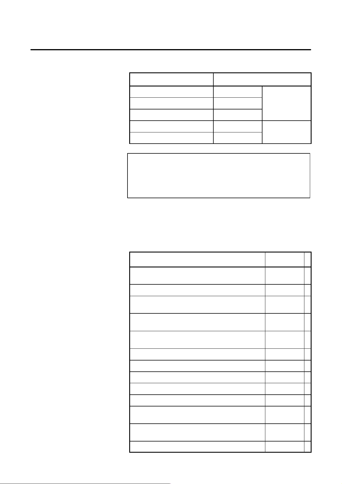
Applicable models
Related manuals of
Series 0i–B/0i Mate–B
The models covered by this manual, and their abbreviations are:
Product name Abbreviation
FANUC Series 0i–TB 0i–TB
FANUC Series 0i–MB 0i–MB
FANUC Series 0i–PB 0i–PB
FANUC Series 0i Mate–TB 0i–Mate TB
FANUC Series 0i Mate–MB 0i–Mate TB
Series 0i
Series 0i Mate
NOTE
Some function described in this manual may not be applied
to some products.
For details, refer to the DESCRIPTIONS manual
(B–63832EN)
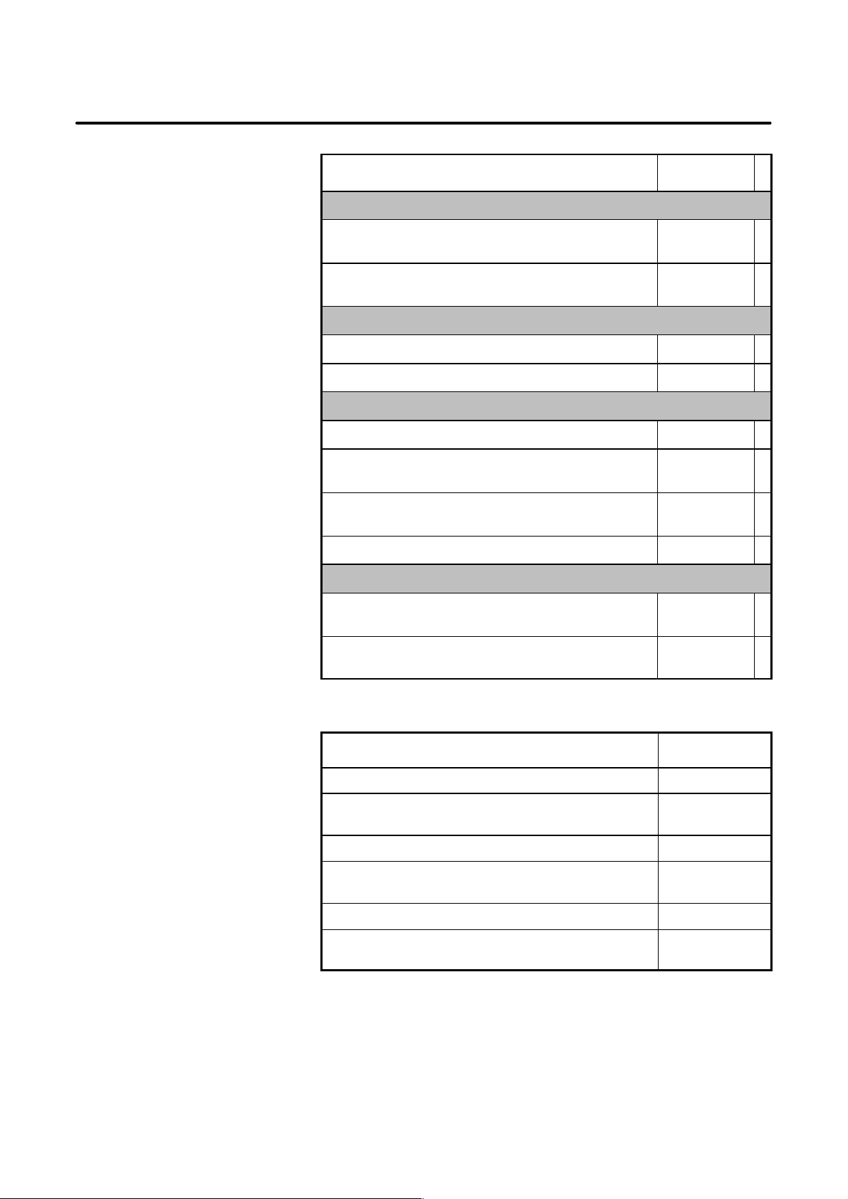
The following table lists the manuals related to Series 0i–B, Series 0i
Mate–B.
This manual is indicated by an asterisk(*).
Manual name
FANUC Series 0i–MODEL B/0i Mate–MODEL B
DESCRIPTIONS
FANUC Series 0i–PB DESCRIPTIONS B–63972EN
FANUC Series 0i–MODEL B/0i Mate–MODEL B
CONNECTION MANUAL (HARDWARE)
FANUC Series 0i–MODEL B/0i Mate–MODEL B
CONNECTION MANUAL (FUNCTION)
FANUC Series 0i–PB
CONNECTION MANUAL (FUNCTION)
FANUC Series 0i–TB OPERATOR’S MANUAL B–63834EN
FANUC Series 0i–MB OPERATOR’S MANUAL B–63844EN
FANUC Series 0i Mate–TB OPERATOR’S MANUAL B–63854EN
FANUC Series 0i Mate–MB OPERATOR’S MANUAL B–63864EN
FANUC Series 0i–PB OPERATOR’S MANUAL B–63974EN
FANUC Series 0i–MODEL B/0i Mate–MODEL B
MAINTENANCE MANUAL
Specification
number
B–63832EN
B–63833EN
B–63833EN–1
B–63973EN
B–63835EN *
FANUC Series 0i–MODEL B/0i Mate–MODEL B
P ARAMETER MANUAL
FANUC Series 0i–PB PARAMETER MANUAL B–63980EN
B–63840EN
p–2
Page 15
B–63835EN/03
PREFACE
Manual name
PROGRAMMING MANUAL
Macro Compiler/Macro Executor
PROGRAMMING MANUAL
FANUC MACRO COMPILER (For Personal Computer)
PROGRAMMING MANUAL
PMC
PMC Ladder Language PROGRAMMING MANUAL B–61863E
PMC C Language PROGRAMMING MANUA B–61863E–1
Network
PROFIBUS–DP Board OPERA T OR’S MANUAL B–62924EN
Ethernet Board/DA T A SERVER Board
OPERATOR’S MANUAL
AST Ethernet Board/FAST DATA SERVER
OPERATOR’S MANUAL
DeviceNet Board OPERA T OR’S MANUAL B–63404EN
Specification
number
B–61803E–1
B–66102E
B–63354EN
B–63644EN
Related manuals of
SERVO MOTOR ai series
OPEN CNC
FANUC OPEN CNC OPERATOR’S MANUAL
Basic Operation Package 1 (For Windows 95/NT)
FANUC OPEN CNC OPERATOR’S MANUAL
(DNC Operation Management Package)
B–62994EN
B–63214EN
The following table lists the manuals related to SER VO MOTOR αi series
Manual name
FANUC AC SER VO MOTOR αi series DESCRIPTIONS B–65262EN
FANUC AC SER VO MOTOR αi series
P ARAMETER MANUAL
FANUC AC SPINDLE MOT OR αi series DESCRIPTIONS B–65272EN
FANUC AC SPINDLE MOT OR αi series
P ARAMETER MANUAL
FANUC SER VO AMPLIFIER αi series DESCRIPTIONS B–65282EN
FANUC SER VO MOT OR αi series
MAINTENANCE MANUAL
Specification
number
B–65270EN
B–65280EN
B–65285EN
p–3
Page 16

PREFACE
B–63835EN/03
Related manuals of
SERVO MOTOR β series
The following table lists the manuals related to SER VO MOT OR β series
Manual name
FANUC SER VO MOT OR β series DESCRIPTIONS B–65232EN
FANUC SER VO MOT OR β series MAINTENANCE
MANUAL
FANUC SER VO MOT OR β series (I/O Link Option)
MAINTENANCE MANUAL
Specification
number
B–65235EN
B–65245EN
p–4
Page 17

B–63835EN/03
Table of Contents
SAFETY PRECAUTIONS s–1. . . . . . . . . . . . . . . . . . . . . . . . . . . . . . . . . . . . . . . . . . . . . . . . . .
PREFACE p–1. . . . . . . . . . . . . . . . . . . . . . . . . . . . . . . . . . . . . . . . . . . . . . . . . . . . . . . . . . . . . . . .
1. DISPLAY AND OPERATION 1. . . . . . . . . . . . . . . . . . . . . . . . . . . . . . . . . . . . . . . . . . . . .
1.1 FUNCTION KEYS AND SOFT KEYS 2. . . . . . . . . . . . . . . . . . . . . . . . . . . . . . . . . . . . . . . . . . . . . . .
1.1.1 Soft Keys 2. . . . . . . . . . . . . . . . . . . . . . . . . . . . . . . . . . . . . . . . . . . . . . . . . . . . . . . . . . . . . . . . . . . . . . .
1.2 SCREEN DISPLAYED IMMEDIATELY AFTER POWER IS TURNED ON 23. . . . . . . . . . . . . . . . .
1.2.1 Slot Status Display 23. . . . . . . . . . . . . . . . . . . . . . . . . . . . . . . . . . . . . . . . . . . . . . . . . . . . . . . . . . . . . . . .
1.2.2 Setting Module Screen 24. . . . . . . . . . . . . . . . . . . . . . . . . . . . . . . . . . . . . . . . . . . . . . . . . . . . . . . . . . . . .
1.2.3 Configuration Display of Software 24. . . . . . . . . . . . . . . . . . . . . . . . . . . . . . . . . . . . . . . . . . . . . . . . . . . .
1.3 SYSTEM CONFIGURATION SCREEN 25. . . . . . . . . . . . . . . . . . . . . . . . . . . . . . . . . . . . . . . . . . . . . .
1.3.1 Display Method 25. . . . . . . . . . . . . . . . . . . . . . . . . . . . . . . . . . . . . . . . . . . . . . . . . . . . . . . . . . . . . . . . . .
1.3.2 Configuration of PCBs 25. . . . . . . . . . . . . . . . . . . . . . . . . . . . . . . . . . . . . . . . . . . . . . . . . . . . . . . . . . . . .
1.3.3 Software Configuration Screen 26. . . . . . . . . . . . . . . . . . . . . . . . . . . . . . . . . . . . . . . . . . . . . . . . . . . . . . .
1.3.4 Module Configuration Screen 26. . . . . . . . . . . . . . . . . . . . . . . . . . . . . . . . . . . . . . . . . . . . . . . . . . . . . . . .
1.3.5 ID Information Screen (αi Servo Information Screen/αi Spindle Information Screen) 27. . . . . . . . . . . . .
1.4 ALARM HISTORY SCREEN 28. . . . . . . . . . . . . . . . . . . . . . . . . . . . . . . . . . . . . . . . . . . . . . . . . . . . . .
1.4.1 Alarm History Screen 28. . . . . . . . . . . . . . . . . . . . . . . . . . . . . . . . . . . . . . . . . . . . . . . . . . . . . . . . . . . . . .
1.4.1.1 General 28. . . . . . . . . . . . . . . . . . . . . . . . . . . . . . . . . . . . . . . . . . . . . . . . . . . . . . . . . . . . . . . . . . .
1.4.1.2 Screen display 28. . . . . . . . . . . . . . . . . . . . . . . . . . . . . . . . . . . . . . . . . . . . . . . . . . . . . . . . . . . . .
1.4.1.3 Clearing alarm history 28. . . . . . . . . . . . . . . . . . . . . . . . . . . . . . . . . . . . . . . . . . . . . . . . . . . . . . .
1.4.1.4 Alarm display 28. . . . . . . . . . . . . . . . . . . . . . . . . . . . . . . . . . . . . . . . . . . . . . . . . . . . . . . . . . . . . .
1.4.2 System Alarm History 29. . . . . . . . . . . . . . . . . . . . . . . . . . . . . . . . . . . . . . . . . . . . . . . . . . . . . . . . . . . . .
1.4.2.1 General 29. . . . . . . . . . . . . . . . . . . . . . . . . . . . . . . . . . . . . . . . . . . . . . . . . . . . . . . . . . . . . . . . . . .
1.4.2.2 System alarm history screen (history list screen) 29. . . . . . . . . . . . . . . . . . . . . . . . . . . . . . . . . . . .
1.4.2.3 System alarm history screen (detail screen) 31. . . . . . . . . . . . . . . . . . . . . . . . . . . . . . . . . . . . . . .
1.4.2.4 Parameter 34. . . . . . . . . . . . . . . . . . . . . . . . . . . . . . . . . . . . . . . . . . . . . . . . . . . . . . . . . . . . . . . . .
1.5 EXTERNAL OPERATOR MESSAGES RECORD 35. . . . . . . . . . . . . . . . . . . . . . . . . . . . . . . . . . . . . .
1.5.1 Screen Display 35. . . . . . . . . . . . . . . . . . . . . . . . . . . . . . . . . . . . . . . . . . . . . . . . . . . . . . . . . . . . . . . . . . .
1.5.2 Deletion of External Operator Messages Record 35. . . . . . . . . . . . . . . . . . . . . . . . . . . . . . . . . . . . . . . . . .
1.5.3 Parameter 36. . . . . . . . . . . . . . . . . . . . . . . . . . . . . . . . . . . . . . . . . . . . . . . . . . . . . . . . . . . . . . . . . . . . . . .
1.5.4 Notes 36. . . . . . . . . . . . . . . . . . . . . . . . . . . . . . . . . . . . . . . . . . . . . . . . . . . . . . . . . . . . . . . . . . . . . . . . . .
1.6 OPERATION HISTORY 37. . . . . . . . . . . . . . . . . . . . . . . . . . . . . . . . . . . . . . . . . . . . . . . . . . . . . . . . . . .
1.6.1 Parameter Setting 37. . . . . . . . . . . . . . . . . . . . . . . . . . . . . . . . . . . . . . . . . . . . . . . . . . . . . . . . . . . . . . . . .
1.6.2 Screen Display 42. . . . . . . . . . . . . . . . . . . . . . . . . . . . . . . . . . . . . . . . . . . . . . . . . . . . . . . . . . . . . . . . . . .
1.6.3 Setting the Input Signal or Output Signal to be Recorded in the Operation History 46. . . . . . . . . . . . . . .
1.6.4 Inputting and Outputting the Operation History Data 50. . . . . . . . . . . . . . . . . . . . . . . . . . . . . . . . . . . . . .
1.6.5 Notes 55. . . . . . . . . . . . . . . . . . . . . . . . . . . . . . . . . . . . . . . . . . . . . . . . . . . . . . . . . . . . . . . . . . . . . . . . . .
1.7 HELP FUNCTION 56. . . . . . . . . . . . . . . . . . . . . . . . . . . . . . . . . . . . . . . . . . . . . . . . . . . . . . . . . . . . . . .
1.7.1 General 56. . . . . . . . . . . . . . . . . . . . . . . . . . . . . . . . . . . . . . . . . . . . . . . . . . . . . . . . . . . . . . . . . . . . . . . . .
1.7.2 Display Method 56. . . . . . . . . . . . . . . . . . . . . . . . . . . . . . . . . . . . . . . . . . . . . . . . . . . . . . . . . . . . . . . . . .
1.8 DISPLAYING DIAGNOSTIC PAGE 59. . . . . . . . . . . . . . . . . . . . . . . . . . . . . . . . . . . . . . . . . . . . . . . . .
1.8.1 Displaying Diagnostic Page 59. . . . . . . . . . . . . . . . . . . . . . . . . . . . . . . . . . . . . . . . . . . . . . . . . . . . . . . . .
1.8.2 Contents Displayed 59. . . . . . . . . . . . . . . . . . . . . . . . . . . . . . . . . . . . . . . . . . . . . . . . . . . . . . . . . . . . . . . .
1.9 CNC STATE DISPLAY 82. . . . . . . . . . . . . . . . . . . . . . . . . . . . . . . . . . . . . . . . . . . . . . . . . . . . . . . . . . .
1.10 WAVEFORM DIAGNOSTIC FUNCTION 84. . . . . . . . . . . . . . . . . . . . . . . . . . . . . . . . . . . . . . . . . . . .
1.10.1 Setting Parameters 84. . . . . . . . . . . . . . . . . . . . . . . . . . . . . . . . . . . . . . . . . . . . . . . . . . . . . . . . . . . . . . . .
1.10.2 W aveform Diagnostic Parameter Screen 85. . . . . . . . . . . . . . . . . . . . . . . . . . . . . . . . . . . . . . . . . . . . . . . .
1.10.3 Graphic of W ave Diagnosis Data 88. . . . . . . . . . . . . . . . . . . . . . . . . . . . . . . . . . . . . . . . . . . . . . . . . . . . .
1.10.4 Data Sampling for Storage T ype W aveform Diagnosis 90. . . . . . . . . . . . . . . . . . . . . . . . . . . . . . . . . . . . .
c–1
Page 18

Table of Contents
1.10.5 Outputting Waveform Diagnosis Data (Storage T ype) 92. . . . . . . . . . . . . . . . . . . . . . . . . . . . . . . . . . . . .
1.10.6 Notes 95. . . . . . . . . . . . . . . . . . . . . . . . . . . . . . . . . . . . . . . . . . . . . . . . . . . . . . . . . . . . . . . . . . . . . . . . . .
B–63835EN/03
1.11 OPERATING MONITOR 96. . . . . . . . . . . . . . . . . . . . . . . . . . . . . . . . . . . . . . . . . . . . . . . . . . . . . . . . . .
1.11.1 Display Method 96. . . . . . . . . . . . . . . . . . . . . . . . . . . . . . . . . . . . . . . . . . . . . . . . . . . . . . . . . . . . . . . . . .
1.11.2 Parameters 97. . . . . . . . . . . . . . . . . . . . . . . . . . . . . . . . . . . . . . . . . . . . . . . . . . . . . . . . . . . . . . . . . . . . . .
1.12 LIST OF OPERATIONS 98. . . . . . . . . . . . . . . . . . . . . . . . . . . . . . . . . . . . . . . . . . . . . . . . . . . . . . . . . . .
1.13 WARNING SCREEN DISPLAYED WHEN AN OPTION IS CHANGED 108. . . . . . . . . . . . . . . . . . .
1.14 WARNING SCREEN DISPLAYED WHEN SYSTEM SOFTWARE IS REPLACED
(SYSTEM LABEL CHECK ERROR) 110. . . . . . . . . . . . . . . . . . . . . . . . . . . . . . . . . . . . . . . . . . . . . . . .
1.15 MAINTENANCE INFORMATION SCREEN 111. . . . . . . . . . . . . . . . . . . . . . . . . . . . . . . . . . . . . . . . . .
1.15.1 Screen Display and Operation 111. . . . . . . . . . . . . . . . . . . . . . . . . . . . . . . . . . . . . . . . . . . . . . . . . . . . . . . .
1.15.2 Maintenance Information Input/Output 114. . . . . . . . . . . . . . . . . . . . . . . . . . . . . . . . . . . . . . . . . . . . . . . .
1.16 COLOR SETTING SCREEN (10.4″ COLOR LCD) 115. . . . . . . . . . . . . . . . . . . . . . . . . . . . . . . . . . . . .
1.16.1 Screen Display 115. . . . . . . . . . . . . . . . . . . . . . . . . . . . . . . . . . . . . . . . . . . . . . . . . . . . . . . . . . . . . . . . . . .
1.16.2 Color Setting 115. . . . . . . . . . . . . . . . . . . . . . . . . . . . . . . . . . . . . . . . . . . . . . . . . . . . . . . . . . . . . . . . . . . .
1.16.3 Parameters 117. . . . . . . . . . . . . . . . . . . . . . . . . . . . . . . . . . . . . . . . . . . . . . . . . . . . . . . . . . . . . . . . . . . . . .
1.16.4 Notes 118. . . . . . . . . . . . . . . . . . . . . . . . . . . . . . . . . . . . . . . . . . . . . . . . . . . . . . . . . . . . . . . . . . . . . . . . . .
1.17 CONTRAST ADJUSTMENT 119. . . . . . . . . . . . . . . . . . . . . . . . . . . . . . . . . . . . . . . . . . . . . . . . . . . . . . .
1.18 POWER MATE CNC MANAGER 120. . . . . . . . . . . . . . . . . . . . . . . . . . . . . . . . . . . . . . . . . . . . . . . . . .
1.18.1 Parameter 120. . . . . . . . . . . . . . . . . . . . . . . . . . . . . . . . . . . . . . . . . . . . . . . . . . . . . . . . . . . . . . . . . . . . . . .
1.18.2 Screen Display 121. . . . . . . . . . . . . . . . . . . . . . . . . . . . . . . . . . . . . . . . . . . . . . . . . . . . . . . . . . . . . . . . . . .
1.18.3 Parameter Input/Output 127. . . . . . . . . . . . . . . . . . . . . . . . . . . . . . . . . . . . . . . . . . . . . . . . . . . . . . . . . . . .
1.18.4 Notes 129. . . . . . . . . . . . . . . . . . . . . . . . . . . . . . . . . . . . . . . . . . . . . . . . . . . . . . . . . . . . . . . . . . . . . . . . . .
1.19 PERIODIC MAINTENANCE SCREENS 130. . . . . . . . . . . . . . . . . . . . . . . . . . . . . . . . . . . . . . . . . . . . .
1.19.1 Overview 130. . . . . . . . . . . . . . . . . . . . . . . . . . . . . . . . . . . . . . . . . . . . . . . . . . . . . . . . . . . . . . . . . . . . . . .
1.19.2 Screen Display and Setting 130. . . . . . . . . . . . . . . . . . . . . . . . . . . . . . . . . . . . . . . . . . . . . . . . . . . . . . . . . .
1.19.3 Status Screen Display and Setting 131. . . . . . . . . . . . . . . . . . . . . . . . . . . . . . . . . . . . . . . . . . . . . . . . . . . . .
1.19.4 Setting Screen Display and Setting 136. . . . . . . . . . . . . . . . . . . . . . . . . . . . . . . . . . . . . . . . . . . . . . . . . . . .
1.19.5 Registered Data Input/Output 138. . . . . . . . . . . . . . . . . . . . . . . . . . . . . . . . . . . . . . . . . . . . . . . . . . . . . . . .
1.19.6 F ANUC T wo–Byte Character Code T able 140. . . . . . . . . . . . . . . . . . . . . . . . . . . . . . . . . . . . . . . . . . . . . .
2. HARDWARE 146. . . . . . . . . . . . . . . . . . . . . . . . . . . . . . . . . . . . . . . . . . . . . . . . . . . . . . . . . .
2.1 HARDWARE CONFIGURATION 147. . . . . . . . . . . . . . . . . . . . . . . . . . . . . . . . . . . . . . . . . . . . . . . . . . .
2.2 HARDWARE OVERVIEW 148. . . . . . . . . . . . . . . . . . . . . . . . . . . . . . . . . . . . . . . . . . . . . . . . . . . . . . . .
2.3 TOTAL CONNECTION DIAGRAMS 149. . . . . . . . . . . . . . . . . . . . . . . . . . . . . . . . . . . . . . . . . . . . . . . .
2.4 CONNECTOR AND CARD CONFIGURATIONS OF PRINTED CIRCUIT BOARDS 152. . . . . . . . .
2.4.1 Main CPU Board 152. . . . . . . . . . . . . . . . . . . . . . . . . . . . . . . . . . . . . . . . . . . . . . . . . . . . . . . . . . . . . . . . .
2.4.2 Built–in I/O Board 158. . . . . . . . . . . . . . . . . . . . . . . . . . . . . . . . . . . . . . . . . . . . . . . . . . . . . . . . . . . . . . . .
2.4.3 Serial Communication Board 161. . . . . . . . . . . . . . . . . . . . . . . . . . . . . . . . . . . . . . . . . . . . . . . . . . . . . . . .
2.4.4 HSSB Interface Board 162. . . . . . . . . . . . . . . . . . . . . . . . . . . . . . . . . . . . . . . . . . . . . . . . . . . . . . . . . . . . .
2.4.5 Fast Ethernet Board 166. . . . . . . . . . . . . . . . . . . . . . . . . . . . . . . . . . . . . . . . . . . . . . . . . . . . . . . . . . . . . . .
2.4.6 DeviceNet Board 168. . . . . . . . . . . . . . . . . . . . . . . . . . . . . . . . . . . . . . . . . . . . . . . . . . . . . . . . . . . . . . . . .
2.4.7 PROFIBUS Master Board 169. . . . . . . . . . . . . . . . . . . . . . . . . . . . . . . . . . . . . . . . . . . . . . . . . . . . . . . . . .
2.4.8 PROFIBUS Slave Board 170. . . . . . . . . . . . . . . . . . . . . . . . . . . . . . . . . . . . . . . . . . . . . . . . . . . . . . . . . . .
2.4.9 FL–net Board 171. . . . . . . . . . . . . . . . . . . . . . . . . . . . . . . . . . . . . . . . . . . . . . . . . . . . . . . . . . . . . . . . . . . .
2.4.10 Main CPU Board of CNC Display Unit with PC Functions and P ANEL i 172. . . . . . . . . . . . . . . . . . . . . .
2.5 UNITS AND PRINTED CIRCUIT BOARDS 175. . . . . . . . . . . . . . . . . . . . . . . . . . . . . . . . . . . . . . . . . .
2.5.1 Basic Units 175. . . . . . . . . . . . . . . . . . . . . . . . . . . . . . . . . . . . . . . . . . . . . . . . . . . . . . . . . . . . . . . . . . . . . .
2.5.2 Printed Circuit Boards of Control Unit 175. . . . . . . . . . . . . . . . . . . . . . . . . . . . . . . . . . . . . . . . . . . . . . . . .
2.5.3 LCD/MDI Unit 178. . . . . . . . . . . . . . . . . . . . . . . . . . . . . . . . . . . . . . . . . . . . . . . . . . . . . . . . . . . . . . . . . . .
2.5.4 Other Units 180. . . . . . . . . . . . . . . . . . . . . . . . . . . . . . . . . . . . . . . . . . . . . . . . . . . . . . . . . . . . . . . . . . . . . .
2.5.5 CNC Display Unit with PC Functions and P ANEL i 181. . . . . . . . . . . . . . . . . . . . . . . . . . . . . . . . . . . . . .
c–2
Page 19

B–63835EN/03
2.6 MOUNTING AND REMOVING AN OPTION BOARD 184. . . . . . . . . . . . . . . . . . . . . . . . . . . . . . . . .
2.7 MOUNTING AND DEMOUNTING CARD PCBS 189. . . . . . . . . . . . . . . . . . . . . . . . . . . . . . . . . . . . . .
2.8 MOUNTING AND DEMOUNTING DIMM MODULES 192. . . . . . . . . . . . . . . . . . . . . . . . . . . . . . . . .
2.9 MOUNTING AND REMOVING THE BACK PANEL 194. . . . . . . . . . . . . . . . . . . . . . . . . . . . . . . . . . .
2.10 REPLACING THE FUSE OF THE CONTROL UNIT 196. . . . . . . . . . . . . . . . . . . . . . . . . . . . . . . . . . .
2.11 REPLACING THE BATTERY 197. . . . . . . . . . . . . . . . . . . . . . . . . . . . . . . . . . . . . . . . . . . . . . . . . . . . . .
2.12 REPLACING A FAN UNIT 204. . . . . . . . . . . . . . . . . . . . . . . . . . . . . . . . . . . . . . . . . . . . . . . . . . . . . . . .
2.13 REPLACING THE FUSE OF THE LCD UNIT 205. . . . . . . . . . . . . . . . . . . . . . . . . . . . . . . . . . . . . . . .
2.14 REPLACING THE LCD BACKLIGHT 206. . . . . . . . . . . . . . . . . . . . . . . . . . . . . . . . . . . . . . . . . . . . . .
2.15 HEAT LOSS OF EACH UNIT 211. . . . . . . . . . . . . . . . . . . . . . . . . . . . . . . . . . . . . . . . . . . . . . . . . . . . . .
2.16 DISTRIBUTED I/O SETTING (SERIES 0i–B ONLY) 212. . . . . . . . . . . . . . . . . . . . . . . . . . . . . . . . . . .
2.17 REPLACING FUSES ON VARIOUS UNITS 215. . . . . . . . . . . . . . . . . . . . . . . . . . . . . . . . . . . . . . . . . .
2.18 ENVIRONMENTAL REQUIREMENTS OUTSIDE THE CONTROL UNIT 218. . . . . . . . . . . . . . . . .
2.19 ACTION AGAINST NOISE 219. . . . . . . . . . . . . . . . . . . . . . . . . . . . . . . . . . . . . . . . . . . . . . . . . . . . . . .
2.20 REPLACING THE MAINTENANCE PARTS OF CNC DISPLAY UNIT FOR PC FUNCTIONS
Table of Contents
2.6.1 Mounting and Removing the Main CPU Board and a Full–Size Option Board 184. . . . . . . . . . . . . . . . . .
2.6.1.1 Removing the board 184. . . . . . . . . . . . . . . . . . . . . . . . . . . . . . . . . . . . . . . . . . . . . . . . . . . . . . . . .
2.6.1.2 Mounting the board 185. . . . . . . . . . . . . . . . . . . . . . . . . . . . . . . . . . . . . . . . . . . . . . . . . . . . . . . . .
2.6.2 Mounting and Removing a Mini–Slot Option Board (Except DeviceNet Board) 186. . . . . . . . . . . . . . . . .
2.6.2.1 Removing the board 186. . . . . . . . . . . . . . . . . . . . . . . . . . . . . . . . . . . . . . . . . . . . . . . . . . . . . . . . .
2.6.2.2 Mounting the board 186. . . . . . . . . . . . . . . . . . . . . . . . . . . . . . . . . . . . . . . . . . . . . . . . . . . . . . . . .
2.6.3 Mounting and Removing the DeviceNet Board 187. . . . . . . . . . . . . . . . . . . . . . . . . . . . . . . . . . . . . . . . . .
2.6.3.1 Removing the board 187. . . . . . . . . . . . . . . . . . . . . . . . . . . . . . . . . . . . . . . . . . . . . . . . . . . . . . . . .
2.6.3.2 Mounting the board 187. . . . . . . . . . . . . . . . . . . . . . . . . . . . . . . . . . . . . . . . . . . . . . . . . . . . . . . . .
2.7.1 Demounting a Card PCB 190. . . . . . . . . . . . . . . . . . . . . . . . . . . . . . . . . . . . . . . . . . . . . . . . . . . . . . . . . . .
2.7.2 Mounting a Card PCB 191. . . . . . . . . . . . . . . . . . . . . . . . . . . . . . . . . . . . . . . . . . . . . . . . . . . . . . . . . . . . .
2.8.1 Demounting a DIMM Module 193. . . . . . . . . . . . . . . . . . . . . . . . . . . . . . . . . . . . . . . . . . . . . . . . . . . . . . .
2.8.2 Mounting a DIMM Module 193. . . . . . . . . . . . . . . . . . . . . . . . . . . . . . . . . . . . . . . . . . . . . . . . . . . . . . . . .
2.9.1 Removing the Panel 194. . . . . . . . . . . . . . . . . . . . . . . . . . . . . . . . . . . . . . . . . . . . . . . . . . . . . . . . . . . . . . .
2.9.2 Mounting the Back Panel 194. . . . . . . . . . . . . . . . . . . . . . . . . . . . . . . . . . . . . . . . . . . . . . . . . . . . . . . . . . .
2.11.1 Battery for Memory Backup (3VDC) 197. . . . . . . . . . . . . . . . . . . . . . . . . . . . . . . . . . . . . . . . . . . . . . . . . .
2.11.2 Batteries for CNC Display Unit with PC Functions (3VDC) 201. . . . . . . . . . . . . . . . . . . . . . . . . . . . . . . .
2.11.3 Battery for Separate Absolute Pulse Coders (6VDC) 202. . . . . . . . . . . . . . . . . . . . . . . . . . . . . . . . . . . . . .
2.11.4 Battery for Absolute Pulse Coder Built into the Motor (6VDC) 203. . . . . . . . . . . . . . . . . . . . . . . . . . . . . .
2.19.1 Separating Signal Lines 219. . . . . . . . . . . . . . . . . . . . . . . . . . . . . . . . . . . . . . . . . . . . . . . . . . . . . . . . . . . .
2.19.2 Ground 221. . . . . . . . . . . . . . . . . . . . . . . . . . . . . . . . . . . . . . . . . . . . . . . . . . . . . . . . . . . . . . . . . . . . . . . . .
2.19.3 Connecting the Signal Ground (SG) of the Control Unit 222. . . . . . . . . . . . . . . . . . . . . . . . . . . . . . . . . . .
2.19.4 Noise Suppressor 226. . . . . . . . . . . . . . . . . . . . . . . . . . . . . . . . . . . . . . . . . . . . . . . . . . . . . . . . . . . . . . . . .
2.19.5 Cable Clamp and Shield Processing 227. . . . . . . . . . . . . . . . . . . . . . . . . . . . . . . . . . . . . . . . . . . . . . . . . . .
AND PANEL i 230. . . . . . . . . . . . . . . . . . . . . . . . . . . . . . . . . . . . . . . . . . . . . . . . . . . . . . . . . . . . . . . . . .
2.20.1 Replacing the Battery 230. . . . . . . . . . . . . . . . . . . . . . . . . . . . . . . . . . . . . . . . . . . . . . . . . . . . . . . . . . . . . .
2.20.2 Replacing the Fuse 232. . . . . . . . . . . . . . . . . . . . . . . . . . . . . . . . . . . . . . . . . . . . . . . . . . . . . . . . . . . . . . . .
2.20.3 Replacing the Fan 233. . . . . . . . . . . . . . . . . . . . . . . . . . . . . . . . . . . . . . . . . . . . . . . . . . . . . . . . . . . . . . . . .
2.20.4 Replacing the LCD Back–Light 236. . . . . . . . . . . . . . . . . . . . . . . . . . . . . . . . . . . . . . . . . . . . . . . . . . . . . .
2.20.5 Replacing the T ouch Panel Protection Sheet 237. . . . . . . . . . . . . . . . . . . . . . . . . . . . . . . . . . . . . . . . . . . . .
3. INPUT AND OUTPUT OF DATA 242. . . . . . . . . . . . . . . . . . . . . . . . . . . . . . . . . . . . . . . . .
3.1 SETTING PARAMETERS FOR INPUT/OUTPUT 243. . . . . . . . . . . . . . . . . . . . . . . . . . . . . . . . . . . . . .
3.2 INPUTTING/OUTPUTTING DATA 245. . . . . . . . . . . . . . . . . . . . . . . . . . . . . . . . . . . . . . . . . . . . . . . . .
3.2.1 Confirming the Parameters Required for Data Output 245. . . . . . . . . . . . . . . . . . . . . . . . . . . . . . . . . . . . .
c–3
Page 20

Table of Contents
3.2.2 Outputting CNC Parameters 246. . . . . . . . . . . . . . . . . . . . . . . . . . . . . . . . . . . . . . . . . . . . . . . . . . . . . . . . .
3.2.3 Outputting PMC Parameters 247. . . . . . . . . . . . . . . . . . . . . . . . . . . . . . . . . . . . . . . . . . . . . . . . . . . . . . . . .
3.2.4 Outputting Pitch Error Compensation Amount 247. . . . . . . . . . . . . . . . . . . . . . . . . . . . . . . . . . . . . . . . . . .
3.2.5 Outputting Custom Macro V ariable Values 248. . . . . . . . . . . . . . . . . . . . . . . . . . . . . . . . . . . . . . . . . . . . . .
3.2.6 Outputting Tool Compensation Amount 248. . . . . . . . . . . . . . . . . . . . . . . . . . . . . . . . . . . . . . . . . . . . . . . .
3.2.7 Outputting Part Program 248. . . . . . . . . . . . . . . . . . . . . . . . . . . . . . . . . . . . . . . . . . . . . . . . . . . . . . . . . . . .
3.2.8 Inputting CNC Parameters 249. . . . . . . . . . . . . . . . . . . . . . . . . . . . . . . . . . . . . . . . . . . . . . . . . . . . . . . . . .
3.2.9 Inputting PMC Parameters 250. . . . . . . . . . . . . . . . . . . . . . . . . . . . . . . . . . . . . . . . . . . . . . . . . . . . . . . . . .
3.2.10 Inputting Pitch Error Compensation Amount 251. . . . . . . . . . . . . . . . . . . . . . . . . . . . . . . . . . . . . . . . . . . .
3.2.11 Inputting Custom Macro V ariable Values 251. . . . . . . . . . . . . . . . . . . . . . . . . . . . . . . . . . . . . . . . . . . . . . .
3.2.12 Inputting Tool Compensation Amount 252. . . . . . . . . . . . . . . . . . . . . . . . . . . . . . . . . . . . . . . . . . . . . . . . .
3.2.13 Inputting Part Programs 252. . . . . . . . . . . . . . . . . . . . . . . . . . . . . . . . . . . . . . . . . . . . . . . . . . . . . . . . . . . .
B–63835EN/03
3.3 DATA INPUT/OUTPUT ON THE ALL IO SCREEN 254. . . . . . . . . . . . . . . . . . . . . . . . . . . . . . . . . . . .
3.3.1 Setting Input/Output–Related Parameters 255. . . . . . . . . . . . . . . . . . . . . . . . . . . . . . . . . . . . . . . . . . . . . . .
3.3.2 Inputting and Outputting Programs 257. . . . . . . . . . . . . . . . . . . . . . . . . . . . . . . . . . . . . . . . . . . . . . . . . . .
3.3.3 Inputting and Outputting Parameters 261. . . . . . . . . . . . . . . . . . . . . . . . . . . . . . . . . . . . . . . . . . . . . . . . . .
3.3.4 Inputting and Outputting Offset Data 262. . . . . . . . . . . . . . . . . . . . . . . . . . . . . . . . . . . . . . . . . . . . . . . . . .
3.3.5 Outputting Custom Macro Common Variables 263. . . . . . . . . . . . . . . . . . . . . . . . . . . . . . . . . . . . . . . . . . .
3.3.6 Inputting and Outputting Floppy Files 264. . . . . . . . . . . . . . . . . . . . . . . . . . . . . . . . . . . . . . . . . . . . . . . . .
3.4 DATA INPUT/OUTPUT USING A MEMORY CARD 269. . . . . . . . . . . . . . . . . . . . . . . . . . . . . . . . . . .
4. INTERFACE BETWEEN CNC AND PMC 279. . . . . . . . . . . . . . . . . . . . . . . . . . . . . . . . . .
4.1 GENERAL OF INTERFACE 280. . . . . . . . . . . . . . . . . . . . . . . . . . . . . . . . . . . . . . . . . . . . . . . . . . . . . . .
4.2 SPECIFICATION OF PMC 281. . . . . . . . . . . . . . . . . . . . . . . . . . . . . . . . . . . . . . . . . . . . . . . . . . . . . . . .
4.2.1 Specification 281. . . . . . . . . . . . . . . . . . . . . . . . . . . . . . . . . . . . . . . . . . . . . . . . . . . . . . . . . . . . . . . . . . . . .
4.2.2 Address 282. . . . . . . . . . . . . . . . . . . . . . . . . . . . . . . . . . . . . . . . . . . . . . . . . . . . . . . . . . . . . . . . . . . . . . . . .
4.2.3 System Reserve Area of Internal Relay 283. . . . . . . . . . . . . . . . . . . . . . . . . . . . . . . . . . . . . . . . . . . . . . . . .
4.2.4 Execution Period of PMC 286. . . . . . . . . . . . . . . . . . . . . . . . . . . . . . . . . . . . . . . . . . . . . . . . . . . . . . . . . . .
4.2.5 I/O Module Assignment Name List 288. . . . . . . . . . . . . . . . . . . . . . . . . . . . . . . . . . . . . . . . . . . . . . . . . . .
4.3 PMC SCREEN (PMC–SA1) 291. . . . . . . . . . . . . . . . . . . . . . . . . . . . . . . . . . . . . . . . . . . . . . . . . . . . . . . .
4.3.1 PMC Menu Selection Procedure Using Soft Keys 291. . . . . . . . . . . . . . . . . . . . . . . . . . . . . . . . . . . . . . . .
4.3.2 Dynamic Display of Sequence Program 292. . . . . . . . . . . . . . . . . . . . . . . . . . . . . . . . . . . . . . . . . . . . . . . .
4.3.3 Display of PMC Diagnosis Screen 297. . . . . . . . . . . . . . . . . . . . . . . . . . . . . . . . . . . . . . . . . . . . . . . . . . . .
4.3.3.1 Title screen (TITLE) 297. . . . . . . . . . . . . . . . . . . . . . . . . . . . . . . . . . . . . . . . . . . . . . . . . . . . . . . . .
4.3.3.2 Status screen (STA TUS) 298. . . . . . . . . . . . . . . . . . . . . . . . . . . . . . . . . . . . . . . . . . . . . . . . . . . . . .
4.3.3.3 Alarm screen (ALARM) 299. . . . . . . . . . . . . . . . . . . . . . . . . . . . . . . . . . . . . . . . . . . . . . . . . . . . . .
4.3.3.4 Trace screen (TRACE) 299. . . . . . . . . . . . . . . . . . . . . . . . . . . . . . . . . . . . . . . . . . . . . . . . . . . . . . .
4.3.4 PMC Parameter 301. . . . . . . . . . . . . . . . . . . . . . . . . . . . . . . . . . . . . . . . . . . . . . . . . . . . . . . . . . . . . . . . . .
4.3.4.1 Input of PMC parameter from MDI 301. . . . . . . . . . . . . . . . . . . . . . . . . . . . . . . . . . . . . . . . . . . . .
4.3.4.2 Timer screen (TIMER) 301. . . . . . . . . . . . . . . . . . . . . . . . . . . . . . . . . . . . . . . . . . . . . . . . . . . . . . .
4.3.4.3 Counter screen (COUNTER) 302. . . . . . . . . . . . . . . . . . . . . . . . . . . . . . . . . . . . . . . . . . . . . . . . . .
4.3.4.4 Keep relay screen (KEEPRL) 302. . . . . . . . . . . . . . . . . . . . . . . . . . . . . . . . . . . . . . . . . . . . . . . . . .
4.3.4.5 Data table screen (DAT A) 305. . . . . . . . . . . . . . . . . . . . . . . . . . . . . . . . . . . . . . . . . . . . . . . . . . . . .
4.3.4.6 Setting screen 306. . . . . . . . . . . . . . . . . . . . . . . . . . . . . . . . . . . . . . . . . . . . . . . . . . . . . . . . . . . . . .
4.3.5 Input/Output of PMC Data 307. . . . . . . . . . . . . . . . . . . . . . . . . . . . . . . . . . . . . . . . . . . . . . . . . . . . . . . . . .
4.3.5.1 Start of the built-in type PMC programmer 307. . . . . . . . . . . . . . . . . . . . . . . . . . . . . . . . . . . . . . .
4.3.5.2 Input/output method 307. . . . . . . . . . . . . . . . . . . . . . . . . . . . . . . . . . . . . . . . . . . . . . . . . . . . . . . . .
4.3.5.3 Copy function (COPY) 308. . . . . . . . . . . . . . . . . . . . . . . . . . . . . . . . . . . . . . . . . . . . . . . . . . . . . .
4.3.6 System Parameters 309. . . . . . . . . . . . . . . . . . . . . . . . . . . . . . . . . . . . . . . . . . . . . . . . . . . . . . . . . . . . . . . .
4.3.7 Online Monitor Setting Screen 310. . . . . . . . . . . . . . . . . . . . . . . . . . . . . . . . . . . . . . . . . . . . . . . . . . . . . . .
4.4 PMC SCREEN (PMC–SB7) 313. . . . . . . . . . . . . . . . . . . . . . . . . . . . . . . . . . . . . . . . . . . . . . . . . . . . . . . .
4.4.1 PMC Menu Selection Procedure Using Soft Keys 313. . . . . . . . . . . . . . . . . . . . . . . . . . . . . . . . . . . . . . . .
c–4
Page 21

B–63835EN/03
4.5 LIST OF SIGNALS BY EACH MODE 345. . . . . . . . . . . . . . . . . . . . . . . . . . . . . . . . . . . . . . . . . . . . . . .
4.6 LIST OF INPUT/OUTPUT SIGNALS 347. . . . . . . . . . . . . . . . . . . . . . . . . . . . . . . . . . . . . . . . . . . . . . . .
4.7 LIST OF ADDRESSES 362. . . . . . . . . . . . . . . . . . . . . . . . . . . . . . . . . . . . . . . . . . . . . . . . . . . . . . . . . . .
Table of Contents
4.4.2 Dynamic Display of Sequence Programs 314. . . . . . . . . . . . . . . . . . . . . . . . . . . . . . . . . . . . . . . . . . . . . . .
4.4.2.1 Ladder diagram display screen 315. . . . . . . . . . . . . . . . . . . . . . . . . . . . . . . . . . . . . . . . . . . . . . . . .
4.4.2.2 Selection monitor screen 317. . . . . . . . . . . . . . . . . . . . . . . . . . . . . . . . . . . . . . . . . . . . . . . . . . . . .
4.4.2.3 Ladder diagram editing screen 318. . . . . . . . . . . . . . . . . . . . . . . . . . . . . . . . . . . . . . . . . . . . . . . . .
4.4.2.4 Net editing screen 320. . . . . . . . . . . . . . . . . . . . . . . . . . . . . . . . . . . . . . . . . . . . . . . . . . . . . . . . . . .
4.4.3 Display of the PMC Diagnosis Screen 323. . . . . . . . . . . . . . . . . . . . . . . . . . . . . . . . . . . . . . . . . . . . . . . . .
4.4.3.1 Title screen 323. . . . . . . . . . . . . . . . . . . . . . . . . . . . . . . . . . . . . . . . . . . . . . . . . . . . . . . . . . . . . . . .
4.4.3.2 Status screen 324. . . . . . . . . . . . . . . . . . . . . . . . . . . . . . . . . . . . . . . . . . . . . . . . . . . . . . . . . . . . . . .
4.4.3.3 Alarm screen 324. . . . . . . . . . . . . . . . . . . . . . . . . . . . . . . . . . . . . . . . . . . . . . . . . . . . . . . . . . . . . .
4.4.3.4 Trace function 325. . . . . . . . . . . . . . . . . . . . . . . . . . . . . . . . . . . . . . . . . . . . . . . . . . . . . . . . . . . . .
4.4.3.5 I/O Link connection check screen 329. . . . . . . . . . . . . . . . . . . . . . . . . . . . . . . . . . . . . . . . . . . . . .
4.4.4 PMC Parameters 329. . . . . . . . . . . . . . . . . . . . . . . . . . . . . . . . . . . . . . . . . . . . . . . . . . . . . . . . . . . . . . . . . .
4.4.4.1 Parameter input/output method 329. . . . . . . . . . . . . . . . . . . . . . . . . . . . . . . . . . . . . . . . . . . . . . . .
4.4.4.2 TIMER screen 330. . . . . . . . . . . . . . . . . . . . . . . . . . . . . . . . . . . . . . . . . . . . . . . . . . . . . . . . . . . . .
4.4.4.3 COUNTER screen 331. . . . . . . . . . . . . . . . . . . . . . . . . . . . . . . . . . . . . . . . . . . . . . . . . . . . . . . . . .
4.4.4.4 KEEP RELAY screen 332. . . . . . . . . . . . . . . . . . . . . . . . . . . . . . . . . . . . . . . . . . . . . . . . . . . . . . .
4.4.4.5 Data table screen 335. . . . . . . . . . . . . . . . . . . . . . . . . . . . . . . . . . . . . . . . . . . . . . . . . . . . . . . . . . .
4.4.4.6 Setting screens 336. . . . . . . . . . . . . . . . . . . . . . . . . . . . . . . . . . . . . . . . . . . . . . . . . . . . . . . . . . . . .
4.4.5 PMC Data Input/Output 339. . . . . . . . . . . . . . . . . . . . . . . . . . . . . . . . . . . . . . . . . . . . . . . . . . . . . . . . . . . .
4.4.5.1 Starting the built–in programmer 339. . . . . . . . . . . . . . . . . . . . . . . . . . . . . . . . . . . . . . . . . . . . . . .
4.4.5.2 Input/output method 340. . . . . . . . . . . . . . . . . . . . . . . . . . . . . . . . . . . . . . . . . . . . . . . . . . . . . . . . .
4.4.6 System Parameters 341. . . . . . . . . . . . . . . . . . . . . . . . . . . . . . . . . . . . . . . . . . . . . . . . . . . . . . . . . . . . . . . .
4.4.7 Online Monitor Setting Screen 343. . . . . . . . . . . . . . . . . . . . . . . . . . . . . . . . . . . . . . . . . . . . . . . . . . . . . . .
5. FOCAS1/ETHERNET PARAMETER SETTING 389. . . . . . . . . . . . . . . . . . . . . . . . . . . .
6. DIGITAL SERVO 393. . . . . . . . . . . . . . . . . . . . . . . . . . . . . . . . . . . . . . . . . . . . . . . . . . . . . . .
6.1 INITIAL SETTING SERVO PARAMETERS 394. . . . . . . . . . . . . . . . . . . . . . . . . . . . . . . . . . . . . . . . . .
6.2 SERVO TUNING SCREEN 405. . . . . . . . . . . . . . . . . . . . . . . . . . . . . . . . . . . . . . . . . . . . . . . . . . . . . . . .
6.2.1 Parameter Setting 405. . . . . . . . . . . . . . . . . . . . . . . . . . . . . . . . . . . . . . . . . . . . . . . . . . . . . . . . . . . . . . . . .
6.2.2 Displaying Servo Tuning Screen 405. . . . . . . . . . . . . . . . . . . . . . . . . . . . . . . . . . . . . . . . . . . . . . . . . . . . .
6.3 ADJUSTING REFERENCE POSITION (DOG METHOD) 408. . . . . . . . . . . . . . . . . . . . . . . . . . . . . . .
6.3.1 General 408. . . . . . . . . . . . . . . . . . . . . . . . . . . . . . . . . . . . . . . . . . . . . . . . . . . . . . . . . . . . . . . . . . . . . . . . .
6.4 DOGLESS REFERENCE POSITION SETTING 411. . . . . . . . . . . . . . . . . . . . . . . . . . . . . . . . . . . . . . .
6.4.1 General 411. . . . . . . . . . . . . . . . . . . . . . . . . . . . . . . . . . . . . . . . . . . . . . . . . . . . . . . . . . . . . . . . . . . . . . . . .
6.4.2 Operation 411. . . . . . . . . . . . . . . . . . . . . . . . . . . . . . . . . . . . . . . . . . . . . . . . . . . . . . . . . . . . . . . . . . . . . . .
6.4.3 Associated Parameters 412. . . . . . . . . . . . . . . . . . . . . . . . . . . . . . . . . . . . . . . . . . . . . . . . . . . . . . . . . . . . .
6.5 αi SERVO WARNING INTERFACE 413. . . . . . . . . . . . . . . . . . . . . . . . . . . . . . . . . . . . . . . . . . . . . . . . .
6.6 αi SERVO INFORMATION SCREEN 415. . . . . . . . . . . . . . . . . . . . . . . . . . . . . . . . . . . . . . . . . . . . . . .
7. AC SPINDLE (SERIAL INTERFACE) 419. . . . . . . . . . . . . . . . . . . . . . . . . . . . . . . . . . . . .
7.1 AC SPINDLE (SERIAL INTERFACE) 420. . . . . . . . . . . . . . . . . . . . . . . . . . . . . . . . . . . . . . . . . . . . . . .
7.1.1 Outline of Spindle Control 420. . . . . . . . . . . . . . . . . . . . . . . . . . . . . . . . . . . . . . . . . . . . . . . . . . . . . . . . . .
7.1.1.1 Method A of gear change for machining center 422. . . . . . . . . . . . . . . . . . . . . . . . . . . . . . . . . . . .
7.1.1.2 Method B of gear change for machining center (PRM 3705#2=1) 422. . . . . . . . . . . . . . . . . . . . . .
c–5
Page 22

Table of Contents
7.1.1.3 T series 422. . . . . . . . . . . . . . . . . . . . . . . . . . . . . . . . . . . . . . . . . . . . . . . . . . . . . . . . . . . . . . . . . . .
7.1.2 Spindle Setting and Tuning Screen 423. . . . . . . . . . . . . . . . . . . . . . . . . . . . . . . . . . . . . . . . . . . . . . . . . . . .
7.1.2.1 Display method 423. . . . . . . . . . . . . . . . . . . . . . . . . . . . . . . . . . . . . . . . . . . . . . . . . . . . . . . . . . . .
7.1.2.2 Spindle setting screen 423. . . . . . . . . . . . . . . . . . . . . . . . . . . . . . . . . . . . . . . . . . . . . . . . . . . . . . . .
7.1.2.3 Spindle tuning screen 424. . . . . . . . . . . . . . . . . . . . . . . . . . . . . . . . . . . . . . . . . . . . . . . . . . . . . . . .
7.1.2.4 Spindle monitor screen 426. . . . . . . . . . . . . . . . . . . . . . . . . . . . . . . . . . . . . . . . . . . . . . . . . . . . . . .
7.1.2.5 Correspondence between operation mode and parameters on spindle tuning screen 428. . . . . . . . .
7.1.3 Automatic Setting of Standard Parameters 431. . . . . . . . . . . . . . . . . . . . . . . . . . . . . . . . . . . . . . . . . . . . . .
7.1.4 W arning Interface for the αi Spindle 432. . . . . . . . . . . . . . . . . . . . . . . . . . . . . . . . . . . . . . . . . . . . . . . . . . .
7.1.5 αi Spindle Information Screen 434. . . . . . . . . . . . . . . . . . . . . . . . . . . . . . . . . . . . . . . . . . . . . . . . . . . . . . .
B–63835EN/03
7.2 AC SPINDLE (ANALOG INTERFACE) 438. . . . . . . . . . . . . . . . . . . . . . . . . . . . . . . . . . . . . . . . . . . . . .
7.2.1 Outline of Spindle Control 438. . . . . . . . . . . . . . . . . . . . . . . . . . . . . . . . . . . . . . . . . . . . . . . . . . . . . . . . . .
7.2.1.1 Block diagram 439. . . . . . . . . . . . . . . . . . . . . . . . . . . . . . . . . . . . . . . . . . . . . . . . . . . . . . . . . . . . .
7.2.1.2 Calculation of S analog voltage and related parameters 440. . . . . . . . . . . . . . . . . . . . . . . . . . . . . .
7.2.1.3 Tuning S analog voltage (D/A converter) 442. . . . . . . . . . . . . . . . . . . . . . . . . . . . . . . . . . . . . . . . .
8. TROUBLESHOOTING 444. . . . . . . . . . . . . . . . . . . . . . . . . . . . . . . . . . . . . . . . . . . . . . . . . .
8.1 CORRECTIVE ACTION FOR FAILURES 446. . . . . . . . . . . . . . . . . . . . . . . . . . . . . . . . . . . . . . . . . . . .
8.1.1 Investigating the Conditions Under which Failure Occurred 446. . . . . . . . . . . . . . . . . . . . . . . . . . . . . . . . .
8.2 NO MANUAL OPERATION NOR AUTOMATIC OPERATION CAN BE EXECUTED 448. . . . . . . .
8.3 JOG OPERATION CANNOT BE DONE 452. . . . . . . . . . . . . . . . . . . . . . . . . . . . . . . . . . . . . . . . . . . . .
8.4 HANDLE OPERATION CANNOT BE DONE 456. . . . . . . . . . . . . . . . . . . . . . . . . . . . . . . . . . . . . . . . .
8.5 AUTOMATIC OPERATION CANNOT BE DONE 461. . . . . . . . . . . . . . . . . . . . . . . . . . . . . . . . . . . . .
8.6 CYCLE START LED SIGNAL HAS TURNED OFF 469. . . . . . . . . . . . . . . . . . . . . . . . . . . . . . . . . . . .
8.7 NOTHING IS DISPLAYED ON THE SCREEN WHEN THE POWER IS TURNED ON 471. . . . . . .
8.8 THE DISPLAY ON THE LCD UNIT FLASHES 474. . . . . . . . . . . . . . . . . . . . . . . . . . . . . . . . . . . . . . .
8.9 INPUT FROM AND OUTPUT TO I/O DEVICES CANNOT BE PERFORMED
INPUT/OUTPUT CANNOT BE PERFORMED PROPERLY 475. . . . . . . . . . . . . . . . . . . . . . . . . . . . .
8.10 IN A CONNECTOR PANEL I/O UNIT, DATA IS INPUT TO AN UNEXPECTED ADDRESS
(FOR SERIES 0i–B) 477. . . . . . . . . . . . . . . . . . . . . . . . . . . . . . . . . . . . . . . . . . . . . . . . . . . . . . . . . . . . . .
8.11 IN A CONNECTOR PANEL I/O UNIT, NO DATA IS OUTPUT TO AN EXPANSION UNIT
(FOR SERIES 0i–B) 478. . . . . . . . . . . . . . . . . . . . . . . . . . . . . . . . . . . . . . . . . . . . . . . . . . . . . . . . . . . . . .
8.12 ALARM 85 TO 87 (READER/PUNCHER INTERFACE ALARM) 479. . . . . . . . . . . . . . . . . . . . . . . .
8.13 ALARM 90 (REFERENCE POSITION RETURN IS ABNORMAL) 483. . . . . . . . . . . . . . . . . . . . . . .
8.14 ALARM 300 (REQUEST FOR REFERENCE POSITION RETURN) 485. . . . . . . . . . . . . . . . . . . . . . .
8.15 ALARM 401 (V READY OFF) 486. . . . . . . . . . . . . . . . . . . . . . . . . . . . . . . . . . . . . . . . . . . . . . . . . . . . .
8.16 ALARM 404 (V READY ON) 488. . . . . . . . . . . . . . . . . . . . . . . . . . . . . . . . . . . . . . . . . . . . . . . . . . . . . .
8.17 ALARM 462 (SEND CNC DATA FAILED)
ALARM 463 (SEND SLAVE DATA FAILED) 490. . . . . . . . . . . . . . . . . . . . . . . . . . . . . . . . . . . . . . . . .
8.18 ALARM 417 (DIGITAL SERVO SYSTEM IS ABNORMAL) 491. . . . . . . . . . . . . . . . . . . . . . . . . . . . .
8.19 ALARM 700 (OVERHEAT: CONTROL UNIT) 492. . . . . . . . . . . . . . . . . . . . . . . . . . . . . . . . . . . . . . .
8.20 ALARM 701 (OVERHEAT: FAN MOTOR) 493. . . . . . . . . . . . . . . . . . . . . . . . . . . . . . . . . . . . . . . . . . .
8.21 ALARM 704 (SPINDLE SPEED FLUCTUATION DETECTION ALARM) 494. . . . . . . . . . . . . . . . . .
8.22 ALARM 749 (SERIAL SPINDLE COMMUNICATION ERROR) 495. . . . . . . . . . . . . . . . . . . . . . . . . .
8.23 ALARM 750 (SPINDLE SERIAL LINK STARTUP FAILURE) 496. . . . . . . . . . . . . . . . . . . . . . . . . . .
c–6
Page 23

B–63835EN/03
8.24 ALARM 5134 (FSSB: OPEN READY TIME OUT)
8.25 ALARM 5136 (FSSB: NUMBER OF AMPS IS SMALL) 500. . . . . . . . . . . . . . . . . . . . . . . . . . . . . . . .
8.26 ALARM 900 (ROM PARITY) 501. . . . . . . . . . . . . . . . . . . . . . . . . . . . . . . . . . . . . . . . . . . . . . . . . . . . . .
8.27 ALARMS 912 TO 919 (DRAM PARITY) 502. . . . . . . . . . . . . . . . . . . . . . . . . . . . . . . . . . . . . . . . . . . . .
8.28 ALARM 920 (SERVO ALARMS) 503. . . . . . . . . . . . . . . . . . . . . . . . . . . . . . . . . . . . . . . . . . . . . . . . . . .
8.29 ALARM 926 (FSSB ALARM) 504. . . . . . . . . . . . . . . . . . . . . . . . . . . . . . . . . . . . . . . . . . . . . . . . . . . . . .
8.30 ALARM 930 (CPU INTERRUPT) 508. . . . . . . . . . . . . . . . . . . . . . . . . . . . . . . . . . . . . . . . . . . . . . . . . . .
8.31 ALARM 935 (SRAM ECC ERROR) 509. . . . . . . . . . . . . . . . . . . . . . . . . . . . . . . . . . . . . . . . . . . . . . . . .
8.32 ALARM 950 (PMC SYSTEM ALARM) 511. . . . . . . . . . . . . . . . . . . . . . . . . . . . . . . . . . . . . . . . . . . . . .
8.33 ALARM 951 (PMC WATCHDOG ALARM) 514. . . . . . . . . . . . . . . . . . . . . . . . . . . . . . . . . . . . . . . . . .
8.34 ALARM 972 (NMI ALARM ON AN OPTION BOARD) (SERIES 0i–B ONLY) 515. . . . . . . . . . . . . .
8.35 ALARM 973 (NMI ALARM WITH AN UNKNOWN CAUSE) 516. . . . . . . . . . . . . . . . . . . . . . . . . . .
8.36 ALARM 974 (F–BUS ERROR) 517. . . . . . . . . . . . . . . . . . . . . . . . . . . . . . . . . . . . . . . . . . . . . . . . . . . . .
8.37 ALARM 975 (BUS ERROR) 518. . . . . . . . . . . . . . . . . . . . . . . . . . . . . . . . . . . . . . . . . . . . . . . . . . . . . . .
8.38 ALARM 976 (LOCAL BUS ERROR) 519. . . . . . . . . . . . . . . . . . . . . . . . . . . . . . . . . . . . . . . . . . . . . . . .
8.39 SERVO ALARMS 520. . . . . . . . . . . . . . . . . . . . . . . . . . . . . . . . . . . . . . . . . . . . . . . . . . . . . . . . . . . . . . .
8.40 SPC ALARMS 524. . . . . . . . . . . . . . . . . . . . . . . . . . . . . . . . . . . . . . . . . . . . . . . . . . . . . . . . . . . . . . . . . .
8.41 SPINDLE ALARMS 525. . . . . . . . . . . . . . . . . . . . . . . . . . . . . . . . . . . . . . . . . . . . . . . . . . . . . . . . . . . . . .
Table of Contents
ALARM 5135 (FSSB: ERROR MODE)
ALARM 5137 (FSSB: CONFIGURATION ERROR)
ALARM 5197 (FSSB: OPEN TIME OUT)
ALARM 5198 (FSSB: ID DATA NOT READ) 498. . . . . . . . . . . . . . . . . . . . . . . . . . . . . . . . . . . . . . . .
APPENDIX
A. ALARM LIST 529. . . . . . . . . . . . . . . . . . . . . . . . . . . . . . . . . . . . . . . . . . . . . . . . . . . . . . . . . .
A.1 LIST OF ALARM CODES (CNC) 530. . . . . . . . . . . . . . . . . . . . . . . . . . . . . . . . . . . . . . . . . . . . . . . . . . .
A.2 LIST OF ALARMS (PMC) 567. . . . . . . . . . . . . . . . . . . . . . . . . . . . . . . . . . . . . . . . . . . . . . . . . . . . . . . .
A.3 ALARM LIST (SERIAL SPINDLE) 592. . . . . . . . . . . . . . . . . . . . . . . . . . . . . . . . . . . . . . . . . . . . . . . . .
A.4 ERROR CODES (SERIAL SPINDLE) 604. . . . . . . . . . . . . . . . . . . . . . . . . . . . . . . . . . . . . . . . . . . . . . .
B. LIST OF MAINTENANCE PARTS 606. . . . . . . . . . . . . . . . . . . . . . . . . . . . . . . . . . . . . . . .
C. BOOT SYSTEM 607. . . . . . . . . . . . . . . . . . . . . . . . . . . . . . . . . . . . . . . . . . . . . . . . . . . . . . . .
C.1 OVERVIEW 608. . . . . . . . . . . . . . . . . . . . . . . . . . . . . . . . . . . . . . . . . . . . . . . . . . . . . . . . . . . . . . . . . . . .
C.1.1 Starting the Boot System 608. . . . . . . . . . . . . . . . . . . . . . . . . . . . . . . . . . . . . . . . . . . . . . . . . . . . . . . . . . .
C.1.2 System Files and User Files 609. . . . . . . . . . . . . . . . . . . . . . . . . . . . . . . . . . . . . . . . . . . . . . . . . . . . . . . . .
C.2 SCREEN CONFIGURATION AND OPERATING PROCEDURE 610. . . . . . . . . . . . . . . . . . . . . . . . . .
C.2.1 System Data Loading Screen 611. . . . . . . . . . . . . . . . . . . . . . . . . . . . . . . . . . . . . . . . . . . . . . . . . . . . . . . .
C.2.2 System Data Check Screen 613. . . . . . . . . . . . . . . . . . . . . . . . . . . . . . . . . . . . . . . . . . . . . . . . . . . . . . . . . .
C.2.3 System Data Delete Screen 615. . . . . . . . . . . . . . . . . . . . . . . . . . . . . . . . . . . . . . . . . . . . . . . . . . . . . . . . . .
C.2.4 System Data Save Screen 616. . . . . . . . . . . . . . . . . . . . . . . . . . . . . . . . . . . . . . . . . . . . . . . . . . . . . . . . . . .
C.2.5 SRAM Data Backup Screen 618. . . . . . . . . . . . . . . . . . . . . . . . . . . . . . . . . . . . . . . . . . . . . . . . . . . . . . . . .
C.2.6 Memory Card File Delete Screen 621. . . . . . . . . . . . . . . . . . . . . . . . . . . . . . . . . . . . . . . . . . . . . . . . . . . . .
C.2.7 Memory Card Format Function 622. . . . . . . . . . . . . . . . . . . . . . . . . . . . . . . . . . . . . . . . . . . . . . . . . . . . . .
C.2.8 Load Basic System Function 623. . . . . . . . . . . . . . . . . . . . . . . . . . . . . . . . . . . . . . . . . . . . . . . . . . . . . . . .
C.3 ERROR MESSAGES AND REQUIRED ACTIONS 625. . . . . . . . . . . . . . . . . . . . . . . . . . . . . . . . . . . .
c–7
Page 24

Table of Contents
B–63835EN/03
D. LED DISPLAY AND MAINTENANCE OF CONTROL UNIT 628. . . . . . . . . . . . . . . . . .
D.1 OVERVIEW 629. . . . . . . . . . . . . . . . . . . . . . . . . . . . . . . . . . . . . . . . . . . . . . . . . . . . . . . . . . . . . . . . . . . .
D.2 LAYOUT OF THE 7–SEGMENT LED AND SWITCHES 630. . . . . . . . . . . . . . . . . . . . . . . . . . . . . . .
D.3 OPERATION 631. . . . . . . . . . . . . . . . . . . . . . . . . . . . . . . . . . . . . . . . . . . . . . . . . . . . . . . . . . . . . . . . . . . .
D.3.1 Operation Before Power–On 631. . . . . . . . . . . . . . . . . . . . . . . . . . . . . . . . . . . . . . . . . . . . . . . . . . . . . . . .
D.3.2 Function Number 631. . . . . . . . . . . . . . . . . . . . . . . . . . . . . . . . . . . . . . . . . . . . . . . . . . . . . . . . . . . . . . . . .
D.3.3 Seven–Segment LED Display 632. . . . . . . . . . . . . . . . . . . . . . . . . . . . . . . . . . . . . . . . . . . . . . . . . . . . . . .
D.3.3.1 NC status display 632. . . . . . . . . . . . . . . . . . . . . . . . . . . . . . . . . . . . . . . . . . . . . . . . . . . . . . . . . . .
D.3.3.2 LED display during automatic operation 632. . . . . . . . . . . . . . . . . . . . . . . . . . . . . . . . . . . . . . . . .
D.3.3.3 LED display when the push switch is pressed 632. . . . . . . . . . . . . . . . . . . . . . . . . . . . . . . . . . . . .
D.3.3.4 LED display when a system alarm is issued 633. . . . . . . . . . . . . . . . . . . . . . . . . . . . . . . . . . . . . . .
D.3.3.5 Display on the 7–segment LED at power–on 634. . . . . . . . . . . . . . . . . . . . . . . . . . . . . . . . . . . . . .
D.3.4 Operation of Each Function 635. . . . . . . . . . . . . . . . . . . . . . . . . . . . . . . . . . . . . . . . . . . . . . . . . . . . . . . . .
E. MAINTENANCE OF OPEN CNC (BOOT–UP AND IPL) 637. . . . . . . . . . . . . . . . . . . . .
E.1 OVERVIEW 638. . . . . . . . . . . . . . . . . . . . . . . . . . . . . . . . . . . . . . . . . . . . . . . . . . . . . . . . . . . . . . . . . . . .
E.2 CHANGING START SEQUENCES (NOT APPLICABLE TO THE SERIES 0i MATE) 639. . . . . . . .
E.3 EXPLANATION OF SCREENS 640. . . . . . . . . . . . . . . . . . . . . . . . . . . . . . . . . . . . . . . . . . . . . . . . . . . .
E.3.1 Boot Screen 640. . . . . . . . . . . . . . . . . . . . . . . . . . . . . . . . . . . . . . . . . . . . . . . . . . . . . . . . . . . . . . . . . . . . .
E.3.1.1 System data manipulation 641. . . . . . . . . . . . . . . . . . . . . . . . . . . . . . . . . . . . . . . . . . . . . . . . . . . .
E.3.1.2 SRAM operation 642. . . . . . . . . . . . . . . . . . . . . . . . . . . . . . . . . . . . . . . . . . . . . . . . . . . . . . . . . . .
E.3.1.3 File operation 643. . . . . . . . . . . . . . . . . . . . . . . . . . . . . . . . . . . . . . . . . . . . . . . . . . . . . . . . . . . . . .
E.3.2 IPL Screen 644. . . . . . . . . . . . . . . . . . . . . . . . . . . . . . . . . . . . . . . . . . . . . . . . . . . . . . . . . . . . . . . . . . . . . .
E.3.2.1 Functions on the IPL screen 645. . . . . . . . . . . . . . . . . . . . . . . . . . . . . . . . . . . . . . . . . . . . . . . . . . .
E.4 OTHER SCREENS 647. . . . . . . . . . . . . . . . . . . . . . . . . . . . . . . . . . . . . . . . . . . . . . . . . . . . . . . . . . . . . . .
E.4.1 CNC Alarm Screen 647. . . . . . . . . . . . . . . . . . . . . . . . . . . . . . . . . . . . . . . . . . . . . . . . . . . . . . . . . . . . . . . .
E.4.2 Status Screen 648. . . . . . . . . . . . . . . . . . . . . . . . . . . . . . . . . . . . . . . . . . . . . . . . . . . . . . . . . . . . . . . . . . . .
E.4.3 Option Setting Screen 649. . . . . . . . . . . . . . . . . . . . . . . . . . . . . . . . . . . . . . . . . . . . . . . . . . . . . . . . . . . . . .
F. FSSB START–UP PROCEDURE/MATERIALS 650. . . . . . . . . . . . . . . . . . . . . . . . . . . . .
F.1 OVERVIEW 651. . . . . . . . . . . . . . . . . . . . . . . . . . . . . . . . . . . . . . . . . . . . . . . . . . . . . . . . . . . . . . . . . . . .
F.2 SLAVE 652. . . . . . . . . . . . . . . . . . . . . . . . . . . . . . . . . . . . . . . . . . . . . . . . . . . . . . . . . . . . . . . . . . . . . . . .
F.3 AUTOMATIC SETTING 653. . . . . . . . . . . . . . . . . . . . . . . . . . . . . . . . . . . . . . . . . . . . . . . . . . . . . . . . . .
F .3.1 [Sample Setting 1] General Configuration (Semi–Closed Loop) 655. . . . . . . . . . . . . . . . . . . . . . . . . . . . .
F .3.2 [Sample Setting 2] General Configuration (Closed Loop) 656. . . . . . . . . . . . . . . . . . . . . . . . . . . . . . . . . .
F .3.3 [Sample Setting 3] When the C–Axis is a Cs Axis 658. . . . . . . . . . . . . . . . . . . . . . . . . . . . . . . . . . . . . . . .
F.4 MANUAL SETTING 2 660. . . . . . . . . . . . . . . . . . . . . . . . . . . . . . . . . . . . . . . . . . . . . . . . . . . . . . . . . . . .
F.5 MANUAL SETTING 1 666. . . . . . . . . . . . . . . . . . . . . . . . . . . . . . . . . . . . . . . . . . . . . . . . . . . . . . . . . . . .
F.6 ALARMS 667. . . . . . . . . . . . . . . . . . . . . . . . . . . . . . . . . . . . . . . . . . . . . . . . . . . . . . . . . . . . . . . . . . . . . .
F.7 ACTIONS FOR TROUBLE ENCOUNTERED AT START–UP TIME 672. . . . . . . . . . . . . . . . . . . . . .
F.8 FSSB DATA DISPLAY 674. . . . . . . . . . . . . . . . . . . . . . . . . . . . . . . . . . . . . . . . . . . . . . . . . . . . . . . . . . . .
F .8.1 Amplifier Setting Screen 674. . . . . . . . . . . . . . . . . . . . . . . . . . . . . . . . . . . . . . . . . . . . . . . . . . . . . . . . . . . .
F .8.2 Axis Setting Screen 675. . . . . . . . . . . . . . . . . . . . . . . . . . . . . . . . . . . . . . . . . . . . . . . . . . . . . . . . . . . . . . .
F .8.3 Amplifier Maintenance Screen 676. . . . . . . . . . . . . . . . . . . . . . . . . . . . . . . . . . . . . . . . . . . . . . . . . . . . . . .
G. NOTATION OF MDI KEYS 678. . . . . . . . . . . . . . . . . . . . . . . . . . . . . . . . . . . . . . . . . . . . . .
c–8
Page 25

B–63835EN/03
1
1. DISPLAY AND OPERATION
DISPLAY AND OPERATION
This chapter describes how to display various screens by the function
keys. The screens used for maintenance are respectively displayed.
1.1 FUNCTION KEYS AND SOFT KEYS 2. . . . . . . . . . . .
1.2 SCREEN DISPLAYED IMMEDIATELY AFTER
POWER IS TURNED ON 23. . . . . . . . . . . . . . . . . . . . . .
1.3 SYSTEM CONFIGURATION SCREEN 25. . . . . . . . . .
1.4 ALARM HISTORY SCREEN 28. . . . . . . . . . . . . . . . . . .
1.5 EXTERNAL OPERATOR MESSAGES
RECORD 35. . . . . . . . . . . . . . . . . . . . . . . . . . . . . . . . . . .
1.6 OPERATION HISTORY 37. . . . . . . . . . . . . . . . . . . . . . .
1.7 HELP FUNCTION 56. . . . . . . . . . . . . . . . . . . . . . . . . . . .
1.8 DISPLAYING DIAGNOSTIC PAGE 59. . . . . . . . . . . . .
1.9 CNC STATE DISPLAY 82. . . . . . . . . . . . . . . . . . . . . . . .
1.10 WAVEFORM DIAGNOSTIC FUNCTION 84. . . . . . . . .
1.11 OPERATING MONITOR 96. . . . . . . . . . . . . . . . . . . . . .
1.12 LIST OF OPERATIONS 98. . . . . . . . . . . . . . . . . . . . . . .
1.13 WARNING SCREEN DISPLAYED WHEN
AN OPTION IS CHANGED 108. . . . . . . . . . . . . . . . . . .
1.14 WARNING SCREEN DISPLAYED
WHEN SYSTEM SOFTWARE IS REPLACED
(SYSTEM LABEL CHECK ERROR) 110. . . . . . . . . . . . .
1.15 MAINTENANCE INFORMATION SCREEN 111. . . . . .
1.16 COLOR SETTING SCREEN
(10.4″ COLOR LCD) 115. . . . . . . . . . . . . . . . . . . . . . . . . .
1.17 CONTRAST ADJUSTMENT 119. . . . . . . . . . . . . . . . . . .
1.18 POWER MATE CNC MANAGER 120. . . . . . . . . . . . . .
1.19 PERIODIC MAINTENANCE SCREENS 130. . . . . . . . .
1
Page 26

1. DISPLAY AND OPERATION
B–63835EN/03
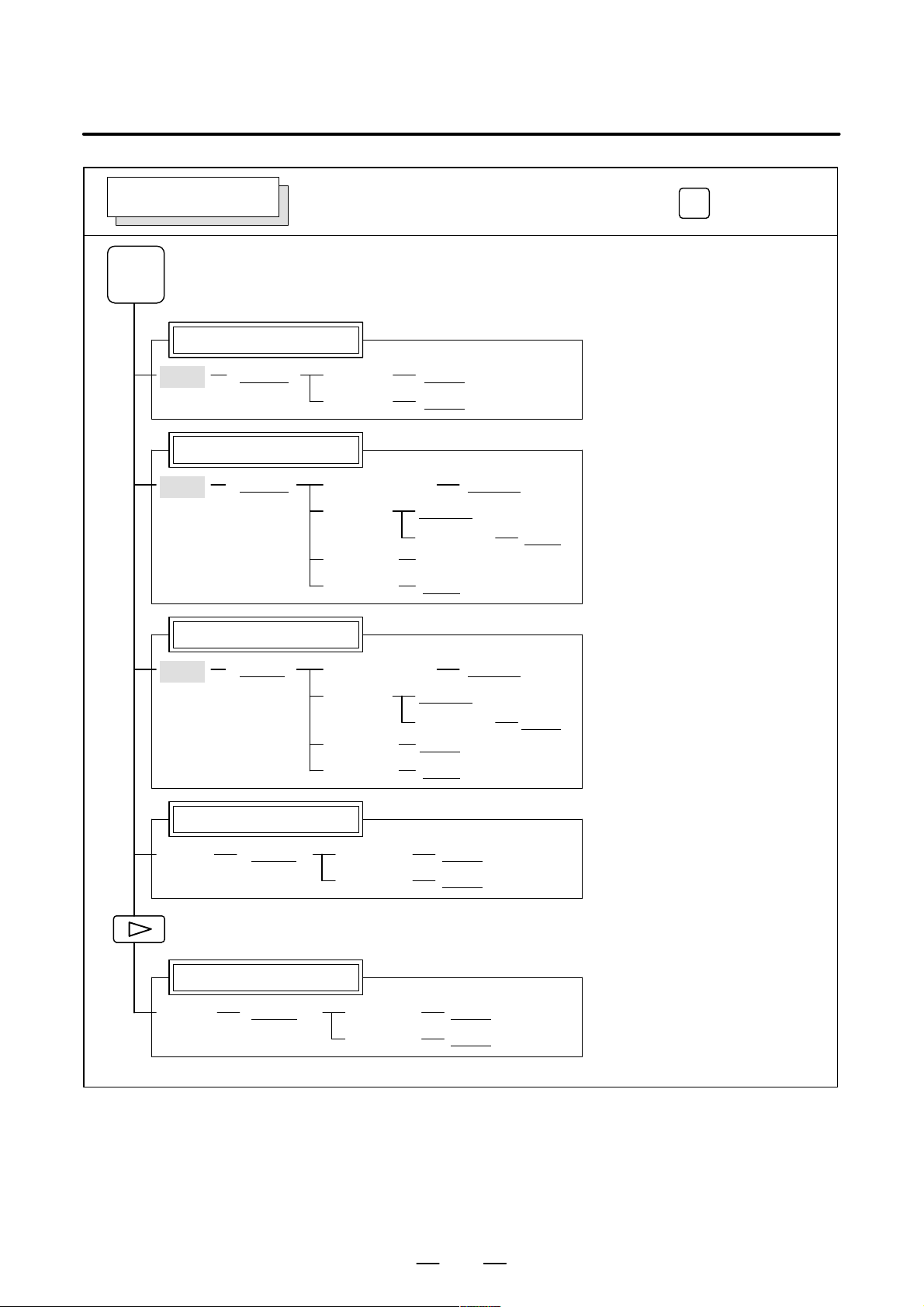
1.1
FUNCTION KEYS AND SOFT KEYS
1.1.1
Soft Keys
Operations and soft key display staturs for each function key are described
below:
T o display a more detailed screen, press a function key followed by a soft
key. Soft keys are also used for actual operations.
The following illustrates how soft key displays are changed by pressing
each function key.
The symbols in the following figures mean as shown below :
: Indicates screens
[]
()
[ ]
: Indicates a screen that can be displayed by pressing a
: Indicates a soft key(*2)
: Indicates input from the MDI panel.
: Indicates a soft key displayed in green (or highlighted).
: Indicates the continuous menu key (rightmost soft key)(*3).
function key(*1)
*1 Press function keys to switch between screens that are used frequently.
*2 Some soft keys are not displayed depending on the option configuration.
*3 In some cases, the continuous menu key is omitted when the 12 soft keys
type is used.
2
Page 27
B–63835EN/03
1. DISPLAY AND OPERATION
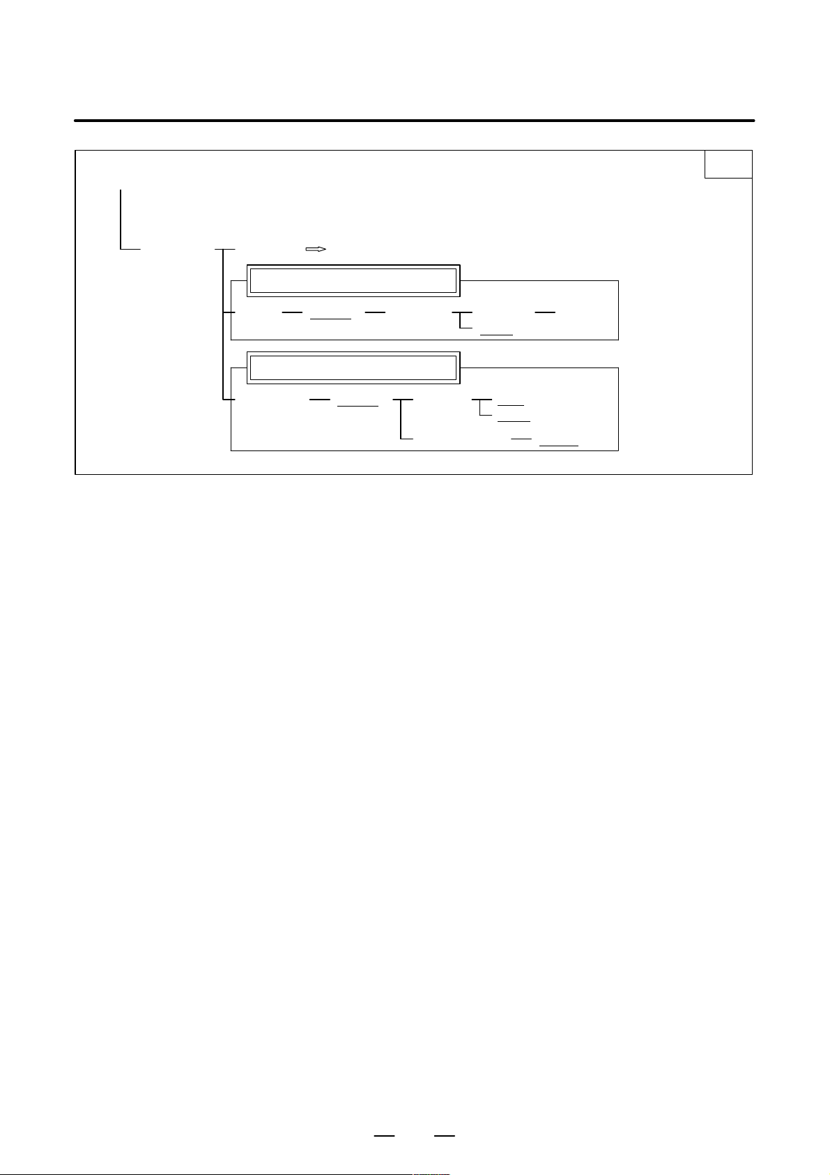
POSITION SCREEN
POS
Absolute coordinate display
[ABS]
Relative coordinate display
Current position display
[(OPRT)] [PTSPRE] [EXEC]
[(OPRT)][REL]
Soft key transition triggered by the function key
[RUNPRE] [EXEC]
(Axis or numeral)
[ORIGIN]
[PTSPRE] [EXEC]
[RUNPRE] [EXEC]
[ALLEXE]
[Axis name] [EXEC]
[PRESET]
POS
[ALL]
[(OPRT)]
Handle interruption
[HNDL]
Monitor screen
[MONI]
[(OPRT)] [PTSPRE] [EXEC]
[(OPRT)] [PTSPRE] [EXEC]
(Axis or numeral)
[ORIGIN]
[PTSPRE] [EXEC]
[RUNPRE] [EXEC]
[RUNPRE] [EXEC]
[RUNPRE] [EXEC]
[ALLEXE]
[Axis name] [EXEC]
[PRESET]
3
Page 28
1. DISPLAY AND OPERATION
B–63835EN/03
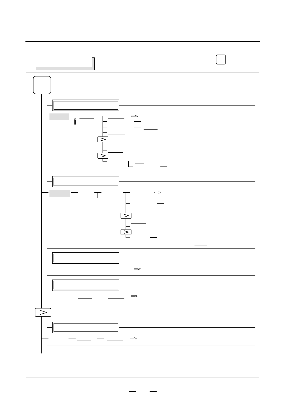
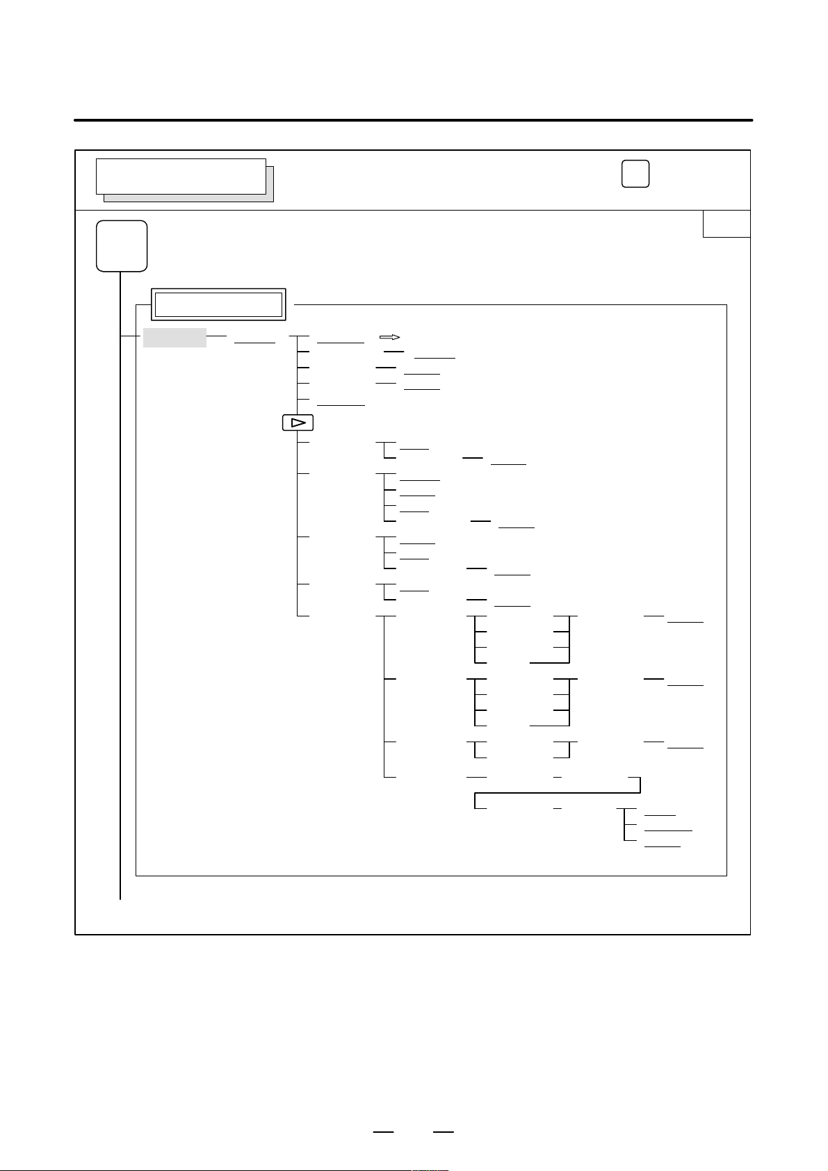
PROGRAM SCREEN
PROG
Program display screen
[PRGRM]
(1)
Program check display screen
Soft key transition triggered by the function key
in the MEM mode
[(OPRT)] [BG–EDT]
[O number]
[N number]
[REWIND]
[P TYPE]
[Q TYPE]
[F SRH]
[ABS]
[REL]
[(OPRT)][CHECK]
See “When the soft key [BG–EDT] is pressed”
[O SRH]
[N SRH]
[CAN]
(N number)
[BG–EDT]
[O number]
[N number]
[REWIND]
[EXEC]
See “When the soft key [BG–EDT] is pressed”
[O SRH]
[N SRH]
PROG
1/2
Current block display screen
[(OPRT)]
Next block display screen
[(OPRT)] [BG–EDT][NEXT]
Program restart display screen
[(OPRT)] [BG–EDT][RSTR]
(2)(Continued on the next page)
[P TYPE]
[Q TYPE]
[F SRH]
[BG–EDT][CURRNT]
See “When the soft key [BG–EDT] is pressed”
[CAN]
(N number)
[EXEC]
See “When the soft key [BG–EDT] is pressed”
See “When the soft key [BG–EDT] is pressed”
4
Page 29
B–63835EN/03
1. DISPLAY AND OPERATION
(2)
[FL.SDL] [PRGRM]
Return to (1) (Program display)
File directory display screen
[(OPRT)][DIR] [SELECT]
Schedule operation display screen
[SCHDUL] [CLEAR]
[(OPRT)]
(Schedule data)
2/2
(File No. ) [F SET]
[EXEC]
[CAN]
[EXEC]
[INPUT]
5
Page 30
1. DISPLAY AND OPERATION
B–63835EN/03
PROGRAM SCREEN
PROG
Program display
[PRGRM]
Soft key transition triggered by the function key
in the EDIT mode
[(OPRT)] [BG–EDT]
(O number) [O SRH]
(Address) [SRH↓]
(Address) [SRH↑]
[REWIND]
[F SRH] [CAN]
[READ] [CHAIN]
[PUNCH] [STOP]
[DELETE] [CAN]
[EX–EDT] [COPY] [CRSR∼]
PROG
See “When the soft key [BG–EDT] is pressed”
(N number) [EXEC]
(The cursor moves to the end of a program.)
[STOP]
[CAN]
(O number)
[CAN]
(O number)
(N number)
[MOVE] [CRSR∼]
[MERGE] [∼CRSR]
[CHANGE] (Address) [BEFORE]
[EXEC]
[EXEC]
[EXEC]
(O number) [EXEC]
[∼CRSR]
[∼BTTM]
[ALL]
(O number) [EXEC]
[∼CRSR]
[∼BTTM]
[ALL]
(O number) [EXEC]
[∼BTTM]
1/2
(1)(Continued on the next page)
(Address) [AFTER] [SKIP]
[1–EXEC]
[EXEC]
6
Page 31

B–63835EN/03
1. DISPLAY AND OPERATION
(1)
Program directory display
[LIB]
Graphic Conversational Programming (T series)
[C.A.P.]
[(OPRT)] [BG–EDT]
(O number) [O SRH]
[READ] [CHAIN]
[PUNCH] [STOP]
[PRGRM]
[G.MENU]
(G number) [BLOCK] (Data)
When a G number is omitted,
the standard screen appears.
Return to the program
See “When the soft key [BG–EDT] is pressed”
Return to the program
[STOP]
[CAN]
(O number)
[CAN]
(O number)
[EXEC]
[EXEC]
[LINE]
[CHAMF]
[CNR.R]
[INPUT]
2/2
Graphic Conversational Programming (M series)
[C.A.P.]
Floppy directory display
[FLOPPY]
[PRGRM]
[G.MENU]
[(OPRT)] [INPUT]
(G number) [BLOCK] (Data) [INPUT]
When a G number is omitted, the standard screen appears.
[PRGRM]
[DIR] (Numeral)
Return to the program
Return to the program
[(OPRT)]
[F SRH]
[READ]
[PUNCH]
[DELETE]
[CAN]
[EXEC]
(Numeral)
(Numeral)
[STOP]
[CAN]
[EXEC]
(Numeral)
(Numeral)
[STOP]
[CAN]
[EXEC]
(Numeral)
[CAN]
[EXEC]
INSERT
[F SET]
[F SET]
[O SET]
[F SET]
[O SET]
[F SET]
7
Page 32

1. DISPLAY AND OPERATION
B–63835EN/03
PROGRAM SCREEN
PROG
Program display
Program input screen
Current block display screen
[(OPRT)] [BG–EDT][PRGRM]
[(OPRT)] [BG–EDT][MDI]
[(OPRT)]
Soft key transition triggered by the function key
in the MDI mode
See “When the soft key [BG–EDT] is pressed”
See “When the soft key [BG–EDT] is pressed”
[START]
(Address)
(Address)
[REWIND]
[BG–EDT][CURRNT]
[CAN]
[EXEC]
[SRH↓]
[SRH↑]
See When the soft key [BG-EDT] is pressed"
PROG
Next block display screen
[(OPRT)] [BG–EDT][NEXT]
Program restart display screen
[(OPRT)] [BG–EDT][RSTR]
See “When the soft key [BG–EDT] is pressed”
See “When the soft key [BG–EDT] is pressed”
8
Page 33

B–63835EN/03
1. DISPLAY AND OPERATION
PROGRAM SCREEN
PROG
Program display
Current block display screen
Next block display screen
Program restart display screen
Soft key transition triggered by the function key
PROG
in the HNDL, JOG, or REF mode
[(OPRT)] [BG–EDT][PRGRM]
[(OPRT)] [BG–EDT][CURRNT]
[(OPRT)] [BG–EDT][NEXT]
See “When the soft key [BG–EDT] is pressed”
See “When the soft key [BG–EDT] is pressed”
See “When the soft key [BG–EDT] is pressed”
[(OPRT)] [BG–EDT][RSTR]
See “When the soft key [BG–EDT] is pressed”
9
Page 34

1. DISPLAY AND OPERATION
B–63835EN/03
PROGRAM SCREEN
PROG
Program input screen
[PRGRM]
Program directory display
[LIB]
[(OPRT)] [BG–EDT]
Soft key transition triggered by the function key
in the TJOG or THDL mode
[(OPRT)] [BG–EDT]
(O number)
(Address)
(Address)
[REWIND]
(O number) [O SRH]
PROG
See “When the soft key [BG–EDT] is pressed”
[O SRH] Return to the program
[SRH↓]
[SRH↑]
See “When the soft key [BG–EDT] is pressed”
Return to the program
10
Page 35

B–63835EN/03
1. DISPLAY AND OPERATION
PROGRAM SCREEN
PROG
Program display
[PRGRM]
Soft key transition triggered by the function key
(When the soft key [BG–EDT] is pressed in all modes)
[(OPRT)] [BG–END]
(O number) [O SRH]
(Address) [SRH↓]
(Address) [SRH↑]
[REWIND]
[F SRH] [CAN]
[READ] [CHAIN]
[PUNCH] [STOP]
[DELETE] [CAN]
[EX–EDT] [COPY] [CRSR∼]
(N number) [EXEC]
(The cursor moves to the end of a program.)
[STOP]
[CAN]
(O number)
[CAN]
(O number)
(N number)
[MOVE] [CRSR∼]
[MERGE] [∼CRSR]
[CHANGE] (Address) [BEFORE]
[EXEC]
[EXEC]
[EXEC]
(O number) [EXEC]
[∼CRSR]
[∼BTTM]
[ALL]
(O number) [EXEC]
[∼CRSR]
[∼BTTM]
[ALL]
(O number) [EXEC]
[∼BTTM]
PROG
1/2
(1)(Continued on the next page)
(Address) [AFTER] [SKIP]
[1–EXEC]
[EXEC]
11
Page 36

1. DISPLAY AND OPERATION
B–63835EN/03
(1)
Program directory display
[LIB]
Graphic Conversational Programming
[C.A.P.]
[(OPRT)] [BG–EDT]
(O number) [O SRH]
[READ] [CHAIN]
[PUNCH] [STOP]
[PRGRM]
[G.MENU]
(G number) [BLOCK] (Data)
When a G number is omitted, the standard
screen appears.
[STOP]
[CAN]
(O number)
[CAN]
(O number)
Return to the program
2/2
Return to the program
[EXEC]
[EXEC]
[LINE]
[CHAMF]
[CNR.R]
[INPUT]
Floppy directory display
[FLOPPY]
[PRGRM]
[DIR]
Return to the program
[(OPRT)]
[F SRH]
[READ]
[PUNCH]
[DELETE]
(Numeral)
[CAN]
[EXEC]
(Numeral)
(Numeral)
[STOP]
[CAN]
[EXEC]
(Numeral)
(Numeral)
[STOP]
[CAN]
[EXEC]
(Numeral)
[CAN]
[EXEC]
[F SET]
[F SET]
[O SET]
[F SET]
[O SET]
[F SET]
12
Page 37

B–63835EN/03
1. DISPLAY AND OPERATION
OFFSET/SETTING SCREEN (T series)
OFFSET
SETTING
Tool offset screen
[WEAR]
[GEOM] (Axis name and numeral) [MEASUR]
[(OPRT)][OFFSET]
Soft key transition triggered by the
function key
(Number)
(Axis name)
(Numeral)
(Numeral)
[CLEAR] [ALL]
[READ] [CAN]
[PUNCH] [CAN]
OFFSET
SETTING
[NO SRH]
[INP.C.]
[+INPUT]
[INPUT]
[WEAR]
[GEOM]
[EXEC]
[EXEC]
1/2
Setting screen
[(OPRT)][SETING]
Workpiece coordinate system setting screen
[WORK]
Macro variables display screen
[(OPRT)]
[(OPRT)][MACRO]
(Number)
[ON:1]
[OFF:0]
(Numeral)
(Numeral)
(Number)
(Axis name and numeral) [MEASUR]
(Numeral)
(Numeral)
(Number)
(Axis name) [INP .C.]
(Numeral)
[PUNCH]
[NO SRH]
[+INPUT]
[INPUT]
[NO SRH]
[+INPUT]
[INPUT]
[NO SRH]
[INPUT]
[CAN]
[EXEC]
(1)(Continued on the next page)
13
Page 38

1. DISPLAY AND OPERATION
B–63835EN/03
(1)
Pattern data input screen
[(OPRT)][MENU]
Software operator’s panel screen
[OPR]
T ool life management setting screen
[(OPRT)][TOOLLF]
Y–axis tool offset screen
[WEAR]
[GEOM] (Axis name and numeral) [MEASUR]
(Number)
[CLEAR]
(Numeral)
[(OPRT)][OFST.2]
[SELECT](Number)
[NO SRH]
[CAN]
[EXEC]
[INPUT]
(Number)
(Axis name)
(Numeral)
(Numeral)
2/2
[NO SRH]
[INP.C.]
[+INPUT]
[INPUT]
Workpiece shift screen
[(OPRT)][WK.SHFT]
Chuck/tailstock barrier setting screen
[(OPRT)][BARRIER]
(Numeral)
(Numeral)
(Numeral)
(Numeral)
[SET]
[CLEAR] [ALL]
[WEAR]
[GEOM]
[READ] [CAN]
[EXEC]
[PUNCH] [CAN]
[EXEC]
[+INPUT]
[INPUT]
[INPUT]
[+INPUT]
14
Page 39

B–63835EN/03
1. DISPLAY AND OPERATION
OFFSET/SETTING SCREEN (M series)
OFFSET
SETTING
Tool offset screen
[(OPRT)][OFFSET]
Setting screen
(Number)
(Axis name)
(Numeral)
(Numeral)
[CLEAR] [ALL]
[READ] [CAN]
[PUNCH] [CAN]
Soft key transition triggered by the
function key
[NO SRH]
[INP.C.]
[+INPUT]
[INPUT]
[WEAR]
[GEOM]
[EXEC]
[EXEC]
OFFSET
SETTING
1/2
[(OPRT)][SETING]
Workpiece coordinate system setting screen
[WORK]
Macro variables display screen
[(OPRT)]
[(OPRT)][MACRO]
(Number)
[ON:1]
[OFF:0]
(Numeral)
(Numeral)
(Number)
(Axis name and numeral) [MEASUR]
(Numeral)
(Numeral)
(Number)
(Axis name) [INP .C.]
(Numeral)
[PUNCH]
[NO SRH]
[+INPUT]
[INPUT]
[NO SRH]
[+INPUT]
[INPUT]
[NO SRH]
[INPUT]
[CAN]
[EXEC]
(1)(Continued on the next page)
15
Page 40

1. DISPLAY AND OPERATION
B–63835EN/03
(1)
Patten data input screen
[(OPRT)][MENU]
Software operator’s panel screen
[OPR]
T ool life management setting screen
[TOOLLF]
[(OPRT)]
(Number)
[CLEAR]
(Numeral)
2/2
[SELECT](Number)
[NO SRH]
[CAN]
[EXEC]
[INPUT]
16
Page 41

B–63835EN/03
1. DISPLAY AND OPERATION
SYSTEM SCREEN
SYSTEM
Parameter screen
Diagnosis screen
Soft key transition triggered by the function key
[(OPRT)][PARAM]
(Number)
[ON:1]
[OFF:0]
(Numeral)
(Numeral)
[READ] [CAN]
[PUNCH] [CAN]
[NO SRH]
[+INPUT]
[INPUT]
[EXEC]
[EXEC]
SYSTEM
1/3
[(OPRT)][DGNOS]
PMC screen
[PMCLAD][PMC]
(1)
(Continued on the next page)
(2)
[SEARCH]
[ADRESS]/[SYMBOL]
(3)
[NO SRH](Number)
[TOP]
[BOTTOM]
[SRCH]
[W–SRCH]
[N–SRCH]
[F–SRCH]
[TRGON][TRIGER]
[TRGOFF]
[START]
[DPARA]/[NDPARA]
[TRGSRC]
[INIT]
[DIVIDE][WINDOW]
[CANCEL]
[DELETE]
[SELECT]
[WIDTH]
[SEARCH][DUMP]
[BYTE]
[WORD]
[D.WORD]
17
Page 42

1. DISPLAY AND OPERATION
B–63835EN/03
(1)
(2) (3)
[PMCDGN] [TITLE]
With
PMC–RC
only
[PMCPRM] [TIMER]
[STOP]/[RUN]
[I/O] [EXEC]
[DUMP]
[DRARA]/[NDPARA]
[STATUS]
[ALARM]
[TRACE] [T.DISP]/[TRCPRM]
[M.SRCH] [SEARCH]
[ANALYS] [SCOPE]
[COUNTR]
[KEEPRL]
[DATA]
[SETTING] [YES]/[MANUAL]/[ROM]
[CANCEL]
(No.)
[SEARCH]
[BYTE]
[WORD]
[D.WORD]
[SEARCH]
[EXEC]
[INPUT]
[DELETE]
[INIT]
[ADRESS]/[SYMBOL]
[G.DATA]
[G.CONT]
[NO.SRH]
[INIT]
[NO]/[AUTO]/[RAM]
[SGNPRM]
[START]/[STOP]
[T–SRCH]
[ADRESS]/[SYMBOL]
[EXCHG] [SELECT]
[C.DATA]
[G–SRCH]
[SEARCH]
2/3
[TO] [EXEC]
[CANCEL]
System configuration screen
[SYSTEM]
ID information screen: αi servo information screen
[SYSTEM]
ID information screen: αi spindle information screen
[SYSTEM]
(4) (Continued on the next page)
[SV–INF]
[SP–INF]
[SPEED] [INPUT]
[INIT]
[MDI]/[ROM]
18
Page 43

B–63835EN/03
1. DISPLAY AND OPERATION
(4)
Pitch error compensation screen
[PITCH]
Servo parameter screen
[SV.PRM]
[(OPRT)]
[SV.SET]
[SV.TUN]
[SV.TRC] [(OPRT)]
(No.)
[ON:1]
[OFF:0]
(Numeral)
(Numeral)
[READ] [CAN]
[PUNCH] [CAN]
[(OPRT)]
[NO SRH]
[+INPUT]
[INPUT]
[EXEC]
[EXEC]
[ON:1]
[OFF:0]
(Numeral)
[TRACE]
[TRNSF]
3/3
[INPUT]
Spindle parameter screen
[SP.PRM]
Waveform diagnosis screen
[W.DGNS]
[SP.SET]
[SP.TUN]
[SP.MON]
[W.PRM]
[W.GRPH] [STSRT]
[(OPRT)]
[TIME→]
[←TIME]
[H–DOBL]
[H–HALF]
[STSRT]
[CH–1↑]
[CH–1↓]
[V–DOBL]
[V–HALF]
[ON:1]
[OFF:0]
[INPUT]
[STSRT]
[CH–2↑]
[CH–2↓]
[V–DOBL]
[V–HALF]
19
Page 44

1. DISPLAY AND OPERATION
B–63835EN/03
MESSAGE SCREEN
MESSAGE
Alarm display screen
[ALARM]
Message display screen
[MSG]
Alarm history screen
[HISTRY]
HELP SCREEN
Soft key transition triggered by the function key
[(OPRT)] [CLEAR]
Soft key transition triggered by the function key
MESSAGE
HELP
HELP
Alarm detail screen
[ALARM]
Operation method screen
[OPERAT]
Parameter table screen
[PARAM]
[(OPRT)] [SELECT]
[(OPRT)] [SELECT]
20
Page 45

B–63835EN/03
1. DISPLAY AND OPERATION
GRAPHIC SCREEN (T series)
T ool path graphics
Mode 0
GRAPH
[G.PRM]
[GRAPH] [ZOOM]
[ZOOM]
Soft key transition triggered by the function key
T ool path graphics
[(OPRT)] [NORMAL]
[(OPRT)]
[(OPRT)]
[ACT]
[HI/LO]
GRAPH
[HEAD]
[ERASE]
[PROCES]
[EXEC]
[STOP]
21
Page 46

1. DISPLAY AND OPERATION
B–63835EN/03
GRAPHIC SCREEN (M series)
T ool path graphics
GRAPH
[PARAM]
[EXEC] [AUTO]
[POS]
Solid graphics
GRAPH
Soft key transition triggered by the function key
T ool path graphics
[(OPRT)]
[(OPRT)][ZOOM] [EXEC]
GRAPH
[STSRT]
[STOP]
[REWIND]
[CLEAR]
[←]
[→]
[↑]
[↓]
Solid graphics
[PARAM]
[BLANK] [ANEW]
[PARAM]
[(OPRT)]
[+ROT]
[–ROT]
[+TILT]
[–TILT]
[(OPRT)][EXEC] [A.ST]]
[F.ST]
[STOP]
[REWIND]
[(OPRT)][REVIEW] [ANEW]
[+ROT]
[–ROT]
[+TILT]
[–TILT]
[(OPRT)][3–PLN] [ ]
[←]
[→]
[↑]
[↓]
22
Page 47

B–63835EN/03
1.2
SCREEN DISPLAYED IMMEDIATELY AFTER POWER IS TURNED ON
1. DISPLAY AND OPERATION
1.2.1
Slot Status Display
D Slot state screen
Types of PCBs mounted on the slots are displayed.
If a hardware trouble or an incorrect mounting is found, this screen is
displayed.
SLOT CONFIGURATION DISPLAY
0: 003E4000 0:
1: 30464202 1:
2: 00504303 2:
3: 3:
4: 4:
5: 5:
… …
Physical slot number (2ndary side)
Module ID of the PCB mounted (*1)
Physical slot number (primary side)
*1) Module ID of PCB
ff j j ∆ ∆
D Module ID
D Software ID
Internal slot number
Module function (software ID)
Type of PCB (module ID)
ID Name
06 Series 0i–B main CPU board
07 Series 0i Mate–B main CPU board
2E Data server board
CD Serial communication board/DNC2
AA HSSB interface board
96 Fast Ethernet board
40 : Main CPU
5E : HSSB interface (with PC)
23
Page 48

1. DISPLAY AND OPERATION
1.2.2
Setting Module Screen
1.2.3
Configuration Display of Software
D4A1–01
COPYRIGHT FANUC LTD 2002–2002
SLOT 01 (3046) : END
SLOT 02 (0050) :
B–63835EN/03
END : Setting
completed
Space :
Setting incompleted
Module ID
Slot number
D4A1–01
COPYRIGHT FANUC LTD 2002–2002
SERVO : 90B0–01
OMM : yyyy–yy
PMC : zzzz–zz
CNC control
software
Digital servo
ROM
Order made
macro/macro
compiler
PMC
24
Page 49

B–63835EN/03
1. DISPLAY AND OPERATION
1.3
SYSTEM CONFIGURATION SCREEN
1.3.1
Display Method
1.3.2
Configuration of PCBs
D Screen
After the system has been installed correctly, you can find the PCBs
installed and the softwares integrated on the system configuration screen.
(1)Press
SYSTEM
key.
(2) Press soft key [SYSTEM], then the system configuration screen is
displayed.
(3) The system configuration screen is composed of three screens and
each of them can be selected by the page key
PAGE
PAGE
Software series of module with CPU
.
D Module ID
SYSTEM CONFIG (SLOT) PAGE01
SLOT MODULE ID SERIES VERSION
00 3008 : 40 D4A1 0001
01 00CF : 66 B435 0001
Software ID (type)
Module ID
Slot No.
(80 to 8F is 2nd side)
ID Name
06 Series 0i–B main CPU board
07 Series 0i Mate–B main CPU board
CD Serial communication board/DNC2
2E Data server board
AA HSSB interface board
96 Fast Ethernet board
Software version
of module with
CPU
D Software ID
40 : Main CPU
5E : HSSB interface (with PC)
25
Page 50

1. DISPLAY AND OPERATION
B–63835EN/03
1.3.3
Software Configuration Screen
1.3.4
Module Configuration Screen
SYSTEM CONFIG (SOFTWARE) 01234 N12345
PAGE:02
SYSTEM D4A1 0001
BASIC+OPTION–A1
SERVO 90B0 0001
PMC(SYS) 406G 0001
406G 0001
PMC(LAD) FS16 0001
MACRO LIB BZG1 0001
MACRO APL AAAA BBBB
BOOT 60M5 0001
GRAPHIC–1 60V5 0001
GRAPHIC–2 60V6 0001
EMBED ETH 656A 0001
MEM **** *** *** 12:14:59
[ PARMA ][ DGNOS ][ PMC ][ SYSTEM ][(OPRT)]
Configuration of the modules displayed on PCB.
SYSTEM CONFIG (MODULE) 01234 N12345
PAGE:03
Kind of software
Software series
Software version
Software
configuration
Character written
on PMC title screen
Character written
on macro compiler
or on CAP .
(1)
SLOT 00 MOTHER BOARD
AXIS CTRL CARD : 08
DISPLAY CTRL CARD : 0E
CPU CARD : 11
FROM DIMM : C7
SRAM DIMM : 05
DRAM DIMM : A9
PMC CPU : 01
MEM **** *** *** 12:14:59
[ PARMA ][ DGNOS ][ PMC ][ SYSTEM ][(OPRT)]
(2)
(4)
(3)
Contents of display
(1)Slot number (The number is corresponding to PCB configuration
screen)
(2)Type of PCB mounted
(3)Name of card PCB or DIMM module
(4)Hardware ID of mounted card PCB or DIMM module
Refer to “2.5.4 Printed Circuit Boards of the Control Unit” for
correspondence with each hardware ID and drawing number.
Pressing the P AGE key
PAGE
PAGE
displays the system configuration
screen of other PCBs.
26
Page 51

B–63835EN/03
1. DISPLAY AND OPERATION
1.3.5
ID Information Screen
(αi Servo Information
Screen/αi Spindle
Information Screen)
D αi series servo and αi series spindle
When the αi servo/αi spindle system is connected, ID information
owned by connected units (motor, amplifier, module, etc.) for αi
servo/αi spindle can be displayed on the CNC screen.
See below for details.
D αi servo information screen (Chapter 5 Digital Servo)
D αi spindle information screen (Chapter 6 AC Spindle (Serial
Spindle))
27
Page 52

1. DISPLAY AND OPERATION
1.4
ALARM HISTORY SCREEN
1.4.1
Alarm History Screen
B–63835EN/03
1.4.1.1
General
1.4.1.2
Screen display
Alarms generated in the NC are recorded. The latest 25 alarms generated
are recorded. The 26th and former alarms are deleted.
(1)Press
MESSAGE
key .
(2)Press soft key [HISTRY] and an alarm history screen is displayed.
PAGE
(3)Other pages are displayed by
ALARM HISTORY O1234 N12345
02/04/18 20:56:26
506 OVERTRAVEL : +X
02/04/18 19:58:11
000 TURN OFF POWER
02/04/18 19:52:45
000 TURN OFF POWER
02/04/18 19:48:43
300 APC ALARM : X–AXIS ZERO RETURN REQUEST
02/04/18 18:10:10
507 OVERTRAVEL : +B
PAGE
or
key.
1.4.1.3
Clearing alarm history
1.4.1.4
Alarm display
[ ALARM ][ MSG ][ HISTRY ][ ][(OPRT)]
(1)Press soft key [(OPRT)].
(2)Press soft key [(CLEAR], then the alarm history is cleared.
When an external alarm (No. 1000 to 1999) or a macro alarm (No. 3000
to 3999) is output, the alarm history function can record both the alarm
number and message if so specified in the following parameter. If
recording of the message is not set or if no message is input, only an
external alarm or macro alarm is displayed.
28
Page 53

B–63835EN/03
1. DISPLAY AND OPERATION
3112
[Data type] Bit
#3 (EAH) The alarm history function:
1.4.2
System Alarm History
1.4.2.1
General
#7
#6 #5 #4 #3
EAH
#2 #1 #0
0 : Does not record the messages output with external alarms or macro
alarms.
1 : Records the messages output with external alarms or macro alarms.
Up to three system alarms issued in the past are stored, and information
about those alarms can be displayed on the system alarm history screen.
SYSTEM ALARM HISTORY O1234 N12345
1 2002–03–13 12:13:19
930 CPU INTERRUPT
2 2002–03–11 07:23:07
900 ROM PARITY
3 2002–02–27
973 NON MASK INTERRUPT
1.4.2.2
System alarm history screen (history list screen)
Procedure
EDIT **** *** *** 08:20:52
[ ][ ][ NMIHIS ][ ][ ]
By setting bit 2 (NMH) of parameter No. 3103 to 1, information about up
to three system alarms including the latest system alarm can be displayed.
The latest system alarm information is displayed at the top of the list, and
a lower item in the list indicates older system alarm information.
1 Set bit 2 (NMH) of parameter No. 3103 to 1.
2 Press the function key <MESSAGE>.
3 Press the [NMIHIS] chapter selection soft key.
The following information is displayed:
1. System alarm occurrence date and time
2. System alarm number
3. System alarm message (No message is displayed for some
system alarms.)
29
Page 54

1. DISPLAY AND OPERATION
B–63835EN/03
SYSTEM ALARM HISTORY O1234 N12345
1 2002–03–13 12:13:19
930 CPU INTERRUPT
2 2002–03–11 07:23:07
900 ROM PARITY
3 2002–02–27
973 NON MASK INTERRUPT
EDIT **** *** *** 08:20:52
[ ][ ][ NMIHIS ][ ][ ]
[ SELECT ][ RETURN ][ CLEAR ][ ][ ]
[SELECT] soft key
[CLEAR] soft key
This soft key displays the details of a system alarm.
Procedure
1 Press the [(OPRT)] soft key on the system configuration screen.
2 By using the cursor keys
PAGE
PAGE
, move the cursor to the system
alarm number whose details are to be displayed.
3 Press the [SELECT] soft key.
4 The details of the selected system alarm are displayed.
This soft key clears all system alarm information stored.
When bit 4 (OPC) of parameter No. 3110 is set to 1, this soft key is
displayed. When bit 4 (OPC) of parameter No. 3110 is set to 0, this soft
key is not displayed.
Procedure
1 Set bit 4 (OPC) of parameter No. 3110 to 1.
[RETURN] soft key
2 Press the [(OPRT)] soft key on the system configuration screen.
3 Press the [CLEAR] soft key.
4 Information about all of the three system alarms stored is cleared.
Pressing the [RETURN] soft key while system alarm history screen
(detail screen) is displayed returns the screen display to the system alarm
list screen.
30
Page 55

B–63835EN/03
1. DISPLAY AND OPERATION
1.4.2.3
System alarm history screen (detail screen)
The system alarm history screen (detail screen) displays information
items such as registers and stacks involved when a system alarm is issued.
The following items are displayed:
1. System alarm occurrence date and time
2. System alarm number
3. System alarm message (No message is displayed for some system
alarms.)
4. System alarm occurrence series and edition
5. Number of display pages
6. General–purpose resistor, pointer index register, segment register,
task register, LDT register, flag register, interrupt source, error
code, error address
7. Contents of stacks (up to 32 stacks)
8. Contents of stacks of privilege level 3 (up to 48 stacks)
9. NMI information
Y ou can switch among the information items 6 to 9 by the page keys
PAGE
PAGE
.
Pressing the [RETURN] soft key returns the screen display to the state
alarm history list screen.
SYSTEM ALARM HISTORY O1234 N12345
2 2002–03–11 07:23:07 BDH1–01(1/4)
973 NON MASK INTERRUPT
EAX EBX ECX EDX
00000000 00930063 000003E0 00000040
ESI EDI EBP ESP
00000010 009404E0 0000FFB4 0000FFDC
SS DS ES FS GS TR LDTR
06D8 0338 0248 0440 0338 0628 0028
EFLAGS VECT ERRC ERROR–ADDRESS
00003046 FFFF 0000 03E0:000009BC
EDIT **** *** *** 08:20:52
[ SELECT ][ RETURN ][ CLEAR ][ ][ ]
(Detail display screen 1)
31
Page 56

1. DISPLAY AND OPERATION
B–63835EN/03
SYSTEM ALARM HISTORY O1234 N12345
2 2002–03–11 07:23:07 BDH1–01(2/4)
973 NON MASK INTERRUPT
STACK (PL0)
3646 0338 7CBA 0001 0958 FFF8 0068 0063
0346 0000 0000 02BC 08F8 52F1 2438 0338
0580 0440 0580 001F 03C0 0214 0780 0FFF
0000 0000 0000 0000 0000 0000 0000 0000
EDIT **** *** *** 08:20:52
[ SELECT ][ RETURN ][ CLEAR ][ ][ ]
(Detail display screen 2)
SYSTEM ALARM HISTORY O1234 N12345
2 2002–03–11 07:23:07 BDH1–01(3/4)
973 NON MASK INTERRUPT
STACK!(PL3)
SS:ESP3 =0804:00007C50
CS:EIP =1350:00001234
1008 1408 0001 0002 0003 0004 1008 FFE4
1008 3678 00FA 0024 0000 0000 0000 0000
0000 0000 0000 0000 0000 0000 0000 0000
0000 0000 0000 0000 0000 0000 0000 0000
0000 0000 0000 0000 0000 0000 0000 0000
0000 0000 0000 0000 0000 0000 0000 0000
EDIT **** *** *** 08:20:52
[ SELECT ][ RETURN ][ CLEAR ][ ][ ]
(Detail display screen 3)
SYSTEM ALARM HISTORY O1234 N12345
2 2002–03–11 07:23:07 BDH1–01(4/4)
973 NON MASK INTERRUPT
NMIC
00000000 00000000 00000000 00000000
SVL
11111111 11111111
SVR
11111111 11111111 11111111 11111111
11111111 11111111 11111111 11111111
ADRS
007F0000
EDIT **** *** *** 08:20:52
[ SELECT ][ RETURN ][ CLEAR ][ ][ ]
(Detail display screen 4)
32
Page 57

B–63835EN/03
1. DISPLAY AND OPERATION
CAUTION
1 In the case of an NMI on other than the main board, the
registers of detail display screen 1, and the contents of detail
display scree n 2 and de ta il display scree n 3 are displa yed .
SYSTEM ALARM HISTORY O1234 N12345
2 2002–03–11 07:23:07 BDH1–01(1/1)
972 NMI OCUURRED IN OTHER MODULE
SLOT> 02
<1> <2>
EDIT **** *** *** 08:20:52
[ SELECT ][ RETURN ][ CLEAR ][ ][ ]
0080415F
(Detail display screen 5)
<1> NMI occurrence slot number
<2> Message address set with the NMI occurrence slot (string address)
SYSTEM ALARM HISTORY O1234 N12345
2 2002–03–11 07:23:07 BDH1–01(1/1)
900 ROM PARITY
00000000 00000000
<1>
EDIT **** *** *** 08:20:52
[ SELECT ][ RETURN ][ CLEAR ][ ][ ]
(Detail display screen 6)
<1> ROM parity cause
Basic ROM 2F(h). . . . . . . . . . . . . . . . . . . . . . . .
(800000 to 97FFFF)
Additional ROM 40(h). . . . . . . . . . . . . . . . . . . .
(A00000 to A3FFFF)
OMM ROM 80(h). . . . . . . . . . . . . . . . . . . . . . .
Servo ROM 100(h). . . . . . . . . . . . . . . . . . . . . . . .
Built in MMC ROM 200(h). . . . . . . . . . . . . . . . .
Online Custom Screen 400(h). . . . . . . . . . . . . . . .
33
Page 58

1. DISPLAY AND OPERATION
1.4.2.4
Parameter
3103
[Data type] Bit
#7
#6 #5 #4 #3 #2
NMH The system alarm history screen is:
0 : Not displayed.
1 : Displayed.
B–63835EN/03
#1 #0
NMH
#7
3110
[Data type] Bit
OPC On the operation history screen, the [CLEAR] soft key is:
#6 #5 #4
0 : Not enabled.
1 : Enabled.
#3 #2 #1 #0
OPC
34
Page 59

B–63835EN/03
1. DISPLAY AND OPERATION
1.5
EXTERNAL OPERATOR MESSAGES RECORD
1.5.1
Screen Display
This function enables the saving of external operator messages as a
record.
The record can be viewed on the external operator message history screen.
(1)Press the
(2)Press the rightmost soft key
MESSAGE
function key.
.
(3)Press the [MSGHIS] soft key.
PAGE
(4)To display the previous or subsequent screen, press the
PAGE
or
key.
MESSAGE HISTORY O1234 N12345
02/04/01 17:25:00 PAGE : 1
No. ****
Up to 255 characters
→ Date,
time, and
page
→ Message
No.
Displa y
range
1.5.2
Deletion of External Operator Messages Record
MEM STRT MTN FIN ALM 17:25:00
[ ][ MSGHIS ][ ][ ][ ]
(1)The recorded external operator message can be deleted by setting the
MMC bit (bit 0 of parameter 3113) to 1.
Pressing the [CLEAR] soft key erases all the records of the external
operator message.
(2)The MS1 and MS0 bits (bits 7 and 6 of parameter 3113) specify the
number of records to be displayed on the external operator message
history screen. When the bits are changed, all external operator
message records retained up to that point are erased.
35
Page 60

1. DISPLAY AND OPERATION
1.5.3
Parameter
#0 (MHC) The records of an external operator message:
#6, #7 (MS0,MS1) These bits set the number of characters to be retained in each record of an
B–63835EN/03
#7
MS13113
#6
MS0
#5 #4 #3 #2 #1 #0
MHC
0 : Cannot be erased.
1 : Can be erased.
external operator message, as well as the number of records, as shown in
the following table:
MS1 MS0 Number of charac-
ters in each record
0 0 255 8
0 1 200 10
1 0 100 18
1 1 50 32
* An external operator message of up to 255 characters can be specified.
Combining the MS1 bit and MS0 bit (bits 7 and 6 of parameter No.
3113) selects the number of records by limiting the number of
characters to be retained as the record of an external operator message.
#7
3112
#6 #5 #4 #3 #2
OMH
#2 (OMH) The external operator message history screen is:
0 : Not displayed.
1 : Displayed.
NOTE
After setting this parameter, briefly turn the power off, then
on again.
Number of records
#1 #0
1.5.4
Notes
When the number of an external operator message is specified, the system
starts updating the records of the specified message. The system
continues to perform update until another external operator message is
specified or until an instruction to delete the records of the external
operator message is specified.
36
Page 61

B–63835EN/03
1. DISPLAY AND OPERATION
1.6
OPERATION HISTORY
1.6.1
Parameter Setting
This function displays the key and signal operations performed by the
operator upon the occurrence of a fault or the output of an alarm, together
with the corresponding alarms.
This function records the following data:
(1)MDI key operations performed by the operator
(2)Status changes (ON/OFF) of input and output signals (selected signals
only)
(3)Details of alarms
(4)Time stamp (date and time)
#7
OHS3106
#6 #5 #4
[Data type] Bit
OPH The operation history screen is:
0 : Not displayed.
1 : Displayed.
#3 #2 #1 #0
OPH
OHS The operation history is:
0 : Sampled.
1 : Not sampled.
3122 Interval at which the clock time is recorded in the operation history
[Data type] Word
[Units of data] Minutes
[Valid data range] 0 to 1439
The clock time is recorded to the operation history at specified intervals.
If zero is set as the interval, ten minutes is assumed. The time is recorded
only when data is recorded within the corresponding interval.
#7
3206
#6 #5 #4
PHS
#3 #2 #1 #0
[Data type] Bit
PHS Setting and display on the operation history signal selection screen and
the parameters (No. 12801 through No. 128900) are:
0 : Not linked.
1 : Linked.
37
Page 62

1. DISPLAY AND OPERATION
B–63835EN/03
12801 Number of a signal symbol table for selecting an operation history signal (01)
12802 Number of a signal symbol table for selecting an operation history signal (02)
12803 Number of a signal symbol table for selecting an operation history signal (03)
12804 Number of a signal symbol table for selecting an operation history signal (04)
12805 Number of a signal symbol table for selecting an operation history signal (05)
12806 Number of a signal symbol table for selecting an operation history signal (06)
12807 Number of a signal symbol table for selecting an operation history signal (07)
12808 Number of a signal symbol table for selecting an operation history signal (08)
12809 Number of a signal symbol table for selecting an operation history signal (09)
12810 Number of a signal symbol table for selecting an operation history signal (10)
12811 Number of a signal symbol table for selecting an operation history signal (11)
12812 Number of a signal symbol table for selecting an operation history signal (12)
12813 Number of a signal symbol table for selecting an operation history signal (13)
12814 Number of a signal symbol table for selecting an operation history signal (14)
12815 Number of a signal symbol table for selecting an operation history signal (15)
12816 Number of a signal symbol table for selecting an operation history signal (16)
12817 Number of a signal symbol table for selecting an operation history signal (17)
12818 Number of a signal symbol table for selecting an operation history signal (18)
12819 Number of a signal symbol table for selecting an operation history signal (19)
12820 Number of a signal symbol table for selecting an operation history signal (20)
[Data type] Byte
[Valid data range] 1 to 10
Set the number of a symbol table including a signal of which operation
history is to be recorded for operation history channel (01) to (20) as
follows:
1 : G0 to G255
2 : G1000 to G1255
3 : F0 to F255
4 : F1000 to F1255
5 : Y0 to Y127
6 : X0 to X127
9 : G2000 to G2255
10 : F2000 to F2255
38
Page 63

B–63835EN/03
1. DISPLAY AND OPERATION
12841 Number of a signal selected as an operation history signal (01)
12842 Number of a signal selected as an operation history signal (02)
12843 Number of a signal selected as an operation history signal (03)
12844 Number of a signal selected as an operation history signal (04)
12845 Number of a signal selected as an operation history signal (05)
12846 Number of a signal selected as an operation history signal (06)
12847 Number of a signal selected as an operation history signal (07)
12848 Number of a signal selected as an operation history signal (08)
12849 Number of a signal selected as an operation history signal (09)
12850 Number of a signal selected as an operation history signal (10)
12851 Number of a signal selected as an operation history signal (11)
12852 Number of a signal selected as an operation history signal (12)
12853 Number of a signal selected as an operation history signal (13)
12854 Number of a signal selected as an operation history signal (14)
12855 Number of a signal selected as an operation history signal (15)
12856 Number of a signal selected as an operation history signal (16)
12857 Number of a signal selected as an operation history signal (17)
12858 Number of a signal selected as an operation history signal (18)
12859 Number of a signal selected as an operation history signal (19)
12860 Number of a signal selected as an operation history signal (20)
[Data type] Word
[Valid data range] 0 to 255
Set the number of a signal of which operation history is to be recorded for
operation history channel (01) to (20) with a value between 0 and 255.
39
Page 64

1. DISPLAY AND OPERATION
B–63835EN/03
#7
RB712881
History record bit settings for an operation history signal (01)
#7
RB712882
History record bit settings for an operation history signal (02)
#7
RB712883
History record bit settings for an operation history signal (03)
#7
RB712884
History record bit settings for an operation history signal (04)
#7
RB712885
History record bit settings for an operation history signal (05)
#7
RB712886
History record bit settings for an operation history signal (06)
#7
RB712887
#6
RB6
#6
RB6
#6
RB6
#6
RB6
#6
RB6
#6
RB6
#6
RB6
#5
RB5
#5
RB5
#5
RB5
#5
RB5
#5
RB5
#5
RB5
#5
RB5
#4
RB4
#4
RB4
#4
RB4
#4
RB4
#4
RB4
#4
RB4
#4
RB4
#3
RB3
#3
RB3
#3
RB3
#3
RB3
#3
RB3
#3
RB3
#3
RB3
#2
RB2
#2
RB2
#2
RB2
#2
RB2
#2
RB2
#2
RB2
#2
RB2
#1
RB1
#1
RB1
#1
RB1
#1
RB1
#1
RB1
#1
RB1
#1
RB1
#0
RB0
#0
RB0
#0
RB0
#0
RB0
#0
RB0
#0
RB0
#0
RB0
History record bit settings for an operation history signal (07)
#7
RB712888
History record bit settings for an operation history signal (08)
#7
RB712889
History record bit settings for an operation history signal (09)
#7
RB712890
History record bit settings for an operation history signal (10)
#7
RB712891
History record bit settings for an operation history signal (11)
#7
RB712892
History record bit settings for an operation history signal (12)
#7
RB712893
History record bit settings for an operation history signal (13)
#7
RB712894
#6
RB6
#6
RB6
#6
RB6
#6
RB6
#6
RB6
#6
RB6
#6
RB6
#5
RB5
#5
RB5
#5
RB5
#5
RB5
#5
RB5
#5
RB5
#5
RB5
#4
RB4
#4
RB4
#4
RB4
#4
RB4
#4
RB4
#4
RB4
#4
RB4
#3
RB3
#3
RB3
#3
RB3
#3
RB3
#3
RB3
#3
RB3
#3
RB3
#2
RB2
#2
RB2
#2
RB2
#2
RB2
#2
RB2
#2
RB2
#2
RB2
#1
RB1
#1
RB1
#1
RB1
#1
RB1
#1
RB1
#1
RB1
#1
RB1
#0
RB0
#0
RB0
#0
RB0
#0
RB0
#0
RB0
#0
RB0
#0
RB0
History record bit settings for an operation history signal (14)
#7
RB712895
History record bit settings for an operation history signal (15)
#6
RB6
#5
RB5
#4
RB4
#3
RB3
#2
RB2
40
#1
RB1
#0
RB0
Page 65

B–63835EN/03
1. DISPLAY AND OPERATION
#7
RB712896
History record bit settings for an operation history signal (16)
#7
RB712897
History record bit settings for an operation history signal (17)
#7
RB712898
History record bit settings for an operation history signal (18)
#7
RB712899
History record bit settings for an operation history signal (19)
#7
RB712900
History record bit settings for an operation history signal (20)
#6
RB6
#6
RB6
#6
RB6
#6
RB6
#6
RB6
#5
RB5
#5
RB5
#5
RB5
#5
RB5
#5
RB5
#4
RB4
#4
RB4
#4
RB4
#4
RB4
#4
RB4
#3
RB3
#3
RB3
#3
RB3
#3
RB3
#3
RB3
#2
RB2
#2
RB2
#2
RB2
#2
RB2
#2
RB2
#1
RB1
#1
RB1
#1
RB1
#1
RB1
#1
RB1
#0
RB0
#0
RB0
#0
RB0
#0
RB0
#0
RB0
[Data type] Bit
RB7 to RB0 For the signal set in channel (01) to (20), of which operation history is to
be recorded, the history of each bit is:
0 : Not recorded. (The history of this bit is not recorded.)
1 : Recorded. (The history of this bit is recorded.)
41
Page 66

1. DISPLAY AND OPERATION
1.6.2
Screen Display
D Displaying the operation
history
B–63835EN/03
(1) Press the
(2)Press the continue menu key [
SYSTEM
function key.
]. The [OPEHIS] (OPERATION
HISTORY) soft key are displayed.
(3)Press the [OPEHIS] soft key twice. The operation history screen is
displayed.
OPERATION HISTORY O1234 N12345
Page : 123
No.DATA No.DATA No.DATA
01 01/06/03 11 F0000.7↑ 21 F0001.0↓
02 08:40:00 12 F0000.5↑ 22 <POS>
03 <DELETE> 13 F0001.0↑ 23 <PROG>
04 F0000.6↑ 14 F0000.5↓ 24 <RESET>
05 MEM 15 P/S0010 25 EDIT
06 G0009.0↑ 16 02/06/03 26 O
07 G0009.1↑ 17 09:27:49 27 1
08 G0009.2↑ 18 <PROG> 28 2
09 ST↑ 19 <RESET> 29 3
10 ST↓ 20 F0000.7↓ 30 4
EDIT **** *** *** 08:20:52
[ TOP ][ BOTTOM ][ ][ ][PG.SRH]
On the operation history screen, the soft keys are configured as shown
below:
⇒ [
][PARAM ] [DGNOS] [PMC] [SYSTEM] [(OPE)][ ]
ãpush
[
] [W.DGNS] [ ] [ ] [OPEHIS] [(OPE)] [ ]
ã push
][OPEHIS ] [SG–SEL] [ ] [ ] [(OPE)][ ]
[
ãpush
[ ] [ TOP ] [BOTTOM] [ ] [ ] [PG.SRH] [ ]
(4)To display the next part of the operation history, press the page down
PAGE
key
T o display the interface between two pages, press cursor key
. The next page is displayed.
or
. The screen is scrolled by one row . On a 14–inch CRT screen,
pressing the cursor key scrolls the screen by half a page.
These soft keys can also be used:
1) Pressing the [TOP] soft key displays the first page (oldest data).
2) Pressing the [BOTTOM] soft key displays the last page (latest
data).
3) Pressing the [PG.SRH] soft key displays a specified page.
Example) By entering 50 then pressing the [PG.SRH] key, page 50 is
displayed.
42
Page 67

B–63835EN/03
1. DISPLAY AND OPERATION
Data displayed on the operation history screen
(1)MDI keys
Address and numeric keys are displayed after a single space.
Soft keys are displayed in square brackets ([]).
Other keys (RESET/INPUT, for example) are displayed in angle
brackets (<>).
A key pressed at power–on is displayed in reverse video.
For two–path control, the operations of path 2 are displayed in the
same way, but preceded by S_.
1) Function key: <POS>, <PROG>, <OFFSET>, etc.
2) Address/numeric key: A to Z, 0 to 9, ; (EOB), +, –, (, etc.
3) Page/cursor key: <PAGE↑>, <CUR↓>, <CUR←>
4) Soft key: [SF1], [SF2], etc.
5) Other key: <RESET>, <CAN>, etc.
6) Key pressed at power–on:
<RESET>
(2)Input and output signals
General signals are displayed in the following format:
G 0 0 0 0 . 7 ↑
The↑ mark indicates that the signal is
turned on.
The↓ mark indicates that the signal is
turned off.
Indicates the bit.
Indicates the address.
Some signals are indicated by their symbol names.
SBK ↑ (Indicates that the single block switch is turned on.)
43
Page 68

1. DISPLAY AND OPERATION
B–63835EN/03
Mode selection signals and rapid traverse override signals
are displayed as indicated below:
Input signal
Name displayed
MD1 ND2 MD4 REF DNC1
0 0 0 0 0 MDI
1 0 0 0 0 MEM
1 0 0 0 1 RMT
0 1 0 0 0 NOMODE
1 1 0 0 0 EDT
0 0 1 0 0 H/INC
1 0 1 0 0 JOG
1 0 1 1 0 REF
0 1 1 0 0 TJOG
1 1 1 0 0 THND
Input signal
Name displayed
ROV1 ROV2
0 0 R100%
1 0 R50%
0 1 R25%
1 1 RF0%
(3)NC alarms
NC alarms are displayed in reverse video.
P/S alarms, system alarms, and external alarms are displayed together
with their numbers.
For other types of alarms, only the alarm type is displayed. (No details
are displayed.)
For two–path control, the operations of path 2 are displayed in the
same way, but preceded by S_.
Example)
P/S0050, SV_ALM, S_APC_ALM
(4)Time stamp (date and time)
The following time data (date and time) is recorded:
1) Date and time of power–on
2) Date and time of power–off
3) Date and time when an NC alarm occurs
4) The clock time is recorded at predetermined intervals, together
with each new calendar day.
44
Page 69

B–63835EN/03
1. DISPLAY AND OPERATION
1) The power–on time is displayed as shown below:
02/01/20 ==== Year/Month/Day
09:15:30 ==== Hour:Minute:Second
2) The power–off time and the time when an NC alarm occurred are
displayed in reverse video.
02/01/20 ==== Year/Month/Day
09:15:30 ==== Hour:Minute:Second
If a system alarm occurs, the date and time are not recorded.
3) At predetermined intervals, the clock time is displayed in reverse
video. Set the interval in minutes in parameter No. 3122. If zero
is set, the time is stamped at ten–minute intervals.
09:15:30 ==== Hour:Minute:Second
Each new calendar day is displayed in reverse video.
02/01/20 ==== Year/Month/Day
CAUTION
1 The clock time is recorded for a specified interval only when
data is stored within that interval.
2 If a system alarm is issued, the system alarm occurrence
time is used for power–off display.
D Input signal or output
signal to be recorded in
the operation history
(1)P ress the
(2) Press the continuous menu key [
SYSTEM
function key.
]. The [OPEHIS] (operation
history) soft key is displayed.
(3)Press the [OPEHIS] soft key, then press the [SG–SEL] soft key . The
operation history signal selection screen is displayed.
OP_HIS SIGNAL SELECT O1000 N02000
No. ADDRES SIGNAL No. ADDRES SIGNAL
01 X0000 00001000 11 G0000 00000001
02 X0004 10000000 12 G0004 00000011
03 X0008 00001100 13 G0008 00000111
04 X0009 00111000 14 G0003 00001111
05 X0012 00001111 15 G0043 01100000
06 Y0000 01000000 16 ********
07 Y0004 00110000 17 ********
08 Y0007 00011100 18 ********
09 Y0008 00011100 19 ********
10 Y0010 00011100 20 ********
>
EDIT **** *** * * * 00:00:00
[OPEHIS] [SG–SEL] [ ] [ ] [ (OPE) ]
45
Page 70

1. DISPLAY AND OPERATION
B–63835EN/03
1.6.3
Setting the Input Signal or Output Signal to be Recorded in the Operation History
(1)On the operation history signal selection screen, press the [(OPE)] soft
key.
OP_HIS SIGNAL SELECT O1000 N02000
No. ADDRES SIGNAL No. ADDRES SIGNAL
01 G0004 00000010 11 ********
02 ******** 12 ********
03 ******** 13 ********
04 ******** 14 ********
05 ******** 15 ********
06 ******** 16 ********
07 ******** 17 ********
08 ******** 18 ********
09 ******** 19 ********
10 ******** 20 ********
>
EDIT **** *** *** *** 00:00:00
[ ALLDEL ][ DELETE ][ ON:1 ][ OFF:0 ][ ]
(2)Press the cursor key or to position the cursor to a desired
position.
(3)Key in a signal type (X, G, F, or Y) and an address, then press the
INPUT
key.
Example) G0004
INPUT
Signal address G0004 is set in the ADDRES column. The corre sponding
position in the SIGNAL column is initialized to 000000000.
(4)Select the bit to be recorded.
T o select all bits of the specified signal address, press the [ON:1] soft
key while the cursor is positioned to
00000000 .
T o select a particular bit, position the cursor to that bit by pressing the
cursor key
or , then press the [ON:1] soft key. To cancel
a selection made by pressing the [ON:1] soft key or to cancel a
previously selected signal, press the [OFF:0] soft key.
(5)Up to 20 addresses can be specified by means of this signal selection.
These addresses need not always be specified at consecutive positions,
starting from No.1.
(6)Pressing the [ALLDEL] and [EXEC] soft keys deletes all data. If the
[ALLDEL] key is pressed by mistake, it can be cancelled by pressing
the [CAN] key.
(7)To delete a selected signal address, position the cursor to the
corresponding position then press the [DELETE] and [EXEC] soft
keys. In the SIGNAL column, asterisks ******** are displayed in
place of the deleted data. In the ADDRES column, the corresponding
position is cleared.
If the [DELET] key is pressed by mistake, it can be cancelled by
pressing the [CAN] key.
(8)Pressing the return menu key [
] causes the [OPEHIS] (OPE) soft
key to be displayed again.
46
Page 71

B–63835EN/03
1. DISPLAY AND OPERATION
D Parameter–based setting
D Input signals and output
signals to be recorded in
the history
to
By setting bit 4 (PHS) of parameter No. 3206, setting and display on the
operation history signal selection screen can be linked with parameter No.
12801 through No. 12900. By this linking, setting information related to
input and output signals subject to operation history processing can be
input and output in the same way as ordinary parameters.
NOTE
1 A cross (×) indicates that a signal will not be recorded. Also,
any signal for which an address is not specified will not be
recorded, either.
2 A circle (f) indicates that a signal can be recorded.
3 A signal indicated by its symbol name will also be displayed
by its symbol name.
1. M/T addresses
MT→PMC
#7
fX000
fX127 f f f f f f f
#6
#5
f
f
#4
#3
f
f
#2
#1
f
f
#0
f
PMC→CNC
#7
fG000
to
fG003 f f f f f f f
fG004 f f f FIN f f f
fG005 f f f TFIN SFIN f MFIN
fG006 f f f f *ABS f SRN
RLSOTG007 EXLM *FLUP f f ST STLK f
ERSG008 RRW *SP *ESP f f f *IT
fG009 f f f f f f f
to
fG013 f f f f f f f
fG014 f f f f f f f
fG015 f f f f f f f
to
fG018 f f f f f f f
#6
#5
f
f
#4
#3
f
f
#2
#1
f
f
#0
f
RTG019 f f f f f f f
47
Page 72

1. DISPLAY AND OPERATION
to
to
B–63835EN/03
#7 #6 #5 #4 #3 #2 #1 #0
fG020 f f f f f f f
fG042 f f f f f f f
fG043 × f × × f f f
fG044 f f f f f MLK BDT1
BDT9G045 BDT8 BDT7 BDT6 BDT5 BDT4 BDT3 BDT2
DRNG046 KEY4 KEY3 KEY2 KEY1 f SBK f
fG047 f f f f f f f
fG060 f f f f f f f
fG061 f f f f f f RGTA
fG062 f f f f f f f
to
fG099 f f f f f f f
+J8G100 +J7 +J6 +J5 +J4 +J3 +J2 +J1
fG101 f f f f f f f
–J8G102 –J7 –J6 –J5 –J4 –J3 –J2 –J1
fG103 f f f f f f f
to
fG105 f f f f f f f
MI8G106 MI7 MI6 MI5 MI4 MI3 MI2 MI1
fG107 f f f f f f f
MLK8G108 MLK7 MLK6 MLK5 MLK4 MLK3 MLK2 MLK1
fG109 f f f f f f f
+LM8G110 +LM7 +LM6 +LM5 +LM4 +LM3 +LM2 +LM1
fG111 f f f f f f f
–LM8G112 –LM7 –LM6 –LM5 –LM4 –LM3 –LM2 –LM1
fG113 f f f f f f f
*+L8G114 *+L7 *+L6 *+L5 *+L4 *+L3 *+L2 *+L1
48
Page 73

B–63835EN/03
1. DISPLAY AND OPERATION
#7 #6 #5 #4 #3 #2 #1 #0
fG115 f f f f f f f
*–L8G116 *–L7 *–L6 *–L5 *–L4 *–L3 *–L2 *–L1
fG117 f f f f f f
*+ED8G118 *+ED7 *+ED6 *+ED5 *+ED4 *+ED3 *+ED2 *+ED1
fG119 f f f f f f f
*–ED8G120 *–ED7 *–ED6 *–ED5 *–ED4 *–ED3 *–ED2 *–ED1
fG121 f f f f f f f
to
fG125 f f f f f f f
SVF8G126 SVF7 SVF6 SVF5 SVF4 SVF3 SVF2 SVF1
fG127 f f f f f f f
to
fG129 f f f f f f f
*IT8G130 *IT7 *IT6 *IT5 *IT4 *IT3 *IT2 *IT1
fG131 f f f f f f f
fG132 f f f +MIT4 +MIT3 +MIT2 +MIT1
f
fG133 f f f f f f f
fG134 f f f –MIT4 –MIT3 –MIT2 –MIT1
fG135 f f f f f f f
to
fG255 f f f f f f f
PMC→MT
#7
fY000
to
fY127 f f f f f f f
#6
#5
f
f
#4
#3
f
f
#2
#1
f
f
#0
f
CNC→PMC
#7
fF000
to
fF255 f f f f f f f
#6
#5
f
f
#4
#3
f
f
#2
#1
f
f
#0
f
49
Page 74

1. DISPLAY AND OPERATION
B–63835EN/03
1.6.4
Inputting and Outputting the Operation History Data
D Output
D Input
Recorded data can be output to an input/output unit connected via a
reader/punch interface. An output record can be input from the
input/output unit.
Set the input/output unit to be used in setting parameters No. 0020 and
0100 to 0135.
To output the data, set a code in the ISO bit of a setting parameter (bit 1
of parameter No. 0020).
(1)Select EDIT mode.
SYSTEM
(2)Press the
(3)Press the soft keys [(OPRT)],
key, then select the operation history display screen.
, [PUNCH], and [EXEC] in this
order.
The data output to the FANUC Floppy Cassette or FANUC FA Card is
stored under file name OPERATION HISTORY.
(1)Select EDIT mode.
SYSTEM
(2)Press the
(3) Press the soft keys [(OPRT)],
key, then select the operation history display screen.
, [READ], and [EXEC] in this
order.
D Output data format
1. MDI/soft key
2. Signal
3. Alarm
4. For extension (date or time)
5. MDI/soft key of path 2
6. Signal of path 2
7. Alarm of path 2
The header and recorded operation data are output, in this order. The
operation history data is divided into four parts by identifier words. Data
other than the identifier words depends on the type.
T(identifier word)
T0 : Header
T50 : MDI/soft key
T51 : Signal
T52 : Alarm
T53 : For extension (date or time)
T54 : MDI/soft key of path 2
T55 : Signal of path 2
T56 : Alarm of path 2
50
Page 75

B–63835EN/03
1. DISPLAY AND OPERATION
1) Header
T 0 C O P E R A T I O N
H I S T O R Y ;
C: Data word
2) MDI/soft key
T 5 0 P 0 to 1 H * * ;
P0: Usually
P1: At power–on
H **: Key code (See the following table.)
3) Signal
0 to 2550 to 6T 5 1 P H * * ,N * * ;
P0: X0000 and above
P2: G0000 and above
P4: Y0000 and above
P6: F0000 and above
N***: DI/DO number
H **: Signal information data (hexadecimal)
New data Old data
51
Page 76

1. DISPLAY AND OPERATION
P0: P/S No. 100
P1: P/S No. 000
P2: P/S No. 101
P3: P/S No. 0001 to 254
P4: Overtravel alarm
P5: Overheat alarm
P6: Servo alarm
P7: System alarm
P8: APC alarm
P9: Spindle alarm
P10: P/S alarm No. 5000 to 5999
P15: External alarm
N****: Alarm number (for P/S alarm, system alarm, and external
alarm only)
B–63835EN/03
4) Alarm
0 to 10T 5 2 P * *N * * ;
Date
5) For extension (date or time)
0 to 1T 5 3 P 0 *E * * ;D * * * * *
T 5 3 P 1 *E * * ;D * * *Time
P0: Usually
P1: At power–on
E0: Date
E1: Time
D*..*: Data Example) June 29, 2002
0 to 1
D 2 0 0 0 62 2 9
52
Page 77

B–63835EN/03
1. DISPLAY AND OPERATION
Key codes (MDI/soft key)
(00H to 7FH)
0 1 2 3 4 5 6 7
0 Space 0 @ P
1 ! 1 A Q
2 ” 2 B R
3 # 3 C S
4 $ 4 D T
5 % 5 E U
6 & 6 F V
7 ’ 7 G W
8 ( 8 H X
9 ) 9 I Y
A ;
(EOB)
B + K [
C ’ < L ¥
D – = M ]
E . > N
F / ? O –
* : J Z
53
Page 78

1. DISPLAY AND OPERATION
B–63835EN/03
(80H to FFH)
8 9 A B C D E F
0 Reset
F0
*
1 MMC
F1
*
2 CNC
F2
*
3 F3
4 Shift Insert
F4
*
5 Delete
F5
*
6 CAN Alter
F6
*
7 F7
8 Cur→*Input
*
9 Cur←
*
A Cur↓*Help
*
POS
PROG
OFFSET
SETTING
F8
*
F9
*
*
*
*
*
*
*
*
*
*
*
*
B Cur↑
*
C MESSAGE
D CUSTOM
E Page↓
*
F Page↑
*
*1:On the small–sized keyboard, ED corresponds to the
GRAPH
a standard keyboard, ED corresponds to the
CUSTOM
key.
* : Command key
key and EE to the
SYSTEM
GRAPH
*1*
CUSTOM
Fapt
CUSTOM
GRAPH
*
*
FR
*
*
FL
*
*
key. On
54
Page 79

B–63835EN/03
1. DISPLAY AND OPERATION
1.6.5
Notes
(1)While the operation history screen is displayed, no information can be
recorded to the history.
(2)An input signal having an on/off width of up to 16 msec is not recorded
in the history. Some signals are not recorded in the history.
(3)Once the storage becomes full, old data is deleted, starting from the
oldest record. Up to about 8000 key information items can be
recorded.
(4)The recorded data is retained even after the power is turned off. A
memory all clear operation, however, erases the recorded data.
(5) The operation history function cannot execute sampling when the
OHS bit (bit 7 of parameter No. 3106) is set to 1.
(6)Set the date and time on the setting screen.
(7)The time needed to input and output 6000 operation records at a rate
of 4800 baud is as follows:
Output:About 5 minutes
Input: About 2 minutes and 30 seconds
This file corresponds to a paper tape of about 180 m in length.
55
Page 80

1. DISPLAY AND OPERATION
1.7
HELP FUNCTION
B–63835EN/03
1.7.1
General
1.7.2
Display Method
D Display of help screen
The help function displays alarm information, operation method and a
table of contents for parameters. This function is used as a handbook.
HELP
Press
key on any screen other than PMC screen, then a help screen
appears.
(However, it is not available when PMC screen/CUSTOM screen is
displaying)
HELP (INITIAL MENU) O1234 N12345
***** HELP *****
1. ALARM DETAIL
2. OPERATION METHOD
3. PARAMETER TABLE
D Help for alarm
[ALARM] [OPERAT] [PARAM] [ ] [ ]
(1) When an alarm is generated, press soft key [ALARM], then a help
message of the alarm is displayed.
HELP (INITIAL MENU) O1234 N12345
NUMBER : 010
M’SAGE : IMPROPER G CODE
FUNCTION :
ALARM :
A G CODE NOT LISTED IN G–CODE TABLE
IS BEING COMMANDED
ALSO G–CODE FOR FUNCTION NOT ADDED
IS BEING COMMANDED
[ALARM] [OPERAT] [PARAM] [ ] [ (OPRT) ]
(2)Pressing soft key [OPERAT],(alarm No.), and soft key [SELECT]
in this order, a help message corresponding to the input alarm number
is displayed.
56
Page 81

B–63835EN/03
1. DISPLAY AND OPERATION
D Help for operation
(1)Press [OPERAT], then a menu for operation method is displayed.
HELP (OPERATION METHOD) O1234 N12345
1. PROGRAM EDIT
2. SEARCH
3. RESET
4. DATA INPUT WITH MDI
5. DATA INPUT WITH TAPE
6. OUTPUT
7. INPUT WITH FANUC CASSETTE
8. OUTPUT WITH FANUC CASSETTE
9. MEMORY CLEAR
[ALARM] [OPRERAT] [PARAM] [ ] [(OPRT)]
(2)Press [OPERAT], (an item number) and soft key [SELECT], then an
operation method of the item is displayed.
PAGE
Pressing PAGE key
PAGE
or
HELP (OPERATION METHOD) O1234 N12345
<<1.PROGRAM EDIT>> 1/4
DELETE ALL PROGRAMS
MODE :EDIT
SCREEN :PROGRAM
OPR :(0–9999) – (DELETE)
displays another pages.
Current
page/ Total
page
DELETE ONE PROGRAM
MODE : EDIT
SCREEN : PROGRAM
OPR :(0+PROGRAM NUMBER) – <DELETE>
[ ] [ ] [ ] [ ] [SELECT]
57
Page 82

1. DISPLAY AND OPERATION
B–63835EN/03
D Parameter table
Press soft key [PARAM], then a parameter table is displayed.
HELP (PARAMETER TABLE) O1234 N12345
1/4
·SETTING (NO.0000~ )
·READER/PUNCHER INTERFACE (NO.0100~ )
·AXIS CONTROL/SETTING UNIT (NO.1000~ )
·COORDINATE SYSTEM (NO.1200~ )
·STROKE LIMIT (NO.1300~ )
·FEED RATE (NO.1400~ )
·ACCEL/DECELERATION CTRL (NO.1600~ )
·SERVO RELATED (NO.1800~ )
·DI/DO (NO.3000~ )
[ ALARM ] [OPERAT][ PARAM ] [ ][SELECT]
Another screen can be selected by the PAGE key
PAGE
or
PAGE
Current
page/ T otal
page
.
58
Page 83

B–63835EN/03
1.8
DISPLAYING DIAGNOSTIC PAGE
1. DISPLAY AND OPERATION
1.8.1
Displaying Diagnostic Page
1.8.2
Contents Displayed
D Causes when the
machine does not travel
in spite of giving a
command
(1)Press
SYSTEM
key.
(2)Press soft key [DGNOS], then a diagnostic screen is displayed.
000 WAITING FOR FIN SIGNAL An auxiliary function is being
executed.
001 MOTION Travel command of cycle
operation is being executed.
002 DWELL DWELL Dwell is being executed.
003 IN–POSITION CHECK In–position check is being done.
004 FEEDRATE OVERRIDE 0% Feedrate override is 0%.
005 INTERLOCK/START LOCK Interlock or start lock is input.
006 SPINDLE SPEED ARRIVAL CHECK Waiting for spindle speed
arrival signal.
010 PUNCHING Data is being output through
reader/puncher interface.
011 READING Data is being input through
reader/puncher interface.
012 WAITING FOR (UN) CLAMP Waiting for the end of index
table indexing
013 JOG FEEDRATE OVERRIDE 0% Manual feedrate override is 0%.
014 WAITING FOR RESET, ESP,RRW OFF NC is in reset state.
015 EXTERNAL PROGRAM NUMBER SEARCH External Program Number
Search External program
number search is being done
016 BACKGROUND ACTIVE Background is being used.
59
Page 84

1. DISPLAY AND OPERATION
D Cause of the cycle start
LED turned off
D State of TH alarm
B–63835EN/03
020 CUT SPEED UP/DOWN
021 RESET BUTTON ON
022 RESET AND REWIND ON
023 EMERGENCY STOP ON
024 RESET ON
025 STOP MOTION OR DWELL
Input of emergency stop signal
Input of external reset signal
Reset button On of MDI
Input of reset & rewind
Servo alarm generation
Switching to other mode, Feed hold
Single block stop
1 000100
0 010000
0 001000
1 000000
1 111000
1 111110
030 CHARACTER NUMBER TH ALARM Position of the character that
caused TH alarm. The position
is counted from the head.
031 TH DATA Data of the character that caused
TH alarm.
D Details of serial pulse
coder
DGN
#7(OVL): Overload alarm
#5(OVC): Over current alarm
#4(HCA): Abnormal current alarm
#3(HVA): Overvoltage alarm
#2(DCA): Discharge alarm
#1(FBA): Disconnection alarm
#0(OFA): Overflow alarm
#7
OVL200
#6
LV
#5
OVC#4HCA
#6(LV): Insufficient voltage alarm
#3
HVA
#2
DCA
#1
FBA
#0
OFA
60
Page 85

B–63835EN/03
1. DISPLAY AND OPERATION
#7
DGN
Overload 0 – – – Motor overheat
alarm
Disconnec- 1 – – 0 Built–in pulse coder (hand)
tion alarm
DGN
202
ALD201
1 – – – Amplifier overheat
1 – – 1 Disconnection of separated type pulse
0 – – 0 Disconnection of pulse coder (software)
#7
#6 #5 #4
#6
CSA
#5
BLA
EXP
#4
PHA
#3 #2 #1 #0
coder (hard)
#3
RCA
#2
BZA
#6(CSA): Hardware of serial pulse coder is abnormal
#5(BLA): Battery voltage is low (warning)
#4(PHA): Serial pulse coder or feedback cable is erroneous.
Counting of feedback cable is erroneous.
#3(RCA): Serial pulse coder is faulty.
Counting of feedback cable is erroneous.
#2(BZA): Battery voltage became 0.
Replace the battery and set the reference position.
#1
CKA#0SPH
DGN
DGN
#1(CKA): Serial pulse coder is faulty.
Internal block stopped.
#0(SPH): Serial pulse coder or feedback cable is faulty.
Counting of feedback cable is erroneous.
#7
DTE203
#6
CRC
#5
STB#4PRM
#3 #2 #1 #0
#7(DTE): Communication failure of serial pulse coder.
There is no response for communication.
#6(CRC): Communication failure of serial pulse coder.
Transferred data is erroneous.
#5(STB): Communication failure of serial pulse coder.
Transferred data is erroneous.
#4(PRM): The alarm is detected by the servo, the values specified in the parameter is
not correct.
#7
204
#6
OFS#5MCC
#4
LDA
#3
PMS
#2 #1 #0
#6(OFS): Abnormal current value result of A/D conversion of digital
#5(MCC): Contacts of MCC of servo amplifier is melted.
#4(LDA): Serial pulse coder LED is abnormal
#3(PMS): Feedback is not correct due to faulty serial pulse coder C or feedback
cable.
61
Page 86

1. DISPLAY AND OPERATION
D Details of separate serial
pulse coder alarms
DGN
#7(OHA): Overheat occurred in the separate pulse coder.
#6(LDA): An LED error occurred in the separate pulse coder.
#5(BLA): A low battery voltage occurred in the separate pulse coder.
#4(PHA): A phase data error occurred in the separate linear scale.
#3(CMA): A count error occurred in the separate pulse coder.
#2(BZA): The battery voltage for the separate pulse coder is zero.
#1(PMA): A pulse error occurred in the separate pulse coder.
#0(SPH): A soft phase data error occurred in the separate pulse coder.
DGN
#7(DTE): A data error occurred in the separate pulse coder.
B–63835EN/03
#7
OHA205
#7
DTE206
#6
LDA
#6
CRC
#5
BLA
#5
STB
#4
PHA#3CMA
#4 #3 #2 #1 #0
#2
BZA
#1
PMA#0SPH
#6(CRC): A CRC error occurred in the separate pulse coder.
#5(STB): A stop bit error occurred in the separate pulse coder.
D Details of invalid servo
parameter alarms (on the
CNC side)
DGN
280
#0(MOT): The motor type specified in parameter No. 2020 falls outside the
#2(PLC): The number of velocity feedback pulses per motor revolution, specified in
#3(PLS): The number of position feedback pulses per motor revolution, specified in
#4(DIR): The wrong direction of rotation for the motor is specified in parameter No.
#6(AXS): In parameter No. 1023 (servo axis number), a value that falls outside the
This data indicates the cause of servo alarm No. 417, detected by the NC.
If the alarm is detected by the servo, the PRM bit (bit 4 of DGN No. 0203)
is set to 1.
#7
#6
AXS
#5 #4
DIR
#3
PLS
#2
PLC
#1 #0
MOT
predetermined range.
parameter No. 2023, is zero or less. The value is invalid.
parameter No. 2024, is zero or less. The value is invalid.
2022 (the value is other than 111 or –111).
range of 1 to the number of controlled axes is specified. (For example, 4 is
specified instead of 3.) Alternatively, the values specified in the
parameter are not consecutive.
D Position error amount
DGN
300 Position error of an axis in detection unit
D Machine position
DGN
301 Distance from reference position of an axis in detection unit
Position error=
Feed rate [mm/min]
60 servo loop gain [1/sec]
62
×
1
Detection unit
Page 87

B–63835EN/03
D Reference position shift
function
1. DISPLAY AND OPERATION
DGN
302 Distance from the end of the deceleration dog to the first grid point
[Data type] Two–word axis
[Units of data] 0.001 mm (metric output), 0.0001 inch (inch output)
[Valid data range] –99999999 to 99999999
D Position deviation with
fine acceleration/
deceleration enabled
DGN
303 Position deviation with fine acceleration/deceleration enabled
[Data type] Two–word axis
[Unit of data] Detection unit
[Valid data range] –99999999 to 99999999
D Reference counter
DGN
304 Reference counter for individual axes
[Data type] Two–word axis
[Unit of data] Detection unit
[Valid data range] –99999999 to 99999999
D Displacement detection
DGN
305 Position feedback data between Z phases of individual axes
[Data type] Two–word axis
[Unit of data] Detection unit
[Valid data range] –99999999 to 99999999
If displacement detection is enabled, the feedback data between the Z
phases of different axes is represented in the detection unit.
63
Page 88

1. DISPLAY AND OPERATION
D Machine coordinates of
angular axis/orthogonal
axis
B–63835EN/03
DGN
DGN
306 Machine coordinates of a slant axis in the Cartesian coordinate system
307 Machine coordinates of an orthogonal axis in the Cartesian coordinate system
[Data type] Two–word
[Unit of data]
Increment system IS–A IS–B IS–C Unit
Metric input 0.01 0.01 0.01 mm
Inch input
Rotation axis
[Valid data range] –99999999 to 99999999
These parameters are updated only when bit 0 (AAC) of parameter No.
8200 is set to 1, and any of the parameters below is set to 1:
D Bit 0 (AOT) of parameter No. 8201
D Bit 1 (AO2) of parameter No. 8201
D Bit 2 (AO3) of parameter No. 8201
D Bit 3 (QSA) of parameter No. 5009 (T series only)
D The interference check option is selected.
0.001 0.001 0.001 inch
0.01 0.01 0.01 deg
D Motor temperature
information
DGN
[Unit of data] _C
[Valid data range] 0 to 255
DGN
[Unit of data] _C
[Valid data range] 0 to 255
308 Servo motor temperature
[Data type] Byte axis
The αi servo motor coil temperature is indicated.
When the temperature reaches 140_C, an alarm about motor overheat is
issued.
309 Pulse coder temperature
[Data type] Byte axis
The temperature of the pulse coder printed circuit board is indicated.
When the temperature reaches 100_C (85_C for the atmosphere
temperature in the pulse coder), an alarm about motor overheat is issued.
64
Page 89

B–63835EN/03
D Cause of the APZ bit (bit
4 of parameter 1815)
brought to 0
DGN
310
#0(PR1): The setting of the following parameters has been changed: Parameters
#1(PR2): The setting of the ATS bit (bit 1 of parameter 8302) has been changed.
#2(BZ1): The detected APC battery voltage is 0 V (Inductosyn).
1. DISPLAY AND OPERATION
NOTE
1 The temperature data must fall within the following ranges.
50_C to 160_C "5_C
160_C to 180_C "10_C
2 The temperature at which an overheat alarm is issued has
a maximum error of 5_C.
3 Information on axes other than the αi servo axis is not
indicated. (Indicated by ”0_C.”)
#7
#6
DTH
#5
ALP
#4
NOF
#3
BZ2
#2
BZ1
#1
PR2
#0
PR1
1821, 1850, 1860, 1861.
DGN
#3(BZ2): The detected APC battery voltage is 0 V (separate position detector).
#4(NOF): The Inductosyn output no offset data.
#5(ALP): Before the α pulse coder detects a full single rotation, reference position
establishment by parameters was attempted.
#6(DTH): A controlled axis detach signal/parameter was input.
#7
311
#6
DUA
#5
XBZ#4GSG
#3
AL4
#2
AL3
#1
AL2
#0
AL1
#0(AL1): An APC alarm was issued.
#2(AL3): The detected APC battery voltage is 0 V (serial pulse coder).
#3(AL4): An abnormal rotation speed (RCAL) was detected.
#4(GSG): The G202 signal was brought from 0 to 1.
#1(AL2): A disconnection was detected.
#6(DUA): While the dual position feedback function was being used, the difference
in error between the semi–closed loop side and the closed loop side
became too large.
#5(XBZ): The detected APC battery voltage is 0 V (serial separate position
detector).
65
Page 90

1. DISPLAY AND OPERATION
D FSSB status
DGN
#0(CLS): Closed.
#1(OPP): Running OPEN protocol.
#2(RDY): Open and ready.
#3(OPN): Open.
#4(ERP): Running ERROR protocol.
#7(CFE): Encountered configuration error.
B–63835EN/03
#7
CFE320
#6 #5 #4
ERP
#3
OPN
#2
RDY#1OPP
#0
CLS
Indicates the internal status of the FSSBC.
(The actual slave type does not match the one specified in the conversion
table.)
DGN
DGN
DGN
#7
XE3321
#6
XE2
#5
XE1
Indicates the cause of an FSSBC error.
#0(ER0): INFORMED ERROR
#1(ER1): (RESERVE)
#2(ER2): Master port disconnection
#3(ER3): External EMG input
Indicates the cause of an FSSBC error resulting from a request from a slave.
#4(XE0): (RESERVE)
#5(XE1): Slave port disconnection
#6(XE2): Master port disconnection
#7(XE3): External EMG input
#7
330
#7
332
#6 #5 #4 #3
#6 #5 #4 #3
#4
XE0
#3
ER3
EXT
EXT
#2
ER2
#2
DUA
#2
DUA
#1
ER1
#1
ST1
#1
ST1
#0
ER0
#0
ST0
#0
ST0
to
348
#7
#6 #5 #4 #3
EXT
#2
DUA
#1
ST1
#0, #1(ST0, ST1): Indicates the type code for an actually connected slave.
ST1 ST0 Type Address
0 0 A Servo amplifier
0 1 (B: RESERVE) (Currently nonexistent)
1 0 C Stand–alone type detector inter-
1 1 (RESERVE) (Currently nonexistent)
66
face unit
#0
ST0DGN
Page 91

B–63835EN/03
1. DISPLAY AND OPERATION
#2(DUA): 0 : The slave of interest is not on the first axis of the two–axis amplifier.
1 : The slave of interest is on the first axis of the two–axis amplifier.
#3(EXT): 0 : The slave of interest does not exist.
1 : The slave of interest exists.
DGN
DGN
DGN
331
333
to
349
#7
#7
#7
#6 #5
DMA
#6 #5
DMA
#6 #5
DMA
#4
TP1
#4
TP1
#4
TP1
#3
TP0
#3
TP0
#3
TP0
#2
HA2
#2
HA2
#2
HA2
#1
HA1
#1
HA1
#1
HA1
#0
HA0
#0
HA0
#0
HA0
#0, #1, #2(HA0, HA1, HA2): Indicates the host LSI address specified as a DMA destination.
#3, #4 (TP0, TP1): Indicates the type code of a specified slave.
(See the above descriptions about ST0 and ST1.)
#5(DMA): Indicates a value determining whether to allow DMA to occur.
NOTE
A combination of parameter Nos. 330 and 331 corresponds
to one FSSB slave unit. Up to ten slave units are available.
Slave units and the associated diagnosis numbers
Slave unit 00
Slave unit 01
Slave unit 02
Slave unit 03
Slave unit 04
Slave unit 05
Slave unit 06
Slave unit 07
Slave unit 08
Slave unit 09
³
³
³
³
³
³
³
³
³
³
Diagnosis No. 330, No. 331
Diagnosis No. 332, No. 333
Diagnosis No. 334, No. 335
Diagnosis No. 336, No. 337
Diagnosis No. 338, No. 339
Diagnosis No. 340, No. 341
Diagnosis No. 342, No. 343
Diagnosis No. 344, No. 345
Diagnosis No. 346, No. 347
Diagnosis No. 348, No. 349
67
Page 92

1. DISPLAY AND OPERATION
D Details of invalid servo
parameter setting alarms
(on the servo side)
B–63835EN/03
DGN
352 Detail number for invalid servo parameter setting alarm
D Detailed descriptions
about invalid servo
parameter setting alarms
Detail
number
Parameter
number
Indicates information that can be used to identify the location (parameter)
and cause of an invalid servo parameter setting alarm (servo alarm No.
417).
This diagnosis information is valid when the following conditions are
satisfied.
D Servo alarm No. 417 has occurred.
D Bit 4 of diagnosis No. 203 (PRM) = 1
See the following table for the displayed detail numbers and the
corresponding causes. For further detail information that could be used
to take measures, refer to FANUC AC Servo Motor αi series Parameter
Manual (B–65270EN).
Cause Measure
0233 2023 A value specified as the number of veloc-
ity pulses is greater than 13100 when initialization bit 0 = 1.
0243 2024 A value specified as the number of posi-
tion pulses is greater than 13100 when
initialization bit 0 = 1.
0434
0435
0444
0445
0474
0475
0534
0535
0544
0545
0686
0687
0688
0694
0695
0696
0699
2043 The internal value of the velocity loop in-
tegration gain has overflowed.
2044 The internal value of the velocity loop pro-
portional gain has overflowed.
2047 The internal value of the observer param-
eter (POA1) has overflowed.
2053 The internal value of the dead zone com-
pensation parameter has overflowed.
2054 The internal value of the dead zone com-
pensation parameter has overflowed.
2068 The internal value of the feedforward co-
efficient has overflowed.
2069 The interval value of the velocity feedfor-
ward coefficient has overflowed.
Decrease the value specified as the number of velocity pulses to within 13100.
Decrease the value specified as the number of position pulses to within 13100.
Decrease the value specified in the velocity loop integration gain parameter.
Use a function for changing the internal format of the velocity loop proportional gain.
Change the setting to: (–1) × (desired
setting)/10
Decrease the setting until the invalid parameter setting alarm will not occur any
longer.
Decrease the setting until the invalid parameter setting alarm will not occur any longer.
Use the position gain magnification function.
Decrease the velocity feedforward coefficient.
68
Page 93

B–63835EN/03
1. DISPLAY AND OPERATION
Detail
number
0754
0755
0764
0765
0783 2078 The conversion coefficient parameter
0793 2079 The conversion coefficient parameter
0843 2084 No positive value has been set for the
0853 2085 No positive value has been set as the
Parameter
number
2075 The setting of the parameter listed at the
left has overflowed.
2076 The setting of the parameter listed at the
left has overflowed.
listed at the left has not been set up for a
full–closed loop linear motor (for the Series 9080 only).
listed at the left has not been set up for a
full–closed loop linear motor (for the Series 9080 only).
flexible feed gear numerator.
Alternatively, the following condition exists: Feed gear numerator > denominator
flexible feed gear denominator.
MeasureCause
This parameter is presently not in use.
Specify 0 in it.
This parameter is presently not in use.
Specify 0 in it.
Set a value in this parameter.
Set a value in this parameter.
Specify a positive value as the flexible
feed gear numerator.
Alternatively, satisfy the following condition: Feed gear numerator x denominator (except for phase A–/B–specific
stand–alone type detector).
Specify a positive value as the flexible
feed gear denominator.
0884
0885
0886
0883 2088 A value of 100 or greater was specified in
0926
0927
0928
0996 2099 The internal value for suppressing N
1123 2112 No value has been entered for the AMR
1183 2118 No value has been specified in the semi–/
1284
1285
2088 The internal value of the machine velocity
feedback coefficient has overflowed.
the machine velocity feedback coefficient
for an axis with a serial stand–alone type
detector.
2092 The interval value of the advance feedfor-
ward coefficient has overflowed.
pulses has overflowed.
conversion coefficient parameter when a
linear motor is in use.
full–closed loop error threshold parameter
for a full–closed loop linear motor (for the
Series 9080 only).
2128 If the value specified as the number of ve-
locity pulses is small, the internal value of
the current control parameter overflows.
Decrease the machine velocity feedback
coefficient.
Alternatively, use the damping control
function, which has an equivalent effect.
The maximum allo wable value fo r the m achine velocity feedback coefficient for axes
with a serial stand–alone type detector is
100. Decrease the setting to within 100.
Use the position gain magnification func-
tion.
Decrease the setting of the parameter
listed at the left.
Specify the AMR conversion coefficient.
Specify a semi–/full–closed loop error
threshold value for the parameter listed at
the left.
Decrease the value for the parameter
listed at the left to within a range where no
alarm will occur any longer.
1294
1295
2129 If the value specified as the number of ve-
locity pulses is large, the internal value of
the current control parameter overflows.
69
Re–set “a” to a smaller value when the
setting of the parameter listed at the left is
broken up into: a × 256 + b
Page 94

1. DISPLAY AND OPERATION
B–63835EN/03
Detail
number
1393 2139 The setting of the linear motor AMR offset
1446
1447
1448
1454
1455
1456
1459
8213 1821 No positive value has been set in the ref-
8254
8255
8256
10016
10019
10043 1815#1
10053 2018#0 The scale reverse connection bit has
Parameter
number
has exceeded ±45.
2144 The cutting feedforward coefficient for the
cutting–/rapid traverse–specific FAD function has overflowed.
2145 The cutting velocity feedforward coeffi-
cient for the cutting–/rapid traverse–specific FAD function has overflowed.
erence counter capacity parameter.
1825 The internal value of the position gain has
overflowed.
2200 bit 0 The internal value of a parameter used to
detect runaway has overflowed.
A full–closed loop has been set up for a
2010#2
linear motor (except for the Series 9080).
been set up for a linear motor.
MeasureCause
Decrease the setting of the parameter
listed at the left to within ±45.
Use the position gain magnification function.
Decrease the velocity feedforward coefficient.
Specify a positive value in the parameter
listed at the left.
Use the position gain magnification function.
Do not use the runaway detection function (specify bit 0 = 1).
A full–closed loop cannot be specified for
linear motors.
The scale reverse connection bit cannot
be used for linear motors.
10062 2209#4 The amplifier in use does not support the
HC alarm avoidance function.
D Error detection
DGN
360 Cumulative command pulse count (NC)
[Data type] Two–word axis
[Unit of data] Detection unit
[Valid data range] –99999999 to 99999999
Indicates the cumulative count of movement commands distributed from
the CNC since the power was switched on.
DGN
361 Cumulative compensation pulse count (NC)
[Data type] Word axis
[Unit of data] Detection unit
If you want to use this amplifier, reset the
function bit listed at the left to 0.
If you want to use the HC alarm avoidance
function, use an amplifier that supports it.
[Valid data range] –32767 to 32767
Indicates the cumulative count of compensation pulses (backlash
compensation, pitch error compensation, etc.) distributed from the CNC
since the power was switched on.
70
Page 95

B–63835EN/03
1. DISPLAY AND OPERATION
DGN
362 Cumulative command pulse count (SV)
[Data type] Two–word axis
[Unit of data] Detection unit
[Valid data range] –99999999 to 99999999
DGN
363 Cumulative feedback pulse count (SV)
[Data type] Two–word axis
[Unit of data] Detection unit
[Valid data range] –99999999 to 99999999
D Diagnostic data related
to the Inductosyn
absolute position
detector
Indicates the cumulative count of movement command and compensation
pulses received at the servo section since the power was switched on.
Indicates the cumulative count of position feedback pulses received from
the pulse coder by the servo section.
DGN
380 Difference between the absolute position of the motor and of fset data
[Data type] Two–word axis
[Units of data] Detection units
The remainder resulting from the division is displayed.
DGN
381 Offset data from the Inductosyn
[Data type] Two–word axis
[Units of data] Detection units
Off set data is displayed when CNC calculates the machine position.
M (absolute position of the motor) – S (offset data)
λ(pitch interval)
71
Page 96

1. DISPLAY AND OPERATION
D Serial spindle
DGN
400
#4(SAI) 0 : Spindle analog control is not used.
#3(SS2) 0 : Spindle serial doesn’t control 2nd spindle.
#2(SSR) 0 : Spindle serial control is not performed.
#1 (POS) A module required for spindle analog control is
#0 (SIC) A module required for spindle serial control is
#7
#6 #5 #4
SAI
#3
SS2
1 : Spindle analog control is used.
1 : Spindle serial control 2nd spindle.
1 : Spindle serial control is performed.
0 : not mounted
1 : mounted
0 : not mounted
1 : mounted
#2
SSR#1POS
B–63835EN/03
#0
SIC
DGN
DGN
DGN
DGN
401 Serial spindle alarm state of First spindle
402 Serial spindle alarm state of Second spindle
403 First spindle motor temperature
404 Second spindle motor temperature
[Data type] Byte
[Unit of data] _C
[Valid data range] 0 to 255
The αi spindle motor coil temperature is indicated.
This temperature is used as a guideline for occurrence of the spindle
overheat alarm.
(However, the temperature at which overhear occurs varies with the
motor.)
NOTE
1 The temperature data must fall within the following ranges.
2 The indicated temperature and the temperature at which
3 For spindles older than the αi spindle, this function is invalid.
4 When the system configuration of the spindle (even another
D 50_C to 160_C "5_C
D 160_C to 180_C "10_C
overhear occurs have the following errors.
D 160_C or less Up to 5_C
D 160_C to 180_C Up to 10_C
spindle) includes an additional spindle older than the αi
spindle, this function is invalid.
72
Page 97

B–63835EN/03
1. DISPLAY AND OPERATION
DGN
DGN
#7
SSA408
#6 #5
SCA#4CME#3CER
#2
SNE
#1
FRE
#0
CRE
#0 (CRE): A CRC error occurred. (Warning)
#1 (FRE): A framing error occurred. (Warning)
#2 (SNE): The transmission/reception target is invalid.
#3 (CER): An error occurred during reception.
#4 (CME): No response was returned during automatic scanning.
#5 (SCA): A communication alarm occurred on the spindle amplifier side.
#7 (SSA): A system alarm occurred on the spindle amplifier side.
(These problems cause spindle alarm 749. Such problems are mainly
caused by noise, disconnection, or instantaneous power–off).
#7
409
#6 #5 #4 #3
SPE
#2
S2E
#1
S1E
#0
SHE
Refer to this diagnosis when alarm 750 has generated.
#3 (SPE) In spindle serial control serial spindle parameters
0 : Satisfy start condition of spindle unit
1 : Do not satisfy start condition of spindle unit
#2 (S2E) 0 : 2nd spindle started normally in spindle serial control.
1 : 2nd spindle did not start normally in spindle serial control.
#1 (S1E) 0 : 1st spindle started normally in spindle serial control.
1 : 1st spindle did not start normally in spindle serial control.
#0 (SHE) 0 : Serial communication module is correct on CNC side.
1 : An error occurred in serial communication module on CNC side
73
Page 98

1. DISPLAY AND OPERATION
B–63835EN/03
DGN
DGN
DGN
DGN
DGN
DGN
DGN
DGN
DGN
DGN
DGN
DGN
DGN
410 Load meter of 1st spindle [%]
411 Speed meter of 1st spindle [min–1]
412 Load meter of 2nd spindle [%]
413 Speed meter of 2nd spindle [min–1]
414 Position error in 1st spindle synchronous control mode
415 Position error in 2nd spindle synchronous control mode
416 Absolute value of synchronization error between 1st and 2nd spindles
417 Feedback information of 1st spindle position coder
418 Position error of 1st spindle position loop mode
419 Feedback information of 2nd spindle position coder
420 Feedback information of 2nd spindle position coder
425 First–spindle synchronization error
426 Second–spindle synchronization error
No. 425 to 428: Indicates the absolute value of a synchronization error in synchronization
mode where each spindle is treated as a slave axis.
NOTE
1 The temperature data must fall within the following ranges.
2 The indicated temperature and the temperature at which
3 For spindles older than the αi spindle, this function is invalid.
4 When the system configuration of the spindle (even another
DGN
DGN
445 First–spindle position data
446 Second–spindle position data
[Data type] Word
[Unit of data] Pulse
[Valid data range] 0 to 4095
D 50_C to 160_C "5_C
D 160_C to 180_C "10_C
overhear occurs have the following errors.
D 160_C or less Up to 5_C
D 160_C to 180_C Up to 10_C
spindle) includes an additional spindle older than the αi
spindle, this function is invalid.
This parameter is valid when bit 1 of parameter No. 3117 = 1.
To display the position data of a spindle, execute spindle orientation.
74
Page 99

B–63835EN/03
D Diagnostic data related
to rigid tapping
1. DISPLAY AND OPERATION
DGN
DGN
DGN
DGN
450 Spindle position error during rigid tapping
[Data type] Word
[Unit of data] Detection units
451 Spindle distribution during rigid tapping
[Data type] Word
[Unit of data] Detection units
454 Accumulated spindle distribution during rigid tapping
[Data type] Two–word
[Unit of data] Detection units
455 Instantaneous difference for the move command, calculated in terms of the spindle,
during rigid tapping (signed, accumulated value)
[Data type] Two–word
[Unit of data] Detection units
D Open CNC
DGN
DGN
DGN
DGN
456 Instantaneous dif ference for the travel error , calculated in terms of the spindle,
during rigid tapping (signed)
[Data type] Word
[Unit of data] Detection units
457 Width of synchronization error during rigid tapping (maximum value)
[Data type] Word
[Unit of data] Detection units
#7
510
#6 #5 #4 #3 #2 #1 #0
This data indicates the internal Open CNC information (not available to
general users).
#7
511
#6 #5 #4 #3 #2 #1 #0
This data indicates the internal Open CNC information (not available to
general users).
75
Page 100

1. DISPLAY AND OPERATION
B–63835EN/03
DGN
512
#0(PRA) 1 : A RAM parity error occurred in shared RAM.
#3, #2(THL, THH):
#4 0 : Normal
DGN
513
#7
#6 #5 #4 #3
THH
#2
THL
#1 #0
PRA
This data indicates the cause of a system alarm that has occurred in Open
CNC.
THL THH Status
0 0 A battery alarm has occurred in the PANEL i or CNC dis-
1 0 A high–temperature condition has occurred in the PANEL i
0 1 A low–temperature condition has occurred in the PANEL i
1 1 Normal (connected to the PC)
play unit with PC functions.
or CNC display unit with PC functions.
or CNC display unit with PC functions.
1 : An NMI has occurred in HSSB.
#7
#6 #5 #4 #3 #2 #1 #0
DGN
DGN
515
516
Indicates the internal information about the HSSB (open CNC). (Hidden
function)
#7
#6 #5 #4 #3 #2 #1 #0
Indicates the internal information about the HSSB (channel 2). (Hidden
function)
#7
#6 #5 #4 #3 #2 #1 #0
Indicates the internal information about the HSSB (channel 2). (Hidden
function)
76
 Loading...