

Page 1

GE Fanuc Automation
Computer Numerical Control Products
Series 0i-Model B
Series 0i-Mate Model B
Connection Manual (Function)
GFZ-63833EN-1/02 August 28, 2002
Volume 1 of 2
Page 2

Warnings, Cautions, and Notes
as Used in this Publication
Warning notices are used in this publication to emphasize that hazardous voltages, currents,
temperatures, or other conditions that could cause personal injury exist in this equipment or
may be associated with its use.
In situations where inattention could cause either personal injury or damage to equipment, a
Warning notice is used.
Caution notices are used where equipment might be damaged if care is not taken.
GFL-001
Warning
Caution
Note
Notes merely call attention to information that is especially significant to understanding and
operating the equipment.
This document is based on information available at the time of its publication. While efforts
have been made to be accurate, the information contained herein does not purport to cover all
details or variations in hardware or software, nor to provide for every possible contingency in
connection with installation, operation, or maintenance. Features may be described herein
which are not present in all hardware and software systems. GE Fanuc Automation assumes
no obligation of notice to holders of this document with respect to changes subsequently made.
GE Fanuc Automation makes no representation or warranty, expressed, implied, or statutory
with respect to, and assumes no responsibility for the accuracy, completeness, sufficiency, or
usefulness of the information contained herein. No warranties of merchantability or fitness for
purpose shall apply.
©Copyright 2002 GE Fanuc Automation North America, Inc.
All Rights Reserved.
Page 3

Ȧ No part of this manual may be reproduced in any form.
Ȧ All specifications and designs are subject to change without notice.
In this manual we have tried as much as possible to describe all the
various matters.
However , we cannot describe all the matters which must not be done,
or which cannot be done, because there are so many possibilities.
Therefore, matters which are not especially described as possible in
this manual should be regarded as ”impossible”.
Page 4

B–63833EN–1/02
DEFINITION OF WARNING, CAUTION, AND NOTE
DEFINITION OF WARNING, CAUTION, AND NOTE
This manual includes safety precautions for protecting the user and preventing damage to the
machine. Precautions are classified into W arning and Caution according to their bearing on safety.
Also, supplementary information is described as a Note. Read the Warning, Caution, and Note
thoroughly before attempting to use the machine.
WARNING
Applied when there is a danger of the user being injured or when there is a danger of both the user
being injured and the equipment being damaged if the approved procedure is not observed.
CAUTION
Applied when there is a danger of the equipment being damaged, if the approved procedure is not
observed.
NOTE
The Note is used to indicate supplementary information other than Warning and Caution.
` Read this manual carefully, and store it in a safe place.
s–1
Page 5

Page 6

B–63833EN–1/02
PREFACE
PREFACE
This manual describes all the NC functions required to enable machine
tool builders to design their CNC machine tools. The following items are
explained for each function.
1. General
Describes feature of the function. Refer to Operator’s manual as
requied.
2. Signals
Describes names, functions, output conditions and addresses of the
signals required to realize a function.
3. Parameters
Describes parameters related with a function.
4. Alarms and messages
Lists the alarms and messages related with a function in a table.
5. Reference item
List the related items of the related manuals in a table.
A list of addresses of all signals and a list of signals are described in the
appendix of this manual. Refer to it as required.
p–1
Page 7

PREFACE
B–63833EN–1/02
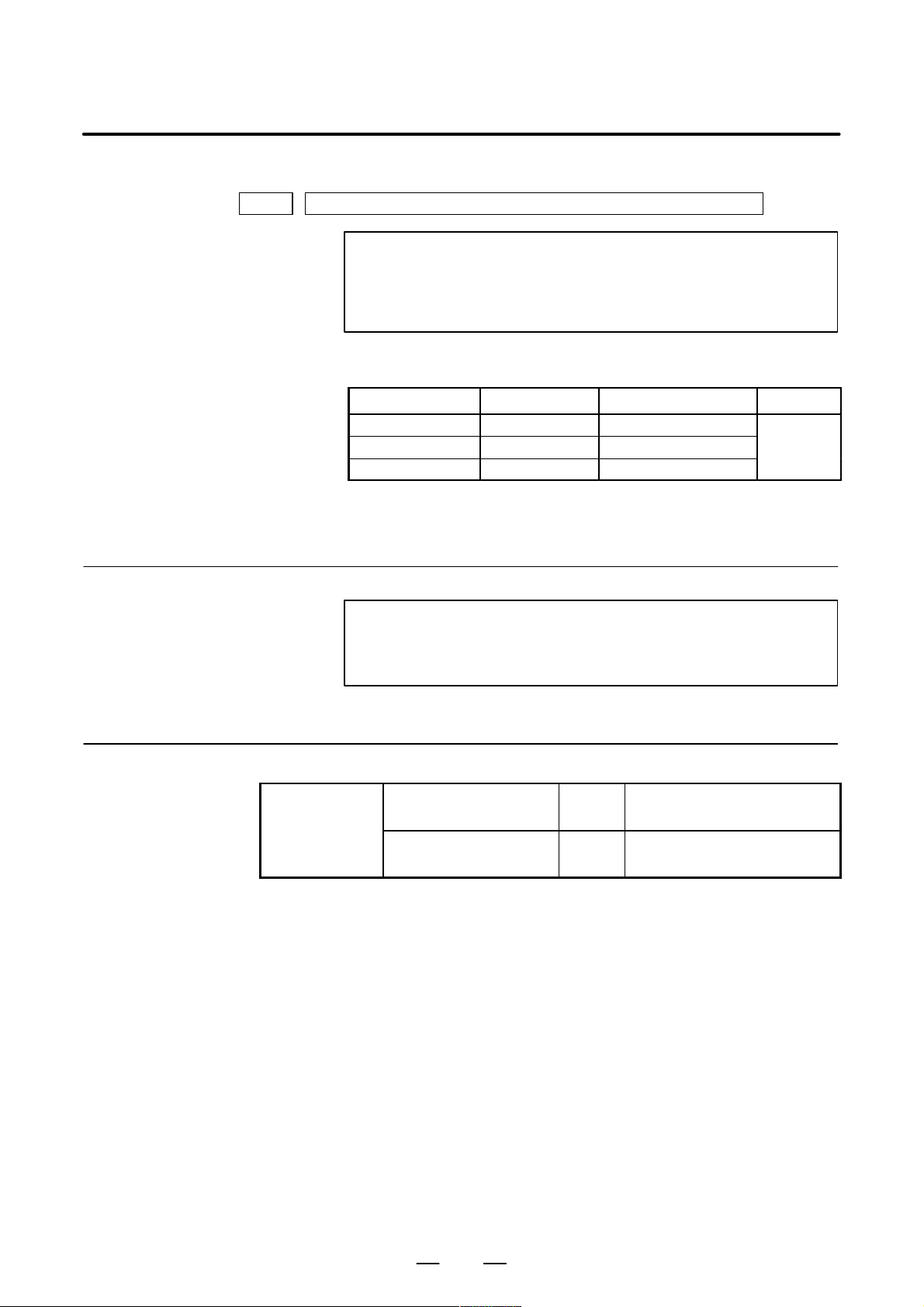
Applicable models
Signal description
The models covered by this manual, and their abbreviations are :
Model name Abbreviation
FANUC Series 0i–TB 0i–TB
Series 0i–B 0i
FANUC Series 0i–MB 0i–MB
FANUC Series 0i Mate–TB 0i Mate–TB
Series 0i Mate–B 0i Mate
FANUC Series 0i Mate–MB 0i Mate–MB
NOTE
Some functions described in this manual may not be applied
to some products.
For details, refer to the DESCRIPTIONS manual
(B–63832EN).
Relation of interface signals among the CNC, the PMC and the machine
tool is shown below:
D Expression of signals
G000–
CNC PMC
F000–
X000–
Y000–
Machine
tool
NOTE
For the signals, a single data number is assigned to 8 bits.
Each bit has a different meaning.
One address accommodates eight signals.
Symbol (#0 to #7 indicates bit position)Address
#7 #6 #5 #4 #3 #2 #1 #0
OPF000 SA STL SPL RWD
In an item where both T series and M series are described, some signals
are covered with shade ( ) in the signal address figure as shown
below. This means either T series or M series does not have this signal.
Upper part is for T series and lower part is for M series.
[Example 1]
Signal EXLM, ST is a common signal, STLK is for T series only and
RLSOT and RVS are for M series only.
G007
#7
#6
EXLM
p–2
#2
ST
#1
STLKRLSOT
#0
RVS
T series
M series
Page 8

B–63833EN–1/02
–128 to 127
In some parameters, signs are ig-
–32768 to 32767
–99999999 to
PREFACE
Parameter description
Parameters are classified by data type as follows :
Dta type Valid data range Remarks
Bit
0 or 1
Bit axis
Byte
Byte axis
Word
Word axis
2–word
2–word axis
–128 to 127 In some parameters, signs are ig-
0 to 255
–32768 to 32767
0 to 65535
–99999999 to
99999999
nored.
NOTE
1 For the bit type and bit axis type parameters, a single data
number is assigned to 8 bits. Each bit has a different
meaning.
2 The axis type allows data to be set separately for each
control axis.
3 The valid data range for each data type indicates a general
range. The range varies according to the parameters. For
the valid data range of a specific parameter, see the
explanation of the parameter.
p–3
Page 9

PREFACE
D Notation of bit type and
bit axis type parameters
0000 SEQ INI ISO TVC
D Notation of parameters
other than bit type and
bit axis type
1023 Servo axis number of a specific axis
B–63833EN–1/02
Data (#0 to #7 indicates bit position)Data No.
#7 #6 #5 #4 #3 #2 #1 #0
DataData No.
NOTE
In an item where both T series and M series are described,
parameters having different meanings between the T series
and M series and parameters that are valid only for the T or
M series are indicated in two levels as shown below.
Parameters left blank are unavaliable.
[Example 1]
5010
[Example 2]
3401
[Example 3]
1450
Parameter 5010 has different meanigs for the T series and M series.
T ool nose radius compensation . . .
Cutter compensation C . . .
T series
M series
DPI is a parameter common to the M and T series, but GSB and GSC
are parameters valid only for the T series.
#7
GSC
#6
GSB
#0
DPI
DPI
T series
M series
The following parameter is provided only for the M series.
T series
F1 digit feed . . .
M series
p–4
Page 10

B–63833EN–1/02
PREFACE
Related manuals of
Series 0i–B/0i Mate–B
The following table lists the manuals related to Series 0i–B and 0i
Mate–B. This manual is indicated by an asterisk(*).
Manual name
DESCRIPTIONS B–63832EN
CONNECTION MANUAL (HARDWARE) B–63833EN
CONNECTION MANUAL (FUNCTION) B–63833EN–1 *
Series 0i–TB OPERATOR’S MANUAL B–63834EN
Series 0i–MB OPERA T OR’S MANUAL B–63844EN
Series 0i Mate–TB OPERATOR’S MANUAL B–63854EN
Series 0i Mate–MB OPERA T OR’S MANUAL B–63864EN
MAINTENANCE MANUAL B–63835EN
P ARAMETER MANUAL B–63840EN
Programming
Macro Compiler/Macro Executor
PROGRAMMING MANUAL
FANUC MACRO COMPILER
(For Personal Computer)PROGRAMMING MANUAL
Specification
number
B–61803E–1
B–66102E
PMC
PMC Ladder Language PROGRAMMING MANUAL B–61863E
PMC C Language PROGRAMMING MANUAL B–61863E–1
Network
PROFIBUS–DP Board OPERA T OR’S MANUAL B–62924EN
Ethernet Board/DA T A SERVER Board
OPERA T OR’S MANUAL
FAST Ethernet Board/FAST DAT A SER VER
OPERA T OR’S MANUAL
DeviceNet Board OPERA T OR’S MANUAL B–63404EN
OPEN CNC
FANUC OPEN CNC OPERATOR’S MANUAL
Basic Operation Package 1 (For Windows 95/NT)
FANUC OPEN CNC OPERATOR’S MANUAL
(DNC Operation Management Package)
B–63354EN
B–63644EN
B–62994EN
B–63214EN
p–5
Page 11

PREFACE
B–63833EN–1/02
Related manuals of
Servo Motor ai series
The following table lists the manuals related to Servo Motor ai series
Manual name
FANUC AC SER VO MOTOR ai series DESCRIPTIONS B–65262EN
FANUC AC SER VO MOTOR ai series
P ARAMETER MANUAL
FANUC AC SPINDLE MOT OR ai series
DESCRIPTIONS
FANUC AC SPINDLE MOT OR ai series
P ARAMETER MANUAL
FANUC SER VO AMPLIFIER ai series DESCRIPTIONS B–65282EN
FANUC SER VO MOT OR ai series
MAINTENANCE MANUAL
Specification
number
B–65270EN
B–65272EN
B–65280EN
B–65285EN
Either of the following servo motors and the corresponding spindle can
be connected to the CNC covered in this manual.
D FANUC SERVO MOTOR αi series
This manual mainly assumes that the FANUC SER VO MOT OR αi series
of servo motor is used. For servo motor and spindle information, refer to
the manuals for the servo motor and spindle that are actually connected.
Related manuals of
Servo Motor b series
The following table lists the manuals related to Servo Motor b series
Manual name
FANUC SER VO MOT OR b series DESCRIPTIONS B–65232EN
FANUC SER VO MOT OR b series
MAINTENANCE MANUAL
FANUC SER VO MOT OR b series (I/O Link Option)
DESCRIPTIONS
Specification
number
B–65235EN
B–65245EN
p–6
Page 12

B–63833EN–1/02
Table of Contents
Volume 1
DEFINITION OF WARNING, CAUTION, AND NOTE s–1. . . . . . . . . . . . . . . . . . . . . . . . . . . . .
PREFACE p–1. . . . . . . . . . . . . . . . . . . . . . . . . . . . . . . . . . . . . . . . . . . . . . . . . . . . . . . . . . . . . . . . . . .
1. AXIS CONTROL 1. . . . . . . . . . . . . . . . . . . . . . . . . . . . . . . . . . . . . . . . . . . . . . . . . . . . . . . . . . . . . .
1.1 CONTROLLED AXES 2. . . . . . . . . . . . . . . . . . . . . . . . . . . . . . . . . . . . . . . . . . . . . . . . . . . . . . . . . . . . .
1.2 SETTING EACH AXIS 4. . . . . . . . . . . . . . . . . . . . . . . . . . . . . . . . . . . . . . . . . . . . . . . . . . . . . . . . . . . . .
1.2.1 Name of Axes 4. . . . . . . . . . . . . . . . . . . . . . . . . . . . . . . . . . . . . . . . . . . . . . . . . . . . . . . . . . . . . . . .
1.2.2 Increment System 6. . . . . . . . . . . . . . . . . . . . . . . . . . . . . . . . . . . . . . . . . . . . . . . . . . . . . . . . . . . . .
1.2.3 Specifying the Rotation Axis 9. . . . . . . . . . . . . . . . . . . . . . . . . . . . . . . . . . . . . . . . . . . . . . . . . . . .
1.2.4 Outputting the Movement State of an Axis 12. . . . . . . . . . . . . . . . . . . . . . . . . . . . . . . . . . . . . . . .
1.2.5 Mirror Image 14. . . . . . . . . . . . . . . . . . . . . . . . . . . . . . . . . . . . . . . . . . . . . . . . . . . . . . . . . . . . . . . .
1.2.6 Follow–up 17. . . . . . . . . . . . . . . . . . . . . . . . . . . . . . . . . . . . . . . . . . . . . . . . . . . . . . . . . . . . . . . . . .
1.2.7 Servo Off (Mechanical Handle) 19. . . . . . . . . . . . . . . . . . . . . . . . . . . . . . . . . . . . . . . . . . . . . . . . .
1.2.8 Position Switch 21. . . . . . . . . . . . . . . . . . . . . . . . . . . . . . . . . . . . . . . . . . . . . . . . . . . . . . . . . . . . . .
1.3 ERROR COMPENSATION 26. . . . . . . . . . . . . . . . . . . . . . . . . . . . . . . . . . . . . . . . . . . . . . . . . . . . . . . . .
1.3.1 Stored Pitch Error Compensation 26. . . . . . . . . . . . . . . . . . . . . . . . . . . . . . . . . . . . . . . . . . . . . . . .
1.3.2 Backlash Compensation 36. . . . . . . . . . . . . . . . . . . . . . . . . . . . . . . . . . . . . . . . . . . . . . . . . . . . . . .
1.4 SETTINGS RELATED TO SERVO–CONTROLLED AXES 38. . . . . . . . . . . . . . . . . . . . . . . . . . . . . .
1.4.1 Parameters Related to Servo 38. . . . . . . . . . . . . . . . . . . . . . . . . . . . . . . . . . . . . . . . . . . . . . . . . . . .
1.4.2 Absolute Position Detection 43. . . . . . . . . . . . . . . . . . . . . . . . . . . . . . . . . . . . . . . . . . . . . . . . . . . .
1.4.3 FSSB Setting 45. . . . . . . . . . . . . . . . . . . . . . . . . . . . . . . . . . . . . . . . . . . . . . . . . . . . . . . . . . . . . . . .
1.5 SETTINGS RELATED WITH COORDINATE SYSTEMS 64. . . . . . . . . . . . . . . . . . . . . . . . . . . . . . . .
1.5.1 Machine Coordinate System 64. . . . . . . . . . . . . . . . . . . . . . . . . . . . . . . . . . . . . . . . . . . . . . . . . . . .
1.5.2 Workpiece Coordinate System/Addition of Workpiece Coordinate System Pair 66. . . . . . . . . . .
1.5.3 Rotary Axis Roll Over 71. . . . . . . . . . . . . . . . . . . . . . . . . . . . . . . . . . . . . . . . . . . . . . . . . . . . . . . .
1.6 SIMPLE SYNCHRONOUS CONTROL 74. . . . . . . . . . . . . . . . . . . . . . . . . . . . . . . . . . . . . . . . . . . . . . .
1.7 ANGULAR AXIS CONTROL 90. . . . . . . . . . . . . . . . . . . . . . . . . . . . . . . . . . . . . . . . . . . . . . . . . . . . . .
2. PREPARATIONS FOR OPERATION 93. . . . . . . . . . . . . . . . . . . . . . . . . . . . . . . . . . . . . . . . . .
2.1 EMERGENCY STOP 94. . . . . . . . . . . . . . . . . . . . . . . . . . . . . . . . . . . . . . . . . . . . . . . . . . . . . . . . . . . . .
2.2 CNC READY SIGNAL 97. . . . . . . . . . . . . . . . . . . . . . . . . . . . . . . . . . . . . . . . . . . . . . . . . . . . . . . . . . . .
2.3 OVERTRAVEL CHECK 99. . . . . . . . . . . . . . . . . . . . . . . . . . . . . . . . . . . . . . . . . . . . . . . . . . . . . . . . . . .
2.3.1 Overtravel Signal 99. . . . . . . . . . . . . . . . . . . . . . . . . . . . . . . . . . . . . . . . . . . . . . . . . . . . . . . . . . . .
2.3.2 Stored Stroke Check 1 102. . . . . . . . . . . . . . . . . . . . . . . . . . . . . . . . . . . . . . . . . . . . . . . . . . . . . . . .
2.3.3 Stored Stroke Check 2, 3 109. . . . . . . . . . . . . . . . . . . . . . . . . . . . . . . . . . . . . . . . . . . . . . . . . . . . .
2.3.4 Chuck/Tailstock Barrier (T series) 117. . . . . . . . . . . . . . . . . . . . . . . . . . . . . . . . . . . . . . . . . . . . . .
2.4 ALARM SIGNAL 123. . . . . . . . . . . . . . . . . . . . . . . . . . . . . . . . . . . . . . . . . . . . . . . . . . . . . . . . . . . . . . .
2.5 START LOCK/INTERLOCK 125. . . . . . . . . . . . . . . . . . . . . . . . . . . . . . . . . . . . . . . . . . . . . . . . . . . . . .
2.6 MODE SELECTION 131. . . . . . . . . . . . . . . . . . . . . . . . . . . . . . . . . . . . . . . . . . . . . . . . . . . . . . . . . . . . .
2.7 STATUS OUTPUT SIGNAL 139. . . . . . . . . . . . . . . . . . . . . . . . . . . . . . . . . . . . . . . . . . . . . . . . . . . . . . .
2.8 VRDY OFF ALARM IGNORE SIGNAL 141. . . . . . . . . . . . . . . . . . . . . . . . . . . . . . . . . . . . . . . . . . . . .
2.9 ABNORMAL LOAD DETECTION 143. . . . . . . . . . . . . . . . . . . . . . . . . . . . . . . . . . . . . . . . . . . . . . . . .
c–1
Page 13

TABLE OF CONTENTS
2.10 SERVO/SPINDLE MOTOR SPEED DETECTION 154. . . . . . . . . . . . . . . . . . . . . . . . . . . . . . . . . . . . .
B–63833EN–1/02
3. MANUAL OPERATION 159. . . . . . . . . . . . . . . . . . . . . . . . . . . . . . . . . . . . . . . . . . . . . . . . . . . . .
3.1 JOG FEED/INCREMENTAL FEED 160. . . . . . . . . . . . . . . . . . . . . . . . . . . . . . . . . . . . . . . . . . . . . . . . .
3.2 MANUAL HANDLE FEED 168. . . . . . . . . . . . . . . . . . . . . . . . . . . . . . . . . . . . . . . . . . . . . . . . . . . . . . .
3.3 MANUAL HANDLE INTERRUPTION 173. . . . . . . . . . . . . . . . . . . . . . . . . . . . . . . . . . . . . . . . . . . . . .
4. REFERENCE POSITION ESTABLISHMENT 175. . . . . . . . . . . . . . . . . . . . . . . . . . . . . . . . . .
4.1 MANUAL REFERENCE POSITION RETURN 176. . . . . . . . . . . . . . . . . . . . . . . . . . . . . . . . . . . . . . .
4.2 SETTING THE REFERENCE POSITION WITHOUT DOGS 188. . . . . . . . . . . . . . . . . . . . . . . . . . . .
4.3 REFERENCE POSITION SHIFT 195. . . . . . . . . . . . . . . . . . . . . . . . . . . . . . . . . . . . . . . . . . . . . . . . . . .
4.4 REFERENCE POSITION RETURN 198. . . . . . . . . . . . . . . . . . . . . . . . . . . . . . . . . . . . . . . . . . . . . . . . .
4.5 2ND REFERENCE POSITION RETURN/3RD, 4TH REFERENCE POSITION RETURN 200. . . . .
4.6 BUTT–TYPE REFERENCE POSITION SETTING 203. . . . . . . . . . . . . . . . . . . . . . . . . . . . . . . . . . . . .
5. AUTOMATIC OPERATION 210. . . . . . . . . . . . . . . . . . . . . . . . . . . . . . . . . . . . . . . . . . . . . . . . . .
5.1 CYCLE START/FEED HOLD 211. . . . . . . . . . . . . . . . . . . . . . . . . . . . . . . . . . . . . . . . . . . . . . . . . . . . .
5.2 RESET AND REWIND 216. . . . . . . . . . . . . . . . . . . . . . . . . . . . . . . . . . . . . . . . . . . . . . . . . . . . . . . . . . .
5.3 TESTING A PROGRAM 221. . . . . . . . . . . . . . . . . . . . . . . . . . . . . . . . . . . . . . . . . . . . . . . . . . . . . . . . . .
5.3.1 Machine Lock 221. . . . . . . . . . . . . . . . . . . . . . . . . . . . . . . . . . . . . . . . . . . . . . . . . . . . . . . . . . . . . .
5.3.2 Dry Run 224. . . . . . . . . . . . . . . . . . . . . . . . . . . . . . . . . . . . . . . . . . . . . . . . . . . . . . . . . . . . . . . . . . .
5.3.3 Single Block 227. . . . . . . . . . . . . . . . . . . . . . . . . . . . . . . . . . . . . . . . . . . . . . . . . . . . . . . . . . . . . . .
5.4 MANUAL ABSOLUTE ON/OFF 230. . . . . . . . . . . . . . . . . . . . . . . . . . . . . . . . . . . . . . . . . . . . . . . . . . .
5.5 OPTIONAL BLOCK SKIP/ADDITION OF OPTIONAL BLOCK SKIP 233. . . . . . . . . . . . . . . . . . . .
5.6 SEQUENCE NUMBER COMPARISON AND STOP 237. . . . . . . . . . . . . . . . . . . . . . . . . . . . . . . . . . .
5.7 PROGRAM RESTART 238. . . . . . . . . . . . . . . . . . . . . . . . . . . . . . . . . . . . . . . . . . . . . . . . . . . . . . . . . . .
5.8 EXACT STOP/EXACT STOP MODE/TAPPING MODE/CUTTING MODE (M SERIES) 241. . . . . .
5.9 DNC OPERATION 243. . . . . . . . . . . . . . . . . . . . . . . . . . . . . . . . . . . . . . . . . . . . . . . . . . . . . . . . . . . . . .
5.10 MANUAL INTERVENTION AND RETURN 246. . . . . . . . . . . . . . . . . . . . . . . . . . . . . . . . . . . . . . . . .
5.11 RETRACTION FOR RIGID TAPPING (M SERIES) 247. . . . . . . . . . . . . . . . . . . . . . . . . . . . . . . . . . . .
6. INTERPOLATION FUNCTION 254. . . . . . . . . . . . . . . . . . . . . . . . . . . . . . . . . . . . . . . . . . . . . . .
6.1 POSITIONING 255. . . . . . . . . . . . . . . . . . . . . . . . . . . . . . . . . . . . . . . . . . . . . . . . . . . . . . . . . . . . . . . . . .
6.2 LINEAR INTERPOLATION 257. . . . . . . . . . . . . . . . . . . . . . . . . . . . . . . . . . . . . . . . . . . . . . . . . . . . . . .
6.3 CIRCULAR INTERPOLATION 260. . . . . . . . . . . . . . . . . . . . . . . . . . . . . . . . . . . . . . . . . . . . . . . . . . . .
6.4 THREAD CUTTING 266. . . . . . . . . . . . . . . . . . . . . . . . . . . . . . . . . . . . . . . . . . . . . . . . . . . . . . . . . . . . .
6.4.1 Thread Cutting 266. . . . . . . . . . . . . . . . . . . . . . . . . . . . . . . . . . . . . . . . . . . . . . . . . . . . . . . . . . . . .
6.4.2 Thread Cutting Cycle Retract (T series) 273. . . . . . . . . . . . . . . . . . . . . . . . . . . . . . . . . . . . . . . . . .
6.5 SINGLE DIRECTION POSITIONING 275. . . . . . . . . . . . . . . . . . . . . . . . . . . . . . . . . . . . . . . . . . . . . . .
6.6 HELICAL INTERPOLATION 282. . . . . . . . . . . . . . . . . . . . . . . . . . . . . . . . . . . . . . . . . . . . . . . . . . . . . .
6.7 POLAR COORDINATE INTERPOLATION 284. . . . . . . . . . . . . . . . . . . . . . . . . . . . . . . . . . . . . . . . . .
6.8 CYLINDRICAL INTERPOLATION 287. . . . . . . . . . . . . . . . . . . . . . . . . . . . . . . . . . . . . . . . . . . . . . . . .
6.9 POLYGONAL TURNING (T SERIES) 290. . . . . . . . . . . . . . . . . . . . . . . . . . . . . . . . . . . . . . . . . . . . . . .
6.9.1 Polygonal Turning 291. . . . . . . . . . . . . . . . . . . . . . . . . . . . . . . . . . . . . . . . . . . . . . . . . . . . . . . . . . .
6.10 NORMAL DIRECTION CONTROL (M SERIES) 296. . . . . . . . . . . . . . . . . . . . . . . . . . . . . . . . . . . . . .
6.11 LINEAR INTERPOLATION (G28, G30, G53) 302. . . . . . . . . . . . . . . . . . . . . . . . . . . . . . . . . . . . . . . . .
c–2
Page 14

B–63833EN–1/02
TABLE OF CONTENTS
7. FEEDRATE CONTROL/ACCELERATION AND DECELERATION CONTROL 304. . . . .
7.1 FEEDRATE CONTROL 305. . . . . . . . . . . . . . . . . . . . . . . . . . . . . . . . . . . . . . . . . . . . . . . . . . . . . . . . . .
7.1.1 Rapid Traverse Rate 305. . . . . . . . . . . . . . . . . . . . . . . . . . . . . . . . . . . . . . . . . . . . . . . . . . . . . . . . .
7.1.2 Cutting Feedrate Clamp 308. . . . . . . . . . . . . . . . . . . . . . . . . . . . . . . . . . . . . . . . . . . . . . . . . . . . . .
7.1.3 Feed Per Minute 310. . . . . . . . . . . . . . . . . . . . . . . . . . . . . . . . . . . . . . . . . . . . . . . . . . . . . . . . . . . .
7.1.4 Feed Per Revolution/Manual Feed Per Revolution 313. . . . . . . . . . . . . . . . . . . . . . . . . . . . . . . . .
7.1.5 F1-digit Feed (M series) 315. . . . . . . . . . . . . . . . . . . . . . . . . . . . . . . . . . . . . . . . . . . . . . . . . . . . . .
7.1.6 Override 318. . . . . . . . . . . . . . . . . . . . . . . . . . . . . . . . . . . . . . . . . . . . . . . . . . . . . . . . . . . . . . . . . . .
7.1.6.1 Rapid traverse override 318. . . . . . . . . . . . . . . . . . . . . . . . . . . . . . . . . . . . . . . . . . . . . . . . . . . . . . .
7.1.6.2 Feedrate override 321. . . . . . . . . . . . . . . . . . . . . . . . . . . . . . . . . . . . . . . . . . . . . . . . . . . . . . . . . . . .
7.1.6.3 Override cancel 323. . . . . . . . . . . . . . . . . . . . . . . . . . . . . . . . . . . . . . . . . . . . . . . . . . . . . . . . . . . . .
7.1.7 Automatic Corner Override (M series) 324. . . . . . . . . . . . . . . . . . . . . . . . . . . . . . . . . . . . . . . . . . .
7.1.8 External Deceleration 328. . . . . . . . . . . . . . . . . . . . . . . . . . . . . . . . . . . . . . . . . . . . . . . . . . . . . . . .
7.1.9 Feedrate Clamping by Arc Radius (M series) 330. . . . . . . . . . . . . . . . . . . . . . . . . . . . . . . . . . . . .
7.1.10 Automatic Corner Deceleration 333. . . . . . . . . . . . . . . . . . . . . . . . . . . . . . . . . . . . . . . . . . . . . . . .
7.1.11 Advanced Preview Control 341. . . . . . . . . . . . . . . . . . . . . . . . . . . . . . . . . . . . . . . . . . . . . . . . . . . .
7.1.12 AI Advanced Control (M Series) 352. . . . . . . . . . . . . . . . . . . . . . . . . . . . . . . . . . . . . . . . . . . . . . .
7.2 ACCELERATION/DECELERATION CONTROL 381. . . . . . . . . . . . . . . . . . . . . . . . . . . . . . . . . . . . . .
7.2.1 Automatic Acceleration/Deceleration 381. . . . . . . . . . . . . . . . . . . . . . . . . . . . . . . . . . . . . . . . . . .
7.2.1.1 Automatic acceleration/deceleration 381. . . . . . . . . . . . . . . . . . . . . . . . . . . . . . . . . . . . . . . . . . . .
7.2.1.2 Rapid traverse block overlap 385. . . . . . . . . . . . . . . . . . . . . . . . . . . . . . . . . . . . . . . . . . . . . . . . . .
7.2.2 Rapid Traverse Bell–shaped Acceleration/Deceleration 387. . . . . . . . . . . . . . . . . . . . . . . . . . . . .
7.2.3 Linear Acceleration/Deceleration after Cutting Feed Interpolation 390. . . . . . . . . . . . . . . . . . . .
7.2.4 Corner Control 393. . . . . . . . . . . . . . . . . . . . . . . . . . . . . . . . . . . . . . . . . . . . . . . . . . . . . . . . . . . . .
7.2.4.1 In–position check 393. . . . . . . . . . . . . . . . . . . . . . . . . . . . . . . . . . . . . . . . . . . . . . . . . . . . . . . . . . .
7.2.4.2 In–position check independently of feed/rapid traverse 395. . . . . . . . . . . . . . . . . . . . . . . . . . . . . .
7.2.4.3 Error detect (T series) 397. . . . . . . . . . . . . . . . . . . . . . . . . . . . . . . . . . . . . . . . . . . . . . . . . . . . . . . .
7.2.5 Feed Forward in Rapid Traverse 399. . . . . . . . . . . . . . . . . . . . . . . . . . . . . . . . . . . . . . . . . . . . . . . .
8. AUXILIARY FUNCTION 400. . . . . . . . . . . . . . . . . . . . . . . . . . . . . . . . . . . . . . . . . . . . . . . . . . . .
8.1 MISCELLANEOUS FUNCTION/2ND AUXILIARY FUNCTION 401. . . . . . . . . . . . . . . . . . . . . . . . .
8.2 AUXILIARY FUNCTION LOCK 413. . . . . . . . . . . . . . . . . . . . . . . . . . . . . . . . . . . . . . . . . . . . . . . . . . .
8.3 MULTIPLE M COMMANDS IN A SINGLE BLOCK 415. . . . . . . . . . . . . . . . . . . . . . . . . . . . . . . . . . .
8.4 HIGH–SPEED M/S/T/B INTERFACE 419. . . . . . . . . . . . . . . . . . . . . . . . . . . . . . . . . . . . . . . . . . . . . . .
9. SPINDLE SPEED FUNCTION 423. . . . . . . . . . . . . . . . . . . . . . . . . . . . . . . . . . . . . . . . . . . . . . .
9.1 SPINDLE SPEED FUNCTION (S CODE OUTPUT) 424. . . . . . . . . . . . . . . . . . . . . . . . . . . . . . . . . . . .
9.2 SPINDLE SERIAL OUTPUT/SPINDLE ANALOG OUTPUT 425. . . . . . . . . . . . . . . . . . . . . . . . . . . .
9.3 SPINDLE SPEED CONTROL 433. . . . . . . . . . . . . . . . . . . . . . . . . . . . . . . . . . . . . . . . . . . . . . . . . . . . .
9.4 CONSTANT SURFACE SPEED CONTROL 462. . . . . . . . . . . . . . . . . . . . . . . . . . . . . . . . . . . . . . . . . .
9.5 SPINDLE SPEED FLUCTUATION DETECTION 468. . . . . . . . . . . . . . . . . . . . . . . . . . . . . . . . . . . . .
9.6 ACTUAL SPINDLE SPEED OUTPUT (T SERIES) 473. . . . . . . . . . . . . . . . . . . . . . . . . . . . . . . . . . . .
9.7 SPINDLE POSITIONING (T SERIES) 474. . . . . . . . . . . . . . . . . . . . . . . . . . . . . . . . . . . . . . . . . . . . . . .
9.8 Cs CONTOUR CONTROL 495. . . . . . . . . . . . . . . . . . . . . . . . . . . . . . . . . . . . . . . . . . . . . . . . . . . . . . . .
9.9 MULTI–SPINDLE CONTROL 511. . . . . . . . . . . . . . . . . . . . . . . . . . . . . . . . . . . . . . . . . . . . . . . . . . . . .
9.10 RIGID TAPPING 525. . . . . . . . . . . . . . . . . . . . . . . . . . . . . . . . . . . . . . . . . . . . . . . . . . . . . . . . . . . . . . . .
c–3
Page 15

TABLE OF CONTENTS
9.10.1 General 525. . . . . . . . . . . . . . . . . . . . . . . . . . . . . . . . . . . . . . . . . . . . . . . . . . . . . . . . . . . . . . . . . . .
9.10.2 Connection Among Spindle, Spindle Motor, and Position Coder 527. . . . . . . . . . . . . . . . . . . . . .
9.10.3 Rigid Tapping Specification 532. . . . . . . . . . . . . . . . . . . . . . . . . . . . . . . . . . . . . . . . . . . . . . . . . . .
9.10.4 Display Data on the Diagnosis Screen 533. . . . . . . . . . . . . . . . . . . . . . . . . . . . . . . . . . . . . . . . . . .
9.10.5 Command Format 537. . . . . . . . . . . . . . . . . . . . . . . . . . . . . . . . . . . . . . . . . . . . . . . . . . . . . . . . . . .
9.10.6 Signal 541. . . . . . . . . . . . . . . . . . . . . . . . . . . . . . . . . . . . . . . . . . . . . . . . . . . . . . . . . . . . . . . . . . . . .
9.10.6.1 Signals for the rigid tapping function 541. . . . . . . . . . . . . . . . . . . . . . . . . . . . . . . . . . . . . . . . . . . .
9.10.6.2 Signals related to S code output 542. . . . . . . . . . . . . . . . . . . . . . . . . . . . . . . . . . . . . . . . . . . . . . . .
9.10.6.3 Signals related to gear switching 543. . . . . . . . . . . . . . . . . . . . . . . . . . . . . . . . . . . . . . . . . . . . . . .
9.10.6.4 Signals related to second spindle rigid tapping 545. . . . . . . . . . . . . . . . . . . . . . . . . . . . . . . . . . . .
9.10.6.5 Signal addresses 547. . . . . . . . . . . . . . . . . . . . . . . . . . . . . . . . . . . . . . . . . . . . . . . . . . . . . . . . . . . .
9.10.6.6 Notes on interface with the PMC 547. . . . . . . . . . . . . . . . . . . . . . . . . . . . . . . . . . . . . . . . . . . . . . .
9.10.7 Timing Charts for Rigid Tapping Specification 550. . . . . . . . . . . . . . . . . . . . . . . . . . . . . . . . . . . .
9.10.7.1 When M29 is specified before G84 (G74) 551. . . . . . . . . . . . . . . . . . . . . . . . . . . . . . . . . . . . . . . .
9.10.7.2 M29 and G84 (G74) are specified in the same block 555. . . . . . . . . . . . . . . . . . . . . . . . . . . . . . . .
9.10.7.3 Specifying G84 (G74) for rigid tapping by parameters 559. . . . . . . . . . . . . . . . . . . . . . . . . . . . . .
9.10.7.4 Timing to cancel rigid tapping mode 563. . . . . . . . . . . . . . . . . . . . . . . . . . . . . . . . . . . . . . . . . . . .
9.10.8 Parameter 565. . . . . . . . . . . . . . . . . . . . . . . . . . . . . . . . . . . . . . . . . . . . . . . . . . . . . . . . . . . . . . . . . .
9.10.9 Alarm and Message 588. . . . . . . . . . . . . . . . . . . . . . . . . . . . . . . . . . . . . . . . . . . . . . . . . . . . . . . . . .
9.10.10 Notes 589. . . . . . . . . . . . . . . . . . . . . . . . . . . . . . . . . . . . . . . . . . . . . . . . . . . . . . . . . . . . . . . . . . . . .
9.11 SPINDLE SYNCHRONOUS CONTROL 594. . . . . . . . . . . . . . . . . . . . . . . . . . . . . . . . . . . . . . . . . . . . .
9.12 SPINDLE ORIENTATION 598. . . . . . . . . . . . . . . . . . . . . . . . . . . . . . . . . . . . . . . . . . . . . . . . . . . . . . . .
9.13 SPINDLE OUTPUT SWITCHING 601. . . . . . . . . . . . . . . . . . . . . . . . . . . . . . . . . . . . . . . . . . . . . . . . . .
B–63833EN–1/02
Volume 2
10. TOOL FUNCTIONS 603. . . . . . . . . . . . . . . . . . . . . . . . . . . . . . . . . . . . . . . . . . . . . . . . . . . . . . .
10.1 TOOL FUNCTION 604. . . . . . . . . . . . . . . . . . . . . . . . . . . . . . . . . . . . . . . . . . . . . . . . . . . . . . . . . . . . . .
10.2 TOOL COMPENSATION VALUE/T OOL COMPENSATION NUMBER/
TOOL COMPENSATION MEMORY 607. . . . . . . . . . . . . . . . . . . . . . . . . . . . . . . . . . . . . . . . . . . . . . . .
10.2.1 Tool Compensation Value/Tool Compensation Number/Tool Compensation Memory 607. . . . . .
10.3 TOOL LIFE MANAGEMENT 614. . . . . . . . . . . . . . . . . . . . . . . . . . . . . . . . . . . . . . . . . . . . . . . . . . . . .
10.3.1 Tool life management 614. . . . . . . . . . . . . . . . . . . . . . . . . . . . . . . . . . . . . . . . . . . . . . . . . . . . . . . .
10.3.2 Tool Life Arrival Notice Signal (M Series) 623. . . . . . . . . . . . . . . . . . . . . . . . . . . . . . . . . . . . . . .
10.4 CUTTER COMPENSATION 624. . . . . . . . . . . . . . . . . . . . . . . . . . . . . . . . . . . . . . . . . . . . . . . . . . . . . . .
10.4.1 Cutter Compensation C (M Series) 624. . . . . . . . . . . . . . . . . . . . . . . . . . . . . . . . . . . . . . . . . . . . . .
10.4.2 Tool Nose Radius Compensation (T Series) 629. . . . . . . . . . . . . . . . . . . . . . . . . . . . . . . . . . . . . . .
11. PROGRAM COMMAND 633. . . . . . . . . . . . . . . . . . . . . . . . . . . . . . . . . . . . . . . . . . . . . . . . . . .
11.1 DECIMAL POINT PROGRAMMING/
POCKET CALCULATOR TYPE DECIMAL POINT PROGRAMMING 634. . . . . . . . . . . . . . . . . . . .
11.2 G CODE SYSTEM (T SERIES) 636. . . . . . . . . . . . . . . . . . . . . . . . . . . . . . . . . . . . . . . . . . . . . . . . . . . .
11.3 PROGRAM CONFIGURATION 642. . . . . . . . . . . . . . . . . . . . . . . . . . . . . . . . . . . . . . . . . . . . . . . . . . . .
11.4 INCH/METRIC CONVERSION 645. . . . . . . . . . . . . . . . . . . . . . . . . . . . . . . . . . . . . . . . . . . . . . . . . . . .
11.5 CUSTOM MACRO 649. . . . . . . . . . . . . . . . . . . . . . . . . . . . . . . . . . . . . . . . . . . . . . . . . . . . . . . . . . . . . .
c–4
Page 16

B–63833EN–1/02
11.5.1 Custom Macro 649. . . . . . . . . . . . . . . . . . . . . . . . . . . . . . . . . . . . . . . . . . . . . . . . . . . . . . . . . . . . . .
11.5.2 Interruption Type Custom Macro 659. . . . . . . . . . . . . . . . . . . . . . . . . . . . . . . . . . . . . . . . . . . . . . .
11.6 CANNED CYCLE (M SERIES)/CANNED CYCLE FOR DRILLING (T SERIES) 663. . . . . . . . . . .
11.7 EXTERNAL MOTION FUNCTION (M SERIES) 674. . . . . . . . . . . . . . . . . . . . . . . . . . . . . . . . . . . . . .
11.8 CANNED CYCLE (T SERIES)/MULTIPLE REPETITIVE CANNED CYCLE (T SERIES) 676. . . .
11.9 INDEX TABLE INDEXING FUNCTION (M SERIES) 684. . . . . . . . . . . . . . . . . . . . . . . . . . . . . . . . . .
11.10 SCALING (M SERIES) 693. . . . . . . . . . . . . . . . . . . . . . . . . . . . . . . . . . . . . . . . . . . . . . . . . . . . . . . . . . .
11.11 COORDINATE SYSTEM ROTATION 697. . . . . . . . . . . . . . . . . . . . . . . . . . . . . . . . . . . . . . . . . . . . . . .
11.12 MACRO COMPILER/ EXECUTER 700. . . . . . . . . . . . . . . . . . . . . . . . . . . . . . . . . . . . . . . . . . . . . . . . .
11.13 SMALL HOLE PECK DRILLING CYCLE (M SERIES) 701. . . . . . . . . . . . . . . . . . . . . . . . . . . . . . . .
TABLE OF CONTENTS
12. DISPLAY/SET/EDIT 708. . . . . . . . . . . . . . . . . . . . . . . . . . . . . . . . . . . . . . . . . . . . . . . . . . . . . . .
12.1 DISPLAY/SET 709. . . . . . . . . . . . . . . . . . . . . . . . . . . . . . . . . . . . . . . . . . . . . . . . . . . . . . . . . . . . . . . . . .
12.1.1 Clock Function 709. . . . . . . . . . . . . . . . . . . . . . . . . . . . . . . . . . . . . . . . . . . . . . . . . . . . . . . . . . . . .
12.1.2 Displaying Operation History 710. . . . . . . . . . . . . . . . . . . . . . . . . . . . . . . . . . . . . . . . . . . . . . . . . .
12.1.3 Help Function 715. . . . . . . . . . . . . . . . . . . . . . . . . . . . . . . . . . . . . . . . . . . . . . . . . . . . . . . . . . . . . .
12.1.4 Displaying Alarm History 716. . . . . . . . . . . . . . . . . . . . . . . . . . . . . . . . . . . . . . . . . . . . . . . . . . . . .
12.1.5 Servo Tuning Screen 717. . . . . . . . . . . . . . . . . . . . . . . . . . . . . . . . . . . . . . . . . . . . . . . . . . . . . . . . .
12.1.6 Spindle Setting and Tuning Screen 717. . . . . . . . . . . . . . . . . . . . . . . . . . . . . . . . . . . . . . . . . . . . . .
12.1.7 Waveform Diagnosis Display 718. . . . . . . . . . . . . . . . . . . . . . . . . . . . . . . . . . . . . . . . . . . . . . . . . .
12.1.8 Self–diagnosis 720. . . . . . . . . . . . . . . . . . . . . . . . . . . . . . . . . . . . . . . . . . . . . . . . . . . . . . . . . . . . . .
12.1.9 Display of Hardware and Software Configuration 721. . . . . . . . . . . . . . . . . . . . . . . . . . . . . . . . . .
12.1.10 Position Display Neglect 722. . . . . . . . . . . . . . . . . . . . . . . . . . . . . . . . . . . . . . . . . . . . . . . . . . . . . .
12.1.11 Run Hour and Parts Count Display 723. . . . . . . . . . . . . . . . . . . . . . . . . . . . . . . . . . . . . . . . . . . . . .
12.1.12 Graphic Display/Dynamic Graphic Display 729. . . . . . . . . . . . . . . . . . . . . . . . . . . . . . . . . . . . . . .
12.1.13 Displaying Operating Monitor 735. . . . . . . . . . . . . . . . . . . . . . . . . . . . . . . . . . . . . . . . . . . . . . . . .
12.1.14 Software Operator ’s Panel 737. . . . . . . . . . . . . . . . . . . . . . . . . . . . . . . . . . . . . . . . . . . . . . . . . . . .
12.1.15 Multi–language Display 747. . . . . . . . . . . . . . . . . . . . . . . . . . . . . . . . . . . . . . . . . . . . . . . . . . . . . .
12.1.16 Remote Diagnosis 748. . . . . . . . . . . . . . . . . . . . . . . . . . . . . . . . . . . . . . . . . . . . . . . . . . . . . . . . . . .
12.1.17 External Operator Message Logging and Display 750. . . . . . . . . . . . . . . . . . . . . . . . . . . . . . . . . .
12.1.18 Erase Screen Display/Automatic Erase Screen Display 751. . . . . . . . . . . . . . . . . . . . . . . . . . . . . .
12.1.19 Touch Panel 754. . . . . . . . . . . . . . . . . . . . . . . . . . . . . . . . . . . . . . . . . . . . . . . . . . . . . . . . . . . . . . . .
12.1.20 Periodic Maintenance Screen 758. . . . . . . . . . . . . . . . . . . . . . . . . . . . . . . . . . . . . . . . . . . . . . . . . .
12.1.21 Actual Speed Display 767. . . . . . . . . . . . . . . . . . . . . . . . . . . . . . . . . . . . . . . . . . . . . . . . . . . . . . . .
12.1.22 Other Functions 768. . . . . . . . . . . . . . . . . . . . . . . . . . . . . . . . . . . . . . . . . . . . . . . . . . . . . . . . . . . . .
12.2 EDIT 769. . . . . . . . . . . . . . . . . . . . . . . . . . . . . . . . . . . . . . . . . . . . . . . . . . . . . . . . . . . . . . . . . . . . . . . . . .
12.2.1 Part Program Storage Length 769. . . . . . . . . . . . . . . . . . . . . . . . . . . . . . . . . . . . . . . . . . . . . . . . . .
12.2.2 No. of Registered Programs 770. . . . . . . . . . . . . . . . . . . . . . . . . . . . . . . . . . . . . . . . . . . . . . . . . . .
12.2.3 Memory Protection Key 770. . . . . . . . . . . . . . . . . . . . . . . . . . . . . . . . . . . . . . . . . . . . . . . . . . . . . .
12.2.4 Password Function 772. . . . . . . . . . . . . . . . . . . . . . . . . . . . . . . . . . . . . . . . . . . . . . . . . . . . . . . . . .
12.2.5 Background Editing 774. . . . . . . . . . . . . . . . . . . . . . . . . . . . . . . . . . . . . . . . . . . . . . . . . . . . . . . . .
12.2.6 Playback 775. . . . . . . . . . . . . . . . . . . . . . . . . . . . . . . . . . . . . . . . . . . . . . . . . . . . . . . . . . . . . . . . . .
12.2.7 Conversational Programming with Graphic Function 776. . . . . . . . . . . . . . . . . . . . . . . . . . . . . . .
13. INPUT/OUTPUT OF DATA 777. . . . . . . . . . . . . . . . . . . . . . . . . . . . . . . . . . . . . . . . . . . . . . . . .
13.1 READER/PUNCHER INTERFACE 778. . . . . . . . . . . . . . . . . . . . . . . . . . . . . . . . . . . . . . . . . . . . . . . . .
13.2 DNC2 INTERFACE 789. . . . . . . . . . . . . . . . . . . . . . . . . . . . . . . . . . . . . . . . . . . . . . . . . . . . . . . . . . . . . .
c–5
Page 17

TABLE OF CONTENTS
13.3 EXTERNAL I/O DEVICE CONTROL 790. . . . . . . . . . . . . . . . . . . . . . . . . . . . . . . . . . . . . . . . . . . . . . .
13.4 EXTERNAL PROGRAM INPUT 797. . . . . . . . . . . . . . . . . . . . . . . . . . . . . . . . . . . . . . . . . . . . . . . . . . .
13.5 DATA INPUT/OUTPUT FUNCTIONS BASED ON THE I/O Link 802. . . . . . . . . . . . . . . . . . . . . . . .
B–63833EN–1/02
14. MEASUREMENT 827. . . . . . . . . . . . . . . . . . . . . . . . . . . . . . . . . . . . . . . . . . . . . . . . . . . . . . . . .
14.1 TOOL LENGTH MEASUREMENT (M SERIES) 828. . . . . . . . . . . . . . . . . . . . . . . . . . . . . . . . . . . . . .
14.2 AUTOMATIC TOOL LENGTH MEASUREMENT (M SERIES)/
AUTOMATIC TOOL OFFSET (T SERIES) 829. . . . . . . . . . . . . . . . . . . . . . . . . . . . . . . . . . . . . . . . . . .
14.3 SKIP FUNCTION 836. . . . . . . . . . . . . . . . . . . . . . . . . . . . . . . . . . . . . . . . . . . . . . . . . . . . . . . . . . . . . . .
14.3.1 Skip Function 836. . . . . . . . . . . . . . . . . . . . . . . . . . . . . . . . . . . . . . . . . . . . . . . . . . . . . . . . . . . . . .
14.3.2 High–speed Skip Signal 839. . . . . . . . . . . . . . . . . . . . . . . . . . . . . . . . . . . . . . . . . . . . . . . . . . . . . .
14.3.3 Multi–step Skip 842. . . . . . . . . . . . . . . . . . . . . . . . . . . . . . . . . . . . . . . . . . . . . . . . . . . . . . . . . . . . .
14.3.4 Torque Limit Skip 847. . . . . . . . . . . . . . . . . . . . . . . . . . . . . . . . . . . . . . . . . . . . . . . . . . . . . . . . . . .
14.4 ENTERING COMPENSATION VALUES 850. . . . . . . . . . . . . . . . . . . . . . . . . . . . . . . . . . . . . . . . . . . .
14.4.1 Input of Offset Value Measured A (T series) 850. . . . . . . . . . . . . . . . . . . . . . . . . . . . . . . . . . . . . .
14.4.2 Input of Tool Offset Value Measured B (T series) 852. . . . . . . . . . . . . . . . . . . . . . . . . . . . . . . . . .
14.4.3 Input of Measured Workpiece Origin Offsets 871. . . . . . . . . . . . . . . . . . . . . . . . . . . . . . . . . . . . . .
15. PMC CONTROL FUNCTION 872. . . . . . . . . . . . . . . . . . . . . . . . . . . . . . . . . . . . . . . . . . . . . . .
15.1 PMC AXIS CONTROL 873. . . . . . . . . . . . . . . . . . . . . . . . . . . . . . . . . . . . . . . . . . . . . . . . . . . . . . . . . . .
15.1.1 PMC Axis Control 873. . . . . . . . . . . . . . . . . . . . . . . . . . . . . . . . . . . . . . . . . . . . . . . . . . . . . . . . . . .
15.1.2 PMC Axis Control Expansion 920. . . . . . . . . . . . . . . . . . . . . . . . . . . . . . . . . . . . . . . . . . . . . . . . . .
15.2 EXTERNAL DATA INPUT 925. . . . . . . . . . . . . . . . . . . . . . . . . . . . . . . . . . . . . . . . . . . . . . . . . . . . . . . .
15.3 EXTERNAL WORKPIECE NUMBER SEARCH 937. . . . . . . . . . . . . . . . . . . . . . . . . . . . . . . . . . . . . .
15.3.1 External Workpiece Number Search 937. . . . . . . . . . . . . . . . . . . . . . . . . . . . . . . . . . . . . . . . . . . . .
15.3.2 Expanded External Workpiece Number Search 940. . . . . . . . . . . . . . . . . . . . . . . . . . . . . . . . . . . .
15.4 SPINDLE OUTPUT CONTROL BY THE PMC 942. . . . . . . . . . . . . . . . . . . . . . . . . . . . . . . . . . . . . . .
15.5 EXTERNAL KEY INPUT 949. . . . . . . . . . . . . . . . . . . . . . . . . . . . . . . . . . . . . . . . . . . . . . . . . . . . . . . . .
15.6 DIRECT OPERATION BY PMC OR OPEN CNC 955. . . . . . . . . . . . . . . . . . . . . . . . . . . . . . . . . . . . . .
15.6.1 DNC Operation by the PMC or OPEN CNC (PC with HSSB Connection) 955. . . . . . . . . . . . . . .
16. INTERFACE WITH THE POWER MATE CNC 956. . . . . . . . . . . . . . . . . . . . . . . . . . . . . . . .
16.1 FANUC SERVO MOTOR b SERIES I/O LINK OPTION
MANUAL HANDLE INTERFACE (PERIPHERAL DEVICE CONTROL) 957. . . . . . . . . . . . . . . . . .
17. PCMCIA ETHERNET FUNCTION 961. . . . . . . . . . . . . . . . . . . . . . . . . . . . . . . . . . . . . . . . . . .
17.1 PCMCIA ETHERNET 962. . . . . . . . . . . . . . . . . . . . . . . . . . . . . . . . . . . . . . . . . . . . . . . . . . . . . . . . . . . .
17.2 SETTING THE PCMCIA ETHERNET FUNCTION 963. . . . . . . . . . . . . . . . . . . . . . . . . . . . . . . . . . . .
17.2.1 Ethernet Parameter Setting Screen 963. . . . . . . . . . . . . . . . . . . . . . . . . . . . . . . . . . . . . . . . . . . . . .
17.2.2 Communication Parameter Input Method 966. . . . . . . . . . . . . . . . . . . . . . . . . . . . . . . . . . . . . . . .
17.3 PCMCIA ETHERNET ERROR MESSAGE SCREEN 968. . . . . . . . . . . . . . . . . . . . . . . . . . . . . . . . . . .
17.4 PCMCIA ETHERNET MAINTENANCE SCREEN 970. . . . . . . . . . . . . . . . . . . . . . . . . . . . . . . . . . . .
17.5 TROUBLESHOOTING 975. . . . . . . . . . . . . . . . . . . . . . . . . . . . . . . . . . . . . . . . . . . . . . . . . . . . . . . . . . .
17.5.1 Check Items Related to Connection 975. . . . . . . . . . . . . . . . . . . . . . . . . . . . . . . . . . . . . . . . . . . . .
17.5.2 Checking the Setting of Each Parameter 975. . . . . . . . . . . . . . . . . . . . . . . . . . . . . . . . . . . . . . . . .
17.5.3 Checking Communication 976. . . . . . . . . . . . . . . . . . . . . . . . . . . . . . . . . . . . . . . . . . . . . . . . . . . .
c–6
Page 18

B–63833EN–1/02
17.6 ERROR MESSAGES 979. . . . . . . . . . . . . . . . . . . . . . . . . . . . . . . . . . . . . . . . . . . . . . . . . . . . . . . . . . . . .
17.6.1 EMB_ETH MASTER CTRL LOG Screen 979. . . . . . . . . . . . . . . . . . . . . . . . . . . . . . . . . . . . . . . .
17.6.2 EMB_ETH FOCAS1/ETHER LOG Screen 980. . . . . . . . . . . . . . . . . . . . . . . . . . . . . . . . . . . . . . .
17.7 GLOSSARY FOR ETHERNET 981. . . . . . . . . . . . . . . . . . . . . . . . . . . . . . . . . . . . . . . . . . . . . . . . . . . . .
TABLE OF CONTENTS
APPENDIX
A. INTERFACE BETWEEN CNC AND PMC 985. . . . . . . . . . . . . . . . . . . . . . . . . . . . . . . . . . . . .
A.1 LIST OF ADDRESSES 986. . . . . . . . . . . . . . . . . . . . . . . . . . . . . . . . . . . . . . . . . . . . . . . . . . . . . . . . . . .
A.1.1 Series 0i/0i Mate Address List 986. . . . . . . . . . . . . . . . . . . . . . . . . . . . . . . . . . . . . . . . . . . . . . . . .
A.2 SIGNAL SUMMARY 1014. . . . . . . . . . . . . . . . . . . . . . . . . . . . . . . . . . . . . . . . . . . . . . . . . . . . . . . . . . .
A.2.1 Signal Summary (In Order of Functions) 1014. . . . . . . . . . . . . . . . . . . . . . . . . . . . . . . . . . . . . . . .
A.2.2 List of Signals (In Order of Symbols) 1030. . . . . . . . . . . . . . . . . . . . . . . . . . . . . . . . . . . . . . . . . . .
A.2.3 List of Signals (In Order of Addresses) 1045. . . . . . . . . . . . . . . . . . . . . . . . . . . . . . . . . . . . . . . . .
c–7
Page 19

Page 20

B–63833EN–1/02
1
1. AXIS CONTROL
AXIS CONTROL
1
Page 21

1. AXIS CONTROL
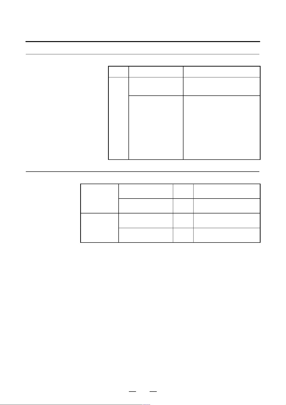
1.1
CONTROLLED AXES
General
B–63833EN–1/02
Series 0i–B
Series 0i Mate–B
Item M series T series
Controlled path 1 path 1 path
Controlled axes 4 axes 2 axes
Simultaneously
controlled axes
Axis control by PMC Max. simultaneous 4
Cs contouring control 1 axis 1 axis
Item M series T series
Controlled path 1 path 1 path
Controlled axes 3 axes 2 axes
Simultaneously
controlled axes
Axis control by PMC – –
Cs contouring control – –
Max. 4 axes Max. 4 axes
Max. simultaneous 4
axes (Not available on
Cs axis)
Max. 3 axes Max. 2 axes
axes (Not available on
Cs axis)
Parameter
1010 Number of CNC–controlled axes
NOTE
After setting this parameter, turn the power of f then on again
so that the setting will take effect.
[Data type] Byte
[Valid data range] 1, 2, 3, ..., the number of controlled axes
Set the maximum number of axes that can be controlled by the CNC.
[Example] Suppose that the first axis is the X axis, and the second and subsequent
axes are the Y, Z, and A axes in that order, and that they are controlled as
follows:
X, Y, and Z axes: Controlled by the CNC and PMC
A axis: Controlled by the PMC (cannot be controlled directly by the
CNC)
Then set this parameter to 3 (total 3: X, Y, and Z)
2
Page 22
B–63833EN–1/02
Alarm and message
1. AXIS CONTROL
Number Message Description
Reference item
Series 0i–B
Series 0i Mate–B
015
TOO MANY AXES COMMANDED
TOO MANY AXES
COMMANDED
OPERATOR’S MANUAL
(M series) (B–63844EN)
OPERATOR’S MANUAL
(T series) (B–63834EN)
OPERATOR’S MANUAL
(M series) (B–63864EN)
OPERATOR’S MANUAL
(T series) (B–63854EN)
The number of the commanded axes
(M series)
(T series)
exceeded that of simultaneously controlled axes. Correct the program.
An attempt was made to move the machine along the axes, but the number of
the axes exceeded the specified number of axes controlled simultaneously.
Alternatively, in a block where the skip
function activated by the torque–limit
reached signal (G31 P99/P98) was
specified, either moving the machine
along an axis was not specified, or
moving the machine along multiple
axes was specified. Specify movement
only along one axis.
II.2.1 Controlled Axes
II.2.1 Controlled Axes
II.2.1 Controlled Axes
II.2.1 Controlled Axes
3
Page 23

1. AXIS CONTROL
1.2
SETTING EACH AXIS
1.2.1
Name of Axes
B–63833EN–1/02
General
Parameter
Each axis that is controlled by the CNC (including those controlled by the
PMC) must be named. Select and set names from among X, Y, Z, A, B,
C, U, V, and W (with parameter 1020).
The names of the basic axes, however, are fixed (X, Y, and Z for the M
series and X and Z for the T series). The names of additional axes can be
selected, as desired, from the names other than those for the basic axes.
The same name cannot be assigned to more than one axis.
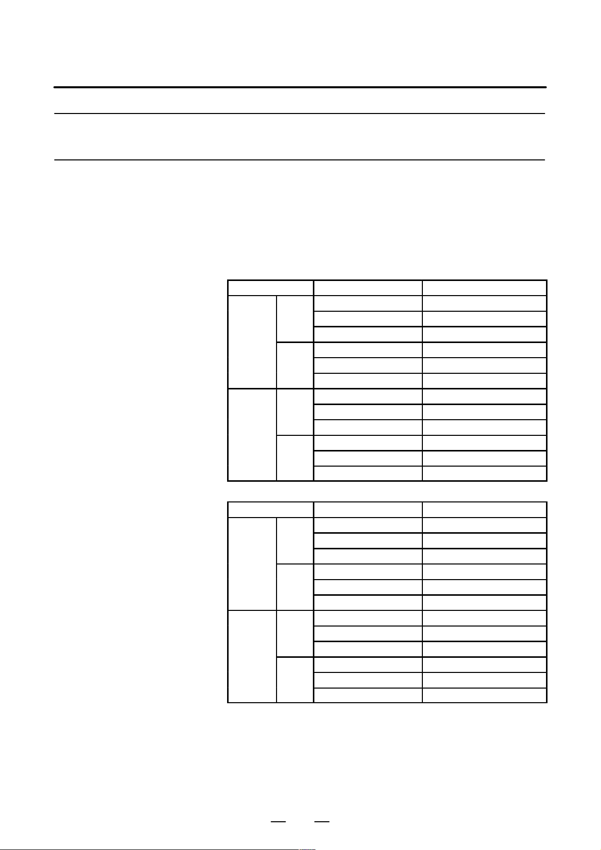
1020 Name of the axis used for programming for each axis
[Data type] Byte axis
Set the name of the program axis for each control axis, with one of the
values listed in the following table:
Axis
name
Setting Axis
name
X 88 U 85 A 65 E 69
Y 89 V 86 B 66
Z 90 W 87 C 67
Setting Axis
name
Setting Axis
Setting
name
4
Page 24

B–63833EN–1/02
1. AXIS CONTROL
NOTE
1 With the T series, when G code system A is used, neither
U, V , nor W can be used as an axis name. Only when G code
system B or C is used, U, V, and W can be used as axis
names.
2 The same axis name cannot be assigned to more then one
axis.
3 When the secondary auxilliary function (option) is provided,
the address used by the secondary auxilliary function
(address B with the T series or, with the M series, the
address specified in parameter No.3460) cannot be used as
an axis name.
4 With the T series, when address C or A is used for direct
drawing dimension programming (when the CCR
parameter (bit 4 of parameter No.3405) is set to 1),
addresses C or A cannot be used as an axis name.
5 Only with the T series, address E can be used as an axis
name. Address E cannot be used with the M series. When
address E is used as an axis name, note the following:
– When G code system A is used, address E is always
assigned to an absolute command.
– When an equal–lead threading command (G32) is
issued in the FS10/11 tape format. Use address F to
specify the thread lead.
Reference item
Series 0i–B
Series 0i Mate–B
OPERATOR’S MANUAL
(M series) (B–63844EN)
OPERATOR’S MANUAL
(T series) (B–63834EN)
OPERATOR’S MANUAL
(M series) (B–63864EN)
OPERATOR’S MANUAL
(T series) (B–63854EN)
II.2.2 NAMES OF AXES
II.2.2 NAMES OF AXES
II.2.2 NAMES OF AXES
II.2.2 NAMES OF AXES
5
Page 25
1. AXIS CONTROL
machine
machine
machine
machine
1.2.2
Increment System
B–63833EN–1/02
General
The increment system consists of the least input increment (for input ) and
least command increment (for output). The least input increment is the
least increment for programming the travel distance. The least command
increment is the least increment for moving the tool on the machine. Both
increments are represented in mm, inches, or degrees.
The increment system is classified as either IS–B or IS–C (Tables 1.2.2(a)
and 1.2.2 (b)). Select IS–B or IS–C using bit 1 (ISC) of parameter 1004.
Table 1.2.2 (a) Increment system IS–B
Least input increment Least command increment
Metric mm 0.001mm(Diameter) 0.0005mm
system
machine
Inch mm 0.001mm(Diameter) 0.00005inch
system
machine
input
inch 0.0001inch(Diameter) 0.0005mm
input
input
inch 0.0001inch(Diameter) 0.00005inch
input
0.001mm(Radius) 0.001mm
0.001deg 0.001deg
0.0001inch(Radius) 0.001mm
0.001deg 0.001deg
0.001mm(Radius) 0.0001inch
0.001deg 0.001deg
0.0001inch(Radius) 0.0001inch
0.001deg 0.001deg
Table 1.2.2 (b) Increment system IS–C
Least input increment Least command increment
Metric mm 0.0001mm(Diameter) 0.00005mm
system
machine
Inch mm 0.0001mm(Diameter) 0.000005inch
system
machine
input
inch 0.00001inch(Diameter) 0.00005mm
input
input
inch 0.00001inch(Diameter) 0.000005inch
input
0.0001mm(Radius) 0.0001mm
0.0001deg 0.0001deg
0.00001inch(Radius) 0.0001mm
0.0001deg 0.0001deg
0.0001mm(Radius) 0.00001inch
0.0001deg 0.0001deg
0.00001inch(Radius) 0.00001inch
0.0001deg 0.0001deg
6
Page 26
B–63833EN–1/02
Parameter
1. AXIS CONTROL
NOTE
Diameter programming is used only for T series. Diameter
programming or radius programming is determined by
parameter DIAx (No. 1006#3) for each axis. Also,
parameter IPR (No. 1004#7) can make the least input
increment of IS–B and IS–C ten times the least command
increment on each axis.
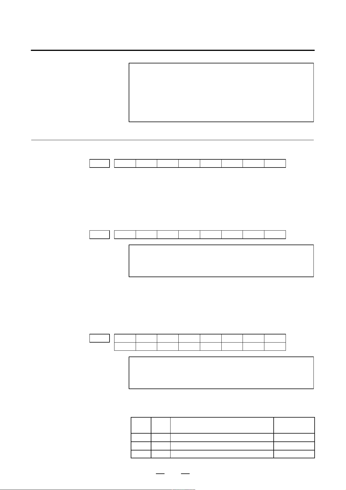
#7 #6 #5 #4 #3 #2 #1 #0
0000 INI
The following parameter can be set at “Setting screen”.
[Data type] Bit
INI Unit of input
0 : In mm
1 : In inches
#7 #6 #5 #4 #3 #2 #1 #0
1001 INM
NOTE
When this parameter is set, the power must be turned off
before operation is continued.
[Data type] Bit
INM Least command increment on the linear axis
0 : In mm (metric system machine)
1 : In inches (inch system machine)
#7 #6 #5 #4 #3 #2 #1 #0
IPR1004
IPR
ISC
ISC ISA
NOTE
After setting this parameter, turn the power of f then on again
so that the setting will take effect.
[Data type] Bit
ISA, ISC The least input increment and least command increment are set.
ISC ISA Least input increment and
least command increment
0 0 0.001mm, 0.001deg, or 0.0001inch IS-B
0 1 0.01mm, 0.01deg, or 0.001inch IS-A
1 0 0.0001mm, 0.0001deg, or 0.00001inch IS-C
7
Symbol
Page 27
1. AXIS CONTROL
B–63833EN–1/02
NOTE
IS–A is not available.
IPR Whether the least input increment for each axis is set to a value 10 times as
large as the least command increment is specified, in increment systems
of IS–B and IS–C, mm input.
0 : The least input increment is not set to a value 10 times as large as the
least command increment.
1 : The least input increment is set to a value 10 times as large as the least
command increment.
If IPR is set to 1, the least input increment is set as follows:
Input increment Least input increment
IS-B 0.01 mm, 0.01 deg, or 0.0001 inch
IS-C 0.001 mm, 0.001 deg, or 0.00001 inch
NOTE
For IS–A, the least input increment cannot be set to a value
10 times as large as the least command increment.
When inch of input is specified, the least input increment
does not become 10 times as large as the least command
increment.
Reference item
#7 #6 #5 #4 #3 #2 #1 #0
1006 DIAx
NOTE
When this parameter is changed, turn off the power before
continuing operation.
[Data type] Bit axis
DIAx Either a diameter or radius is set to be used for specifying the amount of
travel on each axis.
0 : Radius
1 : Diameter
OPERATOR’S MANUAL
(M series) (B–63844EN)
Series 0i–B
OPERATOR’S MANUAL
(T series) (B–63834EN)
OPERATOR’S MANUAL
(M series) (B–63864EN)
Series 0i Mate–B
OPERATOR’S MANUAL
(T series) (B–63854EN)
II.2.3 Increment System
II.2.3 Increment System
II.2.3 Increment System
II.2.3 Increment System
8
Page 28

B–63833EN–1/02
1.2.3
Specifying the Rotation
Axis
1. AXIS CONTROL
General
Parameter
Bit 0 (ROTx) of parameter 1006 can be used to set each axis to a linear
axis or rotation axis. Bit 1 (ROSx) of parameter 1006 can be used to select
the rotation axis type, A or B, for each axis. See the explanation of the
parameters for details of types A and B.
When the roll over function is used, the values displayed for absolute
coordinates are rounded by the shift amount per rotation, as set in
parameter No. 1260. This can prevent coordinates for the rotation axis
from overflowing. Displayed values for relative coordinates are also
rounded by the angle corresponding to one rotation when bit 2 (RRLx) of
parameter No. 1008 is set to 1. The roll–over function is enabled by
setting bit 0 (ROAx) of parameter 1008 to 1.
For an absolute command, the coordinates after the tool has moved are
values rounded by the angle corresponding to one rotation set in
parameter No. 1260. The tool moves in the direction in which the final
coordinates are closest when bit 1 of parameter No. 1008 is set to 0. For
an incremental command, the tool moves the angle specified in the
command.
#7 #6 #5 #4 #3 #2 #1 #0
1006 ROSx ROTx
NOTE
After setting this parameter, turn the power of f then on again
so that the setting will take effect.
[Data type] Bit axis
ROTx, ROSx Setting linear or rotation axis.
ROSx ROTx Meaning
0 0 Linear axis
(1) Inch/metric conversion is done.
(2) All coordinate values are linear axis type.
(Not rounded in 0 to 360°)
(3) Stored pitch error compensation is linear axis type
(Refer to parameter No. 3624)
0 1 Rotation axis (A type)
(1) Inch/metric conversion is not done.
(2) Machine coordinate values are rounded in 0 to 360_. Ab-
solute coordinate values and relative coordinate values
are rounded or not rounded by parameter No. 1008#0
and #2.
(3) Stored pitch error compensation is the rotation type. (Re-
fer to parameter No. 3624)
(4) Automatic reference position return (G28, G30) is done in
the reference position return direction and the move
amount does not exceed one rotation.
9
Page 29

1. AXIS CONTROL
B–63833EN–1/02
ROSx MeaningROTx
1 0 Setting is invalid (unused)
1 1 Rotation axis (B type)
(1) Inch/metric conversion is not done.
(2) Machine coordinate values, absolute coordinate values
and relative coordinate values are linear axis type. (Is not
rounded in 0 to 360_)
(3) Stored pitch error compensation is linear axis type (Refer
to parameter No. 3624)
(4) The rotation axis roll over function and index table index-
ing function (M series) cannot be used.
#7 #6 #5 #4 #3 #2 #1 #0
1008 RRLx RABx ROAx
NOTE
After setting this parameter, turn the power of f then on again
so that the setting will take effect.
[Data type] Bit axis
ROAx The roll–over function of a rotation axis is
0 : Invalid
1 : Valid
NOTE
ROAx specifies the function only for a rotation axis (for
which ROTx, #0 of parameter No. 1006, is set to 1)
RABx In the absolute commands, the axis rotates in the direction
0 : In which the distance to the target is shorter.
1 : Specified by the sign of command value.
NOTE
RABx is valid only when ROAx is 1.
RRLx Relative coordinates are
0 : Not rounded by the amount of the shift per one rotation
1 : Rounded by the amount of the shift per one rotation
NOTE
1 RRLx is valid only when ROAx is 1.
2 Assign the amount of the shift per one rotation in parameter
No. 1260.
10
Page 30
B–63833EN–1/02
1. AXIS CONTROL
1260 Amount of a shift per one rotation of a rotation axis
NOTE
1 After setting the parameter, turn off the power once and turn
it on again to operate the machine.
2 This parameter is valid only when ROAx = 1.
[Data type] Two–word axis
[Valid data range] 1000 to 9999999
Note
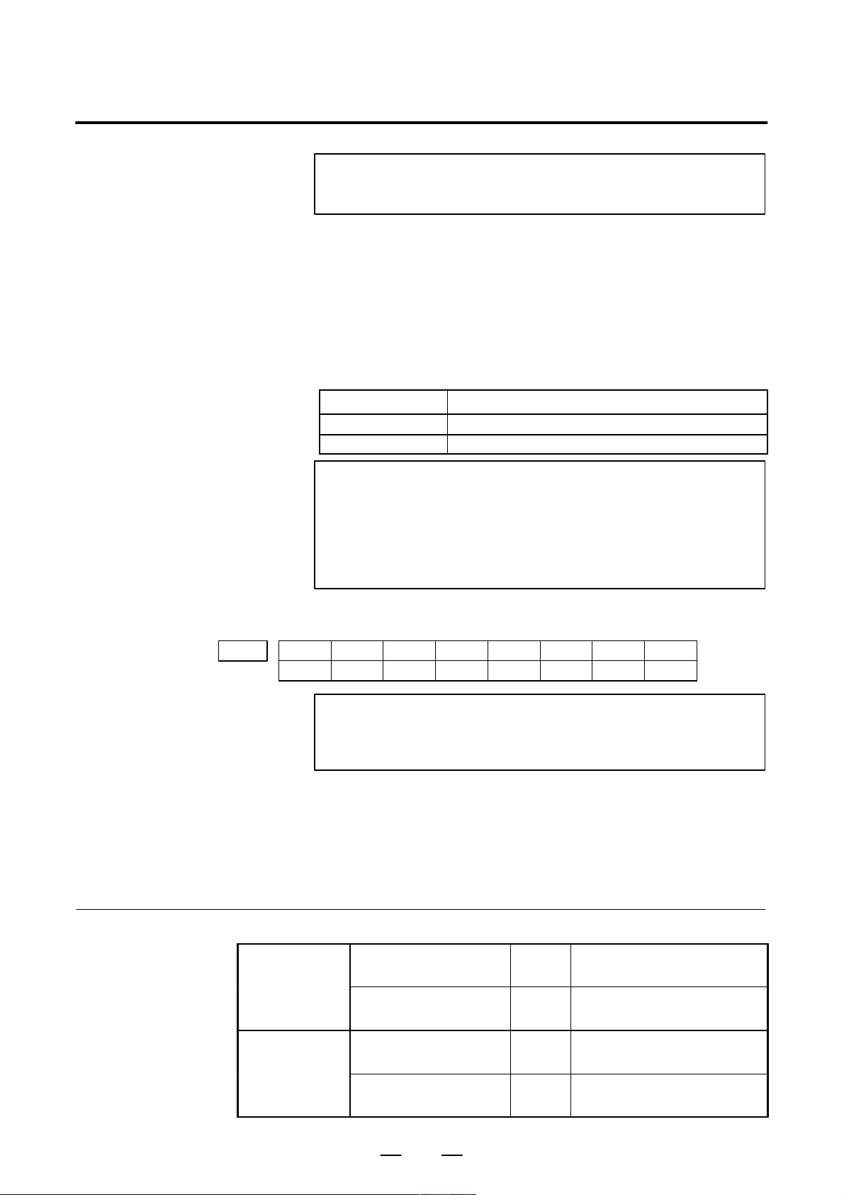
Reference item
[Unit of data]
Series 0i–B
Increment system Unit of data Standard value Unit
IS–A 0.01 36000
IS–B 0.001 360000
IS–C 0.0001 3600000
deg
Set the amount of a shift per one rotation of a rotation axis.
NOTE
Rotary axis roll–over function cannot be used together with
the indexing function of the index table.
OPERATOR’S MANUAL
(M series) (B–63844EN)
OPERATOR’S MANUAL
(T series) (B–63834EN)
II.20.2 Rotary Axis Roll–over
II.18.2 Rotary Axis Roll–over
11
Page 31

1. AXIS CONTROL
1.2.4
Outputting the
Movement State of an
Axis
B–63833EN–1/02
General
Signal
Axis moving signals
MV1 – MV4 <F102>
[Classification] Output signal
[Output condition] The signals turn to “1” in the following cases:
The movement state of each axis can be output to the PMC.
[Function] These signals indicate that a control axis is moving.
The signals are provided for each control axis, and the number in the
signal name corresponds to the control axis number.
MV 1
1 ..... The 1st axis is moving.
2 ..... The 2nd axis is moving.
3 ..... The 3rd axis is moving.
::
::
. The corresponding axis has started moving.
. In manual handle feed mode, the handle feed axis of the corresponding
axis has been selected.
The signals turn to “0” in the following case:
. When the move command for the corresponding axis has been
distributed (when bit 6 (MVX) of parameter 3003 is 0)
. When deceleration for the corresponding axis has been completed and
the axis is set to the in–position condition. If in–position check is not
performed, when the deceleration for the corresponding axis is
completed. (When bit 6 (MVX) of parameter 3003 is 1)
Setting 1 in bit 7 (MVG) of parameter 3003 prevents these signals from
being output during drawing in dynamic graphics mode (drawing without
movement of the machine) in the T system.
12
Page 32

B–63833EN–1/02
Axis moving direction
signals
MVD1 – MVD4 <F106>
[Classification] Output signal
[Function] These signals indicate the movement direction of control axis.
[Output condition] “1” indicates the corresponding axes are moving in the minus direction,
1. AXIS CONTROL
They are provided for each control axis, and the number in the signal name
corresponds to the control axis number.
MVD 1
1 ..... The moving direction of the 1st axis is minus.
2 ..... The moving direction of the 2nd axis is minus.
3 ..... The moving direction of the 3rd axis is minus.
::
::
and “0” indicates they are moving in the plus direction.
CAUTION
These signals maintain their condition during a stop,
indicating the direction of the axes’ movement before
stopping.
Signal address
F102 MV4 MV3 MV2 MV1
F106 MVD4 MVD3 MVD2 MVD1
Parameter
D Setting the output format
of the axis moving signal
[Data type] Bit
MVX The axis moving signal is set to 0 when:
MVG While drawing using the dynamic graphics function (with no machine
#7 #6 #5 #4 #3 #2 #1 #0
#7 #6
MVG3003 MVX
MVX
#5 #4 #3 #2 #1 #0
0 : Distribution for the axis is completed. (The signal is set to 0 in
deceleration.)
1 : Deceleration of the axis is terminated, and the current position is in the
in–position.
When the deceleration–time in–position check is suppressed by
setting bit 5 (NCI) of parameter No. 1601, the signal is set to 0 at the
end of deceleration.
movement), the axis moving signal is:
0: Output
1: Not output
13
Page 33

1. AXIS CONTROL
Caution
1.2.5
Mirror Image
B–63833EN–1/02
CAUTION
Axis moving signals and axis moving direction signals are
output in both automatic and manual operations.
General
Mirror image can be applied to each axis, either by signals or by
parameters (setting input is acceptable). All movement directions are
reversed during automatic operation along axes to which a mirror image
is applied.
X
A
0
When MI1 signal turned to “1” at point A
Mirror image (Example for T series)
B
B’
Z
However, the following directions are not reversed:
– Direction of manual operation and direction of movement, from the
intermediate position to the reference position during automatic
reference position return (for the M and T series)
– Approach direction for single direction positioning (G60) and shift
direction for boring cycles (G76 and G87) (for M series only)
Signal
Mirror image signal
MI1 – MI4 <G106>
[Classification] Input signal
Mirror image check signals indicate whether mirror image is applied to
each axis. System variable #3007 contains the same information (refer
to the operator’s manual).
[Function] Apply mirror image to the specified axes.
[Operation] Apply mirror image to those axes for which the signals are 1.
These signals are provided for the controlled axes on a one–to–one basis.
A number appended to a signal represents the controlled axis number.
14
Page 34

B–63833EN–1/02
Mirror image check
signal
MMI1 – MMI4<F108>
1. AXIS CONTROL
MI 1
1 ..... Applies mirror image to the 1st axis.
2 ..... Applies mirror image to the 2nd axis.
3 ..... Applies mirror image to the 3rd axis.
::
::
The mirror image signal can be turned to “1” in the following cases:
a) During offset cancel;
b) When the CNC is in the automatic operation stop state and not in the
feed hold state.
[Classification] Output signal
[Function] These signals indicate the mirror image condition of each axis. The mirror
image is set by taking the logical sum of the signal from the MDI panel
and the input signal of the machine tool, then relaying the information to
the machine tool.
These signals are provided for every control axis; the numeral in the signal
name indicates the relevant control axis number.
MMI 1
1 ..... Mirror image is applied to the 1st axis
2 ..... Mirror image is applied to the 2nd axis
3 ..... Mirror image is applied to the 3rd axis
::
::
[Output condition] These signals turn to “1” when:
· Mirror image signal MIn of the corresponding axis is “1”; or
· Mirror image of the corresponding axis is turned on by setting data
from the MDI panel.
These signals turn to “0” when:
· Mirror image signal (MIn) of the corresponding axis is “0” and the
setting of the mirror image in the control unit is turned off.
Signal address
#7 #6 #5 #4 #3 #2 #1 #0
G106 MI4 MI3 MI2 MI1
#7 #6 #5 #4 #3 #2 #1 #0
F108 MMI4 MMI3 MMI2 MMI1
15
Page 35

1. AXIS CONTROL
Parameter
Warning
B–63833EN–1/02
#7 #6 #5 #4 #3 #2 #1 #0
0012 MIRx
The following parameter can be set at “Setting screen.”
[Data type] Bit axis
MIRx Mirror image for each axis
0 : Mirror image is off.
1 : Mirror image is on.
WARNING
1 When programmable mirror image (M series) and ordinary
mirror image are specified at the same time, programmable
mirror image is applied first.
2 No programmable mirror image (M series) affects mirror
image check signals MMI1 to MMI4 <F108>.
Caution
Reference item
CAUTION
Series 0i–B
Series 0i Mate–B
Even when the mirror image is applied, commands which do
not actuate mirror image (such as automatic reference
position return and manual operation) do not affect mirror
image check signals MMI1 to MMI4 <F108>.
OPERATOR’S MANUAL
(M series) (B–63844EN)
OPERATOR’S MANUAL
(T series) (B–63834EN)
OPERATOR’S MANUAL
(M series) (B–63864EN)
OPERATOR’S MANUAL
(T series) (B–63854EN)
III.4.8 Mirror Image
III.4.7 Mirror Image
III.4.8 Mirror Image
III.4.7 Mirror Image
16
Page 36

B–63833EN–1/02
1.2.6
Follow–up
1. AXIS CONTROL
General
D When follow–up is not
performed for the axes
for which the servo is
turned off
D When follow–up is
performed for the axes
for which the servo is
turned off
When position control is disabled for the controlled axes (when the servo
is off, during emergency stop, or during a servo alarm), if the machine is
moved, a positional error occurs. Follow–up is a function for changing
the current position of the CNC and reseting the error counter to zero.
Assuming a command corresponding to the error has been specified.
You can select whether to perform follow–up for axes when the servo is
turned off.
Follow–up is always performed during emergency stop or a servo alarm.
When signal *FLWU is 1 or bit 0 (FUPx) of parameter 1819 is 1,
follow–up is not performed. The error is added to the error counter as a
servo error. In this case, the machine moves to compensate for the error
when the servo off signal changes to 0.
In general, follow–up is not used if the machine is mechanically clamped
when position control is disabled for the controlled axes.
When *FLWU is “0”, the follow-up function is engaged. The present
position of the CNC is changed to reset the error counter to zero. The
machine tool remains in a deviated position, but since the present position
of the CNC changes correspondingly, the machine moves to the correct
position when the absolute command is next applied.
In general, follow–up should be used when motors are driven by
mechanical handles.
Signal
Follow–up signal
*FLWU <G007#5>
[Classification] Input signal
Signal address
[Function] Select whether to perform follow–up when the servo is turned off for those
axes for which bit 0 (FUPx) of parameter 1819 is 0.
[Operation] 0: Performs follow–up.
1: Does not perform follow–up.
#7 #6 #5 #4 #3 #2 #1 #0
G007 *FLWU
17
Page 37

1. AXIS CONTROL
Parameter
B–63833EN–1/02
#7 #6 #5 #4 #3 #2 #1 #0
1819 FUPx
[Data type] Bit axis
FUPx To perform follow–up when the servo is off for each axis.
0 : The follow–up signal, *FLWU, determines whether follow–up is
performed or not.
When *FLWU is 0, follow–up is performed.
When *FLWU is 1, follow–up is not performed.
1 : Follow–up is not performed.
CAUTION
When the index table indexing function (M series) is used,
be sure to set FUPx of the 4th axis to 1.
Reference item
CONNECTION MANUAL
(This manual)
1.2.7 Servo Off (Mechanical handle)
18
Page 38

B–63833EN–1/02
1.2.7
Servo Off
(Mechanical Handle)
1. AXIS CONTROL
General
Signal
Servo off signal
SVF1 – SVF4 <G126>
[Classification] Input signal
[Function] Select whether to place each axis in the servo off state.
Place the controlled axes in the servo off state, stop the current to the servo
motor, which disables position control. However, the position detection
feature functions continuously, so the current position is not lost.
These signals are used to prevent the servo motors from overloading when
the tools on the axes are mechanically clamped under certain machining
conditions on the machine, or to move the machine by driving the motors
by mechanical handles.
These signals are provided for the controlled axes on a single axis basis.
A number appended to a signal represents a controlled axis number.
SVF 1
Signal address
1 ..... Servo off for the first axis
2 ..... Servo off for the second axis
3 ..... Servo off for the third axis
::
[Operation] These signals put the axes for which the signals are 1 in the servo off state
(the current to the servo motor is stopped). This disables position control.
However, the position detection feature continues to function, so the
current position is not lost.
#7 #6 #5 #4 #3 #2 #1 #0
G126 SVF4 SVF3 SVF2 SVF1
19
Page 39

1. AXIS CONTROL
Caution
B–63833EN–1/02
CAUTION
1 In general, interlock is applied to an axis while the servo off
signal for that axis is 1.
2 When one of these signals turns to “1”, the servo motor is
turned off. The mechanical clamp is done by using the
auxiliary function. Set the timing for the auxiliary function,
mechanical clamp and servo off signals as shown in the
diagram below. The clamp command auxiliary function
should be executed only after the distribution end signal
(DEN) turned to “1”.
Reference item
CONNECTION MANUAL
(This manual)
MF
Machine
clamp
SVF1, ...
FIN
Clamp command
Servo off state
1.2.6 Follow–up
Unclamp command
20
Page 40

B–63833EN–1/02
1.2.8
Position Switch
1. AXIS CONTROL
General
Signal
Position switch signal
PSW01 – PSW16
<F070#0 – F071#7>
[Classification] Output signal
[Function] Indicates that the machine coordinates along the controlled axes specified
[Output condition] These signals are 1 in the following case:
Position switch signals can be output to the PMC while the machine
coordinates along a controlled axes are within a specified ranges.
by parameters (6910 to 6925) are within the ranges specified by
parameters (6930 to 6945 and 6950 to 6965). Up to 16 position switch
signals can be output.
(Using 11 or more position switches requires setting the EPS parameter
(bit 1 of No. 6901.)
· When the machine coordinates along the controlled axes are within the
specified ranges.
Signal address
These signals are 0 in the following case:
· When the machine coordinates along the controlled axes are not within
the specified ranges.
#7 #6 #5 #4 #3 #2 #1 #0
PSW08F070 PSW07 PSW06 PSW05 PSW04 PSW03 PSW02 PSW01
PSW16F071 PSW15 PSW14 PSW13 PSW12 PSW11 PSW10 PSW09
21
Page 41

1. AXIS CONTROL
Parameter
D Increasing the number of
position switch signals
B–63833EN–1/02
#7
6901
[Data type] Bit
IGP During follow–up for the absolute position detector, position switch
EPS The number of position switches is:
PCM Position switch signals are output:
PSF In AI advanced preview control or advanced preview control mode,
#6 #5 #4 #3
PSF
#2
PCM#1EPS
#0
IGP
signals are:
0 : Output
1 : Not output
0 : Up to 10.
1 : Up to 16.
0 : Without considering acceleration/deceleration and servo delay.
1 : With considering acceleration/deceleration and servo delay.
position switches are:
0 : Not used.
1 : Used.
To use the position switches in any of the following modes, set this
parameter:
AI advanced preview control mode or advanced preview control mode
NOTE
The position switch signals are output considering
acceleration/deceleration after interpolation and servo
delay. Acceleration/deceleration after interpolation and
servo delay are considered even for position switch signal
output in a mode other than the AI advanced preview control
and advanced preview control modes. When this
parameter is set to 1, however, signals are output from the
position switches at different times from the specified ones.
22
Page 42

B–63833EN–1/02
D Setting the
correspondence
between the position
switch signals and the
controlled axes
1. AXIS CONTROL
6910 Axis corresponding to the first position switch
6911 Axis corresponding to the second position switch
6912 Axis corresponding to the third position switch
6913 Axis corresponding to the fourth position switch
6914 Axis corresponding to the fifth position switch
6915 Axis corresponding to the sixth position switch
6916 Axis corresponding to the seventh position switch
6917 Axis corresponding to the eighth position switch
6918 Axis corresponding to the ninth position switch
6919 Axis corresponding to the tenth position switch
6920 Axis corresponding to the eleventh position switch
6921 Axis corresponding to the twelveth position switch
6922 Axis corresponding to the thirteenth position switch
6923 Axis corresponding to the fourteenth position switch
6924 Axis corresponding to the fifteenth position switch
6925 Axis corresponding to the sixteenth position switch
[Data type] Byte
[Valid data range] 0 to Number of controlled axes
These parameters sequentially specify the numbers of the controlled axes
corresponding to the 1st through 16th position switch functions. The
corresponding position switch signal is output to the PMC when the
machine coordinate of the corresponding axis is within the range set in
parameters.
NOTE
1 Set 0 for the number corresponding to a position switch
which is not to be used.
2 Parameter Nos. 6920 to 6925 are valid only when bit 1
(EPS) of parameter No. 6901 is 1.
23
Page 43

1. AXIS CONTROL
D Setting the machine
coordinate ranges for
which the position
switch signals are output
D Maximum operation
range
6930 Maximum operation range of the first position switch
6931 Maximum operation range of the second position switch
6932 Maximum operation range of the third position switch
6933 Maximum operation range of the fourth position switch
6934 Maximum operation range of the fifth position switch
6935 Maximum operation range of the sixth position switch
6936 Maximum operation range of the seventh position switch
6937 Maximum operation range of the eighth position switch
6938 Maximum operation range of the ninth position switch
6939 Maximum operation range of the tenth position switch
B–63833EN–1/02
6940 Maximum operation range of the eleventh position switch
6941 Maximum operation range of the twelveth position switch
6942 Maximum operation range of the thirteenth position switch
6943 Maximum operation range of the fourteenth position switch
6944 Maximum operation range of the fifteenth position switch
6945 Maximum operation range of the sixteenth position switch
[Data type] 2–word
[Unit of data]
Increment system IS–A IS–B IS–C Unit
Metric machine 0.01 0.001 0.0001 mm
Inch machine 0.001 0.0001 0.00001 inch
Rotation axis 0.01 0.001 0.0001 deg
[Valid data range] –99999999 to 99999999
These parameters sequentially set the maximum operation ranges of the
1st through 16th position switches.
NOTE
Parameter Nos. 6940 to 6945 are valid only when bit 1
(EPS) of parameter No. 6901 is 1.
24
Page 44

B–63833EN–1/02
D Minimum operation
range
1. AXIS CONTROL
6950 Minimum operation range of the first position switch
6951 Minimum operation range of the second position switch
6952 Minimum operation range of the third position switch
6953 Minimum operation range of the fourth position switch
6954 Minimum operation range of the fifth position switch
6955 Minimum operation range of the sixth position switch
6956 Minimum operation range of the seventh position switch
6957 Minimum operation range of the eighth position switch
6958 Minimum operation range of the ninth position switch
6959 Minimum operation range of the tenth position switch
6960 Minimum operation range of the eleventh position switch
6961 Minimum operation range of the twelveth position switch
6962 Minimum operation range of the thirteenth position switch
6963 Minimum operation range of the fourteenth position switch
6964 Minimum operation range of the fifteenth position switch
6965 Minimum operation range of the sixteenth position switch
[Data type] 2–word
[Unit of data]
Increment system IS–A IS–B IS–C Unit
Metric machine 0.01 0.001 0.0001 mm
Inch machine 0.001 0.0001 0.00001 inch
Rotation axis 0.01 0.001 0.0001 deg
[Valid data range] –99999999 to 99999999
These parameters sequentially set the minimum operation ranges of the
1st through 16th position switches.
NOTE
Parameter Nos. 6960 to 6965 are valid only when bit 1
(EPS) of parameter No. 6901 is 1.
25
Page 45

1. AXIS CONTROL
1.3
ERROR COMPENSATION
1.3.1
Stored Pitch Error
Compensation
B–63833EN–1/02
General
If pitch error compensation data is specified, pitch errors of each axis can
be compensated in detection units per axis.
Pitch error compensation data is set for each compensation position at the
intervals specified for each axis. The origin of compensation is the
reference position to which the tool is returned.
Pitch error compensation data can be set with external devices such as the
Handy File (see Operator’s manual). Compensation data can also be set
directly with the MDI panel.
The following parameters must be set for pitch error compensation. Set
the pitch error compensation value for each pitch error compensation
position number set by these parameters.
In the following example, 33 is set for the pitch error compensation
number at the reference position.
Pitch error compensation value (absolute value)
Compensation number for
the compensation position
having the largest value
(No. 3622)
Compensation number for the
reference position (No. 3620)
3
2
1
333231
34 35 36 37
Reference position
Compensation number for the
compensation position having the
smallest value (No. 3621)
Compensation
position number
Compensation
value to be set
–3+1+1+1+2–1 –3
–1
–2
Compensation magnification
parameter (No. 3623)
Compensation interval
parameter (No. 3624)
34 35 36 3731 32 33
· Pitch error compensation position at the reference position (for each
axis): Parameter 3620
· Pitch error compensation position having the smallest value (for each
axis): Parameter 3621
· Pitch error compensation position having the largest value (for each
axis): Parameter 3622
· Pitch error compensation magnification (for each axis): Parameter
3623
26
Page 46

B–63833EN–1/02
1. AXIS CONTROL
· Interval of the pitch error compensation positions (for each axis):
Parameter 3624
Procedure for displaying
and setting the pitch
error compensation data
PITCH
Continuous menu key
1 Set the following parameters:
⋅ Pitch error compensation position at the reference position (for
each axis): Parameter 3620
⋅ Pitch error compensation position having the smallest value (for
each axis): Parameter 3621
⋅ Pitch error compensation position having the largest value (for
each axis): Parameter 3622
⋅ Pitch error compensation magnification (for each axis):
Parameter 3623
⋅ Interval of the pitch error compensation positions (for each
axis): Parameter 3624
SYSTEM
2 Press function key
3 Press the continuous menu key
[PITCH].
key
.
, then press chapter selection soft
The following screen is displayed:
PIT–ERROR SETTING O0000 N00000
NO. DATA
0000 0
0001 0
0002 0
0003 0
(X)
0004 0
0005 0
0006 0
0007 0
0008 0
0009 0
> _
MEM **** *** *** 16:05:59
[ NO.SRH ][ ON:1 ][ OFF:0 ][ +INPUT ][ –INPUT ]
NO. DATA
0010 0
0011 0
0012 0
0013 0
0014 0
0015 0
0016 0
0017 0
0018 0
0019 0
NO. DATA
0020 0
0021 0
0022 0
0023 0
0024 0
0025 0
0026 0
0027 0
0028 0
0029 0
4 Move the cursor to the compensation position number to be set in
either of the following ways:
⋅ Enter the compensation position number and press the
[NO.SRH] soft key.
⋅ Move the cursor to the compensation position number using the
page keys,
and
and
PAGE
.
, and cursor keys, , , ,
PAGE
5 Enter a value with numeric keys and press the [INPUT] soft key.
27
Page 47

1. AXIS CONTROL
Explanations
B–63833EN–1/02
D Specifying the
compensation position
D Compensation position
number
D Interval of compensation
positions
To assign the compensation positions for each axis, specify the positive
direction or the negative direction relative to the compensation position
No. of the reference position. If the machine stroke exceeds the specified
range on either the positive direction or the negative direction, the pitch
error compensation does not apply beyond the range.
1024 compensation positions from No. 0 to 1023 are available on the
pitch error setting screen. Assign arbitrary positions for each axis using
parameters.
The number of the compensation position at the reference position
(parameter 3620), number of the compensation position having the
smallest value (parameter 3621), and number of the compensation
position having the largest value (parameter 3622) must be set for each
axis.
The name of each axis is displayed before the smallest compensation
position number on the pitch error setting screen.
The pitch error compensation positions are equally spaced to parameter
No. 3624. Set the space between two adjacent positions for each axis.
The minimum interval between pitch error compensation positions is
limited and obtained from the following equation:
Minimum interval of pitch error compensation positions = maximum
feedrate (rapid traverse rate)/3750
Unit:
· Minimum interval of pitch error compensation positions: mm, inches,
deg.
· Maximum feed rate: mm/min, inch/min, deg/min
Examples
D For linear axis
⋅ Machine stroke: –400 mm to +800 mm
⋅ Interval between the pitch error compensation positions: 50 mm
⋅ No. of the compensation position of the reference position: 40
If the above is specified, the No. of the farthest compensation position in
the negative direction is as follows:
No. of the compensation position of the reference position – (Machine
stroke on the negative side/Interval between the compensation
positions) + 1
= 40 – 400/50 + 1= 33
No. of the farthest compensation position in the positive direction is as
follows:
No. of the compensation position of the reference position + (Machine
stroke on the positive side/Interval between the compensation
positions)
= 40 + 800/50= 56
28
Page 48

B–63833EN–1/02
1. AXIS CONTROL
The correspondence between the machine coordinate and the
compensation position No. is as follows:
–400 –350 –100 –50
0
50 100 750 800
Machine
coordinate (mm)
Compensation
position number.
33 39 40 41 42 56
Compensation values are output at the positions indicated by .
Therefore, set the parameters as follows:
Parameter Setting value
3620 : Compensation number for the reference position
3621 : Smallest compensation position number
3622 : Largest compensation position number
3623 : Compensation magnification
3624 : Interval between pitch error compensation positions
40
33
56
1
50000
The compensation amount is output at the compensation position No.
corresponding to each section between the coordinates.
The following is an example of the compensation amounts.
No
Compensation
value
33 34 35 36 37 38 39 40 41 42 43 44 45 46 47 48 49
–2 –1 –1+20 +10 +1+2+10 –1 –1 –2 0 +1 +2
Pitch error compensation value
(absolute value)
+4
+3
+2
–100
+1
0
100 200 300 400
–1
–2
–3
–4
33 34 35 36 37 38 39 40 41 42 43 44 45 46 47 48 49
–400
–300 –200
Reference
position
56
(mm)
1
29
Page 49

1. AXIS CONTROL
B–63833EN–1/02
D For rotary axis
⋅Amount of movement per rotation: 360°
⋅ Interval between pitch error compensation positions: 45°
⋅ No. of the compensation position of the reference position: 60
If the above is specified, the No. of the farthest compensation position in
the negative direction for the rotating axis is always equal to the
compensation position No. of the reference position.
The No. of the farthest compensation position in the positive direction is
as follows:
No. of the compensation position of the reference position + (Move
amount per rotation/Interval between the compensation positions)
= 60 + 360/45= 68
The correspondence between the machine coordinate and the
compensation position No. is as follows:
(+)
(61)
0.0
(68)
(60)
315.0
(67)
270.0
Reference position
45.0
(62)
90.0
(63)
(65)(64)
135.0
180.0
Compensation values are output at the positions indicated by .
(66)
225.0
Therefore, set the parameters as follows:
Parameter Setting value
3620 : Compensation number for the reference position 60
3621 : Smallest compensation position number 60
3622 : Largest compensation position number 68
3623 : Compensation magnification 1
3624 : Interval between pitch error compensation positions 45000
3625 : Movement value per rotation 360000
If the sum of the compensation values for positions 61 to 68 is not 0, pitch
error compensation values are accumulated for each rotation, causing
positional deviation.
The same value must be set for compensation positions 60 and 68.
30
Page 50

B–63833EN–1/02
Parameter
3620
The following is an example of compensation amounts.
No
Compensation
value
61 62 63 64 65 66 67
Number of the pitch error compensation position for the reference position
60 61 62 63 64 65 66 67 68
+1 –2+1+3–1 –1 –3+2+1
+4
+3
68
+2
(60)
+1
45 90 135 180225 270 315
for each axis
–1
–2
–3
–4
Pitch error compensation value
(absolute value)
Reference position
61 62 63 64 65 66 67
0
45 90 135 180225 270 315
1. AXIS CONTROL
68
(60)
61 62
0
45 90
(deg)
NOTE
After setting this parameter, turn the power of f then on again
so that the setting will take effect.
[Data type] Word axis
[Unit of data] Number
[Valid data range] 0 to 1023
Set the number of the pitch error compensation position for the reference
position for each axis.
3621
Number of the pitch error compensation position at extreme negative
NOTE
After setting this parameter, turn the power of f then on again
so that the setting will take effect.
[Data type] Word axis
position for each axis
[Unit of data] Number
[Valid data range] 0 to 1023
Set the number of the pitch error compensation position at the extreme
negative position for each axis.
31
Page 51

1. AXIS CONTROL
B–63833EN–1/02
3622
Number of the pitch error compensation position at extreme positive
position for each axis
NOTE
After setting this parameter, turn the power of f then on again
so that the setting will take effect.
[Data type] Word axis
[Unit of data] Number
[Valid data range] 0 to 1023
Set the number of the pitch error compensation position at the extreme
positive position for each axis.
NOTE
This value must be larger than the value of parameter (No.
3620).
3623 Magnification for pitch error compensation for each axis
NOTE
After setting this parameter, turn the power of f then on again
so that the setting will take effect.
[Data type] Byte axis
[Unit of data] 1
[Valid data range] 0 to 100
Set the magnification for pitch error compensation for each axis.
If the magnification is set to 1, the magnification is the same as the
detection unit.
3624 Interval between pitch error compensation positions for each axis
NOTE
After setting this parameter, turn the power of f then on again
so that the setting will take effect.
[Data type] Two–word axis
[Unit of data]
Increment system IS–A IS–B IS–C Unit
Metric machine 0.01 0.001 0.0001 mm
Inch machine 0.001 0.0001 0.00001 inch
Rotation axis 0.01 0.001 0.0001 deg
32
Page 52

B–63833EN–1/02
1. AXIS CONTROL
[Valid data range] 0 to 99999999
The pitch error compensation positions are equally spaced to parameter
No. 3624. Set the space between two adjacent positions for each axis.
The minimum interval between pitch error compensation positions is
limited and obtained from the following equation:
Minimum interval of pitch error compensation positions = maximum
feedrate (rapid traverse rate)/7500
Unit:
· Minimum interval of pitch error compensation positions: mm, inches,
deg.
· Maximum feed rate: mm/min, inch/min, deg/min
[Example] When the maximum rapid traverse rate is 15000 mm/min, the minimum
interval between pitch error compensation positions is 4 mm.
3625 Travel distance per revolution in pitch error compensation of rotation axis type
NOTE
When this parameter has been set, the power must be
turned off before operation is continued.
[Data type] 2–word axis
[Valid data range] 0 to 99999999
If the pitch error compensation of rotation axis type is performed (bit 1
(ROSx) of parameter No. 1006 is set to 0 and bit 0 (ROTx) of parameter
No. 1006 is set to 1), set the travel distance per revolution. The travel
distance per revolution does not have to be 360 degrees, and a cycle of
pitch error compensation of rotation axis type can be set.
However, the travel distance per revolution, compensation interval, and
number of compensation points must satisfy the following condition:
(Travel distance per revolution) = (Compensation interval) x
(Number of compensation points)
The compensation at each compensation point must be set so that the total
compensation per revolution equals 0.
NOTE
If 0 is set, the travel distance per revolution becomes 360
degrees.
33
Page 53

1. AXIS CONTROL
Warning
B–63833EN–1/02
WARNING
1 Compensation value range
Compensation values can be set within the range from –7
x compensation magnification (detection unit) to +7 x
compensation magnification (detection unit). The
compensation magnification can be set for each axis within
the range from 0 to 100 in parameter 3623.
2 Pitch error compensation of the rotary axis
For the rotating axis, the interval between the pitch error
compensation positions shall be set to one per integer of the
amount of movement (normally 360°) per rotation. The sum
of all pitch error compensation amounts per rotation must be
made to 0. Also, set the same compensation value to a
position and the same position with one rotation.
3 Conditions where pitch error compensation is not
performed
Note that the pitch error is not compensated in the following
cases:
· When the machine is not returned to the reference
position after turning on the power. This excludes the
case where an absolute position detector is employed.
· If the interval between the pitch error compensation
positions is 0.
· If the compensation position Nos. on the positive or
negative direction do not fall within the range of 0 to
1023.
· If the compensation position Nos. do not conform to the
following relationship:
Negative side x Reference position < Positive side
34
Page 54

B–63833EN–1/02
Reference item
1. AXIS CONTROL
Series 0i–B
Series 0i Mate–B
OPERATOR’S MANUAL
(M series) (B–63844EN)
OPERATOR’S MANUAL
(T series) (B–63834EN)
OPERATOR’S MANUAL
(M series) (B–63864EN)
III.8.6.3
III.8.6.4
III.11.5.2
III.8.6.3
III.8.6.4
III.11.5.2
III.8.6.3
III.8.6.4
III.11.5.2
III.8.6.3
Inputting pitch error compensation data
Outputting pitch error compensation data
Displaying and setting pitch error
compensation data
Inputting pitch error compensation data
Outputting pitch error compensation data
Displaying and setting pitch error
compensation data
Inputting pitch error compensation data
Outputting pitch error compensation data
Displaying and setting pitch error
compensation data
Inputting pitch error compensation data
OPERATOR’S MANUAL
(T series) (B–63854EN)
III.8.6.4
III.11.5.2
Outputting pitch error compensation data
Displaying and setting pitch error
compensation data
35
Page 55

1. AXIS CONTROL
1.3.2
Backlash
Compensation
General
B–63833EN–1/02
D Backlash compensation
Function for compensating for lost motion on the machine. Set a
compensation value in parameter No. 1851, in detection units from 0 to
"9999 pulses for each axis.
D Backlash compensation
for each rapid traverse
and cutting feed
More precise machining can be performed by changing the backlash
compensating value depending on the feedrate, the rapid traverse or the
cutting feed.
Let the measured backlash at cutting feed be A and the measured backlash
at rapid traverse be B. The backlash compensating value is shown below
depending on the change of feedrate (cutting feed or rapid traverse) and
the change of the direction of movement.
Change of feedrate
Change of direction
of movement
Same direction
Opposite direction
Cutting feed to
cutting feed
0 "α
"A "B "(B+α)
Rapid traverse
to rapid traverse
0
Rapid traverse
to cutting feed
@ a = (A–B)/2
@ The positive or negative direction for compensating values is the
direction of movement.
Stopped during cutting feed Stopped during rapid traverse
Cutting feed to
rapid traverse
" (*α)
" (B+α)
αα
AB
⇒⇒
a : Overrun
@ Assign the measured backlash at cutting feed (A) in parameter No.
1851 and that at rapid traverse (B) in parameter No. 1852.
36
Page 56

B–63833EN–1/02
Parameter
1. AXIS CONTROL
#7 #6 #5 #4 #3 #2 #1 #0
1800 RBK
[Data type] Bit
RBK Backlash compensation applied separately for cutting feed and rapid
traverse
0 : Not performed
1 : Performed
1851 Backlash compensating value for each axis
[Data type] Word axis
[Unit of data] Detection unit
[Valid data range] –9999 to +9999
Set the backlash compensating value for each axis.
When RBK is 1, set the backlash compensating value for cutting feed.
Caution
When the machine moves in the opposite direction from to the reference
position return direction after the power is turned on, the first backlash
compensation is performed.
1852 Backlash compensating value used for rapid traverse for each axis
[Data type] Word axis
[Unit of data] Detection unit
[Valid data range] –9999 to +9999
Set the backlash compensating value used in rapid traverse for each axis.
This parameter is valid when RBK is set to 1.
CAUTION
The backlash compensation for rapid traverse and cutting
feed is not performed until the first reference position return
is completed after the power is turned on. Under this state,
the normal backlash compensation is performed according
to the value specified in parameter No. 1851 irrespective of
a rapid traverse or a cutting feed.
Note
NOTE
When backlash compensation is applied separately for
cutting feed and rapid traverse, jog feed is regarded as
cutting feed.
37
Page 57

1. AXIS CONTROL
B–63833EN–1/02
1.4
SETTINGS RELATED TO SERVO– CONTROLLED AXES
1.4.1
Parameters Related to
Servo
General
The servo interface of the Series 16 features the following:
S Digitally controlled AC servo motor
S Motor feedback with serial pulse coders
(1)Absolute pulse coder with a resolution of 1,000,000 pulses/rev
(2)Absolute pulse coder with a resolution of 65,536 pulses/rev
(3)Incremental pulse coder with a resolution of 10,000 pulses/rev
S Scale feedback with A/B/Z signal interface
Explanation of terms frequently used in CNC
Least command increment
The minimum unit of a command to be given from CNC to the
machine tool
Detection unit
The minimum unit which can detect the machine tool position
Command multiplier (CMR)
A constant to enable the weight of CNC command pulses to meet the
weight of pulses from the detector
Detection multiplier (DMR)
A constant to enable the weight of CNC command pulses to meet the
weight of pulses from the detector
CAUTION
The relations among the least command increment,
detection unit, CMR, and DMR are as specified below.
Least command increment = CMR detection unit
Detection unit =
The flexible feed gear function in the digital servo defines
constant DMR using two parameters (Nos. 2084 and 2085)
n and m (DMR = n/m).
Move amount per revolution of motor
DMR number of pulses of detector per revolution
38
Page 58

B–63833EN–1/02
Parameter
1. AXIS CONTROL
#7 #6 #5 #4 #3 #2 #1 #0
1800 CVR
[Data type] Bit
CVR When velocity control ready signal VRDY is set ON before position
control ready signal PRDY comes ON
0 : A servo alarm is generated.
1 : A servo alarm is not generated.
#7 #6 #5 #4 #3 #2 #1 #0
1815 APCx APZx OPTx
NOTE
When this parameter has been set, the power must be
turned off before operation is continued.
[Data type] Bit axis
OPTx Position detector
0 : A separate pulse coder is not used.
1 : A separate pulse coder is used.
APZx Machine position and position on absolute position detector when the
absolute position detector is used
0 : Not corresponding
1 : Corresponding
WARNING
When an absolute position detector is used, after primary
adjustment is performed or after the absolute position
detector is replaced, this parameter must be set to 0, power
must be turned off and on, then manual reference position
return must be performed. This completes the positional
correspondence between the machine position and the
position on the absolute position detector, and sets this
parameter to 1 automatically.
APCx Position detector
0 : Other than absolute position detector
1 : Absolute position detector (absolute pulse coder)
#7 #6 #5 #4 #3 #2 #1 #0
1816 DM3x DM2x DM1x
NOTE
When this parameter has been set, the power must be
turned off before operation is continued.
39
Page 59

1. AXIS CONTROL
B–63833EN–1/02
[Data type] Bit axis
DM1x to DM3x Setting of detection multiplier
Set value
DM3x DM2x DM1x
0
0
0
0
1
1
1
1
0
0
1
1
0
0
1
1
0
1
0
1
0
1
0
1
NOTE
When the flexible feed gear is used, do not use these
parameters. Set the numerator and denominator of DMR
to an appropriate values in parameters 2084 and 2085
respectively.
1820 Command multiplier for each axis (CMR)
Detection multiplier
1/2
1
3/2
2
5/2
3
7/2
4
NOTE
When this parameter has been set, the power must be
turned off before operation is continued.
[Data type] Byte axis
Set a command multiplier indicating the ratio of the least command
increment to the detection unit for each axis.
Least command increment = detection unit x command multiplier
Relationship between the increment system and the least command
increment
Increment system IS–A IS–B IS–C Unit
Metric machine 0.01 0.001 0.0001 mm
Inch machine 0.001 0.0001 0.00001 inch
Rotation axis 0.01 0.001 0.0001 deg
The value set in the parameter is obtained as follows:
(1)When command multiplier is 1/2 to 1/27
Least command increment
Set value = + 100
1
(Command multiplier)
Valid data range: 102 to 127
40
Page 60

B–63833EN–1/02
1. AXIS CONTROL
(2)When command multiplier is 1 to 48
Set value = 2 command multiplier
Valid data range: 2 to 96
NOTE
When command multiplier is 1 to 48, the set value must be
determined so that an integer can be set for command
multiplier.
1821 Reference counter size for each axis
[Data type] Two–word axis
[Valid data range] 0 to 99999999
Set the size of the reference counter.
NOTE
When this parameter has been set, the power must be
turned off before operation is continued.
1825 Servo loop gain for each axis
[Data type] Word axis
[Unit of data] 0.01 s
–1
[Valid data range] 1 to 9999
Set the loop gain for position control for each axis.
When the machine performs linear and circular interpolation (cutting), the
same value must be set for all axes. When the machine requires
positioning only, the values set for the axes may differ from one another.
As the loop gain increases, the response by position control is improved.
A too large loop gain, however, makes the servo system unstable.
The relationship between the positioning deviation (the number of pulses
counted by the error counter) and the feedrate is expressed as follows:
Positioning deviation =
Unit : Positioning deviation: mm, inches, or deg
Feedrate: mm/min, inches/min, or deg/min
Loop gain: s
1828 Positioning deviation limit for each axis in movement
–1
60
feedrate
(loop gain)
[Data type] Two–word axis
[Unit of data] Detection unit
[Valid data range] 0 to 99999999
41
Page 61

1. AXIS CONTROL
[Valid data range] 0 to 32767
B–63833EN–1/02
Set the positioning deviation limit in movement for each axis.
If the positioning deviation exceeds the positioning deviation limit during
movement, a servo alarm is generated, and operation is stopped
immediately (as in emergency stop).
Generally, set the positioning deviation for rapid traverse plus some
margin in this parameter.
1829 Positioning deviation limit for each axis in the stopped state
[Data type] Word axis
[Unit of data] Detection unit
Set the positioning deviation limit in the stopped state for each axis.
If, in the stopped state and the positioning deviation exceeds the
positioning deviation limit set for stopped state, a servo alarm is
generated, and operation is stopped immediately (as in emergency stop).
1850 Grid shift for each axis
[Data type] Two–word axis
[Unit of data] Detection unit
[Valid data range] –99999999 to +99999999
A grid shift is set for each axis.
T o shift the reference position, the grid can be shifted by the amount set in
this parameter. Up to the maximum value counted by the reference
counter can be specified as the grid shift.
NOTE
When this parameter has been set, the power must be
turned off before operation is continued.
42
Page 62

B–63833EN–1/02
1.4.2
Absolute Position
Detection
1. AXIS CONTROL
General
Signal
Absolute position
detector battery voltage
low alarm signal
PBATL <F172#7>
[Classification] Output signal
[Function] Notifies that the life of the absolute position detector battery, which is
[Operation] The signal becomes 1 when:
Even when the power to the CNC is turned off, a battery–powered pulse
coder stores the current position. No reference position return is required
when the power to the CNC is restored.
used to keep the machine position even when the CNC power is off, is
about to expire.
Generally, this signal is used to turn on a lamp for calling the operator’s
attention.
· The battery voltage for the absolute position detector becomes lower
than or equal to the rating.
The battery need be replaced in the immediate future.
Absolute position
detector battery voltage
zero alarm signal
PBATZ <F172#6>
[Classification] Output signal
[Function] Notifies that the life of the absolute position detector battery, which is
[Operation] The signal becomes 1 when:
The signal becomes 0 when:
· The battery voltage for the absolute position detector is higher than or
equal to the rating.
used to keep the machine position even when the CNC power is off, has
expired.
· The battery voltage for the absolute position detector becomes 0 V.
The battery need be replaced before the CNC power is turned off.
The signal becomes 0 when:
· The battery voltage for the absolute position detector is higher than or
equal to 0 V.
43
Page 63

1. AXIS CONTROL
Signal address
Parameter
#7
PBATLF172
#7 #6 #5 #4 #3 #2 #1 #0
1815 APCx
#6
PBATZ
#5 #4 #3 #2 #1 #0
NOTE
When this parameter has been set, the power must be
turned off before operation is continued.
[Data type] Bit axis
APCx Position detector
0: Other than absolute position detector
1: Absolute position detector (absolute pulse coder)
B–63833EN–1/02
44
Page 64

B–63833EN–1/02
1.4.3
FSSB Setting
1. AXIS CONTROL
Overview
Connecting the CNC control section to servo amplifiers via a high–speed
serial bus (F ANUC Serial Servo Bus, or FSSB), which uses only one fiber
optics cable, can significantly reduce the amount of cabling in machine
tool electrical sections.
In a system using the FSSB, it is necessary to set up the following
parameters to specify its axes. (The other parameters should be specified
as usual.)
D Parameter No. 1023
D Parameter No. 1905
D Parameter Nos. 1910 to 1919
D Parameter Nos. 1936 and 1937
These parameters can be specified using the following methods:
1. Manual setting 1
Parameters are defaulted according to the setting of parameter No.
1023. There is no need to specify parameter Nos. 1905, 1910 to 1919,
1936 and 1937. No automatic setting is used. Note that some
functions are unusable.
2. Automatic setting
Axis settings are calculated automatically according to the
interrelationships between axes and amplifiers entered on the FSSB
setting screen. Parameter Nos. 1023, 1905, 1910 to 1919, 1936, and
1937 are specified automatically according to the results of the
calculation.
3. Manual setting 2
Parameter Nos. 1023, 1905, 1910 to 1919, 1936, and 1937 are
specified according to manually entered values. The user must be
totally familiar with the meaning of each parameter before entering
any values.
45
Page 65

1. AXIS CONTROL
B–63833EN–1/02
Slave
Manual setting 1
In an FSSB–based system, a fiber optics cable is used to connect the CNC
to servo amplifiers and separate detector interface units. These amplifiers
and separate detector interface units are called slaves. The two–axis
amplifier consists of two slaves, and the three–axis amplifier consists of
three slaves. The slaves are numbered 1, 2, ..., 10 (slave number)
sequentially, with that nearest to the CNC starting at number 1.
CNC
Controlled
axis
number
Program
axis name
(No. 1020)
1X
2Y
3Z
4A
Single–axis
amplifier
Two–axis
amplifier
M1
Single–axis
amplifier
M1: First separate detector interface unit
Slave
No.
1
2
3
4
5
The manual setting 1 is valid when the following parameter have the
following values:
Bit 0 of parameter No. 1902 = 1
Bit 1 of parameter No. 1902 = 0
Parameter Nos. 1910 to 1919 = all 0s
By manual setting 1, the value set for parameter No. 1023 when the power
is switched on is regarded as a slave number. Specifically, an axis for
which parameter No. 1023 is set to 1 is connected to the amplifier nearest
to the CNC, while an axis for which parameter No. 1023 is set to 2 is the
second one from the CNC.
CNC
Controlled
axis
number
Program
axis name
(No. 1020)
1X1
2Y3
3Z4
4A2
Servo axis
number
(No. 1023)
Two–axis
amplifier
Single–axis
amplifier
Single–axis
amplifier
X
A
Y
Z
By manual setting 1, some of the following functions and values cannot
be used, as described below. They should be used with automatic setting
or manual setting 2.
D No separate detector interface unit can be used; hence, no separate
position detectors can be used.
D No number can be skipped in parameter No. 1023; for example,
number 3 cannot be used for any axis unless number 2 is used.
46
Page 66

B–63833EN–1/02
1. AXIS CONTROL
D The following servo functions cannot be used:
- High–speed current loop
- High–speed interface axis
Automatic setting
Automatic setting can be used on the FSSB setting screen, if the following
parameter is set as follows:
Bit 0 of parameter No. 1902 = 0
On the FSSB setting screen, automatic setting should be enabled by
means of the following procedure:
1. On the amplifier setting screen, specify the axis number of a controlled
axis to be connected to each amplifier.
2. Press the [SETING] soft key. (If a warning message is displayed,
restart from step 1.)
3. On the axis setting screen, specify information about each axis, such
as a separate detector interface unit connector No.
4. Press the [SETING] soft key. (If a warning message is displayed,
repeat the procedure, starting from step 3.)
In this way , parameter Nos. 1023, 1905, 1910 to 1919, 1936, and 1937 are
set according to the results of automatic calculation. In addition, bit 1 of
parameter No. 1902 is set to 1 to indicate that each parameter has been set
up. Switching the power off then back on again causes axis setting to be
performed according to these parameter settings.
For details of the FSSB setting screen, see the FSSB data display and
setting procedure, described below.
47
Page 67

1. AXIS CONTROL
B–63833EN–1/02
Manual setting 2
If the following parameter is set, manual setting 2 can be used for each
parameter axis setting.
Bit 0 of parameter No. 1902 = 1
To perform manual setting 2, set parameter Nos. 1023, 1905, 1910 to
1919, 1936, and 1937. Refer to the Parameter Manual for the definition
of each parameter .
Example of axis configuration and manual setting 2
(Refer to the corresponding description for the meaning of each parameter.)
CNC
Controlled
axis
number
Program
axis name
(No. 1020)
1X
2Y
3Z
4A
Separate
detector interface unit
connector
No. 1 in the
first module
No. 2 in the
second module
No. 1 in the
second module
(Not used)
Single–axis
amplifier
Two–axis
amplifier
M1
Single–axis
amplifier
M2
Axis
X
A
Y
Z
M1/M2: First/second separate detector interface unit
No. 1902#0
FMD
1
No. 1910 1911 1912 1913 1914 1915 1916 1917 1918 1919
0 1 2 16 3 48 40 40 40 40
No. 1023 1905#0
FSL
1905#6
PM1
1905#7
PM2
1936 1937
X 1 0 1 0 0 0
Y 3 0 0 1 0 1
Z 4 1 0 1 0 0
A 2 1 0 0 0 0
48
Page 68

B–63833EN–1/02
FSSB display and setting
procedure
1. AXIS CONTROL
D Display
The FSSB setting screen displays FSSB–based amplifier and axis
information. This information can also be specified by the operator.
SYSTEM
1. Press the
2. To display [FSSB], press the
function key.
next menu page key several times.
3. Pressing the [FSSB] soft key causes the [AMPLIFIER SETTING]
screen (or the previously selected FSSB setting screen) to appear , with
the following soft keys displayed.
[ AMP ][ AXIS ][ MAINTE ][ ][ (OPRT) ]
The FSSB setting screens include: [AMPLIFIER SETTING], [AXIS
SETTING], and [AMPLIFIER MAINTENANCE]
Pressing the [AMP] soft key causes the [AMPLIFIER SETTING]
screen to appear.
Pressing the [AXIS] soft key causes the [AXIS SETTING] screen to
appear.
Pressing the [MAINTE] soft key causes the [AMPLIFIER
MAINTENANCE] screen to appear.
(1)Amplifier setting screen
The amplifier setting screen consists of two sections: the first section
displays information about the amplifiers, while the second section
displays information about the separate detector interface units.
AMPLIFIER SETTING O1000 N00001
NO. AMP SERIES UNIT CUR. AXIS NAME
1 A1–L α SVM–HV 40AL 1 X
2 A2–L α SVM 12A 2 Y
3 A2–M α SVM 40A 3 Z
5 A3–L β SVM 20A 4 A
NO. EXTRA TYPE PCB ID
4 M1 A 0000 DETECTOR(4AXES)
6 M2 B 12AB
>_
MDI **** *** *** 13:11:56
[ AMP ][ AXIS ][ MAINTE ][ ][ (OPRT) ]
The amplifier setting screen consists of the following items:
D NO. slave number. .
The numbers of up to ten slaves (up to six amplifiers and up to two
separate detector interface units) connected via the FSSB are
displayed sequentially, with the one nearest the CNC being number
1.
49
Page 69

1. AXIS CONTROL
B–63833EN–1/02
D AMP amplifier type. . . .
The amplifier type display consists of the letter A, which stands for
“amplifier”, a number that indicates the placing of the amplifier, as
counted from that nearest to the CNC, and a letter such as L (first
axis) or M (second axis) indicating the placing of the axis in the
amplifier.
D AXIS controlled axis number. . . .
The axis number of each controlled axis specified in parameters
(Nos. 1920 to 1929) is displayed. If a number specified in these
parameters falls outside the range of 1 and the maximum number
of controlled axes, 0 is displayed.
D NAME controlled axis name. . .
The axis name assigned to a parameter (No. 1020) corresponding
to a particular controlled axis number is displayed. If the controlled
axis number is 0, – is displayed.
D The following items are displayed as amplifier information:
S UNIT servo amplifier unit type. . . . .
S SERIES servo amplifier series. . .
S CUR. maximum rating current. . . . .
D The following items are displayed as separate detector interface
unit information:
S EXTRA
This consists of the letter M, which stands for “separate detector
interface unit”, and a number indicating the placing of the
separate detector interface unit, as counted from that nearest to
the CNC.
S TYPE
This is a letter indicating the type of the separate detector
interface unit.
S PCB ID
This consists of four digits indicating the separate detector
interface unit ID (hexadecimal). The separate detector interface
unit ID is followed by DETECTOR (8AXES) when 8–axes
separate detector interface unit or DETECTOR (4AXES) when
4–axes separate detector interface unit.
50
Page 70

B–63833EN–1/02
1. AXIS CONTROL
(2)Axis setting screen
The axis setting screen displays the information shown below:
AXIS SETTING O1000 N00001
AXIS NAME AMP M1 M2 1–DSP CS TNDM
1XA1–L 0 0 001
2YA2–L10 100
3ZA2–M00 010
4AA3–L00 002
>_
MDI **** *** *** 13:11:56
[ AMP ][ AXIS ][ MAINTE ][ ][ (OPRT) ]
The axis setting screen displays the following items:
D AXIS controlled axis number. . . .
This item is the placing of the NC controlled axis.
D NAME controlled axis name. . .
D AMP type of the amplifier connected to each axis. . . .
D M1 connector number for separate detector interface unit. . . . . .
1
This item is the number of the connector for separate detector
interface unit 1, specified in parameter No. 1931.
D M2 connector number for separate detector interface unit. . . . . .
2
This item is the number of the connector for separate detector
interface unit 2, specified in parameter No. 1932.
D 1–DSP
This item is the value specified in bit 0 (parameter 1DSP) of
parameter No. 1904. It is 1 for an axis (such as a learning control
axis, high–speed current loop axis, or high–speed interface axis)
that exclusively uses a DSP, which is usually shared by two axes.
D CS Cs contour controlled axis. . . . .
This item is the value specified in parameter No. 1933. It is 1 for
the Cs contour controlled axis.
D TNDM (M series only)
This item is the number specified in parameter No. 1934. This item
is not used in Series 0i and Series 0i Mate.
51
Page 71

1. AXIS CONTROL
B–63833EN–1/02
(3)Amplifier maintenance screen
The amplifier maintenance screen displays maintenance information
for servo amplifiers. This screen consists of the following two pages,
PAGE
either of which can be selected by pressing the
AMPLIFIER MAINTENANCE O1000 N00001
AXIS NAME AMP SERIES UNIT AXES CUR.
1XA1–L α SVM–HV 2 40AL
2YA1–M α SVM 2 12A
3ZA2–L β SVM 1 40A
4AA3–L α SVM 2 20A
5BA3–M α SVM 2 40A
6CA4–L α SVU 1 240A
>_
MDI **** *** *** 13:11:56
[ AMP ][ AXIS ][ MAINTE ][ ][ ]
PAGE
or
key.
AMPLIFIER MAINTENANCE O1000 N00001
AXIS NAME EDITION TEST MEINTE–NO.
1 X 01A 010123 01
2 Y 01A 010123 01
3 Z 01A 010123 01
4 A 02B 010123 01
5 B 02B 010123 01
6 C 02B 010123 01
>_
MDI **** *** *** 13:11:56
[ AMP ][ AXIS ][ MAINTE ][ ][ ]
The amplifier maintenance screen displays the following items:
D AXIS controlled axis number. . . . . . . . .
D NAME controlled axis name. . . . . . . .
D AMP type of amplifier connected to each axis. . . . . . . . .
D SERIES servo amplifier series of an amplifier. . . . . . .
connected to each axis
D UNIT unit type of a servo amplifier connected to each. . . . . . . . .
axis
D AXES maximum number of axes controlled by an. . . . . . . . .
amplifier connected to each axis
D CUR. maximum rating current for amplifiers. . . . . . . . .
connected to each axis
D EDITION unit version number of an amplifier connected. . . . . .
to each axis
52
Page 72

B–63833EN–1/02
1. AXIS CONTROL
D TEST date of test performed on an amplifier. . . . . . . . .
connected to each axis
Example) 010123 = January 23, 2001
D MEINTE–No. engineering change number for an amplifier. .
connected to each axis
D Setting
On an FSSB setting screen (other than the amplifier maintenance screen),
pressing the [(OPRT)] soft key displays the following soft keys:
[ SETING ][ ][ CANCEL ][ ][ INPUT ]
T o enter data, place the machine in MDI mode or the emergency stop state,
position the cursor to the point where a desired item is to be input, then
enter the desired data and press the [INPUT] soft key (or the
INPUT key on
the MDI panel).
When the [SETING] key is pressed after data has been entered, a warning
message is displayed if the entered data contains an error. When the data
is valid, the corresponding parameter is set up.
To restore the previous value of a parameter if, for example, an entered
value is incorrect, press the [CANCEL] soft key.
When the power is switched on, values are read from the parameters and
displayed on the screen.
CAUTION
1 For the parameters to be specified on the FSSB setting
screen, do not attempt to enter values on the parameter
screen using the MDI or a G10 command. Use only the
FSSB screen to enter values for these parameters.
2 If pressing the [SETING] key results in a warning message
being displayed, retry data entry, or press the [CANCEL] key
to clear the warning message. Note that pressing the reset
key does not clear the warning message.
(1)Amplifier setting screen
AMPLIFIER SETING O1000 N00001
NO. AMP SERIES UNIT CUR. AXIS NAME
1A1–L α SVM–HV 40AL 1 X
2A2–L α SVM 12A 2 Y
3A2–M α SVM 40A 3 Z
5A3–L β SVM 20A 4 A
NO. EXTRA TYPE PCB ID
4 M1 A 0000 DETECTOR(4AXES)
6 M2 B 12AB
>_
MDI **** *** *** 13:11:56
[ AMP ][ AXIS ][ MAINTE ][ ][ (OPRT) ]
53
Page 73

1. AXIS CONTROL
B–63833EN–1/02
The amplifier setting screen displays the following items:
D AXIS controlled axis number. . .
For this item, enter a value of between 1 and the maximum number
of controlled axes. If a number that falls outside this range is
entered, the warning message FORMAT ERROR appears. If the
entered controlled axis number is duplicate or 0, the warning
message DA TA IS OUT OF RANGE appears when the [SETING]
soft key is pressed to assert the entered value. In this case, no value
can be entered for the parameter.
(2)Axis setting screen
AXIS SETTING O1000 N00001
AXIS NAME AMP M1 M2 1–DSP CS TNDM
1XA1–L 0 0001
2YA2–L10100
3ZA2–M00010
4AA3–L00002
>_
MDI **** *** *** 13:11:56
[ SETING ][ ][ CANCEL ][ ][ INPUT ]
On the axis setting screen, the following items can be specified:
D M1 connector number for separate detector interface unit 1. . .
For an axis that uses separate detector interface unit 1, enter a
connector number using a number in the range of between 1 and the
maximum number of axes for separate detector interface unit 1.
When separate detector interface unit 1 need not be used, enter 0.
If a number that falls outside the valid range is entered, the message
FORMAT ERROR is displayed.
D M2 connector number for separate detector interface unit 2. . .
For an axis that uses separate detector interface unit 2, enter a
connector number using a number in the range of between 1 and the
maximum number of axes for separate detector interface unit 2.
When separate detector interface unit 2 need not be used, enter 0.
If a number that falls outside the valid range is entered, the message
FORMAT ERROR is displayed.
D 1–DSP
Enter 1 for the following axes, each of which exclusively uses a
DSP, which is usually shared by two axes. If a number other than
0 or 1 is entered, the message FORMAT ERROR is displayed.
S High–speed current loop axis
S High–speed interface axis
D CS Cs contour controlled axis. .
Enter 1 for the Cs contour controlled axis. If a number other than
0 or 1 is entered, the message FORMAT ERROR is displayed.
54
Page 74

B–63833EN–1/02
Parameter
1902
1. AXIS CONTROL
D TNDM
This item is not used in Series 0i and Series 0i Mate.
When the [SETING] soft key is pressed on the axis setting screen after
data entry , the message DA T A IS OUT OF RANGE is displayed if any
of the following conditions is satisfied.
D Both M1 and M2 are nonzero for an axis.
D Any two of the 1–DSP, CS, and TNDM are nonzero for an axis.
D A duplicate value is specified for M1.
D A duplicate value is specified for M2.
D A duplicate value is specified for CS.
D A duplicate value is specified for TNDM.
D An invalid master/slave axis pair is specified for TNDM.
#7
#6 #5 #4 #3 #2 #1
ASE
#0
FMD
[Data type] Bit
FMD Specifies the FSSB setting mode.
0 : Automatic setting mode.
(If the interrelationships between axes and amplifiers are specified on
the FSSB setting screen, parameter Nos. 1023, 1905, 1910 to 1919,
1936, and 1937 are set automatically.)
1 : Manual setting 2 mode.
(Parameter Nos. 1023, 1905, 1910 to 1919, 1936, and 1937 must be
set manually.)
ASE Indicates whether automatic setting is complete, if bit 0 of parameter No.
1902 is 0 (automatic setting mode).
0 : Incomplete.
1 : Complete.
(This bit automatically becomes 1 upon the completion of automatic
setting.)
#7
1904
#6 #5 #4 #3 #2 #1 #0
[Data type] Bit axis
DSP 0 : Two axes share a DSP. (Ordinary axis)
1 : One axis occupies a DSP. (Learning control axis, and so on)
Usually, the user should not attempt to manipulate this bit, because it is
set using the FSSB setting screen. It need not be used in FSSB manual
setting 2 mode.
DSP
55
Page 75

1. AXIS CONTROL
B–63833EN–1/02
#7
PM21905
#6
PM1
#5 #4 #3 #2 #1 #0
FSL
[Data type] Bit axis
FSL Specifies whether to use a fast or slow interface between a servo amplifier
and the servo software.
0 : Fast type
1 : Slow type
There are two types of servo data transfer interfaces: fast and slow types.
They are selected as described below.
D Both types are usable for single–axis amplifiers.
D For two–axis amplifiers, do not use fast type interfaces for both axes
simultaneously. Slow types can be used simultaneously for both axes.
D For three–axis amplifiers, the same rules as those for two–axis
amplifiers apply for the first and second axes, while the same rules as
those for single–axis amplifiers apply for the third axis.
D For those axes for which an odd number is set for parameter No. 1023,
the fast type must be used, except for the high–speed current loop and
high–speed interface axes, for which the slow type can also be used.
D For those axes for which an even number is set for parameter No.
1023, only the slow type is usable; this bit must be set to 1.
CNC
Controlled
axis
number
Program
axis name
(No. 1020)
1X1F
2Y3F
3Z4S
4A2S
Servo axis
number
(No. 1023)
Interface
type
(fast/slow)
Two–axis
amplifier
Single–axis
amplifier
One–axis
amplifier
X (Fast)
A (Slow)
Y (Fast)
Z (Slow)
PM1 Specifies whether the first separate detector unit is to be used.
0 : Not used.
1 : Used.
PM2 Specifies whether the second separate detector unit is to be used.
0 : Not used.
1 : Used.
If automatic setting is set as the FSSB setting mode (bit 0 of parameter
No. 1902 = 0), this parameter is set automatically when data is entered
using the FSSB setting screen. For manual setting 2 (bit 0 of parameter
No. 1902 = 1), the user must set this parameter. When using a separate
detector interface unit, a connection number must be specified separately
(parameter Nos. 1936 and 1937).
56
Page 76

B–63833EN–1/02
1. AXIS CONTROL
1910 Address conversion table value for slave 1 (ATR)
1911 Address conversion table value for slave 2 (ATR)
1912 Address conversion table value for slave 3 (ATR)
1913 Address conversion table value for slave 4 (ATR)
1914 Address conversion table value for slave 5 (ATR)
1915 Address conversion table value for slave 6 (ATR)
1916 Address conversion table value for slave 7 (ATR)
1917 Address conversion table value for slave 8 (ATR)
1918 Address conversion table value for slave 9 (ATR)
1919 Address conversion table value for slave 10 (ATR)
[Data type] Byte
[Valid data range] 0 to 7, 16, 40, and 48
An address conversion table value must be specified for each of slaves 1
to 10. The term “slave” refers to any of the servo amplifiers and separate
detector interface units connected to the CNC. Each slave is assigned a
number of between 1 and 10 sequentially, with the one nearest to the CNC
assigned number 1. A two–axis amplifier is regarded as being two slaves,
while a three–axis amplifier is regarded as being three slaves. Each of
these parameters is set depending on whether the slave is an amplifier or
separate detector interface unit, as follows:
f When the slave is an amplifier:
The parameter is set to the “value in parameter No. 1023 for an axis
to which the amplifier is assigned,” minus 1.
f When the slave is a separate detector interface unit:
The parameter is set to 16 for the first separate detector interface unit
(that nearest to the CNC) or to 48 for the second separate detector
interface unit (that farthest from the CNC).
f When there is no slave:
The parameter is set to 40.
If automatic setting is set as the FSSB setting mode (bit 0 of parameter
No. 1902 = 0), this parameter is set automatically when data is entered on
the FSSB setting screen. For manual setting 2 (bit 0 of parameter No.
1902 = 1), the parameter must be set manually.
57
Page 77

1. AXIS CONTROL
f Example of axis configuration and parameter setting
CNC
Controlled
axis
number
Program
axis name
(No. 1020)
Servo axis
number
(No. 1023)
1X1
2Y3
3Z4
4A2
Single–axis
amplifier
Two–axis
amplifier
M1
Single–axis
amplifier
M2
Slave
number
ATR
No.1910
to 1919
10
21
32
416
53
648
740
B–63833EN–1/02
Axis
X
A
Y
(M1)
2
(M2)
(None)
CNC
Controlled
axis
number
Program
axis name
(No. 1020)
Servo axis
number
(No. 1023)
1X1
2Y3
3Z4
4A2
Single–axis
amplifier
Two–axis
amplifier
M1
Single–axis
amplifier
M2
840
940
10 40
Slave
number
ATR
No.1910
to 1919
10
22
33
416
51
648
740
840
(None)
(None)
(None)
Axis
X
Y
Z
(M1)
A
(M2)
(None)
(None)
940
10 40
M1/M2: First/second separate detector interface unit
(None)
(None)
58
Page 78

B–63833EN–1/02
1. AXIS CONTROL
1920 Controlled axis number for slave 1 (FSSB setting screen only)
1921 Controlled axis number for slave 2 (FSSB setting screen only)
1922 Controlled axis number for slave 3 (FSSB setting screen only)
1923 Controlled axis number for slave 4 (FSSB setting screen only)
1924 Controlled axis number for slave 5 (FSSB setting screen only)
1925 Controlled axis number for slave 6 (FSSB setting screen only)
1926 Controlled axis number for slave 7 (FSSB setting screen only)
1927 Controlled axis number for slave 8 (FSSB setting screen only)
1928 Controlled axis number for slave 9 (FSSB setting screen only)
1929 Controlled axis number for slave 10 (FSSB setting screen only)
[Data type] Byte
[Valid data range] 0 to 8
Each of these parameters is set using a controlled axis number for a slave
numbered 1 to 10. This parameter is set automatically when data is
entered using the FSSB setting screen; do not specify it manually. For
manual setting 2, the parameter need not be set.
1931
1932
Connector number for first separate detector interface unit
(FSSB setting screen only)
Connector number for second separate detector interface unit
(FSSB setting screen only)
[Data type] Byte axis
[Valid data range] 0 to the number of connectors in each separate detector interface unit
T o use a separate detector interface unit, the user must specify a connector
number for the separate detector interface unit on each axis. This
parameter is set automatically when data is entered using the FSSB setting
screen; do not specify it manually. For manual setting 2, the parameter
need not be set.
1933 Cs contour controlled axis (FSSB setting screen only)
[Data type] Byte axis
[Valid data range] 0 and 1
To use Cs contour control, this parameter must be set to 1 for the
corresponding axis. This parameter is set automatically when data is
entered using the FSSB setting screen; do not specify it manually. For
manual setting 2, the parameter need not be set.
59
Page 79

1. AXIS CONTROL
[Valid data range] 0 to 7
B–63833EN–1/02
1936 Connector number for first separate detector interface unit
1937 Connector number for second separate detector interface unit
[Data type] Byte axis
To use a separate detector interface unit, this parameter must be set to
“connection number for the separate detector interface unit,” minus 1; that
is, 0 for connector number 1, 1 for connector number 2, and so on. It is
also necessary to set up bits 6 and 7 of parameter No. 1905. For an axis
that does not use a separate detector interface unit, 0 is specified for the
parameter. Any connector can be used for any axis, however the
connectors in a single separate detector interface unit should be used in
ascending order of connector number. For instance, connector 4 of a
separate detector interface unit cannot be used without using connector
3 of the same separate detector interface unit.
Example)
Connector
Controlled
axis
X 1 Not used 0 0 0,1
Y Not used 2 0 1 1,0
Z Not used 1 0 0 1,0
A Not used Not used 0 0 0,0
number for
first sepa-
rate detector
interface
unit
Connector
number for
second sep-
arate detec-
tor interface
unit
No.1936 No.1937
No.1905
(#7, #6)
If the FSSB setting mode is automatic setting (bit 0 of parameter No. 1902
= 0), this parameter is set automatically when data is entered using the
FSSB setting screen. For manual setting 2 (bit 0 of parameter No. 1902
= 1), the user must set this parameter.
60
Page 80

B–63833EN–1/02
Alarm and message
D Servo alarms
1. AXIS CONTROL
Number Message Description
456 ILLEGAL CURRENT
LOOP
457 ILLEGAL HI HRV (250US) Use of high–speed HRV is specified al-
458 CURRENT LOOP
ERROR
459 HI HRV SETTING
ERROR
The current control cycle settings (parameter No. 2004, bit 0 of parameter
No. 2003, and bit 0 of parameter No.
2013) are incorrect. Possible problems
are as follows.
– For the two axes whose servo axis
numbers (settings of parameter No.
1023) are an odd number followed
by an even number (a pair of axes
1 and 2, for example), a different
current control cycle is set for each
of the axes.
– The requirements for slaves need-
ed for the set current control cycle,
including the number, type, and
connection method of them, are not
satisfied.
though the current control cycle is 200
µs.
The current control cycle setting does
not match the actual current control
cycle.
For the two axes whose servo axis numbers (settings of parameter No. 1023) are
an odd number followed by an even
number (a pair of axes 1 and 2, for example), the SVM for one of the axes sup ports high–speed HRV control but the
SVM for the other does not. Refer to the
SVM specification.
460 n AXIS : FSSB DISCON-
NECT
461 n AXIS : ILLEGAL AMP
INTERFACE
462 n AXIS : SEND CNC
DA TA FAILED
463 n AXIS : SEND SLAVE
DA TA FAILED
465 n AXIS : READ ID DATA
FAILED
61
FSSB communication was interrupted.
The most likely causes are:
1. The FSSB communication cable is
disconnected or has a broken conductor.
2. The amplifier power supply was
turned off.
3. A low–voltage alarm condition oc-
curred in the amplifier.
The fast type interface was assigned to
both axes of a two–axis amplifier.
The slave could not receive data correctly because of an FSSB communication error.
The servo section failed to receive data
correctly because of an FSSB communication error.
An attempt to read the initial ID information for the amplifier failed when the
power was switched on.
Page 81

1. AXIS CONTROL
B–63833EN–1/02
Number DescriptionMessage
D P/S alarms
466 n AXIS : MOTOR/AMP
COMBINATION
467 n AXIS : ILLEGAL SET-
TING OF AXIS
468 HI HRV SETTING
ERROR(AMP)
Number Message Description
5134 FSSB : OPEN READY
TIME OUT
5135 FSSB : ERROR MODE The FSSB entered an error mode.
5136 FSSB : NUMBER OF
AMPS IS SMALL
The maximum current rating for the amplifier does not match that for the motor.
The servo function for the following has
not been enabled when an axis occupying a single DSP is specified on the
axis setting screen.
1. High–speed current loop
(bit 0 of parameter No. 2004 = 1)
2. High–speed interface axis
(bit 4 of parameter No. 2005 = 1)
Use of high–speed HRV is specified for
a controlled axis of an amplifier which
does not support high–speed HRV.
The FSSB did not become ready to
open during initialization.
The number of amplifiers recognized
by the FSSB is insufficient, compared
with the number of controlled axes.
5137 FSSB : CONFIGURATION
ERROR
5138 FSSB : AXIS SETTING
NOT COMPLETE
5139 FSSB : ERROR The initialization of the servo was not
5197 FSSB : OPEN TIME OUT The FSSB did not open when the CNC
The FSSB detected a configuration error. The address conversion table value (A TR) setting (parameter Nos. 1910
to 1919 and 1970 to 1979) for a slave
axis does not match the type of a slave
axis actually connected to the FSSB.
Axis setting has not been performed in
automatic setting mode. Perform axis
setting using the FSSB setting screen.
completed normally. Probable cases
are a defect of optical cable or a mistake of the connection between the amplifier and other modules.
had allowed the FSSB to open.
62
Page 82

B–63833EN–1/02
1. AXIS CONTROL
Number DescriptionMessage
5198 FSSB : ID DATA NOT
READ
5311 FSSB: ILLEGAL CON-
NECTION
The initial ID information for the amplifier cannot be read because of a failure
in the temporary assignment.
A connection related to FSSB is illegal.
This alarm is issued when either of the
following is found:
1 Two axes having adjacent servo
axis numbers (parameter No. 1023),
odd number and even number, are
assigned to amplifiers to which different FSSB systems are connected.
2 The system does not satisfy the re-
quirements for performing HRV control, and use of two pulse modules
connected to different FSSB systems having different FSSB current
control cycles is specified.
63
Page 83

1. AXIS CONTROL
1.5
SETTINGS RELATED WITH COORDINA TE SYSTEMS
1.5.1
Machine Coordinate
System
B–63833EN–1/02
General
High–speed G53
function
Machine coordinate system is a coordinate system set with a zero point
proper to the machine system.
A coordinate system in which the reference position becomes the
parameter-preset (No. 1240) coordinate value when manual reference
position return is performed, is set. With G53 command, the machine
coordinate system is selected and the axis can be moved at rapid traverse
to the position expressed by the machine coordinates.
This function enables the inter–rapid traverse block overlap function
between machine coordinate system select command (G53) and
positioning (rapid traverse) command (G00) blocks and allows the next
rapid traverse command (G00) to be executed at the end of the machine
coordinate system select command (G53) without decelerating to a stop.
This way, high–speed positioning becomes possible even when the
machine coordinate system select command (G53) is used.
Specifying P1 in the G53 bock enables the high–speed G53 function.
G53 IP_ P1;
G53: Machine coordinate system select command G code
(00 group)
IP_: End–point dimension word
P1: Enable high–speed G53 function
Parameter
1240
Coordinate value of the reference position on each axis in the machine
NOTE
After setting this parameter, turn the power of f then on again
so that the setting will take effect.
[Data type] Two–word axis
[Unit of data]
Increment system IS–A IS–B IS–C Unit
Metric machine 0.01 0.001 0.0001 mm
Inch machine 0.001 0.0001 0.00001 inch
Rotation axis 0.01 0.001 0.0001 deg
coordinate system
64
Page 84

B–63833EN–1/02
1. AXIS CONTROL
[Valid data range] –99999999 to 99999999
Set the coordinate values of the reference positions in the machine
coordinate system.
1722 Rapid traverse deceleration rate at inter–rapid traverse block overlap
[Data type] Byte axis
[Unit of data] %
[Valid data range] 0 to 100
If a high–speed G53 command (G53 P1) block is followed by a rapid
traverse block, the latter block (rapid traverse) is executed after the
feedrate specified for each axis in the G53 P1 block has decreased to the
deceleration rate specified in this parameter.
NOTE
1 Enabling the high–speed G53 function does not require
setting the RTO parameter (bit 4 of parameter No. 1601) for
enabling inter–rapid traverse block overlap to 1.
2 If the RTO parameter (bit 4 of parameter No. 1601) is set to
1, a value specified in parameter No. 1722 is used also for
ordinary inter–rapid traverse block overlap.
Warning
Reference item
WARNING
Series 0i–B
Series 0i Mate–B
Since the machine coordinate system must be set before
the G53 command is specified, at least one manual
reference position return or automatic reference position
return by the G28 command must be performed after the
power is turned on. This is not necessary when an
absolute–position detector is attached.
OPERATOR’S MANUAL
(M series) (B–63844EN)
OPERATOR’S MANUAL
(T series) (B–63834EN)
OPERATOR’S MANUAL
(M series) (B–63864EN)
OPERATOR’S MANUAL
(T series) (B–63854EN)
II.7.1
II.7.1
II.7.1
II.7.1
MACHINE COORDINA TE
SYSTEM
MACHINE COORDINA TE
SYSTEM
MACHINE COORDINA TE
SYSTEM
MACHINE COORDINA TE
SYSTEM
65
Page 85

1. AXIS CONTROL
1.5.2
Workpiece Coordinate
System/Addition of
Workpiece Coordinate
System Pair
B–63833EN–1/02
General
Setting a workpiece
coordinate system
A coordinate system used for machining a workpiece is referred to as a
workpiece coordinate system. A workpiece coordinate system is to be set
with the CNC beforehand (setting a workpiece coordinate system).
A machining program sets a workpiece coordinate system (selecting a
workpiece coordinate system).
A set workpiece coordinate system can be changed by shifting its origin
(changing a workpiece coordinate system).
A workpiece coordinate system can be set using one of four methods:
(1)Method using G92 (G50 for G code system A)
A workpiece coordinate system is set by specifying a value after G92
(G50) in the program.
(2)Method of using G54 to G59
Six workpiece coordinate systems are set in advance, using the MDI
panel, and the workpiece coordinate system to be used is selected
using program commands G54 to G59.
(3)Method of specifying the workpiece coordinate system counter
If the WKINC parameter (bit 4 of parameter No. 3108) has been set,
pressing an axis address and the [INP.C.] soft key on the workpiece
coordinate system screen in succession causes the relative coordinate
value of the specified axis to be set as workpiece coordinate system
data at the cursor position.
Selecting a workpiece
coordinate system
The user can choose from set workpiece coordinate systems as described
below.
(1)Selecting a workpiece coordinate system set by G92 (G50)
Once a workpiece coordinate system is selected, absolute commands
work with the workpiece coordinate system.
(2) Choosing from six workpiece coordinate systems set using the
MDI panel
By specifying a G code from G54 to G59, one of the workpiece
coordinate systems 1 to 6 can be selected.
G54 Workpiece coordinate system 1
G55 Workpiece coordinate system 2
G56 Workpiece coordinate system 3
G57 Workpiece coordinate system 4
G58 Workpiece coordinate system 5
G59 Workpiece coordinate system 6
Workpiece coordinate system 1 to 6 are established after reference
position return after the power is turned on. When the power is turned
on, G54 coordinate system is selected as default.
66
Page 86

B–63833EN–1/02
1. AXIS CONTROL
Changing workpiece
coordinate system
The six workpiece coordinate systems specified with G54 to G59 can be
changed by changing an external workpiece zero point offset value or
workpiece zero point offset value.
Three methods are available to change an external workpiece zero point
offset value or workpiece zero point offset value.
(1) Inputting from the MDI panel
(2) Programming by G10 or G92 (G50)
(3) Using external data input (refer to 15.2)
Workpiece
coordinate
system 1 (G54)
ZOFS1
Machine zero
EXOFS : External workpiece zero point offset value
ZOFS1∼ZOFS6 : Workpiece zero point of fset value
Workpiece
coordinate
system 2 (G55)
EXOFS
ZOFS2
Workpiece
coordinate
system 3 (G56)
ZOFS3
ZOFS4
ZOFS5
ZOFS6
Workpiece
coordinate
system 4 (G57)
Workpiece
coordinate
system 5 (G58)
Workpiece
coordinate
system 6 (G59)
Changing an external workpiece zero point offset value or workpiece zero point offset value
Workpiece coordinate
system shift (T series)
When the coordinate system actually set by the G92 (G50) command
deviates from the programmed workpiece coordinate, the set coordinate
system can be shifted.
Set the desired shift amount in the workpiece coordinate system shift
memory.
x
O’
Shift
X
X–Z: Coordinate system in programming
x–z: Current set coordinate system with shift
amount 0
(coordinate system to be modified by
shifting)
z
O
Z
Set the shift amount from O’ to O in the workpiece coordinate system shift memory .
Workpiece Coordinate System shift
67
Page 87

1. AXIS CONTROL
B–63833EN–1/02
Addition of workpiece
coordinate system pair
(M series)
Parameter
1201 AWK
[Data type] Bit
Besides the six workpiece coordinate systems (standard workpiece
coordinate systems) selectable with G54 to G59, 48 additional workpiece
coordinate systems (additional workpiece coordinate systems) can be
used.
#7 #6 #5 #4 #3 #2 #1 #0
AWK Action taken after the workpiece zero point offset value is changed
0 : The absolute coordinate value is changed when the first automatic
operation is performed.
1 : The absolute coordinate value is changed immediately.(If automatic
operation is not in the start–up sequence)
NOTE
In either case, the change becomes effective when the next
block is buffered.
#7 #6 #5 #4 #3 #2 #1 #0
1202 G50 EWS EWD
[Data type] Bit
EWD The shift direction of the workpiece coordinate system is:
0 : The direction specified by the external workpiece zero point offset
value
1 : In the opposite direction to that specified by the external workpiece
zero point offset value
X
XXX
EWD=0
Z
EXOFS
Z
EXOFS : External workpiece zero point offset value
EWD=1
–EXOFS
(Shifted workpiece
Z
coordinate system)
(Original workpiece
Z
coordinate system)
EWS Shift value of the workpiece coordinate system and external workpiece
zero point offset value are
0 : Stored in the separate memory areas.
1 : Stored in the same memory area, that is, the shift and the offset values
are the same.
68
Page 88

B–63833EN–1/02
1. AXIS CONTROL
G50 When the CNC has commands G54 to G59 specifying workpiece
coordinate systems (optional function), if the G50 command for setting a
coordinate system (or the G92 command in G command system B or C) is
specified,
0 : The G50 (or G92) command is executed without an alarm.
1 : P/S alarm No. 010 is issued and the G50 (or G92) command is not
executed.
1220 External workpiece zero point of fset value
[Data type] Two–word axis
[Unit of data]
Input increment IS–A IS–B IS–C Unit
Linear axis (input in mm) 0.01 0.001 0.0001 mm
Linear axis (input in inches) 0.001 0.0001 0.00001 inch
Rotation axis 0.01 0.001 0.0001 deg
[Valid data range] –99999999 to 99999999
This is one of the parameters that give the position of workpiece
coordinate system (G54 to G59). It gives an of fset of the workpiece zero
point common to all workpiece coordinate systems. In general, the offset
varies depending on the workpiece coordinate systems. The parameter
value can also be set from the PMC by using the external data input
function.
1221 Workpiece zero point offset value in workpiece coordinate system1 (G54)
1222 Workpiece zero point offset value in workpiece coordinate system2 (G55)
1223 Workpiece zero point offset value in workpiece coordinate system3 (G56)
1224 Workpiece zero point offset value in workpiece coordinate system4 (G57)
1225 Workpiece zero point offset value in workpiece coordinate system5 (G58)
1226 Workpiece zero point offset value in workpiece coordinate system6 (G59)
[Data type] Two–word axis
[Unit of data]
Input increment IS–A IS–B IS–C Unit
Linear axis (input in mm) 0.01 0.001 0.0001 mm
Linear axis (input in inches) 0.001 0.0001 0.00001 inch
Rotation axis 0.01 0.001 0.0001 deg
[Valid data range] –99999999 to 99999999
The workpiece zero point of fset values in workpiece coordinate systems 1
to 6 (G54 to G59) are set.
69
Page 89

1. AXIS CONTROL
Origin of machine coordinate system
B–63833EN–1/02
Workpiece coordinate system 1 (G54)
Workpiece coordinate system 2 (G55)
Workpiece zero point offset
Reference item
#7
3108
[Data type] Bit
WCI On the workpiece coordinate system screen, a counter input is:
Series 0i–B
Series 0i Mate–B
#6 #5 #4
0 : Disabled.
1 : Enabled.
OPERATOR’S MANUAL
(M series) (B–63844EN)
OPERATOR’S MANUAL
(T series) (B–63834EN)
OPERATOR’S MANUAL
(M series) (B–63864EN)
OPERATOR’S MANUAL
(T series) (B–63854EN)
WCI
#3 #2 #1 #0
II.7.2
II.7.2
II.7.2
II.7.2
WORK PIECE COORDINA TE
SYSTEM
WORK PIECE COORDINA TE
SYSTEM
WORK PIECE COORDINA TE
SYSTEM
WORK PIECE COORDINA TE
SYSTEM
70
Page 90

B–63833EN–1/02
1.5.3
Rotary Axis Roll Over
1. AXIS CONTROL
General
Parameter
The roll–over function prevents coordinates for the rotation axis from
overflowing. The roll–over function is enabled by setting bit 0 (ROAx)
of parameter 1008 to 1.
For an incremental command, the tool moves the angle specified in the
command. For an absolute command, the coordinates after the tool has
moved are values rounded by the angle corresponding to one rotation set
in parameter No. 1260. The tool moves in the direction in which the final
coordinates are closest when bit 1 (RABx) of parameter No. 1008 is set
to 0. Displayed values for relative coordinates are also rounded by the
angle corresponding to one rotation when bit 2 (RRLx) of parameter No.
1008 is set to 1.
#7 #6 #5 #4 #3 #2 #1 #0
1006 ROSx ROTx
NOTE
After setting this parameter, turn the power of f then on again
so that the setting will take effect.
[Data type] Bit axis
ROTx, ROSx Setting linear or rotation axis
ROSx ROTx Description
0 0
0 1
1 0
1 1
Linear axis
(1) Inch/metric conversion is done.
(2) All coordinate values are linear axis type.
(Not rounded in 0 to 360_)
(3) Stored pitch error compensation is linear axis type (Refer to pa-
rameter No. 3624)
Rotation axis (A Type)
(1) Inch/metric conversion is not done.
(2) Machine coordinate values are rounded in 0 to 360_. Absolute
coordinate values and relative coordinate values are rounded or
not rounded by parameter No. 1008 #0 and #2.
(3) Stored pitch error compensation is the rotation type. (Refer to pa-
rameter No. 3624)
(4) Automatic reference position return (G28, G30) is done in the ref-
erence position return direction and the move amount does not
exceed one rotation.
Setting is invalid (unused)
Rotation axis (B type)
(1) Inch/metric conversion is not done.
(2) Machine coordinate values, absolute coordinate values and rela-
tive coordinate values are linear axis type. (Is not rounded in 0 to
360_)
(3) Stored pitch error compensation is linear axis type (Refer to pa-
rameter No. 3624)
(4) The rotation axis roll over function and index table indexing func-
tion (M series) cannot be used.
71
Page 91

1. AXIS CONTROL
B–63833EN–1/02
#7 #6 #5 #4 #3 #2 #1 #0
1008 RRLx RABx ROAx
NOTE
After setting this parameter, turn the power of f then on again
so that the setting will take effect.
[Data type] Bit axis
ROAx The roll–over function of a rotation axis is
0 : Invalid
1 : Valid
NOTE
ROAx specifies the function only for a rotation axis (for
which ROTx, #0 of parameter No. 1006, is set to 1)
RABx In the absolute commands, the axis rotates in the direction
0 : In which the distance to the target is shorter.
1 : Specified by the sign of command value.
NOTE
RABx is valid only when ROAx is 1.
RRLx Relative coordinates are
0 : Not rounded by the amount of the shift per one rotation
1 : Rounded by the amount of the shift per one rotation
NOTE
1 RRLx is valid only when ROAx is 1.
2 Assign the amount of the shift per one rotation in parameter
No. 1260.
1260 Move amount per rotation of rotary axis
NOTE
When this parameter is changed, turn off the power before
continuing operation.
[Data type] Two–word axis
[Unit of data]
Increment system IS–A IS–B IS–C Unit
Unit of data 0.01 0.001 0.0001 deg
Standard setting
value
36000 360000 3600000
[Valid data range] 1000 to 99999999
Set move amount per rotation of rotation axis.
72
Page 92

B–63833EN–1/02
Note
Reference item
1. AXIS CONTROL
NOTE
This function cannot be used together with the indexing
function of the index table (M series).
Series 0i–B
OPERATOR’S MANUAL
(M series) (B–63844EN)
OPERATOR’S MANUAL
(T series) (B–63834EN)
II.20.2 ROTARY AXIS ROLL–OVER
II.18.2 ROTARY AXIS ROLL–OVER
73
Page 93

1. AXIS CONTROL
1.6
SIMPLE SYNCHRONOUS CONTROL
B–63833EN–1/02
General
D Simple synchronous
control for the M series
and T series
D Synchronization error
check based on
positional deviation (M
series)
A movement along an axis can be executed simply by executing a move
command specified for that axis or by synchronizing the movement with
another axis. Either of these two types can be selected by means of a signal
sent from the machine.
In synchronous operation, that axis for which move commands can be
specified is called the master axis, while an axis along which the tool
moves in sync with the master axis is called a slave axis.
The M series and T series support different simple synchronization
control functions. One of the greatest differences is that:
<T series> The function can synchronize only automatic operations. It
cannot synchronize manual operations. Only one master/slave axis pair
can be used.
<M series> The function can synchronize both automatic and manual
operations. A maximum of two pairs can be synchronized.
The following functions are provided only for the M series:
D Synchronization error check function
D Synchronization compensation function
Any difference between the servo positional deviation of the master axis
and that of the slave axis is monitored constantly . A P/S alarm condition
(No. 213) is detected if a limit set in parameter No. 8313 (if only one
master/slave axis pair is in sync) or 8323 (if two master/slave axis pair is
in sync) is exceeded.
D Synchronization error
check based on machine
coordinates (M series)
The function monitors the difference between the machine coordinates on
the master and slave axes. If the function detects a difference greater than
or equal to a preset value, it stops the machine. This function constantly
monitors the difference. Even if the synchronization control signal is
erroneously set to 0, thus disabling synchronization control, the function
can issue an alarm, stop the machine, and thus prevent damage.
If the detected difference is greater than or equal to the maximum error
set in parameter 8314, servo alarm 407 is output.
74
Page 94

B–63833EN–1/02
1. AXIS CONTROL
WARNING
1 Before using the synchronization error check function, set
identical values for the reference positions of the master
and slave axes.
2 To clear the alarm, first increase the maximum
synchronization error set in parameter 8314, then press the
reset key. Next, perform handle operations or other manual
operations so that the machine coordinates agree. Then,
restore the original value in parameter 8314.
3 If an alarm is detected during a synchronous operation, set
the signals indicating that a synchronous operation is in
progress (G138, G140) to off, then follow the procedure for
clearing an alarm.
NOTE
If the synchronization error check function is not used, set
parameter 8314 to 0.
D Synchronization
compensation function
(M series)
If the synchronization between the positions of the master and slave axes
is lost when the system power is turned off, the function compensates for
the difference between them. After performing a follow–up at power on,
the function sends compensation pulses to the slave axis to adjust its
position such that it agrees with that of the master axis. This function is
enabled only when the slave axis of synchronization control supports the
absolute–position detection function.
This function, however, cannot be used for rotation axes.
WARNING
1 The synchronization compensation function is enabled
after reference position returns have been performed. The
function is not executed if the parameter is set before
reference position returns are performed.
2 The synchronization compensation function is not executed
when the servo alarm is eliminated.
CAUTION
The synchronization deviation is processed as a position
error on the slave axis while at rest. The position error is
displayed as diagnostic data 300, in the same units as used
to detect the error. If the error exceeds the value set in
parameter 8315 (if only one master/slave axis pair is in
sync) or 8325 (if two master/slave axis pair is in sync), servo
alarm 410 is triggered. The alarm can be cleared by
pressing the reset key. As the position error for the slave
axis remains even after the alarm is cleared, however, the
positions must be adjusted.
75
Page 95

1. AXIS CONTROL
B–63833EN–1/02
NOTE
1 To use the synchronization compensation function, set the
SOF bit, bit 7 of parameter 8301 (if only one master/slave
axis pair is in sync) or SOFx bit, bit 7 of parameter 8303 (if
two master/slave axis pair is in sync), to 1.
2 The synchronization compensation function is also enabled
when emergency stop is canceled.
D Automatic setting of grid
positioning (M series)
[Operating procedure] This procedure can be applied only when one master/slave axis pair is in
To use simple synchronous control, it is necessary to perform reference
position return for the master and slave axes. This function causes the
CNC to automatically perform reference position return (grid position)
for both the master and slave axes in simple synchronization.
sync, and when bit 0 (ATE) of parameter No. 8302 is set to 1. If two
master/slave axis pair is in sync, it is necessary to use parameters ATEx
(bit 0 of parameter No. 8303) and ATSx (bit 1 of parameter No. 8303).
1 Set bit 1 (ATS) of parameter No. 8302 to 1.
2 Power off/on.
3 Enter REF mode (or JOG mode for reference position setting without
dogs), and move along the axis toward the reference position.
4 Motion along the master and slave axes stops automatically, and the
grid deviation is set in parameter No. 8316. At the same time, bit 1
(ATS) of parameter No. 8302 becomes 0, and a power–off request
alarm (No. 000) occurs.
5 Switch the power off then back on.
6 Perform ordinary reference position return.
NOTE
Parameter setting
When parameter ATS (bit 1 of parameter No. 8302) or A TSx
(bit 1 of parameter No. 8303) is set, parameter APZ (bit 4 of
parameter No. 1815) for the master and slave axes and
parameter No. 8316 become 0. If the operator specifies
parameter No. 8316 (MDI, G10L50), parameter ATE (bit 0
of parameter No. 8302) becomes 0.
76
Page 96

B–63833EN–1/02
1. AXIS CONTROL
D Torque difference alarm
detection (M series)
Position gain
+
Kp
Master axis
position
command
Slave axis
position
command
-
Position gain
+
Kp
-
If the master and slave axes operate independently while simple
synchronous control is applied, the machine may be damaged. To prevent
this, the torque command difference between the axes is monitored. If the
difference is found to be abnormal, an alarm can be issued.
[System configuration]
Master axis
Velocity control
Velocity control
torque command
T orque command
+
difference
-
Slave axis
torque command
Master axis position
feedback
The absolute value is
compared with the
threshold value.
Alarm
detection
Slave axis position
feedback
[How to use]
Determine the threshold parameter using the following procedure.
1 Set up the following parameters:
Parameter No. 2031 = 0 : Disable torque difference alarm detection.
Parameter Nos. 21 15 and 2151: Display the absolute value of a torque
difference between axes in synchronization on the diagnosis screen.
Set the same value for the two axes in simplified synchronization.
Setting
Parameter No. 2115 = 0
Parameter No. 2151 = 178
2 Cause the diagnosis screen to appear, using the <SYSTEM> function
key → the [DGNOS] soft key.
The diagnosis screen No. 353 displays the absolute value of a torque
difference between the two axes in synchronization.
3 Read a maximum of the absolute values of torque differences during
a normal operation.
Set the threshold parameter with the maximum absolute value with
some margin allowed.
If it is difficult to read the absolute values of torque differences on the
diagnosis screen, observe the absolute values of torque differences
with an oscilloscope, using the following method:
4 Set parameter Nos. 2115 and 2151 with:
Setting
Parameter No. 2115 = 4
Parameter No. 2151 = 178
77
Page 97

1. AXIS CONTROL
B–63833EN–1/02
5 Connect a check board to observe torque differences.
If an analog check board is used, set the rotary switch of the check
board to 1, and observe signals on CH7.
If the oscilloscope is a combined analog/digital model, set the DATA
digit for CH1 to 5, and observe signals on CH1.
6 Convert the observed value, using the formula 1 V = 410 (specified
threshold value). Read the maximum value during ordinary operation,
and allow an appropriate margin.
[Timing chart]
SA<F000#6> 1
0
Alarm detection Enabled
Disabled
Signal
<T series and
M series>
Signals to select the
slave axis for simple
synchronous control
SYNC1 to SYNC4 <G138>
[Classification] Input signal
Value in parameter No. 8317 (if only one master/slave axis
pair is in sync) or 8327 (if two master/slave axis pair is in
sync), or 512 ms (if neither parameter is set).
If the servo preparation completed signal SA <F000#6> is 0, torque
difference alarm detection is not performed.
The simple synchronous control functions are described separately for the
T series and M series in the following explanations.
[Function] synchronous control is performed for memory or MDI operation.
The signal is provided for each controlled axis. The number at the end
of the signal name represents the number of the controlled axis.
SYNC 1
1. ... The first axis becomes the slave axis for synchronous control.
2. ... The second axis becomes the slave axis for synchronous control.
3. ... The third axis becomes the slave axis for synchronous control.
:
:
[Operation] When the signal is set to 1, the control unit operates as described below:
– During memory or MDI operation, the control unit supplies the move
command, specified for the master axis, to both the master and slave
axes of synchronous control.
The master axis is specified with a parameter.
78
Page 98

B–63833EN–1/02
<M series>
Signals for selecting the
manual feed axis for
simple synchronous
control
SYNCJ1 to SYNCJ4
<G140>
[Classification] Input signal
[Function] synchronous control is performed in jog, handle, or incremental feed
SYNCJ 1
1. AXIS CONTROL
mode.
The signal is provided for each controlled axis. The number at the end
of the signal name represents the number of the controlled axis.
1. ... The first axis becomes the slave axis for synchronous control.
2. ... The second axis becomes the slave axis for synchronous control.
3. ... The third axis becomes the slave axis for synchronous control.
:
:
Signal address
T series
M series
[Operation] When the signal is set to 1, the control unit operates as described below:
– In jog, handle, or incremental feed mode, the control unit supplies the
move command, specified for the master axis, to both the master and
slave axes of synchronous control.
The master axis is specified with a parameter.
#7 #6 #5 #4 #3 #2 #1 #0
G138 SYNC4 SYNC3 SYNC2 SYNC1
#7 #6 #5 #4 #3 #2 #1 #0
G138 SYNC4 SYNC3 SYNC2 SYNC1
G140 SYNCJ4 SYNCJ3 SYNCJ2 SYNCJ1
79
Page 99

1. AXIS CONTROL
Parameter
T series
[Valid data range] 1, 2, 3, ..., the number of controlled axes
B–63833EN–1/02
1010 Number of CNC–controlled axes
NOTE
When this parameter is set, the power must be turned off
before operation is continued.
[Data type] Byte
Set the maximum number of axes that can be controlled by the CNC.
[Example]
Suppose that the first axis is the X axis, and the second and subsequent
axes are the Y, Z, and A axes in that order, and that they are controlled as
follows:
X and Y axes: Controlled by the CNC
Z axis: Controlled by the CNC and PMC
A axis: Controlled by the PMC
Then set this parameter to 3 (total 3: first to third axes)
NOTE
When using simplified synchronization control, specify
slave axes as well as the master axis.
#7
1015
#6 #5
SVS
#4 #3 #2 #1 #0
[Data type] Bit
SVS When the servo along an axis is turned of f, simple synchronous control is:
0 : Released.
1 : Not released.
8311 Axis number of master axis in synchronous control
[Data type] Byte axis
[Valid data range] 0 to 3
Select a master axis for simple synchronous control. Set a master axis
number for the axis used as a slave axis. If the value of this parameter is
0, the first axis is the master axis. In this case, when the synchronous
control select signal G138 is set to 1, operation starts with the 1st axis
being the master axis.
80
Page 100

B–63833EN–1/02
1. AXIS CONTROL
Units digit in the parameter for the first axis
→ Set the axis number for the master axis when the first axis is used
as a slave axis.
Tens digit in the parameter for the first axis
→ Set the axis number for the master axis when the second axis is used
as a slave axis.
Units digit in the parameter for the second axis
→ Set the axis number for the master axis when the third axis is used
as a slave axis.
Tens digit in the parameter for the second axis
→ Set the axis number for the master axis when the fourth axis is used
as a slave axis.
Number Tens digit Units digit
First
Second
Second axis
Fourth axis
First axis
Third axis
NOTE
The axis number settings are: 0 for the first axis, 1 for the
second axis, 2 for the third axis, and so on.
Example) T o set the 3rd axis as the master axis and the 4th axis to the slave
axis, set as follows:
No. 8311
1st axis 00
2nd axis 20
3rd axis 00
4th axis 00
8312 Enabling/disabling mirror image in synchronous control
[Data type] Byte axis
[Valid data range] –127 to +128
This parameter sets the mirror image function. When 100 or a greater
value is set with this parameter, the mirror image function is applied to
synchronous control. Set this parameter to the slave axis.
Example: To establish reversed synchronization when using the third axis
as the master axis and the fourth axis as the slave axis, set parameter No.
8312 as follows:
Parameter No. 8312 (first axis) = 0
Parameter No. 8312 (second axis) = 0
Parameter No. 8312 (third axis) = 0
Parameter No. 8312 (fourth axis) = 100
81
 Loading...