

Page 1

PARAMETER MANUAL
B-63510EN/01
Page 2

Ȧ No part of this manual may be reproduced in any form.
Ȧ All specifications and designs are subject to change without notice.
In this manual we have tried as much as possible to describe all the
various matters.
However , we cannot describe all the matters which must not be done,
or which cannot be done, because there are so many possibilities.
Therefore, matters which are not especially described as possible in
this manual should be regarded as ”impossible”.
Page 3

B–63510EN/01
PREFACE
PREFACE
The mode covered by this manual, and their abbreviations are :
Product Name Abbreviations
Related Manuals
FANUC Series 0i–TA 0i–TA
FANUC Series 0i–MA 0i–MA
Series 0i
NOTE
1 For ease of understanding, the models are categorized as
follows:
T series: 0i–TA
M series: 0i–MA
2 Some functions described in this manual may not be applied
to some products.
For details, refer to the DESCRIPTIONS manual
(B–63502EN).
The table below lists manuals related to MODEL A of Series 0i.
In the table, this manual is marked with an asterisk (*).
Table 1 Related manuals
Manual name
DESCRIPTIONS B–63502EN
CONNECTION MANUAL (HARDWARE) B–63503EN
CONNECTION MANUAL (FUNCTION) B–63503EN–1
OPERA T OR’S MANUAL For Lathe B–63504EN
OPERA T OR’S MANUAL For Maching Center B–63514EN
MAINTENANCE MANUAL B–63505EN
P ARAMETER MANUAL B–63510EN
PROGRAMMING MANUAL
(Macro Compiler/Macro Executer)
FAPT MACRO COMPILER PROGRAMMING MANUAL B–66102E
Specification
Number
B–61803E–1
*
p–1
Page 4

Page 5

B–63510EN/01
Table of Contents
PREFACE p–1. . . . . . . . . . . . . . . . . . . . . . . . . . . . . . . . . . . . . . . . . . . . . . . . . . . . . . . . . . . . . . . .
1. DISPLAYING PARAMETERS 1. . . . . . . . . . . . . . . . . . . . . . . . . . . . . . . . . . . . . . . . . . . .
2. SETTING PARAMETERS FROM MDI 2. . . . . . . . . . . . . . . . . . . . . . . . . . . . . . . . . . . .
3. INPUTTING AND OUTPUTTING PARAMETERS THROUGH
THE READER/PUNCHER INTERF ACE 4. . . . . . . . . . . . . . . . . . . . . . . . . . . . . . . . . . .
3.1 OUTPUTTING PARAMETERS THROUGH THE READER/PUNCHER INTERFACE 5. . . . . . . .
3.2 INPUTTING PARAMETERS THROUGH THE READER/PUNCHER INTERFACE 6. . . . . . . . . .
4. DESCRIPTION OF PARAMETERS 7. . . . . . . . . . . . . . . . . . . . . . . . . . . . . . . . . . . . . . .
4.1 PARAMETERS OF SETTING 9. . . . . . . . . . . . . . . . . . . . . . . . . . . . . . . . . . . . . . . . . . . . . . . . . . . . . .
4.2 PARAMETERS OF READER/PUNCHER INTERFACE 12. . . . . . . . . . . . . . . . . . . . . . . . . . . . . . . . .
4.2.1 Parameters Common to all Channels 13. . . . . . . . . . . . . . . . . . . . . . . . . . . . . . . . . . . . . . . . . . . . . . . . . .
4.2.2 Parameters of Channel 1 (I/O CHANNEL=0) 14. . . . . . . . . . . . . . . . . . . . . . . . . . . . . . . . . . . . . . . . . . .
4.2.3 Parameters of Channel 1 (I/O CHANNEL=1) 15. . . . . . . . . . . . . . . . . . . . . . . . . . . . . . . . . . . . . . . . . . .
4.2.4 Parameters of Channel 2 (I/O CHANNEL=2) 15. . . . . . . . . . . . . . . . . . . . . . . . . . . . . . . . . . . . . . . . . . .
4.3 PARAMETERS OF POWER MOTION MANAGER 16. . . . . . . . . . . . . . . . . . . . . . . . . . . . . . . . . . . .
4.4 PARAMETERS OF AXIS CONTROL/INCREMENT SYSTEM 17. . . . . . . . . . . . . . . . . . . . . . . . . . .
4.5 PARAMETERS OF COORDINATES 25. . . . . . . . . . . . . . . . . . . . . . . . . . . . . . . . . . . . . . . . . . . . . . . .
4.6 PARAMETERS OF STROKE CHECK 29. . . . . . . . . . . . . . . . . . . . . . . . . . . . . . . . . . . . . . . . . . . . . . .
4.7 PARAMETERS OF FEEDRATE 33. . . . . . . . . . . . . . . . . . . . . . . . . . . . . . . . . . . . . . . . . . . . . . . . . . . .
4.8 PARAMETERS OF ACCELERATION/DECELERATION CONTROL 44. . . . . . . . . . . . . . . . . . . . .
4.9 PARAMETERS OF SERVO 59. . . . . . . . . . . . . . . . . . . . . . . . . . . . . . . . . . . . . . . . . . . . . . . . . . . . . . . .
4.10 PARAMETERS OF DI/DO 74. . . . . . . . . . . . . . . . . . . . . . . . . . . . . . . . . . . . . . . . . . . . . . . . . . . . . . . . .
4.11 PARAMETERS OF MDI, DISPLAY, AND EDIT 78. . . . . . . . . . . . . . . . . . . . . . . . . . . . . . . . . . . . . . .
4.12 PARAMETERS OF PROGRAMS 94. . . . . . . . . . . . . . . . . . . . . . . . . . . . . . . . . . . . . . . . . . . . . . . . . . .
4.13 PARAMETERS OF PITCH ERROR COMPENSATION 101. . . . . . . . . . . . . . . . . . . . . . . . . . . . . . . . .
4.14 PARAMETERS OF SPINDLE CONTROL 106. . . . . . . . . . . . . . . . . . . . . . . . . . . . . . . . . . . . . . . . . . . .
4.15 PARAMETERS OF TOOL COMPENSATION 135. . . . . . . . . . . . . . . . . . . . . . . . . . . . . . . . . . . . . . . . .
4.16 PARAMETERS OF CANNED CYCLES 143. . . . . . . . . . . . . . . . . . . . . . . . . . . . . . . . . . . . . . . . . . . . . .
4.16.1 Parameter of canned Cycle for Drilling 143. . . . . . . . . . . . . . . . . . . . . . . . . . . . . . . . . . . . . . . . . . . . . . . . .
4.16.2 Parameter of Thread Cutting Cycle 148. . . . . . . . . . . . . . . . . . . . . . . . . . . . . . . . . . . . . . . . . . . . . . . . . . . .
4.16.3 Parameter of Multiple Repetitive Canned Cycle 148. . . . . . . . . . . . . . . . . . . . . . . . . . . . . . . . . . . . . . . . . .
4.16.4 Parameters of Peck Drilling Cycle of a Small Diameter 150. . . . . . . . . . . . . . . . . . . . . . . . . . . . . . . . . . . .
4.17 PARAMETERS OF RIGID TAPPING 154. . . . . . . . . . . . . . . . . . . . . . . . . . . . . . . . . . . . . . . . . . . . . . . .
4.18 PARAMETERS OF SCALING/COORDINATE ROTATION 174. . . . . . . . . . . . . . . . . . . . . . . . . . . . . .
4.19 PARAMETERS OF UNI–DIRECTIONAL POSITIONING 176. . . . . . . . . . . . . . . . . . . . . . . . . . . . . . .
4.20 PARAMETERS OF POLAR COORDINATE INTERPOLATION 177. . . . . . . . . . . . . . . . . . . . . . . . . .
4.21 PARAMETERS OF NORMAL DIRECTION CONTROL 179. . . . . . . . . . . . . . . . . . . . . . . . . . . . . . . .
4.22 PARAMETERS OF INDEXING INDEX TABLE 182. . . . . . . . . . . . . . . . . . . . . . . . . . . . . . . . . . . . . . .
4.23 PARAMETERS OF CUSTOM MACROS 184. . . . . . . . . . . . . . . . . . . . . . . . . . . . . . . . . . . . . . . . . . . . .
4.24 PARAMETERS OF PATTERN DATA INPUT 190. . . . . . . . . . . . . . . . . . . . . . . . . . . . . . . . . . . . . . . . .
4.25 PARAMETERS OF SKIP FUNCTION 191. . . . . . . . . . . . . . . . . . . . . . . . . . . . . . . . . . . . . . . . . . . . . . .
c–1
Page 6

Table of Contents
4.26 PARAMETERS OF AUTOMATIC TOOL COMPENSATION (T SERIES) AND
AUTOMATIC TOOL LENGTH COMPENSATION (M SERIES) 194. . . . . . . . . . . . . . . . . . . . . . . . . .
4.27 PARAMETERS OF EXTERNAL DATA INPUT/OUTPUT 195. . . . . . . . . . . . . . . . . . . . . . . . . . . . . . .
4.28 PARAMETERS OF GRAPHIC DISPLAY 196. . . . . . . . . . . . . . . . . . . . . . . . . . . . . . . . . . . . . . . . . . . . .
4.29 PARAMETERS OF DISPLAYING OPERATION TIME AND NUMBER OF PARTS 197. . . . . . . . . .
4.30 PARAMETERS OF TOOL LIFE MANAGEMENT 201. . . . . . . . . . . . . . . . . . . . . . . . . . . . . . . . . . . . .
4.31 PARAMETERS OF POSITION SWITCH FUNCTIONS 206. . . . . . . . . . . . . . . . . . . . . . . . . . . . . . . . .
4.32 PARAMETERS OF MANUAL OPERATION AND AUTOMATIC OPERATION 208. . . . . . . . . . . . .
4.33 PARAMETERS OF MANUAL HANDLE FEED AND HANDLE INTERRUPTION 209. . . . . . . . . . .
4.34 PARAMETERS OF REFERENCE POSITION SETTING WITH MECHANICAL STOPPER 212. . . .
4.35 PARAMETERS OF SOFTWARE OPERATOR’S PANEL 214. . . . . . . . . . . . . . . . . . . . . . . . . . . . . . . .
4.36 PARAMETERS OF PROGRAM RESTART 218. . . . . . . . . . . . . . . . . . . . . . . . . . . . . . . . . . . . . . . . . . .
4.37 PARAMETERS OF POLYGON TURNING 219. . . . . . . . . . . . . . . . . . . . . . . . . . . . . . . . . . . . . . . . . . .
4.38 PARAMETERS OF AXIS CONTROL BY PMC 220. . . . . . . . . . . . . . . . . . . . . . . . . . . . . . . . . . . . . . .
4.39 PARAMETERS RELATED TO THE BASIC FUNCTIONS 225. . . . . . . . . . . . . . . . . . . . . . . . . . . . . . .
4.40 PARAMETERS OF SIMPLE SYNCHRONOUS CONTROL 228. . . . . . . . . . . . . . . . . . . . . . . . . . . . . .
4.41 PARAMETERS OF CHECK TERMINATION 231. . . . . . . . . . . . . . . . . . . . . . . . . . . . . . . . . . . . . . . . .
4.42 OTHER PARAMETERS 232. . . . . . . . . . . . . . . . . . . . . . . . . . . . . . . . . . . . . . . . . . . . . . . . . . . . . . . . . .
4.43 PARAMETERS OF MAINTENANCE 233. . . . . . . . . . . . . . . . . . . . . . . . . . . . . . . . . . . . . . . . . . . . . . .
B–63510EN/01
APPENDIX
A. CHARACTER CODE LIST 237. . . . . . . . . . . . . . . . . . . . . . . . . . . . . . . . . . . . . . . . . . . . . .
c–2
Page 7
B–63510EN/01
1
1. DISPLAYING PARAMETERS
DISPLAYING PARAMETERS
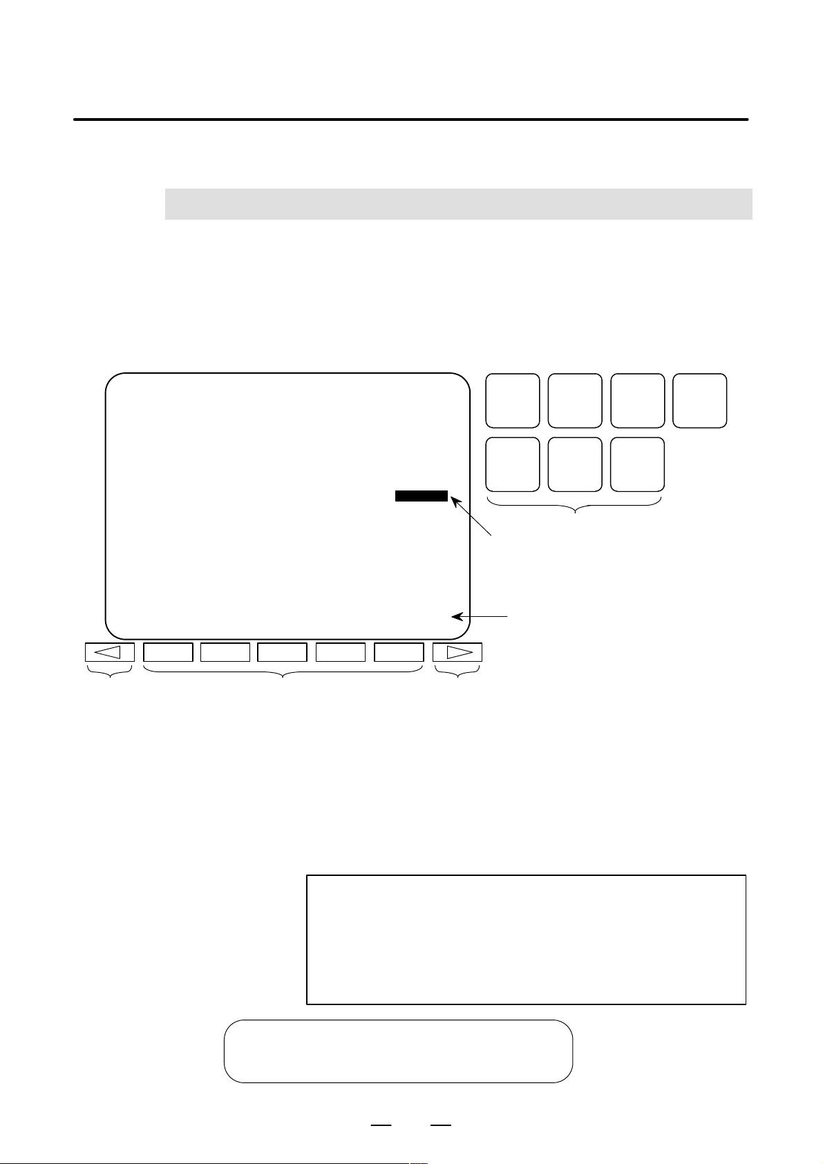
Follow the procedure below to display parameters.
(1) Press the <SYSTEM> function key on the MDI as many times as
required, or alternatively, press the <SYSTEM> function key once,
then the [P ARAM] section display soft key. The parameter screen is
then selected.
PARAMETER (FEEDRATE) O0001 N12345
1401 RDR JZR RF0 LRP RPD
0 0 0 0 0 0 0 0
1402 DLF HFC
0 0 0 0 0 0 0 0
1410 DRY RUN FEEDRATE 10000
1411 INIT.CUTTING F 0
1420 RAPID FEEDRATE X 15000
Y 15000
Z 15000
>
MEM STRT MTN FIN *** 10:02:35
[PARAM] [DGNOS] [ PMC ] [SYSTEM] [(OPRT)]
Return menu key Soft key Continuous menu key
POS PROG
SYSTEM MESSAGE GRAPH
Cursor
(2) The parameter screen consists of multiple pages. Use step (a) or (b)
to display the page that contains the parameter you want to display.
(a) Use the page select key or the cursor move keys to display the de-
sired page.
(b) Enter the data number of the parameter you want to display from
the keyboard, then press the [NO.SRH] soft key. The parameter
page containing the specified data number appears with the cursor positioned at the data number. (The data is displayed in reverse video.)
Function key
Soft key display
(section select)
OFFSET
SETTING
CUSTOM
NOTE
If key entry is started with the section select soft keys
displayed, they are replaced automatically by operation
select soft keys including [NO.SRH]. Pressing the [(OPRT)]
soft key can also cause the operation select keys to be
displayed.
>
MEM STRT MTN FIN *** 10:02:34
[NO.SRH] [ ON:1 ] [ OFF:0 ] [+INPUT] [INPUT ]
1
Data entered from
←
the keyboard
Soft key display
←
(section select)
Page 8

2. SETTING PARAMETERS FROM MDI
SETTING P ARAMETERS FROM MDI
2
Follow the procedure below to set parameters.
(1) Place the NC in the MDI mode or the emergency stop state.
(2) Follow the substeps below to enable writing of parameters.
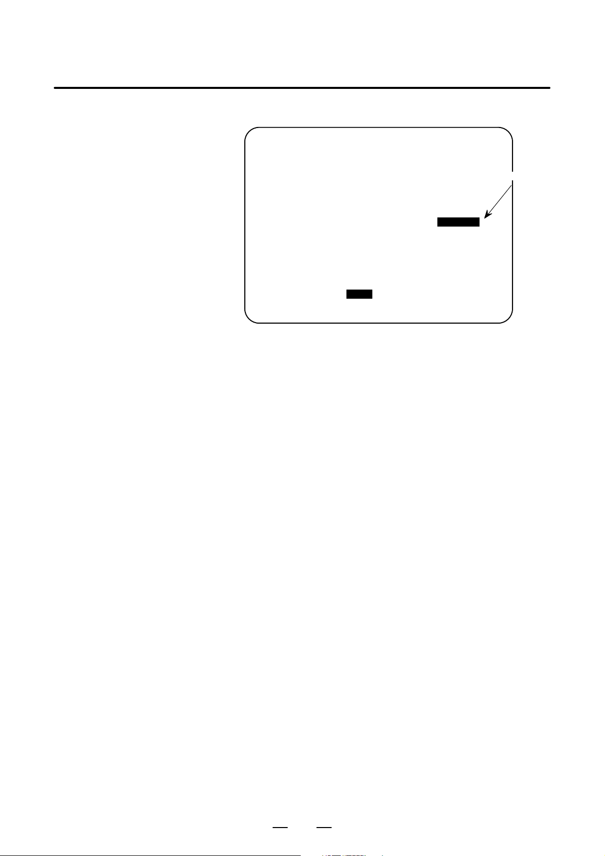
SETTING (HANDY) O0001 N00010
B–63510EN/01
1. To display the setting screen, press the <OFFSET/SETTING>
function key as many times as required, or alternatively press the
<OFFSET/SETTING> function key once, then the [SETTING]
section select soft key. The first page of the setting screen appears.
2. Position the cursor on “PARAMETER WRITE” using the cursor
move keys.
PARAMETER WRITE = (0:DISABLE 1:ENABLE)
TV CHECK = 0 (0:OFF 1:ON)
PUNCH CODE = 0 (0:EIA 1:ISO)
INPUT UNIT = 0 (0:MM 1:INCH)
I/O CHANNEL = 0 (0–2:CHANNEL NO.)
3. Press the [(OPRT)] soft key to display operation select soft keys.
>
MDI STOP *** *** *** 10:03:02
[NO.SRH] [ ON:1 ] [ OFF:0 ] [+INPUT] [INPUT]
4. To set “PARAMETER WRITE=” to 1, press the ON:1 soft key,
or alternatively enter 1 and press the [INPUT] soft key . From now
on, the parameters can be set. At the same time an alarm condition (P/S100 PARAMETER WRITE ENABLE) occurs in the
CNC.
(3) T o display the parameter screen, press the <SYSTEM> function key
as many times as required, or alternatively press the <SYSTEM>
function key once, then the [PARAM] section select soft key.
(See “1. Displaying Parameters.”)
(4) Display the page containing the parameter you want to set, and
position the cursor on the parameter. (See “1. Displaying
Parameters.”)
0
← Soft key display
(section select)
(5) Enter data, then press the [INPUT] soft key. The parameter indicated
by the cursor is set to the entered data.
2
Page 9
B–63510EN/01
2. SETTING PARAMETERS FROM MDI
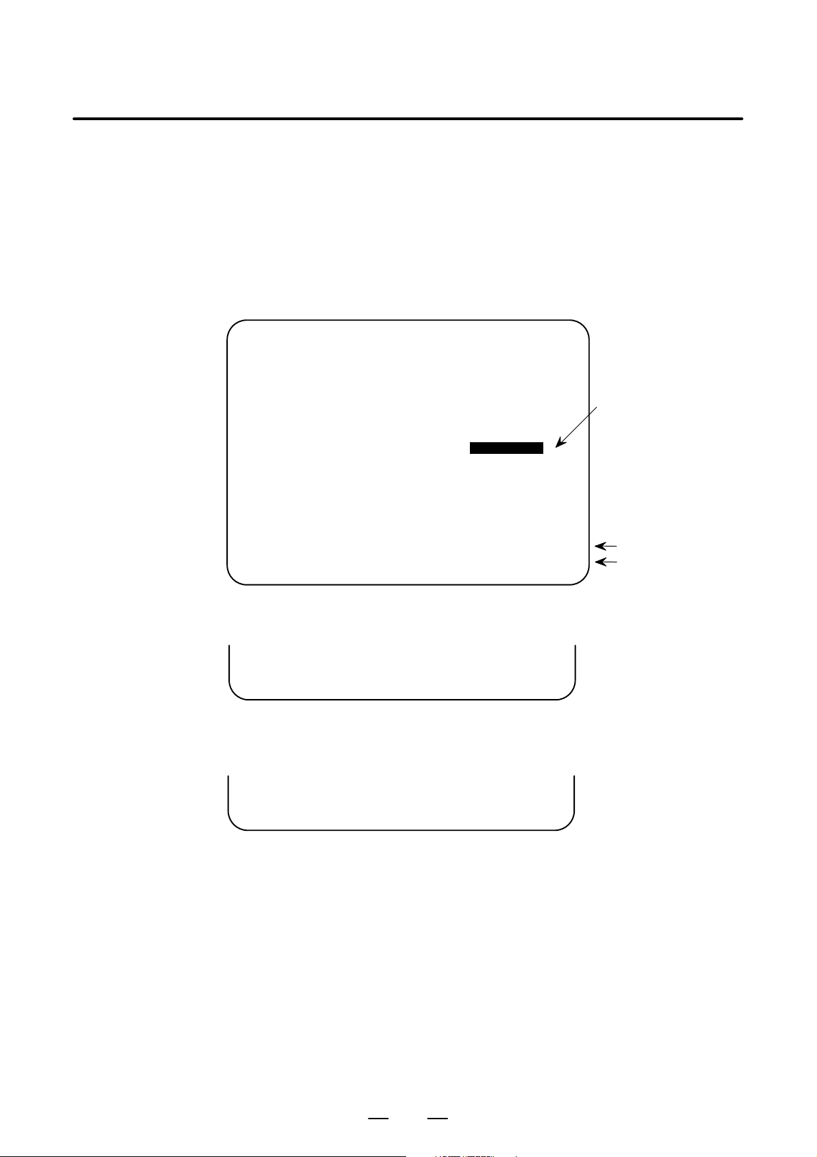
[Example] 12000 [INPUT]
PARAMETER (FEEDRATE) O0001 N00010
1401 RDR JZR RPD
00000000
1402 JRV
00000000
1410 DRY RUN FEEDRATE
1412 0
1420 RAPID FEEDRATEX 15000
Y 15000
Z 15000
>
MDI STOP *** *** ALM 10:03:10
[NO.SRH] [ ON:1 ] [ OFF:0 ] [+INPUT] [INPUT]
12000
Cursor
Data can be entered continuously for parameters, starting at the selected
parameter, by separating each data item with a semicolon (;).
[Example] Entering 10;20;30;40 and pressing the INPUT key assigns values 10, 20,
30, and 40 to parameters in order starting at the parameter indicatedby the
cursor.
(6) Repeat steps (4) and (5) as required.
(7) If parameter setting is complete, set “PARAMETER WRITE=” to 0
on the setting screen to disable further parameter setting.
(8) Reset the NC to release the alarm condition (P/S100).
If an alarm condition (P/S000 PLEASE TURN OFF POWER) occurs
in the NC, turn it off before continuing operation.
3
Page 10

3. INPUTTING AND OUTPUTTING PARAMETERS THROUGH THE READER/PUNCHER INTERFACE
INPUTTING AND OUTPUTTING PARAMETERS THROUGH THE
READER/PUNCHER INTERF ACE
3
This section explains the parameter input/output procedures for
input/output devices connected to the reader/puncher interface.
The following description assumes the input/output devices are ready for
input/output. It also assumes parameters peculiar to the input/output
devices, such as the baud rate and the number of stop bits, have been set
in advance.
B–63510EN/01
4
Page 11
B–63510EN/01
3. INPUTTING AND OUTPUTTING PARAMETERS THROUGH
THE READER/PUNCHER INTERFACE
3.1
OUTPUTTING PARAMETERS THROUGH THE READER/PUNCHER INTERFACE
PARAMETER (FEEDRATE) O0001 N00010
1401 RDR JZR RPD
1402 JRV
1410 DRY RUN FEEDRATE
1412 0
1420 RAPID FEEDRATEX 15000
>
MDI STOP *** *** ALM 10:03:10
[ ] [READ] [PUNCH] [ ] [ ]
(1) Select the EDIT mode or set to Emergency stop.
(2) T o select the parameter screen, press the <SYSTEM> function key as
many times as required, or alternatively press the <SYSTEM>
function key once, then the [PARAM] section select soft key.
(3) Press the [(OPRT)] soft key to display operation select soft keys, then
press the forward menu key located at the right–hand side of the soft
keys to display another set of operation select keys including
[PUNCH].
00000000
00000000
12000
Y 15000
Z 15000
Cursor
State display
Soft key display
(operation select)
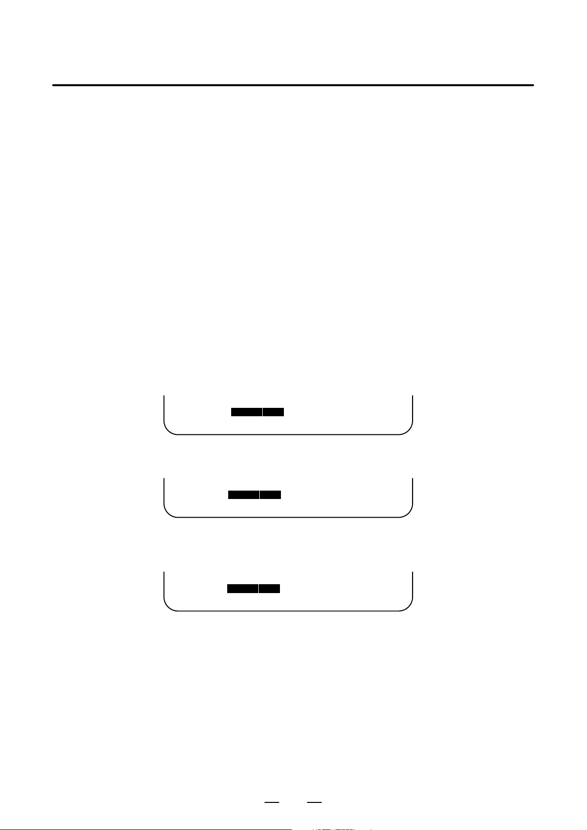
(4) Pressing the [PUNCH] soft key changes the soft key display as
shown below:
>
EDIT STOP *** *** *** 10:35:03
[ ] [ ] [ ] [CANCEL] [ EXEC ]
(5) Press the [EXEC] soft key to start parameter output. When
parameters are being output, “OUTPUT” blinks in the state display
field on the lower part of the screen.
>
EDIT STOP *** *** *** 10:35:04 OUTPUT
[ ] [ ] [ ] [CANCEL] [ EXEC ]
(6) When parameter output terminates, “OUTPUT” stops blinking. Press
the <RESET> key to interrupt parameter output.
← OUTPUT blinking
5
Page 12
3. INPUTTING AND OUTPUTTING PARAMETERS THROUGH
THE READER/PUNCHER INTERFACE
B–63510EN/01
3.2
INPUTTING PARAMETERS THROUGH THE READER/PUNCHER INTERFACE
(1) Place the NC in the emergency stop state.
(2) Enable parameter writing.
1. To display the setting screen, press the <OFFSET/SETTING>
function key as many times as required, or alternatively press the
<OFFSET/SETTING> function key once, then the [SETTING]
section select soft key. The first page of the setting screen appears.
2. Position the cursor on “PARAMETER WRITE” using the cursor
move keys.
3. Press the [(OPRT)] soft key to display operation select soft keys.
4. To set “PARAMETER WRITE=” to 1, press the ON:1 soft key,
or alternatively enter 1, then press the [INPUT] soft key. From
now on, parameters can be set. At the same time an alarm condition (P/S100 PARAMETER WRITE ENABLE) occurs in the
NC.
(3) T o select the parameter screen, press the <SYSTEM> function key as
many times as required, or alternatively press the <SYSTEM> key
once, then [PARAM] soft key.
(4) Press the [(OPRT)] soft key to display operation select keys, then
press the forward menu key located at the right–hand side of the soft
keys to display another set of operation select soft keys including
[READ].
>
EDIT STOP ALM 10:37:30
[ ] [ READ ] [PUNCH] [ ] [ ]
–EMG– ALM
(5) Pressing the [READ] soft key changes the soft key display as shown
below:
>
EDIT STOP ALM 10:37:30
[ ] [ ] [ ] [CANCEL] [ EXEC ]
–EMG– ALM
(6) Press the [EXEC] soft key to start inputting parameters from the
input/output device. When parameters are being input, “INPUT”
blinks in the state display field on the lower part of the screen.
>
EDIT STOP ALM 10:37:30 INPUT
[ ] [ ] [ ] [CANCEL] [ EXEC ]
–EMG– ALM
(7) When parameter input terminates, “INPUT” stops blinking. Press the
<RESET> key to interrupt parameter input.
(8) When parameter read terminates, “INPUT” stops blinking, and an
alarm condition (P/S000) occurs in the NC. Turn it off before
continuing operation.
← State display
← Soft key display
← INPUT blinking
6
Page 13

B–63510EN/01
4
DESCRIPTION OF PARAMETERS
Parameters are classified by data type as follows:
Table 4 Data Types and Valid Data Ranges of Parameters
Data type Valid data range Remarks
Bit
Bit axis
Byte
Byte axis
Word
Word axis
2–word
2–word axis
0 or 1
–128 to 127 In some parameters, signs are
–128 to 127
0 to 255
–32768 to 32767 In some parameters, signs are
–32768 to 32767
0 to 65535
–99999999 to 99999999
4. DESCRIPTION OF PARAMETERS
In some parameters, signs are
ignored.
In some parameters, signs are
ignored.
[Example]
0000
Data No.
1023 Servo axis number of a specific axis
Data No.
NOTE
1 For the bit type and bit axis type parameters, a single data
number is assigned to 8 bits. Each bit has a different
meaning.
2 The axis type allows data to be set separately for each
control axis.
3 The valid data range for each data type indicates a general
range. The range varies according to the parameters. For
the valid data range of a specific parameter, see the
explanation of the parameter.
(1) Notation of bit type and bit axis type parameters
#7
#6 #5
SEQ
#4 #3 #2
Data #0 to #7 are bit positions.
INI
#1
ISO
(2) Notation of parameters other than bit type and bit axis type
Data.
#0
TVC
7
Page 14

4. DESCRIPTION OF PARAMETERS
B–63510EN/01
NOTE
1 The bits left blank in 4. DESCRIPTION OF PARAMETERS
and parameter numbers that appear on the display but are
not found in the parameter list are reserved for future
expansion. They must always be 0.
2 Parameters having different meanings between the T series
and M series and parameters that are valid only for the T or
M series are indicated in two levels as shown below.
Parameters left blank are unavailable.
Example1
Parameter 5010 has different meanings for the T series
and M series.
5010
T ool nose radius compensation ...
T ool compensation C ...
T series
M series
Example2
DPI is a parameter common to the M and T series, but GSB
and GSC are parameters valid only for the T series.
#7 #6 #0
3401
GSC GSB DPI
DPI
T series
M series
Example3
The following parameter is provided only for the M series.
1450
F1 digit feed ...
T series
M series
8
Page 15

B–63510EN/01
4. DESCRIPTION OF PARAMETERS
4.1
P ARAMETERS OF SETTING
[Data type] Bit
#7
0000
#6 #5
SEQ
#4 #3 #2
Setting entry is acceptable.
TVC TV check
0 : Not performed
1 : Performed
ISO Code used for data output
0 : EIA code
1 : ISO code
INI Unit of input
0 : In mm
1 : In inches
SEQ Automatic insertion of sequence numbers
0: Not performed
1: Performed
When a program is prepared by using MDI keys in the part program
storage and edit mode, a sequence number can automatically be assigned
to each block in set increments. Set the increment to parameter 3216.
INI
#1
ISO
#0
TVC
0001
Setting entry is acceptable.
[Data type] Bit
FCV Tape format
0: Standard format
1: FS10/11 format
#7
#6 #5 #4 #3 #2 #1
FCV
#0
NOTE
1 Programs created in the Series 15 tape format can be
used for operation on the following functions:
1 Subprogram call M98
2 Thread cutting with equal leads G32 (T series)
3 Canned cycle G90, G92, G94 (T series)
4 Multiple repetitive canned cycle G71 to G76 (T series)
5 Drilling canned cycle G73, G74, G76, G80 to G89 (M
series)
6 Cutter compensation C (M series)
2 When the tape format used in the FS10/11 is used for this
CNC, some limits may add. Refer to the Series 0i–TA or
Series 0i–MA OPERATOR’S MANUAL (B–63504EN or
B–63514EN).
9
Page 16

4. DESCRIPTION OF PARAMETERS
B–63510EN/01
0002
Setting entry is acceptable.
[Data type] Bit
SJZ Manual reference position si performed as follows:
0 : When no reference position has been set, reference position return is
1 : Reference position return is performed using deceleration dogs at all
#7
SJZ
#6 #5 #4 #3 #2 #1 #0
performed using deceleration dogs. When a reference position is
already set, reference position return is performed using rapid traverse
and deceleration dogs are ignored.
times.
NOTE
SJZ is enabled when bit 3 (HJZ) of parameter No.1005 is
set to 1. When a reference position is set without a dog,
(i.e. when bit 1 (DLZ) of parameter No.1002 is set to 1 or
bit 1 (DLZx) of parameter No.1005 is set to 1) reference
position return after reference position setting is
performed using rapid traverse at all times, regardless of
the setting of SJZ.
0012
Setting entry is acceptable.
[Data type] Bit axis
MIRx Mirror image for each axis
0 : Mirror image is off.
1 : Mirror image is on.
0020 I/O CHANNEL: Selection of an input/output device
Setting entry is acceptable.
[Data type] Byte
[Valid data range] 0 to 2
The CNC provides the following interfaces for data transfer to and from
the host computer and external input/output devices:
This parameter selects the interface used to transfer data to and from an
input/output device.
#7
#6 #5 #4 #3 #2 #1 #0
F Input/output device interface (RS–232C serial port 1, 2)
MIRx
Setting Description
0, 1 RS–232C serial port 1
2 RS–232C serial port 2
10
Page 17
B–63510EN/01
4. DESCRIPTION OF PARAMETERS
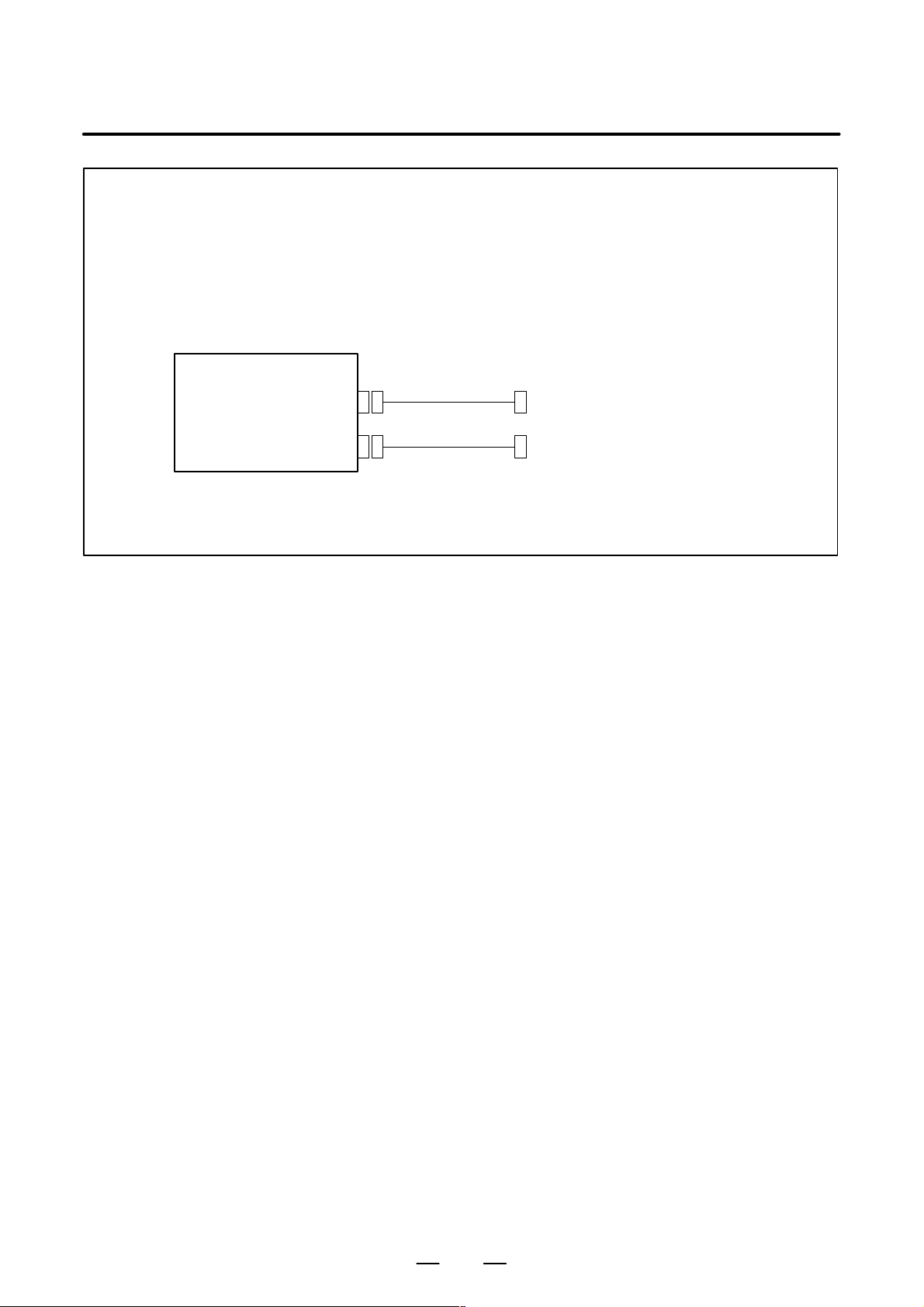
NOTE
1 An input/output device can also be selected using the setting screen. Usually, the setting screen
is used.
2 The specifications (such as the baud rate and the number of stop bits) of the input/output
devices to be connected must be set in the corresponding parameters for each interface
beforehand. (See Section 4.2.) I/O CHANNEL = 0 and I/O CHANNEL = 1 represent input/output
devices connected to RS–232C serial port 1. Separate parameters for the baud rate, stop bits,
and other specifications are provided for each channel.
I/O card
RS–232–C serial port 1
R232–1(JD5A)
RS–232–C serial port 2
R232–2(JD5B)
I/O CHANNEL=0, 1
(Channel 1)
I/O CHANNEL=2
(Channel 2)
RS-232-C I/O device
RS-232-C I/O device
3 The input/output unit interface may be referred to as the reader/punch interface.
RS–232C serial port 1 and RS–232C serial port 2 are also referred to as channel 1 and channel
2, respectively.
11
Page 18

4. DESCRIPTION OF PARAMETERS
B–63510EN/01
4.2
PARAMETERS OF READER/PUNCHER INTERFACE
0020
Specify a channel for an input/output device.
I/ O CHANNEL
=0 : Channel1
=1 : Channel1
=2 : Channel2
I/O CHANNEL
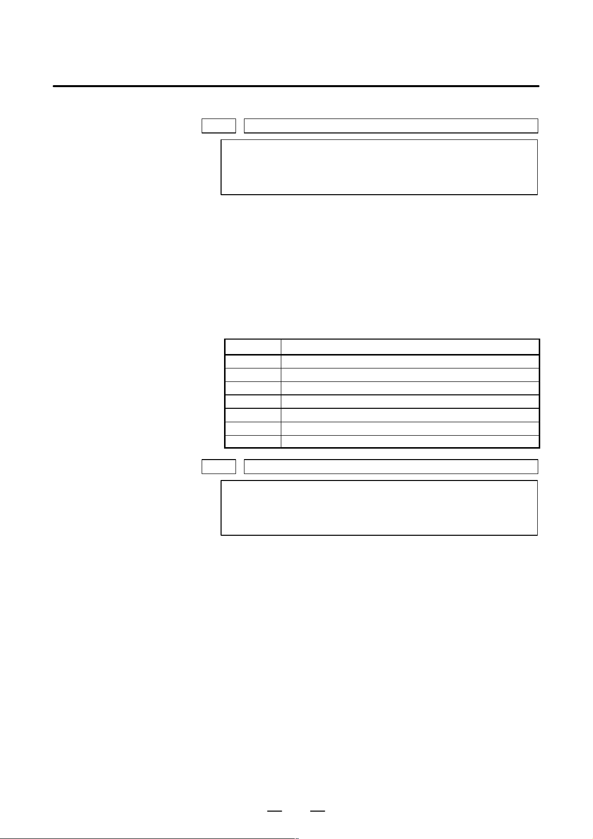
This section describes the parameters that must be set to input data
(programs, parameters, etc.) from and output it to external I/O devices
through an I/O device interface (RS–232C serial port).
The setting parameter I/O CHANNEL can be used to select the channel
to which the I/O device to be used is connected from the two channels,
RS–232C serial port 1 and RS–232C serial port 2 interface. Make sure
that the specifications (number of the I/O device, baud rate, number of
stop bits, and other parameters) of the I/O device to be connected to each
channel is set in the parameter corresponding to the channel in advance.
For channel 1, two combinations of parameters to specify the input/output
device data are provided.
The following shows the interrelation between the input/output device
interface parameters for the channels.
Input/output channel number (parameter No.0020)
↓
Stop bit and other data
Number specified for the input/
output device
Baud rate
Stop bit and other data
Number specified for the input/
output device
Baud rate
I/O CHANNEL=0
(channel 1)
I/O CHANNEL=1
(channel 1)
0101
0102
0103
0111
0112
0113
0121
I/O CHANNEL=2
(channel 2)
Fig.4.2 I/O Device Interface Settings
0122
0123
Stop bit and other data
Number specified for the input/
output device
Baud rate
12
Page 19

B–63510EN/01
4.2.1
Parameters Common to all Channels
[Data type] Bit
4. DESCRIPTION OF PARAMETERS
#7
ENS0100
#6
IOP
#5
ND3
#4 #3
NCR
#2 #1
CTV
#0
Setting entry is acceptable.
CTV: Character counting for TV check in the comment section of a program.
0 : Performed
1 : Not performed
NCR Output of the end of block (EOB) in ISO code
0 : LF, CR, CR are output.
1 : Only LF is output.
ND3 In DNC operation, a program is:
0 : Read block by block. (A DC3 code is output for each block.)
1 : Read continuously until the buffer becomes full. (A DC3 code is
output when the buffer becomes full.)
NOTE
In general, reading is performed more efficiently when ND3
set to 1. This specification reduces the number of buffering
interruptions caused by reading of a series of blocks
specifying short movements. This in turn reduces the
effective cycle time.
IOP Specifies how to stop program input/output operations.
0 : An NC reset can stop program input/output operations.
1 : Only the [STOP] soft key can stop program input/output operations.
(An reset cannot stop program input/output operations.)
ENS Action taken when a NULL code is found during read of EIA code
0 : An alarm is generated.
1 : The NULL code is ignored.
13
Page 20

4. DESCRIPTION OF PARAMETERS
4.2.2
Parameters of Channel 1 (I/O CHANNEL=0)
[Data type] Bit type
SB2 The number of stop bits
ASI Code used at data input
NFD Feed before and after the data at data output
#7
NFD0101
#6 #5 #4 #3
ASI
#2 #1 #0
0 : 1
1 : 2
0 : EIA or ISO code (automatically distinguished)
1 : ASCII code
0 : Output
1 : Not output
NOTE
When input/output devices other than the FANUC PPR
are used, set NFD to 1.
B–63510EN/01
SB2
0102 Number specified for the input/ou tp ut device (when the I/O CHANNEL is set to 0)
[Data type] Byte
Set the number specified for the input/output device used when the I/O
CHANNEL is set to 0, with one of the set values listed in T able 4.2.2 (a).
Set value Input/output device
0103 Baud rate (when the I/O CHANNEL is set to 0)
[Data type] Byte
Set baud rate of the input/output device used when the I/O CHANNEL is
set to 0, with a set value in Table 4.2.2 (b).
Table 4.2.2 (a) Set value and Input/Output Device
0 RS–232–C (Used control codes DC1 to DC4)
1 FANUC CASSETTE ADAPTOR 1 (FANUC CASSETTE B1/ B2)
2 FANUC CASSETTE ADAPTOR 3 (FANUC CASSETTE F1)
3 FANUC PROGRAM FILE Mate, FANUC F A Card Adaptor
FANUC FLOPPY CASSETTE ADAPT OR, FANUC Handy File
FANUC SYSTEM P-MODEL H
4 RS–232–C (Not used control codes DC1 to DC4)
5 Portable tape reader
6 FANUC PPR
FANUC SYSTEM P-MODEL G, FANUC SYSTEM P-MODEL H
Table 4.2.2 (b)
Set value Baud rate (bps)
1
2
3
4
5
6
50
100
110
150
200
300
14
Set value Baud rate (bps)
7
8
9
10
11
12
600
1200
2400
4800
9600
19200
Page 21

B–63510EN/01
4.2.3
Parameters of Channel 1 (I/O CHANNEL=1)
[Data type] Bit
These parameters are used when I/O CHANNEL is set to 1. The meanings
of the bits are the same as for parameter 0101.
0112 Number specified for the input/output device (when I/O CHANNEL is set to 1)
[Data type] Byte
Set the number specified for the input/output device used when the I/O
CHANNEL is set to 1, with one of the set values listed in Table 4.2 (a).
0113 Baud rate (when I/O CHNNEL is set to 1)
[Data type] Byte
Set the baud rate of the input/output device used when I/O CHANNEL is
set to 1, with a value in Table 4.2 (b).
4. DESCRIPTION OF PARAMETERS
#7
NFD0111
#6 #5 #4 #3
ASI
#2 #1 #0
SB2
4.2.4
Parameters of Channel 2 (I/O CHANNEL=2)
[Data type] Bit
These parameters are used when I/O CHANNEL is set to 2. The meanings
of the bits are the same as for parameter 0101.
0122 Number specified for the input/output device (when I/O CHANNEL is set to 2)
[Data type] Byte
Set the number specified for the input/output device used when I/O
CHANNEL is set to 2, with a value in Table 4.2 (a).
0123 Baud rate (when the I/O CHANNEL is set to 2)
[Data type] Byte
Set the baud rate of the input/output device used when I/O CHANNEL is
set to 2, with a value in Table 4.2 (b).
#7
NFD0121
#6 #5 #4 #3
ASI
#2 #1 #0
SB2
15
Page 22

4. DESCRIPTION OF PARAMETERS
4.3
P ARAMETERS OF POWER MOTION MANAGER
[Data type] Bit
0960
SLV When the power mate CNC manager is selected, the screen displays:
#7
#6 #5 #4
SPE
#3
PMN#2MD2
0 : One slave.
1 : Up to four slaves with the screen divided into four.
B–63510EN/01
#1
MD1
#0
SLV
MD1,MD2
These parameters set a slave parameter input/output destination.
MD2 MD1 Input/output destination
0 0 Part program storage
0 1 Unused
In either case, slave parameters are output in program format.
PMN The power mate CNC manager function is:
0 : Enabled.
1 : Disabled. (Communication with slaves is not performed.)
SPE The slave parameters set by the PowerMate CNC manager feature are:
0 : Always enabled.
1 : Enabled or disabled according to the setting of “W riting parameters.”
16
Page 23

B–63510EN/01
4.4
P ARAMETERS OF AXIS CONTROL/ INCREMENT SYSTEM
[Data type] Bit
4. DESCRIPTION OF PARAMETERS
#7
1001
#6 #5 #4 #3 #2 #1 #0
NOTE
When this parameter is set, the power must be turned off
before operation is continued.
INM Least command increment on the linear axis
0 : In mm (metric system machine)
1 : In inches (inch system machine)
INM
1002
#7
IDG
#6 #5 #4
XIK
XIK
#3
AZR
#2
SFD
DLZ
DLZ
[Data type] Bit
JAX Number of axes controlled simultaneously in manual continuous feed,
manual rapid traverse and manual reference position return
0 : 1 axis
1 : 3 axes
DLZ Function setting the reference position without dog
0 : Disabled
1 : Enabled
NOTE
This function can be specified for each axis by DLZx, bit 1
of parameter No.1005.
SFD The function for shifting the reference position is
0: Not used.
1: Used.
AZR When no reference position is set, the G28 command causes:
0: Reference position return using deceleration dogs (as during manual
reference position return) to be exected.
1: P/S alarm No.090 to be issued.
#1
#0
JAX
JAXIDG
NOTE
When reference position return without dogs is specified,
(when bit 1 (DLZ) of parameter No.1002 is set to 1 or bit 1
(DLZx) of parameter No.1005 is set to 1) the G28 command
specified before a reference position is set causes P/S
alarm No.090 to be issued, regardless of the setting of AZR.
17
Page 24

4. DESCRIPTION OF PARAMETERS
XIK When LRP, bit 1 of parameter No.1401, is set to 0, namely, when
IDG When the reference position is set without dogs, automatic setting of the
B–63510EN/01
positioning is performed using non–linear type positioning, if an
interlock is applied to the machine along one of axes in positioning,
0: The machine stops moving along the axis for which the interlock is
applied and continues to move along the other axes.
1: The machine stops moving along all the axes.
IDGx parameter (bit 0 of parameter No.1012) to prevent the reference
position from being set again is:
0 : Not performed.
1 : Performed.
[Data type] Bit
ISC The least input increment and least command increment are set.
IPR Whether the least input increment for each axis is set to a value 10 times as
large as the least command increment is specified, in increment systems
of IS–B or IS–C at setting mm.
0: The least input increment is not set to a value 10 times as larg as the
1: The least input increment is set to a value 10 times as large as the least
If IPR is set to 1, the least input increment is set as follows:
#7
IPR1004
#6 #5 #4 #3 #2 #1
ISC
#0
NOTE
When this parameter is set, the power must be turned off
before operation is continued.
ISC Least input increment and least command increment Symbol
0 0.001 mm, 0.001 deg, or 0.0001 inch IS–B
1 0.0001 mm, 0.0001 deg, or 0.00001 inch IS–C
least command increment.
command increment.
Input increment Least input increment
IS–B 0.01 mm, 0.01 deg, or 0.0001 inch
IS–C 0.001 mm, 0.001 deg, or 0.00001 inch
NOTE
Inputs in inches are multiplied by 10.
#7
1005
#6 #5
EDMx
EDMx
#4
EDPx
EDPx#3HJZx
#2 #1
DLZx
DLZx
[Data type] Bit axis
ZRNx When a command specifying the movement except for G28 is issued in
automatic operation (MEM, RMT, or MDI) and when a return to the
reference position has not been performed since the power was turned on
0 : An alarm is generated (P/S alarm 224).
1 : An alarm is not generated.
18
#0
ZRNx
ZRNx
Page 25

B–63510EN/01
4. DESCRIPTION OF PARAMETERS
NOTE
The state in which the reference position has not been
established refers to that state in which reference position
return has not been performed after power–on when an
absolute position detector is not being used, or that state in
which the association of the machine position with the position
detected with the absolute position detector has not been
completed (see the descriptio n of bit 4 (APZx) of parameter
No. 1815) when an absolute position detector is being used.
DLZx Function for setting the reference position without dogs
0 : Disabled
1 : Enabled
NOTE
When DLZ of parameter No.1002 is 0, DLZx is enabled.
When DLZ of parameter No.1002 is 1, DLZx is disabled, and
the function for setting the reference position without dogs
is enabled for all axes.
HJZx When a reference position is already set:
0 : Manual reference position return is performed with deceleration sogs.
1 : Manual reference position return is performed using rapid traverse
without deceleration dogs, or manual reference position return is
performed with deceleration dogs, depending on the setting of bit 7
(SJZ) of parameter No.0002.
NOTE
When reference position return without dogs is specified,
(when bit 1 (DLZ) of parameter No.1002 is set to 1 or bit
(DLZx) of parameter No.1005 is set to 1) reference position
return after a reference position is set is performed using
rapid traverse, regardless of the setting of HJZ.
EDPx External deceleration signal in the positive direction for each axis
0 : Valid only for rapid traverse
1 : Valid for rapid traverse and cutting feed
EDMx External deceleration signal in the negative direction for each axis
0 : Valid only for rapid traverse
1 : Valid for rapid traverse and cutting feed
#7
1006
#6 #5
ZMIx
ZMIx
#4 #3
DIAx
#2 #1
ROSx
ROSx
#0
ROTx
ROTx
NOTE
When this parameter is set, the power must be turned off
before operation is continued.
[Data type] Bit axis
19
Page 26

4. DESCRIPTION OF PARAMETERS
ROTx, ROSx Setting linear or rotation axis.
B–63510EN/01
ROSx ROTx Meaning
0 0 Linear axis
(1) Inch/metric conversion is done.
(2) All coordinate values are linear axis type.
(3) Stored pitch error compensation is linear axis type
(Refer to parameter No.3624)
0 1 Rotation axis (A type)
(1) Inch/metric conversion is not done.
(2) Machine coordinate values are rounded in 0 to 360_.
Absolute coordinate values are rounded or not rounded
by parameter No.1008#0(ROAx) and #2(RRLx).
(3) Stored pitch error compensation is the rotation type.
(Refer to parameter No.3624)
(4) Automatic reference position return (G28, G30) is done
in the reference position return direction and the move
amount does not exceed one rotation.
1 0 Setting is invalid (unused)
1 1 Rotation axis (B type)
(1) Inch/metric conversion, absolute coordinate values and
relative coordinate values are not done.
(2) Machine coordinate values, absolute coordinate values
and relative coordinate values are linear axis type. (Is
not rounded in 0 to 360_).
(3) Stored pitch error compensation is linear axis type (Re-
fer to parameter No.3624)
(4) Cannot be used with the ratation axis roll over function
and the index table indexing fanction (M series)
DIAx Either a diameter or radius is set to be used for specifying the amount of
travel on each axis.
0 : Radius
1 : Diameter
ZMIx The direction of reference position return.
0 : Positive direction
1 : Negative direction
NOTE
The direction of the initial backlash, which occurs when
power is switched on, is opposite to the direction of a
reference position return.
#7
1008
#6 #5 #4 #3 #2
RRLx#1RABx#0ROAx
NOTE
When this parameter is set, the power must be turned off
before operation is continued.
[Data type] Bit axis
ROAx The roll–over function of a rotation axis is
0 : Invalid
1 : Valid
20
Page 27

B–63510EN/01
4. DESCRIPTION OF PARAMETERS
NOTE
ROAx specifies the function only for a rotation axis (for which
ROTx, #0 of parameter No.1006, is set to 1)
RABx In the absolute commands, the axis rotates in the direction
0 : In which the distance to the target is shorter.
1 : Specified by the sign of command value.
NOTE
RABx is valid only when ROAx is 1.
RRLx Relative coordinates are
0 : Not rounded by the amount of the shift per one rotation
1 : Rounded by the amount of the shift per one rotation
NOTE
1 RRLx is valid only when ROAx is 1.
2 Assign the amount of the shift per one rotation in parameter
No.1260.
Examples
1010 Number of CNC–controlled axes
NOTE
When this parameter is set, the power must be turned off
before operation is continued.
[Data type] Byte
[Valid data range] 1, 2, 3, ..., the number of controlled axes
Set the maximum number of axes that can be controlled by the CNC.
Suppose that the first axis is the X axis, and the second and subsequent
axes are the Y, Z, and A axes in that order, and that they are controlled as
follows:
X, Y, and Z axes: Controlled by the CNC and PMC
A axis: Controlled by the PMC
Then set this parameter to 3 (total 3: 1st to 3rd axes)
21
Page 28

4. DESCRIPTION OF PARAMETERS
B–63510EN/01
#7
1012
#6 #5 #4 #3 #2 #1 #0
[Data type] Bit axis
IDGx The function for setting the reference position again, without dogs, is:
0 : Not inhibited.
1 : Inhibited.
NOTE
1 IDGx is enabled when the IDG parameter (bit 7 of parameter
No.1002) is 1.
2 When the function for setting the reference position, without
dogs, is used, and the reference position is lost for some
reason, an alarm requesting reference position return
(No.300) is generated when the power is next turned on. If
the operator performs reference position return, as a result
of mistakenly identifying the alarm as that requesting the
operator to perform a normal reference position return, an
invalid reference position may be set. To prevent such an
operator error, the IDGx parameter is provided to prevent the
reference position from being set again without dogs.
(1) If the IDG parameter (bit 7 of parameter No.1002) is set
to 1, the IDGx parameter (bit 0 of parameter No.1012)
is automatically set to 1 when the reference position is
set using the function for setting the reference position
without dogs. This prevents the reference position from
being set again without dogs.
(2) Once the reference position is prevented from being set
for an axis again, without dogs, any attempt to set the
reference position for the axis without dogs results in the
output of an alarm (No.090).
(3) When the reference position must be set again without
dogs, set IDGx to 0 before setting the reference position.
IDGx
22
Page 29

B–63510EN/01
1020 Program axis name for each axis
[Data type] Byte axis
Set the program axis name for each controlled axis, using one of the values
listed in the following table:
Axis
name
X 88 U 85 A 65 E 69
Y 89 V 86 B 66
Z 90 W 87 C 67
NOTE
1 With the T series, when G code system A is used, neither U,
V, nor W can be used as an axis name. Only when G code
system B or C is used, U, V, and W can be used as axis
names.
2 The same axis name cannot be assigned to more than one
axis.
3 Address used by the secondary auxiliary function (address
B with the T series or, with the M series, the address
specified in parameter No.3460) cannot be used as an axis
name.
4 With the T series, when address C or A is used for direct
drawing dimension programming (when the CCR parameter
(bit 4 of parameter No.3405) is set to 1), addresses C or A
cannot be used as an axis name.
5 Only with the T series, address E can be used as an axis
name. Address E cannot be used with the M series. When
address E is used as an axis name, note the following:
– When G code system A is used, address E is always
assigned to an absolute command.
– When an equal–lead threading command (G32) is issued
in the FS10/11 command format, address E cannot be
used to specify the thread lead. Use address F to specify
the thread lead.
Setting
Axis
name
4. DESCRIPTION OF PARAMETERS
Setting
Axis
name
Setting
Axis
name
Setting
23
Page 30
4. DESCRIPTION OF PARAMETERS
1022 Setting of each axis in the basic coordinate system
[Data type] Byte axis
B–63510EN/01
NOTE
When this parameter is set, power must be turned off before
operation is continued.
To determine the following planes used for circular interpolation, cutter
compensation C (for the M series), tool nose radius compensation (for the
T series), etc., each control axis is set to one of the basic three axes X, Y,
and Z, or an axis parallel to the X, Y, or Z axis.
G17: Plane Xp–Yp
G18: Plane Zp–Xp
G19: Plane Yp–Zp
Only one axis can be set for each of the three basic axes X, Y, and Z, but
two or more parallel axes can be set.
Set value Meaning
0 Neither the basic three axes nor a parallel axis
1 X axis of the basic three axes
2 Y axis of the basic three axes
3 Z axis of the basic three axes
5 Axis parallel to the X axis
6 Axis parallel to the Y axis
7 Axis parallel to the Z axis
1023 Number of the servo axis for each axis
NOTE
When this parameter is set, power must be turned off before
operation is continued.
[Data type] Byte axis
[Valid data range] 1, 2, 3, ..., number of control axes
Set the servo axis for each control axis.
Usually set to same number as the control axis number.
The control axis number is the order number that is used for setting the
axis–type parameters or axis–type machine signals
24
Page 31

B–63510EN/01
4. DESCRIPTION OF PARAMETERS
4.5
P ARAMETERS OF COORDINATES
[Data type] Bit
1201
#7
WZR
#6 #5
AWK
AWK
#4 #3 #2
ZCL
ZCL
#1 #0
ZCL Local coordinate system when the manual reference position return is
performed
0 : The local coordinate system is not canceled.
1 : The local coordinate system is canceled.
AWK When the workpiece zero point offset value is changed
0 : The absolute position display changed when the next buf foring block
is performed.
1 : The absolute position display is changed immediately.
Changed value is valid ofter baffering the next block.
WZR Upon reset, the workpiece coordinate system is:
0 : Not returned to that specified with G54
1 : Returned to that specified with G54
#7
1202
#6 #5 #4
G52
#3
RLC
RLC
#2
G50
#1
EWS#0EWD
[Data type] Bit
EWD The shift direction of the workpiece coordinate system is:
0 : The direction specified by the external workpiece zero point offset
value
1 : In the opposite direction to that specified by the external workpiece
zero point offset value
X
XXX
EWD=0
Z
EXOFS
Z
EXOFS : External workpiece zero point offset value
EWD=1
–EXOFS
(Shifted workpiece
Z
coordinate system)
(Original workpiece
Z
coordinate system)
EWS Shift value of the workpiece coordinate system and external workpiece
zero point offset value are
0 : Stored in the separate memory areas.
1 : Stored in the same memory area, that is, the shift and the offset values
are the same.
G50 If the G50 command for setting a coordinate system (or the G92 command
in G command system B or C) is specified,
0 : G50 is executed and no alarm is issued.
1 : G50 is not executed and a P/S alarm (No. 010) is issued.
25
Page 32

4. DESCRIPTION OF PARAMETERS
RLC Local coordinate system is
G52 In local coordinate system setting (G52), a cutter compensation vector is:
1220 External workpiece zero point of fset value
[Data type] 2–word axis
[Unit of data]
B–63510EN/01
0 : Not cancelled by reset
1 : Cancelled by reset
0 : Not considered.
1 : Considered.
NOTE
Select a local coordinate system setting operation when
cutter compensation is applied, and when two or more
blocks specifying no movement exist prior to the
specification of G52, or when G52 is specified after cutter
compensation mode is canceled without eliminating the
offset vector.
Input increment IS–B IS–C Unit
Linear axis (input in mm) 0.001 0.0001
Linear axis (input in inches) 0.0001 0.00001 inch
Rotation axis 0.001 0.0001 deg
mm
[Valid data range] –99999999 to 99999999
This is one of the parameters that give the position of the origin of
workpiece coordinate system (G54 to G59). It gives an offset of the
workpiece origin common to all workpiece coordinate systems. In
general, the offset varies depending on the workpiece coordinate systems.
The value can be set from the PMC using the external data input function.
1221 Workpiece zero point offset value in workpiece coordinate system 1 (G54)
1222 W orkpiece zero point of fset value in workpiece coordinate system 2(G55)
1223 W orkpiece zero point of fset value in workpiece coordinate system 3(G56)
1224 Workpiece zero point offset value in workpiece coordinate system 4 (G57)
1225 Workpiece zero point offset value in workpiece coordinate system 5 (G58)
1226 Workpiece zero point offset value in workpiece coordinate system 6 (G59)
[Data type] 2–word axis
[Unit of data]
Input increment IS–B IS–C Unit
Linear axis (input in mm) 0.001 0.0001 mm
Linear axis (input in inches) 0.0001 0.00001 inch
Rotation axis 0.001 0.0001 deg
26
Page 33

B–63510EN/01
4. DESCRIPTION OF PARAMETERS
[Valid data range] –99999999 to 99999999
The workpiece zero point of fset values in workpiece coordinate systems 1
to 6 (G54 to G59) are set.
Workpiece coordinate system 1 (G54)
Workpiece coordinate system 2 (G55)
Workpiece zero point offset
Origin of machine coordinate system
NOTE
The workpiece origin offset can also be set using the
workpiece coordinate system screen.
1240
Coordinate value of the reference position on each axis in the machine
coordinate system
NOTE
When this parameter is set, power must be turned off before
operation is continued.
1241
1242
1243
Coordinate value of the second reference position on each axis in the machine
coordinate system
Coordinate value of the third reference position on each axis in the machine coordinate system
Coordinate value of the fourth reference position on each axis in the machine
coordinate system
[Data type] 2–word axis
[Unit of data]
Increment system IS–B IS–C Unit
Millimeter machine 0.001 0.0001
Inch machine 0.0001 0.00001
Rotation axis 0.001 0.0001
mm
inch
deg
27
Page 34

4. DESCRIPTION OF PARAMETERS
[Valid data range] –99999999 to 99999999
1260 Amount of a shift per one rotation of a rotation axis
[Data type] 2–word axis
[Unit of data]
[Valid data range] 1000 to 9999999
B–63510EN/01
Set the coordinate values of the reference positions in the machine
coordinate system.
NOTE
When this parameter is set, the power must be turned off
before operation is continued.
Increment system Unit of data Standard value
IS–B 0.001 deg 360000
IS–C 0.0001 deg 3600000
Set the amount of a shift per one rotaion of a rotaion axis.
28
Page 35

B–63510EN/01
4.6
4. DESCRIPTION OF PARAMETERS
P ARAMETERS OF STROKE CHECK
[Data type] Bit
1300
#7
BFA
#6
LZR
LZR
#5
RL3
#4 #3 #2
LMS
LMS
#1 #0
OUT
OUTBFA
OUT The area inside or outside of the stored stroke check 2 is set as an
inhibition area. (Setting by parameter 1322 or 1323)
0: Inside
1: Outside
LMS The EXLM signal for switching stored stroke check 1
0: Disabled
1: Enabled
NOTE
Stored stroke check 1 supports two pairs of parameters for
setting the prohibited area. The stored stroke limit switching
signal is used to enable either of the prohibited areas set with
these parameter pairs.
(1) Prohibited area I: Parameters No.1320 and No.1321
(2) Prohibited area II: Parameters No.1326 and No.1327
RL3 Stored stroke check 3 release signal RLSOT3 is
0: Disabled
1: Enabled
LZR Checking of stored stroke check 1 during the time from power–on to the
manual position reference return
0: The stroke check 1 is checked.
1: The stroke check 1 is not checked
NOTE
When an absolute position detector is used and a reference
position is already set upon power–up, stored stroke limit
check 1 is started immediately after power–up, regardless of
the setting.
BFA When a command that exceeds a stored stroke check is issued
0: An alarm is generated after the stroke check is exceeded.
1: An alarm is generated before the stroke check is exceeded.
NOTE
The tool stops at a point up to F/7500 mm short of or ahead
of the boundary.
(F: Feedrate when the tool reaches the boundary (mm/min))
#7
1310
#6 #5 #4 #3 #2 #1
[Data type] Bit axis
OT2x Whether stored stroke check 2 is checked for each axis is set.
0: Stored stroke check 2 is not checked.
1: Stored stroke check 2 is checked.
OT3x#0OT2x
OT2x
29
Page 36

4. DESCRIPTION OF PARAMETERS
OT3x Whether stored stroke check 3 is checked for each axis is set.
1320 Coordinate value I of stored stroke check 1 in the positive direction on each axis
1321 Coordinate value I of stored stroke check 1 in the negative direction on each axis
[Data type] 2–word axis
[Unit of data]
[Valid data range] –99999999 to 99999999
B–63510EN/01
0: Stored stroke check 3 is not checked.
1: Stored stroke check 3 is checked.
Increment system IS–B IS–C Unit
Millimeter machine 0.001 0.0001 mm
Inch machine 0.0001 0.00001 inch
Rotation axis 0.001 0.0001 deg
The coordinate values of stored stroke check 1 in the positive and negative
directions are setfor each axis in the machine coordinate system. The
outside area of the two checks set in the parameters is inhibited.
(Xp,Yp,Zp)
(Xm,Ym,Zm)
Set the machine coordinates of the
boundaries in the positive direction
(Xp, Yp, and Zp) using parameter No.
1320, and those of the boundaries in
the negative direction (Xm, Ym, and
Zm) using parameter No. 1321. The
prohibited area thus becomes the
hatched area in the figure on the left.
NOTE
1 For axes with diameter specification, a diameter value must
be set.
2 When the parameters are set as follows, the stroke becomes
infinite:
parameter 1320 < parameter 1321
For movement along the axis for which infinite stroke is set,
only increment commands are available. If an absolute
command is issued for this axis, the absolute register may
overflow, and normal movement will not result.
3 The prohibited area specified with these parameters is
invalid if bit 2 (LMS) of parameter No. 1300 is set to 1 and
stored stroke limit switching signal EXLM is set to 1. In such
a case, the settings of parameters No. 1326 and 1327 are
used, instead.
1322 Coordinate value of stored stroke check 2 in the positive direction on each axis
1323 Coordinate value of stored stroke check 2 in the negative direction on each axis
[Data type] 2–word axis
[Unit of data]
Increment system IS–B IS–C Unit
Millimeter machine 0.001 0.0001 mm
Inch machine 0.0001 0.00001 inch
Rotation axis 0.001 0.0001 deg
30
Page 37

B–63510EN/01
[Valid data range] –99999999 to 99999999
Set the coordinate values of stored stroke check 2 in the positive and
negative directions foreach axis in the machine coordinate system. OUT,
#0 of parameter 1300, sets either the area outside of the area inside
specified by two checks are the inhibition area.
(1) When the prohibited area is inside the boundaries (OUT = 0)
(Xm,Ym,Zm)
(2) When the prohibited area is outside
the boundaries (OUT = 1)
(Xm,Ym,Zm)
4. DESCRIPTION OF PARAMETERS
(Xp,Yp,Zp)
(Xp,Yp,Zp)
Set the machine coordinates of the
boundaries in the positive direction
(Xp, Yp, and Zp) using parameter
No. 1322, and those of the boundaries in the negative direction (Xm,
Ym, and Zm) using parameter No.
1323. The prohibited area thus
becomes the hatched area in the
figure on the left.
NOTE
For axes with diameter specification, a diameter value must
be set.
1324
1325
Coordinate value of stored stroke checke 3 in the positive direction on each axis
Coordinate value of stored stroke checke 3 in the negative direction on each axis
[Data type] 2–word axis
[Unit of data]
Increment system IS–B IS–C Unit
Millimeter machine 0.001 0.0001 mm
Inch machine 0.0001 0.00001 inch
Rotation axis 0.001 0.0001 deg
[Valid data range] –99999999 to 99999999
Set the coordinate values of stored stroke check 3 in the positive and
negative directions foreach axis in the machine coordinate system. The
area inside the checks set in the parameter is inhibited.
NOTE
Specify diameters for any axis for which diameter
programming is specified.
31
Page 38

4. DESCRIPTION OF PARAMETERS
1326 Coordinate value II of stored stroke check 1 in the positive direction on each axis
1327 Coordinate value II of stored stroke check 1 in the negative direction on each axis
[Data type] 2–word axis
[Unit of data]
[Valid data range] –99999999 to 99999999
B–63510EN/01
Increment system IS–B IS–C Unit
Millimeter machine 0.001 0.0001 mm
Inch machine 0.0001 0.00001 inch
Rotation axis 0.001 0.0001 deg
Set the coordinate values of stored stroke check 1 in the positive and
negative directions foreach axis in the machine coordinate system.
When stroke check switching signal EXLM is ON, stroke check are
checked with parameters 1326 and 1327, not with parameters 1320 and
1321. The area outside that set by parameters 1326 and 1327 is inhibited.
NOTE
1 Specify diameter values for any axes for which diameter
programming is specified.
2 These parameters are invalid if bit 2 (LMS) of parameter No.
1300 is set to 0, or if stored stroke limit switching signal
EXLM is set to 0. In such a case, the settings of parameters
No. 1320 and 1321 are used, instead.
32
Page 39

B–63510EN/01
4.7
4. DESCRIPTION OF PARAMETERS
P ARAMETERS OF FEEDRATE
[Data type] Bit
#7
1401
#6
RDR
RDR
#5
TDR
TDR
#4
RF0
RF0
#3 #2
JZR
#1
LRP
LRP
#0
RPD
RPD
RPD Manual rapid traverse during the period from power–on time to the
completion of the reference position return.
0: Disabled (Jog feed is performed.)
1: Enabled
LRP Positioning (G00)
0: Positioning is performed with non–linear type positioning so that the
tool moves along each axis independently at rapid traverse.
1: Positioning is performed with linear interpolation so that the tool
moves in a straight line.
JZR The manual reference position return at JOG feedrate
0: Not performed
1: Performed
RF0 When cutting feedrate override is 0% during rapid traverse,
0: The machine tool does not stop moving.
1: The machine tool stops moving.
TDR Dry run during threading or tapping (tapping cycle G74 or G84, rigid
tapping)
0: Enabled
1: Disabled
RDR Dry run for rapid traverse command
0: Disabled
1: Enabled
#7
1402
#6 #5 #4
[Data type] Bit
NPC The feed per rotation command is:
0: Ineffective when a position coder is not provided.
1: Effective even when a position coder is not provided (because the
CNC converts it to the feed per minute command from F command S
command).
JRV Manual continuous feed (jog feed)
0: Jog feed is performed at feed per minute.
1: Jog feed is performed at feed per rotation.
NOTE
Specify a feedrate in parameter No.1423.
JRV
#3 #2 #1 #0
NPC
NPC
33
Page 40

4. DESCRIPTION OF PARAMETERS
B–63510EN/01
1403
#7
RTV
#6 #5 #4 #3 #2 #1 #0
NOTE
When this parameter is set, the power must be turned off
before operation is continued.
[Data type] Bit
MIF Cutting feedrates at feed per minute is specified by F commands
0: In units of 1 mm/min for millimeter machines or 0.01 inches/min for
inch machines.
1: In unit of 0.001 mm/min for millimeter machines or 0.00001
inches/min for inch machines.
NOTE
M series are not equipped with this parameter. Cutting
feedrates are specified by F commands in units of 0.001
mm/min for millimeter machines or 0.00001 inches/min for
inch machines.
RTV Override while the tool is retracting in threading
0 : Override is effective.
1 : Override is not effective.
MIF
#7
1404
#6 #5 #4 #3
FRV
#2
F8A
F8A
DLF
DLF
[Data type] Bit
HFC The feedrate for helical interpolation is:
0: Clamped so that the feedrates along an arc and linear axis do not
exceed the maximum cutting feedrate specified by parameter.
1: Clamped so that the composite feedrate along an arc and linea r axis does
not ex ceed the maxim u m cutting feedrate specified by parameter.
DLF After a reference potition is set, manual reference position return
performed at:
0 : Rapid traverse rate (parameter No.1420)
1 : Manual rapid traverse rate (parameter No.1424)
NOTE
This parameter selects a feedrate for reference position
return performed without dogs. This parameter also selects
a feedrate when manual reference position return is
performed according to bit 7 (SJZ) of parameter No.0002
using rapid traverse without deceleration dogs after a
reference position is set.
#1
#0
HFC
34
Page 41

B–63510EN/01
I
<For T series>
F8A Valid data range for an F command in feed–per–minute mode
<For M series>
F8A Valid data range for an F command with a decimal point in feed–per
4. DESCRIPTION OF PARAMETERS
0: Range specified with bit 0 (MIF) of parameter No.1403
1:
Increment system Units IS–B IS–C
Millimeter input mm/min 0.001 to 240000. 0.001 to 100000.
Inch input inch/min 0.00001 to 9600. 0.00001 to 4000.
Rotation axis deg/min 1 to 240000. 1 to 100000.
minute mode
0:
Increment system Units IS–B IS–C
Millimeter input mm/min 0.001 to 99999.999.
Inch input inch/min 0.00001 to 999.99999.
Rotation axis (mm) deg/min 1 to 240000. 1 to 100000.
Rotation axis (inch) deg/min 1 to 9600. 1 to 4000.
1:
Increment system Units IS–B IS–C
Millimeter input mm/min 0.001 to 240000. 0.001 to 100000.
Inch input inch/min 0.00001 to 9600. 0.00001 to 4000.
Rotation axis deg/min 1 to 240000. 1 to 100000.
FRV For inch input, the valid range of the feedrate specified for feed per
revolution is:
0 : Standard range. (F0.000001 to 9.999999 inches per revolution)
1 : Extended to F50.0 inches per revolution. (F0.000001 to 50.000000
inches per revolution)
#7
1405
#6 #5 #4 #3 #2 #1
FD3
[Data type] Bit
F1U Specifies the units of the data for the parameters that set the feedrates of
the F1–digit feed commands (parameter Nos. 1451 to 1459).
ncrementsystem
Millimeter machine 0.1 mm/min 1 mm/min
Inch machine 0.001 inch/min 0.1 inch/min
Rotation axis 0.1 deg/min 1 deg/min
When F1U is 0 When F1U is 1
Units of data
FD3 The number of significant digits of the fractional part in the feedrate
command (F command) for feed per revolution is:
0 : Up to two decimal positions (three decimal positions for inch input).
1 : Up to three decimal positions (four decimal positions for inch input).
#0
F1U
35
Page 42

4. DESCRIPTION OF PARAMETERS
I
Unitofdat
I
Unitofdat
I
Unitofdat
1410 Dry run rate
[Data type] Word
[Unit of data]
[Valid data range]
B–63510EN/01
ncrementsystem
Millimeter machine 1 mm/min 6 to 15000 6 to 12000
Inch machine 0.1 inch/min 6 to 6000 6 to 4800
a
Valid data range
IS-B IS-C
Set the dry run rate when the manual feedrate is overridden by 100%.
1411
[Data type] Word
[Unit of data]
[Valid data range]
1420 Rapid traverse rate for each axis
[Data type] 2–word axis
[Unit of data]
[Valid data range]
Cutting feedrate in the automatic mode at power–on
Setting entry is acceptable.
ncrementsystem
Millimeter machine 1 mm/min 6 to 32767 6 to 32767
Inch machine 0.1 inch/min 6 to 32767 6 to 32767
a
Valid data range
IS-B IS-C
When the machine requires little change in cutting feedrate during
cutting, a cutting feedrate can be specified in the parameter. This
eliminates the need to specify a cutting feedrate in the NC program.
The feedrate set in this parameter is enabled from when the CNC is cleared
at power–up or by setting until a new feedrate is specified by an F program
command. The new feedrate specified by an F command takes
precedence over the current one immediately.
ncrementsystem
Millimeter machine 1 mm/min 30 to 240000 6 to 100000
Inch machine 0.1 inch/min 30 to 96000 6 to 48000
Rotation axis 1 deg/min 30 to 240000 6 to 100000
a
Valid data range
IS-B IS-C
Set the rapid traverse rate when the rapid traverse override is 100% for
each axis.
36
Page 43

B–63510EN/01
I
Unitofdat
O
I
Unitofdat
I
Unitofdat
1421 F0 rate of rapid traverse override for each axis
[Data type] Word axis
[Unit of data]
[Valid data range]
4. DESCRIPTION OF PARAMETERS
ncrementsystem
Millimeter machine 1 mm/min 30 to 15000 30 to 12000
Inch machine 0.1 inch/min 30 to 6000 30 to 4800
Rotaion axis 1 deg/min 30 to 15000 30 to 12000
a
Valid data range
IS-B IS-C
Set the F0 rate of the rapid traverse override for each axis.
1422 Maximum cutting feedrate for all axes
[Data type] 2–word
[Unit of data]
[Valid data range]
Rapid traverse override signal
ROV2 ROV1
0 0 100%
0 1 50%
1 0 25%
1 1 F0
verridevalue
F0: Parameter 1421
ncrementsystem
Millimeter machine 1 mm/min 6 to 240000 6 to 100000
Inch machine 0.1 inch/min 6 to 96000 6 to 48000
a
Valid data range
IS-B IS-C
Specify the maximum cutting feedrate.
A feedrate in the tangential direction is clamped in cutting feed so that it
does not exceed the feedrate specified in this parameter.
NOTE
To specify the maximum cutting feedrate for each axis, use
parameter No.1430 instead.
1423 Feedrate in manual continuous feed (jog feed) for each axis
[Data type] Word axis
(1) In M series, or in T series when JRV, bit 4 of parameter No.1402, is set
[Unit of data, valid range]
Millimeter machine 1 mm/min
Inch machine 0.1 inch/min
Rotaiton axis 1 deg/min
to 0 (feed per minute), specify a jog feedrate at feed per minute with an
override of 100%.
ncrementsystem
37
a
Valid data range
IS-B IS-C
6 to 32767
Page 44

4. DESCRIPTION OF PARAMETERS
I
Unitofdat
I
Unitofdat
I
Unitofdat
[Unit of data, valid range]
1424 Manual rapid traverse rate for each axis
[Data type] 2–word axis
[Unit of data]
[Valid data range]
B–63510EN/01
(2) When JR V , bit 4 of parameter No.1402, is set to 1 (feed per revolution)
in T series, specify a jog feedarate (feed per revolution) under an
override of 100%.
Increment system Unit of data Valid data range
Millimeter machine 0.01 mm/rev
Inch machine 0.001 mm/rev
Rotation axis 0.01 deg/rev
ncrementsystem
Millimeter machine 1 mm/min 30 to 240000 30 to 100000
Inch machine 0.1 inch/min 30 to 96000ă 30 to 48000
Rotation axis 1 deg/min 30 to 240000 30 to 100000
a
0 to 32767
Valid data range
IS-B IS-C
1425 FL rate of the reference position return for each axis
[Data type] Word axis
[Unit of data]
[Valid data range]
1426 External deceleration rate of cutting feed
Set the rate of manual rapid traverse when the rapid traverse override is
100% for each axis.
NOTE
If 0 is set, the rate set in parameter 1420 is assumed.
ncrementsystem
Millimeter machine 1 mm/min 6 to 15000 6 to 12000
Inch machine 0.1 inch/min 6 to 6000 6 to 4800
Rotaion axis 1 deg/min 6 to 15000 6 to 12000
a
Valid data range
IS-B IS-C
Set feedrate (FL rate) after deceleration when the reference position return
is performed for each axis.
[Data type] Word
[Unit of data]
[Valid data range]
ncrementsystem
Millimeter machine 1 mm/min 6 to 15000 6 to 12000
Inch machine 0.1 inch/min 6 to 6000 6 to 4800
a
Valid data range
IS-B IS-C
Set the external deceleration rate of cutting feed.
38
Page 45

B–63510EN/01
I
Unitofdat
I
Unitofdat
1427 External deceleration rate of rapid traverse for each axis
[Data type] Word axis
[Unit of data]
[Valid data range]
4. DESCRIPTION OF PARAMETERS
ncrementsystem
Millimeter machine 1 mm/min 6 to 15000 6 to 12000
Inch machine 0.1 inch/min 6 to 6000 6 to 4800
Rotaion axis 1 deg/min 6 to 15000 6 to 12000
a
Valid data range
IS-B IS-C
Set the external deceleration rate of rapid traverse for each axis.
1428
[Data type] 2–word axis
[Unit of data]
[Valid data range]
ncrementsystem
Millimeter machine 1 mm/min 30 to 240000 6 to 100000
Inch machine 0.1 inch/min 30 to 96000 6 to 48000
Rotaion axis 1 deg/min 30 to 240000 6 to 100000
This parameter sets a rapid traverse rate for reference position return
operation using deceleration dogs, or for reference position return
operation before a reference position is set.
This parameter is also used to set a feedrate for the rapid traverse
command (G00) in automatic operation before a reference position is set.
NOTE
When 0 is set in this parameter, this parameter disables the
reference position return feedrate setting function.
Before a reference position is set After a reference position is set
No.1428 No.1428
= 0 0 0 = 0 0 0
Reference position return by G28
Raped traverse command (G00) in
automatic operation
Manual reference
Manual reference
position return
Manual raped traverse No.1423 or No.1424
Without dogs
With dogs
*1
*1
No.1420
No.1424
No.1428
No.1428
Reference position return feedrate
a
*2
IS-B IS-C
No.1420 or No.1424
No.1424 No.1428
Valid data range
No.1420
*3
No.1424
*1 With/without dogs: Reference position return operation not using/using
deceleration dogs
*2 For manual rapid traverse before a reference position is set, a jog feedrate
(parameter No.1423) or manual raped traverse rate (parameter No.1424)
is used according to the setting of bit 0 (RPD) of parameter No.1401.
*3 The raped traverse rate set in parameter No.1424 or No.1420 is used
according to the setting of bit 1 (DLF) of parameter No.1404 when refere nce
position return is per fomed without dogs, or when referenc e position return
operation is performed with bit 7 (SJZ) of para meter No.0002 set to 1 after a
39
Page 46

4. DESCRIPTION OF PARAMETERS
I
Unitofdat
I
Unitofdat
B–63510EN/01
reference position is set (when reference position return operation is
performed using rapid traverse without deceleratio n dogs).
1430
[Data type] 2–word axis
ncrementsystem
Millimeter machine 1 mm/min 6 to 240000 6 to 100000
Inch machine 0.1 inch/min 6 to 96000 6 to 48000
Rotaion axis 1 deg/min 6 to 240000 6 to 100000
Specify the maximum cutting feedrate for each axis.
A feedrate for each axis is clamped in cutting feed so that it does not
exceed the maximum feedrate specified for each axis.
NOTE
1 This parameter is effective only in linear and circular
interpolation. In polar coordinate or cylindrical interpolation,
the maximum feedrate for all axes specified in parameter
No.1422 is effective.
2 If the setting for each axis is 0, the maximum feedrate
specified in parameter No.1422 is applied to all axes and the
feedrate is clamped at the maximum feedrate.
Maximum cutting feedrate for each axis
a
Valid data range
IS-B IS-C
1431
[Data type] 2–words
[Unit of data, valid range]
ncrementsystem
Millimeter machine 1 mm/min 0 to 240000 0 to 100000
Inch machine 0.1 inch/min 0 to 96000 0 to 48000
Rotaion axis 1 deg/min 0 to 240000 0 to 100000
Specify the maximum cutting feedrate for all axes in the look–ahead
control mode.
A feedrate in the tangential direction is clamped in cutting feed so that it
does not exceed the feedrate specified in this parameter.
NOTE
1 To specify the maximum cutting feedrate for each axis, use
parameter No.1432 instead.
2 In a mode other than the look–ahead mode, the maximum
cutting feedrate specified in parameter No.1422 or No.1430
is applied and the feedrate is clamped at the maximum
feedrate.
Maximum cutting feedrate for all axes in the look–ahead control mode
a
Valid data range
IS-B IS-C
40
Page 47

B–63510EN/01
I
Unitofdat
4. DESCRIPTION OF PARAMETERS
1432
[Data type] 2–word axis
[Unit of data, valid range]
ncrementsystem
Millimeter machine 1 mm/min 0 to 240000 0 to 100000
Inch machine 0.1 inch/min 0 to 96000 0 to 48000
Rotaion axis 1 deg/min 0 to 240000 0 to 100000
Specify the maximum cutting feedrate for each axis in the look–ahead
control mode.
A feedrate for each axis is clamped during cutting feed so that it does not
exceed the maximum cutting feedrate specified for each axis.
NOTE
1 This parameter is effective only in linear and circular
interpolation. In polar coordinate or cylindrical interpolation,
the maximum feedrate for all axes specified in parameter
No.1431 is effective.
2 If a setting for each axis is 0, the maximum feedrate specified
in parameter No.1431 is applied to all axes and the feedrate
is clamped at the maximum feedrate.
3 In a mode other than the look–ahead mode, the maximum
cutting feedrate specified in parameter No.1422 or No.1430
is applied and the feedrate is clamped at the maximum
feedrate.
Maximum cutting feedrate for each axis in the look–ahead control mode
a
Valid data range
IS-B IS-C
1450
[Data type] Byte
[Valid data range] 1 to 127
Set the constant that determines the change in feedrate as the manual pulse
generator is rotated one graduation during F1-digit feed.
∆
In the above equation, set n. That is, the number of revolutions of the
manual pulse generator, required to reach feedrate Fmaxi is obtained.
Fmaxi refers to the upper limit of the feedrate for an F1-digit feed
command, and set it in parameter 1460 or 1461.
Fmax1: Upper limit of the feedrate for F1 to F4 (parameter 1460)
Fmax2: Upper limit of the feedrate for F5 to F9 (parameter 1461)
Change of feedrate for one graduation on the manual pulse generator during F1
digit feed
Fmaxi
F +
100n
(where, i=1 or 2)
41
Page 48

4. DESCRIPTION OF PARAMETERS
B–63510EN/01
1451
1452
1453
1454
1455
1456
1457
1458
1459
Setting entry is acceptable.
[Data type] 2–word
Feedrate for F1 digit command F1
Feedrate for F1 digit command F2
Feedrate for F1 digit command F3
Feedrate for F1 digit command F4
Feedrate for F1 digit command F5
Feedrate for F1 digit command F6
Feedrate for F1 digit command F7
Feedrate for F1 digit command F8
Feedrate for F1 digit command F9
[Unit of data, valid range]
(1) When the F1U parameter (bit 0 of parameter No.1405) is 0
Increment system Units of data
Millimeter machine 0.1 mm/min 6 to 150000 6 to 120000
Inch machine 0.01 inch/min 6 to 60000 6 to 48000
Rotation axis 0.1 deg/min 6 to 150000 6 to 120000
(2) When the F1U parameter (bit 0 of parameter No.1405) is 1
Increment system Units of data
Millimeter machine 1 mm/min 6 to 15000 6 to 12000
Inch machine 0.1 inch/min 6 to 6000 6 to 4800
Rotation axis 1 deg/min 6 to 15000 6 to 12000
These parameters set the feedrates for 1–digit feed commands F1 to F9.
When an 1–digit feed command is specified, and the feedrate is changed
by turning the manual pulse generator, the parameter–set value also
changes accordingly.
Valid data range
IS–B IS–C
Valid data range
IS–B IS–C
42
Page 49

B–63510EN/01
I
Unitofdat
4. DESCRIPTION OF PARAMETERS
1460
1461
[Data type] 2–word
[Unit of data]
[Valid data range]
Upper limit of feedrate for the one–digit F code command (F1 to F4)
Upper limit of feedrate for the one–digit F code command (F5 to F9)
ncrementsystem
Millimeter machine 1 mm/min 6 to 15000 6 to 12000
Inch machine 0.1 inch/min 6 to 6000 6 to 4800
Rotaion axis 1 deg/min 6 to 15000 6 to 12000
a
Valid data range
IS-B IS-C
Set the upper limit of feedrate for the F1-digit feed command.
As the feedrate increases by turning the manual pulse generator, the
feedrate is clamped when it reaches the upper limit set. If an F1-digit feed
command F1 to F4 is executed, the upper limit is that set in parameter
1460. If an F1-digit command F5 to F9 is executed, the upper limit is that
set in parameter 1461.
43
Page 50

4. DESCRIPTION OF PARAMETERS
É
ÉÉÉ
É
4.8
P ARAMETERS OF ACCELERATION/ DECELERATION CONTROL
(Number of pulses to be added) = F2
[Data type] Bit
1601
OVB Block overlap in cutting feed
B–63510EN/01
#7
#6
ACD
#5
NCI
NCI
#4
RTO
RTO
#3 #2
OVB
#1 #0
0: Blocks are not overlapped in cutting feed.
1: Blocks are overlapped in cutting feed.
Block overlap outputs the pulses remaining at the end of pulse
distribution in a block together with distribution pulses in the next block.
This eliminates changes in feedrates between blocks.
Block overlap is enabled when blocks containing G01, G02, or G03 are
consecutively specified in G64 mode. If minute blocks, however, are
specified consecutively, overlap may not be performed.
The following pulses in block F2 are added to the pulses remaining at the
end of pulse distribution in block F1.
(Number of pulses required at the end of block F1)
F1
When F1 = F2
F
F
F1 F2
When block overlap is disabled
F1 F2
When block overlap is enabled
RTO Block overlap in rapid traverse
0 : Blocks are not overlapped in rapid traverse.
1 : Blocks are overlapped in rapid traverse.
NOTE
See the description of parameter No.1722.
t
t
NCI Inposition check at deceleration
0 : Performed
1 : Not performed
ACD Function for automatically reducing the feedrate at corners (automatic
corner override function)
0 : The function is not used.
1 : The function is used.
44
Page 51

B–63510EN/01
4. DESCRIPTION OF PARAMETERS
#7
1602
#6
LS2
#5 #4
CSD
#3 #2
COV
COV
#1 #0
[Data type] Bit
FWB Cutting feed acceleration/deceleration before interpolation
0 : Type A of acceleration/deceleration before interpolation is used.
1 : Type B of acceleration/deceleration before interpolation is used.
Type A: When a feedrate is to be changed by a command,
acceleration/deceleration starts after the program enters the
block in which the command is specified.
Type B: When a feedrate is to be changed by a command, deceleration
starts and terminates at the block before the blcock in which the
command is specified.
When a feedrate is to be changed by a command, acceleration
starts after the program enters theblock in which the command
is specified.
<Example of a deceleration process> <Example of a acceleration process>
Feedrate
F3
Point 1
Specified feedrate
Feedrate after acceleration/
deceleration before interpolation is applied
Type A
Feedrate
F3
Specified feedrate
Feedrate after acceleration/
deceleration before interpolation is applied
FWB
F2
F1
Type B
Time
N1 N2
To change the feedrate from F3 to F2, it is necessary to start reducing the feedrate at point 1.
F2
F1
N1 N2
COV The outer arc cutting feedrate change function of the automatic corner
override function is:
0 : Not used.
1 : Used.
CSD In the function for automatically reducing a feedrate at corners,
0 : Angles are used for controlling the feedrate.
1 : Differences in feedrates are used for controlling the feedrate.
LS2 Acceleration/deceleration after interpolation for cutting feed in
look–ahead control mode is:
0 : Exponential acceleration/deceleration.
1 : Linear acceleration/decelerat i on .
Time
45
Page 52

4. DESCRIPTION OF PARAMETERS
B–63510EN/01
1603
#7
BEL
#6 #5 #4 #3 #2 #1 #0
[Data type] Bit
BEL In look–ahead control (multiple blocks are read in advance) mode:
0 : Linear acceleration/deceleration before look–ahead interpolation is
used.
1 : Bell–shaped accel eration/d eceleration before look–ahead in terpolation
is used.
#7
1610
#6 #5 #4
JGLx
#3 #2 #1 #0
[Data type] Bit axis
CTLx Acceleration/deceleration in cutting feed including feed in dry run
0 : Exponential acceleration/deceleration is applied.
1 : Linear acceleration/deceleration after interpolation is applied.
JGLx Acceleration/deceleration in jog feed
0 : Exponential acceleration/deceleration is applied.
1 : Linear acceleration/deceleration after interpolation is applied
(depending on which is used for cutting feed).
CTLx
1620
Time constant used for linear acceleration/deceleration or bell–shaped acceleration/deceleration in rapid traverse for each axis
[Data type] Word axis
[Unit of data] ms
[Valid data range] 0 to 4000
Specify a time constant used for acceleration/deceleration in rapid traverse.
(1) When the bell–shaped acceleration/deceleration in rapid traverse is
provided, set this parameter to time constant T1 used in bell–shaped
acceleration/deceleration in rapid traverse, and set parameter
No.1621 to time constant T2.
(2) When the bell–shaped acceleration/deceleration in rapid traverse is
not provided, set this parameter to time constant used in linear
acceleration/deceleration, and set parameter No.1621 to “0”.
46
Page 53

B–63510EN/01
<Rapid traverese linear acceleration/deceleration>
Speed
4. DESCRIPTION OF PARAMETERS
Rapid traverse feed rate
T
<Rapid traverse bell shaped acceleration/deceleration>
Speed
Rapid
traverse rate
T2/2
T
2
T
1
T
T2/2
Set the value when the rapid traverse rate is 100%. If it is under 100%, the
total time is reduced. (Constant acceleration method)
The value of T
value of T
1621
2
Time constant t T2 used for bell–shaped acceleration/deceleration in rapid traverse for each axis
Time
TIme
is determined from the torque of motor. Usually set the
1
T: Time constant for linear
acceleration/deceleration
T1: Set a time constant used for lin-
ear acceleration/deceleration
: Set a time for rounding.
T
2
T otal time=T1 + T
Time for linear=T1 – T
Time for rounding part=T
2
2
2
to 24 ms ir 32 ms.
[Data type] Word axis
[Unit of data] ms
[Valid data range] 0 to 512
Specify time constant T
in rapid traverse for each axis.
NOTE
1 Set parameter No.1620 to time constant T1 used for
bell–shaped acceleration/deceleration in rapid traverse, and
set this parameter to time constant T
For details of time constants T
of parameter No.1620.
2 When this parameter is set to 0, linear acceleration/
deceleration is applied in rapid traverse. The setting in
parameter No.1620 is used as a time constant in linear
acceleration/deceleration.
47
used for bell–shaped acceleration/deceleration
2
.
2
and T2, see the description
1
Page 54

4. DESCRIPTION OF PARAMETERS
I
Unitofdat
1622 Time constant of aceeleration/deceleration in cutting feed for each axis
[Data type] Word axis
[Unit of data] ms
[Valid data range] 0 to 4000(exponential acceleration/deceleration in cutting feed)
1623 FL rate of exponential acceleration/deceleration in cutting feed for each axis
[Data type] Word axis
[Unit of data]
[Valid data range]
B–63510EN/01
0 to 512 (linear acceleration/deceleration after interpolation in cutting
feed)
Set the time constant used for exponential acceleration/deceleration in
cutting feed or linear acceleration/deceleration after interpolation in
cutting feed for each axis. Except for special applications, the same time
constant must be set for all axes in this parameter. If the time constants set
for the axes dif fer from each other , proper straight lines and arcs cannot be
obtained.
ncrementsystem
Millimeter machine 1 mm/min 0,6 to 15000 0,6 to 12000
Inch machine 0.1 inch/min 0,6 to 6000 0,6 to 4800
Rotaion axis 1 deg/min 0,6 to 15000 0,6 to 12000
a
Valid data range
IS-B IS-C
Set the lower limit (FL rate) of exponential acceleration/deceleration in
cutting feed for each axis.
NOTE
Except for special applications, this parameter must be set
to 0 for all axes. If a value other than 0 is specified, proper
straight lines and arcs cannot be obtained.
1624 Time constant of acceleration/deceleration in jog feed for each axis.
[Data type] Word axis
[Unit of data] ms
[Valid data range] 0 to 4000(exponential acceleration/deceleration in jog feed)
0 to 512 (linear acceleration/deceleration after interpolation in jog feed)
Set the time constant used for exponential acceleration/deceleration or
linear acceleration/deceleration after interpolation in jog feed fot each
axis.
48
Page 55

B–63510EN/01
I
Unitofdat
I
Unitofdat
1625 FL rate of exponential acceleration/deceleration in jog feed for each axis.
[Data type] Word axis
[Unit of data]
[Valid data range]
1626
[Data type] Word
4. DESCRIPTION OF PARAMETERS
ncrementsystem
Millimeter machine 1 mm/min 6 to 15000 6 to 12000
Inch machine 0.1 inch/min 6 to 6000 6 to 4800
Rotaion axis 1 deg/min 6 to 15000 6 to 12000
a
Valid data range
IS-B IS-C
Set the lower limit (FL rate) of exponential acceleration/deceleration in
cutting feed for each axis.
Time constant of exponetial acceleration/deceleration in the thread cutting cycle
for each axis
[Unit of data] ms
[Valid data range] 0 to 4000
Set the time constant used for exponential acceleration/deceleration in the
thread cutting cycle (G76, G92 (G78 in G code system B or C)) for each
axis.
FL rate of exponential acceleration /deceleration in the thread cutting cycle for
1627
each axis
[Data type] Word axis
[Unit of data]
[Valid data range]
ncrementsystem
Millimeter machine 1 mm/min 6 to 15000 6 to 12000
Inch machine 0.1 inch/min 6 to 6000 6 to 4800
Set the lower limit (FL rate) of exponential acceleration/deceleration in the
thread cutting cycle (G76, G78 (G92 in G code system A)) for each axis.
a
Valid data range
IS-B IS-C
49
Page 56

4. DESCRIPTION OF PARAMETERS
B–63510EN/01
1710
[Data type] Byte
[Unit of data] %
[Valid data range]
Minimum deceleration ratio (MDR) of the inner circular cutting rate in automatic
corner override
1 to 100
This parameter sets the minimum deceleration ratio (MDR) when the
inner circular cutting speed is changed by automatic corner override.
In circular cutting with an inward offset, the actual feedrate for a specified
feedrate (F) is expressed as follows:
Rc
Rp
F
Rc: Radius of the path of the cutter’s center.
Rp: Programmed radius
Then, the actual feedrate is controlled so that the feedrate on the
programmed path can achieve the specified feedrate F.
Rc
Programmed path
Rp
Path of the
cutter’s center
Fig. 4.8 (a) Rp and Rc
If Rc is too small in comparison with Rp, such that Rc/Rp 8 0, the cutter
will stop. To prevent this, a minimum deceleration ratio (MDR) is set.
1711
Angle (θp) used to recognize an inner corner in inner corner override
[Data type] Byte
[Unit of data] Degree
[Valid data range] 1 to 179 (standard value = 91)
This parameter sets the angle used to recognize an inner corner for inner
corner override by automatic corner override.
1712
Amount of override for an inner corner
[Data type] Byte
[Unit of data] %
[Valid data range]
1 to 100 (standard value = 50)
Set the amount of override for an inner corner.
50
Page 57

B–63510EN/01
4. DESCRIPTION OF PARAMETERS
1713
[Data type] Word
[Unit of data]
Increment system IS–B IS–C Unit
Millimeter input 0.1 0.01 mm
Inch input 0.01 0.001 inch
[Valid data range] 0 to 3999
Set distance Le from the starting point in an inner comer for corner
override.
1714 Distance Ls up to the ending point in inner corner override
[Data type] Word
[Unit of data]
Increment system IS–B IS–C Unit
Millimeter input 0.1 0.01 mm
Inch input 0.01 0.001 inch
[Valid data range] 0 to 3999
Set distance Ls up to the end point in an inner corner for corner override.
If qx qp, the inside of a comer is recognized. (qp is set in parameter
1711.)
When an inner corner is recognized, the feedrate is overridden in the range
of Le in the block immediately before the intersection of the corner and Ls
in the next block following the intersection.
Ls and Le are each a straight line connecting the intersection of the corner
and a given point on the path of the cutter’s center.
Ls and Le are set in parameters 1713 and 1714.
Distance Le from the starting point in inner corner override
Le
θ
a
An override is applied from point a to b.
Fig.4.8 (b) Distance Le and Ls in the automatic corner override at
an inner corner
Ls
b
Programmed
path
Cutter center
path
51
Page 58

4. DESCRIPTION OF PARAMETERS
I
Unitofdat
1722 Rapid traverse feedrate reduction ratio for overlapping rapid traverse blocks
[Data type] Byte axis
[Unit of data] %
[Valid data range] 1 to 100
Examples
X–axis feedrate
N1 G00 X– – ; N2 G00 X– – ;
B–63510EN/01
This parameter is used when rapid traverse blocks are arranged
successively, or when a rapid traverse block is followed by a block that
does not cause, movement. When the feedrate for each axis of a block is
reduced to the ratio set in this parameter , the execution of the next block is
started.
Fh
: Rapid traverse feedrate
a
: Setting of parameter No.1722 (feedrate reduction ratio)
Fd
: Feedrate where deceleration is terminated: Fh x a/100
Fh
Fd
1730
[Data type] Word
[Unit of data]
When the function of overlapping rapid
traverse blocks is enabled
When the function of overlapping rapid
traverse blocks is disabled
t
NOTE
The parameter No.1722 is effective when parameter
No.1601 #4 (RT0) is set to 1.
Maximum feedrate for arc radius R
ncrementsystem
Millimeter machine 1 mm/min 8 to 15000 0 to 12000
Inch machine 0.1 inch/min 8 to 6000 0 to 4800
a
Valid data range
IS-B IS-C
Set a maximum feedrate for the arc radius set in parameter No.1731.
1731
[Data type] 2–word
[Unit of data]
Arc radius value corresponding to a maximum feedrate
Unit IS–B IS–C Unit
Linear axis
(millimeter machine)
Linear axis
(inch machine)
52
0.001 0.0001 mm
0.0001 0.00001 inch
Page 59

B–63510EN/01
Increment system
Unit of data
I
Unitofdat
4. DESCRIPTION OF PARAMETERS
[Valid data range] 1000 to 99999999
Set the arc radius corresponding to the maximum feedrate set in parameter
No.1730.
1732
[Data type] Word
Millimeter machine 1 mm/min 0 to 15000 0 to 12000
Inch machine 0.1 inch/min 0 to 6000 0 to 4800
The arc radius–based feedrate clamping function reduces the maximum
feedrate as the arc radius decreases. When the specified maximum
feedrate is not greater than RV min (minimum value for arc radius–based
feedrate clamping), RV min is used as the maximum feedrate.
1740
Critical angle subtended by two blocks for automatic corner deceleration
[Data type] 2–word
[Unit of data] 0.001 deg
[Valid data range] 0 to 180000
Set a critical angle to be subtended by two blocks for corner deceleration
when the angle–based automatic corner deceleration function is used.
The angle subtended by two blocks is defined as q in the examples shown
below.
Minimum value (RV min) for arc radius–based feedrate clamp
Valid data range
IS-B IS-C
Block A (G01)
Block B (G01)
θ
Angle subtended by two straight lines
1741
[Data type] Word axis
[Unit of data]
ncrementsystem
Millimeter machine 1 mm/min 6 to 15000 6 to 12000
Inch machine 0.1 inch/min 6 to 6000 6 to 4800
Rotaion axis 1 deg/min 6 to 15000 6 to 12000
Set the feedrate for assuming the termination of deceleration in automatic
corner deceleration.
θ
Block A (G02)
Block B(G01)
Angle subtended by an arc and its tangent
Feedrate for assuming the termination of automatic corner deceleration (for
acceleration/deceleration after interpolation)
a
Valid data range
IS-B IS-C
53
Page 60

4. DESCRIPTION OF PARAMETERS
I
Unitofdat
I
Unitofdat
B–63510EN/01
1762
Exponential acceleration/deceleration time constant for cutting feed in the look–
ahead control mode
[Data type] Word axis
[Unit of data] 1 ms
[Valid data range] 0 to 4000
Set an exponential acceleration/deceleration time constant for cutting
feed in the look–ahead control mode.
1763
Minimum speed in exponential acceleration/deceleration for cutting feed in the
look–ahead control mode
[Data type] Word axis
ncrementsystem
Millimeter machine 1 mm/min 6 to 15000 6 to 12000
Inch machine 0.1 inch/min 6 to 6000 6 to 4800
Rotation axis 1 deg/min 6 to 15000 6 to 12000
Set minimum speed (FL) in exponential acceleration/deceleration for
cutting feed in the look–ahead control mode.
a
Valid data range
IS-B IS-C
1768
[Data type] Word axis
[Unit of data] ms
[Valid data range] 8 to 512
This parameter sets a time constant for linear acceleration/deceleration for
cutting feed in the look–ahead control mode.
NOTE
The function for linear acceleration/deceleration after
interpolation for cutting feed isrequired.
1770 Parameter 1 (for look–ahead control) for setting an acceleration for linear ac-
[Data type] 2–word
[Unit of data, valid range]
ncrementsystem
Millimeter machine 1 mm/min 6 to 240000 6 to 100000
Inch machine 0.1 inch/min 6 to 96000 6 to 48000
Time constant for linear acceleration/deceleration during cutting feed in lock–
ahead control mode.
celeration/deceleration before interpolation (maximum machining speed during
linear acceleration/deceleration before interpolation)
a
Valid data range
IS-B IS-C
This parameter is used to set an acceleration for linear acceleration/
deceleration before interpolation in the look–ahead control mode. In this
54
Page 61

B–63510EN/01
4. DESCRIPTION OF PARAMETERS
parameter , set the maximum machining speed during linear acceleration/
deceleration before interpolation. Set the time used to reach the
maximummachining speed in parameter No.1771.
Speed
Parameter 1
(No.1770)
NOTE
When 0 is set in parameter No.1770 or parameter No.1771,
linear acceleration/deceleration before interpolation is
disabled.
1771 Parameter 2 (for look–ahead control) for setting an acceleration for linear ac-
celeration/deceleration before interpolation (time used to reach the maximum
machining speed during linear acceleration/deceleration before interpolation)
[Data type] Word
[Unit of data] 1 msec
[Valid range] 0 to 4000
This parameter is used to set an acceleration for linear acceleration/
deceleration before interpolation in the look–ahead control mode. In this
parameter, set the time (time constant) used toreach the speed set in
parameter No.1770.
NOTE
1 When 0 is set in parameter No.1770 or parameter No.1771,
linear acceleration/deceleration before interpolation is
disabled.
2 In parameter Nos. 1770 and 1771, set values that satisfy the
following:
Parameter No.1770/Parameter No.1771 y 5
Parameter 2 (No.1771)
Time
55
Page 62

4. DESCRIPTION OF PARAMETERS
I
Unitofdat
I
Unitofdat
B–63510EN/01
1777
Minimum speed for the automatic corner deceleration function (look–ahead control)
[Data type] Word axis
[Unit of data, valid range]
ncrementsystem
Millimeter machine 1 mm/min 6 to 15000 6 to 12000
Inch machine 0.1 inch/min 6 to 6000 6 to 4800
Rotation axis 1 deg/min 6 to 15000 6 to 12000
Set a speed at which the number of buffered pulses in deceleration is
assumed to be 0 when linear acceleration/deceleration before
interpolation is used.
1779
Critical angle subtended by two blocks for automatic corner deceleration (for
look–ahead control)
[Data type] 2–word
[Unit of data] 0.001 deg
[Valid data range] 0 to 180000
a
Valid data range
IS-B IS-C
Set a critical angle to be subtended by two blocks for corner deceleration
when the angle–basedautomatic corner deceleration function is used.
The angle subtended by two blocks is defined as θ in the examples shown
below.
Block A (G01)
θ
Angle subtended by two straight lines
Block B (G01)
1780
Allowable speed difference for the speed dif ference–based corner deceleration
function (for linear acceleration/deceleration before interpolation)
[Data type] Word
[Unit of data, valid range]
ncrementsystem
Millimeter machine 1 mm/min 6 to 15000 6 to 12000
Inch machine 0.1 inch/min 6 to 6000 6 to 4800
θ
Block A (G02)
Block B (G01)
Angle subtended by an arc and its tangent
a
Valid range
IS-B IS-C
Set the speed difference for the speed difference–based automatic corner
deceleration function when linear acceleration/deceleration before
interpolation is used.
56
Page 63

B–63510EN/01
I
Unitofdat
I
Unitofdat
I
Unitofdat
4. DESCRIPTION OF PARAMETERS
1781
[Data type] Word axis
[Unit of data, valid range]
Millimeter machine 1 mm/min 6 to 15000 6 to 12000
Inch machine 0.1 inch/min 6 to 6000 6 to 4800
Rotation axis 0.1 deg/min 6 to 15000 6 to 12000
Set speed difference for the speed difference–based automatic corner
deceleration function when linear acceleration/deceleration after
interpolation used.
1783
[Data type] Word axis
[Unit of data, valid range]
Millimeter machine 1 mm/min 6 to 15000 6 to 12000
Inch machine 0.1 inch/min 6 to 6000 6 to 4800
Rotation axis 0.1 deg/min 6 to 15000 6 to 12000
Allowable speed difference for the speed dif ference–based corner deceleration
function (linear acceleration/deceleration after interpolation)
ncrementsystem
Allowable speed difference for the speed dif ference based corner deceleration
function (linear acceleration/deceleration before interpolation)
ncrementsystem
a
a
Valid range
IS-B IS-C
Valid range
IS-B IS-C
1784
[Data type] Word axis
[Unit of data]
[Valid data range]
A separate allowable feedrate difference can be set for each axis. The
allowable feedrate difference is set for each axis with this parameter.
Among the axes that exeed the specified allowable feedrate difference, the
axis with the greatest ratio of the actual feedrate difference to the
allowable feedrate difference is used as the reference to calculate the
reduced feedrate at the corner.
Speed when overtravel alarm has generated during acceleration/deceleration
before interpolation
ncrementsystem
Millimeter machine 1 mm/min 6 to 15000 6 to 12000
Inch machine 0.1 inch/min 6 to 6000 6 to 4800
a
Valid range
IS-B IS-C
Deceleration is started beforehand to reach the feedrate set in the
parameter when an overtravel alarm is issued (when a limit is reached)
during linear acceleration/deceleration before interpolation. By using
this parameter, the overrun distance that occurs when an overtravel alarm
is output can be reduced.
57
Page 64

4. DESCRIPTION OF PARAMETERS
B–63510EN/01
NOTE
1 When 0 is set in this parameter, the control described above
is not exercised.
2 Use type–B linear acceleration/deceleration before
interpolation (by setting bit 0 (FWB) of parameter No.1602
to 1).
3 The control described above is applicable only to stored
stroke check 1.
1785
Parameter for determining an allowable acceleration when the feedrate is set by
acceleration
[Data type] Word–axis
[Unit of data] msec
[Valid data range] 0 to 32767
This parameter sets the time required to attain the maximum cutting
feedrate to determine the allowable acceleration when the feedrate is
determined by acceleration in look–ahead control (multiple blocks are
read in advance) mode.
The maximum cutting feedrate and the data set in this parameter are used
to determine the allowable acceleration. As the maximum cutting
feedrate parameter, parameter No.1432 (maximum cutting feedrate in
look–ahead control (multiple blocks are read in advance) mode) is used.
58
Page 65

B–63510EN/01
4.9
PARAMETERS OF SERVO
[Data type] Bit
4. DESCRIPTION OF PARAMETERS
#7
1800
#6 #5 #4
RBK
#3
FFR
#2 #1
CVR
#0
CVR When velocity control ready signal VRDY is set ON before position
control ready signal PRDY comes ON
0: A servo alarm is generated.
1: A servo alarm is not generated.
FFR Feed–forward control is enabled for
0 : Cutting feed only
1 : Cutting feed and rapid traverse
RBK Backlash compensation applied separately for cutting feed and rapid
traverse
0: Not performed
1: Performed
#7
1801
#6 #5
CIN
#4
CCI
CCI
#3 #2 #1
PM2#0PM1
[Data type] Bit
PM1, PM2 Sets a gear ratio between the spindle and motor when the servo
motor–based speed control function is used.
Magnification PM2
1/1
1/2
1/4
1/8
PM1
0
0
1
1
0
1
0
1
Magnification=
spindle speed
motor speed
CCI The in–position area for cutting feed is:
0 : Set in parameter No.1826 (same as for rapid traverse).
1 : Set in bit 5 (CIN) of parameter No.1801.
CIN When bit 4 (CCI) of parameter No.1801 = 1, the in–position area for
cutting feed is:
0 : Use value in parameter No.1827 if the next block is also for cutting
feed, or use value in parameter No.1826 if the next block is not for
cutting feed.
1 : Use value in parameter No.1827, regardless of the next block. (The
setting of parameter No.1826 is used for rapid traverse, and the setting
of parameter No.1827 is used for cutting feed.)
1802
#7
#6 #5
DPS
#4 #3 #2 #1 #0
NOTE
After this parameter is set, the power needs to be turned off.
59
CTS
Page 66

4. DESCRIPTION OF PARAMETERS
[Data type] Bit
CTS The servo motor–based speed control function is:
DPS When servo motor–based speed control is applied, a position coder is:
B–63510EN/01
0 : Not used
1 : Used
0 : Used
1 : Not used
#7
1803
#6 #5 #4
TQF
#3 #2 #1
TQA
[Data type] Bit
TQI While torque restriction is applied, in–position check is:
0 : Performed.
1 : Not performed.
TQA While torque restriction is applied, checking for an excessive error in the
stopped state/during movement is:
0 : Performed.
1 : Not performed.
TQF When torque control is performed by an axis control command of the
PMC axis control function, follow–up operation is:
0 : Not performed.
1 : Performed.
#7
1804
#6
SAK
#5
ANA
#4
IVO
#3 #2 #1 #0
[Data type] Bit axis
IVO When an attempt is made to release an emergency stop while the VRDY
OFF alarm ignore signal is 1:
0 : The emergency stop state is not released until the VRDY OFF alarm
ignore signal is set to 0.
1 : The emergency stop state is released.
#0
TQI
NOTE
When a reset is issued while the VRDY OFF alarm ignore
signal is set to 1 and the motor activating current is low, the
reset state can also be released, provided this parameter is
set to 1.
ANA When an abnormal load is detected for an axis:
0 : Movement along all axes is stopped, and a servo alarm is output.
1 : No servo alarm is output, and movement along only the axes of the
group containing the axis with the abnormal load is stopped in interlock
mode. (The group number of each axis is set in parameter No.1881.)
SAK When the VRDY OFF alarm ignore signal IGNVRY is 1, or when the
VRDY OFF alarm ignore signals IGVRY1 to IGVRY4 are 1:
0 : Servo ready signal SA is set to 0.
1 : Servo ready signal SA remains set to 1.
60
Page 67

B–63510EN/01
4. DESCRIPTION OF PARAMETERS
#7
1815
#6 #5
APCx#4APZx
#3 #2 #1
OPTx
NOTE
When this parameter has been set, the power must be
turned off before operation is continued.
[Data type] Bit axis
OPTx Position detector
0 : A separate pulse coder is not used.
1 : A separate pulse coder is used.
APZx Machine position and position on absolute position detector when the
absolute position detector is used
0 : Not corresponding
1 : Corresponding
NOTE
When an absolute position detector is used, after primary
adjustment is performed or after the absolute position
detector is replaced, this parameter must be set to 0, power
must be turned off and on, then manual reference position
return must be performed. This completes the positional
correspondence between the machine position and the
position on the absolute position detector, and sets this
parameter to 1 automatically.
#0
APCx Position detector
0 : Other than absolute position detector
1 : Absolute position detector (absolute pulse coder)
#7
1816
#6
DM3x#5DM2x#4DM1x
NOTE
When this parameter has been set, the power must be
turned off before operation is continued.
[Data type] Bit axis
DM1x to DM3x Setting of detection multiplier
Set value
DM3x DM2x DM1x
0
0
0
0
1
1
1
1
0
0
1
1
0
0
1
1
#3 #2 #1 #0
Detection multiplier
0
1
0
1
0
1
0
1
1/2
1
3/2
2
5/2
3
7/2
4
61
Page 68

4. DESCRIPTION OF PARAMETERS
B–63510EN/01
NOTE
When the flexble feed gear is used, do not use these
parameters. Set the numerator and denominator of DMR to
an appropriate values in parameters 2084 and 2085
respectively.
#7
1819
#6 #5 #4 #3 #2 #1
CRFx
CRFx
[Data type] Bit axis
FUPx To perform follow–up when the servo is off is set for each axis.
0: The follow–up signal, *FLWU, determines whether follow–up is
performed or not.
When *FLWU is 0, follow–up is performed.
When *FLWU is 1, follow–up is not performed.
1: Follow–up is not performed.
NOTE
When the index table indexing function (M series) is used,
be sure to set FUPx of the 4th axis to 1.
CRFx When servo alarm No.445 (software disconnection), No.446 (hardware
disconnection), No.447 (hardware disconnection (separate type)), or
No.421 (excessive dual position feedback error) is issued:
0 : The reference position setting remains as is.
1 : The system enters the reference position undefined state.
NAHx In the look–ahead control mode, advanced feed–forward is:
0 : Used
1 : Not used
#0
FUPx
FUPxNAHx
NOTE
Set1 for a PMC–based control axis.
1820 Command multiplier for each axis (CMR)
NOTE
When this parameter has been set, the power must be
turned off before operation is continued.
[Data type] Byte axis
Set a command multiplier indicating the ratio of the least command
increment to the detection unit for each axis.
Least command increment = detection unit command multiplier
Relationship between the increment system and the least command
increment
62
Page 69

B–63510EN/01
4. DESCRIPTION OF PARAMETERS
(1) T series
Least
Least input increment
IS–B Millimeter Millimeter 0.001 mm (diameter specification) 0.0005 mm
machine input
Inch input 0.0001 inch (diameter specification) 0.0005 mm
Inch Millimeter 0.001 mm (diameter specification) 0.00005 inch
machine input
Inch input 0.0001 inch (diameter specification) 0.00005 inch
Rotation axis 0.001 deg 0.001 deg
IS–C Millimeter Millimeter 0.0001 mm (diameter specification) 0.00005 mm
machine input
Inch input 0.00001 inch (diameter specification) 0.00005 mm
Inch Millimeter 0.0001 mm (diameter specification) 0.000005 inch
machine input
Inch input 0.00001 inch (diameter specification) 0.000005 inch
Rotation axis 0.0001 deg 0.0001 deg
0.001 mm (radius specification) 0.001 mm
0.0001 inch (radius specification) 0.001 mm
0.001 mm (radius specification) 0.0001 inch
0.0001 inch (radius specification) 0.0001 inch
Least input increment
0.0001 mm (radius specification) 0.0001 mm
0.00001 inch (radius specification) 0.0001 mm
0.0001 mm (radius specification) 0.00001 inch
0.00001 inch (radius specification) 0.00001 inch
command
increment
Least
command
increment
least command
increment
(2) M series
Increment
system
Millimeter machine 0.001 0.0001 mm
Inch machine 0.0001 0.00001 inch
Rotation axis 0.001 0.0001 deg
Least input increment and least command increment
IS–B IS–C Units
Setting command multiply (CMR), detection multiply (DMR), and the
capacity of the reference counter
X CMR
Reference
counter
+
–
Detection
Error counter
Feedback pulse
X DMR
unit
Fig.4.9 (a) CMR, DMR, and the Capacity of the Reference Counter
DA
Converter
To velocity control
Position detector
63
Page 70

4. DESCRIPTION OF PARAMETERS
B–63510EN/01
Set the magnification ratios of CMR and DMR so that the weight of
positive inputs to the error counter equals that of negative inputs.
Feedback pulse unit =
Least command increment
CMR
=detection unit=
feedback pulse unit
DMR
The feedback pulse unit varies according to the type of detector.
the amount of travel per rotation of the pulse coder
the number of pulses per rotation of the pulse coder (2000, 2500, or 3000)
As the size of the reference counter, specify the grid interval for the
reference position return in the grid method.
Size of the reference counter = Grid interval/detection unit
Grid interval = the amount of travel per rotation of the pulse coder
The value set in the parameter is obtained as follows:
(1) When command multiplier is 1/2 to 1/27
Set value =
1
+ 100
(Command multiplier)
Valid data range: 102 to 127
(2) When command multiply is 1 to 48
Set value = 2 command multiplier
Valid data range: 2 to 96
NOTE
When command multiplier is 1 to 48, the set value must be
determined so that an integer can be set for command
multiplier.
1821 Reference counter size for each axis
[Data type] 2–word axis
[Valid data range] 0 to 99999999
Set the size of the reference counter.
NOTE
When this parameter has been set, the power must be
turned off before operation is continued.
1825 Servo loop gain for each axis
[Data type] Word axis
[Unit of data] 0.01 s
–1
[Valid data range] 1 to 9999
Set the loop gain for position control for each axis.
When the machine performs linear and circular interpolation (cutting), the
same value must be set for all axes. When the machine requires
positioning only, the values set for the axes may differ from one another.
As the loop gain increases, the response by position control is improved.
A too large loop gain, however, makes the servo system unstable.
64
Page 71

B–63510EN/01
The relationship between the positioning deviation (the number of pulses
counted by the error counter) and the feedrate is expressed as follows:
Positioning deviation =
Unit : Positioning deviation mm, inches, or deg
Feedrate : mm/min, inches/min, or deg/min
loop gain: s
1826 In–position width for each axis
[Data type] Word axis
[Unit of data] Detection unit
[Valid data range] 0 to 32767
The in–position width is set for each axis.
When the deviation of the machine position from the specified position
(the absolute value of the positioning deviation) is smaller than the
in–position width, the machine is assumed to have reached the specified
position. (The machine is in the in–position state.)
–1
4. DESCRIPTION OF PARAMETERS
feedrate
60 (loop gain)
1827 In–position width in cutting feed for each axis
[Data type] Word axis
[Unit of data] Detection unit
[Valid data range] 0 to 32767
Set an in–position width for each axis in cutting feed. This parameter is
valid when bit 4 (CCI) of parameter No.1801=1.
1828 Positioning deviation limit for each axis in movement
[Data type] 2–word axis
[Unit of data] Detection unit
[Valid data range] 0 to 99999999
Set the positioning deviation limit in movement for each axis.
If the positioning deviation exceeds the positioning deviation limit during
movement, a servo alarm is generated, and operation is stopped
immediately (as in emergency stop).
Generally, set the positioning deviation for rapid traverse plus some
margin in this parameter.
1829 Positioning deviation limit for each axis in the stopped state
[Data type] Word axis
[Unit of data] Detection unit
[Valid data range] 0 to 32767
Set the positioning deviation limit in the stopped state for each axis.
If, in the stopped state, the positioning deviation exceeds the positioning
deviation limit set for stopped state, a servo alarm is generated, and
operation is stopped immediately (as in emergency stop).
65
Page 72

4. DESCRIPTION OF PARAMETERS
1830 Axis–by–axis positional deviation limit at servo–off time
[Data type] 2–word axis
[Unit of data] Detection unit
[Valid data range] 0 to 99999999
1836 Servo error amount where reference position return is possible
B–63510EN/01
This parameter is used to set a positional deviation limit at servo–off time,
on an axis–by–axis basis.
If the value specified with this parameter is exceeded at servo–off time, a
servo alarm (No.410) is issued to cause an immediate stop (same as an
emergency stop). Usually, set the same value as a positional deviation at
stop time (parameter No.1829).
NOTE
When this parameter is set to 0, no positional deviation limit
check is made at servo–off time.
[Data type] Byte axis
[Unit of data] Detection unit
[Valid data range] 0 to 127
This parameter sets a servo error used to enable reference position return
in manual reference position return.
In general, set this parameter to 0. (When 0 is set, 128 is assumed as the
default.)
NOTE
When bit 0 (PLC01) of parameter No.2000 is set to 1, a value
ten times greater than the value set in this parameter is used
to make the check.
[Example] When the value 10 is set in this parameter, and
1850
[Data type] 2–word axis
[Unit of data] Detection unit
bit 0 (PLC01) of parameter No.2000 is set to 1,
reference
Grid shift for each axis
Grid shift and reference position shift for each axis
[Valid data range] 0 to –99999999 (for reference position shift) M series only
Up to reference couter size (for grid shift)
T o shift the reference position, the grid can be shifted by the amount set in
this parameter. Up to the maximum value counted by the reference
counter can be specified as the grid shift.
In case of parameter SFD (No.1002#2) is 0: Grid shift
In case of parameter SFD (No.1002#2) is 1: Reference point shift
66
Page 73

B–63510EN/01
4. DESCRIPTION OF PARAMETERS
NOTE
When this parameter has been set, the power must be
turned off before operation is continued.
1851 Backlash compensating value for each axis
[Data type] Word axis
[Unit of data] Detection unit
[Valid data range] –9999 to +9999
Set the backlash compensating value for each axis.
When the machine moves in a direction opposite to the reference position
return direction after the power is turned on, the first backlash
compensation is performed.
1852 Backlash compensating value used for rapid traverse for each axis
[Data type] Word axis
[Unit of data] Detection unit
[Valid data range] –9999 to +9999
Set the backlash compensating value used in rapid traverse for each axis.
This parameter is valid when RBK, #4 of parameter 1800, is set to 1.
More precise machining can be performed by changing the backlash
compensating value depending on the feedrate, the rapid traverse or the
cutting feed.
Let the measured backlash at cutting feed be A and the measured backlash
at rapid traverse be B. The backlash compensating value is shown below
depending on the change of feedrate (cutting feed or rapid traverse) and
the change of the direction of movement.
T able 4.9 Backlash Compensating Value
Change of feedrate
Change of direction of movement
Same direction 0 0 ±α ± (–α)
Opposite direction ±A ±B ±B (B+α) ±B (B+α)
Stopped during cutting feed Stopped during rapid traverse
A
Assign the measured backlash at cutting feed (A) in parameter No.1851 and that at rapid traverse (B) in parameter No.1852.
Cutting feed to
cutting feed
Rapid traverse
to rapid traverse
a
Rapid traverse to
cutting feed
a = (A–B)/2
The positive or negative direction for compensating
values is the direction of movement.
B
Cutting feed to
rapid traverse
a
67
Page 74

4. DESCRIPTION OF PARAMETERS
B–63510EN/01
NOTE
1 Jog feed is regarded as cutting feed.
2 The backlash compensation depending on a rapid traverse and a cutting feed is not performed
until the first reference position return is completed after the power is turned on. The normal
backlash compensation is performed according to the value specified in parameter No.1851
irrespective of a rapid traverse and a cutting feed.
3 The backlash compensation depending on a rapid traverse and a cutting feed is performed only
when RBK, #4 of parameter No.1800, is set to 1. When RBK is set to 0, the normal backlash
is performed.
1874 Number of the conversion coefficient for inductosyn position detection
1875 Denominator of the conversion coefficient for inductosyn position detection
NOTE
When this parameter has been set, the power must be
turned off before operation is continued.
[Data type] Word axis
[Valid data range] 1 to 32767
Set a conversion coefficient for inductosyn position detection for each
axis. The value set is determined as follows:
No. 1874
No. 1875
1876 One–pitch interval of the inductosyn
NOTE
When this parameter has been set, the power must be
turned off before operation is continued.
[Data type] Word axis
[Unit of data] Detection unit
[Valid data range] 1 to 32767
Set a one–pitch interval of the inductosyn for each axis.
1877 Amount of inductosyn shift
Number of position feedback pulses per motor revolution
=
1,000,000
NOTE
When this parameter has been set, the power must be
turned off before operation is continued.
[Data type] Word axis
[Unit of data] Detection unit
[Valid data range] –32767 to 32767
Set the amount of inductosyn shift for each axis.
68
Page 75

B–63510EN/01
4. DESCRIPTION OF PARAMETERS
By using this parameter, calculate the machine position from the
expression below.
Machine position =
M–S– (parameter No. 1877)
λ
M: Absolute motor position (detection unit)
S : Data of offset from the inductosyn (detection unit)
λ: One–pitch interval of the inductosyn (detection unit) (Parameter No.
1876)
The remainder of (M–S) divided by λ approaches 0. (Normally, set the
value of diagnostic data No.380.)
1880 Abnormal load detection alarm timer
[Data type] Word axis
[Unit of data] ms
[Valid data range] 0 to 32767 (200 mse is assumed when 0 is set)
This parameter sets the time from the detection of an abnormal load until a
servo alarm is issued. The specified value is rounded up to the nearest
integral multiple of 8 msec.
[Example] When 30 is specified, the value is rounded up to 32 (msec).
Rounded off λ +S
1881 Group number when an abnormal load is detected
[Data type] Byte axis
[Valid data range] 0 to 8
This parameter sets the group number of each axis, used when an
abnormal load is detected.
If an abnormal load is detected for an axis, only the movement along the
axes of the group containing the axis with the abnormal load is stopped. If
0 is set for an axis, movement along that axis is stopped whenever an
abnormal load is detected for any axis.
Example: Assume that the following settings have been made. If an
NOTE
This parameter is enabled when the ANA parameter (bit 5 of
parameter No.1804) is 1.
abnormal load is detected for the third axis, movement along
the first, third, and fourth axes is stopped. If an abnormal load
is detected for the fourth axis, movement along the fourth axes
is stopped.
Parameter No.1881 Setting
(First axis) 1
(Second axis) 2
(Third axis) 1
(Fourth axis) 0
69
Page 76

4. DESCRIPTION OF PARAMETERS
1885 Maximum allowable value for total travel during torque control
[Data type] Word axis
[Unit of data] Detection unit
[Valid data range] 0 to 32767
1886 Positional deviation when torque control is canceled
B–63510EN/01
This parameter sets the maximum allowable value for the total travel
(error counter value) for an axis placed under torque control, as specified
by the axis control command of the PMC axis control function. If the total
travel exceeds the parameter–set value while torque control is applied, a
servo alarm (No.423) is generated.
NOTE
This parameter is enabled when the TQF parameter (bit 4 of
parameter No.1803) is 0 (follow–up is not performed during
torque control).
[Data type] Word axis
[Unit of data] Detection unit
[Valid data range] 0 to 32767
This parameter sets the positional deviation used when torque control,
performed for an axis according to the axis control command of the PMC
axis control function, is canceled and position control is resumed. After
the positional deviation has fallen to the parameter–set value, switching to
position control is performed.
NOTE
This parameter is enabled when the TQF parameter (bit 4 of
parameter No.1803) is 0 (follow–up is not performed during
torque control).
1895 Servo motor axis number used for a milling tool
[Data type] Byte
[Valid data range] 1, 2, 3, ..., number of controlled axes
This parameter sets the servo motor axis number used for displaying the
speed of a milling tool that incorporates a servo motor.
1896 Number of gear teeth on the servo motor axis side
[Data type] Word
[Valid data range] 1 to 9999
This parameter sets the number of servo motor axis gear teeth used for
displaying the speed of a milling tool that incorporates a servo motor.
1897 Number of gear teeth on the milling axis side
[Data type] Word
[Valid data range] 1 to 9999
This parameter sets the number of milling axis gear teeth used for
displaying the speed of a milling tool that incorporates a servo motor.
70
Page 77

B–63510EN/01
4. DESCRIPTION OF PARAMETERS
The following parameters are not explained in this manual. Refer to
FANUC AC SERVO MOTOR α Series PARAMETER MANUAL
(B–65150E).
No. Data type Contents
2000 Bit axis PGEX PRMC DGPR PLC0
2001 Bit axis AMR7 AMR6 AMR5 AMR4 AMR3 AMR2 AMR1 AMR0
2002 Bit axis VFSE PFSE
2003 Bit axis V0FS OVSC BLEN NPSP PIEN OBEN TGAL
2004 Bit axis DLY0
2005 Bit axis SFCM BRKC FEED
2006 Bit axis DCBE ACCF SPVE PKVE SBSM FCBL
2007 Bit axis FRCA FAD
2008 Bit axis LAXD PFBS VCTM SPPC SPPR VFBA TNOM
2009 Bit axis BLST BLCU ADBL IQOB SERD
2010 Bit axis POLE HBBL HBPE BLTE LINE
2011 Bit axis RCCL FFALWY SYNMOD
2012 Bit axis STNG VCM2 VCM1 MSFE
2013 Bit axis (Reserve)
2014 Bit axis (Reserve)
2015 Bit axis BLAT TDOU SSG1 PGTW
2016 Bit axis NFL8 NFL7 NFL5 K2VC ABNT
2017 Bit axis PK25 OVCR RISC HTNG DBST
2018 Bit axis PFBC MOVO
2019 Bit axis DPFB SPSY
2020 Word axis Motor number
2021 Word axis Load inertia ratio
2022 Word axis Direction of motor rotation
2023 Word axis Number of velocity pulses
2024 Word axis Number of position pulses
2028 Word axis Position gain switching speed
2029 Word axis Effective speed for integral acceleration at low speed
2030 Word axis Effective speed for integral acceleration at low speed
2033 Word axis Position feedback pulse
2034 Word axis Damping control gain
2039 Word axis Second–stage acceleration for two–stage backlash acceleration
2040 Word axis Current loop integral gain (PK1)
2041 Word axis Current loop proportional gain (PK2)
2042 Word axis Current loop gain (PK3)
2043 Word axis Velocity loop integral gain (PK1V)
2044 Word axis Velocity loop proportional gain (PK2V)
2045 Word axis Velocity loop incomplete integral gain (PK3V)
2046 Word axis Velocity loop gain (PK4V)
2047 Word axis Observer parameter (POA1)
71
Page 78

4. DESCRIPTION OF PARAMETERS
No. ContentsData type
2048 Word axis Backlash acceleration
2049 Word axis Maximum amplitude for dual position feedback
2050 Word axis Observer parameter (POK1)
2051 Word axis Observer parameter (POK2)
2053 Word axis Current dead zone compensation (PPMAX)
2054 Word axis Current dead zone compensation (PDDP)
2055 Word axis Current dead zone compensation (PHYST)
2056 Word axis Counterelectromotive force compensation (EMFCMP)
2057 Word axis Current phase lead compensation (PVPA)
2058 Word axis Current phase lead compensation (PALPH)
2059 Word axis Counterelectromotive force compensation (EMFBAS)
2060 Word axis T orque limit
2061 Word axis Counterelectromotive force compensation (EMFLMT)
2062 Word axis Overload protection coefficient (OVC1)
2063 Word axis Overload protection coefficient (OVC2)
2064 Word axis Soft disconnection alarm level
2065 Word axis Overload protection coefficient (OCVLMT)
2066 Word axis 250 µs acceleration feedback
2067 Word axis Torque command filter
2068 Word axis Feed forward coefficient
2069 Word axis Velocity feed forward coef ficient
2070 Word axis Backlash acceleration timing
2071 Word axis Backlash acceleration effective duration
2072 Word axis Static friction compensation
2073 Word axis Stop judgment parameter
2074 Word axis Velocity–dependent current loop gain
2076 Word axis 1–ms acceleration feedback gain
2077 Word axis Overshoot prevention counter
2078 Word axis Conversion coefficient for dual position feedback (numerator)
2079 Word axis Conversion coefficient for dual position feedback (denominator)
2080 Word axis First–order lag time constant for dual position feedback
2081 Word axis Zero width for dual position feedback
2082 Word axis Backlash acceleration stop amount
2083 Word axis Brake control timer (ms)
2084 Word axis Flexible feed gear (numerator)
2085 Word axis Flexible feed gear (denominator)
2086 Word axis Rated current parameter
2087 Word axis Torque offset
2088 Word axis Machine velocity feedback coefficient gain
2089 Word axis Backlash acceleration base pulse
2091 Word axis Non–linear control parameter
2092 Word axis Look–ahead feed forward coefficient
B–63510EN/01
72
Page 79

B–63510EN/01
No. ContentsData type
2097 Word axis Static friction compensation stop parameter
2098 Word axis Current phase lead compensation coefficient
2099 Word axis N–pulse suppression level
2101 Word axis Overshoot compensation effective level
2102 Word axis Final clamp value for actual current limit
2103 Word axis Amount of track back upon detection of unexpected disturbance torque
2104 Word axis Threshold for detecting abnormal load during cutting
2105 Word axis Torque constant
2109 Word axis Fine acceleration/deceleration time constant (BELL TC)
2110 Word axis Magnetic saturation compensation (base/coef ficient)
2111 Word axis Deceleration torque limit (base/coef ficient)
2112 Word axis AMR conversion coefficient 1
2113 Word axis Notch filter center frequency (Hz)
2116 Word axis Dynamic friction for abnormal load detection/cancel
2118 Word axis Excessive error level between semi–closed and closed loops for dual position feedback.
2119 Word axis Stop level with variable proportional gain
2121 Word axis Conversion coefficient for number of feedback pulses
2122 Word axis Conversion coefficient for detected resistance
2126 Word axis Time constant for switching position feedback
2127 Word axis Non–interacting control coefficient
2128 Word axis Weak magnetic flux compensation (coefficient)
2129 Word axis Weak magnetic flux compensation (base/limit)
2130 Word axis Two thrust ripple compensations per magnetic pole pair
2131 Word axis Four thrust ripple compensations per magnetic pole pair
2132 Word axis Six thrust ripple compensations per magnetic pole pair
2138 Word axis AMR conversion coefficient 2
2142 Word axis Threshold for detecting abnormal load during rapid traverse
2143 Word axis Fine acceleration/deceleration time constant 2 (ms)
2144 Word axis Position feed forward coefficient for cutting
2145 Word axis Velocity feed forward coefficient for cutting
2165 Word axis Maximum amplifier current
2200 Bit axis ABGO IQOB
2201 Bit axis CPEE SPVC CROF
2202 Bit axis DUAL OVS1 FAGO
2203 Bit axis FRC2
2209 Bit axis FADL
4. DESCRIPTION OF PARAMETERS
73
Page 80

4. DESCRIPTION OF PARAMETERS
4.10
PARAMETERS OF DI/DO
[Data type] Bit
RWM RWD signal indicating that rewinding is in progress
MHI Exchange of strobe and completion signals for the M, S, T, and B codes
B–63510EN/01
#7
MHI3001
#6 #5 #4 #3 #2
RWM
#1 #0
0 : Output only when the tape reader is being rewound by the reset and
rewind signal RRW
1 : Output when the tape reader is being rewound or a program in
memory is being rewound by the reset and rewind signal RRW
0 : Normal
1 : High–speed
#7
3002
#6 #5 #4
IOV
#3 #2 #1 #0
[Data type] Bit
IOV For the feedrate override signal, and rapid traverse override signal:
0 : Negative logic is used.
1 : Positive logic is used.
#7
3003
#6
MVX#5DEC
#4 #3
DIT
#2
ITX
[Data type] Bit
ITL Interlock signal
0 : Enabled
1 : Disabled
ITX Interlock signals for each axis
0 : Enabled
1 : Disabled
DIT Interlock for each axis direction
0 : Enabled
1 : Disabled
#1 #0
ITL
DEC Deceleration signal (*DEC1 to *DEC4) for reference position return
0 : Deceleration is applied when the signal is 0.
1 : Deceleration is applied when the signal is 1.
MVX The axis–in–movement signal is set to 0 when:
0 : Distribution for the axis is completed. (The signal is set to 0 in
deceleration.)
1 : Deceleration of the axis is terminated, and the current position is in the
in–position.
If, however, a parameter specifies not to make in–position during
deceleration, the signal turns to ”0” at the end of deceleration.
74
Page 81

B–63510EN/01
4. DESCRIPTION OF PARAMETERS
#7
3004
#6 #5
OTH
#4 #3 #2 #1
BCY
[Data type] Bit
BSL The block start interlock signal *BSL and cutting block start interlock
signal *CSL are:
0 : Disabled.
1 : Enabled.
BCY When more than one operation is performed by one block command such
as a canned cycle, the block start interlock signal *BSL is:
0 : Checked only at the beginning of the first cycle.
1 : Checked at the beginning of every cycle.
NOTE
This is enabled when the BSL parameter (bit 0 of parameter
No.3004) is set to 1.
OTH The overtravel limit signal is:
0 : Checked
1 : Not checked
WARNING
For safety, usually set 0 to check the overtravel limit signal.
#0
BSL
#7
3006
GDC As the deceleration signal for reference position return:
0 : X1009 is used.
1 : G196 is used. (X1009 is disabled.)
EPN Workpiece number search signals are assigned to:
0 : PN1, PN2, PN4, PN8, and PN16.
1 : EPN0 to EPN13.
3010 Time lag in strobe signals MF, SF, TF, and BF
[Data type] Word
[Unit of data] 1 ms
[Valid data range] 16 to 32767
The time required to send strobe signals MF , SF, TF, and BF after the M, S,
T, and B codes are sent, respectively.
M, S, T, B code
MF, SF, TF, BF, signal
#6 #5 #4 #3 #2 #1
EPN#0GDC
Delay time
Fig.4.10 (a) Delay Time of the strobe signal
75
Page 82

4. DESCRIPTION OF PARAMETERS
3011 Acceptable width of M, S, T, and B function completion signal (FIN)
[Data type] Word
[Unit of data] 1 ms
[Valid data range] 16 to 32767
B–63510EN/01
NOTE
The time is counted in units of 8 ms. If the set value is not
a multiple of eight, it is raised to the next multiple of eight.
[Example] When 30 is set, 32 ms is assumed.
When 32 is set, 32 ms is assumed.
When 100 ie set, 104 ms is assumed.
Set the minimum signal width of the valid M, S, T, and B function
completion signal (FIN).
M, S, T, B code
MF, SF, TF, BF
signal
FIN sigal
Fig.4.10 (b) Valid Width of the FIN (M,S, T , and B Function Completion)
NOTE
The time is counted in units of 8 ms. If the set value is not
a multiple of eight, it is raised to the next multiple of eight.
[Example] When 30 is set, 32 ms is assumed.
3017 Output time of reset signal RST
[Data type] Byte
[Unit of data] 16 ms
[Valid data range] 0 to 255
To extend the output time of reset signal RST, the time to be added is
specified in this parameter.
RST signal output time = time veguired for reset + parameter 16 ms
Signal
Ignored because shorter
than min.
signal width
Valid because
longer than min.
signal width
76
Page 83

B–63510EN/01
4. DESCRIPTION OF PARAMETERS
3030 Allowable number of digits for the M code
3031 Allowable number of digits for the S code
3032 Allowable number of digits for the T code
3033 Allowable number of digits for the B code
[Data type] Byte
[Valid data range] 1 to 8
Set the allowable numbers of digits for the M, S, T, and B codes.
NOTE
Up to 5 digits can be specified in the S code
77
Page 84

4. DESCRIPTION OF PARAMETERS
4.11
PARAMETERS OF MDI, DISPLA Y, AND EDIT
[Data type] Bit
COR 7–pieces type soft key display
#7
COR3100
#6 #5 #4 #3 #2 #1 #0
0 : Monochrome display
1 : Color display
NOTE
When using the 8.4” LCD, set this bit to 1.
B–63510EN/01
#7
3101
#6 #5 #4
BGD
#3 #2 #1
KBF
[Data type] Bit
KBF When the screen or mode is changed, the contents of the key–in buffer are:
0 : Cleared.
1 : Not cleared.
NOTE
When KBF = 1, the contents of the key–in buffer can all be
cleared at one time by pressing the <SHIFT> key followed
by the <CAN> key.
BGD In background editing, a program currently selected in the foreground:
0 : Cannot be selected. (BP/S alarm No.140 is issued disabling
selection.)
1 : Can be selected. (However, the program cannot be edited, only
displayed.)
#7
3102
#6
SPN
#5
HNG
#4
ITA
#3
CHI
#2
FRN#1GRM
NOTE
When this parameter is set, the power must be turned off
before operation is confinued.
#0
#0
JPN
[Data type] Bit
These bits select the language to be used for the display.
SPN HNG ITA CHI FRN GRM JPN Language
0 0 0 0 0 0 0 English
0 0 0 0 0 0 1 Japanese
0 0 0 0 0 1 0 German
0 0 0 0 1 0 0 French
0 0 0 1 0 0 0 Chinese
0 0 1 0 0 0 0 Italian
0 1 0 0 0 0 0 Korean
1 0 0 0 0 0 0 Spanish
78
Page 85

B–63510EN/01
4. DESCRIPTION OF PARAMETERS
#7
DAC3104
#6
DAL
#5
DRC#4DRL
#3
PPD
[Data type] Bit
MCN Machine position
0 : Not displayed according to the unit of input.
(Regardless of whether input is made in mm or inches, the machine
position is displayed in mm for millimeter machines, or in inches for
inch machines.)
1 : Displayed according to the unit of input.
(When input is made in mm, the machine position is displayed in mm,
and when input is made in inches, the machine position is displayed in
inches accordingly.)
PPD Relative position display when a coordinate system is set
0 : Not preset
1 : Preset
NOTE
When PPD is set to 1 and the absolute position display is
preset by one of the follo wing, the relative posit ion display is
also preset to the same value as the absolute position display:
1) The manual reference position return
2) Setting of a coordinate system by G92 (G50 for T series
G code system A)
#2 #1 #0
MCN
DRL Relative position
0 : The actual position displayed takes into account tool length offset (M
series) or tool offset (T series).
1 : The programmed position displayed does not take into account tool
length offset (M series) or tool offset (T series).
NOTE
When tool geometry compensation of the T system is to be
performed by shifting the coordinate system (with bit 4 (LGT)
of parameter No.5002 set to 0), the programmed position,
ignoring tool offset, is displayed (with this parameter set to
1), but the programmed position, ignoring tool geometry
compensation, cannot be displayed.
DRC Relative position
0 : The actual position displayed takes into account cutter compensation
(M series) or tool nose radius compensation (T series).
1 : The programmed position displayed does not take into account cutter
compensation (M series) or tool nose radius compensation (T series).
DAL Absolute position
0 : The actual position displayed takes into account tool length offset (M
series) or tool offset (T series).
1 : The programmed position displayed does not take into account tool
length offset (M series) or tool offset (T series).
79
Page 86

4. DESCRIPTION OF PARAMETERS
DAC Absolute position
B–63510EN/01
NOTE
When tool geometry compensation of the T system is to be
performed by shifting the coordinate system (with bit 4 (LGT)
of parameter No.5002 set to 0), the programmed position,
ignoring tool offset, is displayed (with this parameter set to
1), but the programmed position, ignoring tool geometry
compensation, cannot be displayed.
0 : The actual position displayed takes into account cutter compensation
(M series) or tool nose radius compensation (T series).
1 : The programmed position displayed does not take into account cutter
compensation (M series) or tool nose radius compensation (T series).
#7
3105
#6 #5 #4 #3 #2
DPS
DPS
PCF
PCF
[Data type] Bit
DPF Display of the actual speed on the current position display screen,
program check screen and program screen (MD1 mode)
0 : Not displayed
1 : Displayed
PCF Addition of the movement of the PMC–controlled axes to the actual speed
display
0 : Added
1 : Not added
NOTE
For each setting, movement along any axis other than those
controlled by the CNC (see the description of parameter No.
1010) is not reflected in the actual speed display.
DPS Actual spindle speed and T code
0 : Not always displayed
1 : Always displayed
#1
#0
DPF
DPFSMF
NOTE
For the M series, the threading and synchronous feed
function is required to display the actual spindle speed.
SMF During simplified synchronous control, movement along a slave axis is:
0 : Included in the actual speed display
1 : Not included in the actual speed display
NOTE
This parameter is valid when simplified synchronous control
is applied according to the setting of parameter No.8311
(master and slave axes can be arbitrarily selected).
80
Page 87

B–63510EN/01
4. DESCRIPTION OF PARAMETERS
3106
#7
OHS
OHS
#6 #5
SOV
SOV
#4
OHD
OHD
#3
SPD
[Data type] Bit
GPL On the program list screen, the list–by–group function is:
0 : Disabled
1 : Enabled
SPD Names for actual spindle speed values are displayed:
0 : Regardless of the selected spindle position coder
(in second position coder selection signal (PC2SLC))
1 : Depending of the selected spindle position coder
(in second position coder selection signal (PC2SLC))
SPD=0 SPD=1
Spindles 1 and 2 Spindles 1 Spindles 2
S S1 S2
SACT
ACT, S
SACT1 SACT2
OHD The operation history screen is:
0 : Not displayed.
1 : Displayed.
#2 #1
GPL
GPL
#0
SOV The spindle override value is:
0 : Not displayed.
1 : Displayed.
NOTE
This parameter is enabled only when bit 2 (DPS) of
parameter No.3105 is set to 1.
OHS Operation history sampling is:
0 : Performed.
1 : Not performed.
#7
MDL3107
#6 #5 #4
SOR
#3 #2
[Data type] Bit
NAM Program list
0 : Only program numbers are displayed.
1 : Program numbers and program names are displayed.
DNC Upon reset, the program display for DNC operation is:
0 : Not cleared
1 : Cleared
DNC
#1 #0
NAM
SOR Display of the program directory
0 : Programs are listed in the order of registration.
1 : Programs are listed in the order of program number.
MDL Display of the modal state on the program display screen
0 : Not displayed
1 : Displayed (only in the MDI mode)
81
Page 88

4. DESCRIPTION OF PARAMETERS
B–63510EN/01
3108
#7
JSP
JSP
#6
SLM
SLM
#5 #4
WCI
WCI
#3 #2
PCT
[Data type] Bit
PCT On the program check screen, T code displayed
0 : is a T code specified in a program (T).
1 : is a T code specified by the PMC (HD. T/NX. T)
WCI On the workpiece coordinate system screen, a counter input is:
0 : Disabled.
1 : Enabled.
SLM The spindle load meter is:
0 : Not displayed.
1 : Displayed.
>_ Sxxxxx Lxxx%
EDIT *** *** *** 12:34:56
[] [] [] [] []
NOTE
1 This parameter is enabled only when the DPS parameter (bit
2 of parameter No.3105) is set to 1.
2 Spindle load meter for an analog spindle can not be
displayed.
#1 #0
Display of the
spindle load
meter
JSP On the current position display screen and program chec k screen, jog feed is:
0 : Not displayed.
1 : Displayed.
NOTE
In manual operation mode, the jog feedrate is displayed. In
automatic operation mode, the dry run feedrate is displayed.
In each case, the feedrate to which a manual feedrate
override has been applied is displayed.
JOG F 8000 PART COUNT 15
RUN TIME 1H17M CYCLE TIME 1H15S
ACT.F 1000 MM/M
MEM STRT MTN *** 12:34:59
Jog
feedrate
[ ] [ ] [ ] [ ] [ ]
82
Page 89

B–63510EN/01
4. DESCRIPTION OF PARAMETERS
#7
3109
#6 #5
RHD
#4 #3 #2
IKY
#1
DWT
[Data type] Bit
DWT Characters G and W in the display of tool wear/geometry compensation
amount
0 : The characters are displayed at the left of each number.
1 : The characters are not displayed.
IKY On the tool offset screen and workpiece shift screen (T series), soft key
[INPUT] is:
0 : Displayed.
1 : Not displayed.
RHD When a manual handle interrupt is generated, the relative position display is:
0 : Not updated.
1 : Updated.
NOTE
This parameter is enabled when the INH parameter (bit 2 of
parameter No.7100) is 1.
#7
NPA3111
#6
OPS#5OPM
#4 #3 #2
SVP
#1
SPS
#0
#0
SVS
[Data type] Bit
SVS Servo tuning screen
0 : Not displayed
1 : Displayed
SPS Spindle tuning screen
0 : Not displayed
1 : Displayed
SVP Synchronization errors displayed on the spindle tuning screen
0 : Instantaneous values are displayed.
1 : Peak–hold values are displayed.
OPM Operating monitor
0 : Not displayed
1 : Displayed
OPS The speedometer on the operating monitor screen indicates:
0 : Spindle motor speed
1 : Spindle speed
NPA Action taken when an alarm is generated or when an operator message is
entered
0 : The display shifts to the alarm or message screen.
1 : The display does not shift to the alarm or message screen.
#7
3112
#6 #5
OPH
#4 #3
EAH
#2
OMH
#1 #0
SGD
NOTE
When this parameter is set, the power must be turned off
before operation is continued.
83
Page 90

4. DESCRIPTION OF PARAMETERS
[Data type] Bit
SGD Servo waveform
OMH The external operator message history screen is:
EAH Messages of the exfernal alam/macro alarm in alarm history:
OPH The operation history log function is:
B–63510EN/01
0 : Not displayed
1 : Displayed
NOTE
If SGD is set to 1, no graphic display other than servo
waveform display is done.
0 : Not displayed.
1 : Displayed.
0 : Not recorded
1 : Recorded
0 : Displayed.
1 : Enable.
#7
MS13113
#6
MS0
#5 #4 #3 #2 #1 #0
MHC
[Data type] Bit
MHC External operator message history data:
0 : Cannot be cleared.
1 : Can be cleared.
(Such data can be cleared using the [CLEAR] soft key.)
MS0, MS1 A combination of the number of characters preserved as external operator
message history data and the number of history data items is set according
to the table below.
MS1 MS0
0 0 255 8
0 1 200 10
1 0 100 18
1 1 50 32
Number of history
data characters
Number of history
data items
NOTE
When the values of MS0 and MS1 ar e changed, all p reser ved
external operator message history data is cleared.
#7
3114
#6
ICS
#5
IUS
#4
IMS
#3
ISY
#2
IOF
#1
IPR
#0
IPO
[Data type] Bit
IPO When the <POS> function key is pressed while the position display
screen is being displayed:
0 : The screen is changed.
1 : The screen is not changed.
84
Page 91

B–63510EN/01
4. DESCRIPTION OF PARAMETERS
IPR When the <PROG> function key is pressed while the program screen is
being displayed:
0 : The screen is changed.
1 : The screen is not changed.
IOF When the <OFFSET/SETTING> function key is pressed while the
offset/setting screen is being displayed:
0 : The screen is changed.
1 : The screen is not changed.
ISY When the <SYSTEM> function key is pressed while the system screen is
being displayed:
0 : The screen is changed.
1 : The screen is not changed.
IMS When the <MESSAGE> function key is pressed while the message screen
is being displayed:
0 : The screen is changed.
1 : The screen is not changed.
IUS When the <CUSTOM/GRAPH> function key is pressed while the custom
or graphic screen is being displayed:
0 : The screen is changed.
1 : The screen is not changed.
#7
3115
#6
D10x
#5 #4 #3
NDFx
NDFx
#2
SFMx#1NDAx
NDAx
[Data type] Bit axis
NDPx Display of the current position for each axis
0 : The current position is displayed.
1 : The current position is not displayed.
NDAx Position display using absolute coordinates and relative coordinates is:
0 : Performed.
1 : Not performed. (Machine coordinates are displayed.)
SFMx In current position display, subscripts are:
0 : Added to the absolute, relative, and machine coordinate axis names.
1 : Assed only to the machine coordinate axis names.
NDFx To the actual speed display, axis movement data is:
0 : Added.
1 : Not added.
NOTE
Even if the PCF parameter (bit 1 of parameter No.3105) is
set to 0, so as to add PMC controlled axis movement data
to the actual speed display, the movement data for a PMC
controlled axis for which NDFx is set to 1 is not added to the
actual speed display.
#0
NDPx
NDPx
D10x The current positions (absolute position, relative position, machine
position, remaining travel, and travel by manual handle interrupt), and
workpiece zero–point offset are:
0 : Displayed as usual. (Not multiplied by ten.)
1 : Multiplied by ten, and displayed.
85
Page 92

4. DESCRIPTION OF PARAMETERS
B–63510EN/01
Example: The current position on the Y–axis is multiplied by ten and
displayed.
X 1.2345 → X 1.2345
Y 1.2345 → Y 12.345
Z 1.2345 → Z 1.2345
#7
3116
#6 #5 #4 #3 #2
PWR Alarm No.100 (parameter enable) :
0 : Clear by <CAN> + <RESET> key
1 : Clear by <RESET> key
#7
3117
#6 #5 #4 #3 #2 #1
NOTE
When this parameter is set, the power must be turned off
before operation is continued.
[Data type] Bit
SPP On the diagnostic screen, spindle position data (the number of pulses from
the position coder, detected after the detection of the one–revolution
signal) is:
0 : Not displayed.
1 : Displayed. (Diagnostic Nos. 445 to 447)
#7
3118
#6 #5 #4 #3 #2 #1
PWR
#1 #0
SPP
AS2
#0
#0
AS1
[Data type] Bit
AS1, AS2 When the actual spindle speeds (SACT) of the first spindle, second
spindle, and third spindle are displayed, each value is:
0 : The value calculated based on the feedback pulses from the position
coder.
1 : The value calculated from the spindle motor speed (the same as the
spindle speed displayed on the operating monitor screen).
3120
Time from the output of an alarm to the termination of sampling (waveform diagnosis function)
[Data type] Word
[Unit of data] ms
[Valid data range] 1 to 32760
When the waveform diagnosis function is used, this parameter sets the
time form the output of a servo alarm until data collection. Storage
operation is stopped because of the alarm. (This means that the
termination of data collection can be delayed by a specified time.)
86
Page 93

B–63510EN/01
4. DESCRIPTION OF PARAMETERS
3122 Time interval used to record time data in operation history
[Data type] Word
[Unit of data] Minutes
[Valid data range] 0 to 1439
Time data is recorded in operation history at set intervals. When 0 is
specified in this parameter, 10 minutes is assumed as the default.
However, NOTE that time data is not recorded if there is no data to be
recorded at the specified time.
3123 Time until screen clear function is applied
[Data type] Bytes
[Unit of data] Minutes
[Valid data range] 1 to 255
This parameter specifies the period that must elapse before the screen
clear function is applied. If 0 is set, the screen is not cleared.
Moreover, this parameter is valid only when it is set on the path 1 side.
#7
D083124
D163125 D15 D14 D13 D12 D11 D10 D09
D243126 D23 D22 D21 D20 D19 D18 D17
3127 D25
#6
D07
#5
D06
#4
D05
#3
D04
#2
D03
#1
D02
#0
D01
[Data type] Bit
Dxx (xx: 01 to 25) When modal G code is displayed on the program check screen, the xx
group G code is:
0 : Displayed.
1 : Not displayed.
3132 Axis name (absoulute coordinate) for current position display
3133 Axis name (relative coordinate) for current position display
[Data type] Byte axis
[Valid data range] 0 to 255
These parameters set the axis name for current position display.
When G code system B or C is used, the axis name set in parameter
No.3132 is used for both absolute and relative coordinate axes.
The values set in these parameters are used only for display. For a
command address, the axis name set in parameter No.1020 is used.
When 0 is specified in these parameters, the value set in parameter
No.1020 is used.
87
Page 94

4. DESCRIPTION OF PARAMETERS
3134 Axis display order on workpiece coordinate system screen and workpiece shift screen
[Data type] Byte axis
[Valid data range] 0, 1 to the number of controlled axes
3151 Number of the axis for which the first load meter for the servo motor is used
3152 Number of the axis for which the second load meter for the servo motor is used
3153 Number of the axis for which the third load meter for the servo motor is used
3154 Number of the axis for which the fourth load meter for servo motor is used
[Data type] Byte
[Valid data range] 0, 1, . . . , the number of control axes
B–63510EN/01
This parameter specifies the order in which axes are displayed on the
workpiece coordinate system screen and workpiece shift screen (for T
series).
Set the numbers of the axes for which measurement values on the load
meters for the four servo motors are displayed. Set the parameters to 0 for
those axes for which a load meter need not be displayed.
#7
MIP3201
#6
NPE
#5
N99
#4 #3
PUO
#2
REP
RAL
[Data type] Bit
RDL When a program is registered by input/output device external control
0 : The new program is registered following the programs already
registered.
1 : All registered programs are deleted, then the new program is
registered.
Note that programs which are protected from being edited are not
deleted.
RAL When programs are registered through the reader/puncher interface
0 : All programs are registered.
1 : Only one program is registered.
REP Action in response to an attempt to register a program whose number is
the same as that of an existing program
0 : An alarm is generated.
1 : The existing program is deleted, then the new program is registered.
Note that if the existing program is protected from being edited, it is
not deleted, and an alarm is generated.
PUO When address O of a program number is output in ISO code:
0 : “:” is output.
1 : “O” is output.
#1
#0
RDL
N99 With an M99 block, when bit 6 (NPE) of parameter No.3201 = 0, program
registration is assumed to be:
0 : Completed
1 : Not completed
88
Page 95

B–63510EN/01
4. DESCRIPTION OF PARAMETERS
NPE With an M02, M30, or M99 block, program registration is assumed to be:
0 : Completed
1 : Not completed
MIP Program registration by external start signal (MINP) :
0 : Not performed.
1 : Performed.
#7
3202
#6
PSR
#5
CPD
#4
NE9
#3
OSR#2CND
[Data type] Bit
NE8 Editing of subprograms with program numbers 8000 to 8999
0 : Not inhibited
1 : Inhibited
The following edit operations are disabled:
(1) Program deletion (Even when deletion of all programs is specified,
programs with program numbers 8000 to 8999 are not deleted.)
(2) Program output (Even when outputting all programs is specified,
programs with program numbers 8000 to 8999 are not output.)
(3) Program number search
(4) Program editing of registered programs
(5) Program registration
(6) Program collation
(7) Displaying programs
OLV When a program other than the selected program is deleted or output:
0 : The display of the selected program is not held.
1 : The display of the selected program is held.
#1
OLV
#0
NE8
CND By using the [CONDENSE] soft key on the program directory screen, the
program condensing operation is:
0 : Not performed. (The [CONDENSE] soft key is not displayed.)
1 : Performed.
OSR In programming number search, when pressing soft key [O–SEARCH]
without inputting program number by key :
0 : Search the following program number
1 : Operation is invalid
NE9 Editing of subprograms with program numbers 9000 to 9999
0 : Not inhibited
1 : Inhibited
The following program editing during operation is invalid.
(1) Program deletion (Even when deletion of all programs is specified,
programs with program numbers 9000 to 9999 are not deleted.)
(2) Program punching (Even when punching of all programs is specified,
programs with program numbers 9000 to 9999 are not punched.)
(3) Program number search
(4) Program editing after registration
89
Page 96

4. DESCRIPTION OF PARAMETERS
CPD When an NC program is deleted, a confirmation message and
PSR Search for the program number of a protected program
B–63510EN/01
(5) Program registration
(6) Program collation
(7) Displaying programs
confirmation soft key are:
0 : Not output.
1 : Output.
0 : Disabled
1 : Enabled
#7
MCL3203
#6
MER#5MZE
#4 #3 #2 #1 #0
[Data type] Bit
MZE After MDI operation is started, program editing during operation is:
0 : Enabled
1 : Disabled
MER When the last block of a program has been executed at single block
operation in the MDI mode, the executed block is:
0 : Not deleted
1 : Deleted
NOTE
When MER is set to 0, the program is deleted if the
end–of–record mark (%) is read and executed. (The mark %
is automatically inserted at the end of a program.)
MCL Whether a program prepared in the MDI mode is cleared by reset
0 : Not deleted
1 : deleted
#7
3204
#6
MKP
#5 #4 #3 #2
EXK
#1 #0
PAR
[Data type] Bit
PAR When a small keyboard is used, characters [ and ] are:
0 : Used as [ and ].
1 : Used as ( and ).
EXK The input character extension function is:
0 : Not used.
1 : Used. (When a small keyboard is used, the three characters (, ), and @
can be entered using soft keys.)
NOTE
The [C–EXT] soft key is used to select an operation on the
program screen. This soft key enables the entry of “(”, “)”,
and “@” using soft keys. This soft key is useful when using
the small MDI keyboard, which does not have the “(”, “)”, and
“@” keys.
90
Page 97

B–63510EN/01
4. DESCRIPTION OF PARAMETERS
MKP When M02, M30, or EOR(%) is executed during MDI operation, the
created MDI program is:
0 : Erased automatically.
1 : Not erased automatically.
NOTE
If the MER parameter (bit 6 of parameter No.3203) is 1,
executing the last block provides a choice of whether to
automatically erase a created program.
#7
3205
#6 #5 #4 #3 #2 #1
CHG#0COL
[Data type] Bit
COL When a program is displayed or output, any colons (:) in the comments of
the program are:
0 : Converted to letter O
1 : Displayed or output as is
CHG When the change function of the extended edit function is used:
0 : Once the user has decided whether to make a change, the cursor is
moved to the target position.
1 : The cursor is moved to the change source, after which the user can
choose whether to make a change.
3210 Password
[Data type] 2–word axis
This parameter sets a password for protecting program Nos. 9000 to 9999.
When a value other than zero is set in this parameter and this value differs
from the keyword set in parameter No.3211, bit 4 (NE9) of parameter
No.3202 for protecting program Nos. 9000 to 9999 is automatically set to
1. This disables the editing of program Nos. 9000 to 9999. Until the value
set as the password is set as a keyword, NE9 cannot be set to 0 and the
password cannot be modified.
NOTE
1 The state where password = 0 and password = keyword is
referred to as the locke d sta t e. When an attempt is ma d e to
modify the password by MDI input operation in this state, the
warning message “WRITE PROTECTED” is displayed to
indicate that the password cannot be modified. When an
attempt is made to modify the password with G10
(program mable param eter input) , P/S alarm No. 231 is issued.
2 When the value of the password is not 0, the parameter
screen does not display the password. Care must be taken
in setting a password.
91
Page 98

4. DESCRIPTION OF PARAMETERS
3211 Keyword
[Data type] 2–word axis
3216 Increment in sequence numbers inserted automatically
[Data type] Word
[Valid data range] 0 to 9999
B–63510EN/01
When the value set as the password (set in parameter No.3210) is set in
this parameter, the locked state is released and the user can now modify
the password and the value set in bit 4 (NE9) of parameter No.3202.
NOTE
The value set in this parameter is not displayed. When the
power is turned off, this parameter is set to 0.
Setting entry is acceptable.
Set the increment for sequence numbers for automatic sequence number
insertion (when SEQ, #5 of parameter 0000, is set to 1.)
#7
KEY3290
#6
MCM
#5 #4
IWZ#3WZO#2MCV#1GOF#0WOF
[Data type] Bit
WOF Setting the tool offset value by MDI key input is:
0 : Not disabled
1 : Disabled (With parameter No.3294 and No.3295, set the offset
number range in which updating the setting is to be disabled.)
GOF Setting the tool offset value by MDI key input is:
0 : Not disabled
1 : Disabled (With parameter No.3294 and No.3295, set the offset
number range in which updating the setting is to be disabled.)
MCV Macro variable setting by MDI key input is:
0 : Not disabled
1 : Disabled
WZO Setting a workpiece zero point offset value by MDI key input is:
0 : Not disabled
1 : Disabled
IWZ Setting a workpiece zero point offset value or workpiece shift value
(T–series) by MDI key input in the automatic operation activation or halt
state is:
0 : Not disabled
1 : Disabled
MCM The setting of custom macros by MDI key operation is:
0 : Enabled regardless of the mode.
1 : Enabled only in the MDI mode.
KEY For memory protection keys:
0 : The KEY1, KEY2, KEY3, and KEY4 signals are used.
1 : Only the KEY1 signal is used.
92
Page 99

B–63510EN/01
4. DESCRIPTION OF PARAMETERS
NOTE
The functions of the signals depend on whether KEY=0 or
KEY=1.
When KEY = 0:
– KEY1: Enables a tool offset value and a workpiece zero
point offset value to be input.
– KEY2: Enables setting data and macro variables to be
input.
– KEY3: Enables program registration and editing.
– KEY4: Enables PMC data (counter and data table) to be
input.
When KEY = 1:
– KEY1: Enables program registration and editing, and
enables PMC parameter input.
– KEY2 to KEY4: Not used
#7
3291
#6 #5 #4 #3 #2 #1 #0
[Data type] Bit
WPT The input of the tool wear compensation amount is:
0 : Enabled according to memory protection key signal KEY1.
1 : Enabled regardless of memory protection key signal KEY1.
3294 Start number of tool offset values whose input by MDI is disabled
3295 Number of tool offset values (from the start number) whose input by MDI is disabled
[Data type] Word
When the modification of tool offset values by MDI key input is to be
disabled using bit 0 (WOF) of parameter No.3290 and bit 1 (GOF) of
parameter No.3290, parameter Nos. 3294 and 3295 are used to set the
range where such modification is disabled. In parameter No.3294, set the
offset number of the start of tool offset values whose modification is
disabled. In parameter No.3295, set the number of such values.
When 0 or a negative value is set in parameter No.3294 or parameter
No.3295, no modification of the tool offset values is allowed.
When the value set with parameter No.3294 is greater than the maximum
tool offset count, no modification is allowed.
[Example]
The following setting disables the modification of both the tool geometry
compensation values and tool wear compensation values corresponding
to offset numbers 51 to 60:
Bit 1 (GOF) of parameter No.3290=1 (Disables tool offset value
modification.)
Bit 0 (WOF) of parameter No.3290=1 (Disables tool wear compensation
value modification.)
Parameter No.3294 = 51
Parameter No.3295 = 10
If bit 0 (WOF) of parameter No.3290 is set to 0, the modification of the
tool offset values alone is disabled. The tool wear compensation values
may be modified.
WPT
93
Page 100

4. DESCRIPTION OF PARAMETERS
4.12
PARAMETERS OF PROGRAMS
[Data type] Bit
3401
DPI When a decimal point is omitted in an address that can include a decimal
FCD When an F command and a G command (G98, G99) for feed per minute or
B–63510EN/01
#7
GSC
#6
GSB
#5
ABS
#4
MAB
#3 #2 #1
FCD
#0
DPI
DPI
point
0 : The least input increment is assumed.
1 : The unit of mm, inches, or second is assumed. (Pocket calculator type
decimal point input)
feed per rotation are specified in the same block, and the G command
(G98, G99) is specified after the F command, the F command is:
0 : Assumed to be specified in the mode (G98 or G99) when the F
command is specified
1 : Assumed to be specified in the mode of the G command (G98 or G99)
of the same block
NOTE
1 When FCD = 1:
If the block containing a G command (G98, G99) does not
include an F command, the last F command specified is
assumed to be specified in the G command mode of the
block.
Example
N1 G99 ;
N2 Faaaa G98 ; -Faaaa is assumed to be specified in the
G98 mode.
N3 Fbbbb ; -Fbbbb is assumed to be specified in the
G98 mode.
N4 G99 ; -Fbbbb is assumed to be specified in the
G99 mode.
2 In G code system B or C, G98 and G99 function are specified
in G94 and G95.
MAB Switching between the absolute and incremental commands in MDI
operation
0 : Performed by G90 or G91
1 : Depending on the setting of ABS, #5 of parameter No.3401
ABS Program command in MDI operation
0 : Assumed as an incremental command
1 : Assumed as an absolute command
NOTE
ABS is valid when M AB, #4 of par am eter No.3401, is s et to 1.
GSB, GSC The G code system is set.
GSC GSB G code
0 0 G code system A
0 1 G code system B
1 0 G code system C
94
 Loading...