

Page 1

DESCRIPTIONS
B-63502EN/01
Page 2

Ȧ No part of this manual may be reproduced in any form.
Ȧ All specifications and designs are subject to change without notice.
In this manual we have tried as much as possible to describe all the
various matters.
However , we cannot describe all the matters which must not be done,
or which cannot be done, because there are so many possibilities.
Therefore, matters which are not especially described as possible in
this manual should be regarded as ”impossible”.
Page 3

SAFETY PRECAUTIONS
This section describes the safety precautions related to the use of CNC units. It is essential that these precautions
be observed by users to ensure the safe operation of machines equipped with a CNC unit (all descriptions in this
section assume this configuration). Note that some precautions are related only to specific functions, and thus
may not be applicable to certain CNC units.
Users must also observe the safety precautions related to the machine, as described in the relevant manual supplied
by the machine tool builder . Before attempting to operate the machine or create a program to control the operation
of the machine, the operator must become fully familiar with the contents of this manual and relevant manual
supplied by the machine tool builder.
Contents
1. DEFINITION OF WARNING, CAUTION, AND NOTE s–2. . . . . . . . . . . . . . . . . . . . . . .
2. GENERAL WARNINGS AND CAUTIONS s–3. . . . . . . . . . . . . . . . . . . . . . . . . . . . . . . .
3. WARNINGS AND CAUTIONS RELATED TO PROGRAMMING s–5. . . . . . . . . . . . .
4. WARNINGS AND CAUTIONS RELATED TO HANDLING s–7. . . . . . . . . . . . . . . . . . .
5. WARNINGS RELATED TO DAILY MAINTENANCE s–9. . . . . . . . . . . . . . . . . . . . . . . .
s–1
Page 4

1
SAFETY PRECAUTIONS
B–63502EN/01
DEFINITION OF WARNING, CAUTION, AND NOTE
This manual includes safety precautions for protecting the user and preventing damage to the
machine. Precautions are classified into W arning and Caution according to their bearing on safety.
Also, supplementary information is described as a Note. Read the Warning, Caution, and Note
thoroughly before attempting to use the machine.
WARNING
Applied when there is a danger of the user being injured or when there is a danger of both the user
being injured and the equipment being damaged if the approved procedure is not observed.
CAUTION
Applied when there is a danger of the equipment being damaged, if the approved procedure is not
observed.
NOTE
The Note is used to indicate supplementary information other than Warning and Caution.
` Read this manual carefully, and store it in a safe place.
s–2
Page 5

B–63502EN/01
2
SAFETY PRECAUTIONS
GENERAL W ARNINGS AND CAUTIONS
WARNING
1. Never attempt to machine a workpiece without first checking the operation of the machine.
Before starting a production run, ensure that the machine is operating correctly by performing
a trial run using, for example, the single block, feedrate override, or machine lock function or
by operating the machine with neither a tool nor workpiece mounted. Failure to confirm the
correct operation of the machine may result in the machine behaving unexpectedly, possibly
causing damage to the workpiece and/or machine itself, or injury to the user.
2. Before operating the machine, thoroughly check the entered data.
Operating the machine with incorrectly specified data may result in the machine behaving
unexpectedly , possibly causing damage to the workpiece and/or machine itself, or injury to the
user.
3. Ensure that the specified feedrate is appropriate for the intended operation. Generally , for each
machine, there is a maximum allowable feedrate. The appropriate feedrate varies with the
intended operation. Refer to the manual provided with the machine to determine the maximum
allowable feedrate. If a machine is run at other than the correct speed, it may behave
unexpectedly , possibly causing damage to the workpiece and/or machine itself, or injury to the
user.
4. When using a tool compensation function, thoroughly check the direction and amount of
compensation.
Operating the machine with incorrectly specified data may result in the machine behaving
unexpectedly , possibly causing damage to the workpiece and/or machine itself, or injury to the
user.
5. The parameters for the CNC and PMC are factory–set. Usually , there is not need to change them.
When, however, there is not alternative other than to change a parameter, ensure that you fully
understand the function of the parameter before making any change.
Failure to set a parameter correctly may result in the machine behaving unexpectedly , possibly
causing damage to the workpiece and/or machine itself, or injury to the user.
6. Immediately after switching on the power , do not touch any of the keys on the MDI panel until
the position display or alarm screen appears on the CNC unit.
Some of the keys on the MDI panel are dedicated to maintenance or other special operations.
Pressing any of these keys may place the CNC unit in other than its normal state. Starting the
machine in this state may cause it to behave unexpectedly.
7. The operator’s manual and programming manual supplied with a CNC unit provide an overall
description of the machine’s functions, including any optional functions. Note that the optional
functions will vary from one machine model to another. Therefore, some functions described
in the manuals may not actually be available for a particular model. Check the specification of
the machine if in doubt.
s–3
Page 6

SAFETY PRECAUTIONS
B–63502EN/01
WARNING
8. Some functions may have been implemented at the request of the machine–tool builder . When
using such functions, refer to the manual supplied by the machine–tool builder for details of their
use and any related cautions.
NOTE
Programs, parameters, and macro variables are stored in nonvolatile memory in the CNC unit.
Usually, they are retained even if the power is turned of f. Such data may be deleted inadvertently,
however, or it may prove necessary to delete all data from nonvolatile memory as part of error
recovery.
T o guard against the occurrence of the above, and assure quick restoration of deleted data, backup
all vital data, and keep the backup copy in a safe place.
s–4
Page 7

B–63502EN/01
3
1. Coordinate system setting
SAFETY PRECAUTIONS
W ARNINGS AND CAUTIONS RELATED TO
PROGRAMMING
This section covers the major safety precautions related to programming. Before attempting to
perform programming, read the supplied operator’s manual and programming manual carefully
such that you are fully familiar with their contents.
WARNING
If a coordinate system is established incorrectly, the machine may behave unexpectedly as a
result of the program issuing an otherwise valid move command.
Such an unexpected operation may damage the tool, the machine itself, the workpiece, or cause
injury to the user.
2. Positioning by nonlinear interpolation
When performing positioning by nonlinear interpolation (positioning by nonlinear movement
between the start and end points), the tool path must be carefully confirmed before performing
programming.
Positioning involves rapid traverse. If the tool collides with the workpiece, it may damage the
tool, the machine itself, the workpiece, or cause injury to the user.
3. Function involving a rotation axis
When programming polar coordinate interpolation or normal–direction (perpendicular) control,
pay careful attention to the speed of the rotation axis. Incorrect programming may result in the
rotation axis speed becoming excessively high, such that centrifugal force causes the chuck to
lose its grip on the workpiece if the latter is not mounted securely.
Such mishap is likely to damage the tool, the machine itself, the workpiece, or cause injury to
the user.
4. Inch/metric conversion
Switching between inch and metric inputs does not convert the measurement units of data such
as the workpiece origin offset, parameter, and current position. Before starting the machine,
therefore, determine which measurement units are being used. Attempting to perform an
operation with invalid data specified may damage the tool, the machine itself, the workpiece, or
cause injury to the user.
5. Constant surface speed control
When an axis subject to constant surface speed control approaches the origin of the workpiece
coordinate system, the spindle speed may become excessively high. Therefore, it is necessary
to specify a maximum allowable speed. Specifying the maximum allowable speed incorrectly
may damage the tool, the machine itself, the workpiece, or cause injury to the user.
s–5
Page 8

SAFETY PRECAUTIONS
WARNING
6. Stroke check
After switching on the power, perform a manual reference position return as required. Stroke
check is not possible before manual reference position return is performed. Note that when stroke
check is disabled, an alarm is not issued even if a stroke limit is exceeded, possibly damaging
the tool, the machine itself, the workpiece, or causing injury to the user.
7. Tool post interference check
A tool post interference check is performed based on the tool data specified during automatic
operation. If the tool specification does not match the tool actually being used, the interference
check cannot be made correctly, possibly damaging the tool or the machine itself, or causing
injury to the user.
After switching on the power, or after selecting a tool post manually, always start automatic
operation and specify the tool number of the tool to be used.
8. Absolute/incremental mode
B–63502EN/01
If a program created with absolute values is run in incremental mode, or vice versa, the machine
may behave unexpectedly.
9. Plane selection
If an incorrect plane is specified for circular interpolation, helical interpolation, or a canned cycle,
the machine may behave unexpectedly. Refer to the descriptions of the respective functions for
details.
10.Torque limit skip
Before attempting a torque limit skip, apply the torque limit. If a torque limit skip is specified
without the torque limit actually being applied, a move command will be executed without
performing a skip.
11. Programmable mirror image
Note that programmed operations vary considerably when a programmable mirror image is
enabled.
12.Compensation function
If a command based on the machine coordinate system or a reference position return command
is issued in compensation function mode, compensation is temporarily canceled, resulting in the
unexpected behavior of the machine.
Before issuing any of the above commands, therefore, always cancel compensation function
mode.
s–6
Page 9

B–63502EN/01
4
1. Manual operation
SAFETY PRECAUTIONS
W ARNINGS AND CAUTIONS RELATED TO HANDLING
This section presents safety precautions related to the handling of machine tools. Before attempting
to operate your machine, read the supplied operator’s manual and programming manual carefully,
such that you are fully familiar with their contents.
WARNING
When operating the machine manually , determine the current position of the tool and workpiece,
and ensure that the movement axis, direction, and feedrate have been specified correctly.
Incorrect operation of the machine may damage the tool, the machine itself, the workpiece, or
cause injury to the operator.
2. Manual reference position return
After switching on the power, perform manual reference position return as required. If the
machine is operated without first performing manual reference position return, it may behave
unexpectedly . Stroke check is not possible before manual reference position return is performed.
An unexpected operation of the machine may damage the tool, the machine itself, the workpiece,
or cause injury to the user.
3. Manual numeric command
When issuing a manual numeric command, determine the current position of the tool and
workpiece, and ensure that the movement axis, direction, and command have been specified
correctly, and that the entered values are valid.
Attempting to operate the machine with an invalid command specified may damage the tool, the
machine itself, the workpiece, or cause injury to the operator.
4. Manual handle feed
In manual handle feed, rotating the handle with a large scale factor, such as 100, applied causes
the tool and table to move rapidly. Careless handling may damage the tool and/or machine, or
cause injury to the user.
5. Disabled override
If override is disabled (according to the specification in a macro variable) during threading, rigid
tapping, or other tapping, the speed cannot be predicted, possibly damaging the tool, the machine
itself, the workpiece, or causing injury to the operator.
6. Origin/preset operation
Basically, never attempt an origin/preset operation when the machine is operating under the
control of a program. Otherwise, the machine may behave unexpectedly, possibly damaging the
tool, the machine itself, the tool, or causing injury to the user.
s–7
Page 10

SAFETY PRECAUTIONS
WARNING
7. Workpiece coordinate system shift
Manual intervention, machine lock, or mirror imaging may shift the workpiece coordinate
system. Before attempting to operate the machine under the control of a program, confirm the
coordinate system carefully.
If the machine is operated under the control of a program without making allowances for any shift
in the workpiece coordinate system, the machine may behave unexpectedly, possibly damaging
the tool, the machine itself, the workpiece, or causing injury to the operator.
8. Software operator ’s panel and menu switches
Using the software operator’s panel and menu switches, in combination with the MDI panel, it
is possible to specify operations not supported by the machine operator’s panel, such as mode
change, override value change, and jog feed commands.
Note, however, that if the MDI panel keys are operated inadvertently, the machine may behave
unexpectedly, possibly damaging the tool, the machine itself, the workpiece, or causing injury
to the user.
B–63502EN/01
9. Manual intervention
If manual intervention is performed during programmed operation of the machine, the tool path
may vary when the machine is restarted. Before restarting the machine after manual intervention,
therefore, confirm the settings of the manual absolute switches, parameters, and
absolute/incremental command mode.
10.Feed hold, override, and single block
The feed hold, feedrate override, and single block functions can be disabled using custom macro
system variable #3004. Be careful when operating the machine in this case.
11. Dry run
Usually, a dry run is used to confirm the operation of the machine. During a dry run, the machine
operates at dry run speed, which differs from the corresponding programmed feedrate. Note that
the dry run speed may sometimes be higher than the programmed feed rate.
12.Cutter and tool nose radius compensation in MDI mode
Pay careful attention to a tool path specified by a command in MDI mode, because cutter or tool
nose radius compensation is not applied. When a command is entered from the MDI to interrupt
in automatic operation in cutter or tool nose radius compensation mode, pay particular attention
to the tool path when automatic operation is subsequently resumed. Refer to the descriptions of
the corresponding functions for details.
13.Program editing
If the machine is stopped, after which the machining program is edited (modification, insertion,
or deletion), the machine may behave unexpectedly if machining is resumed under the control
of that program. Basically , do not modify, insert, or delete commands from a machining program
while it is in use.
s–8
Page 11

B–63502EN/01
5
1. Memory backup battery replacement
SAFETY PRECAUTIONS
W ARNINGS RELATED TO DAILY MAINTENANCE
WARNING
When replacing the memory backup batteries, keep the power to the machine (CNC) turned on,
and apply an emergency stop to the machine. Because this work is performed with the power
on and the cabinet open, only those personnel who have received approved safety and
maintenance training may perform this work.
When replacing the batteries, be careful not to touch the high–voltage circuits (marked
fitted with an insulating cover).
Touching the uncovered high–voltage circuits presents an extremely dangerous electric shock
hazard.
and
NOTE
The CNC uses batteries to preserve the contents of its memory, because it must retain data such as
programs, offsets, and parameters even while external power is not applied.
If the battery voltage drops, a low battery voltage alarm is displayed on the machine operator’s panel
or screen.
When a low battery voltage alarm is displayed, replace the batteries within a week. Otherwise, the
contents of the CNC’s memory will be lost.
Refer to the maintenance section of the operator’s manual or programming manual for details of the
battery replacement procedure.
s–9
Page 12

SAFETY PRECAUTIONS
B–63502EN/01
WARNING
2. Absolute pulse coder battery replacement
When replacing the memory backup batteries, keep the power to the machine (CNC) turned on,
and apply an emergency stop to the machine. Because this work is performed with the power
on and the cabinet open, only those personnel who have received approved safety and
maintenance training may perform this work.
When replacing the batteries, be careful not to touch the high–voltage circuits (marked
fitted with an insulating cover).
Touching the uncovered high–voltage circuits presents an extremely dangerous electric shock
hazard.
NOTE
The absolute pulse coder uses batteries to preserve its absolute position.
If the battery voltage drops, a low battery voltage alarm is displayed on the machine operator’s panel
or screen.
When a low battery voltage alarm is displayed, replace the batteries within a week. Otherwise, the
absolute position data held by the pulse coder will be lost.
Refer to the maintenance section of the operator’s manual or programming manual for details of the
battery replacement procedure.
and
s–10
Page 13

B–63502EN/01
3. Fuse replacement
SAFETY PRECAUTIONS
WARNING
For some units, the chapter covering daily maintenance in the operator’s manual or programming
manual describes the fuse replacement procedure.
Before replacing a blown fuse, however, it is necessary to locate and remove the cause of the
blown fuse.
For this reason, only those personnel who have received approved safety and maintenance
training may perform this work.
When replacing a fuse with the cabinet open, be careful not to touch the high–voltage circuits
(marked
Touching an uncovered high–voltage circuit presents an extremely dangerous electric shock
hazard.
and fitted with an insulating cover).
s–11
Page 14

Page 15

B–63502EN/01
Table of Contents
SAFETY PRECAUTIONS s–1. . . . . . . . . . . . . . . . . . . . . . . . . . . . . . . . . . . . . . . . . . . . . . . . . . . . .
I. GENERAL
1. GENERAL 3. . . . . . . . . . . . . . . . . . . . . . . . . . . . . . . . . . . . . . . . . . . . . . . . . . . . . . . . . . . . . . . . . . .
2. LIST OF SPECIFICATIONS 5. . . . . . . . . . . . . . . . . . . . . . . . . . . . . . . . . . . . . . . . . . . . . . . . . . . .
II. NC FUNCTION
PREFACE 15. . . . . . . . . . . . . . . . . . . . . . . . . . . . . . . . . . . . . . . . . . . . . . . . . . . . . . . . . . . . . . . . . . . .
1. CONTROLLED AXES 16. . . . . . . . . . . . . . . . . . . . . . . . . . . . . . . . . . . . . . . . . . . . . . . . . . . . . . .
1.1 NUMBER OF THE ALL CONTROLLED AXES 17. . . . . . . . . . . . . . . . . . . . . . . . . . . . . . . . . . . . . . .
1.2 MACHINE CONTROLLED AXES 18. . . . . . . . . . . . . . . . . . . . . . . . . . . . . . . . . . . . . . . . . . . . . . . . . .
1.2.1 Number of Controlled Paths 18. . . . . . . . . . . . . . . . . . . . . . . . . . . . . . . . . . . . . . . . . . . . . . . . . . . .
1.2.2 Number of Basic Controlled Axes 18. . . . . . . . . . . . . . . . . . . . . . . . . . . . . . . . . . . . . . . . . . . . . . .
1.2.3 Number of Basic Simultaneously Controlled Axes 18. . . . . . . . . . . . . . . . . . . . . . . . . . . . . . . . . .
1.2.4 Number of Controlled Axes Expanded (All) 18. . . . . . . . . . . . . . . . . . . . . . . . . . . . . . . . . . . . . . .
1.2.5 Number of Simultaneously Controlled Axes Expanded (All) 18. . . . . . . . . . . . . . . . . . . . . . . . . .
1.2.6 Axis Control by PMA 18. . . . . . . . . . . . . . . . . . . . . . . . . . . . . . . . . . . . . . . . . . . . . . . . . . . . . . . . .
1.2.7 Cs Contour Control 18. . . . . . . . . . . . . . . . . . . . . . . . . . . . . . . . . . . . . . . . . . . . . . . . . . . . . . . . . . .
1.3 AXIS NAMES 19. . . . . . . . . . . . . . . . . . . . . . . . . . . . . . . . . . . . . . . . . . . . . . . . . . . . . . . . . . . . . . . . . . .
1.4 INCREMENT SYSTEM 20. . . . . . . . . . . . . . . . . . . . . . . . . . . . . . . . . . . . . . . . . . . . . . . . . . . . . . . . . . .
1.4.1 Input Unit (10 Times) 21. . . . . . . . . . . . . . . . . . . . . . . . . . . . . . . . . . . . . . . . . . . . . . . . . . . . . . . . .
1.5 MAXIMUM STROKE 21. . . . . . . . . . . . . . . . . . . . . . . . . . . . . . . . . . . . . . . . . . . . . . . . . . . . . . . . . . . . .
2. PREP ARATORY FUNCTIONS 22. . . . . . . . . . . . . . . . . . . . . . . . . . . . . . . . . . . . . . . . . . . . . . . .
2.1 T SERIES 23. . . . . . . . . . . . . . . . . . . . . . . . . . . . . . . . . . . . . . . . . . . . . . . . . . . . . . . . . . . . . . . . . . . . . . .
2.2 M SERIES 26. . . . . . . . . . . . . . . . . . . . . . . . . . . . . . . . . . . . . . . . . . . . . . . . . . . . . . . . . . . . . . . . . . . . . .
3. INTERPOLATION FUNCTIONS 29. . . . . . . . . . . . . . . . . . . . . . . . . . . . . . . . . . . . . . . . . . . . . .
3.1 POSITIONING (G00) 30. . . . . . . . . . . . . . . . . . . . . . . . . . . . . . . . . . . . . . . . . . . . . . . . . . . . . . . . . . . . .
3.2 SINGLE DIRECTION POSITIONING (G60) (M series) 31. . . . . . . . . . . . . . . . . . . . . . . . . . . . . . . . . .
3.3 LINEAR INTERPOLATION (G01) 32. . . . . . . . . . . . . . . . . . . . . . . . . . . . . . . . . . . . . . . . . . . . . . . . . .
3.4 CIRCULAR INTERPOLATION (G02, G03) 33. . . . . . . . . . . . . . . . . . . . . . . . . . . . . . . . . . . . . . . . . . .
3.5 HELICAL INTERPOLATION (G02, G03) 35. . . . . . . . . . . . . . . . . . . . . . . . . . . . . . . . . . . . . . . . . . . . .
3.6 POLAR COORDINATE INTERPOLATION (G12.1, G13.1) 36. . . . . . . . . . . . . . . . . . . . . . . . . . . . . . .
3.7 CYLINDRICAL INTERPOLATION (G07.1) 38. . . . . . . . . . . . . . . . . . . . . . . . . . . . . . . . . . . . . . . . . . .
4. THREAD CUTTING 40. . . . . . . . . . . . . . . . . . . . . . . . . . . . . . . . . . . . . . . . . . . . . . . . . . . . . . . . .
4.1 EQUAL LEAD THREAD CUTTING (G33) (WITH G CODE SYSTEM A: G32) 41. . . . . . . . . . . . . .
c–1
Page 16

TABLE OF CONTENTS
4.2 MULTIPLE–THREAD CUTTING (G33) (T series) 42. . . . . . . . . . . . . . . . . . . . . . . . . . . . . . . . . . . . . .
4.3 VARIABLE LEAD THREAD CUTTING (G34) (T series) 42. . . . . . . . . . . . . . . . . . . . . . . . . . . . . . . .
4.4 CONTINUOUS THREAD CUTTING (T series) 43. . . . . . . . . . . . . . . . . . . . . . . . . . . . . . . . . . . . . . . .
B–63502EN/01
5. FEED FUNCTIONS 44. . . . . . . . . . . . . . . . . . . . . . . . . . . . . . . . . . . . . . . . . . . . . . . . . . . . . . . . .
5.1 RAPID TRAVERSE 45. . . . . . . . . . . . . . . . . . . . . . . . . . . . . . . . . . . . . . . . . . . . . . . . . . . . . . . . . . . . . . .
5.2 CUTTING FEED RATE 46. . . . . . . . . . . . . . . . . . . . . . . . . . . . . . . . . . . . . . . . . . . . . . . . . . . . . . . . . . .
5.2.1 Tangential Speed Constant Control 46. . . . . . . . . . . . . . . . . . . . . . . . . . . . . . . . . . . . . . . . . . . . . .
5.2.2 Cutting Feed Rate Clamp 46. . . . . . . . . . . . . . . . . . . . . . . . . . . . . . . . . . . . . . . . . . . . . . . . . . . . . .
5.2.3 Per Minute Feed (G94) 46. . . . . . . . . . . . . . . . . . . . . . . . . . . . . . . . . . . . . . . . . . . . . . . . . . . . . . . .
5.2.4 Per Revolution Feed (G95) 47. . . . . . . . . . . . . . . . . . . . . . . . . . . . . . . . . . . . . . . . . . . . . . . . . . . . .
5.2.5 F1–digit Feed (M series) 47. . . . . . . . . . . . . . . . . . . . . . . . . . . . . . . . . . . . . . . . . . . . . . . . . . . . . . .
5.3 OVERRIDE 48. . . . . . . . . . . . . . . . . . . . . . . . . . . . . . . . . . . . . . . . . . . . . . . . . . . . . . . . . . . . . . . . . . . . .
5.3.1 Feed Rate Override 48. . . . . . . . . . . . . . . . . . . . . . . . . . . . . . . . . . . . . . . . . . . . . . . . . . . . . . . . . . .
5.3.2 Rapid Traverse Override 48. . . . . . . . . . . . . . . . . . . . . . . . . . . . . . . . . . . . . . . . . . . . . . . . . . . . . . .
5.3.3 Override Cancel 48. . . . . . . . . . . . . . . . . . . . . . . . . . . . . . . . . . . . . . . . . . . . . . . . . . . . . . . . . . . . .
5.3.4 Jog Override 48. . . . . . . . . . . . . . . . . . . . . . . . . . . . . . . . . . . . . . . . . . . . . . . . . . . . . . . . . . . . . . . .
5.4 AUTOMATIC ACCELERATION/DECELERATION 49. . . . . . . . . . . . . . . . . . . . . . . . . . . . . . . . . . . .
5.5 RAPID TRAVERSE BELL–SHAPED ACCELERATION/DECELERATION 50. . . . . . . . . . . . . . . . .
5.6 LINEAR ACCELERATION/DECELERATION
AFTER CUTTING FEED INTERPOLATION 51. . . . . . . . . . . . . . . . . . . . . . . . . . . . . . . . . . . . . . . . . .
5.7 LINEAR ACCELERATION/DECELERATION
BEFORE CUTTING FEED INTERPOLATION 52. . . . . . . . . . . . . . . . . . . . . . . . . . . . . . . . . . . . . . . . .
5.8 ERROR DETECTION (T series) 53. . . . . . . . . . . . . . . . . . . . . . . . . . . . . . . . . . . . . . . . . . . . . . . . . . . . .
5.9 EXACT STOP (G09) (M series) 54. . . . . . . . . . . . . . . . . . . . . . . . . . . . . . . . . . . . . . . . . . . . . . . . . . . . .
5.10 EXACT STOP MODE (G61) (M series) 54. . . . . . . . . . . . . . . . . . . . . . . . . . . . . . . . . . . . . . . . . . . . . . .
5.11 CUTTING MODE (G64) (M series) 54. . . . . . . . . . . . . . . . . . . . . . . . . . . . . . . . . . . . . . . . . . . . . . . . . .
5.12 TAPPING MODE (G63) (M series) 54. . . . . . . . . . . . . . . . . . . . . . . . . . . . . . . . . . . . . . . . . . . . . . . . . . .
5.13 AUTOMATIC CORNER OVERRIDE (G62) (M series) 54. . . . . . . . . . . . . . . . . . . . . . . . . . . . . . . . . .
5.14 DWELL (G04) 55. . . . . . . . . . . . . . . . . . . . . . . . . . . . . . . . . . . . . . . . . . . . . . . . . . . . . . . . . . . . . . . . . . .
6. REFERENCE POSITION 56. . . . . . . . . . . . . . . . . . . . . . . . . . . . . . . . . . . . . . . . . . . . . . . . . . . .
6.1 MANUAL REFERENCE POSITION RETURN 57. . . . . . . . . . . . . . . . . . . . . . . . . . . . . . . . . . . . . . . .
6.2 SETTING THE REFERENCE POSITION WITHOUT DOGS 57. . . . . . . . . . . . . . . . . . . . . . . . . . . . .
6.3 AUTOMATIC REFERENCE POSITION RETURN (G28, G29) 58. . . . . . . . . . . . . . . . . . . . . . . . . . . .
6.4 REFERENCE POSITION RETURN CHECK (G27) 59. . . . . . . . . . . . . . . . . . . . . . . . . . . . . . . . . . . . .
6.5 2ND, 3RD AND 4TH REFERENCE POSITION RETURN (G30) 59. . . . . . . . . . . . . . . . . . . . . . . . . .
6.6 REFERENCE POSITION SHIFT 60. . . . . . . . . . . . . . . . . . . . . . . . . . . . . . . . . . . . . . . . . . . . . . . . . . . .
6.7 BUTT–TYPE REFERENCE POSITION SETTING 60. . . . . . . . . . . . . . . . . . . . . . . . . . . . . . . . . . . . . .
7. COORDINATE SYSTEMS 61. . . . . . . . . . . . . . . . . . . . . . . . . . . . . . . . . . . . . . . . . . . . . . . . . . .
7.1 MACHINE COORDINATE SYSTEM (G53) 62. . . . . . . . . . . . . . . . . . . . . . . . . . . . . . . . . . . . . . . . . . .
7.2 WORKPIECE COORDINATE SYSTEM 63. . . . . . . . . . . . . . . . . . . . . . . . . . . . . . . . . . . . . . . . . . . . . .
7.2.1 Setting a Workpiece Coordinate System (Using G92) (with G Code System A: G50) 63. . . . . .
7.2.2 Automatic Coordinate System Setting 65. . . . . . . . . . . . . . . . . . . . . . . . . . . . . . . . . . . . . . . . . . . .
7.2.3 Setting a Workpiece Coordinate System (Using G54 to G59) 66. . . . . . . . . . . . . . . . . . . . . . . . . .
7.3 LOCAL COORDINATE SYSTEM (G52) 67. . . . . . . . . . . . . . . . . . . . . . . . . . . . . . . . . . . . . . . . . . . . . .
c–2
Page 17

B–63502EN/01
7.4 WORKPIECE ORIGIN OFFSET VALUE CHANGE
(PROGRAMMABLE DATA INPUT) (G10) 68. . . . . . . . . . . . . . . . . . . . . . . . . . . . . . . . . . . . . . . . . . . .
7.5 ADDITIONAL WORKPIECE COORDINATE SYSTEMS (G54.1 OR G54) (M series) 69. . . . . . . . .
7.6 WORKPIECE COORDINATE SYSTEM PRESET (G92.1) 70. . . . . . . . . . . . . . . . . . . . . . . . . . . . . . .
7.7 WORKPIECE COORDINATE SYSTEM SHIFT (T series) 71. . . . . . . . . . . . . . . . . . . . . . . . . . . . . . . .
7.8 PLANE SELECTION (G17, G18, G19) 72. . . . . . . . . . . . . . . . . . . . . . . . . . . . . . . . . . . . . . . . . . . . . . .
TABLE OF CONTENTS
8. COORDINATE VALUE AND DIMENSION 73. . . . . . . . . . . . . . . . . . . . . . . . . . . . . . . . . . . . . .
8.1 ABSOLUTE AND INCREMENTAL PROGRAMMING (G90, G91) 74. . . . . . . . . . . . . . . . . . . . . . . .
8.2 POLAR COORDINATE COMMAND (G15, G16) (M series) 75. . . . . . . . . . . . . . . . . . . . . . . . . . . . . .
8.3 INCH/METRIC CONVERSION (G20, G21) 76. . . . . . . . . . . . . . . . . . . . . . . . . . . . . . . . . . . . . . . . . . .
8.4 DECIMAL POINT INPUT/POCKET CALCULATOR TYPE DECIMAL POINT INPUT 76. . . . . . .
8.5 DIAMETER AND RADIUS PROGRAMMING (T series) 76. . . . . . . . . . . . . . . . . . . . . . . . . . . . . . . .
8.6 LINEAR AXIS AND ROTATION AXIS 77. . . . . . . . . . . . . . . . . . . . . . . . . . . . . . . . . . . . . . . . . . . . . .
8.7 ROTATION AXIS ROLL-OVER FUNCTION 77. . . . . . . . . . . . . . . . . . . . . . . . . . . . . . . . . . . . . . . . . .
9. SPINDLE FUNCTIONS 78. . . . . . . . . . . . . . . . . . . . . . . . . . . . . . . . . . . . . . . . . . . . . . . . . . . . . .
9.1 S CODE OUTPUT 79. . . . . . . . . . . . . . . . . . . . . . . . . . . . . . . . . . . . . . . . . . . . . . . . . . . . . . . . . . . . . . . .
9.2 SPINDLE SPEED ANALOG OUTPUT (S ANALOG OUTPUT) 79. . . . . . . . . . . . . . . . . . . . . . . . . . .
9.3 SPINDLE SPEED SERIAL OUTPUT (S SERIAL OUTPUT) 79. . . . . . . . . . . . . . . . . . . . . . . . . . . . . .
9.4 SPINDLE OUTPUT CONTROL BY THE PMC 79. . . . . . . . . . . . . . . . . . . . . . . . . . . . . . . . . . . . . . . .
9.5 CONSTANT SURFACE SPEED CONTROL 80. . . . . . . . . . . . . . . . . . . . . . . . . . . . . . . . . . . . . . . . . . .
9.6 SPINDLE OVERRIDE 80. . . . . . . . . . . . . . . . . . . . . . . . . . . . . . . . . . . . . . . . . . . . . . . . . . . . . . . . . . . .
9.7 ACTUAL SPINDLE SPEED OUTPUT (T series) 80. . . . . . . . . . . . . . . . . . . . . . . . . . . . . . . . . . . . . . .
9.8 SPINDLE POSITIONING (T series) 81. . . . . . . . . . . . . . . . . . . . . . . . . . . . . . . . . . . . . . . . . . . . . . . . . .
9.9 SPINDLE SPEED FLUCTUATION DETECTION (G25, G26) 82. . . . . . . . . . . . . . . . . . . . . . . . . . . . .
9.10 CS CONTOUR CONTROL 84. . . . . . . . . . . . . . . . . . . . . . . . . . . . . . . . . . . . . . . . . . . . . . . . . . . . . . . . .
9.11 MULTI–SPINDLE CONTROL (T series) 85. . . . . . . . . . . . . . . . . . . . . . . . . . . . . . . . . . . . . . . . . . . . . .
9.12 SPINDLE SYNCHRONIZATION CONTROL 86. . . . . . . . . . . . . . . . . . . . . . . . . . . . . . . . . . . . . . . . . .
9.13 SPINDLE ORIENTATION 86. . . . . . . . . . . . . . . . . . . . . . . . . . . . . . . . . . . . . . . . . . . . . . . . . . . . . . . . .
9.14 SPINDLE OUTPUT SWITCHING 86. . . . . . . . . . . . . . . . . . . . . . . . . . . . . . . . . . . . . . . . . . . . . . . . . . .
10. TOOL FUNCTIONS 87. . . . . . . . . . . . . . . . . . . . . . . . . . . . . . . . . . . . . . . . . . . . . . . . . . . . . . . .
10.1 T CODE OUTPUT 88. . . . . . . . . . . . . . . . . . . . . . . . . . . . . . . . . . . . . . . . . . . . . . . . . . . . . . . . . . . . . . . .
10.2 TOOL LIFE MANAGEMENT 89. . . . . . . . . . . . . . . . . . . . . . . . . . . . . . . . . . . . . . . . . . . . . . . . . . . . . .
10.2.1 Tool Life Management 89. . . . . . . . . . . . . . . . . . . . . . . . . . . . . . . . . . . . . . . . . . . . . . . . . . . . . . . .
10.2.2 Extended Tool Life Management (M series) 90. . . . . . . . . . . . . . . . . . . . . . . . . . . . . . . . . . . . . . .
11. MISCELLANEOUS FUNCTIONS 91. . . . . . . . . . . . . . . . . . . . . . . . . . . . . . . . . . . . . . . . . . . .
11.1 MISCELLANEOUS FUNCTIONS 92. . . . . . . . . . . . . . . . . . . . . . . . . . . . . . . . . . . . . . . . . . . . . . . . . . .
11.2 1–BLOCK PLURAL M COMMAND 92. . . . . . . . . . . . . . . . . . . . . . . . . . . . . . . . . . . . . . . . . . . . . . . . .
11.3 SECOND MISCELLANEOUS FUNCTIONS 92. . . . . . . . . . . . . . . . . . . . . . . . . . . . . . . . . . . . . . . . . .
11.4 HIGH-SPEED M/S/T/B INTERFACE 93. . . . . . . . . . . . . . . . . . . . . . . . . . . . . . . . . . . . . . . . . . . . . . . .
12. PROGRAM CONFIGURATION 95. . . . . . . . . . . . . . . . . . . . . . . . . . . . . . . . . . . . . . . . . . . . . .
12.1 PROGRAM NUMBER 96. . . . . . . . . . . . . . . . . . . . . . . . . . . . . . . . . . . . . . . . . . . . . . . . . . . . . . . . . . . .
c–3
Page 18

TABLE OF CONTENTS
12.2 PROGRAM NAME 96. . . . . . . . . . . . . . . . . . . . . . . . . . . . . . . . . . . . . . . . . . . . . . . . . . . . . . . . . . . . . . .
12.3 MAIN PROGRAM 96. . . . . . . . . . . . . . . . . . . . . . . . . . . . . . . . . . . . . . . . . . . . . . . . . . . . . . . . . . . . . . . .
12.4 SUB PROGRAM 97. . . . . . . . . . . . . . . . . . . . . . . . . . . . . . . . . . . . . . . . . . . . . . . . . . . . . . . . . . . . . . . . .
12.5 EXTERNAL MEMORY AND SUB PROGRAM CALLING FUNCTION 98. . . . . . . . . . . . . . . . . . . .
12.6 SEQUENCE NUMBER 98. . . . . . . . . . . . . . . . . . . . . . . . . . . . . . . . . . . . . . . . . . . . . . . . . . . . . . . . . . . .
12.7 TAPE CODES 98. . . . . . . . . . . . . . . . . . . . . . . . . . . . . . . . . . . . . . . . . . . . . . . . . . . . . . . . . . . . . . . . . . .
12.8 BASIC ADDRESSES AND COMMAND VALUE RANGE 99. . . . . . . . . . . . . . . . . . . . . . . . . . . . . . .
12.9 TAPE FORMAT 101. . . . . . . . . . . . . . . . . . . . . . . . . . . . . . . . . . . . . . . . . . . . . . . . . . . . . . . . . . . . . . . . .
12.10 LABEL SKIP 101. . . . . . . . . . . . . . . . . . . . . . . . . . . . . . . . . . . . . . . . . . . . . . . . . . . . . . . . . . . . . . . . . . .
12.11 CONTROL-IN/CONTROL-OUT 101. . . . . . . . . . . . . . . . . . . . . . . . . . . . . . . . . . . . . . . . . . . . . . . . . . .
12.12 OPTIONAL BLOCK SKIP 101. . . . . . . . . . . . . . . . . . . . . . . . . . . . . . . . . . . . . . . . . . . . . . . . . . . . . . . .
12.13 TAPE HORIZONTAL (TH) PARITY CHECK AND
TAPE VERTICAL (TV) PARITY CHECK 101. . . . . . . . . . . . . . . . . . . . . . . . . . . . . . . . . . . . . . . . . . . .
B–63502EN/01
13. FUNCTIONS TO SIMPLIFY PROGRAMMING 102. . . . . . . . . . . . . . . . . . . . . . . . . . . . . . . .
13.1 CANNED CYCLES (G73, G74, G76, G80-G89, G98, G99) (M series) 103. . . . . . . . . . . . . . . . . . . . .
13.2 RIGID TAP 109. . . . . . . . . . . . . . . . . . . . . . . . . . . . . . . . . . . . . . . . . . . . . . . . . . . . . . . . . . . . . . . . . . . . .
13.3 EXTERNAL OPERATION FUNCTION (G81) (M series) 111. . . . . . . . . . . . . . . . . . . . . . . . . . . . . . . .
13.4 CANNED CYCLES FOR TURNING (T series) 112. . . . . . . . . . . . . . . . . . . . . . . . . . . . . . . . . . . . . . . .
13.4.1 Cutting Cycle A (G77) (with G Code System A: G90) 112. . . . . . . . . . . . . . . . . . . . . . . . . . . . . .
13.4.2 Thread Cutting Cycle (G78) (with G Code System A: G92) 113. . . . . . . . . . . . . . . . . . . . . . . . . .
13.4.3 Turning Cycle in Facing (G79) (with G Code System A: G94) 115. . . . . . . . . . . . . . . . . . . . . . . .
13.5 MULTIPLE REPETITIVE CYCLES FOR TURNING (G70 - G76) (T series) 116. . . . . . . . . . . . . . . .
13.5.1 Stock Removal in Turning (G71) 116. . . . . . . . . . . . . . . . . . . . . . . . . . . . . . . . . . . . . . . . . . . . . . .
13.5.2 Stock Removal in Facing (G72) 120. . . . . . . . . . . . . . . . . . . . . . . . . . . . . . . . . . . . . . . . . . . . . . . .
13.5.3 Pattern Repeating (G73) 121. . . . . . . . . . . . . . . . . . . . . . . . . . . . . . . . . . . . . . . . . . . . . . . . . . . . . .
13.5.4 Finishing Cycle (G70) 122. . . . . . . . . . . . . . . . . . . . . . . . . . . . . . . . . . . . . . . . . . . . . . . . . . . . . . . .
13.5.5 Peck Drilling in Z-axis (G74) 123. . . . . . . . . . . . . . . . . . . . . . . . . . . . . . . . . . . . . . . . . . . . . . . . . .
13.5.6 Grooving in X-axis (G75) 124. . . . . . . . . . . . . . . . . . . . . . . . . . . . . . . . . . . . . . . . . . . . . . . . . . . . .
13.5.7 Thread Cutting Cycle (G76) 125. . . . . . . . . . . . . . . . . . . . . . . . . . . . . . . . . . . . . . . . . . . . . . . . . . .
13.6 CANNED CYCLES FOR DRILLING (G80 - G89) (T series) 127. . . . . . . . . . . . . . . . . . . . . . . . . . . . .
13.7 OPTIONAL ANGLE CHAMFERING/CORNER ROUNDING (M series) 128. . . . . . . . . . . . . . . . . . .
13.8 DIRECT DRAWING DIMENSIONS PROGRAMMING (T series) 129. . . . . . . . . . . . . . . . . . . . . . . .
13.9 PROGRAMMABLE MIRROR IMAGE (G50.1, G51.1) (M series) 131. . . . . . . . . . . . . . . . . . . . . . . .
13.10 INDEX TABLE INDEXING (M series) 132. . . . . . . . . . . . . . . . . . . . . . . . . . . . . . . . . . . . . . . . . . . . . .
14. TOOL COMPENSATION FUNCTION 133. . . . . . . . . . . . . . . . . . . . . . . . . . . . . . . . . . . . . . .
14.1 TOOL OFFSET (T series) 134. . . . . . . . . . . . . . . . . . . . . . . . . . . . . . . . . . . . . . . . . . . . . . . . . . . . . . . . .
14.1.1 Tool Offset (T Code) 134. . . . . . . . . . . . . . . . . . . . . . . . . . . . . . . . . . . . . . . . . . . . . . . . . . . . . . . . .
14.1.2 Tool Geometry Compensation and Tool Wear Compensation 135. . . . . . . . . . . . . . . . . . . . . . . . .
14.1.3 Y Axis Offset (T series) 135. . . . . . . . . . . . . . . . . . . . . . . . . . . . . . . . . . . . . . . . . . . . . . . . . . . . . .
14.2 TOOL NOSE RADIUS COMPENSATION (G40, G41, G42) (T series) 136. . . . . . . . . . . . . . . . . . . . .
14.3 TOOL LENGTH COMPENSATION (G43, G44, G49) (M series) 139. . . . . . . . . . . . . . . . . . . . . . . . . .
14.4 TOOL OFFSET (G45, G46, G47, G48) (M series) 140. . . . . . . . . . . . . . . . . . . . . . . . . . . . . . . . . . . . . .
14.5 CUTTER COMPENSATION 141. . . . . . . . . . . . . . . . . . . . . . . . . . . . . . . . . . . . . . . . . . . . . . . . . . . . . . .
14.5.1 Cutter Compensation C (G40 - G42) 141. . . . . . . . . . . . . . . . . . . . . . . . . . . . . . . . . . . . . . . . . . . .
14.6 CORNER CIRCULAR INTERPOLATION FUNCTION (G39) (M series) 143. . . . . . . . . . . . . . . . . . .
c–4
Page 19

B–63502EN/01
14.7 TOOL COMPENSATION MEMORY 144. . . . . . . . . . . . . . . . . . . . . . . . . . . . . . . . . . . . . . . . . . . . . . . .
14.7.1 Tool Compensation Memory (M series) 144. . . . . . . . . . . . . . . . . . . . . . . . . . . . . . . . . . . . . . . . . .
14.7.2 Tool Offset Amount Memory (T series) 144. . . . . . . . . . . . . . . . . . . . . . . . . . . . . . . . . . . . . . . . . .
14.8 NUMBER OF TOOL OFFSETS 146. . . . . . . . . . . . . . . . . . . . . . . . . . . . . . . . . . . . . . . . . . . . . . . . . . . .
14.8.1 Number of Tool Offsets (M Series) 146. . . . . . . . . . . . . . . . . . . . . . . . . . . . . . . . . . . . . . . . . . . . .
14.8.2 Number of Tool Offsets (T Series) 146. . . . . . . . . . . . . . . . . . . . . . . . . . . . . . . . . . . . . . . . . . . . . .
14.9 CHANGING OF TOOL OFFSET AMOUNT (PROGRAMMABLE DATA INPUT) (G10) 147. . . . . .
TABLE OF CONTENTS
15. ACCURACY COMPENSA TION FUNCTION 149. . . . . . . . . . . . . . . . . . . . . . . . . . . . . . . . . .
15.1 STORED PITCH ERROR COMPENSATION 150. . . . . . . . . . . . . . . . . . . . . . . . . . . . . . . . . . . . . . . . .
15.2 BACKLASH COMPENSATION 150. . . . . . . . . . . . . . . . . . . . . . . . . . . . . . . . . . . . . . . . . . . . . . . . . . . .
15.3 BACKLASH COMPENSATION SPECIFIC TO RAPID TRAVERSE AND CUTTING FEED 151. . .
15.4 PROGRAMMABLE PARAMETER ENTRY (G10, G11) 152. . . . . . . . . . . . . . . . . . . . . . . . . . . . . . . .
16. COORDINA TE SYSTEM CONVERSION 153. . . . . . . . . . . . . . . . . . . . . . . . . . . . . . . . . . . . .
16.1 COORDINATE SYSTEM ROTATION (G68, G69) 154. . . . . . . . . . . . . . . . . . . . . . . . . . . . . . . . . . . . .
16.2 SCALING (G50, G51) (M series) 155. . . . . . . . . . . . . . . . . . . . . . . . . . . . . . . . . . . . . . . . . . . . . . . . . . .
17. MEASUREMENT FUNCTIONS 157. . . . . . . . . . . . . . . . . . . . . . . . . . . . . . . . . . . . . . . . . . . . .
17.1 SKIP FUNCTION (G31) 158. . . . . . . . . . . . . . . . . . . . . . . . . . . . . . . . . . . . . . . . . . . . . . . . . . . . . . . . . .
17.2 HIGH-SPEED SKIP SIGNAL INPUT 159. . . . . . . . . . . . . . . . . . . . . . . . . . . . . . . . . . . . . . . . . . . . . . . .
17.3 TORQUE LIMIT SKIP (G31 P99, G31 P98) (T series) 159. . . . . . . . . . . . . . . . . . . . . . . . . . . . . . . . . .
17.4 TOOL LENGTH AUTOMATIC MEASUREMENT (G37) (M series) 160. . . . . . . . . . . . . . . . . . . . . . .
17.5 AUTOMATIC TOOL OFFSET (G37, G36) (T series) 161. . . . . . . . . . . . . . . . . . . . . . . . . . . . . . . . . . .
17.6 TOOL LENGTH MEASUREMENT (M series) 162. . . . . . . . . . . . . . . . . . . . . . . . . . . . . . . . . . . . . . . .
17.7 DIRECT INPUT OF TOOL COMPENSATION MEASURED VALUE/ DIRECT INPUT OF
WORKPIECE COORDINATE SYSTEM SHIFT AMOUNT (T series) 163. . . . . . . . . . . . . . . . . . . . .
17.8 TOOL COMPENSATION VALUE MEASURED VALUE DIRECT INPUT B (T series) 164. . . . . . .
17.9 COUNT INPUT OF TOOL OFFSET VALUES (T series) 167. . . . . . . . . . . . . . . . . . . . . . . . . . . . . . . .
17.10 DIRECT INPUT OF WORKPIECE ZERO POINT OFFSET VALUE MEASURED 167. . . . . . . . . . .
18. CUSTOM MACRO 168. . . . . . . . . . . . . . . . . . . . . . . . . . . . . . . . . . . . . . . . . . . . . . . . . . . . . . . .
18.1 CUSTOM MACRO 169. . . . . . . . . . . . . . . . . . . . . . . . . . . . . . . . . . . . . . . . . . . . . . . . . . . . . . . . . . . . . .
18.2 INTERRUPTION TYPE CUSTOM MACRO 175. . . . . . . . . . . . . . . . . . . . . . . . . . . . . . . . . . . . . . . . . .
18.3 PATTERN DATA INPUT 176. . . . . . . . . . . . . . . . . . . . . . . . . . . . . . . . . . . . . . . . . . . . . . . . . . . . . . . . . .
18.4 MACRO EXECUTER FUNCTION 177. . . . . . . . . . . . . . . . . . . . . . . . . . . . . . . . . . . . . . . . . . . . . . . . .
19. SERIES 10/11 TAPE FORMAT 178. . . . . . . . . . . . . . . . . . . . . . . . . . . . . . . . . . . . . . . . . . . . .
19.1 SERIES–10/11 TAPE FORMAT 179. . . . . . . . . . . . . . . . . . . . . . . . . . . . . . . . . . . . . . . . . . . . . . . . . . . .
20. FUNCTIONS FOR HIGH SPEED CUTTING 180. . . . . . . . . . . . . . . . . . . . . . . . . . . . . . . . . .
20.1 AUTOMATIC CORNER DECELERATION (M series) 181. . . . . . . . . . . . . . . . . . . . . . . . . . . . . . . . . .
20.2 FEEDRATE CLAMP BY CIRCULAR RADIUS (M series) 182. . . . . . . . . . . . . . . . . . . . . . . . . . . . . .
20.3 LOOK–AHEAD CONTROL (G08) (M series) 183. . . . . . . . . . . . . . . . . . . . . . . . . . . . . . . . . . . . . . . . .
20.4 LOOK–AHEAD CONTROL (G05.1) (M series) 184. . . . . . . . . . . . . . . . . . . . . . . . . . . . . . . . . . . . . . .
20.4.1 Acceleration/Decelera–tion (multiple blocks are read in advance) Before Interpolation 184. . . .
c–5
Page 20

TABLE OF CONTENTS
B–63502EN/01
21. AXES CONTROL 185. . . . . . . . . . . . . . . . . . . . . . . . . . . . . . . . . . . . . . . . . . . . . . . . . . . . . . . . .
21.1 FOLLOW UP FUNCTION 186. . . . . . . . . . . . . . . . . . . . . . . . . . . . . . . . . . . . . . . . . . . . . . . . . . . . . . . .
21.2 MECHANICAL HANDLE FEED 186. . . . . . . . . . . . . . . . . . . . . . . . . . . . . . . . . . . . . . . . . . . . . . . . . . .
21.3 SERVO OFF 186. . . . . . . . . . . . . . . . . . . . . . . . . . . . . . . . . . . . . . . . . . . . . . . . . . . . . . . . . . . . . . . . . . . .
21.4 MIRROR IMAGE 186. . . . . . . . . . . . . . . . . . . . . . . . . . . . . . . . . . . . . . . . . . . . . . . . . . . . . . . . . . . . . . .
21.5 SIMPLE SYNCHRONOUS CONTROL 187. . . . . . . . . . . . . . . . . . . . . . . . . . . . . . . . . . . . . . . . . . . . . .
21.6 NORMAL DIRECTION CONTROL (G40.1,G41.1,G42.1) (M series) 188. . . . . . . . . . . . . . . . . . . . . .
21.7 POLYGONAL TURNING (G50.2, G51.2) (T series) 190. . . . . . . . . . . . . . . . . . . . . . . . . . . . . . . . . . . .
21.8 AXIS CONTROL WITH PMC 192. . . . . . . . . . . . . . . . . . . . . . . . . . . . . . . . . . . . . . . . . . . . . . . . . . . . .
22. MANUAL OPERATION 193. . . . . . . . . . . . . . . . . . . . . . . . . . . . . . . . . . . . . . . . . . . . . . . . . . . .
22.1 MANUAL FEED 194. . . . . . . . . . . . . . . . . . . . . . . . . . . . . . . . . . . . . . . . . . . . . . . . . . . . . . . . . . . . . . . .
22.2 INCREMENTAL FEED 194. . . . . . . . . . . . . . . . . . . . . . . . . . . . . . . . . . . . . . . . . . . . . . . . . . . . . . . . . . .
22.3 MANUAL HANDLE FEED (1ST) 194. . . . . . . . . . . . . . . . . . . . . . . . . . . . . . . . . . . . . . . . . . . . . . . . . .
22.4 MANUAL HANDLE FEED (2ND, 3RD) (T SERIES: 2ND) 194. . . . . . . . . . . . . . . . . . . . . . . . . . . . . .
22.5 HANDLE FEED IN THE SAME MODE AS FOR JOGGING 195. . . . . . . . . . . . . . . . . . . . . . . . . . . . .
22.6 MANUAL PER-ROTATION FEED (T series) 195. . . . . . . . . . . . . . . . . . . . . . . . . . . . . . . . . . . . . . . . .
22.7 MANUAL ABSOLUTE ON/OFF 195. . . . . . . . . . . . . . . . . . . . . . . . . . . . . . . . . . . . . . . . . . . . . . . . . . .
23. AUTOMATIC OPERATION 196. . . . . . . . . . . . . . . . . . . . . . . . . . . . . . . . . . . . . . . . . . . . . . . . .
23.1 OPERATION MODE 197. . . . . . . . . . . . . . . . . . . . . . . . . . . . . . . . . . . . . . . . . . . . . . . . . . . . . . . . . . . . .
23.1.1 DNC Operation 197. . . . . . . . . . . . . . . . . . . . . . . . . . . . . . . . . . . . . . . . . . . . . . . . . . . . . . . . . . . . .
23.1.2 Memory Operation 197. . . . . . . . . . . . . . . . . . . . . . . . . . . . . . . . . . . . . . . . . . . . . . . . . . . . . . . . . .
23.1.3 MDI Operation 197. . . . . . . . . . . . . . . . . . . . . . . . . . . . . . . . . . . . . . . . . . . . . . . . . . . . . . . . . . . . .
23.2 SELECTION OF EXECUTION PROGRAMS 198. . . . . . . . . . . . . . . . . . . . . . . . . . . . . . . . . . . . . . . . .
23.2.1 Program Number Search 198. . . . . . . . . . . . . . . . . . . . . . . . . . . . . . . . . . . . . . . . . . . . . . . . . . . . . .
23.2.2 Sequence Number Search 198. . . . . . . . . . . . . . . . . . . . . . . . . . . . . . . . . . . . . . . . . . . . . . . . . . . . .
23.2.3 Rewind 198. . . . . . . . . . . . . . . . . . . . . . . . . . . . . . . . . . . . . . . . . . . . . . . . . . . . . . . . . . . . . . . . . . .
23.2.4 External Workpiece Number Search 198. . . . . . . . . . . . . . . . . . . . . . . . . . . . . . . . . . . . . . . . . . . . .
23.3 ACTIVATION OF AUTOMATIC OPERATION 199. . . . . . . . . . . . . . . . . . . . . . . . . . . . . . . . . . . . . . . .
23.3.1 Cycle Start 199. . . . . . . . . . . . . . . . . . . . . . . . . . . . . . . . . . . . . . . . . . . . . . . . . . . . . . . . . . . . . . . . .
23.4 EXECUTION OF AUTOMATIC OPERATION 199. . . . . . . . . . . . . . . . . . . . . . . . . . . . . . . . . . . . . . . .
23.4.1 Buffer Register 199. . . . . . . . . . . . . . . . . . . . . . . . . . . . . . . . . . . . . . . . . . . . . . . . . . . . . . . . . . . . .
23.5 AUTOMATIC OPERATION STOP 200. . . . . . . . . . . . . . . . . . . . . . . . . . . . . . . . . . . . . . . . . . . . . . . . . .
23.5.1 Program Stop (M00, M01) 200. . . . . . . . . . . . . . . . . . . . . . . . . . . . . . . . . . . . . . . . . . . . . . . . . . . .
23.5.2 Program End (M02, M30) 200. . . . . . . . . . . . . . . . . . . . . . . . . . . . . . . . . . . . . . . . . . . . . . . . . . . . .
23.5.3 Sequence Number Comparison and Stop 200. . . . . . . . . . . . . . . . . . . . . . . . . . . . . . . . . . . . . . . . .
23.5.4 Feed Hold 200. . . . . . . . . . . . . . . . . . . . . . . . . . . . . . . . . . . . . . . . . . . . . . . . . . . . . . . . . . . . . . . . .
23.5.5 Thread Cutting Cycle Retract (T series) 200. . . . . . . . . . . . . . . . . . . . . . . . . . . . . . . . . . . . . . . . . .
23.5.6 Reset 200. . . . . . . . . . . . . . . . . . . . . . . . . . . . . . . . . . . . . . . . . . . . . . . . . . . . . . . . . . . . . . . . . . . . .
23.6 RESTART OF AUTOMATIC OPERATION 201. . . . . . . . . . . . . . . . . . . . . . . . . . . . . . . . . . . . . . . . . . .
23.6.1 Program Restart 201. . . . . . . . . . . . . . . . . . . . . . . . . . . . . . . . . . . . . . . . . . . . . . . . . . . . . . . . . . . . .
23.6.2 Manual Intervention and Return 201. . . . . . . . . . . . . . . . . . . . . . . . . . . . . . . . . . . . . . . . . . . . . . . .
23.7 MANUAL INTERRUPTION DURING AUTOMATIC OPERATION 201. . . . . . . . . . . . . . . . . . . . . .
23.7.1 Handle Interruption 201. . . . . . . . . . . . . . . . . . . . . . . . . . . . . . . . . . . . . . . . . . . . . . . . . . . . . . . . . .
23.8 SCHEDULING FUNCTION 202. . . . . . . . . . . . . . . . . . . . . . . . . . . . . . . . . . . . . . . . . . . . . . . . . . . . . . .
c–6
Page 21

B–63502EN/01
23.9 RIGID TAPPING RETURN (M series) 203. . . . . . . . . . . . . . . . . . . . . . . . . . . . . . . . . . . . . . . . . . . . . . .
TABLE OF CONTENTS
24. PROGRAM TEST FUNCTIONS 204. . . . . . . . . . . . . . . . . . . . . . . . . . . . . . . . . . . . . . . . . . . .
24.1 ALL-AXES MACHINE LOCK 205. . . . . . . . . . . . . . . . . . . . . . . . . . . . . . . . . . . . . . . . . . . . . . . . . . . . .
24.2 MACHINE LOCK ON EACH AXIS 205. . . . . . . . . . . . . . . . . . . . . . . . . . . . . . . . . . . . . . . . . . . . . . . . .
24.3 AUXILIARY FUNCTION LOCK 205. . . . . . . . . . . . . . . . . . . . . . . . . . . . . . . . . . . . . . . . . . . . . . . . . . .
24.4 DRY RUN 205. . . . . . . . . . . . . . . . . . . . . . . . . . . . . . . . . . . . . . . . . . . . . . . . . . . . . . . . . . . . . . . . . . . . .
24.5 SINGLE BLOCK 205. . . . . . . . . . . . . . . . . . . . . . . . . . . . . . . . . . . . . . . . . . . . . . . . . . . . . . . . . . . . . . . .
25. SETTING AND DISPLAY UNIT 206. . . . . . . . . . . . . . . . . . . . . . . . . . . . . . . . . . . . . . . . . . . . .
25.1 SETTING AND DISPLAY UNIT 207. . . . . . . . . . . . . . . . . . . . . . . . . . . . . . . . . . . . . . . . . . . . . . . . . . .
25.1.1 CNC Control Unit with 9” Monochrome CRT/MDI Unit 207. . . . . . . . . . . . . . . . . . . . . . . . . . . .
25.1.2 CNC Control Unit with 8.4” Color LCD/MDI Unit 208. . . . . . . . . . . . . . . . . . . . . . . . . . . . . . . . .
25.1.3 MDI KEY ARRANGEMENT 208. . . . . . . . . . . . . . . . . . . . . . . . . . . . . . . . . . . . . . . . . . . . . . . . .
25.2 EXPLANATION OF THE KEYBOARD 210. . . . . . . . . . . . . . . . . . . . . . . . . . . . . . . . . . . . . . . . . . . . .
25.2.1 Explanation of the Function Keys 211. . . . . . . . . . . . . . . . . . . . . . . . . . . . . . . . . . . . . . . . . . . . . .
25.2.2 Explanation of the Soft Keys 212. . . . . . . . . . . . . . . . . . . . . . . . . . . . . . . . . . . . . . . . . . . . . . . . . .
26. DISPLAYING AND SETTING DATA 213. . . . . . . . . . . . . . . . . . . . . . . . . . . . . . . . . . . . . . . . .
26.1 DISPLAY 214. . . . . . . . . . . . . . . . . . . . . . . . . . . . . . . . . . . . . . . . . . . . . . . . . . . . . . . . . . . . . . . . . . . . . .
26.2 LANGUAGE SELECTION 217. . . . . . . . . . . . . . . . . . . . . . . . . . . . . . . . . . . . . . . . . . . . . . . . . . . . . . . .
26.3 CLOCK FUNCTION 217. . . . . . . . . . . . . . . . . . . . . . . . . . . . . . . . . . . . . . . . . . . . . . . . . . . . . . . . . . . . .
26.4 RUN TIME & PARTS NUMBER DISPLAY 217. . . . . . . . . . . . . . . . . . . . . . . . . . . . . . . . . . . . . . . . . .
26.5 SOFTWARE OPERATOR’S PANEL 218. . . . . . . . . . . . . . . . . . . . . . . . . . . . . . . . . . . . . . . . . . . . . . . .
26.6 DIRECTORY DISPLAY OF FLOPPY CASSETTE 220. . . . . . . . . . . . . . . . . . . . . . . . . . . . . . . . . . . . .
26.7 GRAPHIC DISPLAY FUNCTION 221. . . . . . . . . . . . . . . . . . . . . . . . . . . . . . . . . . . . . . . . . . . . . . . . . .
26.8 SERVO WAVEFORM FUNCTION 222. . . . . . . . . . . . . . . . . . . . . . . . . . . . . . . . . . . . . . . . . . . . . . . . . .
26.9 SCREENS FOR SERVO DATA AND SPINDLE DATA 223. . . . . . . . . . . . . . . . . . . . . . . . . . . . . . . . .
26.9.1 Servo Setting Screen 223. . . . . . . . . . . . . . . . . . . . . . . . . . . . . . . . . . . . . . . . . . . . . . . . . . . . . . . . .
26.9.2 Servo Adjustment Screen 223. . . . . . . . . . . . . . . . . . . . . . . . . . . . . . . . . . . . . . . . . . . . . . . . . . . . .
26.9.3 Spindle Setting Screen 224. . . . . . . . . . . . . . . . . . . . . . . . . . . . . . . . . . . . . . . . . . . . . . . . . . . . . . .
26.9.4 Spindle Adjustment Screen 224. . . . . . . . . . . . . . . . . . . . . . . . . . . . . . . . . . . . . . . . . . . . . . . . . . . .
26.9.5 Spindle Monitor Screen 225. . . . . . . . . . . . . . . . . . . . . . . . . . . . . . . . . . . . . . . . . . . . . . . . . . . . . .
26.10 SYSTEM CONFIGURATION DISPLAY FUNCTION 226. . . . . . . . . . . . . . . . . . . . . . . . . . . . . . . . . .
26.11 HELP FUNCTION 228. . . . . . . . . . . . . . . . . . . . . . . . . . . . . . . . . . . . . . . . . . . . . . . . . . . . . . . . . . . . . . .
26.12 DATA PROTECTION KEY 230. . . . . . . . . . . . . . . . . . . . . . . . . . . . . . . . . . . . . . . . . . . . . . . . . . . . . . . .
26.13 DISPLAYING OPERATION HISTORY 230. . . . . . . . . . . . . . . . . . . . . . . . . . . . . . . . . . . . . . . . . . . . . .
26.14 DIRECTORY DISPLAY AND PUNCH FOR A SPECIFIED GROUP 231. . . . . . . . . . . . . . . . . . . . . .
26.15 CLEARING THE SCREEN 231. . . . . . . . . . . . . . . . . . . . . . . . . . . . . . . . . . . . . . . . . . . . . . . . . . . . . . . .
27. PART PROGRAM STORAGE AND EDITING 232. . . . . . . . . . . . . . . . . . . . . . . . . . . . . . . .
27.1 FOREGROUND EDITING 233. . . . . . . . . . . . . . . . . . . . . . . . . . . . . . . . . . . . . . . . . . . . . . . . . . . . . . . .
27.2 BACKGROUND EDITING 233. . . . . . . . . . . . . . . . . . . . . . . . . . . . . . . . . . . . . . . . . . . . . . . . . . . . . . . .
27.3 EXPANDED PART PROGRAM EDITING 234. . . . . . . . . . . . . . . . . . . . . . . . . . . . . . . . . . . . . . . . . . .
27.4 NUMBER OF REGISTERED PROGRAMS 234. . . . . . . . . . . . . . . . . . . . . . . . . . . . . . . . . . . . . . . . . .
27.5 PART PROGRAM STORAGE LENGTH 234. . . . . . . . . . . . . . . . . . . . . . . . . . . . . . . . . . . . . . . . . . . . .
c–7
Page 22

TABLE OF CONTENTS
27.6 PLAY BACK 234. . . . . . . . . . . . . . . . . . . . . . . . . . . . . . . . . . . . . . . . . . . . . . . . . . . . . . . . . . . . . . . . . . .
27.7 EXTERNAL CONTROL OF I/O DEVICE 234. . . . . . . . . . . . . . . . . . . . . . . . . . . . . . . . . . . . . . . . . . . .
27.8 CONVERSATIONAL PROGRAMMING OF FIGURES 235. . . . . . . . . . . . . . . . . . . . . . . . . . . . . . . . .
27.9 PASSWORD FUNCTION 235. . . . . . . . . . . . . . . . . . . . . . . . . . . . . . . . . . . . . . . . . . . . . . . . . . . . . . . . .
B–63502EN/01
28. DIAGNOSIS FUNCTIONS 236. . . . . . . . . . . . . . . . . . . . . . . . . . . . . . . . . . . . . . . . . . . . . . . . .
28.1 SELF DIAGNOSIS FUNCTIONS 237. . . . . . . . . . . . . . . . . . . . . . . . . . . . . . . . . . . . . . . . . . . . . . . . . . .
29. DATA INPUT/OUTPUT 238. . . . . . . . . . . . . . . . . . . . . . . . . . . . . . . . . . . . . . . . . . . . . . . . . . . .
29.1 READER/PUNCH INTERFACES 239. . . . . . . . . . . . . . . . . . . . . . . . . . . . . . . . . . . . . . . . . . . . . . . . . .
29.2 INPUT/OUTPUT DEVICES 240. . . . . . . . . . . . . . . . . . . . . . . . . . . . . . . . . . . . . . . . . . . . . . . . . . . . . . .
29.2.1 FANUC Floppy Cassette 240. . . . . . . . . . . . . . . . . . . . . . . . . . . . . . . . . . . . . . . . . . . . . . . . . . . . . .
29.2.2 FANUC Program File Mate 240. . . . . . . . . . . . . . . . . . . . . . . . . . . . . . . . . . . . . . . . . . . . . . . . . . .
29.2.3 FANUC Handy File 240. . . . . . . . . . . . . . . . . . . . . . . . . . . . . . . . . . . . . . . . . . . . . . . . . . . . . . . . . .
29.3 EXTERNAL PROGRAM INPUT 240. . . . . . . . . . . . . . . . . . . . . . . . . . . . . . . . . . . . . . . . . . . . . . . . . . .
29.4 POWER MATE CNC MANAGER 241. . . . . . . . . . . . . . . . . . . . . . . . . . . . . . . . . . . . . . . . . . . . . . . . . .
30. SAFETY FUNCTIONS 242. . . . . . . . . . . . . . . . . . . . . . . . . . . . . . . . . . . . . . . . . . . . . . . . . . . . .
30.1 EMERGENCY STOP 243. . . . . . . . . . . . . . . . . . . . . . . . . . . . . . . . . . . . . . . . . . . . . . . . . . . . . . . . . . . .
30.2 OVERTRAVEL FUNCTIONS 245. . . . . . . . . . . . . . . . . . . . . . . . . . . . . . . . . . . . . . . . . . . . . . . . . . . . . .
30.2.1 Overtravel 245. . . . . . . . . . . . . . . . . . . . . . . . . . . . . . . . . . . . . . . . . . . . . . . . . . . . . . . . . . . . . . . . .
30.2.2 Stored Stroke Check 1 245. . . . . . . . . . . . . . . . . . . . . . . . . . . . . . . . . . . . . . . . . . . . . . . . . . . . . . . .
30.2.3 Stored Stroke Check 2 (G22, G23) (M series) 245. . . . . . . . . . . . . . . . . . . . . . . . . . . . . . . . . . . . .
30.2.4 Stored Stroke Checks 2 and 3 (T series) 246. . . . . . . . . . . . . . . . . . . . . . . . . . . . . . . . . . . . . . . . . .
30.2.5 Externally Setting the Stroke Limit 247. . . . . . . . . . . . . . . . . . . . . . . . . . . . . . . . . . . . . . . . . . . . .
30.3 INTERLOCK 248. . . . . . . . . . . . . . . . . . . . . . . . . . . . . . . . . . . . . . . . . . . . . . . . . . . . . . . . . . . . . . . . . . .
30.3.1 Interlock per Axis 248. . . . . . . . . . . . . . . . . . . . . . . . . . . . . . . . . . . . . . . . . . . . . . . . . . . . . . . . . . .
30.3.2 All Axes Interlock 248. . . . . . . . . . . . . . . . . . . . . . . . . . . . . . . . . . . . . . . . . . . . . . . . . . . . . . . . . . .
30.3.3 Interlock for Each Axis Direction 248. . . . . . . . . . . . . . . . . . . . . . . . . . . . . . . . . . . . . . . . . . . . . . .
30.3.4 Start Lock 248. . . . . . . . . . . . . . . . . . . . . . . . . . . . . . . . . . . . . . . . . . . . . . . . . . . . . . . . . . . . . . . . .
30.4 EXTERNAL DECELERATION 249. . . . . . . . . . . . . . . . . . . . . . . . . . . . . . . . . . . . . . . . . . . . . . . . . . . .
30.5 ABNORMAL LOAD DETECTION 249. . . . . . . . . . . . . . . . . . . . . . . . . . . . . . . . . . . . . . . . . . . . . . . . .
31. STATUS OUTPUT 250. . . . . . . . . . . . . . . . . . . . . . . . . . . . . . . . . . . . . . . . . . . . . . . . . . . . . . . .
31.1 NC READY SIGNAL 251. . . . . . . . . . . . . . . . . . . . . . . . . . . . . . . . . . . . . . . . . . . . . . . . . . . . . . . . . . . .
31.2 SERVO READY SIGNAL 251. . . . . . . . . . . . . . . . . . . . . . . . . . . . . . . . . . . . . . . . . . . . . . . . . . . . . . . . .
31.3 REWINDING SIGNAL 251. . . . . . . . . . . . . . . . . . . . . . . . . . . . . . . . . . . . . . . . . . . . . . . . . . . . . . . . . . .
31.4 ALARM SIGNAL 251. . . . . . . . . . . . . . . . . . . . . . . . . . . . . . . . . . . . . . . . . . . . . . . . . . . . . . . . . . . . . . .
31.5 DISTRIBUTION END SIGNAL 251. . . . . . . . . . . . . . . . . . . . . . . . . . . . . . . . . . . . . . . . . . . . . . . . . . . .
31.6 AUTOMATIC OPERATION SIGNAL 251. . . . . . . . . . . . . . . . . . . . . . . . . . . . . . . . . . . . . . . . . . . . . . .
31.7 AUTOMATIC OPERATION START SIGNAL 251. . . . . . . . . . . . . . . . . . . . . . . . . . . . . . . . . . . . . . . . .
31.8 FEED HOLD SIGNAL 251. . . . . . . . . . . . . . . . . . . . . . . . . . . . . . . . . . . . . . . . . . . . . . . . . . . . . . . . . . .
31.9 RESET SIGNAL 251. . . . . . . . . . . . . . . . . . . . . . . . . . . . . . . . . . . . . . . . . . . . . . . . . . . . . . . . . . . . . . . .
31.10 IN–POSITION SIGNAL 251. . . . . . . . . . . . . . . . . . . . . . . . . . . . . . . . . . . . . . . . . . . . . . . . . . . . . . . . . .
31.11 MOVE SIGNAL 251. . . . . . . . . . . . . . . . . . . . . . . . . . . . . . . . . . . . . . . . . . . . . . . . . . . . . . . . . . . . . . . . .
31.12 AXIS MOVE DIRECTION SIGNAL 252. . . . . . . . . . . . . . . . . . . . . . . . . . . . . . . . . . . . . . . . . . . . . . . .
c–8
Page 23

B–63502EN/01
31.13 RAPID TRAVERSING SIGNAL 252. . . . . . . . . . . . . . . . . . . . . . . . . . . . . . . . . . . . . . . . . . . . . . . . . . . .
31.14 TAPPING SIGNAL 252. . . . . . . . . . . . . . . . . . . . . . . . . . . . . . . . . . . . . . . . . . . . . . . . . . . . . . . . . . . . . .
31.15 THREAD CUTTING SIGNAL 252. . . . . . . . . . . . . . . . . . . . . . . . . . . . . . . . . . . . . . . . . . . . . . . . . . . . .
31.16 CONSTANT SURFACE SPEED CONTROL SIGNAL 252. . . . . . . . . . . . . . . . . . . . . . . . . . . . . . . . . .
31.17 INCH INPUT SIGNAL 252. . . . . . . . . . . . . . . . . . . . . . . . . . . . . . . . . . . . . . . . . . . . . . . . . . . . . . . . . . .
31.18 DI STATUS OUTPUT SIGNAL 252. . . . . . . . . . . . . . . . . . . . . . . . . . . . . . . . . . . . . . . . . . . . . . . . . . . .
31.19 POSITION SWITCH FUNCTION 252. . . . . . . . . . . . . . . . . . . . . . . . . . . . . . . . . . . . . . . . . . . . . . . . . .
TABLE OF CONTENTS
32. EXTERNAL DATA INPUT 253. . . . . . . . . . . . . . . . . . . . . . . . . . . . . . . . . . . . . . . . . . . . . . . . . .
32.1 EXTERNAL TOOL COMPENSATION 254. . . . . . . . . . . . . . . . . . . . . . . . . . . . . . . . . . . . . . . . . . . . . .
32.2 EXTERNAL PROGRAM NUMBER SEARCH 254. . . . . . . . . . . . . . . . . . . . . . . . . . . . . . . . . . . . . . . .
32.3 EXTERNAL WORKPIECE COORDINATE SYSTEM SHIFT 254. . . . . . . . . . . . . . . . . . . . . . . . . . . .
32.4 EXTERNAL MACHINE ZERO POINT SHIFT 254. . . . . . . . . . . . . . . . . . . . . . . . . . . . . . . . . . . . . . . .
32.5 EXTERNAL ALARM MESSAGE 254. . . . . . . . . . . . . . . . . . . . . . . . . . . . . . . . . . . . . . . . . . . . . . . . . .
32.6 EXTERNAL OPERATOR’S MESSAGE 255. . . . . . . . . . . . . . . . . . . . . . . . . . . . . . . . . . . . . . . . . . . . .
32.7 SUBSTITUTION OF THE NUMBER OF REQUIRED PARTS AND
NUMBER OF MACHINED PARTS 255. . . . . . . . . . . . . . . . . . . . . . . . . . . . . . . . . . . . . . . . . . . . . . . . .
33. KEY INPUT FROM PMC (EXTERNAL KEY INPUT) 256. . . . . . . . . . . . . . . . . . . . . . . . . . .
34. PERSONAL COMPUTER FUNCTION 257. . . . . . . . . . . . . . . . . . . . . . . . . . . . . . . . . . . . . . .
34.1 HIGH–SPEED SERIAL BUS (HSSB) 258. . . . . . . . . . . . . . . . . . . . . . . . . . . . . . . . . . . . . . . . . . . . . . .
APPENDIX
A. RANGE OF COMMAND VALUE 261. . . . . . . . . . . . . . . . . . . . . . . . . . . . . . . . . . . . . . . . . . . .
A.1 T SERIES 262. . . . . . . . . . . . . . . . . . . . . . . . . . . . . . . . . . . . . . . . . . . . . . . . . . . . . . . . . . . . . . . . . . . . . .
A.2 M SERIES 265. . . . . . . . . . . . . . . . . . . . . . . . . . . . . . . . . . . . . . . . . . . . . . . . . . . . . . . . . . . . . . . . . . . . .
B. FUNCTIONS AND TAPE FORMAT LIST 268. . . . . . . . . . . . . . . . . . . . . . . . . . . . . . . . . . . . .
B.1 T SERIES 269. . . . . . . . . . . . . . . . . . . . . . . . . . . . . . . . . . . . . . . . . . . . . . . . . . . . . . . . . . . . . . . . . . . . . .
B.2 M SERIES 274. . . . . . . . . . . . . . . . . . . . . . . . . . . . . . . . . . . . . . . . . . . . . . . . . . . . . . . . . . . . . . . . . . . . .
C. LIST OF TAPE CODE 280. . . . . . . . . . . . . . . . . . . . . . . . . . . . . . . . . . . . . . . . . . . . . . . . . . . . . .
D. EXTERNAL DIMENSIONS OF EACH UNIT 283. . . . . . . . . . . . . . . . . . . . . . . . . . . . . . . . . . .
c–9
Page 24

Page 25

I. GENERAL
Page 26

Page 27
B–63502EN/01
1
GENERAL
GENERAL
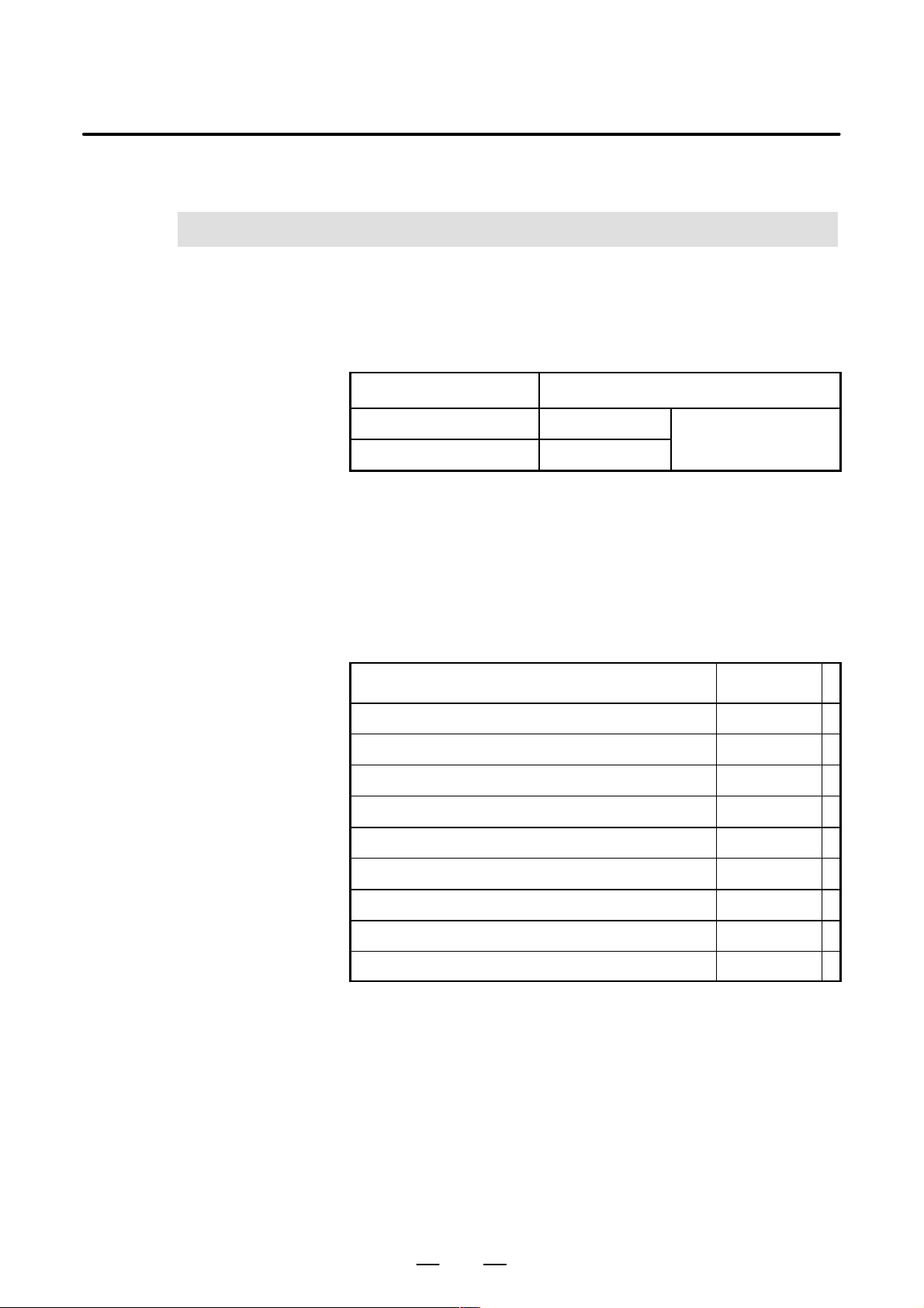
This manual describes the following models and may use the following
abbreviations.
Model name Abbreviation
FANUC Series 0i–TA 0i–TA
Series 0i
FANUC Series 0i–MA 0i–MA
For ease of understanding, the models may be categorized as follows:
T series: 0i–TA
M series: 0i–MA
1. GENERAL
Related manuals
The following table lists the manuals related to the FANUC Series 0i.
This manual is indicated by an asterisk(*).
Table 1 Manuals Related to the Series 0i
Manual name
Descriptions B–63502EN *
Connection Manual (Hardware) B–63503EN
Connection Manual (Function) B–63503EN–1
Operator’s Manual (for Lathe) B–63504EN
Operator’s Manual (for Machining Center) B–63514EN
Maintenance Manual B–63505EN
Parameter Manual B–63510EN
Macro Compiler/Macro Executor, Programming Manual B–61803E–1
FAPT Macro Compiler (for PCs), Programming Manual B–66102E
Specification
number
3
Page 28

1. GENERAL
Manuals related to the
α series servo motor
GENERAL
Manual related to the α series servo motor
B–63502EN/01
Manual name
FANUC AC Servo Motor α series Descriptions B–65142E
FANUC AC Servo Motor α series Parameter Manual B–65150E
FANUC AC Spindle Motor α series Descriptions B–65152E
FANUC AC Spindle Motor α series Parameter Manual B–65160E
FANUC Servo Amplifier α series Descriptions B–65162E
FANUC Servo Motor α series Maintenance Manual B–65165E
Specification
number
4
Page 29

B–63502EN/01
2
GENERAL
LIST OF SPECIFICATIONS
2. LIST OF SPECIFICATIONS
f : Standard F : Standard option
: Option
l
: : Function included in another option
NOTE
Some combinations of these options are
restricted.
Item Specifications
Control axis
Controlled path 1 path f f
Controlled axes per path
Simultaneously controlled axes Max. 4 axes f f
axes
Axis control by PMC
Machine controlled
Cs contouring control 1 axis f f
Axis name
Simple synchronous control 1 pair f f
Least input increment 0.001mm, 0.001deg, 0.0001inch f f
Increment system 1/10
Flexible feed gear Optional DMR f f
Fine Acc & Dec control f f
HRV control f f
Inch/metric conversion f f
Interlock
Machine lock All axes/each axis f f
Emergency stop f f
Overtravel f f
Stored stroke check 1 f f
Stroke limit external setting f —
Stored stroke check 2 f —
Stored stroke check 2, 3 — f
Mirror image Each axis f f
2 axes — f
4 axes (Including Cs axis) f l
Max. simultaneous 4 axes (Not available
on Cs axis)
Basic three axes are X, Y and Z, additional
axes are optional from U, V , W, A, B and C.
In case of G code system A, basic 2 axes
are X and Z, additional axes are optional
from Y, A, B and C.
In case of G code system B/C, basic 2
axes are X and Z, additional axes are
optional from Y, U, V, W, A, B and C.
0.0001mm, 0.0001deg,
0.00001inch
All axes/each axis/each direction/block
start/cutting block start
Series 0i
MA TA
f f
f —
— f
— f
f f
f f
5
Page 30

2. LIST OF SPECIFICATIONS
GENERAL
B–63502EN/01
Item
Follow–up f f
Servo off/mechanical handle feed f f
Chamfering on/off — f
Backlash compensation f f
Backlash compensation for each rapid traverse
and cutting
Stored pitch error compensation f f
Position switch f f
Unexpected disturbance torque detection
function
SpecificationsItem
Specifications
Series 0i
f f
f f
Operation
Automatic operation (memory) f f
DNC operation f f
MDI operation f f
Schedule function f f
Program number search f f
Sequence number search f f
Sequence number comparison and stop f f
Program restart f f
Manual intervention and return f f
Retraction for rigid tapping f —
Buffer register f f
Dry run f f
Single block f f
JOG feed f f
Manual reference position return f f
Reference position setting without DOG f f
Reference position setting with mechanical
stopper
Reference position shift f —
1 unit/each path f f
Manual handle feed
Manual handle feed rate
Manual handle interruption f f
Incremental feed x1, x10, x100, x1000 f f
Jog and handle simultaneous mode f f
2 units — f
2 units/3 units f —
x1, x10, xm, xn
m: 0–127, n: 0–1000
f f
f f
TAMA
Interpolation functions
Positioning
Single direction positioning G60 f —
Exact stop mode G61 f —
Exact stop G09 f —
Linear interpolation G01 f f
Circular interpolation G02/G03 (Multi–quadrant) f f
Dwell G04 f f
Polar coordinate interpolation — f
Cylindrical interpolation f f
G00 (Linear interpolation type positioning
is possible)
f f
6
Page 31

B–63502EN/01
GENERAL
2. LIST OF SPECIFICATIONS
Item
Helical interpolation
Threading, synchronous cutting f f
Multiple threading — f
Threading retract — f
Continuous threading — f
V ariable lead threading — f
Polygon turning — f
Skip G31 f f
High–speed skip f f
Torque limit skip — f
Reference position return G28 f f
Reference position return check G27 f f
2nd reference position return G30 f f
3rd/4th reference position return f f
Normal direction control f —
Index table indexing f —
Circular interpolation plus max. 2 axes
linear interpolation
SpecificationsItem
Specifications
Series 0i
f —
Feed function
Rapid traverse rate
Rapid traverse override Fo, 25, 50, 100% f f
Feed per minute f f
Feed per revolution f f
Tangential speed constant control f f
Cutting feedrate clamp f f
Automatic acceleration/ deceleration
Rapid traverse bell–shaped
acceleration/deceleration
Linear acceleration/ deceleration after cutting
feed interpolation
Feedrate override 0–254% f f
One–digit F code feed f —
Jog override 0–655.34% f f
Override cancel f f
Manual per revolution feed — f
External deceleration f f
Advanced preview control Look ahead of multi–blocks f —
Max. 240m/min (1mm) f f
Max. 100m/min (0.1mm) f f
Rapid traverse: linear
Cutting feed: exponential
f f
f f
f f
TAMA
Program input
Tape code EIA RS244/ISO840 f f
Label skip f f
Parity check Horizontal and vertical parity f f
Control in/out f f
Optional block skip 9 f f
Max. programmable dimension "8–digit f f
Program number O4–digit f f
Sequence number N5–digit f f
Absolute/incremental programming Combined use in the same block f f
7
Page 32

2. LIST OF SPECIFICATIONS
GENERAL
B–63502EN/01
Item
Decimal point programming/ pocket calculator
type decimal point programming
Input unit 10 time multiply f f
Diameter/radius programming (X axis) — f
Plane selection G17, G18, G19 f f
Rotary axis designation f f
Rotary axis roll–over f f
Polar coordinate command f —
Coordinate system setting f f
Automatic coordinate system setting f f
Coordinate system shift — f
Direct input of coordinate system shift — f
Workpiece coordinate system G52–G59 f f
Workpiece coordinate system preset f f
Addition of workpiece coordinate system pair 48 pairs f —
Direct input of workpiece origin offset value
measured
Manual absolute on and off f f
Direct drawing dimension programming — f
G code system
Optional chamfering/corner R f —
Programmable data input G10 f f
Sub program call 4 folds nested f f
Custom macro B f f
Addition of custom macro common variables #100–#199, #500–#999 f f
Pattern data input f f
Interruption type custom macro f f
Canned cycles — f
Multiple repetitive cycle — f
Multiple repetitive cycle II Pocket profile — f
Canned cycles for drilling f f
Small–hole peck drilling cycle f —
Circular interpolation by R programming f f
Automatic corner override f —
Automatic corner deceleration f —
Feedrate clamp based on arc radius f —
Scaling f —
Coordinate system rotation f —
Programmable mirror image f —
Tape format for F ANUC Series 10/11 f f
Conversational programming with graphic
function
Macro executor 512KB l l
A — f
B/C — f
Graphic display circuit is required l l
SpecificationsItem
Specifications
Series 0i
TAMA
f f
f f
Auxiliary/Spindle speed function
Auxiliary function M8–digit f f
2nd auxiliary function B8–digit f f
Auxiliary function lock f f
High–speed M/S/T/B interface f f
8
Page 33

B–63502EN/01
GENERAL
2. LIST OF SPECIFICATIONS
Item
Multiple command of auxiliary function 3 f f
Spindle speed function S5–digit, binary output f f
Spindle serial output S5–digit, serial output (1st/2nd) F F
Spindle analog output S5–digit, analog output F F
Constant surface speed control f f
Spindle override 0–254% f f
Actual spindle speed output — f
Spindle speed fluctuation detection — f
1st spindle orientation f f
1st spindle output switching function f f
2nd spindle orientation f f
2nd spindle output switching function f f
Spindle synchronous control f f
Multi spindle control — f
Spindle positioning — f
Rigid tapping f f
SpecificationsItem
Specifications
Series 0i
Tool function/Tool compensation
Tool function
Tool offset pairs
Tool offset memory C
Tool length compensation f —
Tool offset f f
Y–axis offset — f
Cutter compensation C f —
Tool nose radius compensation — f
Tool geometry/wear compensation — f
Tool life management f f
Extended tool life management f —
Tool offset value counter input — f
Tool length measurement f —
Automatic tool length measurement f —
Automatic tool offset — f
Direct input of tool offset value measured — f
Direct input of tool offset value measured B — f
T7 + 1/T6 + 2 digits — f
T8 digits f —
"6 digits 400 f —
"6 digits 32 pairs — f
Distinction between geometry and wear, or
between cutter and tool length
compensation.
f —
TAMA
Editing operation
Part program storage length
Number of registerable programs 200 f f
Part program editing f f
Program protect f f
Background editing f f
Extended part program editing f f
Playback f f
Note) *1 : A slight difference occurs depending on the number of registered programs and their sizes.
160m (equivalent to 64KB)*1 f f
640m (equivalent to 256KB)*1 l l
9
Page 34

2. LIST OF SPECIFICATIONS
GENERAL
B–63502EN/01
Item
SpecificationsItem
Specifications
Series 0i
Setting and display
Status display f f
Clock function f f
Current position display f f
Program display f f
Parameter setting and display f f
Self–diagnosis function f f
Alarm display f f
Alarm history display f f
Operator message history display f f
Operation history display f f
Help function f f
Run hour and parts count display f f
Actual cutting feedrate display f f
Display of spindle speed and T code at all
screens
Directory display of floppy cassette f f
Graphic function Graphic display circuit is required l l
Servo setting screen f f
Spindle setting screen Only for serial interface f f
Servo waveform display Graphic display circuit is required l l
Display of hardware and software configuration f f
Software operator’s panel l l
Software operator’s panel general purpose
switch
English f f
Japanese (Chinese character) f f
German f f
Multi–language display
Data protection key 4 types f f
Erase CRT screen display f f
French f f
Italian f f
Chinese f f
Spanish f f
Korean f f
f f
l l
TAMA
Data input/output
Reader/puncher interface
External I/O device control f f
External tool offset f f
External message f f
External machine zero point shift f f
External data input Including above 3 items f f
External key input f f
External program input f f
External workpiece number search 9999 f f
External program number search 1–9999 f f
Memory card interface for maintenance f f
Power Mate CNC manager f f
Reader/puncher (Ch.1) interface f f
Reader/puncher (Ch.2) interface f f
10
Page 35

B–63502EN/01
GENERAL
2. LIST OF SPECIFICATIONS
Item
SpecificationsItem
Specifications
Series 0i
Interface function
PC connection through HSSB l l
Basic operation package 1 l l
DNC Operation Management package l l
Others
NC ready , servo ready, automatic
operation, automatic operation start lamp,
Status output signal
Setting/display unit
Setting/display unit
Control unit dimensions
PMC–SA1
PMC
PMC–SA3
SYSTEM
Operator’s panel l l
Operator’s panel I/O module DI/DO : 48/32 points l l
Machine interface (I/O card) DI/DO : 96/64 points f f
Manual pulse generator l l
Connectable servo motor
Connectable servo amp. FANUC AC servo amp. a series, b series f f
Position detector interface (for full–closed
control)
Connectable spindle motor
Connectable spindle amp.
Input power supply DC24V"10% f f
Ambient temperature of unit
Ambient relative humidity
Vibration
feed hold, reset, NC alarm, distribution
end, rewinding, inch input, cutting,
in–position, thread cutting, tapping, etc.
9” monochrome CRT with small keyboard
MDI
8.4” color LCD with small keyboard MDI F F
2 slots
112(W) 380(H) 172(D)mm
Basic instruction: 5m sec/step
Max. step number ladder: 5000
Basic instruction: 0.15m sec/step
Max. step number ladder: 16000
FANUC AC servo motor a series, a C
series, b series
Pulse coder/optical scale (2–phase pulse
interface)
FANUC AC spindle motor a series, a C
series
FANUC servo amp. a series l l
Analog interface l l
At operating: 0°C–55°C
At non–operating: –20°C–60°C
Normally: 75%RH or less
Short term (within one month):
95%RH or less
(No dew, nor frost allowed)
At operating: 0.5G or less
At non–operating: 1G or less
f f
F F
f f
F F
F F
f f
f f
l l
f f
f f
f f
TAMA
11
Page 36

Page 37

II. NC FUNCTION
Page 38

Page 39

B–63502EN/01
PREFACE
NC FUNCTION
PREFACE
This part describes the functions that can be performed on all models. For
the functions available with each model, see the list of specifications in
Part I.
15
Page 40

1. CONTROLLED AXES
CONTROLLED AXES
1
NC FUNCTION
B–63502EN/01
16
Page 41

B–63502EN/01
NC FUNCTION
1. CONTROLLED AXES
1.1
NUMBER OF THE ALL
CONTROLLED AXES
The number of all controlled axes is the sum of the number of Cs axis.
0i–MA : 4 axes (4 machine axes)
0i–TA : 4 axes (4 machine axes)
17
Page 42

1. CONTROLLED AXES
1.2
MACHINE
CONTROLLED AXES
NC FUNCTION
B–63502EN/01
1.2.1
Number of Controlled
Paths
1.2.2
Number of Basic
Controlled Axes
1.2.3
Number of Basic
Simultaneously
Controlled Axes
1.2.4
Number of Controlled
Axes Expanded (All)
1.2.5
Number of
Simultaneously
Controlled Axes
Expanded (All)
Number of controlled paths is one.
0i–MA : 3 axes
0i–TA : 2 axes
All axes can be controlled simultaneously.
0i–MA/0i–TA : Max. 4 axes (including Cs axis)
All axes can be controlled simultaneously.
1.2.6
Axis Control by PMA
1.2.7
Cs Contour Control
0i–MA/0i–TA : Max. simultaneous 4 axes (Cs axis is disable.)
0i–MA/0i–TA : 1 axis
18
Page 43

B–63502EN/01
1.3
AXIS NAMES
NC FUNCTION
T series :
The two basic axes are always set to X and Z. Additional axes can be
selected from A, B, C, U, V, W, and Y freely.
NOTE
If U, V, or W is used as an axis name, the G code system
must be either B or C.
M series :
The three basic axes are set to X, Y, and Z. Additional axes can be
selected from A, B, C, U, V, and W freely.
1. CONTROLLED AXES
19
Page 44

1. CONTROLLED AXES
Millimeter
Millimeter
Millimeter
NC FUNCTION
B–63502EN/01
1.4
INCREMENT SYSTEM
Millimeter
machine
There are two increment systems as shown in the tables below . One of the
increment systems can be selected using a parameter.
Table 1.4(a) IS–B
Least
Least input increment
0.001 mm (diameter programming) 0.0005 mm
Metric input 0.001 mm (radius programming) 0.001 mm
0.001 deg 0.001 deg
0.0001 inch (diameter programming) 0.0005 mm
Inch input 0.0001 inch (radius programming) 0.001 mm
0.001 deg 0.001 deg
0.001 mm (diameter programming) 0.00005 inch
Metric input 0.001 mm (radius programming) 0.0001 inch
0.001 deg 0.001 deg
0.0001 inch (diameter programming) 0.00005 inch
Inch input 0.0001 inch (radius programming) 0.0001 inch
command
increment
Abbreviation
IS–B
Millimeter
machine
Millimeter
machine
0.001 deg 0.001 deg
Table 1.4(b) IS–C
Least
Least input increment
0.0001 mm (diameter programming) 0.00005 mm
Metric input 0.0001 mm (radius programming) 0.0001 mm
0.0001 deg 0.0001 deg
0.00001 inch (diameter programming) 0.00005 mm
Inch input 0.00001 inch (radius programming) 0.0001 mm
0.0001 deg 0.0001 deg
0.0001 mm (diameter programming) 0.000005 inch
Metric input 0.0001 mm (radius programming) 0.00001 inch
0.0001 deg 0.0001 deg
0.00001 inch (diameter programming) 0.000005 inch
Inch input 0.00001 inch (radius programming) 0.00001 inch
0.0001 deg 0.0001 deg
command
increment
Abbreviation
IS–C
The least command increment is in millimeters or inches, depending on
the machine tool. One of them must be selected using a parameter
beforehand.
The least input increment can be switched between metric input and inch
input by using a G code (G20 or G21) or a setting parameter.
20
Page 45

B–63502EN/01
NC FUNCTION
1. CONTROLLED AXES
1.4.1
Input Unit (10 Times)
1.5
MAXIMUM STROKE
The following least input increments can be set using a parameter:
Increment system Least input increment
IS–B 0.01 mm, 0.01 deg, or 0.0001 inch
IS–C 0.001 mm, 0.001 deg, or 0.00001 deg
NOTE
The minimum input increment for inch input is not affected.
The following table lists the maximum strokes of machine tools that are
allowed by the control unit:
Maximum stroke = Least command increment 99999999
Increment system Maximum stroke
Millimeter machine
IS–B
Inch machine
±99999.999 mm
±99999.999 deg
±9999.9999 inch
±99999.999 deg
Millimeter machine
IS–C
Inch machine
±9999.9999 mm
±9999.9999 deg
±999.99999 inch
±9999.9999 deg
NOTE
1 The values (in mm or inches) in the table are diameter
values if diameter programming is specified, or radius
values if radius programming is specified.
2 A command that exceeds the maximum stroke is not
allowed.
21
Page 46

2. PREPARATORY FUNCTIONS
PREPARA T OR Y FUNCTIONS
2
NC FUNCTION
B–63502EN/01
22
Page 47

B–63502EN/01
00
NC FUNCTION
2. PREPARATORY FUNCTIONS
2.1
T SERIES
G00 G00 G00 Positioning (Rapid traverse)
G01 G01 G01 Linear interpolation (Cutting feed)
G02 G02 G02
G03 G03 G03 Circular interpolation CCW or Helical interpolation CCW
G04 G04 G04 Dwell
G07.1
(G107)
G10 G10 G10
G11 G11 G11 Programmable data input mode cancel
G12.1
(G112)
G13.1
(G113)
G code
A B C
G07.1
(G107)
G12.1
(G112)
G13.1
(G113)
G07.1
(G107)
G12.1
(G112)
G13.1
(G113)
The following G codes are provided. The G codes are classified into
three: A, B, and C. One of the G code types can be selected using a
parameter. In this manual, G code system B is assumed.
G code list for T series (1/3)
Group Function
01
Circular interpolation CW or Helical interpolation CW
Cylindrical interpolation
00
Programmable data input
Polar coordinate interpolation mode
21
Polar coordinate interpolation cancel mode
G17 G17 G17 XpYp plane selection
G18 G18 G18 16 ZpXp plane selection
G19 G19 G19 YpZp plane selection
G20 G20 G70 Input in inch
G21 G21 G71
G22 G22 G22 Stored stroke check function on
G23 G23 G23
G25 G25 G25 Spindle speed fluctuation detection off
G26 G26 G26
G27 G27 G27 Reference position return check
G28 G28 G28 Return to reference position
G30 G30 G30
G31 G31 G31 Skip function
G32 G33 G33 Thread cutting
G34 G34 G34
G36 G36 G36 Automatic tool compensation X
G37 G37 G37
06
Input in mm
09
Stored stroke check function off
08
Spindle speed fluctuation detection on
00
2nd, 3rd and 4th reference position return
01
Variable–lead thread cutting
00
Automatic tool compensation Z
G40 G40 G40 Tool nose radius compensation cancel
G41 G41 G41 07 Tool nose radius compensation left
G42 G42 G42 Tool nose radius compensation right
23
Page 48

2. PREPARATORY FUNCTIONS
G code
A B C
G50 G92 G92 Coordinate system setting or max. spindle speed setting
G50.3 G92.1 G92.1
NC FUNCTION
G code list for T series (2/3)
Group Function
00
Workpiece coordinate system preset
B–63502EN/01
G50.2
(G250)
G51.2
(G251)
G52 G52 G52 Local coordinate system setting
G53 G53 G53
G54 G54 G54 Workpiece coordinate system 1 selection
G55 G55 G55
G56 G56 G56 Workpiece coordinate system 3 selection
G57 G57 G57
G58 G58 G58 Workpiece coordinate system 5 selection
G59 G59 G59 Workpiece coordinate system 6 selection
G65 G65 G65 00 Macro calling
G66 G66 G66 Macro modal call
G67 G67 G67
G70 G70 G72 Finishing cycle
G71 G71 G73 Stock removal in turning
G72 G72 G74 Stock removal in facing
G50.2
(G250)
G51.2
(G251)
G50.2
(G250)
G51.2
(G251)
Polygonal turning cancel
20
Polygonal turning
00
Machine coordinate system setting
Workpiece coordinate system 2 selection
14
Workpiece coordinate system 4 selection
12
Macro modal call cancel
G73 G73 G75 00 Pattern repeating
G74 G74 G76 End face peck drilling
G75 G75 G77 Outer diameter/internal diameter drilling
G76 G76 G78 Multiple threading cycle
G80 G80 G80 Canned cycle for drilling cancel
G83 G83 G83 Cycle for face drilling
G84 G84 G84 Cycle for face tapping
G86 G86 G86 10 Cycle for face boring
G87 G87 G87 Cycle for side drilling
G88 G88 G88 Cycle for side tapping
G89 G89 G89 Cycle for side boring
G90 G77 G20 Outer diameter/internal diameter cutting cycle
G92 G78 G21 01 Thread cutting cycle
G94 G79 G24 Endface turning cycle
G96 G96 G96 Constant surface speed control
G97 G97 G97
02
Constant surface speed control cancel
24
Page 49

B–63502EN/01
NC FUNCTION
G code list for T series (3/3)
G code
A B C
G98 G94 G94 Per minute feed
G99 G95 G95
Group Function
05
Per revolution feed
2. PREPARATORY FUNCTIONS
* G90 G90 Absolute programming
* G91 G91
* G98 G98 Return to initial level
* G99 G99
03
Incremental programming
11
Return to R point level
25
Page 50

2. PREPARATORY FUNCTIONS
17
04
NC FUNCTION
B–63502EN/01
2.2
M SERIES
The following G codes are provided :
G code list for M series (1/3)
G code Group Function
G00
G01
G02
G03 Circular interpolation/Helical interpolation CCW
G04 Dwell, Exact stop
G05.1 Look–ahead control (Multiple blocks are read in advance.)
G07 Hypothetical axis interpolation
G07.1 (G107) Cylindrical interpolation
G08
G09 Exact stop
G10 Programmable data input
G11 Programmable data input mode cancel
01
01
00
Positioning
Linear interpolation
Circular interpolation/Helical interpolation CW
Look–ahead control
G15
17
G16
G17
G18 02
G19 YpZp plane selection Zp: Z axis or its parallel axis
G20 Input in inch
06
G21
G22
04
G23
G27 Reference position return check
G28 Return to reference position
G29 00 Return from reference position
G30 2nd, 3rd and 4th reference position return
G31 Skip function
G33 01 Thread cutting
G37 Automatic tool length measurment
00
G39
Polar coordinates command cancel
Polar coordinates command
XpY p plane selection Xp: X axis or its parallel axis
ZpXp plane selection Yp: Y axis or its parallel axis
Input in mm
Stored stroke check function on
Stored stroke check function off
Corner offset circular interpolation
G40
G41
G42 Cutter compensation right
07
Cutter compensation cancel
Cutter compensation left
26
Page 51

B–63502EN/01
11
22
NC FUNCTION
G code list for M series (2/3)
G code Group Function
G40.1 (G150) Normal direction control cancel mode
G41.1 (G151) 19 Normal direction control left side on
G42.1 (G152) Normal direction control right side on
2. PREPARATORY FUNCTIONS
G43 Tool length compensation + direction
G44
G45 Tool offset increase
G46 Tool offset decrease
G47
G48 Tool offset double decrease
G49
G50
G51
G50.1
G51.1
G52 Local coordinate system setting
G53
G54
G54.1 Additional workpiece coordinate system selection
G55 Workpiece coordinate system 2 selection
G56
08
00
08 Tool length compensation cancel
11
22
00
14
Tool length compensation – direction
Tool offset double increase
Scaling cancel
Scaling
Programmable mirror image cancel
Programmable mirror image
Machine coordinate system selection
Workpiece coordinate system 1 selection
Workpiece coordinate system 3 selection
G57 Workpiece coordinate system 4 selection
G58 Workpiece coordinate system 5 selection
G59 Workpiece coordinate system 6 selection
G60 00/01 Single direction positioning
G61 Exact stop mode
G62 Automatic corner override
G63
G64
G65 00 Macro call
G66 Macro modal call
G67
G68 Coordinate rotation
G69
G73 Peck drilling cycle
G74
15
12
16
09
Tapping mode
Cutting mode
Macro modal call cancel
Coordinate rotation cancel
Counter tapping cycle
27
Page 52

2. PREPARATORY FUNCTIONS
09
05
10
G code Group Function
G76 09 Fine boring cycle
NC FUNCTION
G code list for M series (3/3)
B–63502EN/01
G80
G81 Drilling cycle, spot boring cycle or external operation function
G82 Drilling cycle or counter boring cycle
G83 Peck drilling cycle
G84
G85
G86 Boring cycle
G87 Back boring cycle
G88 Boring cycle
G89 Boring cycle
G90
G91
G92 Setting for work coordinate system or clamp at maximum spindle speed
G92.1
G94
G95
09
03
00
05
Canned cycle cancel/external operation function cancel
Tapping cycle
Boring cycle
Absolute command
Increment command
Workpiece coordinate system preset
Feed per minute
Feed per rotation
G96 Constant surface speed control
G97
G98
G99
13
Constant surface speed control cancel
Return to initial point in canned cycle
10
Return to R point in canned cycle
28
Page 53

B–63502EN/01
3
NC FUNCTION
INTERPOLATION FUNCTIONS
3. INTERPOLATION FUNCTIONS
29
Page 54

3. INTERPOLATION FUNCTIONS
NC FUNCTION
B–63502EN/01
3.1
POSITIONING (G00)
Either of the following tool paths can be selected accroding to bit 1 of
parameter No. 1401.
D Non linear interpolation positioning
The tool is positioned with the rapid traverse rate for each axis
separately. The tool path is normally straight.
D Linear interpolation posioning
The tool path is the same as in linear interpolation (G01). The tool is
positioned within the shortest possible time at a speed that is not more
than the rapid traverse rate for each axis.
Linear interpolation
positioning
End position
Start position
Non linear interpolation
positioning
It is decelerated, to a stop at the end point, and imposition check is
performed (checks whether the machine has come to the specified
position). The in-position check can be suppressed using a parameter.
Width of imposition can be set as a parameter.
Format
G00 _ ;
IP
_ ; Indicates a combination of axes such as X_Y_Z_.
IP
30
Page 55

B–63502EN/01
NC FUNCTION
3. INTERPOLATION FUNCTIONS
3.2
M series
SINGLE DIRECTION
POSITIONING (G60)
(M series)
Format
It is always controlled to perform positioning to the end point from a
single direction, for better precision in positioning. If direction from start
point to end point is different from the predecided direction, it once
positions to a point past the end point, and the positioning is reperformed
for that point to the end point.
Even if the direction from start point to end point is the same as predecided
direction, the tool stops once before the end point.
Exceeded
amount
End point
G60 _ ;IP
Temporary stop
31
Page 56

3. INTERPOLATION FUNCTIONS
NC FUNCTION
B–63502EN/01
3.3
LINEAR
INTERPOLATION
(G01)
Format
Linear interpolation is done with tangential direction feed rate specified
by the F code.
X axis
End point
(200, 150)
(Program example)
G01 G90 X200. Z150. F200 ;
Start point
Z axis
G01 _ F_ ;IP
F : Feedrate
32
Page 57

B–63502EN/01
NC FUNCTION
3. INTERPOLATION FUNCTIONS
3.4
CIRCULAR
INTERPOLATION
(G02, G03)
Circular interpolation of optional angle from 0° to 360° can be specified.
G02: Clockwise (CW) circular interpolation
G03: Counterclockwise (CCW) circular interpolation
Yp
G03
G02
G17
Xp
Xp
G02
G18
G03
Zp
Zp
G03
G02
Yp
G19
Feed rate of the tangential direction takes the speed specified by the F
code. Planes to perform circular interpolation is specified by G17, G18,
G19. Circular interpolation can be performed not only on the X, Y, and
Z axis but also on the parallel axes of the X, Y, and Z axes.
G17: Xp-Yp plane
G18: Zp-Xp plane
G19: Yp-Zp plane
where
Xp: X axis or its parallel axis
Yp: Y axis or its parallel axis
Zp: Z axis or its parallel axis
Parameter is set to decide which parallel axis of the X, Y, Z axes to be the
additional axis.
Format
Arc on the Xp-Y p plane
G17
Arc on the Zp-Xp plane
G18
Arc on the Yp-Zp plane
G19
I_. J_, K_:Distance of the X, Y, Z axes from the start point to the center of
the circle
R:Arc radius (For an arc having a central angle of 180° or greater, specify
an R value with a minus sign. A complete circumference cannot be specified.)
Y
X
Center
G02
G03
G02
G03
G02
G03
End point
(x, y)
i
Xp_ Yp_
Zp_ Xp_
Yp_ Zp_
X
Start
point
j
Z
Center
R_
I_ J_
R_
K_ I_
R_
J_ K_
End point
(z, x)
k
F_ ;
F_ ;
F_ ;
Start
point
i
Z
Y
Center
End point
(y , z)
j
Start
point
k
33
Page 58

3. INTERPOLATION FUNCTIONS
NC FUNCTION
B–63502EN/01
Valid radius range for circular interpolation is expanded as follows:
Input increments
Metric input Inch input
Increment
system
IS–B 0.001 to 99999.999mm 0.0001 to 9999.9999inch
IS–C 0.0001 to 9999.9999mm 0.00001 to 999.99999inch
34
Page 59

B–63502EN/01
NC FUNCTION
3. INTERPOLATION FUNCTIONS
3.5
M series
HELICAL
INTERPOLATION
(G02, G03)
Helical interpolation performs circular interpolation of a maximum of
two axes, synchronizing with other optional two axes circular
interpolation. Thread cutting of lar ge radius threads or machining of solid
cams are possible by moving a tool in a spiral.
The commanded speed is the speed of the tangential direction of the arc.
Thus, the speed of a linear axis is expressed as follows:
Lengthoflinearaxis
F
Arclength
Z
Tool path
X
Tangential speed along an arc by circular interpolation
is the rate specified in programming.
Y
Format
Arc on the Xp-Y p plane
G17
Arc on the Zp-Xp plane
G18
Arc on the Yp-Zp plane
G19
α, β: Optional axis other than the circular interpolation axes
G02
G03
G02
G03
G02
G03
Xp_ Yp_
Zp_ Xp_
Yp_ Zp_
R_
I_ J_
R_
K_ I_
R_
J_ K_
α_ (β_) F_ ;
α_ (β_) F_ ;
α_ (β_) F_ ;
35
Page 60

3. INTERPOLATION FUNCTIONS
NC FUNCTION
B–63502EN/01
3.6
T series
POLAR COORDINATE
INTERPOLATION
(G12.1, G13.1)
Format
Explanations
D Polar coordinate
interpolation mode
(G12.1)
The function in which contour control is done in converting the command
programmed in a cartesian coordinate system to the movement of a linear
axis (movement of a tool) and the movement of a rotary axis (rotation of
a workpiece) is the polar coordinate interpolation. It is an effective
function when a straight line groove is cut on the outer diameter of a
workpiece or when a cam shaft is ground.
Whether the polar coordinate interpolation is done or not is commanded
by a G code.
These G codes shall be commanded in a single block.
G12.1; Polar coordinate interpolation mode
(Polar coordinate interpolation shall be done.)
G13.1; Polar coordinate interpolation cancel mode
(Polar coordinate interpolation is not done.)
The axes (linear axis and rotary axis) on which polar coordinate
interpolation is done are set beforehand by parameters.
Change the mode to polar coordinate interpolation mode by commanding
G12.1, and a plane (hereinafter referred to as polar coordinate
interpolation plane) is selected in which linear axis is made to the first
axis of the plane, and virtual axis being a right angle with the linear axis
is made to the second axis of the plane. Polar coordinate interpolation is
carried out on this plane.
In the polar coordinate interpolation made, the command of linear
interpolation (G01) and circular interpolation (G02, G03) is possible.
And both absolute command (G90) and incremental command (G91) are
possible.
As for feedrate, specify the tangential speed (relative speed between the
workpiece and the tool) on the polar coordinate interpolation plane
(cartesian coordinate system) with F.
D Polar coordinate
interpolation cancel
mode (G13.1)
The polar coordinate interpolation cancel mode is obtained by G13.1
command.
36
Page 61

B–63502EN/01
Examples
NC FUNCTION
(X axis is diameter programming and C axis is radius programming)
00001;
:
N100 G90 G00 X120.0 C0 Z_ ;
N200 G12.1;
N201 G42 G01 X40.0 F D01
N202 C10.0;
N203 G03 X20.0 C20.0 R10.0 ;
N204 G01 X-40.0 ;
N205 G-10.0 ;
N206 G03 X-20.0 C-20.0 I10.0 K0 ;
N207 G01 X40.0 ;
N208 C0 ;
N209 G40 X120.0 ;
N210 G13.1 ;
N300 Z_ ;
N400 X_ C_ ;
:
M30 ;
;
Positioning to the starting position
Starting polar coordinate interpolation
Contour program
(Program in cartesian coordinate
system of X-C plane)
Canceling polar coordinate
interpolation
3. INTERPOLATION FUNCTIONS
37
Page 62

3. INTERPOLATION FUNCTIONS
NC FUNCTION
B–63502EN/01
3.7
CYLINDRICAL
INTERPOLATION
(G07.1)
Format
Explanations
D Cylindrical interpolation
mode
When the form on the expanded side view of a cylinder (from on the
cylinder coordinate system) is commanded by a program command, the
NC converts the form into a linear axis movement and a rotary axis
movement then performs a contour control. This feature is called the
cylindrical interpolation.
Cylindrical interpolation is commanded with G07.1.
G07.1 (Name of rotary axis) Radius value of cylinder ;
Cylindrical interpolation mode
G07.1 (Name of rotary axis) 0 ;
Cancellation mode of cylindrical interpolation
Cylindrical interpolation is made between the rotary axis specified in the
block of G07.1 and the other optional linear axis.
Circle interpolation command is allowed as well as linear interpolation,
during cylindrical interpolation mode. Also, absolute command and
incremental command can be made. Cutter compensation can be added
to the program command. Cylindrical interpolation is made for the path
after cutter compensation.
Feed rate gives the tangential speed on the expanded plane of the cylinder
with F.
D Cancellation mode of
cylindrical interpolation
G07.1 (Name of rotary axis) 0; Cancellation mode of cylindrical
interpolation is made when commanded as above.
38
Page 63

B–63502EN/01
Examples
NC FUNCTION
3. INTERPOLATION FUNCTIONS
An example of a program
C
O0001 (CYLINDRICAL INTERPOLATION);
N1 G00 G00 Z100.0 C0;
N2 G01 G18 Z0 C0;
N3 G7.1 C57299;
Z
R
N4 G01 G42 Z120.0 D10 F250;
N5 G40.0;
N6 G02 Z90.0 C60.0 R30.0 ;
N7 G01 Z70.0;
N8 G03 Z60.0 C70.0 R10.0;
N9 G01 C150.0;
N10 G03 Z70.0 C190.0 R75.0;
N11 G01 Z110.0 C230.0;
N12 G02 Z120.0 C270.0 R75.0;
N13 G01 G360.0;
N14 G40 Z100.0;
N15 G07.1 C0;
N16
M30;
Z
mm
120
110
90
70
60
N05
N06
N11
N07
N08
0
30
60 70
N09
N10
150
N12
230190
270
N13
360
deg
C
39
Page 64

4. THREAD CUTTING
THREAD CUTTING
4
NC FUNCTION
B–63502EN/01
40
Page 65

B–63502EN/01
NC FUNCTION
4. THREAD CUTTING
4.1
EQUAL LEAD
THREAD CUTTING
(G33) (WITH G CODE
SYSTEM A: G32)
Format
By feeding the tool synchronizing with the spindle rotation, thread
cutting of the specified lead is performed. In addition to straight threads,
taper threads and scroll threads can be cut with equal leads.
L
Straight thread
L
L
T aper thread
Scroll thread
Explanations
IP
G33 _ F_ :
F_ : Lead along the long axis
(axis having the largest amount of travel)
To form a single thread, threading is generally performed several times
from rough machining to finish machining along the same path.
Threading starts when the one-revolution signal from the position coder
attached to the spindle is detected. So threading always starts at the same
point on the circumference of the workpiece, and threading is performed
along the same path on the workpiece. In this case, however, the shaft
must rotate at a constant speed during operations from rough machining
to finish machining. If the spindle speed changes, an accurate thread may
not be produced.
The following shows the specifiable lead range:
D M series
Metric input F1 to F50000 (0.01 to 500.00mm)
Inch input F1 to F99999 (0.0001 to 9.9999inch)
D T series
Metric input 0.0001 to 500.0000mm
Specifiable lead range
Specifiable lead range
Inch input 0.000001 to 9.999999inch
NOTE
Leads exceeding the maximum cutting feed speed when
converted to per minute feed speed cannot be specified.
41
Page 66

4. THREAD CUTTING
NC FUNCTION
B–63502EN/01
4.2
T series
MULTIPLE–THREAD
CUTTING (G33)
(T series)
Format
Multiple–thread screws
Constant–lead threading
G33 _ F_ Q_ ;
IP
G33 _ Q_ ;
IP
IP
_ : End point
F_ : Lead in longitudinal direction
Q_ : Threading start angle
4.3
T series
VARIABLE LEAD
THREAD CUTTING
(G34) (T series)
Format
Variable lead thread cutting can be done by commanding long axis
direction lead and lead increase/decrease per spindle rotation.
G34 _ F_ K_ :
Metric input ±0.0001 to±500.0000 mm/rev
Inch input ±0.000001 to±9.999999 inch/re
IP
F_ : Long axis direction lead at start point
K_ : Lead increase/decrease per spindle rotation
Command value range of
lead increase/decrease (K) per spindle rotation:
42
Page 67

B–63502EN/01
NC FUNCTION
4. THREAD CUTTING
4.4
T series
CONTINUOUS
THREAD CUTTING
(T series)
Continuous thread cutting in which thread cutting command block is
continuously commanded is available. As it is controlled so that the
spindle synchronism shift (occurred when shifting from one block to
another) is kept to a minimum, special threads like threads which leads
or shape change during the cycle can also be cut.
G33
G33
G33
43
Page 68

5. FEED FUNCTIONS
FEED FUNCTIONS
5
NC FUNCTION
B–63502EN/01
44
Page 69

B–63502EN/01
NC FUNCTION
5. FEED FUNCTIONS
5.1
RAPID TRAVERSE
Positioning of each axis is done in rapid motion by the positioning
command (G00).
There is no need to program rapid traverse rate, because the rates are set
in the parameter (per axis).
Least command increment Rapid traverse rate range
0.001mm, deg 30 to 240000mm/min, deg/min
0.0001mm, deg 30 to 100000mm/min, deg/min
0.0001inch 3.0 to 9600.0inch/min
0.00001inch 3.0 to 4000.0inch/min
NOTE
The above feed rates are limits according to the NC’s
interpolation capacity when the high-resolution detection
interface is equipped. When the whole system is
considered, there are also limits according to the servo
system. For details, refer to Appendix A.
45
Page 70

5. FEED FUNCTIONS
NC FUNCTION
B–63502EN/01
5.2
CUTTING FEED RATE
5.2.1
Tangential Speed
Constant Control
5.2.2
Cutting Feed Rate
Clamp
5.2.3
Per Minute Feed (G94)
Feed rates of linear interpolation (G01), and circular interpolation (G02,
G03) are commanded with numbers after the F code.
In cutting feed, it is controlled so that speed of the tangential direction is
always the same commanded speed.
Cutting feed rate upper limit can be set as parameters. If the actual cutting
feed rate (feed rate with override) is commanded exceeding the upper
limit, it is clamped to a speed not exceeding the upper limit.
With the per minute feed mode G94, tool feed rate per minute is directly
commanded by numerical value after F.
Least command increment Cutting feed rate range
0.001mm, deg 1 to 240000mm/min, deg/min
0.0001mm, deg 1 to 100000mm/min, deg/min
0.0001inch 0.01 to 9600.0inch/min
0.00001inch 0.01 to 4000.0inch/min
NOTE
The above feed rates are limits according to the NC’s
interpolation capacity. When the whole system is
considered, there are also limits according to the servo
system. For details, see Appendix A.
46
Page 71

B–63502EN/01
NC FUNCTION
5. FEED FUNCTIONS
5.2.4
Per Revolution Feed
(G95)
D M series
D T series
With the per revolution feed mode G95, tool feed rate per revolution of
the spindle is directly commanded by numeral after F. A position coder
must be mounted on the spindle.
For the T series, however, the feed–per–revolution command can be
enabled by setting the corresponding parameter accordingly, even when
the position coder is not installed.
Least command increment Cutting feed rate range
0.001mm, deg 0.01 to 500.00mm/rev , deg/rev
0.0001mm, deg 0.01 to 500.00mm/rev , deg/rev
0.0001inch 0.0001 to 9.9999inch/rev
0.00001inch 0.0001 to 9.9999inch/rev
Least command increment Cutting feed rate range
0.001mm, deg 0.0001 to 500.0000mm/rev , deg/rev
0.0001mm, deg 0.0001 to 500.0000mm/rev , deg/rev
0.0001inch 0.000001 to 9.999999inch/rev
0.00001inch 0.000001 to 9.999999inch/rev
NOTE
The above feed rates are limits according to the NC’s
interpolation capacity. When the whole system is
considered there are also limits according to the servo
system. For details, See Appendix A.
5.2.5
M series
F1–digit Feed (M
series)
When a 1-digit number from 1 to 9 is commanded after the F, the preset
speed corresponding the 1-digit number commanded is set as feed rate.
When F0 is commanded, rapid traverse is set.
Set the F1-digit feed rate change input signal on from the machine side,
and rotate the manual pulse generator . Feed rate of the currently selected
speed can be changed.
Feed rate set or changed will be memorized even after power is turned
off.
47
Page 72

5. FEED FUNCTIONS
5.3
OVERRIDE
NC FUNCTION
B–63502EN/01
5.3.1
Feed Rate Override
5.3.2
Rapid T raverse
Override
5.3.3
Override Cancel
5.3.4
Jog Override
The per minute feed (G94) and per rotation feed (G95) can be overrided
by:
0 to 254% (per every 1%).
Feed rate override cannot be performed to F1-digit feed.
Feed rate also cannot be performed to functions as thread cutting and
tapping in which override is inhibited.
Rapid traverse rate can be overridden by:
F0, 25%, 50%, 100%.
F0: A constant speed per axis can be set by parameter
An override of 0% to 100% can be applied in 1% steps using a signal.
Feed rate override and the second feed rate override can be clamped to
100% by a signal from the machine side.
The manual continuous feedrate and incremental feed rate can be
overridden by:
0% to 655.34% (in steps of 0.01%)
48
Page 73

B–63502EN/01
NC FUNCTION
5. FEED FUNCTIONS
5.4
AUTOMATIC
ACCELERATION/
DECELERATION
Acceleration and deceleration is performed when starting and ending
movement, resulting in smooth start and stop.
Automatic acceleration/deceleration is also performed when feed rate
changes, so change in speed is also smoothly done.
Rapid traverse : Linear acceleration/deceleration
(time constant is parameter set per axis)
Cutting feed : Exponential acceleration/deceleration
(time constant is parameter set per axis)
Jogging : Exponential acceleration/deceleration
(time constant is parameter set per axis)
Rapid traverse
F
R
0
T
R
Jog feed
F
C
: Rapid traverse
F
R
: Acceleration/
T
R
deceleration time
constant
T
Time
R
F
:Feed rate
C
: Acceleration/
T
C
deceleration time
constant
0
T
C
Feed, Dry run
F
J
0
T
J
T
C
FJ : Jog feed rate
TJ : Jog feed time
FL : Low feed rate after
F
L
T
J
Time
constant
deceleration
Time
49
Page 74

5. FEED FUNCTIONS
NC FUNCTION
B–63502EN/01
5.5
RAPID TRAVERSE
BELL–SHAPED
ACCELERATION/
DECELERATION
The function for rapid traverse bell–shaped acceleration/deceleration
increases or decreases the rapid traverse feedrate smoothly.
This reduces the shock to the machine system due to changing
acceleration when the feedrate is changed.
As compared with linear acceleration/deceleration, bell–shaped
acceleration/deceleration allows smaller time constants to be set,
reducing the time required for acceleration/deceleration.
Linear acceleration/deceleration
for rapid traverse
Feedrate
0
Time
Acceleration
0
Time
Bell–shaped acceleration/
deceleration for rapid traverse
Feedrate
0
Time
Acceleration
0
Time
50
Page 75

B–63502EN/01
5.6
LINEAR
ACCELERATION/
DECELERATION
AFTER CUTTING
FEED
INTERPOLATION
NC FUNCTION
Speed
5. FEED FUNCTIONS
T
C
T
C
Time
In the linear acceleration/deceleration, the delay for the command caused
by the acceleration/ deceleration becomes 1/2 compared with that in
exponential acceleration/deceleration, substantially reducing the time
required for acceleration and deceleration.
Also, the radius direction error in the circular interpolation caused by the
acceleration/deceleration is substantially reduced.
Z
∆r
∆r: Maximum value of radius
Command
path
Actual
path
r
Z
error (mm)
v : Feedrate (mm/sec)
r : Circular radius (mm)
: Acceleration/
T
1
deceleration time
constant (sec)
T2: Time constant of servo
motor (sec)
The maximum value of error in this radius direction is obtained
approximately by the following equation.
Dr + (
Dr + (
1
2
24
2
1
T
)
1
2
2
1
T
)
1
2
2
V
T
)
2
r
2
2
V
1
T
)
2
r
2
For exponential acceleration/deceleration. . . . .
For linear acceleration/deceleration after . . . . .
cutting feed interpolation
Consequently, in case of the linear acceleration/deceleration after
interpolation, if an error caused by the servo loop time constant is
excluded, the radius directional error will be reduced to 1/12, compared
with the exponential acceleration/deceleration.
51
Page 76

5. FEED FUNCTIONS
NC FUNCTION
B–63502EN/01
5.7
M series
LINEAR
ACCELERATION/
DECELERATION
BEFORE CUTTING
FEED
INTERPOLATION
D Exponential
acceleration/deceleration
after cutting feed
interpolation
Interpolation
f
(pulse distribution)
In response to the cutting feed command , the feedrate before
interpolation, the command feedrate can be directly accelerated/
decelerated. This enables a machined shape error caused by the delay of
acceleration/deceleration to be eliminated.
Linear acceleration/deceleration before cutting feed interpolation is
enabled during advanced view control.
f
tt
Acceleration/
deceleration control
T
C
Servo
control
Motor
D Linear acceleration/
deceleration after cutting
feed interpolation
f
D Linear acceleration/
deceleration before
cutting feed interpolation
Acceleration/deceleration applied to
feedrate command
Interpolation
(pulse distribution)
f
Servo
t
T
C
Interpolation (Pulse destribution)
f
T
C
T
C
T
C
t
t
control
Servo
control
Motor
Motor
52
Page 77

B–63502EN/01
NC FUNCTION
5. FEED FUNCTIONS
5.8
T series
ERROR DETECTION
(T series)
Generally, the CNC does not zero the feedrate at the interface of two
blocks during cutting feed.
Because of this, a corner of a tool path may be rounded.
This part causes the corner of the tool
path to be rounded.
Feedrate
Time
Programmed tool path
Actual tool–center path
If the error detect signal is used, it is possible to specify that
a block not be started until the acceleration/deceleration
of the previous block has been completed.
Feedrate
NOTE
If the error detect signal is on, a cutting block is not executed
until the acceleration/deceleration of the previous cutting
block has been completed.
This function alone cannot prevent corner rounding due to
delay caused by the servo motor, however.
To prevent corner rounding due to delay caused by the
servo motor, use the in–position check function together
with this function.
After acceleration/
deceleration
Feedrate
Range od in–position check
After servo motor delay
Time
Time
53
Page 78

5. FEED FUNCTIONS
NC FUNCTION
B–63502EN/01
5.9
M series
EXACT STOP (G09)
(M series)
5.10
M series
EXACT STOP MODE
(G61) (M series)
Move command in blocks commanded with G09 decelerates at the end
point, and in–position check is performed. G09 command is not
necessary for deceleration at the end point for positioning (G00) and
in–position check is also done automatically . This function is used when
sharp edges are required for workpiece corners in cutting feed.
Exact stop off
Exact stop on (The in-position
check is performed at the end of
a block.)
When G61 is commanded, deceleration of cutting feed command at the
end point and in–position check is performed per block thereafter. This
G61 is valid till G64 (cutting mode), G62 (automatic corner override), or
G63 (tapping mode) is commanded.
5.11
M series
CUTTING MODE (G64)
(M series)
5.12
M series
T APPING MODE (G63)
(M series)
5.13
M series
AUTOMA TIC CORNER
OVERRIDE (G62)
(M series)
When G64 is commanded, deceleration at the end point of each block
thereafter is not performed and cutting goes on to the next block. This
command is valid till G61 (exact stop mode), G62 (automatic corner
override), or G63 (tapping mode) is commanded.
When G63 is commanded, feed rate override is ignored (always regarded
as 100%), and feed hold also becomes invalid. Cutting feed does not
decelerate at the end of block to transfer to the next block. And in-tapping
signal is issued during tapping operation. This G63 is valid till G61
(exact stop mode), G62 (automatic corner override), or G64 (cutting
mode) is commanded.
When G62 is commanded during cutter compensation, cutting feed rate
is automatically overridden at corner . The cutting quantity per unit time
of the corner is thus controlled not to increase. This G62 is valid till G61
(exact stop mode), G64 (cutting mode), or G63 (tapping mode) is
commanded.
54
Page 79

B–63502EN/01
NC FUNCTION
5. FEED FUNCTIONS
5.14
DWELL (G04)
Format
With the G04 command, shifting to the next block can be delayed.
When commanded with a per minute feed mode (G94), shifting to the next
block can be delayed for the commanded minutes.
When commanded with a per rotation feed mode (G95), shifting to the
next block can be delayed till the spindle rotates for the commanded
times.
Dwell may always be performed by time irrespective of G94 and G95 by
parameter selection.
Per second dwell
G94 G04
P_ or X_ : Dwell time commanded in seconds (0.001-99999.999 sec)
Per revolution dwell
G95 G04
P_ or X_ : Spindle rotation angle commanded in rev.
P_
;
X_
P_
;
X_
(0.001-99999.999 rev)
55
Page 80

6. REFERENCE POSITION
REFERENCE POSITION
6
NC FUNCTION
B–63502EN/01
56
Page 81

B–63502EN/01
NC FUNCTION
6. REFERENCE POSITION
6.1
MANUAL
REFERENCE
POSITION RETURN
6.2
SETTING
THE REFERENCE
POSITION WITHOUT
DOGS
Explanations
D Setting the reference
position
D Reference position
return
Positioning to the reference position can be done by manual operation.
With jogging mode (JOG), manual reference position return (ZRN)
signals, and signal for selecting manual reference position return axis (±J1
to ±J8) on, the tool the machine is turned on, it decelerates, and when it
is turned off again, it stops at the first grid point, and reference position
return end signal is output. This point is the reference position.
By performing manual reference position return, the machine coordinate
system and the work coordinate system is established.
There is only one method available to perform manual reference point
return:
In the grid method, a certain grid of the position detection is appointed as
the reference position. The reference position position can be shifted by
the grid shift function.
This function moves the machine to around the reference position set for
each axis in the manual continuous feed mode. Then it sets the reference
position for the machine in the manual reference position return mode
without the deceleration signal for reference position return. With this
function, the machine reference position can be set at a given position
without the deceleration signal for reference position return.
1 Place the machine in the manual continuous feed mode, and perform
positioning to a position near but not exceeding the reference position
from reference position return direction (setting by parameter).
2 Enter the manual reference position return mode, then input the feed
axis direction select signal (+) or (–) for the axis.
3 Positioning is made at the grid point located nearest from the current
point to reference position return direction. This point is recorded as
the reference position. If the absolute-position detector is provided,
the set reference position is retained after the power is turned off. In
this case, when the power is turned on again, there is no need for setting
the reference position again.
1 After the reference position is set, when the feed axis select signal (+)
or (–) is input for the axis in the reference position return mode,
reference position return operation is performed in rapid traverse
regardless of which signal (+) or (–) is input.
57
Page 82

6. REFERENCE POSITION
6.3
AUTOMATIC
REFERENCE
POSITION RETURN
(G28, G29)
NC FUNCTION
B–63502EN/01
D Return to reference
position (G28)
D Return from reference
position (G29)
(only for M series)
With the G28 command, the commanded axis is positioned to the
reference position via the commanded point. After positioning, the
reference position return end lamp lights. If G28 was commanded when
reference position return is not performed after power on, reference
position return is done in the same sequence as the manual reference
position return.
G28 _ ;
IP
: Command intermediate point
IP
With the G29 command, the commanded axis is positioned to the point
commanded by G29, via the intermediate point commanded by G28.
G29 _ ;IP
Y
B
A
Intermediate
point
Reference position
R
Suppose tool change
was performed at R.
The programmer
need not calculate a
concrete movement
value between the
intermediate point
and the reference
C
position
.
Example of use of G28 and G29
58
X
Page 83

B–63502EN/01
NC FUNCTION
6. REFERENCE POSITION
6.4
REFERENCE
POSITION RETURN
CHECK (G27)
Format
6.5
2ND, 3RD AND 4TH
REFERENCE
POSITION RETURN
(G30)
This function is used to check whether the reference position return
command was performed correctly.
When G27 is commanded, the commanded axis is positioned to the
specified position, reference position return end signal is output if
reference position return is performed to the correct position, and alarm
arises it is not positioned correctly to the reference point.
This function is available after power is turned on an reference point
return is performed.
G27 _ ;IP
With the G30 command, the commanded axis is positioned to the 2nd,
3rd, or the 4th reference position, via the commanded point. 2nd, 3rd, or
4th reference position return end signal is output when positioning ends.
Set the 2nd, 3rd, and 4th reference position position as parameters.
This function is available after power is turned on and reference position
return is performed.
G29 can be used to return from the 2nd, 3rd, and 4th reference point (same
as reference position return, G28) (M series only).
Format
G30
P2
P3
P4
P2, P3, P4: Select from 2nd, 3rd, or 4th reference positions.
_ ;
IP
If not selected, 2nd reference position return is
automatically selected.
59
Page 84

6. REFERENCE POSITION
NC FUNCTION
B–63502EN/01
6.6
M series
REFERENCE
POSITION SHIFT
6.7
BUTT–TYPE
REFERENCE
POSITION SETTING
For reference position return using the grid method, you can shift the
reference position without having to move the deceleration dog, simply
by setting the amount of shift in a parameter.
The time required to adjust the reference position is thus greatly reduced
because the deceleration dog need not be adjusted.
Direction of reference
L
Deceleration dog
Grid point
L
: Reference position shift
SFT
L
: Distance the tool moves between the deceleration dog being
DEC
turned off and the first grid point encountered subsequently
(grid point when the reference position shift is 0)
(L
DEC
DEC
is displayed on the diagnostic screen.)
L
SFT
position return
Machine
zero point
The butt–type reference position setting function automates the setting of
a reference position by butting the tool against a mechanical stopper on
an axis. This function is provided to eliminate the variations in reference
position setting that arise when the procedure is performed by different
operators, and to minimize the amount of work involved in making fine
adjustments after reference position setting.
Select the axis for which the reference position is to be set, then perform
cycle start. The following operations are performed automatically:
1. The torque (force) of the selected axis is reduced so that the butting
feedrate is constant. The tool is butted against the mechanical stopper .
Then, the tool is drawn back a parameter–set amount from the
mechanical stopper.
2. Again, the torque (force) of the selected axis is reduced, then the tool
is butted against the mechanical stopper. Then, the tool is drawn back
a parameter–set amount from the mechanical stopper.
3. The point on the axis to which the tool is drawn back is set as the
reference position.
60
Page 85

B–63502EN/01
7
NC FUNCTION
COORDINATE SYSTEMS
By teaching the CNC the position the tool is to arrive, the CNC moves
the tool to that position. The position is specified using coordinates on a
certain coordinate system.
There are three types of coordinate systems.
D Machine coordinate system
D Workpiece coordinate system
D Local coordinate system
As necessary, one of the above coordinate systems is used for specifying
coordinates for the target position of the tool.
7. COORDINATE SYSTEMS
61
Page 86

7. COORDINATE SYSTEMS
NC FUNCTION
B–63502EN/01
7.1
MACHINE
COORDINATE
SYSTEM (G53)
Format
Machine coordinate system is a coordinate system set with a zero point
proper to the machine system.
A coordinate system in which the reference point becomes the
parameter-preset coordinate value when manual reference point return is
performed, is set. With G53 command, the machine coordinate system
is selected and the axis is able to be moved in rapid traverse to the position
expressed by the machine coordinates.
G53 _ ;IP
62
Page 87

B–63502EN/01
NC FUNCTION
7. COORDINATE SYSTEMS
7.2
WORKPIECE
COORDINATE
SYSTEM
7.2.1
Setting a Workpiece
Coordinate System
(Using G92)
(with G Code System A:
G50)
A coordinate system in which the zero point is set to a fixed point on the
workpiece, to make programming simple.
A workpiece coordinate system may be set by using one of the following
methods:
(1) Using G92 (G50 for T series with G code system A)
(2) Automatic setting
(3) Using G54 to G59
When (1) is used, a workpiece coordinate system is established using the
numeric value programmed after G92.
When (2) is used, a workpiece coordinate system is automatically
established upon a manual reference position return.
When (3) is used, six workpiece coordinate systems must be set from the
MDI panel in advance. The workpiece coordinate system to be used is
selected by specifying a code selected from G54 to G59.
Format
Examples
D Example 1
(G90) G92 _ ;IP
By using the above command, a workpiece coordinate system can be set
so that the current tool position is at a specified position.
T seriesM series
Z
23.0
0
G92 X25.2 Z23.0 ;
25.2
X
X
Reference point
375.1
φ128.7
Start
point
Z
63
G92 128.7 Z375.1 ;
(diameter programming)
Page 88

7. COORDINATE SYSTEMS
NC FUNCTION
B–63502EN/01
D Example 2
Set the reference point on the tool holder or turret as shown in the figure
below, then specify G92 at the beginning of the program. By specifying
an absolute command in this condition, the reference point is moved to
a specified position. To move the tool tip to a specified position,
compensate the distance between the reference point and the tool tip by
using tool length compensation (for the M system) or tool offset (for the
T system).
Reference
point
1200.0
0
G92 600.0 Z1200.0 ;
Setting the start point at a given
reference point on the tool holder
600.0
T seriesM series
700.0
Start point
= reference
position
φ1200.0
Z
X
G92 1200.0Z700.0 ;
(diameter programming)
Setting the start point at a given reference
point on the turret
D Example 3
(Shift of a workpiece
coordinate system)
Format
T series
When a new workpiece coordinate system is created by specifying G92,
it is determined so that a given point on the tool has a given coordinate
value. So, there is no need to be concerned with old workpiece coordinate
systems. Particularly when the start point for machining is determined
based on the workpiece, the G92 command is useful. In this case, a desired
coordinate system can newly be created even if an old workpiece
coordinate system is invalid.
A workpiece coordinate system can be shifted by using the following
command:
When this command is specified, a new coordinate system is created so
that the current coordinate value (x, z) at a given point on the tool (for
example, the tool tip) becomes (x+u, z+w).
For the x and u values, diameters must be set if diameter programming
is specified, or radii must be set if radius programming is specified.
(G91) G92 X(u) Z(w) ;
With G code system A: G50U(u)W(w);
64
Page 89

B–63502EN/01
Examples
NC FUNCTION
7. COORDINATE SYSTEMS
10.2
30.56
Z
When tool A is switched to tool B, G91 G92 X20.4 Z30.56 (diameter
programming) is specified.
7.2.2
Automatic Coordinate
System Setting
When manual reference position return is performed, a workpiece
coordinate system can be set automatically so that the current tool
position at the reference position becomes a desired position is set in
advance. This functions as if G92IP__; were specified at the reference
position.
65
Page 90

7. COORDINATE SYSTEMS
7.2.3
Setting a Workpiece
Coordinate System
(Using G54 to G59)
Explanations
NC FUNCTION
B–63502EN/01
D Setting a workpiece
coordinate system
Format
Set six coordinate systems specific to the machine in advance. Then,
select one of the six coordinate systems by using G54 to G59.
G54
G55
G56
G57
G58
G59
IP
_ ;
G54 W orkpiece coordinate system 1
G55 W orkpiece coordinate system 2
G56 W orkpiece coordinate system 3
G57 W orkpiece coordinate system 4
G58 W orkpiece coordinate system 5
G59 W orkpiece coordinate system 6
Set the distance between the machine zero point and the zero point of each
of the six coordinate systems (offset from the workpiece zero point) in
advance.
There are two setting methods.
D Using the MDI
D Using a program (See Section 7.4.)
W orkpiece coordinate systems 1 to 6 are established properly when return
to the reference position is performed after power is turned on.
Immediately after power is turned on, G54 is selected.
D Shift of workpiece
coordinate systems
Machine reference position
EXOFS : External reference offset value
ZOFS1 to ZOFS6 : Workpiece reference position offset value
Workpiece
coordinate 1
(G54)
ZOFS1
The six workpiece coordinate systems can be shifted by a specified
amount (external offset from the workpiece zero point).
Workpiece
coordinate 2
(G55)
ZOFS2
EXOFS
Workpiece
coordinate 3
(G56)
ZOFS3
ZOFS4
ZOFS5
ZOFS6
Workpiece
coordinate 4
(G57)
Workpiece
coordinate 5
(G58)
Workpiece
coordinate 6
(G59)
66
Page 91

B–63502EN/01
NC FUNCTION
7. COORDINATE SYSTEMS
7.3
LOCAL COORDINATE
SYSTEM (G52)
Value set by
parameter
Zero point of machine coordinate system
With G52 commanded, the local coordinate system with the commanded
position as zero point can be set. Once the local coordinate system is set,
values specified in subsequent move commands are regarded as
coordinate values on that coordinate system. Coordinates once set is
valid till a new G52 is commanded. This is used when, for example,
programming of a part of the workpiece becomes easier if there is a zero
point besides the workpiece coordinates’ zero point.
(Local coordinate
system)
IP
Workpiece coordinate system 1 (G54)
Workpiece
zero point offset value
G55
G56
G57
G58
(Machine coordinate system)
(Local coordinate
system)
IP
Workpiece coordinate system 6 (G59)
Format
Explanations
Reference position
G52 _ ;IP
When local coordinate system is set, local coordinate system 1 - 6,
corresponding to workpiece coordinate system 1 - 6 is set. Distance
between zero points are all the same preset value.
If G52 IP0; is commanded, local coordinate system is canceled.
67
Page 92

7. COORDINATE SYSTEMS
NC FUNCTION
B–63502EN/01
7.4
WORKPIECE ORIGIN
OFFSET V ALUE
CHANGE
(PROGRAMMABLE
DA TA INPUT) (G10)
Format
G10 command is used to change workpiece origin offsets.
When G10 is commanded in absolute command (G90), the commanded
workpiece origin offsets becomes the new workpiece origin offsets, and
when G10 is commanded in incremental command (G91), the currently
set workpiece origin offsets plus the commanded workpiece origin
offsets becomes the new workpiece offsets.
G10 L2 Pp _ ;
p : Specification the external workpiece origin offset value
p=1–6 : Specifiration the workpiece origin offset value corresponded
IP : Workpiece origin offset value
IP
to workpiece coordinate systems 1–6
68
Page 93

B–63502EN/01
NC FUNCTION
7. COORDINATE SYSTEMS
7.5
M series
ADDITIONAL
WORKPIECE
COORDINATE
SYSTEMS
(G54.1 OR G54)
(M series)
Format
Forty-eight workpiece coordinate systems can be added when existing
six workpiece coordinate systems (G54 - G59) are not enough for the
operation. Make a command as follows for selection of workpiece
coordinate system.
G54.1 Pp _ ;
P: 1-48 (Number of the additional workpiece coordinate system)
The following are the methods of setting and changing of the workpiece
origin offset value as well as those used for the existing workpiece
coordinate systems of G54 to G59.
D Method via MDI
D Method via program
- G10L20Pp;
- Custom macro
IP IP
G54 Pp _ ;
or
69
Page 94

7. COORDINATE SYSTEMS
NC FUNCTION
B–63502EN/01
7.6
WORKPIECE
COORDINATE
SYSTEM PRESET
(G92.1)
Explanations
The workpiece coordinate system with its zero position away by the
workpiece zero offset amount from the machine coordinate system zero
position is set by returning the tool to the reference point by a manual
operation. Also, when the absolute position detector is provided, the
workpiece coordinate system is automatically set by reading the machine
coordinate value from the detector when power on without performing
manual reference point return operation. The set workpiece coordinate
may shift by any of the following commands or operation:
D When manual interruption is performed with the manual absolute
signal off
D When the travel command is performed by the machine lock
D When axis travel is performed by the handle interrupt or auto/manual
simultaneous operation
D When operation is performed by mirror image
D When the setting of local coordinate system is performed by the G52
or change of workpiece coordinate system is performed by the G82
The workpiece coordinate system shifted by the above operation can be
preset by the G code instruction or MDI operation the same as
conventional manual reference point return.
D Workpiece coordinate
system preset by G code
command
D Workpiece coordinate
system preset by MDI
operation
The workpiece coordinate system can be preset by commanding the
G92.1 0 ;
IP
0 : The axis address to be preset the workpiece coordinate system
IP
Uncommanded axis is not preset.
The workpiece coordinate system can be preset by the MDI operation
with soft keys.
70
Page 95

B–63502EN/01
NC FUNCTION
7. COORDINATE SYSTEMS
7.7
T series
WORKPIECE
COORDINATE
SYSTEM SHIFT
(T series)
When the coordinate system actually set by the G50 command or the
automatic system settingdeviates from the programmed work system,the
set coordinate system can be shifted.
Set the desired shift amount in the work coordinates system shift memory.
x
O’
Shift
Set the shift amount from O’ to O in the work coordinate system shift memory.
X
X–Z : Coordinate system in programming
x–z : Current set coordinate system with shift amount 0
(coordinate system to be modified by shifting)
z
Z
O
Workpiece coordinate system shift
71
Page 96

7. COORDINATE SYSTEMS
NC FUNCTION
B–63502EN/01
7.8
PLANE SELECTION
(G17, G18, G19)
Explanations
D Example 1
D Example 2
A plane subject to circular interpolation, cutter compensation, coordinate
system rotation, or drilling can be selected by specifying a G code.
G code Selected plane Xp Yp Zp
G17 Xp–Yp plane
G18 Zp–Xp plane
G19 Yp–Zp plane
X axis or an
axis parallel
to the X axis to the Y axis to the Z axis
Y axis or an
axis parallel
Z axis or an
axis parallel
One of the existing parallel axes is determined by an axis address that
appears in the block for which G17, G18, or G19 is specified.
When X and U, Y and V, and Z and W are parallel to each other,
respectively
G17 X_ Y_ XY plane. . . .
G17 U_ Y_ UY plane. . . .
G18 X_ W_ WX plane. . .
G18 U_ W_ WU plane. . .
Planes remain unchanged in blocks for which G17, G18, or G19 is not
specified.
D Example 3
G18 X_ Z_ ZX plane. . . .
X_ Y_ Plane not changed (ZX plane). . . .
If G17, G18, or G19 is specified for a block, and no axis address is
specified in that block, the axis addresses for the basic three axes are
assumed to be omitted.
G17 XY plane. . . . . . . . . .
G17 X_ XY plane. . . . . . . .
G17 U_ UY plane. . . . . . . .
NOTE
A parameter is used to specify which axis, X, Y, or Z the
additional axis is parallel to. The move command functions
regardless of the plane selection.
For example, suppose that the following is specified:
G17 Z_ ;
Axis Z does not exist on the XpYp plane. The XY plane is
just selected, and the Z axis is moved regardless of the
plane.
72
Page 97

B–63502EN/01
8
NC FUNCTION
COORDINATE V ALUE AND DIMENSION
8. COORDINATE VALUE AND
DIMENSION
73
Page 98

8. COORDINATE VALUE AND
DIMENSION B–63502EN/01
NC FUNCTION
8.1
ABSOLUTE AND
INCREMENTAL
PROGRAMMING
(G90, G91)
There are two ways to command travels to the axes; the absolute
command, and the incremental command. In the absolute command,
coordinate value of the end point is programmed; in the incremental
command, move distance of the axis itself is programmed.
G90 and G91 are used to command absolute or incremental command.
G90 : Absolute command
G91 : Incremental command
Y
End point
70.0
30.0
Start point
100.040.0
For the above figure, incremental command programming results in:
G91 X60.0 Y40.0 ;
while absolute command programming results in:
G90 X40.0 Y70.0 ;
Absolute/incremental command, when G code system A at T series is
selected, is not distinguished by G90/G91 but is distinguished by the
address word.
For the A and B axes, no incremental commands are provided.
Absolute command Incremental command Notes
X U X axis move command
Z W Z axis move command
Y V Y axis move command
C H C axis move command
A None A axis move command
B None B axis move command
Example
X_ W_ ;
Incremental command (Z axis move command)
Absolute command (X axis move command)
74
Page 99

B–63502EN/01
NC FUNCTION
8. COORDINATE VALUE AND
DIMENSION
8.2
M series
POLAR COORDINATE
COMMAND (G15, G16)
(M series)
Examples
The end point coordinate value can be input in polar coordinates (radius
and angle). Use G15, G16 for polar coordinates command.
G15 : Polar coordinate system command cancel
G16 : Polar coordinate system command
Plane selection of the polar coordinates is done same as plane selection
in circular interpolation, using G17, G18, G19.
Command radius in the first axis of the selected plane, and angle in the
second axis. For example, when the X-Y plane is selected, command
radius with address X, and angle with address Y . The plus direction of the
angle is counter clockwise direction of the selected plane first axis +
direction, and the minus direction the clockwise direction.
Both radius and angle can be commanded in either absolute or
incremental command (G90, G91).
The center of the polar coordinates is the zero point of the workpiece
coordinates. (However , if the local coordinates are set, it is the zero point
of the local coordinates.)
D Both hole cycle
N1 G17 G90 G16;
Polar coordinates command, X-Y plane
N2 G81 X100. Y30. Z-20. R-5. F200.;
100mm radius, 30 × angle
N3 X100. Y150;
100mm radius, 150 × angle
N4 X100. Y270;
100mm radius, 270 × angle
N5 G15 G80;
Polar coordinates cancel
Workpiece coordinate system
270°
Y
150°
100mm
30°
X
75
Page 100

8. COORDINATE VALUE AND
DIMENSION B–63502EN/01
NC FUNCTION
8.3
INCH/METRIC
CONVERSION
(G20, G21)
8.4
DECIMAL POINT
INPUT/POCKET
CALCULATOR TYPE
DECIMAL
POINT INPUT
Conversion of inch and metric input can be commanded by the G code
command.
G20 : Inch input
G21 : Metric input
Whether the output is in inch system or metric system is parameter-set
when the machine is installed.
Command G20, G21 at the head of the program.
Inch/metric conversation can also be done by MDI setting.
The contents of setting data differs depending on whether G20 or G21 is
commanded.
Numerals can be input with decimal points. Decimal points can be used
basically in numerals with units of distance, speed, and angle. The
position of the decimal point is at the mm, inch, deg position.
There are two types of decimal point notation: calculator–type notation
and standard notation.
When calculator–type decimal notation is used, a value without decimal
point is considered to be specified in millimeters, inch or deg. When
standard decimal notation is used, such a value is considered to be
specified in least input increments.
Use parameters to select input method; whether to input by pocket
calculator type input, or by the usual decimal point input.
Values can be specified both with and without decimal point in a single
program.
8.5
T series
DIAMETER AND
RADIUS
PROGRAMMING
(T series)
Program command
X1000
Command value without
decimal point
X1000.0
Command value with
decimal point
Pocket calculator type
decimal point
programming
1000mm
Unit : mm
1000mm
Unit : mm
Usual decimal point
programming
1mm
Unit : Least input increment (0.001 mm)
1000mm
Unit : mm
Since the work cross section is usually circular in latches, its dimensions
can be specified in two ways when performing a thing:
X axis
A
B
D
1D2
D
, D2Diameter programming
1
, R2Radius programming
R
1
R
2
R
1
Z axis
When the diameter is specified, it is called diameter programming, and
when the radius is specified, it is called radius programming.
The diameter programming or radius programming can be selected by
parameter for each axis.
76
 Loading...