

Page 1

GE Fanuc Automation
Computer Numerical Control Products
Series 0i―Model A
Connection Manual (Hardware)
GFZ-63503EN/01 May 2000
Page 2

Warnings, Cautions, and Notes
as Used in this Publication
Warning notices are used in this publication to emphasize that hazardous voltages, currents,
temperatures, or other conditions that could cause personal injury exist in this equipment or may
be associated with its use.
In situations where inattention could cause either personal injury or damage to equipment, a
Warning notice is used.
Caution notices are used where equipment might be damaged if care is not taken.
GFL-001
Warning
Caution
Note
Notes merely call attention to information that is especially significant to understanding and
operating the equipment.
This document is based on information available at the time of its publication. While efforts
have been made to be accurate, the information contained herein does not purport to cover all
details or variations in hardware or software, nor to provide for every possible contingency in
connection with installation, operation, or maintenance. Features may be described herein which
are not present in all hardware and software systems. GE Fanuc Automation assumes no
obligation of notice to holders of this document with respect to changes subsequently made.
GE Fanuc Automation makes no representation or warranty, expressed, implied, or statutory
with respect to, and assumes no responsibility for the accuracy, completeness, sufficiency, or
usefulness of the information contained herein. No warranties of merchantability or fitness for
purpose shall apply.
©Copyright 2000 GE Fanuc Automation North America, Inc.
All Rights Reserved.
Page 3

B–63503EN/01
DEFINITION OF WARNING, CAUTION, AND NOTE
DEFINITION OF WARNING, CAUTION, AND NOTE
This manual includes safety precautions for protecting the user and preventing damage to the
machine. Precautions are classified into W arning and Caution according to their bearing on safety.
Also, supplementary information is described as a Note. Read the Warning, Caution, and Note
thoroughly before attempting to use the machine.
WARNING
Applied when there is a danger of the user being injured or when there is a damage of both the user
being injured and the equipment being damaged if the approved procedure is not observed.
CAUTION
Applied when there is a danger of the equipment being damaged, if the approved procedure is not
observed.
NOTE
The Note is used to indicate supplementary information other than Warning and Caution.
` Read this manual carefully, and store it in a safe place.
s–1
Page 4

B–63503EN/01
PREFACE
PREFACE
This manual describes the electrical and structural specifications required
for connecting the F ANUC Series 0i CNC control unit to a machine tool.
The manual outlines the components commonly used for FANUC CNC
control units, as shown in the configuration diagram in Chapter 2, and
supplies additional information on using these components with the
Series 0i. Refer to individual manuals for the detailed specifications of
each model.
Applicable models
The models covered by this manual, and their abbreviations are:
Product name Abbreviation
FANUC Series 0i–TA 0i–TA
Series 0i
FANUC Series 0i–MA 0i–MA
p–1
Page 5

PREFACE
B–63503EN/01
Configuration of the
manual
Chapter title Description
Chapter 1
CONFIGURATION
Chapter 2
TOT AL CONNECTION DIAGRAM
Chapter 3
INSTALLATION
Chapter 4
CONNECTING THE POWER SUPPL Y
Chapter 5
CONNECTING PERIPHERAL UNITS
Chapter 6
CONNECTING THE SPINDLE UNIT
This manual consists of Chapters 1 to 15 and Appendixes.
Outlines connections for the Series 0i and guides the reader concerning additional details.
This chapter shows the total connection diagram.
This chapter describes the installation conditions for the Series 0i.
1) Required power supply
2) Heat generated
3) Connector arrangement on the control unit
4) Noise prevention
This chapter describes how to connect the power supply.
This chapter describes how to connect the following peripheral devices:
1) Display devices (CRT and LCD display)
2) MDI units
3) I/O devices (via RS232C)
4) Manual pulse generators
This chapter describes how to connect the spindle servo unit, the spindle motor.
Chapter 7
SERVO INTERF ACE
Chapter 8
CONNECTING THE MACHINE INTERFACE I/O
Chapter 9
CONNECTION TO F ANUC I/O Link
Chapter 10
EMERGENCY STOP SIGNAL
Chapter 1 1
HIGH–SPEED SERIAL BUS (HSSB)
Appendix A External dimensions of units
This chapter describes how to connect the servo unit and the servo unit.
This chapter describes the addresses and connector pins for signals transferred between the Series 0i and the machine.
Describes the built–in I/O board.
This chapter describes the use of FANUC I/O Link to expand the machine
interface I/O.
This chapter describes the handling of emergency stop signals. The user
must read this chapter before attempting to operate the CNC.
This chapter describes the high–speed serial bus (HSSB) supported by the
Series 0i.
B20–pin interface connectors and cables
C Connection cables
D Optical fiber cable
E Attaching a CRT protecting cover
F Machine operator’s panel
p–2
Page 6
B–63503EN/01
PREFACE
Related manuals
The table below lists manuals related to the Series 0i. In the table, this
manual is marked with an asterisk (*).
Manuals Related to the Series 0i
Manual name
DESCRIPTIONS B–62502EN
CONNECTION MANUAL (Hardware) B–62503EN
CONNECTION MANUAL (Function) B–62503EN–1
OPERATOR’S MANUAL (For Lathe) B–63504EN
OPERATOR’S MANUAL (For Machining Center) B–62514EN
MAINTENANCE MANUAL B–62505EN
P ARAMETER MANUAL B–62510EN
PROGRAMMING MANUAL
(Macro Compiler / Macro Executer)
FAPT MACRO COMPILER PROGRAMMING MANUAL B–66102E
Specification
number
*
B–61803E–1
Manuals related to
control motor a series
Manuals related to control motor a series
Manual name
FANUC AC SER VO MOTORa series DESCRIPTIONS B–65142E
FANUC AC SER VO MOTORa series P ARAMETER
MANUAL
FANUC AC SPINDLE MOT ORa series DESCRIPTIONS B–65152E
FANUC AC SPINDLE MOT ORa series PARAMETER
MANUAL
FANUC SER VO AMPLIFIERa series DESCRIPTIONS B–65162E
FANUC SER VO MOT ORa series MAINTENANCE
MANUAL
Specification
number
B–65150E
B–65160E
B–65165E
p–3
Page 7

B–63503EN/01
Table of Contents
DEFINITION OF WARNING, CAUTION, AND NOTE s–1. . . . . . . . . . . . . . . . . . . . . . . . . . . . .
PREFACE p–1. . . . . . . . . . . . . . . . . . . . . . . . . . . . . . . . . . . . . . . . . . . . . . . . . . . . . . . . . . . . . . . . . . .
1. CONFIGURATION 1. . . . . . . . . . . . . . . . . . . . . . . . . . . . . . . . . . . . . . . . . . . . . . . . . . . . . . . . . . . .
1.1 NAME OF EACH PART OF CONTROL UNIT 2. . . . . . . . . . . . . . . . . . . . . . . . . . . . . . . . . . . . . . . . . .
1.2 GENERAL OF HARDWARE 3. . . . . . . . . . . . . . . . . . . . . . . . . . . . . . . . . . . . . . . . . . . . . . . . . . . . . . . .
2. TOTAL CONNECTION DIAGRAM 4. . . . . . . . . . . . . . . . . . . . . . . . . . . . . . . . . . . . . . . . . . . . . .
3. INSTALLATION 6. . . . . . . . . . . . . . . . . . . . . . . . . . . . . . . . . . . . . . . . . . . . . . . . . . . . . . . . . . . . . .
3.1 ENVIRONMENT FOR INSTALLATION 7. . . . . . . . . . . . . . . . . . . . . . . . . . . . . . . . . . . . . . . . . . . . . . .
3.1.1 Environmental Requirements Outside the Cabinet 7. . . . . . . . . . . . . . . . . . . . . . . . . . . . . . . . . . .
3.1.2 Installation Requirements of CNC and Servo Unit 7. . . . . . . . . . . . . . . . . . . . . . . . . . . . . . . . . . .
3.2 POWER SUPPLY 8. . . . . . . . . . . . . . . . . . . . . . . . . . . . . . . . . . . . . . . . . . . . . . . . . . . . . . . . . . . . . . . . . .
3.2.1 Power Supply for CNC Control Units 8. . . . . . . . . . . . . . . . . . . . . . . . . . . . . . . . . . . . . . . . . . . . .
3.3 DESIGN AND INSTALLATION CONDITIONS OF THE MACHINE TOOL
MAGNETIC CABINET 9. . . . . . . . . . . . . . . . . . . . . . . . . . . . . . . . . . . . . . . . . . . . . . . . . . . . . . . . . . . . .
3.4 THERMAL DESIGN OF THE CABINET 11. . . . . . . . . . . . . . . . . . . . . . . . . . . . . . . . . . . . . . . . . . . . .
3.4.1 Temperature Rise Within the Cabinet 11. . . . . . . . . . . . . . . . . . . . . . . . . . . . . . . . . . . . . . . . . . . . .
3.4.2 Cooling by Heat Exchanger 11. . . . . . . . . . . . . . . . . . . . . . . . . . . . . . . . . . . . . . . . . . . . . . . . . . . .
3.4.3 Heat Loss of Each Unit 12. . . . . . . . . . . . . . . . . . . . . . . . . . . . . . . . . . . . . . . . . . . . . . . . . . . . . . . .
3.5 ACTION AGAINST NOISE 13. . . . . . . . . . . . . . . . . . . . . . . . . . . . . . . . . . . . . . . . . . . . . . . . . . . . . . . .
3.5.1 Separating Signal Lines 13. . . . . . . . . . . . . . . . . . . . . . . . . . . . . . . . . . . . . . . . . . . . . . . . . . . . . . .
3.5.2 Ground 15. . . . . . . . . . . . . . . . . . . . . . . . . . . . . . . . . . . . . . . . . . . . . . . . . . . . . . . . . . . . . . . . . . . . .
3.5.3 Connecting the Signal Ground (SG) of the Control Unit 16. . . . . . . . . . . . . . . . . . . . . . . . . . . . . .
3.5.4 Noise Suppressor 18. . . . . . . . . . . . . . . . . . . . . . . . . . . . . . . . . . . . . . . . . . . . . . . . . . . . . . . . . . . . .
3.5.5 Cable Clamp and Shield Processing 19. . . . . . . . . . . . . . . . . . . . . . . . . . . . . . . . . . . . . . . . . . . . . .
3.6 CONTROL UNIT 22. . . . . . . . . . . . . . . . . . . . . . . . . . . . . . . . . . . . . . . . . . . . . . . . . . . . . . . . . . . . . . . . .
3.6.1 Installation of the Control Unit 22. . . . . . . . . . . . . . . . . . . . . . . . . . . . . . . . . . . . . . . . . . . . . . . . . .
3.7 CABLE LEAD–IN DIAGRAM 23. . . . . . . . . . . . . . . . . . . . . . . . . . . . . . . . . . . . . . . . . . . . . . . . . . . . . .
3.8 CONNECTOR LAYOUT DIAGRAM 25. . . . . . . . . . . . . . . . . . . . . . . . . . . . . . . . . . . . . . . . . . . . . . . . .
4. POWER SUPPLY CONNECTION 28. . . . . . . . . . . . . . . . . . . . . . . . . . . . . . . . . . . . . . . . . . . . .
4.1 GENERAL 29. . . . . . . . . . . . . . . . . . . . . . . . . . . . . . . . . . . . . . . . . . . . . . . . . . . . . . . . . . . . . . . . . . . . . .
4.2 TURNING ON AND OFF THE POWER TO THE CONTROL UNIT 30. . . . . . . . . . . . . . . . . . . . . . .
4.2.1 Power Supply for the Control Unit 30. . . . . . . . . . . . . . . . . . . . . . . . . . . . . . . . . . . . . . . . . . . . . . .
4.2.2 +24 V Input Power Specifications 32. . . . . . . . . . . . . . . . . . . . . . . . . . . . . . . . . . . . . . . . . . . . . . .
4.2.3 Procedure for Turning On the Power 34. . . . . . . . . . . . . . . . . . . . . . . . . . . . . . . . . . . . . . . . . . . . .
4.2.4 Procedure for Turning Off the Power 34. . . . . . . . . . . . . . . . . . . . . . . . . . . . . . . . . . . . . . . . . . . . .
4.3 CABLE FOR POWER SUPPLY TO CONTROL UNIT 35. . . . . . . . . . . . . . . . . . . . . . . . . . . . . . . . . . .
4.4 BATTERY 36. . . . . . . . . . . . . . . . . . . . . . . . . . . . . . . . . . . . . . . . . . . . . . . . . . . . . . . . . . . . . . . . . . . . . .
4.4.1 Battery for Memory Backup (3VDC) 36. . . . . . . . . . . . . . . . . . . . . . . . . . . . . . . . . . . . . . . . . . . . .
4.4.2 Battery for Separate Absolute Pulse Coders (6VDC) 38. . . . . . . . . . . . . . . . . . . . . . . . . . . . . . . . .
5. CONNECTION TO CNC PERIPHERALS 39. . . . . . . . . . . . . . . . . . . . . . . . . . . . . . . . . . . . . .
5.1 CONNECTION TO THE DISPLAY UNIT 40. . . . . . . . . . . . . . . . . . . . . . . . . . . . . . . . . . . . . . . . . . . . .
c–1
Page 8

TABLE OF CONTENTS
5.1.1 Outline 40. . . . . . . . . . . . . . . . . . . . . . . . . . . . . . . . . . . . . . . . . . . . . . . . . . . . . . . . . . . . . . . . . . . . .
5.1.2 Connection to Display Unit 41. . . . . . . . . . . . . . . . . . . . . . . . . . . . . . . . . . . . . . . . . . . . . . . . . . . .
5.1.3 9″ CRT Display Unit Interface 42. . . . . . . . . . . . . . . . . . . . . . . . . . . . . . . . . . . . . . . . . . . . . . . . . .
5.1.4 8.4″ LCD Units Interface 43. . . . . . . . . . . . . . . . . . . . . . . . . . . . . . . . . . . . . . . . . . . . . . . . . . . . . .
5.1.5 Adjusting the TFT Color LCD 44. . . . . . . . . . . . . . . . . . . . . . . . . . . . . . . . . . . . . . . . . . . . . . . . . .
5.2 CONNECTION OF MDI UNIT 45. . . . . . . . . . . . . . . . . . . . . . . . . . . . . . . . . . . . . . . . . . . . . . . . . . . . . .
5.2.1 General 45. . . . . . . . . . . . . . . . . . . . . . . . . . . . . . . . . . . . . . . . . . . . . . . . . . . . . . . . . . . . . . . . . . . .
5.2.2 Connection to the MDI Unit 45. . . . . . . . . . . . . . . . . . . . . . . . . . . . . . . . . . . . . . . . . . . . . . . . . . . .
5.2.3 Connection to the Standard MDI Unit 46. . . . . . . . . . . . . . . . . . . . . . . . . . . . . . . . . . . . . . . . . . . .
5.2.4 Varied MDI Key Switch 47. . . . . . . . . . . . . . . . . . . . . . . . . . . . . . . . . . . . . . . . . . . . . . . . . . . . . . .
5.3 CONNECTING I/O DEVICES 48. . . . . . . . . . . . . . . . . . . . . . . . . . . . . . . . . . . . . . . . . . . . . . . . . . . . . .
5.3.1 General 48. . . . . . . . . . . . . . . . . . . . . . . . . . . . . . . . . . . . . . . . . . . . . . . . . . . . . . . . . . . . . . . . . . . .
5.3.2 Connecting I/O Devices 49. . . . . . . . . . . . . . . . . . . . . . . . . . . . . . . . . . . . . . . . . . . . . . . . . . . . . . .
5.3.3 RS–232–C Serial Port 50. . . . . . . . . . . . . . . . . . . . . . . . . . . . . . . . . . . . . . . . . . . . . . . . . . . . . . . . .
5.3.4 RS–232–C Interface Specification 51. . . . . . . . . . . . . . . . . . . . . . . . . . . . . . . . . . . . . . . . . . . . . . .
5.3.5 FANUC Handy File Connection 59. . . . . . . . . . . . . . . . . . . . . . . . . . . . . . . . . . . . . . . . . . . . . . . . .
5.4 CONNECTING THE MANUAL PULSE GENERATOR 60. . . . . . . . . . . . . . . . . . . . . . . . . . . . . . . . . .
5.4.1 General 60. . . . . . . . . . . . . . . . . . . . . . . . . . . . . . . . . . . . . . . . . . . . . . . . . . . . . . . . . . . . . . . . . . . .
5.4.2 Connection to Manual Pulse Generators 61. . . . . . . . . . . . . . . . . . . . . . . . . . . . . . . . . . . . . . . . . .
5.4.3 Cable Length When Only One Manual Pulse Generator is Used 62. . . . . . . . . . . . . . . . . . . . . . .
B–63503EN/01
6. SPINDLE CONNECTION 63. . . . . . . . . . . . . . . . . . . . . . . . . . . . . . . . . . . . . . . . . . . . . . . . . . . .
6.1 SERIAL SPINDLE INTERFACE 64. . . . . . . . . . . . . . . . . . . . . . . . . . . . . . . . . . . . . . . . . . . . . . . . . . . .
6.2 ANALOG SPINDLE INTERFACE 65. . . . . . . . . . . . . . . . . . . . . . . . . . . . . . . . . . . . . . . . . . . . . . . . . . .
6.3 POSITION CODER INTERFACE 66. . . . . . . . . . . . . . . . . . . . . . . . . . . . . . . . . . . . . . . . . . . . . . . . . . . .
7. SERVO INTERFACE 67. . . . . . . . . . . . . . . . . . . . . . . . . . . . . . . . . . . . . . . . . . . . . . . . . . . . . . . .
7.1 OUTLINE 68. . . . . . . . . . . . . . . . . . . . . . . . . . . . . . . . . . . . . . . . . . . . . . . . . . . . . . . . . . . . . . . . . . . . . . .
7.1.1 Interface to the Servo Amplifier 68. . . . . . . . . . . . . . . . . . . . . . . . . . . . . . . . . . . . . . . . . . . . . . . . .
7.1.2 Separate Type Detector Interface 70. . . . . . . . . . . . . . . . . . . . . . . . . . . . . . . . . . . . . . . . . . . . . . . .
7.1.3 Connection of Battery for Separate Type Absolute Detector 71. . . . . . . . . . . . . . . . . . . . . . . . . . .
8. CONNECTING MACHINE INTERFACE I/O 78. . . . . . . . . . . . . . . . . . . . . . . . . . . . . . . . . . . .
8.1 GENERAL 79. . . . . . . . . . . . . . . . . . . . . . . . . . . . . . . . . . . . . . . . . . . . . . . . . . . . . . . . . . . . . . . . . . . . . .
8.2 CAUTIONS 80. . . . . . . . . . . . . . . . . . . . . . . . . . . . . . . . . . . . . . . . . . . . . . . . . . . . . . . . . . . . . . . . . . . . .
8.2.1 DI Signals and Receivers 80. . . . . . . . . . . . . . . . . . . . . . . . . . . . . . . . . . . . . . . . . . . . . . . . . . . . . .
8.2.2 DO Signals and Drivers 80. . . . . . . . . . . . . . . . . . . . . . . . . . . . . . . . . . . . . . . . . . . . . . . . . . . . . . .
8.3 BUILT–IN I/O CARD CONNECTION 81. . . . . . . . . . . . . . . . . . . . . . . . . . . . . . . . . . . . . . . . . . . . . . . .
8.3.1 Connector Pin Arrangement 82. . . . . . . . . . . . . . . . . . . . . . . . . . . . . . . . . . . . . . . . . . . . . . . . . . . .
8.3.2 Connecting DI/DO 83. . . . . . . . . . . . . . . . . . . . . . . . . . . . . . . . . . . . . . . . . . . . . . . . . . . . . . . . . . .
8.3.3 I/O Signal Requirements and External Power Supply for DO 93. . . . . . . . . . . . . . . . . . . . . . . . . .
8.4 CONNECTION TO THE HIGH–SPEED SKIP (HDI) 97. . . . . . . . . . . . . . . . . . . . . . . . . . . . . . . . . . . .
9. CONNECTION TO FANUC I/O Link 99. . . . . . . . . . . . . . . . . . . . . . . . . . . . . . . . . . . . . . . . . . .
9.1 GENERAL 100. . . . . . . . . . . . . . . . . . . . . . . . . . . . . . . . . . . . . . . . . . . . . . . . . . . . . . . . . . . . . . . . . . . . .
9.2 CONNECTION 101. . . . . . . . . . . . . . . . . . . . . . . . . . . . . . . . . . . . . . . . . . . . . . . . . . . . . . . . . . . . . . . . .
c–2
Page 9

B–63503EN/01
9.3 UNITS THAT CAN BE CONNECTED USING FANUC I/O Link 104. . . . . . . . . . . . . . . . . . . . . . . . .
9.4 Connection to Machine operator’s panel 105. . . . . . . . . . . . . . . . . . . . . . . . . . . . . . . . . . . . . . . . . . . . . .
9.5 CONNECTION OF OPERATOR’S PANEL I/O MODULE (FOR MATRIX INPUT) 127. . . . . . . . . .
9.6 CONNECTION TO THE OPERATOR’S PANEL I/O MODULE 144. . . . . . . . . . . . . . . . . . . . . . . . . .
TABLE OF CONTENTS
9.2.1 Connection of FANUC I/O Link by Electric Cable 103. . . . . . . . . . . . . . . . . . . . . . . . . . . . . . . . .
9.4.1 Overview 105. . . . . . . . . . . . . . . . . . . . . . . . . . . . . . . . . . . . . . . . . . . . . . . . . . . . . . . . . . . . . . . . . .
9.4.2 Total Connection Diagram 106. . . . . . . . . . . . . . . . . . . . . . . . . . . . . . . . . . . . . . . . . . . . . . . . . . . .
9.4.3 Connections 107. . . . . . . . . . . . . . . . . . . . . . . . . . . . . . . . . . . . . . . . . . . . . . . . . . . . . . . . . . . . . . . .
9.4.3.1 Pin assignment 107. . . . . . . . . . . . . . . . . . . . . . . . . . . . . . . . . . . . . . . . . . . . . . . . . . . . . . . . . . . . .
9.4.3.2 Power supply connection 108. . . . . . . . . . . . . . . . . . . . . . . . . . . . . . . . . . . . . . . . . . . . . . . . . . . . .
9.4.3.3 I/O link connection 109. . . . . . . . . . . . . . . . . . . . . . . . . . . . . . . . . . . . . . . . . . . . . . . . . . . . . . . . . .
9.4.3.4 Emergency stop signal connection 110. . . . . . . . . . . . . . . . . . . . . . . . . . . . . . . . . . . . . . . . . . . . . .
9.4.3.5 Power ON/OFF control signal connection 110. . . . . . . . . . . . . . . . . . . . . . . . . . . . . . . . . . . . . . . .
9.4.3.6 DI (input signal) connection 111. . . . . . . . . . . . . . . . . . . . . . . . . . . . . . . . . . . . . . . . . . . . . . . . . . .
9.4.3.7 DO (output signal) connection 113. . . . . . . . . . . . . . . . . . . . . . . . . . . . . . . . . . . . . . . . . . . . . . . . .
9.4.3.8 Connector (on the cable side) specifications 114. . . . . . . . . . . . . . . . . . . . . . . . . . . . . . . . . . . . . .
9.4.4 DI/DO Address 115. . . . . . . . . . . . . . . . . . . . . . . . . . . . . . . . . . . . . . . . . . . . . . . . . . . . . . . . . . . . .
9.4.4.1 Keyboard of main panel 115. . . . . . . . . . . . . . . . . . . . . . . . . . . . . . . . . . . . . . . . . . . . . . . . . . . . . .
9.4.4.2 Override signals 116. . . . . . . . . . . . . . . . . . . . . . . . . . . . . . . . . . . . . . . . . . . . . . . . . . . . . . . . . . . .
9.4.5 DI/DO Mapping 117. . . . . . . . . . . . . . . . . . . . . . . . . . . . . . . . . . . . . . . . . . . . . . . . . . . . . . . . . . . .
9.4.6 Connector Locations of Main Panel B 117. . . . . . . . . . . . . . . . . . . . . . . . . . . . . . . . . . . . . . . . . . .
9.4.7 Specifications 118. . . . . . . . . . . . . . . . . . . . . . . . . . . . . . . . . . . . . . . . . . . . . . . . . . . . . . . . . . . . . .
9.4.7.1 Environmental requirement 118. . . . . . . . . . . . . . . . . . . . . . . . . . . . . . . . . . . . . . . . . . . . . . . . . . .
9.4.7.2 Order specification 118. . . . . . . . . . . . . . . . . . . . . . . . . . . . . . . . . . . . . . . . . . . . . . . . . . . . . . . . . .
9.4.7.3 Main panel A/B specification 119. . . . . . . . . . . . . . . . . . . . . . . . . . . . . . . . . . . . . . . . . . . . . . . . . .
9.4.7.4 Sub panel B1 specification 119. . . . . . . . . . . . . . . . . . . . . . . . . . . . . . . . . . . . . . . . . . . . . . . . . . . .
9.4.7.5 Power supply specification 119. . . . . . . . . . . . . . . . . . . . . . . . . . . . . . . . . . . . . . . . . . . . . . . . . . . .
9.4.7.6 General–purpose DI signal definition 120. . . . . . . . . . . . . . . . . . . . . . . . . . . . . . . . . . . . . . . . . . . .
9.4.7.7 General–purpose DO signal definition 120. . . . . . . . . . . . . . . . . . . . . . . . . . . . . . . . . . . . . . . . . . .
9.4.8 Key Symbol Indication on Machine Operator’s Panel 121. . . . . . . . . . . . . . . . . . . . . . . . . . . . . . .
9.4.8.1 Meaning of key symbols 121. . . . . . . . . . . . . . . . . . . . . . . . . . . . . . . . . . . . . . . . . . . . . . . . . . . . . .
9.4.8.2 Detachable key top 123. . . . . . . . . . . . . . . . . . . . . . . . . . . . . . . . . . . . . . . . . . . . . . . . . . . . . . . . . .
9.4.9 Others 124. . . . . . . . . . . . . . . . . . . . . . . . . . . . . . . . . . . . . . . . . . . . . . . . . . . . . . . . . . . . . . . . . . . .
9.5.1 Overall Connection Diagram 127. . . . . . . . . . . . . . . . . . . . . . . . . . . . . . . . . . . . . . . . . . . . . . . . . .
9.5.2 Power Connection 128. . . . . . . . . . . . . . . . . . . . . . . . . . . . . . . . . . . . . . . . . . . . . . . . . . . . . . . . . . .
9.5.3 DI/DO Connector Pin Arrangement 129. . . . . . . . . . . . . . . . . . . . . . . . . . . . . . . . . . . . . . . . . . . . .
9.5.4 DI (General–purpose Input Signal) Connection 130. . . . . . . . . . . . . . . . . . . . . . . . . . . . . . . . . . . .
9.5.5 DI (Matrix Input Signal) Connection 132. . . . . . . . . . . . . . . . . . . . . . . . . . . . . . . . . . . . . . . . . . . .
9.5.6 DO (Output Signal) Connection 133. . . . . . . . . . . . . . . . . . . . . . . . . . . . . . . . . . . . . . . . . . . . . . . .
9.5.7 External View 137. . . . . . . . . . . . . . . . . . . . . . . . . . . . . . . . . . . . . . . . . . . . . . . . . . . . . . . . . . . . . .
9.5.8 Specifications 138. . . . . . . . . . . . . . . . . . . . . . . . . . . . . . . . . . . . . . . . . . . . . . . . . . . . . . . . . . . . . .
9.5.9 Other Notes 140. . . . . . . . . . . . . . . . . . . . . . . . . . . . . . . . . . . . . . . . . . . . . . . . . . . . . . . . . . . . . . . .
9.6.1 Overall Connection Diagram 144. . . . . . . . . . . . . . . . . . . . . . . . . . . . . . . . . . . . . . . . . . . . . . . . . .
9.6.2 Power Connection 145. . . . . . . . . . . . . . . . . . . . . . . . . . . . . . . . . . . . . . . . . . . . . . . . . . . . . . . . . . .
9.6.3 DI/DO Connector Pin Arrangement 146. . . . . . . . . . . . . . . . . . . . . . . . . . . . . . . . . . . . . . . . . . . . .
9.6.4 DI (General–purpose Input Signal) Connection 147. . . . . . . . . . . . . . . . . . . . . . . . . . . . . . . . . . . .
9.6.5 DO (Output Signal) Connection 151. . . . . . . . . . . . . . . . . . . . . . . . . . . . . . . . . . . . . . . . . . . . . . . .
c–3
Page 10

TABLE OF CONTENTS
9.6.6 External View 153. . . . . . . . . . . . . . . . . . . . . . . . . . . . . . . . . . . . . . . . . . . . . . . . . . . . . . . . . . . . . .
9.6.7 Specifications 154. . . . . . . . . . . . . . . . . . . . . . . . . . . . . . . . . . . . . . . . . . . . . . . . . . . . . . . . . . . . . .
9.6.8 Other Notes 156. . . . . . . . . . . . . . . . . . . . . . . . . . . . . . . . . . . . . . . . . . . . . . . . . . . . . . . . . . . . . . . .
9.7 CONNECTING THE FANUC SERVO UNIT β SERIES WITH I/O Link 160. . . . . . . . . . . . . . . . . . .
9.7.1 Overview 160. . . . . . . . . . . . . . . . . . . . . . . . . . . . . . . . . . . . . . . . . . . . . . . . . . . . . . . . . . . . . . . . . .
9.7.2 Connection 161. . . . . . . . . . . . . . . . . . . . . . . . . . . . . . . . . . . . . . . . . . . . . . . . . . . . . . . . . . . . . . . .
9.7.3 Maximum Number of Units that can be Connected 162. . . . . . . . . . . . . . . . . . . . . . . . . . . . . . . . .
9.7.4 Address Assignment by Ladder 162. . . . . . . . . . . . . . . . . . . . . . . . . . . . . . . . . . . . . . . . . . . . . . . .
B–63503EN/01
10. EMERGENCY STOP SIGNAL 163. . . . . . . . . . . . . . . . . . . . . . . . . . . . . . . . . . . . . . . . . . . . . .
1 1. HIGH–SPEED SERIAL BUS (HSSB) 165. . . . . . . . . . . . . . . . . . . . . . . . . . . . . . . . . . . . . . . .
11.1 OVERVIEW 166. . . . . . . . . . . . . . . . . . . . . . . . . . . . . . . . . . . . . . . . . . . . . . . . . . . . . . . . . . . . . . . . . . . .
11.2 CAUTIONS 167. . . . . . . . . . . . . . . . . . . . . . . . . . . . . . . . . . . . . . . . . . . . . . . . . . . . . . . . . . . . . . . . . . . .
11.3 CONNECTION DIAGRAM 168. . . . . . . . . . . . . . . . . . . . . . . . . . . . . . . . . . . . . . . . . . . . . . . . . . . . . . .
11.4 PERSONAL COMPUTER SPECIFICATION 169. . . . . . . . . . . . . . . . . . . . . . . . . . . . . . . . . . . . . . . . . .
11.5 INSTALLATION ENVIRONMENT 170. . . . . . . . . . . . . . . . . . . . . . . . . . . . . . . . . . . . . . . . . . . . . . . . .
11.6 HANDLING PRECAUTIONS 170. . . . . . . . . . . . . . . . . . . . . . . . . . . . . . . . . . . . . . . . . . . . . . . . . . . . . .
11.7 PROCEDURE FOR INSTALLING PERSONAL COMPUTER INTERFACE BOARDS 171. . . . . . . .
11.8 RECOMMENDED CABLES 175. . . . . . . . . . . . . . . . . . . . . . . . . . . . . . . . . . . . . . . . . . . . . . . . . . . . . .
APPENDIX
A. EXTERNAL DIMENSIONS OF EACH UNIT 179. . . . . . . . . . . . . . . . . . . . . . . . . . . . . . . . . . .
B. 20–PIN INTERFACE CONNECT ORS AND CABLES 214. . . . . . . . . . . . . . . . . . . . . . . . . . .
B.1 OVERVIEW 215. . . . . . . . . . . . . . . . . . . . . . . . . . . . . . . . . . . . . . . . . . . . . . . . . . . . . . . . . . . . . . . . . . . .
B.2 BOARD–MOUNTED CONNECTORS 215. . . . . . . . . . . . . . . . . . . . . . . . . . . . . . . . . . . . . . . . . . . . . . .
B.3 CABLE CONNECTORS 216. . . . . . . . . . . . . . . . . . . . . . . . . . . . . . . . . . . . . . . . . . . . . . . . . . . . . . . . . .
B.4 RECOMMENDED CONNECTORS, APPLICABLE HOUSINGS, AND CABLES 218. . . . . . . . . . . .
C. CONNECTION CABLE (SUPPLIED FROM US) 229. . . . . . . . . . . . . . . . . . . . . . . . . . . . . . .
D. OPTICAL FIBER CABLE 232. . . . . . . . . . . . . . . . . . . . . . . . . . . . . . . . . . . . . . . . . . . . . . . . . . .
E. ATTACHING A CRT PROTECTIVE COVER 243. . . . . . . . . . . . . . . . . . . . . . . . . . . . . . . . . .
c–4
Page 11

B–63503EN/01
1
1. CONFIGURATION
CONFIGURATION
1
Page 12

1. CONFIGURATION
B–63503EN/01
1.1
NAME OF EACH P ART OF CONTROL UNIT
slot
Memory back
up battery
(4.4)
I/O Link
connecter
(9)
The following figure shows the configuration of F ANUC Series 0i control
unit.
This manual describes how to connect the units illustrated in this diagram.
The numbers in parentheses shown in the diagram are section references
for this manual.
LED for display
of status/alarm
FuseMemory card
II/O device I/F
connector
(5.3)
Power supply
pilot lamp
Power supply
connector
(4.3)
Machine I/F
connector
(8.3)
Serial spindle or
position coder
connector
(6.1,6.3)
Serial spindle or
analog spindle
connector
(6.2)
Servo amp
connector
(7.1.1)
Separate type
detector
I/F connector
(7.1.2)
Separate type ABS
pulse coder battery
connector
(7.1.3)
Series 0i control unit (2–slot)
Display unit
connector
(5.1)
MDI connector
(5.2)
Manual pulse
generator
connector
(5.4)
Machine I/F
connector
(8.3)
Mini slot
High–speed serial
bus (*)
(11)
2
Page 13

B–63503EN/01
1.2
GENERAL OF HARDWARE
1. CONFIGURATION
Main board
S Main CPU
S Memory
System software,
Macro program,
Ladder program,
Parameter , and etc.
S PMC control
S I/O Link control
S Servo control
S Spindle control
S Memory card I/F
S LED display
I/O board
S Power PCB (built–in)
DC–DC converter
S DI/DO
S Reader/puncher I/F
S MDI control
S Display control
S Manual pulse generator
control
Main I/O
3
Mini slot
S HSSB board
2–slot
Page 14

2. TOTAL CONNECTION DIAGRAM
TOTAL CONNECTION DIAGRAM
2
Main board
C
o
n
t
r
o
l
u
n
i
t
B–63503EN/01
Power
supply
24VDC
Units that can be
connected with the
I/O Link
Position coder
Analog
spindle
amplifier
Serial
spindle
amplifier
Servo
amplifier
M–axis servo motor
N–axis servo motor
4th axis servo motor
Analog
spindle
Position coder
Serial
spindle
L–axis
servo motor
L–axis scale
M–axis scale
N–axis scale
4th axis scale
ABS BA TTERY for scale
NOTE
Either an analog or serial spindle can be used. For details of spindle and servo motor
connection, refer to the relevant manuals.
4
Page 15

B–63503EN/01
I/O Board D
C
o
n
t
r
o
l
u
n
i
t
I/O Board
Power supply unit
DC–IN (CP1A)
DC–OUT(CP1B)
CRT(JA1)
MDI(JA2)
2. TOTAL CONNECTION DIAGRAM
Power supply
24VDC
Display unit
(CN2)DC–IN
(CN1)CRT
(JA1)LCD
MDI unit
(CK1)MDI
R232C–1(JD5A)
R232C–2(JD5B)
RS–232–C I/O device (channel 1)
RS–232–C I/O device (channel 2)
MPG(JA3)
MPG MPG MPG
DIDO–1(CB104)
DIDO–2(CB105)
DIDO–3(CB106)
Machine side DI/DO
DIDO–4(CB107)
When the high–speed serial bus (HSSB) is used
C
High–speed serial
o
n
bus interface board
t
(installed in a mini–
r
o
slot)
l
u
n
i
t
COP7
(Two units for 0i–TA)
Personal computer
High–speed
serial bus interface board
COP7
5
Page 16

3. INSTALLATION
INSTALLATION
3
B–63503EN/01
6
Page 17
B–63503EN/01
3.1
ENVIRONMENT FOR INSTALLATION
3. INSTALLATION
3.1.1
Environmental
Requirements Outside
the Cabinet
The peripheral units, such as the control unit and CRT/MDI, have been
designed on the assumption that they are housed in closed cabinets. In
this manual “cabinet” refers to the following:
(1) Cabinet manufactured by the machine tool builder for housing the
control unit or peripheral units;
(2) Cabinet for hous ing the flexible turnkey sys tem provi ded by FANUC ;
(3) Operation pendant, manufactured by the machine tool builder, for
housing the CRT/MDI unit or operator’s panel.
(4)Equivalent to the above.
The environmental conditions when installing these cabinets shall
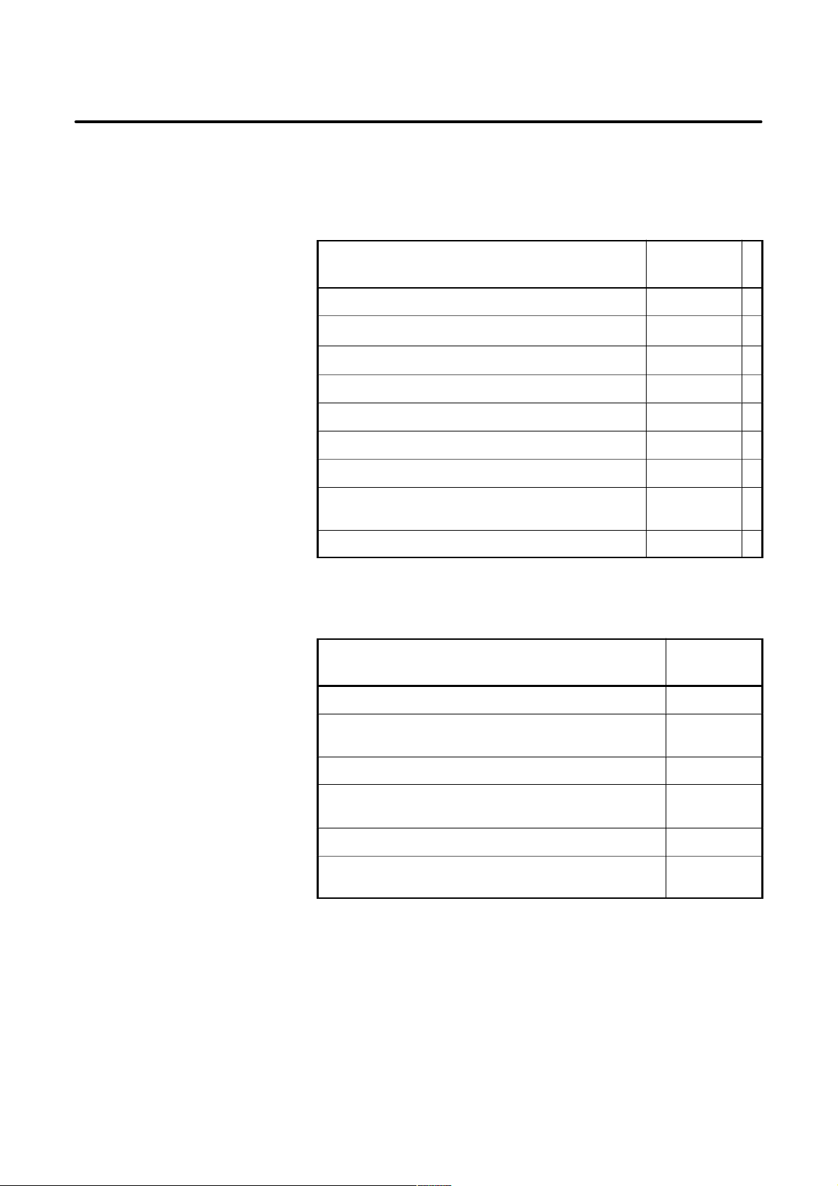
conform to the following table. Section 3.3 describes the installation and
design conditions of a cabinet satisfying these conditions.
In operation 0°C to 45°C
Room temperature
In storage or transportation –20°C to 60°C
Change in
temperature
Relative humidity
Vibration In operation: 0.5G or less
1.1°C /minute max.
Normal 75% or less
T emporary(within 1 month) 95% or less
3.1.2
Installation
Requirements of CNC
and Servo Unit
Normal machine shop environment
Environment
Room temperature
Relative humidity 95% RH or less (no condensation)
Vibration 0.5 G or less
Environment
(The environment must be considered if the cabinets
are in a location where the density of dust, coolant, and/
or organic solvent is relatively high.)
In operation 0°C to +55°C
In storage or transportation –20°C to +60°C
The unit shall not be exposed direct to cutting oil, lubricant or cutting chips.
7
Page 18

3. INSTALLATION
"
3.2
POWER SUPPLY
B–63503EN/01
3.2.1
Power Supply for CNC
Control Units
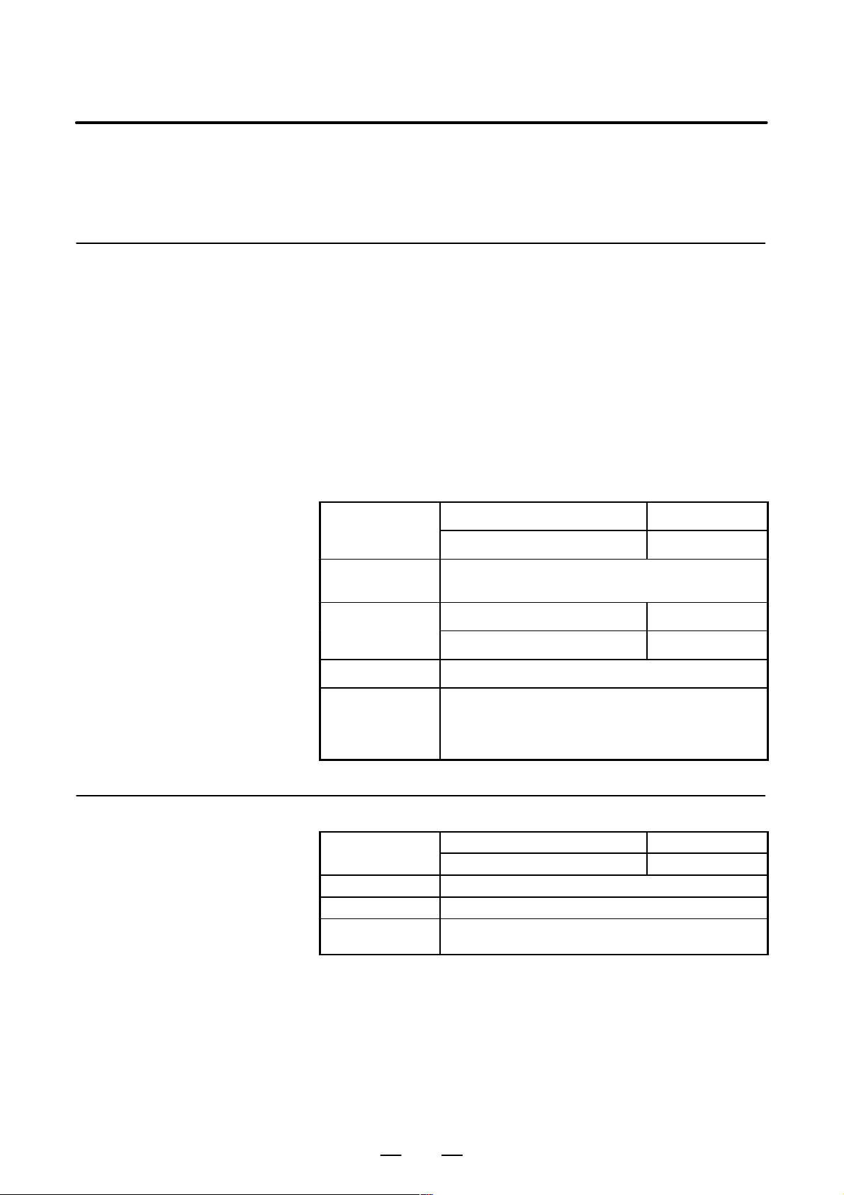
The following units related to the CNC control unit require input power
of 24 VDC "10%.
T able 3.2.1 Power supply
Unit Power supply
0i control unit
9″ CRT/MDI unit
8.4″ TFT color unit
24 VDC"10%
momentary surges
and ripples.
voltage
3.5A (only control unit)
10% includes
0.8A
0.8A
Power supply
8
Page 19

B–63503EN/01
3. INSTALLATION
3.3
DESIGN AND INSTALLATION CONDITIONS OF THE MACHINE TOOL MAGNETIC CABINET
When a cabinet is designed, it must satisfy the environmental conditions
described in Sec. 3.1. In addition, the magnetic interference on the CR T
screen, noise resistance, and maintenance requirements must be
considered. The cabinet design must meet the following conditions :
(1)The cabinet must be fully closed.
The cabinet must be designed to prevent the entry of airborne
dust,coolant,and organic solvent.
Cabinets that let in air may be desined for the servo amplifier and servo
transformer provided that they :
D Use an air filter on the air inlet ;
D Place the ventilating fan so that it does not blow air directly toward
the unit;
D Control the air flow so that no dust or coolant enters the air outlet
(2)The cabinet must be designed to maintain a difference in temperature
of 10°C or less between the air in the cabinet and the outside air when
the temperature in the cabinet increases.
See Sec. 3.4 for the details on thermal design of the cabinet.
(3) A closed cabinet must be equipped with a fan to circulate the air
within.
The fan must be adjusted so that the air moves at 0.5 m/sec along the
surface of each installed unit.
CAUTION
If the air blows directly from the fan to the unit, dust easily
abheres to the unit. This may cause the unit to fail.
(4)For the air to move easily, a clearance of 100 mm is required between
each unit and the wall of the cabinet.
(5) Packing materials must be used for the cable port and the door in
oreder to seal the cabinet.
Because the CRT unit uses a voltage of approximatery 1 1 kV, airborne
dust gathers easily. If the cabinet is insufficiently sealed, dust passes
through the gap and abheres to the unit. This may cause the insulation
of the unit to deteriorate.
(6)The display unit and other display units must be installed in a location
where coolant cannot be poured directly on it. The unit does have a
dust–proof front panel.
(7)Noise must be minimized.
As the machine and the CNC unit are reduced in size, the parts that
generate noise may be placed near noise–sensitive parts in the
magnetics cabinet.
The CNC unit is built to protect it from external noise. Cabinet design
to minimize noise generation and to prevent it from being transmitted
to the CNC unit is necessary. See Sec. 3.5 for details of noise
elimination/management.
(8)The units must be installed or arranged in the cabinet so that they are
easy to inspect and maintain.
9
Page 20

3. INSTALLATION
B–63503EN/01
(9)The CRT screen can be distorted by magnetic interference.
Arranging magnetic sources must be done with care.
If magnetic sources (such as transformers, fan motors,
electromagnetic contactors, solenoids, and relays) are located near the
CRT display, they frequently distort the display screen. To prevent
this, the CRT display and the magnetic sources generatlly must be kept
300 mm apart. If the CRT display and the magnetic sources are not
300 mm apart, the screen distortion may be suppressed by changing
the direction in which the magnetic sources are installed.
The magnetic intensity is not constant, and it is often increased by
magnetic interference from multiple magnetic sources interacting
with each other . As a result, simply keeping the CR T and the magnetic
sources 300 mm apart may not be enough to prevent the distortion.
If they cannot be kept apart, or if the CRT screen remains distorted
despite the distance, cover the screen with a magnetic shield.
10
Page 21

B–63503EN/01
3. INSTALLATION
3.4
THERMAL DESIGN OF THE CABINET
3.4.1
Temperature Rise
Within the Cabinet
The purpose of the thermal design of the cabinet is to limit the difference
in temperature between the air in the cabinet and the outside air to 10°C
or less when the temperature in the cabinet increases.
The internal air temperature of the cabinet increases when the units and
parts installed in the cabinet generate heat. Since the generated heat is
radiated from the surface of the cabinet, the temperature of the air in the
cabinet and the outside air balance at certain heat levels. If the amount
of heat generated is constant, the larger the surface area of the cabinet, the
less the internal temperature rises. The thermal design of the cabinet
refers to calculating the heat generated in the cabinet, evaluating the
surface area of the cabinet, and enlarging that surface area by installing
heat exchangers in the cabinet, if necessary. Such a design method is
described in the following subsections.
The cooling capacity of a cabinet made of sheet metal is generally 6 W/°C
per 1m
cabinet having a surface area of 1 m
cabinet rises by 1°C. In this case the surface area of the cabinet refers to
the area useful in cooling , that is, the area obtained by subtracting the area
of the cabinet touching the floor from the total surface area of the cabinet.
There are two preconditions : The air in the cabinet must be circuited by
the fun, and the temperature of the air in the cabinet must be almost
constant.
The following expression must then be satisfied to limit the difference in
temperature between the air in the cabinet and the outside air to 10°C or
less when the temperature in the cabinet rises:
For example, a cabinet having a surface area of 4m
of 24W/°C. T o limit the internal temperature increase to 10°C under these
conditions, the internal heat must not exceed 240W. If the actual internal
heat is 320W, however, the temperature in the cabinet rises by 13°C or
more. When this happens, the cooling capacity of the cabinet must be
improved using the heat exchanger described next.
2
surface area, that is, when the 6W heat source is contained in a
Internal heat loss P [W] x 6 [W/m
× 10 [°C] of rise in temperature
2
, the temperature of the air in the
2 S
@ °C ] × surface area S [m2]
2
has a cooling capacity
3.4.2
Cooling by Heat
Exchanger
If the temperature rise cannot be limited to 10°C by the cooling capacity
of the cabinet, a heat exchanger must be added. The heat exchanger
forcibly applies the air from both the inside and outside of the cabinet to
the cooling fin to obtain effective cooling. The heat exchanger enlar ges
the surface area.
11
Page 22
3. INSTALLATION
3.4.3
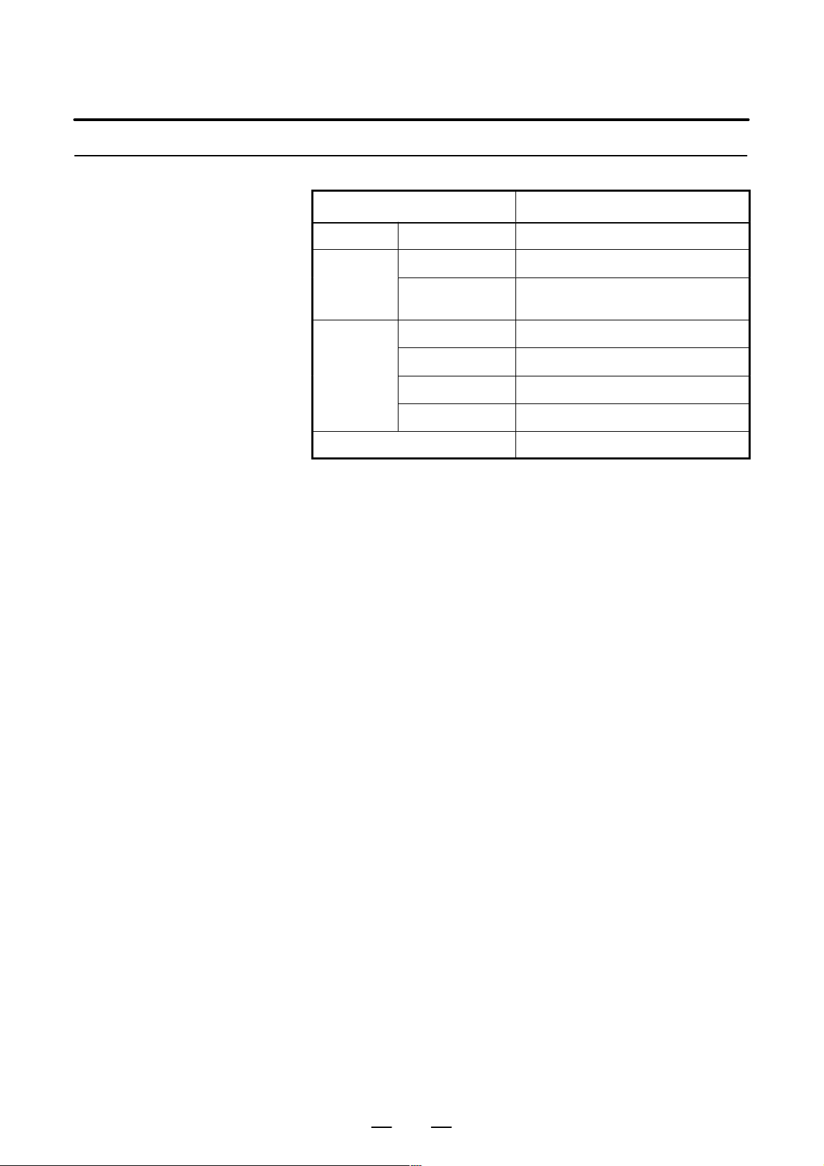
Heat Loss of Each Unit
B–63503EN/01
Name Heat loss
Control unit Series 0i 60W
Display unit
I/O unit
Multi–tap transformer 51W
9″CRT/MDI unit 14W
8.4″LCD/MDI
color unit
AIF01A, AIF01B 1.2W
AID32A, AID32B 1.2W+0.23W number of ON points
AID16C, AID16D 0.1W+0.21W number of ON points
AID32E, AID32F 0.1W+0.23W number of ON points
20W
12
Page 23

B–63503EN/01
3. INSTALLATION
3.5
ACTION AGAINST NOISE
3.5.1
Separating Signal
Lines
The CNC has been steadily reduced in size using surface–mount and
custom LSI technologies for electronic components. The CNC also is
designed to be protected from external noise. However, it is difficult to
measure the level and frequency of noise quantitatively, and noise has
many uncertain factors. It is important to prevent both noise from being
generated and generated noise from being introduced into the CNC. This
precaution improves the stability of the CNC machine tool system.
The CNC component units are often installed close to the parts generating
noise in the power magnetics cabinet. Possible noise sources into the
CNC are capacitive coupling, electromagnetic induction, and ground
loops.
When designing the power magnetics cabinet, guard against noise in the
machine as described in the following section.
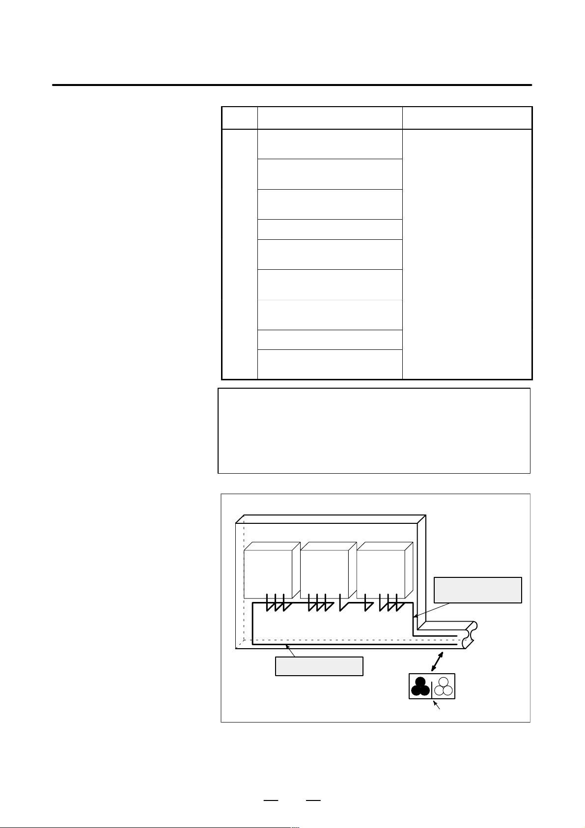
The cables used for the CNC machine tool are classified as listed in the
following table:
Process the cables in each group as described in the action column.
Group Signal line Action
Primary AC power line
Secondary AC power line
AC/DC power lines (containing the
power lines for the servo and
A
spindle motors)
AC/DC solenoid
Bind the cables in group A separately (Note 1) from groups B
and C, or cover group A with
an electromagnetic shield
(Note 2).
See Subsec. 3.5.4 and connect spark killers or diodes with
nect spark killers or diodes with
the solenoid and relay .
AC/DC relay
DC solenoid (24VDC)
DC relay (24VDC)
DI/DO cable between the CNC and
B
power magnetics cabinet
DI/DO cable between the CNC and
machine
Connect diodes with DC solenoid and relay .
Bind the cables in group B separately from group A, or cover
group B with an electromagnetic shield.
Separate group B as far from
Group C as possible.
It is more desirable to cover
group B with the shield.
13
Page 24
3. INSTALLATION
B–63503EN/01
Group ActionSignal line
Cable between the CNC and servo
amplifier
Cable for position and velocity
feedback
Cable between the CNC and
spindle amplifier
Cable for the position coder
Cable for the manual pulse gener-
C
ator
Cable between the CNC and the
CRT/MDI
RS–232–C and RS–422 interface
cable
Cable for the battery
Other cables to be covered with the
shield
Bind the cables in group C
separately from group A, or
cover group C with an electromagnetic shield.
Separate group C as far from
Group B as possible.
Be sure to perfrom shield processing in Subsec. 3.5.5.
NOTE
1 The groups must be 10 cm or more apart from one another
when binding the cables in each group.
2 The electromagnetic shield refers to shielding between
groups with grounded steel plates.
Spindle
amp.
Cabinet
Servo
amp.
Cable of group A
Control
unit
Cable of group B, C
Duct
Section
Group A Group B, C
Cover
To operator’s
panel,
motor , etc.
14
Page 25

B–63503EN/01
3. INSTALLATION
3.5.2
Ground
The following ground systems are provided for the CNC machine tool:
(1)Signal ground system (SG)
The signal ground (SG) supplies the reference voltage (0 V) of the
electrical signal system.
(2)Frame ground system (FG)
The frame ground system (FG) is used for safety, and suppressing
external and internal noises. In the frame ground system, the frames,
cases of the units, panels, and shields for the interface cables between
the units are connected.
(3)System ground system
The system ground system is used to connect the frame ground
systems connected between devices or units with the ground.
Signal ground system
Power
magnetics
unit
Servo
amplifier
CNC
control
unit
Frame ground sysytem
System ground system
Operator’s
panel
Machine
tool
Notes on connecting the
ground systems
Power
magnetics
cabinet
Distribution board
D Connect the signal ground with the frame ground (FG) at only one
place in the CNC control unit.
D The grounding resistance of the system ground shall be 100 ohms or
less (class 3 grounding).
D The system ground cable must have enough cross–sectional area to
safely carry the accidental current flow into the system ground when
an accident such as a short circuit occurs.
(Generally, it must have the cross–sec tional area of the AC power cable
or more.)
D Use the cable containing the AC power wire and the system ground
wire so that power is supplied with the ground wire connected.
15
Page 26

3. INSTALLATION
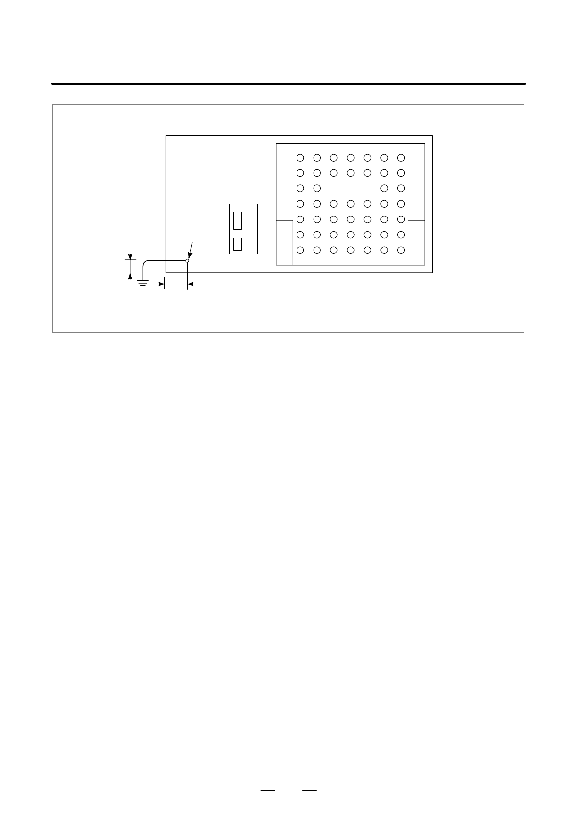
3.5.3
Connecting the Signal
Ground (SG) of the
Control Unit
Control unit
B–63503EN/01
MAIN
STATUS
ALARM
IOL INK
JD 1A
SPDL–1
JA 7A
A–OUT
JA 8A
SERVO1
JS1A
SERVO2
JS2A
SERVO3
JS3A
SERVO4
JS4A
SCALE1
JF21
SCALE2
JF22
SCALE3
JF23
SCALE4
JF24
SC–ABS
JF25
BATTERY
MEMORY
CARD
CNMC
I/O
PSU
4
231
CPS
MPG
JA3B
FUSE75A
PIL
CP1A
CP1B
DCIN
DCOUT
24V
24V
5A
CRT
JA1
MDI
JA2
R232–1
JD5A
R232–2
JD5B
1A
R
L
R
L
RSW1
M3 terminal for
MINI
SLOT
signal ground (SG)
Ground plate
Ground cable
(upper 2mm
Frame
ground
(FG)
FANUC
FA-
NUC
2
)
= Ground plate of
the cabinet
FANUC
M3
Ground cable
System ground
Connect the 0 V line of the electronic circuit in the control unit with the
ground plate of the cabinet via the signal ground (SG) terminal.
The SG terminal is located below the main board of the control unit.
16
Page 27
B–63503EN/01
3. INSTALLATION
MDI
M4 stud
Approx. 15mm
Approx. 20 mm (for 9″ CRT/MDI unit)
Approx. 150 mm (for 8.4″ LCD/MDI unit)
CRT
9″ CRT/MDI unit
8.4″ LCD/MDI unit
17
Page 28

3. INSTALLATION
B–63503EN/01
3.5.4
Noise Suppressor
Notes on selecting the
spark killer
The AC/DC solenoid and relay are used in the power magnetics cabinet.
A high pulse voltage is caused by coil inductance when these devices are
turned on or off.
This pulse voltage induced through the cable causes the electronic circuits
to be disturbed.
D Use a spark killer consisting of a resistor and capacitor in series. This
type of spark killer is called a CR spark killer.(Use it under AC)
(A varistor is useful in clamping the peak voltage of the pulse voltage,
but cannot suppress the sudden rise of the pulse voltage. FANUC
therefore recommends a CR spark killer.)
D The reference capacitance and resistance of the spark killer shall
conform to the following based on the current (I (A)) and DC
resistance of the stationary coil:
1) Resistance (R) : Equivalent DC resistance of the coil
2) Capacitance (C) :
10
2
I
2
I
to
20
(µF)
I : Current at stationary state of the coil
RC
Equivalent circuit of the spark killer
AC
relay
Spark killer
Mount the noise eliminator near a motor or a relay coil.
Spark killer
NOTE
Use a CR–type noise eliminator. Varistor–type noise
eliminators clamp the peak pulse voltage but cannot
suppress a sharp rising edge.
Diode (used for direct–current circuits)
Diode
Use a diode which can withstand a
DC relay
voltage up to two times the applied
voltage and a current up to two times
the applied current.
Motor
18
Page 29
B–63503EN/01
3. INSTALLATION
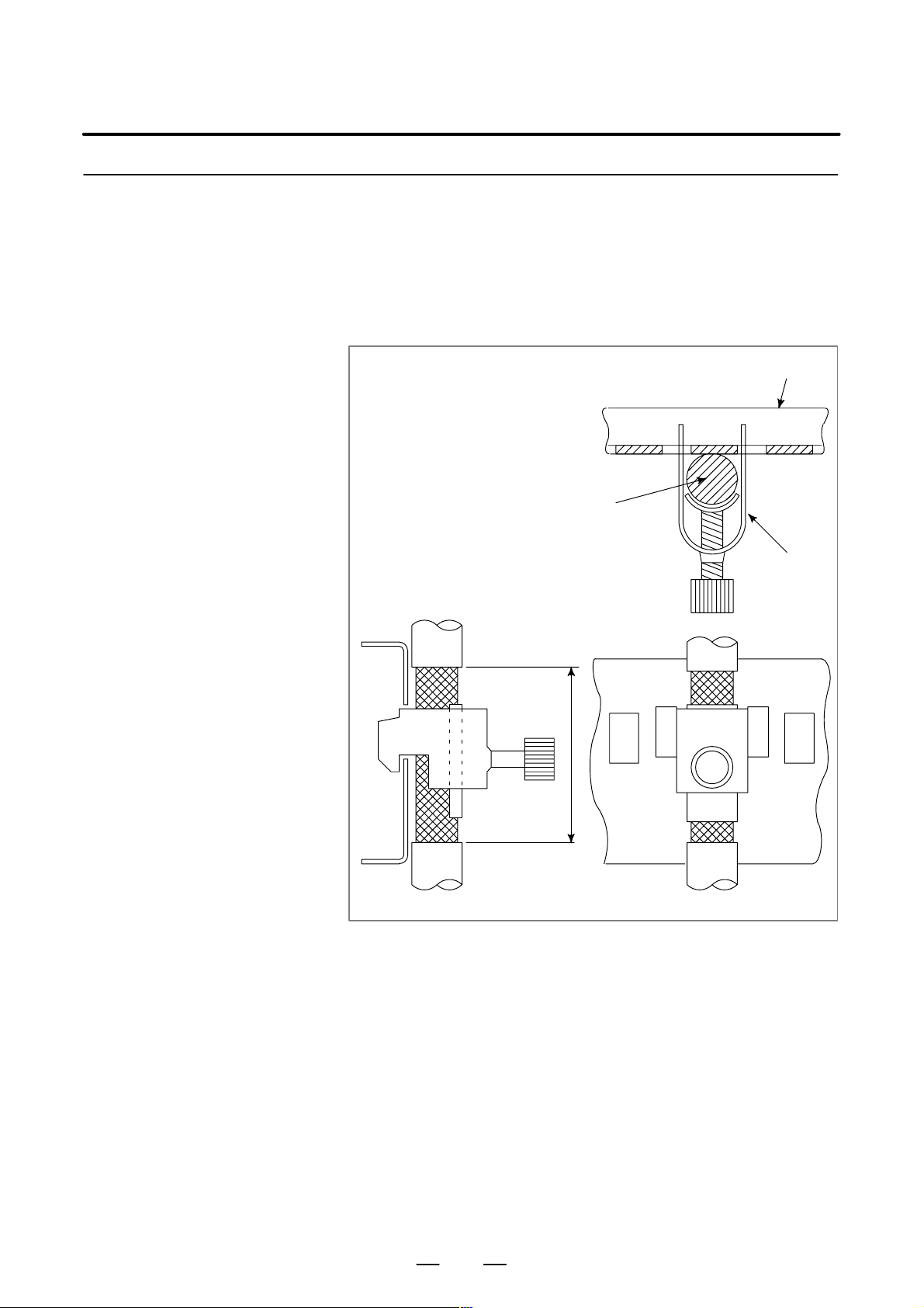
3.5.5
Cable Clamp and
Shield Processing
The CNC cables that require shielding should be clamped by the method
shown below. This cable clamp treatment is for both cable support and
proper grounding of the shield. To insure stable CNC system operation,
follow this cable clamp method.
Partially peel out the sheath and expose the shield. Push and clamp by
the plate metal fittings for clamp at the part. The ground plate must be
made by the machine tool builder, and set as follows :
Ground plate
Cable
Metal fittings
for clamp
40mm – 80mm
Fig.3.5.5(a) Cable clamp (1)
19
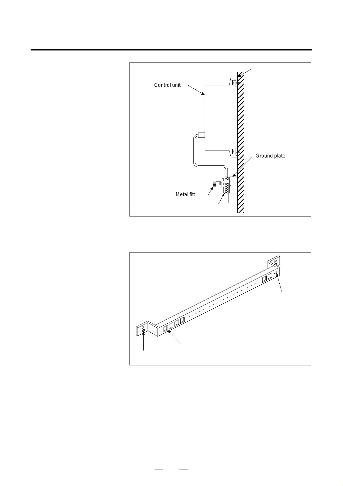
Page 30
3. INSTALLATION
B–63503EN/01
Machine side
installation
board
Control unit
Ground plate
Metal fittings
for clamp
Shield cover
Fig.3.5.5(b) Cable clamp (2)
Prepare ground plate like the following figure.
Ground terminal
(grounded)
Hole for securing metal fitting clamp
Mount screw hole
Fig.3.5.5(c) Ground plate
For the ground plate, use a metal plate of 2 mm or thicker, which surface
is plated with nickel.
20
Page 31

B–63503EN/01
3. INSTALLATION
8mm
12mm
20mm
Fig.3.5.5(d) Ground plate holes
(Reference) Outer drawings of metal fittings for clamp.
Max. 55mm
Ground
plate
6mm
Fig.3.5.5(e) Outer drawings of metal fittings for clamp
Ordering specification for metal fittings for clamp
A02B–0124–K001 (8 pieces)
28mm
17mm
21
Page 32

3. INSTALLATION
3.6
CONTROL UNIT
B–63503EN/01
3.6.1
Installation of the
Control Unit
The rack consists of a plastic box, fan motors and a backplane PCB. The
air comes into the rack from the bottom and goes out through the fan
motor, which is located on the top of the rack. Space as shown in Fig.
3.6.1 must be reserved not to disturb the air flow ((A), (B))
The backplane PCB, which is located on the rear side of the rack,
interconnects the PCBs installed in the rack. It has another connector
which appears at the left side panel of the rack. This connector is used for
testing the controller, connecting other purposes. The space for this shall
be reserved as shown in (C) of Fig. 3.6.1.
AIR FLOWAIR FLOW
Reserved
Reserved
(C)
(A)
50
(A)
250
30
(B)
Reserved
Fig.3.6.1
50
(B)
172
Unit : mm
22
Page 33

B–63503EN/01
3. INSTALLATION
3.7
CABLE LEAD–IN DIAGRAM
Fig. 3.7 (a) shows the grid of connector location.
Control board may not have all connectors as shown in Fig. 3.7 (a).
For actual connector layout of each board, please see the connector layout
diagrams in Fig. 3.8 (a) or later.
8
1732350392545 25
36
745864386086
129
35
Main board I/O board
52
1452
9
Fig.3.7 (a)
23
Page 34

3. INSTALLATION
B–63503EN/01
Memory
card
(80)
172
Unit : mm
Fig.3.7 (b)
24
Page 35

B–63503EN/01
3.8
CONNECTOR LAYOUT DIAGRAM
3. INSTALLATION
LED display Connector name and comment
Function Upper Lower
LED STATUS/ALARM
Battery for memory CPB
Battery BATTERY
Memory card MEMORY/CARD CNMC
Rotary switch RSW1
for maintenance
Serial I/O Link IOLINK JD1A
Serial spindle SPDL–1 JA7A
Analog output A–OUT1 JA8A
Servo amp.1 SERVO1 JS1A
Servo amp.2 SERVO2 JS2A
Servo amp.3 SERVO3 JS3A
Servo amp.4 SERVO4 JS4A
Linear scale1 SCALE1 JF21
Linear scale2 SCALE2 JF22
Linear scale3 SCALE3 JF23
Linear scale4 SCALE4 JF24
APC battery for SC–ABS JF25
linear scale
Fig.3.8 (a) Main board
25
Page 36

3. INSTALLATION
B–63503EN/01
Connector name and comment
Function Upper Lower
Position
1 Serial port R232–1 JD5A
2 Fuse FUSE
3
4 Pilot lamp PIL
5 24VDC output (R side) DC OUT CP1B
6 24VDC input (L side) DC IN CP1A
7 Operator’s panel I/O (R side) DI/DO–1 CB104
8 Machine side I/O (L side) DI/DO–2 CB105
R
L
9
10 CRTdisplay CRT JA1
1 1 MDI MDI JA2
12 Serial port R232–2 JD5B
13 Manual pulse generator MPG JA3
14
15 Machine side I/O (R side) DI/DO–3 CB106
16 Machine side I/O (L side) DI/DO–4 CB107
R
L
17
18
19
20
21
Fig.3.8 (b) I/O board
26
Page 37

B–63503EN/01
3. INSTALLATION
Function Comment
Mode switch
LED display
High–speed serial
bus interface
Fig.3.8 (c) High–speed serial bus interface board
SW
ST– 4 3 2 1
AL– 1 2
COP7
27
Page 38

4. POWER SUPPLY CONNECTION
POWER SUPPLY CONNECTION
4
B–63503EN/01
28
Page 39

B–63503EN/01
4. POWER SUPPLY CONNECTION
4.1
GENERAL
This section explains the connection of power supply for Series 0i control
unit.
29
Page 40

4. POWER SUPPLY CONNECTION
4.2
TURNING ON AND OFF THE POWER TO THE CONTROL UNIT
B–63503EN/01
4.2.1
Power Supply for the
Control Unit
Main
breaker
200VAC
Magnetic
contactor
Supply power (24VDC) to the control uint of Series 0i from an external
sources.
Install a power switch at (1) in Fig. 4.2.1 (a).
AC line
filter
External
24VDC
power
Servo unit
PSM
Input
3f
200VAC
For control line
1f
200VAC
(1)
SVM
ON/OFF circuit
Series 0i
control unit
24VDC
Input
24VDC
Output
9″CRT or
8.4″LCD
unit
Fig.4.2.1 (a)
30
ON OFFCOM
Page 41

B–63503EN/01
4. POWER SUPPLY CONNECTION
ON/OFF circuit (example)
G
+24V
DC INPUT
24V 4A
0V 0V
OFF COM ON
For example, “ON/OFF circuit” is as follows : (Fig.4.2.1 (b) )
Select the circuit devices, in consideration of its capacity.
G
lc3
+24V
DC OUTPUT
RY1 LC3
ry1
ry1
SERGE
ABSORBER
24V 4A
SPARK
KILLER
POWER ON/OFF SWITCH
OFF ON
Fig.4.2.1 (b)
DIODE
RELAY
COIL
B CONT ACT
FUSE
RELAY
CONTACT
A CONT ACT
31
Page 42

4. POWER SUPPLY CONNECTION
B–63503EN/01
4.2.2
+24 V Input Power
Specifications
Recommended connection and recommended power specifications
(1)Recommended connection
AC input
Regulated
power
supply
CNC
unit
(2)Recommended power specifications
(Must conform to the applicable safety standard.)
Output voltage: +24 V "10% (21.6 V to 26.4 V)
(including ripple voltage and noise. See the figure
below.)
Output current: The continuous load current must be larger than
the current consumption of the CNC (at the
maximum allowable temperature in the power
magnetics cabinet in which the power supply is
located).
Output retention time in the event of an instantaneous input
interruption:
10 mS (in the event of a drop by 100%)
20 mS (in the event of a drop by 50%)
AC input voltage
26.4V
Output voltage
21.6V
Output current
0A
Instantaneous
interruption
(–100%)
10mS 20mS
Fig. Examples of ripple voltage and noise due to switching power supply
Instantaneous
interruption
(–50%)
Abrupt
load
change
Noise
Ripple
voltage
Noise
Fig.4.2.2 Timing Chart
32
Page 43

B–63503EN/01
4. POWER SUPPLY CONNECTION
D Circuit configurations
Circuit configurations such as those shown below are not recommended.
a) Circuit examples in which the output voltage cannot be retained in the
event of an instantaneous interruption (the voltage decreases to 21.6
V or below)
Example 1
AC input
circuit
Rectifying
CNC unit
Example 2
AC input
circuit
Rectifying
CNC unit
b) Circuit examples that exceed the output voltage specification (21.6 V
to 26.4 V) due to an abrupt load change
Example 1
AC input
Example 2
AC input
Regulated
power
supply
Regulated
power
supply
CNC unit
Unit with
considerable load
fluctuations
CNC unit
Unit with
large rush
current
33
Page 44

4. POWER SUPPLY CONNECTION
B–63503EN/01
4.2.3
Procedure for Turning
On the Power
Turn on the power to each unit in the following order or all at the same
time.
1. Power supplies (200 VAC) for the entire machine
2. Power supplies (24 VDC) for slave I/O devices connected
using the FANUC I/O Link
3. Power supplies (24 VDC) for the control unit and CRT unit
Do not disconnect the battery for memory backup (3 VDC) or the battery
for the separate absolute pulse coders (6 VDC) regardless of whether the
power to the control unit is on or off. If batteries are disconnected when
the power to the control unit is turned off, current data stored in the control
unit for the pulse coders, parameters, programs etc, are lost.
Make sure that the power to the control unit is on when replacing batteries.
See Section 4.4.1 for how to replace the batteries for memory backup.
CAUTION
The maintenance rotary switch must be always set to 0 (set
to 0 at shipping from factory).
Changing this setting may cause the contents of memory to
be lost.
4.2.4
Procedure for Turning
Off the Power
Turn off the power to each unit in the following order or all at the same
time.
1. Power supplies (24 VDC) for slave I/O devices connected
using the FANUC I/O Link
2. Power supplies (24 VDC) for the control unit and CRT unit
3. Power supplies (200 VAC) for the entire machine
Motors cannot be controlled when the power is turned off or momentarily
interrupted. Take appropriate action on the machine side when necessary .
For example, when the tool is moved along a gravity axis, apply brakes
to prevent the axis from falling. Apply a brake that clamps the motor
when the servo is not operating or the motor is not rotating. Release the
clamp only when the motor is rotating. When the servo axis cannot be
controlled when the power is turned off or momentarily interrupted,
clamp the servo motor . In this case, the axis may fall before the relay for
clamping starts operating. The designer should make sure if the distance
results in trouble.
34
Page 45

B–63503EN/01
4. POWER SUPPLY CONNECTION
4.3
CABLE FOR POWER SUPPLY TO CONTROL UNIT
Supply power to the control unit from external resouce.
Series 0i control unit
CP1A
13+24V
2
Cable
CP1A
AMP Japan
1–178288–3 (housing)
1–175218–5 (Contact)
Recommended cable : A02B–0124–K830 (5m)
(Crimp terminal of size M3 is available on the external power side)
0V
+24V (1)
0v (2)
External power
24VDC stabilized
power
24VDC "10%
External power
Select a source that
meets the external
power terminal.
35
Page 46

4. POWER SUPPLY CONNECTION
4.4
BATTERY
B–63503EN/01
4.4.1
Battery for Memory
Backup (3VDC)
Part programs, offset data, and system parameters are stored in CMOS
memory in the control unit. The power to the CMOS memory is backed
up by a lithium battery mounted on the front panel of the control unit. The
above data is not lost even when the main battery goes dead. The backup
battery is mounted on the control unit at shipping. This battery can
maintain the contents of memory for about a year.
When the voltage of the battery becomes low, alarm message “BAT”
blinks on the CRT display and the battery alarm signal is output to the
PMC. When this alarm is displayed, replace the battery as soon as
possible. In general, the battery can be replaced within two or three
weeks, however, this depends on the system configuration.
If the voltage of the battery becomes any lower, memory can no longer
be backed up. T urning on the power to the control unit in this state causes
system alarm 910 (SRAM parity alarm) to occur because the contents of
memory are lost. Clear the entire memory and reenter data after replacing
the battery.The power to the control unit must be turned on when the
battery is replaced. If the battery is disconnected when the power is turned
off, the contents of memory are lost.
Observe the following precautions for lithium batteries:
WARNING
If an unspecified battery is used, it may explode.
Replace the battery only with the specified battery
(A02B–0177–K106.)
Replacing the battery
Dispose of batteries used in accordance with the applicable laws of your
country or the applicable laws or regulations of your local self–governing
body. Before disposal, insulate the terminals with tape or something
similar to prevent them from being short–circuited.
1 Use a litium battery (ordering drawing number :
A02B–0177–K106)
2 Turn on the Series 0i.
3 Remove the battery case from the front panel of the power supply unit.
The case can be removed easily by holding the top and bottom of it and
pulling.
36
Page 47

B–63503EN/01
4. POWER SUPPLY CONNECTION
Front panel of control
unit main board
MAIN
STATUS
ALARM
Battery case
BATTERY
Battery (Ordering drawing
number A02B–0177–K106)
Fig.4.4.1(a) Replacing the battery(1)
4 Remove the connector from the battery.
Front panel of control
unit main board
CP8
231
MEMORY
CARD
CNMC
4
CP8
Battery connector
RSW1
Battery connector
BATTERY
MEMORY
CARD
CNMC
Fig.4.4.1(b) Replacing the battery(2)
5 Replace the battery and reconnect the connector.
6 Install the battery case.
7 Turn off the Series 0i.
37
Battery
Page 48

4. POWER SUPPLY CONNECTION
B–63503EN/01
4.4.2
Battery for Separate
Absolute Pulse Coders
(6VDC)
One battery unit can maintain current position data for six absolute pulse
coders for a year.
When the voltage of the battery becomes low , APC alarms 3n6 to 3n8 (n:
axis number) are displayed on the CRT display. When APC alarm 3n7
is displayed, replace the battery as soon as possible. In general, the battery
should be replaced within two or three weeks, however, this depends on
the number of pulse coders used.
If the voltage of the battery becomes any lower , the current positions for
the pulse coders can no longer be maintained. Turning on the power to
the control unit in this state causes APC alarm 3n0 (reference position
return request alarm) to occur. Return the tool to the reference position
after replacing the battery .See Subsec. 7.1.3 for connecting the battery for
separate absolute pulse coders.
38
Page 49

B–63503EN/01
5
5. CONNECTION TO CNC PERIPHERALS
CONNECTION TO CNC PERIPHERALS
39
Page 50

5. CONNECTION TO CNC PERIPHERALS
5.1
CONNECTION T O THE DISPLAY UNIT
B–63503EN/01
5.1.1
Outline
The display unit is used for displaying the programs, parameters etc, and
supporting the machine operation.
The Series 0i supports the following display units: 9″ CRT and 8.4″ LCD.
40
Page 51

B–63503EN/01
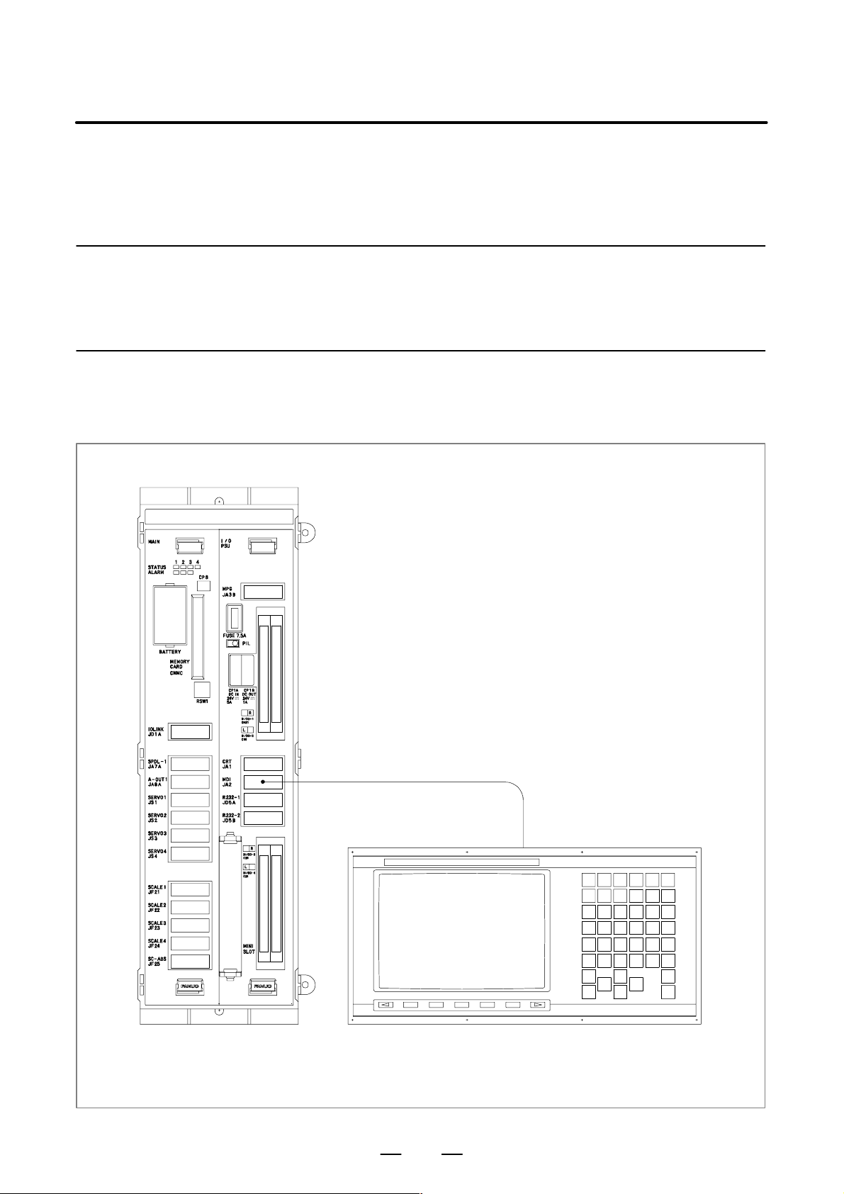
5.1.2
Connection to Display
Unit
Connection to Series 0i
Control unit
5. CONNECTION TO CNC PERIPHERALS
CP1B
DC OUT
Power supply cable
CRT
JA1
Video cable
CN2 (CRT)
CP5 (LCD)
CRT/MDI, LCD/MDI unit
CN1 (CTR)
JA1 (LCD)
41
Page 52

5. CONNECTION TO CNC PERIPHERALS
5.1.3
9″ CRT Display Unit
Interface
Series 0i CRT unit
B–63503EN/01
JA1
(PCR–EV20MDT)
VDR
01
0V
02
03
VDG
04
0V
05
VDB
06
0V
07
08
09
10
CP1B
Cable side
JAPAN AMP
2–178288–3 (Housing)
1–175218–5 (contact)
Connection of
VIDEO Signal Cable
JA1
HIROSE FI40A–20S–CV5 (Connector)
11
12
13
14
15
16
17
18
19
20
1
2
3
VSYNC
0V
0V
HSYNC
+24V
0V
CN1
(MR–20RM)
1
VDR
2
HSYNC
3
VSYNC
4
VDG
5
VDB
6
7
1
2
3
(0V)
4
0V
5
+24V
6
(+24V)
0V
8
0V
9
0V
10
0V
11
0V
12
13
CN2
Cable side
JAPAN FCI
SMS6PN–5 (Housing)
RC16M–23TB or RC16M
(contact)
CN1
HONDA MR20pins/female
14
15
16
17
18
19
20
(0V)
(0V)
VDR (01)
0V (02)
VDG (03)
0V (04)
VDB (05)
0V (06)
HSYNC (18)
0V (16)
VSYNC (12)
0V (14)
RECOMMENDED CABLE MA TERIAL
A66L–0001–0371 COAXIAL CABLE (MAX : 50m)
RECOMMENDED CABLE MA TERIAL
A02B–0120–K819 CRT VIDEO SIGNAL CABLE (5m)
(01) VDR
(08) 0V
(04) VDG
(1 1) 0V
(05) VDB
(12) 0V
(02) HSYNC
(09) 0V
(03) VSYNC
(10) 0V
42
Page 53

B–63503EN/01
5.1.4
8.4″ LCD Units
Interface
Series 0i LCD unit
5. CONNECTION TO CNC PERIPHERALS
JA1
(PCR–HV20MDT)
01
VDR
02
0V
03
VDG
04
0V
05
VDB
06
0V
07
08
09
10
CP1B
Cable side
Housing: JAPAN AMP 2–178288–3
Contact : JAPAN AMP 1–175218–5
Connection of
VIDEO Signal Cable
JA1
HIROSE FI40A–20S–CV5 (Connector)
11
12
13
14
15
16
17
18
19
20
1
2
3
VSYNC
0V
0V
HSYNC
(+24V)
(0V)
JA1
(PCR–HV20MDT)
01
02
03
04
05
06
07
08
09
10
1
2
3
VDR
0V
VDG
0V
VDB
0V
(+24V)
(0V)
11
12
13
14
15
16
17
18
19
20
CP5
Cable side
Housing: JAPAN AMP 2–178288–3
Contact : JAPAN AMP 1–173218–5
VSYNC
0V
0V
HSYNC
JA1
HIROSE FI40A–20S–CV5
(Connector)
VDR (01)
0V (02)
VDG (03)
0V (04)
VDB (05)
0V (06)
HSYNC (18)
0V (14)
VSYNC (12)
0V (16)
RECOMMENDED CABLE MA TERIAL
A66L–0001–0371 COAXIAL CABLE (MAX : 50m)
RECOMMENDED CABLE MA TERIAL
A02B–0120–K818 LCD/VIDEO SIGNAL CABLE (5m)
(01) VDR
(02) 0V
(03) VDG
(04) 0V
(05) VDB
(06) 0V
(18) HSYNC
(16) 0V
(12) VSYNC
(14) 0V
43
Page 54

5. CONNECTION TO CNC PERIPHERALS
B–63503EN/01
5.1.5
Adjusting the TFT
Color LCD
(1)Applied unit
Name Specification number
8.4″ color LCD/MDI unit A02B–0279–C081#TA
A02B–0279–C081#MA
(2)Adjustment point (as viewed from the rear of the display unit
TM1
SW1
(3)Adjustment method
(a)Display horizontal setting
D The horizontal position of the display is set as described below ,
using SW1. Rotating SW1 one notch in the positive (+)
direction shifts the display one dot to the right. Rotating SW1
one notch in the negative (–) direction shifts the display one dot
to the left.
D Set SW1 such that the entire display is visible. There is only one
optimum setting position.
(b)Flickering adjustment
Flickering is eliminated by setting jumper pin TM1. One side of
TM1 is marked A, while the other side is marked B. TM1 is
factory–set to the B position. If the screen flickers, set TM1 to the
A position.
44
Page 55
B–63503EN/01
5.2
CONNECTION OF MDI UNIT
5. CONNECTION TO CNC PERIPHERALS
5.2.1
General
5.2.2
Connection to the MDI
Unit
Control unit
Manual data input devices for the Series 0i are called MDI units. MDI
units are keyboards used to enter data such as CNC programs and
parameters into the CNC.
MDI
JA2
MDI CABLE
Connection to the MDI
CK1
CRT/MDI unit
LCD/MDI unit
45
Page 56

5. CONNECTION TO CNC PERIPHERALS
5.2.3
Connection to the
Standard MDI Unit
B–63503EN/01
MDI unitSeries 0i control unit
JA2
:KEY01
:KEY00
01
02
:KEY02
03
:KEY04
04
:KEY06
05
:COM00
06
:COM02
:COM04
07
08
:COM06
09
:COM08
10
:COM10
Cable
JA2
Honda PCR connector
11
:KEY03
12
:KEY05
13
:KEY07
14
:COM01
15
:COM03
16
:COM05
17
18
:COM07
:COM09
19
:COM11
20
:KEY00 (01)
:KEY02 (02)
:KEY04 (03)
:KEY06 (04)
:COM00 (05)
:COM02 (06)
:COM04 (07)
:COM06 (08)
:COM08 (09)
:COM10 (10)
:KEY01 (1 1)
:KEY03 (12)
:KEY05 (13)
:KEY07 (14)
:COM01 (15)
:COM03 (16)
:COM05 (17)
:COM07 (18)
:COM09 (19)
:COM1 1 (20)
CK1
:KEY01
:KEY00
01
02
:KEY02
03
:KEY04
04
:KEY06
05
:COM00
06
:COM02
:COM04
07
08
:COM06
09
:COM08
10
:COM10
CK1
Honda PCR connector
(01) :KEY00
(02) :KEY02
(03) :KEY04
(04) :KEY06
(05) :COM00
(06) :COM02
(07) :COM04
(08) :COM06
(09) :COM08
(10) :COM10
(11) :KEY01
(12) :KEY03
(13) :KEY05
(14) :KEY07
(15) :COM01
(16) :COM03
(17) :COM05
(18) :COM07
(19) :COM09
(20) :COM11
11
:KEY03
12
:KEY05
13
:KEY07
14
:COM01
15
:COM03
16
:COM05
17
:COM07
18
:COM09
19
:COM11
20
GROUND
PLATE
RECOMMENDED CABLE SPECIFICA TION : A02B–0120–K810 (5m)
RECOMMENDED CABLE MA TERIAL : A66L–0001–0284#10P (#28AWG 10pair)
SHIELD
46
Page 57
B–63503EN/01
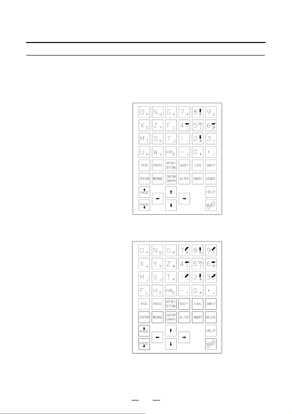
5.2.4
V aried MDI Key Switch
D 9″ CRT/MDI unit and
8.4″ LCD/MDI unit for
Series 0i–TA
English display
5. CONNECTION TO CNC PERIPHERALS
D 9″ CRT/MDI unit and
8.4″ LCD/MDI unit for
Series 0i–MA
English display
47
Page 58

5. CONNECTION TO CNC PERIPHERALS
5.3
CONNECTING I/O DEVICES
B–63503EN/01
5.3.1
General
I/O devices are used for inputting various data such as CNC programs and
parameters from external devices to the CNC or outputting data from the
CNC to external devices.
The Handy File is one of the I/O devices for the Series 0i. The interface
for I/O devices complies with RS–232–C. The Series 0i can therefore be
connected to devices which have an RS–232–C interface.
48
Page 59

B–63503EN/01
5.3.2
Connecting I/O Devices
Control unit
5. CONNECTION TO CNC PERIPHERALS
Punch panel
R232–1
JD5A
R232–2
JD5B
Handy File
49
Page 60

5. CONNECTION TO CNC PERIPHERALS
5.3.3
RS–232–C Serial Port
CNC
JD5A, JD5B
(PCR–EV20MDT)
RD
1
0V
2
DR
3
0V
4
CS
5
0V
6
CD
7
0V
8
9
+24V
10
11
12
13
14
15
16
17
18
19
20
SD
0V
ER
0V
RS
0V
+24V
B–63503EN/01
RELA YING CONNECTOR
(DBM–25S)
FG
10
11
12
13
1
2
SD
RD
3
RS
4
5
CS
DR
6
SG
7
8
CD
9
14
15
16
17
18
19
20
21
22
23
24
25
ER
+24V
CABLE WIRING
1
RD
2
0V
3
DR
4
0V
5
CS
6
0V
7
CD
8
0V
9
10
+24V
11
SD
12
0V
13
ER
14
0V
15
RS
16
0V
17
18
19
+24V
20
SHIELD
GROUND PLA TE
RECOMMENDED CABLE MA TERIAL
A66L–0001–0284#10P(#28AWG 10–pair)
RECOMMENDED CABLE SPECIFICA TION (PUNCH P ANEL)
<Narrow width type>
A02B–0120–C191 (1m)
A02B–0120–C192 (2m)
A02B–0120–C193 (5m)
<Wide width type>
A02B–0120–C181 (1m)
A02B–0120–C182 (2m)
A02B–0120–C183 (5m)
20
25
GND
3
6
5
8
2
4
7
1
RD
DR
CS
CD
SD
ER
RS
SG
+24V
50
Page 61

B–63503EN/01
5.3.4
RS–232–C Interface
Specification
5. CONNECTION TO CNC PERIPHERALS
RS–232–C Interface
signals
Generally signals as follows are used in RS–232–C interface.
CNC
Output
Input
SD (Send data)
RD (Recieve data)
RS (Request to Send)
CS (Enable to send)
ER (Ready)
DR (Data set ready)
CD (Check data)
SG (Signal ground)
When CS is not used
short CS and RS.
When DR is not
used short DR
and ER.
Always short
ER and CD.
FG (Frame ground)
Fig.5.3.4 RS–232–C interface
51
Page 62

5. CONNECTION TO CNC PERIPHERALS
B–63503EN/01
Signal description of
RS–232–C interface
Signal
name
RS–232–C
circuit
number
SD 103 Output Sending
RD 104 Input Receiv-
RS 105 Input Sending
CS 106 Input Sending
DR 107 Input Data set
I/O Description
data
ing
data
request
permitted
ready
Start bit Stop bit
ON
OFF
This signal is set to on when NC
starts sending data and is turned off
when transmission ends.
When both this signal and the DR
signal are set, the NC can send data.
If external device processing is
delayed by a punching operation,
etc., NC data sending can be
stopped by turning off this signal after
sending two characters, including the
data being sent currently. If this signal
will not be used, make sure to strap
this signal circuit to the RS signal circuit.
When external device is ready to operate, this signal is set. This signal
should usually be connected to the
signal indicating external device power supply being on. (ER signal of external device). See Note below.
The NC transfers data when this signal is set. If the signals turned off during data transfer , alarm 086 is issued.
If the DR signal will not be used,
make sure to strap this signal circuit
to the ER signal circuit.
123 8567
(When ISO code “0” is sent)
4
ER 108.2 Output NC ready
to
operation
CD 109 Input Signal
quality
signal
SG 102 Signal
grounding
FG 101 Frame
grounding
This signal is set when the NC is
ready to operate. External device
should regard the SD signal as being
significant when the ER signal is set.
Since this signal is not used in connections with external device, the signal circuit must be strapped, inside
the connecting cable, to the ER signal circuit.
NOTE
Signal on/off state is defined as follows;
–3V or lower
Function
Signal Condition
52
OFF
Marking
+3V or higher
ON
Spacing
Page 63

B–63503EN/01
Transmission Method of
RS–232–C interface
5. CONNECTION TO CNC PERIPHERALS
Start–stop
Codes
Generally , two transmission methods are available at the serial interface.
Series 0i use the start–stop method. With this method, start and stop
signals are output before and after each data bit.
One character in start–stop
b1 b2 b3 b4 b5 b6 b7 b8
Start
bit
(8 bit including one parity bit)
Data bit
Stop bits
(2 bits)
Transmission codes are as follows:
(i) EIA code and Control codes DC1 to DC4.
(ii) ISO code and Control codes DC1 to DC4 (Optional ISO code input
is necessary.)
The connected external device must be able to recognize the following
control codes, sent from NC.
Control code 8 7 6 5 4 3 2 1
DC1 Tape reader start f d f
DC2 Tape punch designation f d f
DC3 Tape reader stop f f d f
DC4 Tape punch release f d f f
NOTE
The listed control codes are used for both EIA and ISO.
In this interface, control codes DC1 to DC4 are used.
(a) NC can control external device by issuing codes DC1 to DC4.
(b) When external processing falls behind the pace of the NC signals
(When NC issues data)
(i) External device can temporarily stop NC data output by using
the NC’s CS signal. Data output stops within two characters
including a currently transmitting character when CS OFF
signal is input to NC. When CS signal is turned on again, data
transmission start.
(ii) If control code DC3 is input to NC, NC stops data output within
ten characters. When control code DC1 is input to NC, NC
starts sending data again.
(c) When the external device is equipped with an ISO/EIA converter,
the external device must satisfy the specification shown in Table
5.3.4 (a).
53
Page 64

5. CONNECTION TO CNC PERIPHERALS
B–63503EN/01
T able 5.3.4(a)
ISO code EIA code
Character
8 7 6 5 4
0 f f
1 f f f
2 f f f
3 f f
4 f f f
5 f f
6 f f
7 f f f
8 f f f f
9 f f f
A f
B f
C f f
D f
E f f
F f f
G f
H f f
I f f f
J f f f
K f f
L f f f
M f f
N f f
O f f f
P f f
Q f f f
R f f f
S f f
T f f f
U f f
3 2 1
F
F
F
F
F
f 4 F f Numeral 4
F
f f 5 f F f f Numeral 5
F
f f 6 f F f f Numeral 6
F
f f f 7 F f f f Numeral 7
F
F
F
F
F
F
f d f f F f Address D
F
f f e f f f F f f ? Address E
F
f f f f f f F f f Address F
F
f f f g f f F f f f Address G
F
F
F
F
F
f l f F f f Address L
F
f f m f f F f Address M
F
f f n f F f f Address N
F
f f f o f F f f
F
F
F
F
F
f t f F f f Address T
F
f f u f f F f Address U
Character
8 7 6 5 4 3 2 1
0 f F Numeral 0
f 1 F f Numeral 1
f 2 F f Numeral 2
f f 3 f F f f Numeral 3
8 f F Numeral 8
f 9 f f F f Numeral 9
f a f f F f Address A
f b f f F f Address B
f f c f f f F f f Address C
h f f f F Address H
f i f f f f F f Address I
f j f f F f Address J
f f k f f F f Address K
Not used at significant data zone in ISO
code.
Assumed as address 0 at EIA code.
p f f F f f f Address P
f q f f f F Address Q
f r f f F f Address R
f f s f f F f Address S
V f f F f f v f F f f Address V
W f f f F f f f w f F f f Address W
X f f f f F x f f F f f f Address X
Y f f f F f y f f f F Address Y
Z f f f F f z f f F f Address Z
DEL f f f f f F f f f Del f f f f F f f f : Delete (cancel erroneous hole)
NUL F Blank F :
No holes. Not used at significant data
zone is EIA code.
BS f f F BS f f F f : Back space
HT f F f Tab f f f F f f : Tabulator
LF or NL f F f CR or EOB f F End of block
CR f f F f f : Carriage return
SP f f F SP f F : Space
% f f F f f ER f F f f Absolute rewind stop
( f f F ( 2–4–5 ) f f F f Control out (start of comment)
) f f f F f ( 2–4–7 ) f f F f Control in (end of comment)
+ f f F f f + f f f F : Plus sign
– f f F f f – f F – Minus sign
: f f f F f Assumed as program number in ISO code.
/ f f f F f f f / f f F f Optional block skip
. f f F f f . f f f F f f Decimal point
# f f F f f : Sharp
$ f F f : Dollar symbol
& f f F f f & f F f f : Ampersand
’ f F f f f : Apostrophe
: f f f F f : Asterisk
, f f f F f , f f f F f f : Comma
; f f f f F f f : Semicolon
< f f f F f : Left angle bracket
= f f f f F f f : Equal mark
> f f f f F f f : Right angle bracket
? f f f F f f f : Question mark
@ f f F : Commerical at mark
” f F f : Quotation mark
Meaning
54
Page 65

B–63503EN/01
5. CONNECTION TO CNC PERIPHERALS
NOTE
1 When the external device is equipped with an ISO/EIA
converter, the following items must be noted in Table
5.3.4(a).
Control out (Comment field start)
Control in (Comment field end)
EIA code (.......................)
Condition1 Condition1
ISO code (.......................)
Condition1
Left parenthesis “(”of the ISO code punches holes at bits 2, 4, and 5
when used in the EIA code.
Right parenthesis “)”of the ISO code punches holes at bits 2, 4, and 7
when used in the EIA code.
Condition2
LF
EIA code is in ISO code.
Condition3
EIA code O is : in ISO code.
CR
CR
Condition2 Condition3
LF
o ....................
: ....................
NOTE
2 Control codes DC1 to DC4 are transmission codes output
from the NC. So they need not to be punched on the NC
tape.
(iii) Transmission rate (Baud rate)
The transmission rate (Baud rate) is the number of bits transferred
per second.
The following baud rates are available depending on the system
parameter.
50, 100, 110, 150, 200, 300, 600, 1200, 2400, 4800, 9600.
(Example)
Baud rate : 110
When using one start bit and two stop bits (totalling 11 bits
per character):
110
Transmission characters/second=
=10 characters/second
11
(Max.)
55
Page 66

5. CONNECTION TO CNC PERIPHERALS
(iv) Cable length
Time chart when the NC
receives data
(Read into memory)
(1) NC outputs DC1.
(2) The external device starts sending data upon receiving DC1.
(3) NC sends DC3 when NC processing is delayed.
(4) The external device stops sending data to NC after receiving DC3.
(5) NC reissues DC1 upon completing delayed processing.
(6) The external device restarts data output upon receiving the DC1
(7) NC sends DC3 upon completing data read.
(8) The external device stops sending data.
B–63503EN/01
The cable length depends on the external device type. Consult with
the device manufacturers for actual connecting cable lengths.
When cable A (A66L–0001–0041) is used, cable length is as
follows by the specification of NC.
for RS–232–C 100m or less ... 4800 bauds or less
60m or less ... 9600 bauds or less
The device may send up to 10 characters after receiving DC3. If it
sends more than 10 characters, alarm 087 will occur.
code (the data must be the next data to the preceding.)
ER(Output)
RS(Output)
SD(Output)
RD(Input)
DR(Input)
CS(Input)
10ms or longer 100ms or longer
DC1 CD3 DC1
Up to 10 characters
1ms or longer
DC3
ER code
56
Page 67

B–63503EN/01
5. CONNECTION TO CNC PERIPHERALS
Time chart when the NC
send data (Punch out)
10ms or longer 100ms or longer
ER(Output)
RS(Output)
(1) NC output DC2.
(2) NC outputs punch data in succession.
(3) When data processing is delayed at the external device.
(a) Data output stops within two characters including a currently
transmitting character when CS signal is turned off.
When CS signal is turned on again, data transmission starts. (See
Fig.A)
(b) If control code DC3 is input to NC, NC stops data output within ten
characters. When control code DC1 is input to NC, NC starts sending
data again. (See Fig.B)
(4) The NC starts sending the next data if the CS signal is turned on after
the external device completes data processing.
(5) The NC issues DC4 upon completing data output.
DC4DC2
SD(Output)
RD(Input)
CS(Input)
ER(Output)
RS(Output)
SD(Output)
RD(Input)
1ms or longer
10ms or longer
Within 2 characters
Fig.A
100ms or longer
DC4DC2
DC1DC3
Within 10 characters
DR(Input)
CS(Input)
1ms or longer
Fig.B
57
Page 68

5. CONNECTION TO CNC PERIPHERALS
Connection between
RS–232–C interface and
I/O devices
B–63503EN/01
CNC I/O device side
SD
SD
RD
RS
CS
ER
DR
CD
SG
FG
RD
RS
CS
ER
DR
CD
SG
FG
58
Page 69

B–63503EN/01
5.3.5
F ANUC Handy File
Connection
CNC
JD5A, JD5B
(PCR–EV20MDT)
RD
1
0V
2
DR
3
0V
4
CS
5
0V
6
7
CD
0V
8
9
+24V
10
RELA YING CONNECTOR
SIGNAL LA YOUT
11
12
13
14
15
16
17
18
19
20
SD
0V
ER
0V
RS
0V
+24V
5. CONNECTION TO CNC PERIPHERALS
Cable side connector
Connector: DBM–25P (Japan Aviation Electronic Inc., Ltd.)
Cover: DB–C2–J9 (Japan Aviation Electronic
Inc., Ltd.)
Relaying
cable
FG
Accessory for
Handy File
Relaying connector
Connector: DBM–25S (Japan Aviation
Electronic Inc., Ltd.)
Lock metal: D20418–J9 (Japan Aviation
Electronic Inc., Ltd.)
1SD2RD3RS4CS5DR6SG7CD8 9 10 11 12 13
FG
14 15 16 17 18 19ER20 21 22 23 24
FANUC
Handy File
25
+24
NOTE
1 Machine tool builder shall furnish relay connector and relay
cable.
2 Use a totally shielded cable for the signal cable.
Recommended cable specification:
A66L–0001–0284#10P
3 Open all terminals other than illustrated.
4 Set suitable parameters on reader/puncher interface for
FANUC Handy File. The baud rate is 4800 baud in
standard.
5 Connect the FANUC Handy File to either JD5A or JD5B. Do
not use both pins; the power capacity may exceed that of
+24V and blow the fuse.
59
Page 70

5. CONNECTION TO CNC PERIPHERALS
5.4
CONNECTING THE MANUAL PULSE GENERATOR
B–63503EN/01
5.4.1
General
Manual pulse generators are used to manually move an axis in the handle
feed mode.
Up to two manual pulse generators can be connected with the 0i–TA.
Up to three manual pulse generators can be connected with the 0i–MA.
Control unit
Manual Pulse Generator (No.1)
MPG
JA3B
Manual Pulse Generator (No.2)
Manual Pulse Generator (No.3)
60
Page 71

B–63503EN/01
5.4.2
Connection to Manual
Pulse Generators
CNC
5. CONNECTION TO CNC PERIPHERALS
Manual Pulse Generator
I/O PCB
JA3B (PCR–EV20MDT)
10
1
2
3
4
5
6
7
8
9
HA1
HB1
HA2
HB2
HA3
HB3
+5V
+5V
11
12
13
14
15
16
17
18
19
20
0V
0V
0V
0V
0V
0V
+5V
+5V
+5V
+5V
Cable connection
HA1
HB1
+5V
0V
HA2
HB2
+5V
0V
HA3
HB3
+5V
0V
1
2
9
12
3
4
18
14
5
6
20
16
7 RD
7 WH
5 RD
2 BK
8 RD
8 BK
4 RD
3 BK
9 BK
9 WH
6 RD
1 BK
shield
Manual Pulse Generator unit #1
(M3 screw terminal)
3456
+5V 0V HA1 HB1
Manual Pulse Generator unit #2
(M3 screw terminal)
3456
+5V 0V HA2 HB2
Manual Pulse Generator unit #3
(M3 screw terminal)
3456
+5V 0V HA3 HB3
T.B.
Manual Pulse
Generator
#1
HA1
HB1
+5V
0V
HA2
HB2
+5V
0V
HA3
HB3
+5V
0V
5
HA1
6
HB1
3
+5V
4
0V
#2
5
HA2
6
HB2
3
+5V
4
0V
#3
5
HA3
6
HB3
3
+5V
4
0V
Ground Plate
Cable
Wires
Recommended Cable Material (See Appendix B for details of cable material.)
A66L–0001–0286 (#20AWG 6+#24AWG 3) Max.20m. . . . . .
A66L–0001–0402 (#18AWG 6+#24AWG 3) Max.30m. . . . . .
A66L–0001–0403 (#16AWG 6+#24AWG 3) Max.50m. . . . . .
Recommended Cable (except for part of wires)
A02B–0120–K841 (7m) With three manual pulse generators. . . . . .
A02B–0120–K847 (7m) With two manual pulse generators. . . . . .
A02B–0120–K848 (7m) With one manual pulse generators. . . . . .
NOTE
Up to two manual pulse generators can be connected to the
0i–TA. In such a case, signals HA3 and HB3 are not used.
61
Page 72

5. CONNECTION TO CNC PERIPHERALS
B–63503EN/01
5.4.3
Cable Length When
Only One Manual Pulse
Generator is Used
Manual pulse generators are supplied with 5 VDC power the same as
pulse coders. The drop in voltage due to cable resistance must not exceed
0.2V (on 0V and 5V lines in total).
0.1 R 2L
0.2y
Therefore,
m
Lx
R
m
where0.1 :Power supply current for the
manual pulse generator = 0.1 A
R : Wire resistance per unit length [Ω/m]
m: Number of 0–V wires
(= number of 5–V wires)
L : Cable length [m]
Example: When cable A66L–0001–0286 is used
This cable consists of three pairs of signal lines and six power wires
(20/0.18, 0.0394
Ω/m).
When these three cables are used for 0V and 5V lines, the cable length is:
3
Lx
0.0394
=76.75[m]
The maximum distance is, however, 50 m for the transmission of a pulse
signal from the manual pulse generator . The cable length is, therefore, up
to 50 m.
The maximum cable length is 38.37 m when using the two manual pulse
generators, or 25.58 m when using the three generators.
62
Page 73

B–63503EN/01
6
Serial spindle
SPINDLE CONNECTION
The following two configurations of the spindle interface are available in
Series 0i.
SPDL–1(JA7A) JA7B
Main board
JA7A
6. SPINDLE CONNECTION
P/C
Serial
spindle
amplifier
Motor
Spindle
Analog spindle
SPDL–1(JA7A)
A–OUT1(JA8A)
Main board
The position coder return signal is connected to connector
JA7A used for connection of the serial spindle.
Position coder return signal (A/B/Z phase)
Analog signal
Analog
spindle
amplifier
Motor
P/C
Spindle
63
Page 74

6. SPINDLE CONNECTION
6.1
SERIAL SPINDLE INTERFACE
B–63503EN/01
CNC
JA7A (Main board)
(PCR–EV20MDT)
SIN
1
:SIN
2
SOUT
3
:SOUT
4
5
6
7
8
9
10
Cable connection
Connector JA7A
SOUT
: SOUT
CNC
SIN
: SIN
Spindle amplifier module
JA7B
(PCR–E20MDT)
0V
11
0V
12
0V
13
0V
14
0V
15
0V
16
17
18
19
20
1
2
3
4
5
6
7
8
9
10
SIN
:SIN
SOUT
:SOUT
0V
11
0V
12
0V
13
0V
14
0V
15
0V
16
17
18
19
20
Connector JA7B
31
42
13
24
11,12,13
14,15,16
11,12,13
14,15,16
SIN
: SIN
SOUT
: SOUT
Spindle
amplifier
module
Connector used
connector
Housing
(HONDA)
PCR–E20FA
PCR–V20LA
Grounding plate Grounding plate
Cable specification : 0.09mm2 Twisted pair unified cable
64
Connector used
connector
Housing
(HONDA)
PCR–E20FA
PCR–V20LA
Page 75

B–63503EN/01
6.2
ANALOG SPINDLE INTERFACE
6. SPINDLE CONNECTION
CNC
JA8A (Main board)
(PCR–EV20MDT)
1
0V
2
CLKX0
3
0V
4
FSX0
5
ES
6
DX0
7
SVC
8
ENB1
9
ENB2
10
+15V
CABLE WIRING
11
12
13
14
15
16
17
18
19
20
SVC
ES
ENB1
ENB2
0V
CLKX1
0V
FSX1
0V
DX1
–15V
+5V
+15V
+5V
7
5
8
9
GROUND PLATE
Signal name
SVC, ES
ENB1, ENB2
CLKX0, CLKX1,
FSX0, FSX1,
DX0, DX1,
"15V, +5V, 0V
SHIELD
Description
Spindle command voltage
and common line
Spindle enable signal
(Note 1)
Feed axis check signal
(Note 2)
FANUC SPINDLE
SERVO UNIT
DA2
E
NOTE
1 ENB1 and 2 turn on when a spindle command voltage is
effective. These signals are not used when the FANUC
Spindle Servo Unit is used.
2 Feed axis check signal is used when a feed axis is checked
or service work is done. This signal is not used for spindle
control.
65
Page 76

6. SPINDLE CONNECTION
6.3
POSITION CODER INTERFACE
CNC
JA7A(Main board)
(PCR–EV20MDT)
1
SC
2
:SC
3
SOUT
4
:SOUT
PA
5
6
:PA
PB
7
8
:PB
+5V
9
10
11
12
13
14
15
16
17
18
19
20
0V
0V
0V
+5V
+5V
Name
SC, :SC
PA, :PA
PB, :PB
SOUT,
:SOUT
B–63503EN/01
Description
Position coder C–phase
signal
Positon coder A–phase
signal
Position coder B–phase
signal
Signals for serial spindle
(Note)
CNC
SOUT
:SOUT
PA
:PA
PB
:PB
SC
:SC
+5V
0V
5
6
7
8
1
2
9,18,20
12,14,16
3
4
SHIELD
EARTH PLATE
POSITION CODER
A(PA)
N(:PA)
C(PB)
R(:PB)
B(PZ)
P(:PZ)
H
K
RECOMMENDED CABLE
A66L–0001–0286 (#20AWG+6 #24AWG 3) MAX LENGTH 20m.
NOTE
Signals SOUT and :SOUT are for a serial spindle. These
signals are not used for an analog spindle.
This means that if the position coder feedback function is
employed in the analog spindle, no serial spindle can be
connected.
66
Page 77

B–63503EN/01
7
7. SERVO INTERFACE
SERVO INTERF ACE
67
Page 78

7. SERVO INTERFACE
B–63503EN/01
7.1
OUTLINE
7.1.1
Interface to the Servo
Amplifier
This chapter describes how to connect the servo unit to the Series 0i.
For connection on control motor amplifier α series or β series, refer to the
Descriptions manual.
Servo Amplifier ModuleSeries 0i
JSnA
(PCR–EV20MDT)
01
IRn
02
GDRn
:PWMAn
03
04
0V
05
:PWMCn
06
0V
:PWMEn
07
08
0V
09
:DRDYn
:MCONn
10
11
12
:ENBLn
13
14
15
16
:PDn
17
18
:PREQn
19
20
ISn
GDSn
0V
PDn
PREQn
0V
0V
n:Axis number (1 to 4)
JSnB
(PCR–EV20MDT)
01
IRn
02
GDRn
03
:PWMAn
04
0V
05
:PWMCn
06
0V
:PWMEn
07
08
0V
:DRDYn
09
:MCONn
10
11
12
13
14
15
16
17
18
19
20
ISn
GDSn
:ENBLn
0V
PDn
:PDn
PREQn
:PREQn
0V
0V
CABLE WIRING
1
IRn
0V
0V
0V
ISn
0V
PDn
0V
0V
2
3
4
5
6
7
8
9
10
11
12
13
14
15
16
17
18
19
20
Ground plate
GDRn
:PWMAn
:PWMCn
:PWMEn
:DRDYn
:MCONn
GDSn
:ENBLn
:PDn
PREQn
:PREQn
RECOMMENDED CABLE MA TERIAL
A66L–0001–0284#10P(#28WAG 10 pair)
RECOMMENDED CABLE SPECIFICA TION
A02B–0120–K800(5m)
Shield
1
2
3
4
5
6
7
8
9
10
11
12
13
14
15
16
17
18
19
20
IRN
GDRN
:PWMAN
0V
:PWMCN
0V
:PWMEN
0V
:DRDYN
:MCONN
ISN
GDSN
:ENBLN
0V
PDN
:PDN
PREQN
:PREQN
0V
0V
68
Page 79

B–63503EN/01
7. SERVO INTERFACE
NOTE
1 The total length of the cable between the CNC and amplifier
and that between the amplifier and motor shall not exceed
50m.
2 As the current feedback lines (IRn and ISn), use the middle
twisted pair of the recommended cable. If any other pair is
used, abnormal noise or oscillation may occur.
3 The servo interface of the Series 0i is type B. Use a servo
unit which supports the type–B interface. When using a
servo unit which supports both the type–A and type–B
interfaces, select the type–B interface. For details, refer to
the manual supplied with the servo unit. If the interface
setting is incorrect, a servo alarm (AL401 V READY OFF)
will be issued.
69
Page 80

7. SERVO INTERFACE
7.1.2
Separate Type Detector
Interface
Control unit
B–63503EN/01
SCALE1
JF21
SCALE2
JF22
SCALE3
JF23
SCALE4
JF24
Linear scale
70
Page 81

B–63503EN/01
7.1.3
Connection of Battery
for Separate Type
Absolute Detector
Control unit
+
7. SERVO INTERFACE
Battery case for separate type
absolute detector.
SC–ABS
JF25
+
71
Page 82

7. SERVO INTERFACE
B–63503EN/01
CNC
JF25
(PCR–EV20MDT)
01
02
03
04
05
06
07
+6V
08
09
10
Cable connection
+6V
0V
11
12
13
14
15
16
17
18
19
20
7
12
0V
Battery case
(M3 terminal)
+ –
+6V 0V
Battery caseJF25
+
+6V
–
0V
Recommended Cable Material
y0.2mm2(7/0.18)
Recommended Cable Specification
A02B–0177–K809
NOTE
This battery is necessary only when a separate–type
absolute detector is used. When the absolute pulse coder
contained in the motor is used, the battery contained in the
amplifier is used; the battery for a separate–type absolute
detector is not necessary.
72
Page 83

B–63503EN/01
Linear scale interface
CNC
JF21 to JF24
(PCR-EV20MDT)
7. SERVO INTERFACE
Linear scale
1 PCA
2 *PCA
3 PCB
4 *PCB
5 PCZ
6 *PCZ
7 (+6V)
8 (REQ)
9 +5V 19
10 20 +5V
11
12 0V
13
14 0V
15
16 0V
17
18 +5V
Cable wiring
1
PCA
2
*PCA
3
PCB
4
*PCB
5
PCZ
6
*PCZ
9
+5V
18
+5V
20
+5V
12
0V
14
0V
16
0V
+6V and REQ are for separate
absolute pulse coders.
PCA
*PCA
PCB
*PCB
PCZ
*PCZ
+5V
+5V
+5V
0V
0V
0V
Shield
Grounding plate
Recommended cable material
A66L-0001-0286 (#20AWG 6 + #24AWG 3–pair)
73
Page 84

7. SERVO INTERFACE
Separate type pulse
coder interface
D For absolute detector
B–63503EN/01
CNC
JF21 to JF24
(PCR–EV20MDT)
1 PCA
2 *PCA
3 PCB
4 *PCB
5 PCZ
6 *PCZ
7 +6V
8 REQ
9 +5V 19
10 20 +5V
11
12 0V
13
14 0V
15
16 0V
17
18 +5V
Separate type detector
Pulse coder
(MS3102A–22–14P)
A PCA B *PCA C PCB D *PCB
E PCZ F *PCZ G H
J K L +5V M 0V
N SHLD P R S REQ
T +6VA U 0VA V
MS3106B22–14S
Cable wiring
1
PCA
2
*PCA
3
PCB
4
*PCB
5
PCZ
6
*PCZ
7
+6V
8
REQ
9
+5V
18
+5V
20
+5V
12
0V
14
0V
16
0V
Grounding plate
Shield
Recommended cable material
A66L-0001-0286 (#20AWG 6 + #24AWG 3–pair)
A
B
C
D
E
F
T
S
L
M
U
N
PCA
*PCA
PCB
*PCB
PCZ
*PCZ
+6VA
REQ
+5V
0V
0VA
SHLD
(Shield)
74
Page 85

B–63503EN/01
D For incremental detector
7. SERVO INTERFACE
CNC
JF21 to JF24
(PCR-EV20MDT)
1 PCA
2 *PCA
3 PCB
4 *PCB
5 PCZ
6 *PCZ
7 +6V
8 REQ
9 +5V 19
10 20 +5V
11
12 0V
13
14 0V
15
16 0V
17
18 +5V
Cable wiring
1
PCA
2
*PCA
3
PCB
4
*PCB
5
PCZ
6
*PCZ
Separate type detector
Pulse coder
(MS3102A–20–29P)
A PCA B PCB C +5V D *PCA
E *PCB F PCZ G *PCZ H SHLD
J +5V K +5V L M
N 0V P 0V R S
T 0V
MS3106B20–29SW
REQ is not used.
A
PCA
D
*PCA
B
PCB
E
*PCB
F
PCZ
G
*PCZ
9
+5V
18
+5V
20
+5V
12
0V
14
0V
16
0V
Shield
Grounding plate
Recommended cable material
A66L-0001-0286 (#20AWG 6 + #24AWG 3–pair)
C
J
K
N
P
T
H
+5V
+5V
+5V
0V
0V
0V
SHLD
(Shield)
75
Page 86

7. SERVO INTERFACE
B–63503EN/01
Input signal
requirements
The standard of the feedback signal from the additional detector is as
shown below.
(1)A and B phase signal input
This is a method to input position information by the mutual 90 degree
phase slip of A and B phase signals.
Detection of the position is performed with the state in which the B phase
is leading taken as a shift in the plus direction, and the state in which the
A phase is leading as a shift in the minus direction.
A phase signal
Shift in plus direction
B phase signal
A phase signal
Shift in minus direction
B phase signal
(2)Phase difference and minimum repeat frequency
A
PCA/*PCA
0.5V
Td
0.5V
B
Td
Tp
Td
Td
*PCA/PCA
PCB/*PCB
*PCB/PCB
(3)Z phase signal input
For the Z phase signal (1 rotation signal), a signal width of more than 1/4
frequency of the A phase or B phase signals is necessary.
Z phase signal
Tw
Twy 1/4 frequency of A phase or B phase
76
Page 87

B–63503EN/01
7. SERVO INTERFACE
Time requirements
Receiver circuit
Requirements for the signals at the input pins of input connectors JF21
to JF24
TD y 0.15 µsec
The signals for these connectors are differential input signals with A and
B phases. An important factor is time TD from point A, when the
potential difference between PCA and *PCA exceeds 0.5V, to point B,
when the potential difference between PCB and *PCB becomes lower
than 0.5V. The minimum value of TD is 0.15 µs. The period and pulse
width of the signals must be long enough to satisfy the above
requirements.
TEXAS INSTRUMENTS, INC.: SN751 15
A–phase
signal
PCA
110Ω
*PCA
560Ω
5V
The same circuit is used
for B–phase signals
(PCB and *PCB) and
one–rotation signals
(PCZ and *PCZ).
Relationship between
the direction of rotation
of the servo motor and
that of the separate
pulse coder
If the separate pulse coder rotates in the opposite direction to that of the
servo motor, reconnect the interface cable of the separate pulse coder as
described below.
(1)Exchange signal PCA with signal PCB.
(2)Exchange signal *PCA with signal *PCB.
77
Page 88

8. CONNECTING MACHINE INTERFACE I/O
CONNECTING MACHINE INTERF ACE I/O
8
B–63503EN/01
78
Page 89

B–63503EN/01
8. CONNECTING MACHINE INTERFACE I/O
8.1
GENERAL
The Series 0i has a built–in I/O board for machine interface I/O. Number
of DI/DO points for built–in I/O card are 96/64 points. If the number of
DI/DO points is not sufficient, external I/O units such as the dispersed I/O
can be added using the FANUC I/O Link.
MIL ribbon cable connectors are used as the internal connectors for the
built–in I/O board to simplify connection with the connector panel.
79
Page 90

8. CONNECTING MACHINE INTERFACE I/O
B–63503EN/01
8.2
CAUTIONS
8.2.1
DI Signals and
Receivers
8.2.2
DO Signals and Drivers
The following cautions must be observed when using I/O signal receivers
and drivers for the machine interface.
DI signals are basically of the sink type (a type that drains ener gy). Some
DI signals, however, can be set to either sink type or source type (a type
that supplies energy). See the description of the I/O board in the following
section for details.
A common signal is provided for selectable receivers. Whether the
common signal is connected to 0 V or 24 V determines whether a DI
signal is of sink or source type.
A source type DI signal is undesirable from the viewpoint of safety,
however , because if the input signal line is grounded, it will be latched in
the same state as that existing when the contact is closed. It is
recommended that all DI signals be set to sink type.
Always connect the common signal to either 0 or 24 V; do not leave it
open.
The driver of DO signals is source type (a type that supplies energy).
If a system alarm occurs in a control unit of the Series 0i, all I/O board
drivers are turned off. Keep this in mind when setting up a machine
sequence.
The same situation can occur if the power to the control unit is turned of f
independently.
80
Page 91

B–63503EN/01
8.3
BUILT–IN I/O CARD CONNECTION
Control unit Machine Operator’s panel
8. CONNECTING MACHINE INTERFACE I/O
Magnetic cabinet circuit
81
Page 92

8. CONNECTING MACHINE INTERFACE I/O
8.3.1
Connector Pin
Arrangement
B–63503EN/01
CB104
HIROSE 50PIN
AB
01
02
03
04
05
06
07
08
09
10
11
12
13
14
15
16
17
18
19
20
21
22
23
24
25
0V +24V
X1000.0 X1000.1
X1000.2 X1000.3
X1000.4 X1000.5
X1000.6 X1000.7
X1001.0 X1001.1
X1001.2 X1001.3
X1001.4 X1001.5
X1001.6 X1001.7
X1002.0 X1002.1
X1002.2 X1002.3
X1002.4 X1002.5
X1002.6 X1002.7
Y1000.0 Y1000.1
Y1000.2 Y1000.3
Y1000.4 Y1000.5
Y1000.6 Y1000.7
Y1001.0 Y1001.1
Y1001.2 Y1001.3
Y1001.4 Y1001.5
Y1001.6 Y1001.7
DOCOM DOCOM
DOCOM DOCOM
CB105
HIROSE 50PIN
AB
01
02
03
04
05
06
07
08
09
10
11
12
13
14
15
16
17
18
19
20
21
22
23
24
25
0V +24V
X1003.0 X1003.1
X1003.2 X1003.3
X1003.4 X1003.5
X1003.6 X1003.7
X1008.0 X1008.1
X1008.2 X1008.3
X1008.4 X1008.5
X1008.6 X1008.7
X1009.0 X1009.1
X1009.2 X1009.3
X1009.4 X1009.5
X1009.6 X1009.7
Y1002.0 Y1002.1
Y1002.2 Y1002.3
Y1002.4 Y1002.5
Y1002.6 Y1002.7
Y1003.0 Y1003.1
Y1003.2 Y1003.3
Y1003.4 Y1003.5
Y1003.6 Y1003.7
DOCOM DOCOM
DOCOM DOCOM
CB106
HIROSE 50PIN
AB
01
02
03
04
05
06
07
08
09
10
12
13
14
15
16
17
18
19
20
21
22
23
24
25
0V +24V
X1004.0 X1004.1
X1004.2 X1004.3
X1004.4 X1004.5
X1004.6 X1004.7
X1005.0 X1005.1
X1005.2 X1005.3
X1005.4 X1005.5
X1005.6 X1005.7
X1006.0 X1006.1
X1006.2 X1006.3
11
X1006.4 X1006.5
X1006.6 X1006.7
COM4
HDI0
Y1004.0 Y1004.1
Y1004.2 Y1004.3
Y1004.4 Y1004.5
Y1004.6 Y1004.7
Y1005.0 Y1005.1
Y1005.2 Y1005.3
Y1005.4 Y1005.5
Y1005.6 Y1005.7
DOCOM DOCOM
DOCOM DOCOM
CB107
HIROSE 50PIN
AB
01
02
03
04
05
06
07
08
09
10
11
12
13
14
15
16
17
18
19
20
21
22
23
24
25
0V +24V
X1007.0 X1007.1
X1007.2 X1007.3
X1007.4 X1007.5
X1007.6 X1007.7
X1010.0 X1010.1
X1010.2 X1010.3
X1010.4 X1010.5
X1010.6 X1010.7
X1011.0 X1011.1
X1011.2 X1011.3
X1011.4 X1011.5
X1011.6 X1011.7
Y1006.0 Y1006.1
Y1006.2 Y1006.3
Y1006.4 Y1006.5
Y1006.6 Y1006.7
Y1007.0 Y1007.1
Y1007.2 Y1007.3
Y1007.4 Y1007.5
Y1007.6 Y1007.7
DOCOM DOCOM
DOCOM DOCOM
82
Page 93

B–63503EN/01
8.3.2
Connecting DI/DO
For example, connecting
DI
8. CONNECTING MACHINE INTERFACE I/O
X1000.0
X1000.1
X1000.2
X1000.3
X1000.4
X1000.5
X1000.6
X1000.7
X1001.0
X1001.1
X1001.2
X1001.3
X1001.4
X1001.5
X1001.6
X1001.7
Address No.
Bit No.
RV
RV
RV
RV
RV
RV
RV
RV
RV
RV
RV
RV
RV
RV
RV
RV
T erminal No.
+24V
CB104(B01)
CB104(A02)
CB104(B02)
CB104(A03)
CB104(B03)
CB104(A04)
CB104(B04)
CB104(A05)
CB104(B05)
CB104(A06)
CB104(B06)
CB104(A07)
CB104(B07)
CB104(A08)
CB104(B08)
CB104(A09)
CB104(B09)
83
Page 94

8. CONNECTING MACHINE INTERFACE I/O
B–63503EN/01
X1002.0
X1002.1
X1002.2
X1002.3
X1002.4
X1002.5
X1002.6
X1002.7
X1003.0
X1003.1
X1003.2
X1003.3
X1003.4
X1003.5
X1003.6
X1003.7
Address No.
Bit No.
RV
RV
RV
RV
RV
RV
RV
RV
RV
RV
RV
RV
RV
RV
RV
RV
T erminal No.
+24V
CB104(B01),CB105(B01)
CB104(A10)
CB104(B10)
CB104(A11)
CB104(B11)
CB104(A12)
CB104(B12)
CB104(A13)
CB104(B13)
CB105(A02)
CB105(B02)
CB105(A03)
CB105(B03)
CB105(A04)
CB105(B04)
CB105(A05)
CB105(B05)
84
Page 95
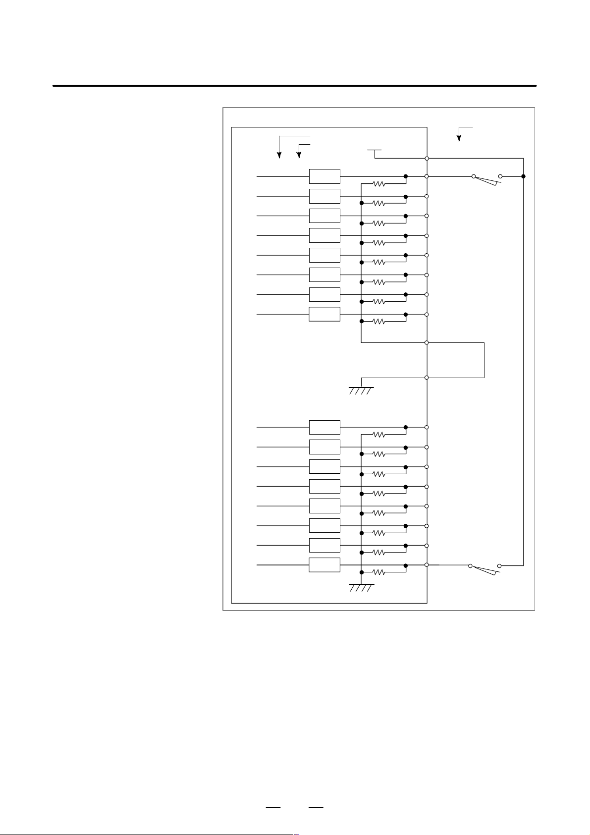
B–63503EN/01
8. CONNECTING MACHINE INTERFACE I/O
X1004.0
X1004.1
X1004.2
X1004.3
X1004.4
X1004.5
X1004.6
X1004.7
Address No.
Bit No.
RV
RV
RV
RV
RV
RV
RV
RV
+24V
COM4
T erminal No.
CB106(B01)
CB106(A02)
CB106(B02)
CB106(A03)
CB106(B03)
CB106(A04)
CB106(B04)
CB106(A05)
CB106(B05)
CB106(A14)
CB106(A01)
X1005.0
X1005.1
X1005.2
X1005.3
X1005.4
X1005.5
X1005.6
X1005.7
RV
RV
RV
RV
RV
RV
RV
RV
CB106(A06)
CB106(B06)
CB106(A07)
CB106(B07)
CB106(A08)
CB106(B08)
CB106(A09)
CB106(B09)
For address X1004, either a source or sink type (with a 0– or 24–V
common voltage) can be selected. COM4 must be connected to either 24
or 0 V; never leave it open. From the viewpoint of safety standards, it is
recommended that a sink type signal be used. The above diagram shows
an example in which the signal is of sink type (with a 24–V common
voltage).
85
Page 96

8. CONNECTING MACHINE INTERFACE I/O
B–63503EN/01
X1006.0
X1006.1
X1006.2
X1006.3
X1006.4
X1006.5
X1006.6
X1006.7
X1007.0
X1007.1
X1007.2
X1007.3
X1007.4
X1007.5
X1007.6
X1007.7
Address No.
Bit No.
RV
RV
RV
RV
RV
RV
RV
RV
RV
RV
RV
RV
RV
RV
RV
RV
T erminal No.
+24V
CB106(B01),CB107(B01)
CB106(A10)
CB106(B10)
CB106(A11)
CB106(B11)
CB106(A12)
CB106(B12)
CB106(A13)
CB106(B13)
CB107(A02)
CB107(B02)
CB107(A03)
CB107(B03)
CB107(A04)
CB107(B04)
CB107(A05)
CB107(B05)
86
Page 97

B–63503EN/01
8. CONNECTING MACHINE INTERFACE I/O
X1008.0
X1008.1
X1008.2
X1008.3
X1008.4
X1008.5
X1008.6
X1008.7
X1009.0
X1009.1
X1009.2
X1009.3
X1009.4
X1009.5
X1009.6
X1009.7
Address No.
Bit No.
RV
RV
RV
RV
RV
RV
RV
RV
RV
RV
RV
RV
RV
RV
RV
RV
T erminal No.
+24V
CB105(B01)
CB105(A06)
CB105(B06)
CB105(A07)
CB105(B07)
CB105(A08)
CB105(B08)
CB105(A09)
CB105(B09)
CB105(A10)
CB105(B10)
CB105(A11)
CB105(B11)
CB105(A12)
CB105(B12)
CB105(A13)
CB105(B13)
87
Page 98

8. CONNECTING MACHINE INTERFACE I/O
B–63503EN/01
X1010.0
X1010.1
X1010.2
X1010.3
X1010.4
X1010.5
X1010.6
X1010.7
X1011.0
X1011.1
X1011.2
X1011.3
X1011.4
X1011.5
X1011.6
X1011.7
Address No.
Bit No.
RV
RV
RV
RV
RV
RV
RV
RV
RV
RV
RV
RV
RV
RV
RV
RV
T erminal No.
+24V
CB107(B01)
CB107(A06)
CB107(B06)
CB107(A07)
CB107(B07)
CB107(A08)
CB107(B08)
CB107(A09)
CB107(B09)
CB107(A10)
CB107(B10)
CB107(A11)
CB107(B11)
CB107(A12)
CB107(B12)
CB107(A13)
CB107(B13)
88
Page 99

B–63503EN/01
For example, connecting
DO
Address No.
Bit No.
8. CONNECTING MACHINE INTERFACE I/O
T erminal No.
CB104(A24,B24,A25,B25)
CB105(A24,B24,A25,B25)
CB106(A24,B24,A25,B25)
DOCOM
CB107(A24,B24,A25,B25)
0V+24V
+24V stabilized
power supply
Y1000.0
Y1000.1
Y1000.2
Y1000.3
Y1000.4
Y1000.5
Y1000.6
Y1000.7
Y1001.0
Y1001.1
Y1001.2
Y1001.3
Y1001.4
Y1001.5
Y1001.6
Y1001.7
DV
DV
DV
DV
DV
DV
DV
DV
DV
DV
DV
DV
DV
DV
DV
DV
CB104(A16)
Relay
CB104(B16)
CB104(A17)
CB104(B17)
CB104(A18)
CB104(B18)
CB104(A19)
CB104(B19)
CB104(A20)
CB104(B20)
CB104(A21)
CB104(B21)
CB104(A22)
CB104(B22)
CB104(A23)
CB104(B23)
CB104(A01)
89
Page 100

8. CONNECTING MACHINE INTERFACE I/O
Address No.
Bit No.
B–63503EN/01
T erminal No.
CB104(A24,B24,A25,B25)
CB105(A24,B24,A25,B25)
CB106(A24,B24,A25,B25)
CB107(A24,B24,A25,B25)
0V+24V
+24V stabilized
power supply
Y1002.0
Y1002.1
Y1002.2
Y1002.3
Y1002.4
Y1002.5
Y1002.6
Y1002.7
Y1003.0
Y1003.1
Y1003.2
Y1003.3
Y1003.4
Y1003.5
Y1003.6
Y1003.7
DV
DV
DV
DV
DV
DV
DV
DV
DV
DV
DV
DV
DV
DV
DV
DV
CB105(A16)
Relay
CB105(B16)
CB105(A17)
CB105(B17)
CB105(A18)
CB105(B18)
CB105(A19)
CB105(B19)
CB105(A20)
CB105(B20)
CB105(A21)
CB105(B21)
CB105(A22)
CB105(B22)
CB105(A23)
CB105(B23)
CB105(A01)
90
 Loading...