


P-01
SACD/CD Drive Unit
Owner’s Manual
CAUTION: TO REDUCE THE RISK OF ELECTRIC SHOCK, DO NOT REMOVE COVER (OR BACK). NO USERSERVICEABLE PARTS INSIDE. REFER SERVICING TO QUALIFIED SERVICE PERSONNEL.
The lightning flash with arrowhead symbol, within an equilateral triangle, is intended to alert the user to the presence of uninsulated “dangerous voltage” within the product’s enclosure that may be of sufficient magnitude to constitute a risk of electric shock to persons.
The exclamation point within an equilateral triangle is intended to alert the user to the presence of important operating and maintenance (servicing) instructions in the literature accompanying the appliance.
IMPORTANT SAFETY INSTRUCTIONS
1)Read these instructions.
2)Keep these instructions.
3)Heed all warnings.
4)Follow all instructions.
5)Do not use this apparatus near water.
6)Clean only with dry cloth.
7)Do not block any ventilation openings. Install in accordance with the manufacturer’s instructions.
8)Do not install near any heat sources such as radiators, heat registers, stoves, or other apparatus (including amplifiers) that produce heat.
9)Do not defeat the safety purpose of the polarized or groundingtype plug. A polarized plug has two blades with one wider than
the other. A grounding type plug has two blades and a third grounding prong. The wide blade or the third prong are provided for your safety. If the provided plug does not fit into your outlet, consult an electrician for replacement of the obsolete outlet.
10)Protect the power cord from being walked on or pinched particularly at plugs, convenience receptacles, and the point where they exit from the apparatus.
11)Only use attachments/accessories specified by the manufacturer.
12)Use only with the cart, stand, tripod,
bracket, or table specified by the manufacturer, or sold with the apparatus. When a cart is used, use caution when moving the cart/apparatus combination to avoid injury from tip-over.
13) Unplug this apparatus during lightning storms or when unused for long periods of time.
14)Refer all servicing to qualified service personnel. Servicing is required when the apparatus has been damaged in any way, such as power-supply cord or plug is damaged, liquid has been spilled or objects have fallen into the apparatus, the apparatus has been exposed to rain or moisture, does not operate normally, or has been dropped.
<Do not expose this apparatus to dripps or splashes.
<Do not place any objects filled with liquids, such as vases, on the apparatus.
<Do not install this apparatus in a confined space such as a book case or similar unit.
<The apparatus draws nominal non-operating power from the AC outlet with its POWER switch in the off position.
WARNING: TO PREVENT FIRE OR SHOCK HAZARD, DO NOT EXPOSE THIS APPLIANCE TO RAIN OR MOISTURE.
CAUTION
<DO NOT REMOVE THE EXTERNAL CASES OR CABINETS TO EXPOSE THE ELECTRONICS. NO USER SERVICEABLE PARTS ARE WITHIN!
<IF YOU ARE EXPERIENCING PROBLEMS WITH THIS PRODUCT, CONTACT TEAC FOR A SERVICE REFERRAL. DO NOT USE THE PRODUCT UNTIL IT HAS BEEN REPAIRED.
<USE OF CONTROLS OR ADJUSTMENTS OR PERFORMANCE OF PROCEDURES OTHER THAN THOSE SPECIFIED HEREIN MAY RESULT IN HAZARDOUS RADIATION EXPOSURE.
For U.S.A.
This equipment has been tested and found to comply with the limits for a Class B digital device, pursuant to Part 15 of the FCC Rules. These limits are designed to provide reasonable protection against harmful interference in a residential installation. This equipment generates, uses, and can radiate radio frequency energy and, if not installed and used in accordance with the instructions, may cause harmful interference to radio communications. However, there is no guarantee that interference will not occur in a particular installation. If this equipment does cause harmful interference to radio or television reception, which can be determined by turning the equipment off and on, the user is encouraged to try to correct the interference by one or more of the following measures:
•Reorient or relocate the equipment and/or the receiving antenna.
•Increase the separation between the equipment and receiver.
•Connect the equipment into an outlet on a circuit different from that to which the receiver is connected.
•Consult the dealer or an experienced radio/TV technician for help.
CAUTION
Changes or modifications to this equipments not expressly approved by TEAC CORPORATION for compliance will void the user’s warranty.
2
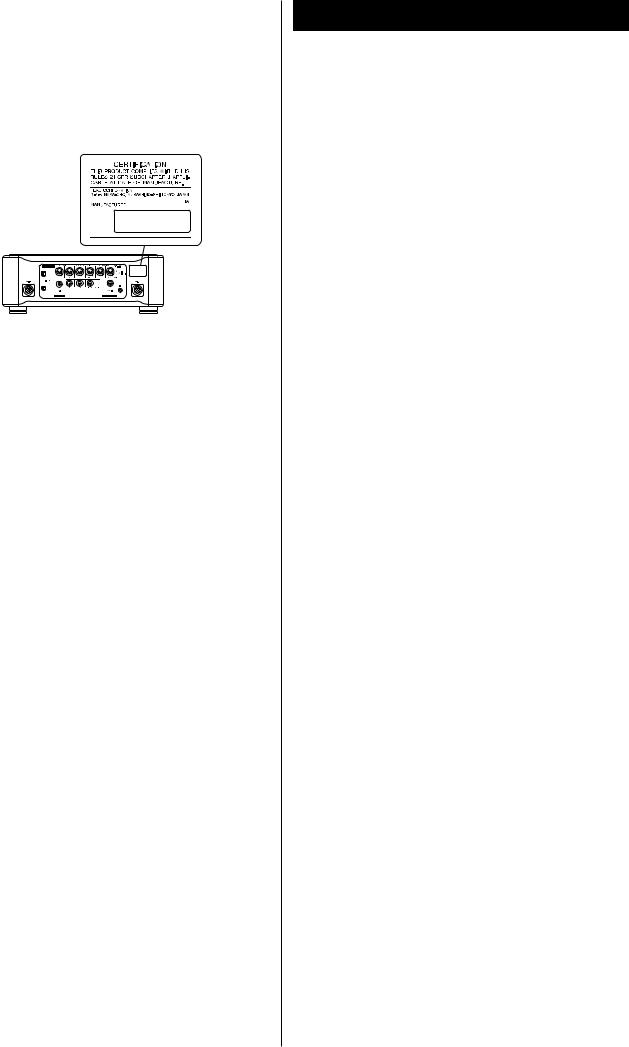
This product has been designed and manufactured according to FDA regulations “title 21, CFR, chapter 1, subchapter J, based on the Radiation Control for Health and Safety Act of 1968“, and is classified as class 1 laser product. There is not hazardous invisible laser radiation during operation because invisible laser radiation emitted inside of this product is completely confined in the protective housings.
The label required in this regulation is shown .
For U.S.A.
Optical pickup : |
|
Type |
: GH20707A2A |
Manufacturer |
: SHARP CORPORATION |
Laser output |
: Less than 1mW on the objective lens |
Wavelength |
: 788±5 nm (CD) |
|
|
VARING: APPARATEN INNEHÅLLER LASER KOMPONENT MED STRÅLNING ÖVERSTIGANDE KLASS 1.
“ADVARSEL: USYNLIG LASERSTRÅLING VED ÅBNING NAR SIKKERHEDSAFBRYDERE ER UDE AF FUNKTION. UNDGÅ UDSAETTELSE FOR STRÅLING”
“VAROITUS! SUOJAKOTELOA EI SAA AVATA. LAITE SISÄLTÄÄ LASERDIODIN. JOKA LÄHETTÄ (NÄKYMÄTÖNTÄ) SILMILLE VAARALLISTA LASERSÄTEILYÄ”.
ADVARSEL: USYNLIG LASERBESTRÅLING NÅR DENNE DELEN ER ÅPEN OG SIKKERHETSSPERREN ER UTKOBLET UNNGÅ UTSETTELSE FOR STRÅLING.
Contents
Thank you for choosing Esoteric. Read this manual carefully to get the best performance from this unit.
Features . . . . . . . . . . . . . . . . . . . . . . . . . . . . . . . . . . . . . . . . . . 4
Before Use . . . . . . . . . . . . . . . . . . . . . . . . . . . . . . . . . . . . . . . . 5
Connections . . . . . . . . . . . . . . . . . . . . . . . . . . . . . . . . . . . . . . . 6 Connection to the D-01 (XLR). . . . . . . . . . . . . . . . . . . . . . . . 8 Connection to the D-01 (IEEE1394) . . . . . . . . . . . . . . . . . . 10 Connection to the D-70 . . . . . . . . . . . . . . . . . . . . . . . . . . . 11 i.LINK (IEEE 1394) . . . . . . . . . . . . . . . . . . . . . . . . . . . . . . . . 12
Remote Control Unit. . . . . . . . . . . . . . . . . . . . . . . . . . . . . . . . 13
Names of Each Control (Main Unit) . . . . . . . . . . . . . . . . . . . . . 14
Names of Each Control (Remote Control Unit) . . . . . . . . . . . . 16
Discs . . . . . . . . . . . . . . . . . . . . . . . . . . . . . . . . . . . . . . . . . . . . 17
Basic Operation. . . . . . . . . . . . . . . . . . . . . . . . . . . . . . . . . . . . 18 Playback . . . . . . . . . . . . . . . . . . . . . . . . . . . . . . . . . . . . . . . . . 19 Skipping playback . . . . . . . . . . . . . . . . . . . . . . . . . . . . . . . . . . 20 Selecting a track . . . . . . . . . . . . . . . . . . . . . . . . . . . . . . . . . . . 20 Fast scanning . . . . . . . . . . . . . . . . . . . . . . . . . . . . . . . . . . . . . 21 Selecting the playback area. . . . . . . . . . . . . . . . . . . . . . . . . . . 21 Programmed playback . . . . . . . . . . . . . . . . . . . . . . . . . . . . . . 22 Repeat mode . . . . . . . . . . . . . . . . . . . . . . . . . . . . . . . . . . . . . 23 2 channel/Multi channel . . . . . . . . . . . . . . . . . . . . . . . . . . . . . 23 Changing the display mode . . . . . . . . . . . . . . . . . . . . . . . . . . 24 Display dimming . . . . . . . . . . . . . . . . . . . . . . . . . . . . . . . . . . . 24 Word Sync . . . . . . . . . . . . . . . . . . . . . . . . . . . . . . . . . . . . . . . 25 Up Convert . . . . . . . . . . . . . . . . . . . . . . . . . . . . . . . . . . . . . . . 25
Settings (introduction). . . . . . . . . . . . . . . . . . . . . . . . . . . . . . . 26
Audio Setup . . . . . . . . . . . . . . . . . . . . . . . . . . . . . . . . . . . . 28
Speaker Setup . . . . . . . . . . . . . . . . . . . . . . . . . . . . . . . . . . 28
Troubleshooting . . . . . . . . . . . . . . . . . . . . . . . . . . . . . . . . . . . 30
Specifications . . . . . . . . . . . . . . . . . . . . . . . . . . . . . . . . . . . . . 31
Block Diagram . . . . . . . . . . . . . . . . . . . . . . . . . . . . . . . . . . . . 32
3

Features
Newest Generation VRDS mechanism for SACD (employing a magnesium turntable and SS400 bridge)
The VRDS mechanism securely clamps the disc to the turntable, the diameter of which is exactly the same as that of the disc. This system completely eliminates vibration inherent to removable media and unwanted vibrations generated by the mechanical systems. Also, this mechanism clamps the discs at a slight inclination so as to compensate for warping or deformation improving the accuracy of the optical axes of both the laser pickup and the pit surface of the disc. This is effective in reducing the errors in reading the disc data as well as in preventing timing errors from erratic data acquisition timing.
The P-01 utilizes a magnesium turntable. Magnesium, with a specific gravity two-thirds that of aluminum, is lightweight and has excellent vibration absorption properties that help achieve high-speed rotation with extraordinary stability which are required by an SACD player. What’s more, a pair of highly precise ball bearings is used in the spindle shaft bearing unit and 20-mm thick SS400 steel is used for the support bridge that is directly joined to a 10-mm thick iron frame structure.
Coreless motor using neodymium magnets
ESOTERIC has developed a new, long-life three-phase brushless spindle motor for high-speed rotation of the large diameter turntable. In cooperation with the turntable firmly held in place with high-precision ball bearings, this motor minimizes rotation irregularities and vibrations.
Completed through scientific validations including magnetic field analysis, the optimized magnetic circuit reduces fluctuations in the motor drive current, thereby lessening any effects on audio circuits.
Pickup structure designed to prevent tilting of the laser optical axis and speed feedback-controlled sled transport
The pickup used in the P-01 has a highly rigid sliding-shaft structure that prevents the lens from tilting and the laser optical axis is kept precisely aligned with the media’s bit track. In the sled moving mechanism a proprietary Hall element sensing-type threephase brushless motor is used and powerful electronic speed feedback circuits control this sled mechanism for quick access, thereby ensuring smooth, continuous lens movement with superior response.
Highly rigid chassis to completely eliminate internal and external vibrations that might deteriorate sound quality
The chassis that supports the mechanisms includes steel bottom frame of 10-mm thickness and 4.52-kg (10 lbs) of weight. Thick aluminum is used on the top, side, bottom and front panels. The entire chassis is supported by Esoteric-exclusive pinpoint feet (patent pending) made of case-hardened tool steel.
Total attention is given to precision in mounting mechanical parts, the rigidity of the housing, and eliminating sympathetic vibration. The front and side panels constructed of thick brushed aluminum, and the rounded four corners, also of aluminum, create a feeling of dignity and gravitas, befitting of a superior SACD/CD drive unit.
Power supply section completely separated from main body
To exploit the transport potential to the full, the power supply unit is separated from the P-01 itself. The - power supply unit is equipped with three transformers: one for driving the mechanisms and motors, one for handling control signals so that the pick-up reads disc data with superior accuracy, and one for handling digital signals in the clock circuit and other areas. WB transformers, remarkable for small current loss and quick response, are used for driving the mechanism motors and for handling digital signals.
Upward conversion on CD playback
The digital audio is sent through a high-precision crystal oscillator that generates ±3ppm of accuracy (temperature characteristics included) and DSRLL III circuit to minimize jitter and do upward conversion.
The upward conversion feature makes it possible to output a maximum 192kHz signal when playing back CDs. When playing back SACD discs, the DSD signal (1 bit, 64 Fs) is sent out as acquired without upconverion or other processing.
Digital audio output
The output stage includes one multi-function XLR system (six terminals: L, R, C, SW, LS, and RS are available for ES-LINK output; two terminals: L and R for Dual AES output; and L/R terminals for XLR output), one RCA system (L/R terminals), and two IEEE 1394 systems. As an output having no upward conversion function, one RCA (NORMAL) system is provided.
No SACD data is available at the RCA jack.
Esoteric-exclusive format, ES-LINK, making SACD digital output possible
The SACD digital output is sent out of the XLR terminals in the Esoteric-exclusive ES-LINK format, or out of the IEEE 1394 interface.
When “XLR DUAL” is selected as output and an SACD disc is played , the output is automatically sent in the ES-LINK format. Only the Esoteric mono D/A converter, the D-01, is ready for ESLINK at this time.
WORD SYNC
The word sync feature allows this unit to synchronize with an external word clock. The input frequency is switch-selectable between 44.1, 88.2, 176.4, 48, 96, 192, and 100 kHz. The P-01 is designed so that the phase shift between the word clock and output sampling frequency is kept within 10 degrees when there is no discrepancy between the two. This unit can be either in “IN” mode or in “Rb IN” mode. When in Rb IN mode, a PLL circuit devoted to a highly precise clock like the rubidium controlled oscillator used in the ESOTERIC G-0s is activated.
Copper wires of 6N purity are used for primary internal wirings, Further contributing to superior sound quality
High purity 6N copper wires are used for the supplied AC power cord and most internal wiring that has effect on the sound quality thereby improving the purity and texture resolution of the sound. The insulating sheath is made of polyorefin, a non-PVC material, used out of consideration for the environment as well as sound quality. No PVC is used for any other wire insulation. The high purity 6N copper cable is developed with the help of Acro Japan Ltd. who also developed the highly acclaimed Esoteric “MEXCEL” interconnection cable and high purity 8N copper cable.
4
Before Use
What’s in the box
Please confirm that the following accessories are in the box when you open it.
Power cord x 1
DC power cable x 2
Screwdriver x 1
Remote control unit x 1
Batteries (AA, R6 or SUM-3) x 2
Felt pad x 8
Owner’s manual x 1
Warranty card x 1
Conventions about This Manual
<The types of functions and operations that can be used for a particular disc vary depending on the features built into that disc. In some cases, these functions and operations may differ from the descriptions given in this Owner’s Manual.
<The drawings about the front panel display used in this Owner’s Manual are purely for the purposes of explanation. The actual displays may differ slightly from what are shown here.
Read this before operation
<As the unit may become warm during operation, always leave sufficient space around the unit for ventilation.
<The voltage supplied to the unit should match the voltage as printed on the rear panel. If you are in any doubt regarding this matter, consult an electrician.
<Choose the installation location of your unit carefully. Avoid placing it in direct sunlight or close to a source of heat. Also avoid locations subject to vibrations and excessive dust, heat, cold or moisture.
<Do not place the unit on the amplifier/receiver.
<Do not open the cabinet as this might result in damage to the circuitry or electrical shock. If a foreign object should get into the unit, contact your dealer or service company.
<When removing the power plug from the wall outlet, always pull directly on the plug, never yank the cord.
<To keep the laser pickup clean, do not touch it, and always close the disc tray.
<Do not attempt to clean the unit with chemical solvents as this might damage the finish. Use a clean, dry cloth.
<Keep this manual in a safe place for future reference.
DO NOT MOVE THE UNIT DURING PLAYBACK
During playback, the disc rotates at high speed. Do NOT lift or move the unit during playback. Doing so may damage the disc or the unit.
WHEN MOVING THIS UNIT
When changing places of installation or packing the unit for moving, be sure to remove the disc and return the disc tray to its closed position in the player. Then, press the power switch to turn the power off, and disconnect the power cord. Moving this unit with the disc loaded may result in damage to this unit.
Placement of the unit
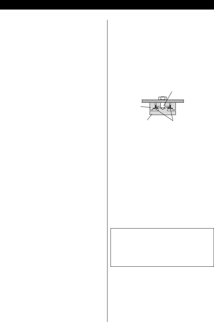
High-quality hardened tool steel is used for the pin-point feet attached to the bottom of the player. Although the outer feet may appear loose, the weight of the unit causes them to become firm and secure. The design effectively damps and reduces vibration.
<WARNING: Be careful to avoid injury when moving the unit. This unit weighs over 60 pounds! Seek assistance when moving or placing this product.
<To protect the supporting furniture surface, you may stick the felt pads supplied with the unit to the bottom of the metal feet.
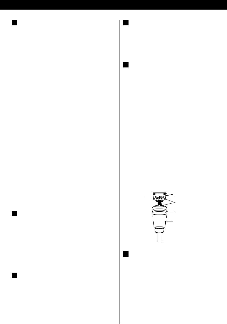
Pin-point foot
Bottom plate Frame
of the unit
Steel foot
Cover foot |
Cover foot retaining screws |
|
Beware of condensation
When the unit (or a disc) is moved from a cold to a warm place, or used after a sudden temperature change, there is a danger of condensation; vapor in the air could condense on the internal mechanism, making correct operation impossible. To prevent this, or if this occurs, leave the unit for one or two hours with the power turned on. Then the unit will stabilize at the temperature of its surroundings.
Maintenance
If the surface of the unit gets dirty, wipe with a soft cloth or use diluted neutral cleaning liquid. Be sure to remove any fluid completely. Do not use thinner, benzine or alcohol as they may damage the surface of the unit.
CAUTION
The product should not be exposed to dripping or splashing and that no object filled with liquids, such as vases, shall be placed on the product.
Do not install this equipment in a confined space such as a book case or similar unit.
5
Connections
CAUTION:
<Switch off the power to all equipment before making connections.
<Read the instructions of each component you intend to use with this unit.
<Be sure to insert each plug securely. To prevent hum and noise, avoid bundling the signal interconnection cables together with the AC power cord or speaker cables.
XLR pin assignment
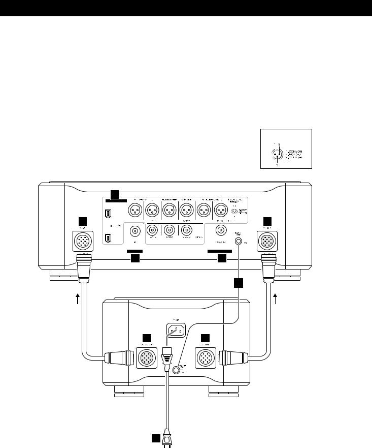
Main Unit
Direction of the arrow printed on the DC power cable
E
A
E
C |
B |
D
Power Supply Unit
Direction of the arrow printed on the DC power cable
E |
E |
F |
cord power Supplied |
6
A Digital audio output terminals
Digital audio is output from these terminals.
Connect these terminals to the digital input terminals of D/A converters (D-01) using commercially available cables.
XLR: Use balanced XLR digital audio cable COAXIAL: Use RCA (pin) digital audio cable IEEE1394 / i.LINK (AUDIO):
Use S400 compatible IEEE1394 6pin cable
To output digital surround sound from SACD discs, the ES-LINK compatible D/A converter, or an IEEE1394 (i.LINK S400 (AUDIO)) compatible D/A converter is necessary.
See pages 8-11 for details on the connection to the Esoteric D-01 or TEAC D-70.
If your D/A converter doesn’t have an IEEE1394 terminal nor ES-LINK terminal, connect P-01’s FL/FR terminal (XLR or RCA) to the digital input terminal of the D/A converter. In this case, the P-01 cannot output digital sound from SACD.
<The IEEE 1394 terminal is an interface capable of bidirectional data transmission with a connected device. You don’t need to be concerned with distinguishing between input and output.
<No digital output is available at the RCA C/SW and LS/RS terminals at this time. If no ES-LINK-capable device is connected, no digital output is available at the XLR C/SW and LS/RS terminals, either. When updated in the future, this unit will have the capability of outputting multi-channel digital audio coming from DVD-Audio sources.
B Digital audio output terminals (NORMAL)
Conventional digital audio from CD is output from this terminal. Connect this terminal to the digital input terminal of a digital device using a commercially available RCA digital audio cable.
<When you are using this terminal, select ON in the “D-OUT Norm” setting (see page 28).
<This terminal cannot output digital sound from SACD discs.
<This terminal cannot output up-converted signals.
C Word sync input terminal
This allows the use of an externally generated word clock connection, using a commercially available BNC coaxial cable (75Ω).
Devices producing such a suitable clock signal include external D-A converters, or dedicated word clock generators. Connect the WORD SYNC OUT of such a device to the unit.
D SIGNAL GND connection
Use a commercially available PVC-covered cord to connect the signal ground terminal on the unit to the amplifier signal ground.
< Note that this is NOT an electrical safety ground (earth).
E DC IN/OUT connector
Connect the DC OUT connectors of the power supply unit to the DC IN connectors of the main unit using the supplied DC power cables.
DC OUT 1 q DC IN 1
DC OUT 2 q DC IN 2
<The DC power cables carry arrow marks on them. Connect them so that the arrows point as shown on the opposite page. Making sure of the position of the cut-out in the end of the plug and the direction of the arrow on the DC power cable, hold the body of the plug, align the cut-out with the guide mark on the connector and inset the plug until it clicks in and locks in place. When unplugging the cable, firmly grasp the barrel or locking ring around the end of the plug and pull directly toward you. Do not push or pull the plug at an angle when plugging or unplugging the cable.
<Always switch off the power before plugging or unplugging the DC power cable.
<Be careful not to get your fingers pinched between the end of the plug and the connector.
Connector
Align using this mark.
Grasp the ring and pull toward you to unplug the cable.
Plug
F Power cord receptacle
After all other connections have been made, insert the supplied AC power cord into this receptacle, then connect the other end of the power cord into the AC power source. Ensure that your AC voltage corresponds to the voltage marked on the rear panel of the unit. Consult a qualified electrician if you are in doubt.
<In order to avoid the risk of electric shock, fire, or other hazard, only use the supplied power cord or a suitably approved OEM power cord.
<If you are not going to use the unit for some time, disconnect the power cord from the wall socket.
7

Connection to the D-01 (XLR)
Connection to the G-0/G-0s and two D-01 converters
P-01
Amplifier
AUDIO IN (FRONT L)
Amplifier
AUDIO IN (FRONT R)
cable digital XLR |
D-01 (FRONT L) |
XLR cable
D-01 (FRONT R) |
XLR cable |
BNC |
|
cable coaxial |
G-0/G-0s
When connecting the clock generator G-0 or G-0s, connect the WORD CLOCK OUT of the G-0/G-0s to the WORD SYNC IN of the P-01 and D-01.
8
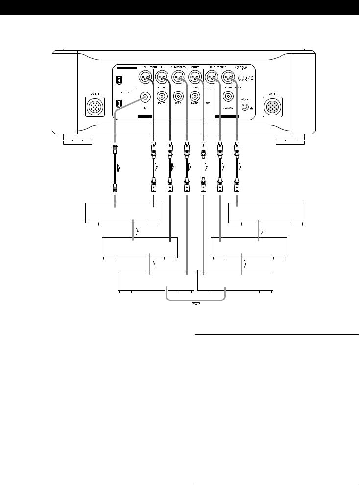
Connection to 6 sets of D-01
cable coaxial BNC |
|
cable digital XLR |
|
|
|
|
|
WORD |
WORD |
XLR 1 |
|
|
|
XLR 1 |
WORD |
SYNC |
SYNC |
|
|
|
|
|
SYNC |
OUT |
IN |
|
|
|
|
|
OUT |
D-01(R) |
|
|
|
|
|
|
D-01(SURROUND L) |
|
WORD |
WORD |
XLR 1 |
|
XLR 1 |
WORD |
WORD |
|
SYNC |
SYNC |
|
|
|
SYNC |
SYNC |
|
OUT |
IN |
|
|
|
OUT |
IN |
D-01(L) |
|
|
|
|
|
|
D-01(SURROUND R) |
|
|
WORD |
WORD |
XLR 1 XLR 1 |
WORD |
WORD |
|
|
|
SYNC |
SYNC |
|
SYNC |
SYNC |
|
|
|
OUT |
IN |
|
OUT |
IN |
|
D-01(SUBWOOFER) |
|
|
|
|
D-01(CENTER) |
||
When connecting to two D-01 units, connect the XLR terminals (FRONT L and FRONT R) of the P-01 to the XLR terminal (1 or 2) of each D-01.
When you are using six D-01 units for multi-channel listening, connect their XLR outputs in a similar way.
If the clock generator G-0/G-0s isn’t available, connect the word sync terminals as shown above (in random order).
When connecting the G-0 or G-0s with a P-01 and six D-01 units, connect the WORD CLOCK OUT of the G-0/G-0s to the WORD SYNC IN of each D-01 and connect the UNIVERSAL CLOCK OUT of the G-0/G-0s to the WORD SYNC IN of the P-01.
Setting of the P-01
OUTPUT button |
“XLR DUAL” |
WORD button |
“IN” (When the G-0s is connected, “Rb IN”) |
UP CONVERT button “176.4/192” |
|
|
|
Setting of the D-01 |
|
INPUT button |
“XLR 1” or “XLR 2” |
WORD button |
One of the D-01 that outputs word |
|
synchronization signals: “OUT” |
|
The others: “IN” |
|
When the G-0 is connected, set all the |
|
D-01s to “IN”. |
|
When the G-0s is connected, set all the |
|
D-01s to “Rb IN”. |
W_OUT setting |
“176.4” |
CH_SEL setting |
respective channels |
|
|
Setting of the G-0/G-0s
Frequency change button (A, B or C) |
176.4kHz |
FREQUENCY MODE button |
44.1kHz |
9
Connection to the D-01 (IEEE1394)
|
|
|
|
|
cable coaxial BNC |
|
|
|
|
|
|
|
|
|
|
|
|
|
|
|
|
|
|
|
|
||
|
|
|
|
|
|
|
|
|
|
|
|
||
|
|
|
|
|
|
|
|
|
|
|
|
||
|
|
|
|
|
|
|
|
|
|
|
|
||
|
|
|
|
|
|
|
|
|
|
|
|
||
|
|
|
|
|
|
|
|
|
|
|
|
||
|
|
|
|
|
|
|
|
|
|
|
|
||
|
|
|
|
|
|
|
|
|
|
|
|
||
|
cable 1394 IEEE |
|
|
|
|
|
|
|
|||||
|
|
|
|
|
|
|
|
||||||
|
|
|
|
|
|
|
|
||||||
|
|
|
|
|
|
|
|||||||
|
|
|
|
|
|
|
|
|
|
|
|
||
|
|
|
|
|
|
|
|
|
|
|
|
||
|
|
|
|
|
|
|
|
|
|
|
|
|
|
|
|
|
|
|
|
|
|
|
|
|
|
|
|
|
|
|
|
|
|
|
|
|
|||||
D-01 |
IEEE 1394 |
WORD |
WORD |
||||||||||
(L) |
IEEE 1394 |
SYNC |
SYNC |
||||||||||
OUT |
|
IN |
|||||||||||
|
|
|
|
|
|
|
|
|
|
|
|
|
|
|
|
|
|
|
|
|
|
|
|||||
|
|
|
WORD |
WORD |
|||||||||
D-01 |
IEEE 1394 |
||||||||||||
|
|
|
|
SYNC |
SYNC |
||||||||
(R) |
IEEE 1394 |
||||||||||||
OUT |
|
IN |
|||||||||||
|
|
|
|
|
|
|
|
|
|
|
|
|
|
|
|
|
|
|
|
|
|
|
|
|
|
||
|
|
|
|
|
|
||||||||
|
|
|
WORD |
WORD |
|||||||||
D-01 |
IEEE 1394 |
||||||||||||
|
|
|
|
SYNC |
SYNC |
||||||||
(SUBWOOFER) |
IEEE 1394 |
||||||||||||
OUT |
|
IN |
|||||||||||
|
|
|
|
|
|
|
|
|
|
|
|
|
|
|
|
|
|
|
|
||||||||
|
|
|
WORD |
WORD |
|||||||||
D-01 |
IEEE 1394 |
||||||||||||
|
|
|
|
SYNC |
SYNC |
||||||||
(CENTER) |
IEEE 1394 |
||||||||||||
OUT |
|
IN |
|||||||||||
|
|
|
|
|
|
|
|
|
|
|
|
|
|
|
|
|
|
|
|
||||||||
|
|
|
WORD |
WORD |
|||||||||
D-01 |
IEEE 1394 |
||||||||||||
|
|
|
|
SYNC |
SYNC |
||||||||
(SURROUND L) |
IEEE 1394 |
||||||||||||
OUT |
|
IN |
|||||||||||
|
|
|
|
|
|
|
|
|
|
|
|
|
|
|
|
|
|
|
|
|
|
|
|||||
|
|
|
WORD |
|
|
|
|
|
|||||
D-01 |
IEEE 1394 |
|
|
|
|
|
|||||||
|
|
|
|
SYNC |
|
|
|
|
|
||||
(SURROUND R) |
|
|
|
|
|
|
|
|
|
||||
|
|
|
|
OUT |
|
|
|
|
|
||||
|
|
|
|
|
|
|
|
|
|
|
|
|
|
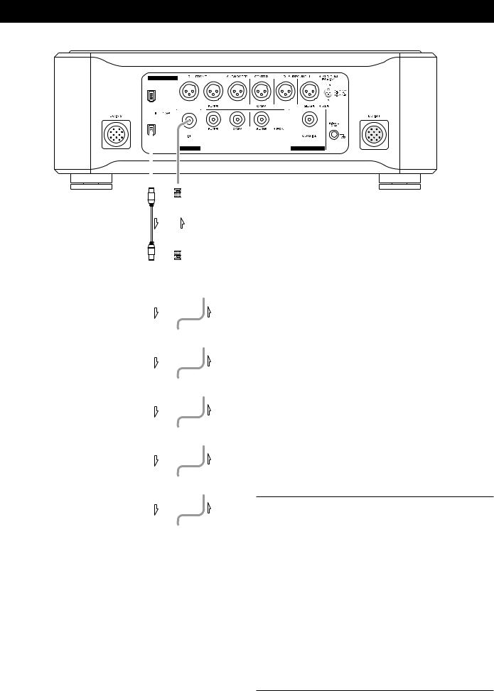
Six D-01 units are required in order to play multi-channel SACD layers on Hybrid discs without mixing them down to stereo.
When connecting two D-01 units, connect either IEEE 1394 terminal on the P-01 to the same labeled terminal on the D-01. In addition, connect the remaining IEEE 1394 terminal on the D- 01 to the same labeled terminal on the next D-01.
If you are using six D-01 units, daisy-chain all the remaining units in a similar way (in random order).
For the word sync terminals, connect them as shown (in random order).
When connecting the clock generator G-0s, connect the six WORD CLOCK OUT terminals to the WORD CLOCK IN on each unit, and connect the UNIVERSAL CLOCK OUT on the G-0s to the WORD SYNC IN on the P-01.
Setting of the P-01
OUTPUT button |
“IEEE 1394” |
WORD button |
“IN” (When the G-0s is connected, “Rb IN”) |
UP CONVERT button “176.4/192” |
|
|
|
Setting of the D-01 |
|
INPUT button |
“IEEE 1394” |
WORD button |
One of the D-01 that outputs word |
|
synchronization signals: “OUT” |
|
The others: “IN” |
|
When the G-0s is connected, set all the |
|
D-01 to “Rb IN”. |
W_OUT setting |
“176.4” |
CH_SEL setting |
respective channels |
|
|
Setting of the G-0s
Frequency change button (A, B or C) |
176.4kHz |
FREQUENCY MODE button |
44.1kHz |
10
 Loading...