

Page 1
Multiporator
Bedienungsanleitung
Operating Manual
Mode d'emploi
Istruzioni d'impiego
Manual de Instrucciones
Page 2

Page 3

Bedienungsanleitung. . . . . . . . . . . . . . . . . . . . . . . . . . . . . . . . . . . . . . . 4
Operating Manual . . . . . . . . . . . . . . . . . . . . . . . . . . . . . . . . . . . . . . . . 46
Mode d’emploi. . . . . . . . . . . . . . . . . . . . . . . . . . . . . . . . . . . . . . . . . . . 89
Istruzioni d'impiego . . . . . . . . . . . . . . . . . . . . . . . . . . . . . . . . . . . . . . 131
Manual de Instrucciones . . . . . . . . . . . . . . . . . . . . . . . . . . . . . . . . . . 172
EG-Konformitätserklärung. . . . . . . . . . . . . . . . . . . . . . . . . . . . . . . . . 213
EC Conformity Declaration
Déclaration de conformité
Dichiarazione di conformità CE
Declaración de conformidad CEE
Nachdruck und Vervielfältigung – auch auszugsweise – nur mit Genehmigung.
No part of this publication may be reproduced without the prior permission of
the copyright owner.
Toute reproduction, complète ou partielle et quel que soit le proèdè est
interdiete, sauf autorisation expresse de notre part.
Ristampa e riproduzione – anche di estratti – solo con autorizzazione.
Reimpresión y copia – incluso parciales – sólo con autorización.
Copyright
©
2006 by Eppendorf AG, Hamburg
B 4308 900.016-10/0606
3
Page 4

Contents
1 General information
2 Area of application
3 Safety precautions
4 Device description
4.1 Delivery package . . . . . . . . . . . . . . . . . . . . . . . . . . . . . . . . . . 52
4.2 Startup . . . . . . . . . . . . . . . . . . . . . . . . . . . . . . . . . . . . . . . . . . 53
4.3 Cuvette insert. . . . . . . . . . . . . . . . . . . . . . . . . . . . . . . . . . . . . 53
4.4 Keypad. . . . . . . . . . . . . . . . . . . . . . . . . . . . . . . . . . . . . . . . . . 54
4.5 Keys and key combinations . . . . . . . . . . . . . . . . . . . . . . . . . . 54
4.6 Display . . . . . . . . . . . . . . . . . . . . . . . . . . . . . . . . . . . . . . . . . . 57
4.7 Electroporation. . . . . . . . . . . . . . . . . . . . . . . . . . . . . . . . . . . . 58
4.7.1 Cuvettes and cuvette insert . . . . . . . . . . . . . . . . . . . . . . . . . 58
4.7.2 Electroporation buffer for eukaryotic cells . . . . . . . . . . . . . . . 59
4.8 Cell fusion (optional) . . . . . . . . . . . . . . . . . . . . . . . . . . . . . . . 60
4.8.1 Micro fusion chamber (Electrode gap width 0.2 mm). . . . . . . 60
4.8.2 Micro fusion chamber (Electrode gap width 0.5 mm). . . . . . . 61
4.8.3 Cleaning the Micro fusion chamber . . . . . . . . . . . . . . . . . . . . 61
4.8.4 Helix fusion chamber . . . . . . . . . . . . . . . . . . . . . . . . . . . . . . 62
4.8.5 Filling the Helix fusion chamber . . . . . . . . . . . . . . . . . . . . . . 63
4.8.6 Fusion and cell suspension extraction . . . . . . . . . . . . . . . . . . 64
4.8.7 Cleaning and disinfecting the Helix fusion chamber . . . . . . . 65
4.8.8 Electrofusion buffer for eukaryotic cells . . . . . . . . . . . . . . . . . 65
4.9 Insert (electroporation / electrofusion) for connecting
external electrodes. . . . . . . . . . . . . . . . . . . . . . . . . . . . . . . . . 66
4.10 Printer connection / printer (optional). . . . . . . . . . . . . . . . . . . 67
5 Mode of operation
5.1 Mode for electroporation of eukaryotic cells . . . . . . . . . . . . . 71
5.2 Mode for electroporation of bacteria and yeast (optional) . . . 73
5.3 Mode for cell fusion (optional) . . . . . . . . . . . . . . . . . . . . . . . . 75
5.3.1 Function: Cell alignment. . . . . . . . . . . . . . . . . . . . . . . . . . . . . 75
5.3.2 Procedure for cell fusion . . . . . . . . . . . . . . . . . . . . . . . . . . . . 77
6 Error messages
7 Maintenance and servicing
7.1 Disinfection . . . . . . . . . . . . . . . . . . . . . . . . . . . . . . . . . . . . . . 82
7.2 Cleaning. . . . . . . . . . . . . . . . . . . . . . . . . . . . . . . . . . . . . . . . . 82
8 Technical data
9 Ordering information
9a Ordering information for North America
. . . . . . . . . . . . . . . . . . . . . . . . . . . . . . . 47
. . . . . . . . . . . . . . . . . . . . . . . . . . . . . . . . 48
. . . . . . . . . . . . . . . . . . . . . . . . . . . . . . . . 49
. . . . . . . . . . . . . . . . . . . . . . . . . . . . . . . . 51
. . . . . . . . . . . . . . . . . . . . . . . . . . . . . . . . 71
. . . . . . . . . . . . . . . . . . . . . . . . . . . . . . . . . . 80
. . . . . . . . . . . . . . . . . . . . . . . . . 82
. . . . . . . . . . . . . . . . . . . . . . . . . . . . . . . . . . . 83
. . . . . . . . . . . . . . . . . . . . . . . . . . . . . . 85
. . . . . . . . . . . . . . 87
46
Page 5

1 General information
The Multiporator
With the aid of optional modules, it is also possible to perform
electroporation on bacteria and yeast as well as fusion of cells. This
manual contains information on all possible uses of the Multiporator
The outstanding feature of the Multiporator is that the parameters
entered for the electroporation of eukaryotic cells and for cell fusion are
maintained exactly by means of internal calculation of the discharge
curve.
is designed for the electroporation of eukaryotic cells.
.
47
Page 6

2 Area of application
Device safety regulations and industrial standards stipulate the following
conditions:
Use the device for experiments in the field of cell technology
–
only
The range of application covers the electroporation of yeast and
bacteria and eukaryotic cells as well as cell fusion.
–
Please use only original accessories from Eppendorf
Original accessories only may be used. They are designed
specifically to ensure optimum functioning of the Multiporator
Additional devices may be used only if recommended by the
manufacturer. Eppendorf does not honor any warranty or accept
any responsibility for damage resulting from the use of incorrect
or non-recommended equipment.
– The device may only be used for research purposes, not for
medical and diagnostic applications
.
48
Page 7

3 Safety precautions
For reasons of personal safety, it is essential to observe the following!
●
Observe the instructions contained in the operating manual
It is essential to comply with the information given in the manual!
● Only use the device with a power supply which has a grounding
contact!
● Before starting up the Multiporator
supply used corresponds to the voltage specifications on the
identification plate!
● Do not use the device if it is damaged, especially if the mains cable is
damaged.
● The unit may be opened only by authorized service personnel! Before
opening the device, switch it off and remove the power supply plug.
Potentially lethal voltage inside the unit.
● Do not operate the device in an explosive environment!
● Do not allow any liquid to enter into the Multiporator
● The device should be used for in vitro applications only!
● Use the device only for the purpose for which it is intended.
Do not place parts, devices, tools or other objects into the cuvette
insert which have not been recommended by Eppendorf AG.
High voltage!
● Use the listed accessories only.
Other accessories may only be used if they are accompanied by a
safety certificate from Eppendorf AG confirming their suitability for
use!
● Electrical connection to devices which are not mentioned in this
operating manual is only permitted with the prior consent of the
manufacturer!
● The Helix fusion chamber must be handled with care.
Loose or damaged electrodes adversely affect operating procedures.
In such cases, the Helix fusion chamber must not be used!
Do not open the Helix fusion chamber until fusion has finished!
● The Micro fusion chamber must be handled with care.
Ta ke care when filling with cell suspension. Do not touch or move the
electrodes with the pipette tip! This may cause damage.
During cell alignment/fusion, avoid direct contact with the electrodes!
, please ensure that the power
or the inserts!
49
Page 8

3 Safety precautions
● Cell alignment/fusion may be performed only when the Micro fusion
chamber is connected.
The cable is designed for connection to the Micro fusion chamber only.
No other connections are permitted! Do not place the plug into liquid!
● The owner or operator of the device is liable for the functioning of the
device when the device is serviced or maintained by persons who are
not members of the Eppendorf service personnel or when the device
is not operated in accordance with the given regulations and
precautions. Eppendorf AG accepts no liability for damage resulting
from such action. Warranty and liability stipulations which form part of
the terms of sale and delivery of Eppendorf AG are not affected by the
above-mentioned conditions.
● This operating manual or parts of this operating manual may not be
reproduced in any form without the prior written permission of
Eppendorf AG!
● Eppendorf AG reserves the right to make technical alterations to this
product!
●
Transfer
If the device is passed on to someone else, please include the
instruction manual.
●
Disposal
In case the product is to be disposed of, the relevant legal regulations
are to be observed.
●
Information on the disposal of electrical and electronic devices in
the European Community
The disposal of electrical devices is regulated within the European
Community by national regulations based on EU Directive 2002/96/EC
on waste electrical and electronic equipment (WEEE).
According to these regulations, any devices supplied after 13.08.05 in
the business-to-business sphere, to which this product is assigned,
may no longer be disposed of in municipal or domestic waste. They
are marked with the following symbol to indicate this.
As disposal regulations within the EU may vary from country to
country, please contact your supplier if necessary.
50
Page 9
4 Device description
The device has four different modification levels: the basic device is used
for the electroporation of eukaryotic cells. It can then be developed for the
electroporation of bacteria and yeast, with an additional level offering the
opportunity to perform cell fusion. These two levels can be combined to
form the fourth level.
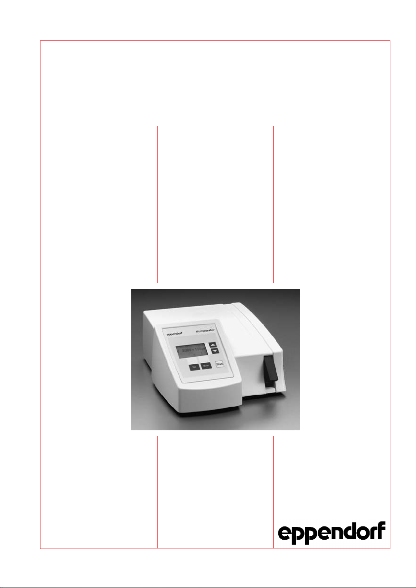
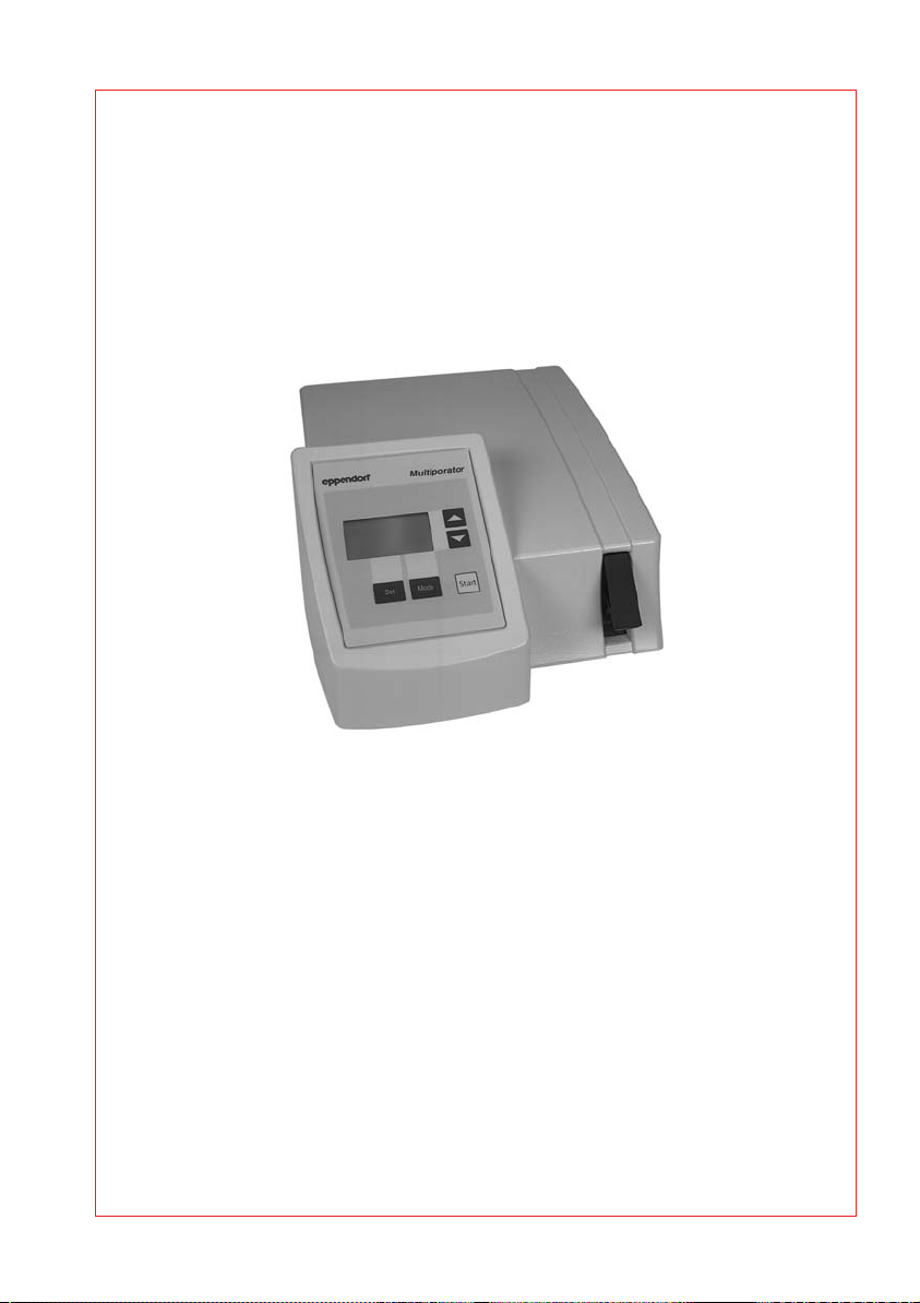
The Multiporator
The insert for the electroporation cuvette is located next to the keypad.
is operated using an easy-to-follow keypad with display.
Fig. 1: Multiporator, front view
51
Page 10

4 Device description
4.1 Delivery package
Basic device: Multiporator for the electroporation of eukaryotic
cells; with mains cable
Insert for electroporation cuvettes
Electroporation cuvettes
(Electrode gap width: 2 mm / 4 mm)
Hypo- and isoosmolar buffers for electroporation
Operating manual and Basic Applications Manual
"Bacteria module" optional:
"Cell fusion module" optional:
"Fusion- and bacteria module" optional:
Basic device incl. accessories
with integrated bacteria module
Additional electroporation cuvettes
(Electrode gap width: 1 mm)
Basic device incl. accessories
with integrated cell fusion module
Helix fusion chamber
(Electrode gap width: 0.2 mm)
Insert for Helix fusion chamber
Micro-fusion chamber
(Electrode gap width: 0.2 mm) with special insert
Hypo- and isoosmolar buffers for cell fusion
Basic device incl. accessories
with integrated fusion- and bacteria module.
52
Page 11
4 Device description
4.2 Startup
The Multiporator must stand completely on the stable work surface and be
safely positioned. There must be enough space that the front and rear
ventilation slits are not covered and that air for cooling can reach
underneath the device.
Space requirement: Width: 25.2 cm
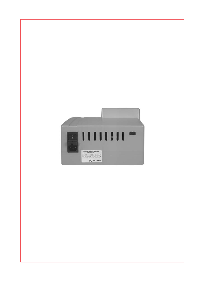
The main power socket with fuse and main power switch is located on the
rear of the Multiporator
tion on the ID plate. To start the device, insert the power cable into the
main power socket and connect it up to the main power supply. Turn on or
off the device by pressing the main power switch.
Depth: 34.2 cm
Height: 12.0 cm
. The mains power must agree with the informa-
Fig. 2: Multiporator, rear view
Power connection (left)
Printer connection (right)
The delivery carton should be kept in order to be able to safely send back
the device in case repairs are necessary.
4.3 Cuvette insert
The insert for the electroporation cuvette is next to the keypad at the
front of the device. To remove the cuvette, pull out the cuvette insert.
When inserting a new cuvette, ensure that the nose of the cuvette fits into
the rear slot. Push the cuvette insert containing the cuvette into the device
up to the stop. A sensor in the device detects whether the cuvette insert
contains a cuvette.
Note:
When transporting the device, please ensure that the insert
contains an empty cuvette. Alternatively, transport the cuvette insert
separately.
Different inserts are used for the modification level "cell fusion".
53
Page 12
4 Device description
4.4 Keypad
The keypad is used to enter the electroporation or the electrofusion
modes, to select the parameters and to start the application. Depending
on the modification level, 1 to 3 modes can be selected. Key combinations
can be used to set the date and time as well as the volume of the acoustic
signal.
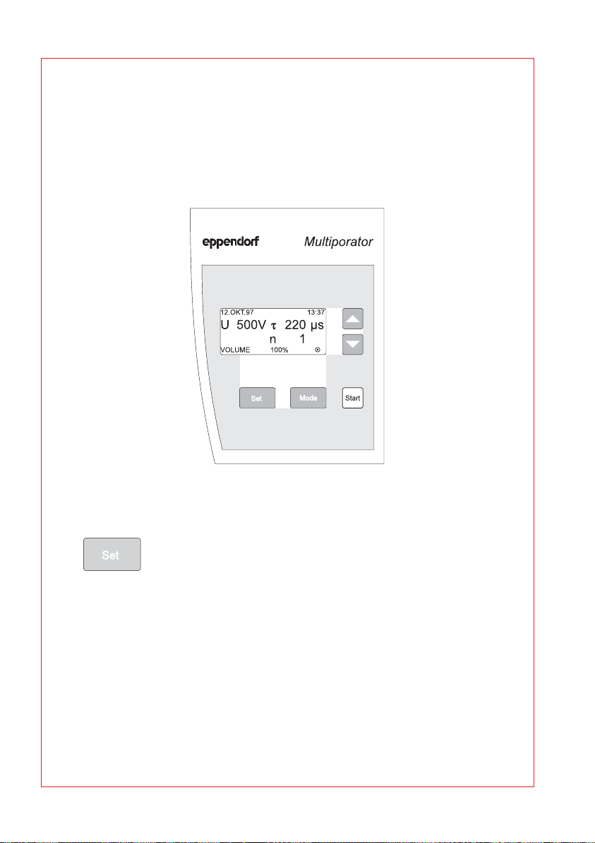
Fig. 3: Control panel with keys and display
4.5 Keys and key combinations
SET
The SET key is used to select the desired parameter. This
parameter is underlined in the display. Further parameters
are selected by pressing the SET key an appropriate
number of times. A SET sequence is ended either by
pressing the SET key repeatedly until the underlining
disappears or by pressing the MODE or START key.
(Note:
The MODE key switches to another mode if
available.) Parameters are modified using the up/down
arrow keys. When the lowest possible value has been
reached, the display then moves to the highest value.
Similarly, when the highest value has been reached, the
display then moves to the lowest value.
54
Page 13
4 Device description
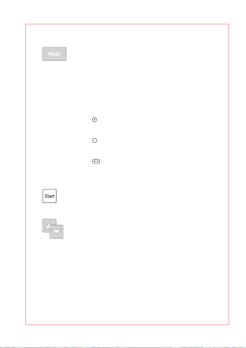
MODE
The MODE key is used to activate the mode with
which electroporation or electrofusion is to be
performed. It is only possible to select modes in
accordance with the modification level of the device.
This means for the basic device, the mode for the
electroporation of eukaryotic cells is available, while
there is a choice of three modes for the maximum
expansion level.
The corresponding symbol then appears in the
display:
: Mode for eukaryotic cells
Modification level: Basic device
Pulse used: Decaying e-function
: Mode for bacteria and yeasts
Modification level: Bacteria module
Pulse used: Decaying e-function
: Mode for cell fusion
Modification level: Fusion module
Pulse used: Square-wave pulse
START
The process required is started by pressing the
START key.
Arrow keys
The arrow keys are used to modify the selected
(i.e. underlined) parameters in the desired direction.
55
Page 14
4 Device description
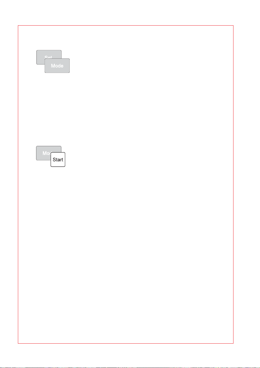
Setting the date
The procedure for setting the date and time can
be activated by pressing the SET and MODE keys
simultaneously. If the SET key is pressed again,
the underlining in the display for the date and time
moves from left to right. The arrow keys can thus
be used to modify the settings.
To end the process for setting the date, press the
SET key repeatedly until the underlining is no longer
visible in the display. Alternatively, the underlining
disappears from the display when the MODE or
START key is pressed.
switches to another mode if available.)
Setting the volume of the acoustic signals
The procedure for setting the volume of the acoustic
signals can be activated by pressing the MODE
and START keys simultaneously. "VOLUME" then
appears in the bottom line of the display, together
with a figure in percent. This figure indicates the
volume and the tone type and can be modified using
the arrow keys.
To end the procedure for setting the volume of the
acoustic signals, press the SET, MODE or START
key.
(Note:
mode if available.) "VOLUME" then disappears from
the display.
(Note:
The MODE key
The MODE key switches to another
56
Reset
An experiment can be terminated only by pressing
the main power switch. This switch also functions as
a reset switch.
Page 15
4 Device description
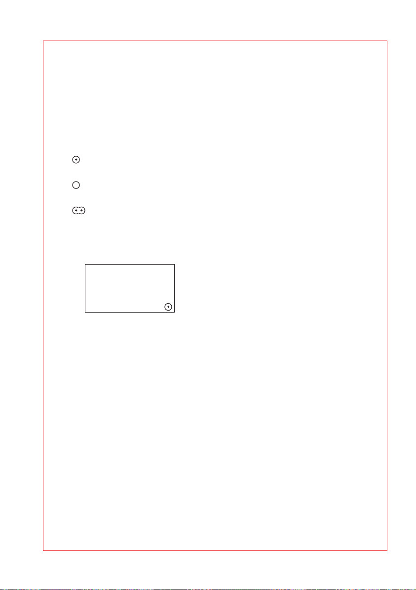
4.6 Display
The date and time of day are always displayed in the uppermost line of
the display. The parameters which are relevant for the experiment appear
in lines 2 to 4 in larger letters and in bold print. The parameters and the
number of parameters differ according to the mode which has been
selected. The mode which has been selected is always represented by a
symbol on the right of the bottom line:
: Mode for eukaryotic cells
Modification level: Basic device
: Mode for bacteria and yeasts
Modification level: Bacteria module
: Mode for cell fusion
Modification level: Fusion module
"VOLUME" or the remaining time for the experiment can also appear in
the display in this line.
n
13:37
220µs
1
Example of the display for setting
the volume of the acoustic signal
12.AUG.00
U 500V
VOLUME 100%
τ
During and after the experiment, the display changes to show the
information relevant to the stage of the experiment which has been
reached.
57
Page 16

4 Device description
4.7 Electroporation
4.7.1 Cuvettes and cuvette insert
The electroporation of eukaryotic cells, bacteria or yeasts is carried out in
disposable cuvettes. The biological material is placed in the gap between
the electrodes of the cuvette, whereby the prescribed liquid volumes of
the relevant cuvette are to be maintained. Although a supernatant above
the electrode does not drastically affect the experiment, however it
reduces the general efficiency.
A matt window allows the cuvette to be inscribed.
The plastic nose on the cuvette ensures that the cuvette is inserted
correctly into the cuvette insert. The lid seals the cuvette. However, to
safeguard against excess pressure, the cuvette is not hermetically sealed
by the lid. A filled cuvette should therefore be transported in an upright
position only in order to ensure that biological material does not leak out.
Lid
Plastic cuvette
Plastic nose
Electrodes
Gap
Fig. 4: Schematic diagram of electroporation cuvette
The cuvette insert is removed from the Multiporator
using the protruding
grip. No bubbles are present when the cuvette is filled.
When the cuvette is inserted into the inner recess of the cuvette insert,
care must be taken to ensure that the cuvette nose is positioned in the
long slit and that the cuvette is in contact with the base of the cuvette
insert. The cuvette insert, complete with cuvette, is then pushed into the
device up to the stop.
The cuvette insert may be stored in a cool place.
When transporting the device, please note that the cuvette insert may slip
out of the device if no cuvette has been inserted (see chap. 4.3).
58
Page 17

4 Device description
4.7.2 Electroporation buffer for eukaryotic cells
To achieve optimal transfection results, the original electroporation buffer
from Eppendorf, with a low electrical conductivity, should be used. These
electroporation buffers (hypo and isoosmolar) are tested for sterility and
the absence of mycoplasms and endotoxins.
The use of these buffer systems means that considerably less current
flows during electroporation, with the result that no significant damage is
sustained by the cells. Simultaneously, the use of appropriate buffer
media results in the electrically induced "pores" being much larger than
those of pulse applications in conductive solutions.
Ideally, the electroporation should be carried out in hypoosmolar buffer.
Through the hypoosmolar buffer system, the cells absorb water shortly
before the pulse and swell as a result. Due to a variety of effects, including
the lowering of the breakdown voltage, this process enables increased
permeability of the plasma membrane. The yields can thereby be
considerably increased in comparison to those under isoosmolar
conditions. In the case of cells that react sensitively to purely hypoosmolar
conditions, step-by-step addition of the isoosmolar electroporation buffer
can be used to adjust the necessary osmolarity.
The Eppendorf electroporation buffer should be used for the electroporation of eukaryotic cells (with the exception of yeasts and some
microorganisms and plants). Electroporation media with low conductivity
can be used for the electroporation of bacteria, yeasts and other
microorganisms. Detailed application protocols can be downloaded from
the Eppendorf Homepage www.eppendorf.com.
59
Page 18

4 Device description
4.8 Cell fusion (optional)
4.8.1 Micro fusion chamber (Electrode gap width 0.2 mm)
With the help of the Micro fusion chamber, the parameters for the cell
alignment and for the cell fusion can be optimized under microscopic
control.
The Micro fusion chamber consists of a housing equipped with a
transparent reservoir, into which two electrodes with a gap of 200 µm are
embedded. The connection to the Multiporator takes place through a
coaxial cable (approx. 1 m) over a special insert (see Fig. 5).
12 4
Insert of Micro fusion chamber
1 Contacts
Fig. 5: Schematic diagram of the insert and the Micro fusion chamber
Caution :
2 Earthing springs
The Micro fusion chamber must be handled with care.
3 Cable
3
Micro fusion chamber
4 Coaxial connector
3
Ta ke care when filling with cell suspension. Do not touch or move the
electrodes with the pipette tip. This may cause damage!
During cell alignment/fusion, avoid direct contact with the
electrodes. Cell alignment/fusion may be performed only when
the micro fusion chamber is connected.
– Slide the Micro fusion chamber firmly into the Multiporator
.
– Place the Micro fusion chamber (which is filled with approx. 20–50 µl
cell suspension) onto the microscope.
Note :
Pipetting the cell suspension carefully onto the area around the
electrodes can maximize the number of cells between the electrodes.
– The brackets can be used
to lock into place on the
microscope table. They
can also be used to
fasten a glass slide.
60
Page 19

4 Device description
– Connect the Micro fusion chamber with the coaxial connection of the
cable.
–Focus the electrodes and cells under the microscope.
– Run through the parameters by pressing the START key. This can be
monitored under the microscope (see chap. 5.3).
200 µm
Alignment of the cells
between the electrodes
Fig. 6: Microscopic view of the cells during the alignment and after the fusion
sequence with individual fusion products
The parameters determined to be optimal can be directly adopted for the
fusion in the Helix fusion chamber (see chap. 4.8.4).
Cells after fusion and fusion products
4.8.2 Micro fusion chamber (Electrode gap width 0.5 mm)
The non-standard accessories (see "Ordering information") contain a
Micro fusion chamber with a modified electrode interval of 500 µm. With
the help of this Micro fusion chamber, cells can be fused under
microscopic control.
General instructions for usage of a Micro fusion chamber are given in
chapter 4.8.1 and in the Basic Applications Manual for electrofusion. This
is included in the delivery package of the fusion module.
Important note:
Applications Manual for electrofusion), the modified electrode interval of
500 µm must be taken into account. Please note that the parameters
determined as optimal cannot be adopted directly for fusion in the Helix
fusion chamber.
When calculating the fusion parameters (see Basic
4.8.3 Cleaning the Micro fusion chamber
The content of the Micro fusion chamber is rinsed out using bi-distilled
water from a spray bottle. Cell residue that is particularly stubborn can be
removed by carefully cleaning the electrodes with a soft toothbrush using
vertical strokes. (The space between the electrodes must not be changed
during this process!) The drying process can be accelerated by rinsing the
chamber with 70 % non-denatured ethanol.
61
Page 20

4 Device description
4.8.4 Helix fusion chamber
The Helix fusion chamber has been specially designed for the production
of larger quantities of fusion products (hybrids). It consists of a conical
tapered core that carries the electrodes and a beaker into which the cell
suspension is added (see fig. 7).
Fig. 7: Helix fusion chamber
Diagram of Helix fusion chamber
The Helix fusion chamber (see fig. 8) consists of a cup (1) and a core with
parallel wound platinum wires, which are the electrodes (2). They are
wound around the core as a double helix. Both parts are screwed
together. The gap (4) between the cup and the core has a filling volume of
250 µl.
The Helix fusion chamber is linked to the insert (6) for cell fusion via the
coaxial connector (3).
3
1
4
2
5
Cup Core Helix fusion chamber Fusion insert
1 Thread 2 Electrodes
Fig. 8: Schematic representation of the Helix fusion chamber and the fusion insert
3 Coaxial
connector
4 Gap for cell fusion 5 Contacts
6 Coaxial connector
62
6
Page 21

4 Device description
The gap between the wound platinum electrodes is approx. 200 µm.
200 µm
Fig. 9: Microscope view of the electrodes of the Helix fusion chamber
Caution :
Loose or damaged electrodes adversely affect operating procedures.
In such cases, the Helix fusion chamber must not be used!
4.8.5 Filling the Helix fusion chamber
The Helix fusion chamber is filled with 250 µl cell suspension. It is
essential to ensure that the liquid is pipetted into the deepest possible
position in the cup. The edge and the walls must not be wetted as this has
an adverse effect on filling the Helix fusion chamber. Air bubbles may form
which reduce the effectivity of the experiment.
The core is inserted into the upright cup in the stand and carefully
screwed into place. As a result of this screwing action, the cell suspension
in the ever-decreasing gap is forced upwards.
Handle the Helix fusion chamber with care!
63
Page 22

4 Device description
When screwing the core, make sure that no air bubbles form.
Fig. 10: Filling the Helix fusion chamber (schematic representation)
Leave the closed Helix fusion chamber upside-down on the coaxial
connector until the fusion process has been completed!
4.8.6 Fusion and cell suspension extraction
– Slide the fusion insert firmly into the device.
– Place the closed Helix fusion chamber onto the coaxial connector
and lock it into place by rotating it a quarter-turn.
– Carry out the fusion with the set parameters (see chap. 5.3).
– Loosen the Helix fusion chamber carefully by rotating it a quarter-turn
and then remove it.
–To open the chamber, place it in a vertical position (e.g. in the stand).
– Unscrew the core carefully from the beaker.
– Using a small quantity of the appropriate medium, rinse off any cell
suspension that may be on the core.
– The cell suspension from the beaker is mixed with the cell suspension
that has been rinsed off and is then treated further as required.
64
Page 23

4 Device description
4.8.7 Cleaning and disinfecting the Helix fusion chamber
The beaker and core of the Helix fusion chamber should be rinsed with
distilled water directly after the experiment in order to prevent cell and
buffer residue from drying up.
If heavily contaminated, the Helix fusion chamber should be cleaned
briefly in an ultrasonic bath (possibly with a cleaning supplement, such as
Edisonite Super) or with a very soft (tooth)brush. When cleaning is carried
out using brushes, please ensure that brushing is carried out in the same
direction as the windings, since the electrodes may otherwise move out of
their correct position and thus render the Helix fusion chamber unusable.
Disinfect the parts using non-denatured 70 % ethanol. To do this, the
beaker is filled with 250 µl of ethanol and the core screwed into the
beaker. After
removed. To subsequently dry the beaker and the core place them in the
stand under sterile, dust-free conditions. After drying, the Helix fusion
chamber may be re-used.
4.8.8 Electrofusion buffer for eukaryotic cells
The electrofusion medium (fusion buffer) is of considerable importance for
the survival rate of the cells and for the successful extraction of hybrid
cells. Only a single buffer should be used for the entire electrofusion
procedure (alignment, fusion, post-alignment) in order to protect the cells
from additional stress. The fusion buffers from Eppendorf are
differentiated from the commonly used fusion media by low conductivity
and low osmolarity. The low conductivity (120 µS/cm) of the Eppendorf
buffers enables the application of relatively low field strengths (voltage)
when merging cells.
Ideally, electrofusion should be carried out in hypoosmolar buffer. As a
result of the hypoosmolar buffer system, the cells absorb water shortly
before the pulse and swell. The membrane and actin skeleton proteins are
thereby temporarily disengaged, thus easing fusion in the electrical field.
The yields of fusion products attained can thereby be considerably
increased in comparison to those under isoosmolar conditions. For cells
that react sensitively under purely hypoosmolar conditions, the necessary
osmolarity can be adjusted through step-by-step addition of the
isoosmolar buffer.
The Eppendorf fusion buffers (hypo and isoosmolar) are tested for sterility
and the absence of mycoplasma and endotoxins.
10 seconds
, the core is unscrewed and the alcohol can be
65
Page 24

4 Device description
4.9 Insert (electroporation / electrofusion)
for connecting external electrodes
Prior to using the insert for the connection of external
electrodes, the supplement sheet accompanying the insert
must be read thoroughly. The safety instructions found in the
supplement sheet must be observed.
The non-standard accessories (see "Ordering information") contain an
insert, to which it is possible to connect external electrodes. By changing
the position of a function switch ( P / F ) accordingly, the insert can be used
for electroporation (symbols ) or for cell fusion with external
electrodes (symbol ).
The electrodes are connected using two 4 mm contact-proof
laboratory plugs.
1
2
Position of the function switch for electroporation P
1
2
Position of the function switch for electrofusion F
1
Connecting socket, positive pole (red)
2
Connecting socket, ground (black)
Fig. 11: Insert for the connection of external electrodes (schematic representation)
Attention! Characteristic of electrofusion of cells with
external electrodes:
During the electrofusion, a resistance of 50 Ohm must be
connected parallel to the electrodes with the help of plug in
connections.
66
Page 25

4 Device description
When external electrodes are connected, the relevant national
safety regulations (relating to high voltage) and EMC
regulations apply and should be observed
(EMC: electro-magnetic compatibility).
The user is responsible for all equipment that has been
connected!
4.10 Printer connection / printer (optional)
The Multiporator
This protocol contains the parameters used as well as the date and time,
which are automatically retained. Additional data pertaining to the
experiment, such as buffer, concentration or cell line, can also be entered
by hand. In the event of an error occurring, the error message is also
printed out. Examples of printouts for different applications are shown
below:
18.Aug.00 16:03:04 eppendorf Multiporator 4308 V4.00
Higher Eucaryotic Cells U = 100 V,
Cuvette Gap Width 1mm 2mm 4mm
Strain / Cell Line ______________________________
Cell Density ______________________________
Tr ansfer Substance ______________________________
Concentration ______________________________
Buffer ______________________________
Temperature ______________________________
can supply a printer protocol for each experiment.
τ
= 50 µs, n = 1
67
Page 26

4 Device description
18.Aug.00 16:42:47 eppendorf Multiporator 4308 V4.00
Bacteria and Yeast U = 1000 V, Ua = 992 V,
Cuvette Gap Width 1mm 2mm 4mm
Strain / Cell Line ______________________________
Cell Density ______________________________
Tr ansfer Substance ______________________________
Concentration ______________________________
Buffer ______________________________
Temperature ______________________________
18.Aug.00 16:17:49 eppendorf Multiporator 4308 V4.00
Cell Fusion U'
Fusion Chamber
Strain / Cell Line A ______________________________
= 8.0 V, t = 20 s
~
U
= 15 V, t = 100 µs, n = 3
U"
= 4.0 V, t = 10 s
τa = 5.0 ms
68
Cell Density A ______________________________
~
Strain / Cell Line B ______________________________
Cell Density B ______________________________
Buffer ______________________________
Temperature ______________________________
Page 27

4 Device description
18.Aug.97 15:59:08 eppendorf Multiporator 4308 V1.00
******** ERROR 07 ********
******** Short τ *********
Serial printers can be connected to the serial printer interface at the rear
of the device. It is also possible to read protocols for documentation
purposes via a PC terminal program. This requires a zero-modem cable
(9-pin socket / 9-pin socket, order no. 0013 610.525).
The following thermal printers are available from Eppendorf AG. The DIP
switch setting for an IBM-compatible printer is also described:
Order no.
Printer type
Accessories
Connecting
cable
Thermal printer DPU-414 0013 608.148
Power unit (230 V)
Power unit (115 V)
Thermal paper (10 rolls)
9-pin socket / 9-pin plug
cable guide 1:1
(for Thermal printer DPU-414)
9-pin socket / 25-pin plug
zero-modem cable
(EDP compatible
e.g. for Matrix printer
Seikosha SP 2400 (endless paper)
0013 608.172
0013 608.164
6547 001.018
0013 610.517
0013 610.533
69
Page 28

4 Device description
For Thermal printer DPU-414 e.g. for Matrix printer
Seikosha SP 2400
(endless paper)
DIP SW
settings Dip SW-1 Dip SW-1
1 (OFF) : Input = Serial
2 (ON) : Printing Speed = High
3 (ON) : Auto Loading = ON
4 (ON) : Auto LF = ON
5 (ON) : Setting Command
= Enable
6 (OFF) : Printing
7 (ON) : Density
8 (ON) : = 100 %
Dip SW-2 Dip SW-2
1 (OFF) : Printing Columns = 80
2 (ON) : User Font Back-up
= ON
3 (ON) : Character Select
= Normal
4 (OFF) : Zero = Slash
5 (ON) : International
6 (ON) : Character
7 (ON) : Set
8 (OFF) : = USA
1 (OFF) : USA
2 (OFF) : USA
3 (OFF) : USA
4 (ON) : IBM
5 (OFF) : Character Set 1
6 (ON) : 12 inches
7 (OFF) : LF only
8 (ON) : CR = CR + LF
1 (ON) : 9600 Baud
2 (ON) : 9600 Baud
3 (ON) : XON/XOFF
4 (OFF) : No Parity
5 (OFF) : No Parity
6 (OFF) : 8 bits
7 (ON) : Serial
8 (OFF) : No single sheet
70
Dip SW-3
1 (ON) : Data Length = 8 bits
2 (ON) : Parity Settings = No
3 (ON) : Parity Conditions
= Odd
4 (OFF) : Busy Control
= XON/XOFF
5 (OFF) : Baud
6 (ON) : Rate
7 (ON) : Select
8 (ON) : = 9600 bps
Page 29

5 Mode of operation
5.1 Mode for electroporation of eukaryotic cells
This mode is represented in the display by the symbol .
Instructions for the filling of the electroporation cuvettes have been
summarized in chapter 4.7.1 of the operating instructions. A detailed
description of the electroporation of eukaryotic cells can be found in the
Basic Applications Manual for electroporation, which is included in the
delivery package. This application manual can also be downloaded from
the Eppendorf Homepage www.eppendorf.com.
Step 1 – Entering / modifying parameters
– If necessary, switch
to the mode by
pressing the MODE
key.
– Press the SET key
to select the
parameter desired
(the parameter will
be underlined).
– Use the arrow keys
to modify the
parameter in the
direction required.
– If necessary, modify
other parameters
using the SET key
and the arrow keys.
–Terminate the
entering procedure.
The parameters
are effective
immediately and
do not have to be
stored.
Note:
The course of the curve is calculated internally, so that the course
of the discharge curve (e-function) is maintained according to the
parameters which have been entered.
12.AUG.00
U 500V
220µs
τ
n
Example of a display for
13:37
the electroporation of
eukaryotic cells.
2
The relevant parameters
appear in the display in
larger letters and in bold
print.
U: Voltage, in V (volt).
Can be set in
increments of 1 V in
the range 20–100 V;
in increments of 10 V
in the range
100–1,000 V;
in increments of
100 V in the range
1,000–1,200 V.
τ
: Time constant, in µs
(microseconds).
Can be set in
increments of 5 µs in
the range 15–500 µs.
n: Number of pulses
during the
experiment.
Can be set between
1 and 99. A period of
one minute elapses
between each pulse.
71
Page 30

5 Mode of operation
Step 2 – Starting electroporation
–Trigger the
electroporation
process by pressing
the START key.
– "Charge" appears in
the third line of the
display. Charging
commences.
– After the charging
procedure has
ended, discharging
occurs. This is
indicated by a flash
in the third line of
the display.
12.AUG.00
U 500V
τ
Charge
13:37
220µs
If more than one pulse
has been set, "Wait"
appears in the display,
accompanied by the
remaining waiting time.
After the experiment has
ended, a double acoustic
signal is emitted and the
initial information
appears
in the display with the
parameters which have
been used.
The time which has
elapsed since the end of
the experiment appears
in the bottom line in
minutes and seconds.
After 99 minutes or after
any key has been
pressed, this information
disappears from the
display.
12.AUG.00
U 500V
τ
Wait
0:57
12.AUG.00
U 500V
τ
n
READY SINCE 1:36
220µs
13:37
13:37
220µs
2
72
Page 31

5 Mode of operation
5.2 Mode for electroporation of bacteria and yeast (optional)
This mode is represented in the display by the symbol .
Instructions for the filling of the electroporation cuvettes have been
summarized in chapter 4.7.1 of the operating instructions. In addition,
application protocols for the electroporation of bacteria, yeasts and other
microorganisms can be downloaded from the Eppendorf Homepage
www.eppendorf.com.
Step 1 – Entering / modifying parameters
– If necessary, switch
to the mode by
pressing the MODE
key.
– Press the SET key
to select the Voltage
(U) parameter (the
parameter will be
underlined).
– Use the arrow keys
to modify the
parameter in the
direction required.
–Terminate the
entering procedure.
The parameters
are effective
immediately and
do not have to be
stored.
12.AUG.00
U 2000V
τ
5
Example of a display for
13:42
the electroporation of
ms
bacteria and yeast.
The relevant parameters
appear in the display in
larger letters and in bold
print.
U: Voltage, in V (volt).
Can be set in
increments of 10 V
in the range
200–1,000 V;
in increments of
100 V in the range
1,000–2,500 V.
τ
: Time constant,
in ms (milliseconds).
Set to 5.0 ms.
73
Page 32

5 Mode of operation
Step 2 – Starting electroporation
–Trigger the
electroporation
process by pressing
the START key.
– "Charge" appears in
the third line of the
display. Charging
commences.
– After the charging
procedure has
ended, discharging
occurs. This is
indicated by a flash
in the third line of
the display,
accompanied by a
double acoustic
signal.
12.AUG.00
U 2000V
τ 5
Charge
13:42
ms
≤
After the experiment has
ended, a double acoustic
signal is emitted and the
initial information and
the set parameters
appear in the display.
The actual parameters
U
and
τ
a
third line
of the display.
The time which has
elapsed since the end of
the experiment appears
in the bottom line in
minutes and seconds.
After 99 minutes or after
any key has been
pressed, this information
disappears from the
display.
74
appear in the
a
12.AUG.00
U 2000V
U 2003V
a
READY SINCE 1:36
τ
τ
5
5.1
a
U
13:42
: Actual measured
a
ms
ms
voltage used, in V
(volt).
τ
: Actual time constant
a
used, in ms
(milliseconds). Values
0.8 are shown as
0.8 ms.
Page 33

5 Mode of operation
5.3 Mode for cell fusion (optional)
This mode is represented in the display by the symbol .
Instructions for the usage of the Micro fusion chamber and the Helix
fusion chamber have been summarized in chapter 4.8 of the operating
instructions. A detailed description of the electrofusion of eukaryotic cells
can be found in the Basic Applications Manual for electrofusion, which is
included in the delivery package of the fusion module. This application
manual can also be downloaded from the Eppendorf Homepage
www.eppendorf.com.
5.3.1 Function: Cell alignment
The functions for alignment are indicated by the symbols U'
pulse, alignment) and U"
of the display.
Step 1 – Entering / changing parameters
– If necessary, switch
to the mode by
pressing the MODE
key.
– Press the SET key
to select the
parameter desired
(the parameter will
be underlined).
– Use the arrow keys
to modify the
parameter in the
direction required.
If a value in lines
U'
/ U"
/
~
set to "0", the
U are
function in question
is not carried out.
This enables U'
U"
to be triggered
~
individually or
consecutively
without the fusion
pulse being
activated.
(after the pulse, post-alignment) in lines 2 and 4
Example of the display for
12.AUG.00
5V t
U'
~
0V t
U
U "
0V
t
60s
15s
30s
13:42
cell alignment U'
out activation of pulse U
~
n2
and alignment U"
The relevant parameters
appear in larger letters
and in bold print.
~
~
~
U'
/ U"
~
~
Alternating voltage, in
V (volts). Can be set
to "0" and in increments of 0.1 V between 1.0 V and 10 V.
t: Duration of alignment
0–95 s, in s (seconds).
Can be set in increments of 5 seconds.
/
~
U: Voltage,
(square-wave pulse)
unit V (volts).
Can be set to "0" and
in increments of 1 V
between 5 V and
100 V, and in
increments of 10 V
between 100 V and
300 V.
(before the
~
:
~
with-
.
75
Page 34

5 Mode of operation
–Terminate the
entering procedure.
The parameters
are effective
immediately and
do not have to be
stored.
Step 2 – Starting cell alignment
–Trigger alignment
U'
by pressing
~
the START key.
– The information
At the end of the
experiment, an acoustic
signal is emitted and an
initial display appears
with the parameters that
have been set and used.
In addition, the time that
has elapsed (in minutes
and seconds) since the
end of the experiment is
shown in the bottom line.
This display disappears
after 99 minutes or when
any key is pressed.
appears in
the fourth line of the
display; alternating
voltage is applied
for the duration
selected.
12.AUG.00
5V t
U'
~
0V t
U
0V
U "
t
60s
15s
30s
: Duration of pulse,
t
Unit µs
(microseconds).
Can be set in
increments of 5 µs
between 0 and
15 µs–300 µs.
n: Number of pulses
0–99. Can be set in
one-pulse increments.
13:42
~
n2
76
Page 35

5 Mode of operation
5.3.2 Procedure for cell fusion
Step 1 – Entering / modifying parameters
– Press the SET
key to select the
parameters desired
(the parameter will
be underlined).
12.AUG.00
U'
~
U
U "
5V t
t
30V
t
5V
30s
15µs
30s
Example of a display of
13:42
electrofusion with activated alignments U'
~
n2
/ U"
.
~
~
– Use the arrow
keys to modify the
parameter in the
direction required.
According to the
parameters selected
for U'
~
and U"
can be carried out
without alignment or
in combination with
one or both
alignment functions
as required.
–Terminate the
entering procedure.
The parameters
are effective
immediately and
do not have to be
stored.
, fusion
~
12.AUG.00
0V t
U'
~
U
30V
U "
5V
t
t
30s
15µs
30s
Example of the display
13:42
for carrying out electrofusion with inactiva-
~
n2
ted alignment U'
The relevant parameters
appear in the display in
larger letters and in bold
print.
U'
/ U"
~
~
Alternating voltage, in
V (volt).
Can be set to "0" and
in increments of 0.1 V
in the range 1.0–10 V.
t: Duration of alignment
0–95 s, in
s (seconds). Can be
set in increments of
5 seconds.
U: Voltage, in V (volt).
Can be set to "0" and
in increments of 1 V
between 5 V and
100 V, and in increments of 10 V between 100 V and
300 V.
: Duration of pulse,
t
in µs (microseconds).
Can be set in
increments of 5 µs
between 0 and
15 µs–300 µs.
n: Number of pulses
0–99.
Can be set in onepulse increments.
:
.
~
77
Page 36

5 Mode of operation
Step 2 – Starting cell fusion
–Trigger the cell
fusion process
by Pressing the
START key.
– "Charge" appears
briefly in the fourth
line of the display.
Charging
commences.
– During the charging
procedure,
alternating voltage
U'
is applied for the
~
selected duration.
The alternating
voltage is
represented by the
symbol
~
oscillation).
– Discharge occurs
after the precounted alignment
time (0–95
seconds). This is
indicated by a flash
in the fourth line of
the display.
If the number n
which has been
entered is n >1,
a further discharge
occurs each time
after one second.
(sine-wave
12.AUG.00
U'
~
U
12.AUG.00
U'
~
U
5V t
t
30V
Charge
5V t
30V
t
30s
15µs
30s
15µs
0:23
13:42
13:42
n2
n2
78
Page 37

5 Mode of operation
– After the discharging
procedure has
ended, the
alternating voltage
U"
is applied for
~
the set duration
(0–95 seconds).
The overall time
remaining for the
experiment is
constantly visible
on the bottom line
of the display.
After the experiment has
ended, a double acoustic
signal is emitted and the
initial menu appears in
the display with the
parameters which have
used.
The time which has
elapsed since the end of
the experiment appears
in the bottom line in
minutes and seconds.
After 9 minutes or after
any key has been
pressed, this information
disappears from the
display.
12.AUG.00
5V t
'
~
U
U "
t
30V
t
5V
READY SINCE 1:36
30s
15µs
30s
13:42
n2
U
~
79
Page 38

6 Error messages
In the event of an error, the Multiporator
error message appears in the display or via the printer (optional). These
error messages refer to device errors or to applicational errors. Errors 1–4
and 9 may occur in the mode for bacteria, errors 1–7 in the mode for
eukaryotic cells and errors 1–8 in the mode for cell fusion.
Error
Error message Cause Solution
no.
emits an acoustic signal and an
01 No Display Display is not
02 No RTC /
NVRAM
03 High Current The current was
04 No Cuvette Cuvette has not
05 Timeout Charge The capacitor was
06 Timeout Charge During repeated
controlled.
Electronic module
for the internal
clock is defective.
too high during
the discharging
process (pulse).
been inserted.
unable to be
charged in within
the allotted period
of time.
pulsing, the
capacitor was
unable to be
charged within the
period between the
individual pulses.
Contact SERVICE.
Contact SERVICE.
Reduce the conductivity
of the solution used.
Check whether the
correct cuvette type has
been inserted.
Insert a cuvette.
Restart the device.
Push cuvette insert fully
into the device.
Contact SERVICE.
Reduce the conductivity
of the solution used.
Check whether the
correct cuvette type has
been inserted.
80
Page 39

6 Error messages
Error
Error message Cause Solution
no.
07 Short
τ
The capacitor
was completely
emptied; it is
uncertain whether
the
has been
τ
executed. The
limiting element
was the capacitor
and not the pulse
regulator.
Reduce the conductivity
of the solution used.
Check whether the
correct cuvette type has
been inserted.
08 Low Resistance The current in the
09 Timeout
Measuring
Bacteria
module
= 0.8 ms,
τ
a
U
is
a
considerably
lower than the
parameter U
which has been
set.
cuvette is too high
and the alternating
voltage cannot be
maintained.
Timeout for the
measurement of
τ
the bacteria
module.
– Sparks in the
– The current
–Technical error.
τ
cuvette.
during
discharge
(pulse) was too
high.
Reduce the conductivity
of the solution used.
-
Contact SERVICE.
– Use a cuvette which
has a greater
distance between the
electrodes.
– Reduce the
conductivity of the
solution.
– Contact SERVICE.
81
Page 40

7 Maintenance and servicing
Warranties and servicing are the responsibility of the distributor.
7.1 Disinfection
Before disinfecting the Multiporator
, disconnect the device from the main
power supply.
All parts of the Multiporator
, including the accessories and the
connecting cable, must undergo wipe disinfection.
The cuvette insert can also undergo spray disinfection.
However, it is not advisable to carry out spray disinfection on the entire
device, as disinfectant may enter the device.
7.2 Cleaning
Before cleaning the Multiporator
Ensure that no fluids enter the Multiporator
, disconnect the plug.
, as this could cause short-
circuits in the electrical installation as well as corrosion.
Wipe painted parts and aluminum surfaces using a cloth and mild
detergent and then wipe with a dry cloth.
Warning:
Do not use any corrosive, solvent or abrasive detergents or
polishes.
82
Page 41

8 Technical data
Voltage/frequency: 100–240 V ±10 %, 50–60 Hz
Fuses: T0, 1.0 A – 5 x 20 mm (2 pcs.)
Power consumption: 60 W
Excess-voltage category:
Protection class:
Degree of contamination: 2
Voltage range
for the following modules:
Eukaryotic cells: 20– 100 V, in increments of 1 V
Cell fusion: 0, 5– 100 V, in increments of 1 V
Alternating voltage: 0,
Bacteria: 200–1,000 V, in increments of 10 V
Capacitor: 10 µF, 2,500 V impulse discharge
Resistance: 600 Ω parallel
Charging time: <30 seconds
No. of pulses (n): 0–99
Time constant
Eukaryotic cells: 15–500 µs, in increments of 5 µs,
Bacteria: Nominal 5 ms,
Duration of alignment: 0–95 s, in increments of 5 s
Duration t of pulse:
Cell fusion: 0, 15 µs–300 µs, in increments of 5 µs,
RS 232 interface: 9,600 baud, 8 bits, no parity,
Ambient temperature: max. 40 °C
Relative ambient humidity: max. 80 %
τ
of discharge:
II
I
100–1,000 V, in increments of 10 V
1,000–1,200 V, in increments of 100 V
Interval between pulses: 1 minute
100– 300 V, in increments of 10 V
Interval between pulses: 1 second
1.0– 10 V, in increments of 0.1 V
1,000–2,500 V, in increments of 100 V
No multiple pulse
56 Ω series
fading e-function
with an impedance of the sample of 3.3 k Ω
Measurement and display from 0.8–6.0 ms
2 stop bits, XON/XOFF
square-wave pulse
83
Page 42

8 Technical data
Weight: max. 5.5 kg (according to modification level)
Dimensions: Width: 25.2 cm
Depth: 34.2 cm
Height: 12.0 cm
The device is -approved and has UL and CSA authorization
(cUL: E 158089).
U.S. Pat. No. 6,008,038.
Technical specifications subject to change!
84
Page 43

9 Ordering information
Order no.
4308 000.015 Multiporator
,
basic version, for eukaryotic cells,
100–240 V, 50–60 Hz
4308 000.023 Multiporator
, eukaryotic cells,
and modification level "bacteria mode"
4308 000.031 Multiporator
, eukaryotic cells
and modification level "cell fusion"
4308 000.040 Multiporator
, eukaryotic cells and modification
level "bacteria mode" and "cell fusion"
Accessories
Buffer
4308 070.501 Hypoosmolar buffer for electroporation (PH), 100 ml
4308 070.510 Isoosmolar buffer for electroporation (PI), 100 ml
4308 070.528 Hypoosmolar buffer for cell fusion (FH), 100 ml
4308 070.536 Isoosmolar buffer for cell fusion (FI), 100 ml
Electroporation cuvettes
4307 000.569 1 mm gap width, aluminum, sterile, 50 pcs.
4307 000.593 2 mm gap width, aluminum, sterile, 50 pcs.
4307 000.623 4 mm gap width, aluminum, sterile, 50 pcs.
4308 078.006 Cuvette stand for 16 electroporation cuvettes
4308 070.072 Insert for electroporation cuvettes
4308 021.004 Insert (electroporation / electrofusion)
for connecting external electrodes
4308 012.005 Insert for Helix fusion chambers
4308 014.008 Helix fusion chamber
(Electrode gap width: 0.2 mm)
4308 030.003 Micro fusion chamber
(Electrode gap width: 0.2 mm)
4308 031.000 Micro fusion chamber
(Electrode gap width: 0.5 mm)
4308 024.003 Insert for Micro fusion chamber
4308 013.001 Replacement cup for Helix fusion chamber
4308 017.007 Stand for 10 Helix fusion chambers
0013 608.148 Thermal printer DPU-414
0013 608.172 Power unit (230 V)
for thermal printer DPU-414
85
Page 44

9 Ordering information
0013 608.164 Power unit (115 V)
6547 001.018 Thermal paper (10 rolls)
0013 610.517 Connecting cable
0013 610.525 Zero-modem cable for PC connection
0013.610.533 Zero-modem cable for matrix printer
4308 010.002 Conversion kit for mode for bacteria
4308 011.009 Conversion kit for mode for cell fusion
for thermal printer DPU-414
(9-pin socket, 9-pin plug, cable guide 1:1)
(9-pin socket, 9-pin socket)
(9-pin socket / 25-pin plug)
(to be installed by SERVICE)
(to be installed by SERVICE)
86
Page 45

9a Ordering information for North America
Order no.
940000505 Multiporator,
940000602 Multiporator
940000700 Multiporator
940000807 Multiporator, eukaryotic cells and modification
940002001 Hypoosmolar buffer for electroporation (PH), 100 ml
940002109 Isoosmolar buffer for electroporation (PI), 100 ml
940002150 Hypoosmolar buffer for cell fusion (FH), 100 ml
940002206 Isoosmolar buffer for cell fusion (FI), 100 ml
basic version, for eukaryotic cells,
100–240 V, 50–60 Hz
and modification level "bacteria mode"
and modification level "cell fusion"
level "bacteria mode" and "cell fusion"
, eukaryotic cells,
, eukaryotic cells
Accessories
Buffer
940001005 1 mm gap width, aluminum, sterile, 50 pcs.
Electroporation cuvettes
940001013 2 mm gap width, aluminum, sterile, 50 pcs.
940001021 4 mm gap width, aluminum, sterile, 50 pcs.
940001102 Cuvette stand for 16 electroporation cuvettes
940004225 Insert for electroporation cuvettes
940004209 Insert (electroporation / electrofusion)
for connecting external electrodes
940004268 Insert for Helix fusion chambers
940001200 Helix fusion chamber
(Electrode gap width: 0.2 mm)
940001251 Micro fusion chamber
(Electrode gap width: 0.2 mm)
940001234 Micro fusion chamber
(Electrode gap width: 0.5 mm)
940004241 Insert for Micro fusion chamber
940004187 Replacement cup for Helix fusion chamber
940001218 Stand for 10 Helix fusion chambers
952010158 Thermal printer DPU-414
87
Page 46

9a Ordering information for North America
952010166 Power unit (230 V)
952010174 Power unit (115 V)
952010409 Thermal paper (5 rolls)
952010182 Connecting cable
940004306 Zero-modem cable for PC connection
940004322 Zero-modem cable for matrix printer
940004101 Conversion kit for mode for bacteria
940004128 Conversion kit for mode for cell fusion
for thermal printer DPU-414
for thermal printer DPU-414
(9-pin socket, 9-pin plug, cable guide 1:1)
(9-pin socket, 9-pin socket)
(9-pin socket / 25-pin plug)
(to be installed by SERVICE)
(to be installed by SERVICE)
88
Page 47

p
r
EG-Konformitätserklärung
EC Conformity Declaration
Das bezeichnete Produkt entspricht den einschlägigen grundlegenden Anforderungen der
aufgeführten EG-Richtlinien und Normen. Bei einer nicht mit uns abgestimmten Änderung des
Produktes oder einer nicht bestimmungsgemäßen Anwendung verliert diese Erklärung ihre Gültigkeit.
The product named below fulfills the relevant fundamental requirements of
the EC directives and standards listed. In the case of unauthorized modifications to the product
Produktbezeichnung, Product name:
orato
®
4308
Multi
Produkttyp, Product type:
Elektroporator / electroporator
Einschlägige EG-Richtlinien/Normen, Relevant EC directives/standards:
73/23/EWG, EN 61010-1
or an unintended use this declaration becomes invalid.
89/336/EWG, EN 55011/B, EN 61000-6-1, EN 61000-3-2, EN 61000-3-3
Vorstand, Board of Management: Projektmanagement, Project Management:
04.08.2003
Hamburg, Date:
Eppendorf AG · Barkhausenweg 1 · 22339 Hamburg · Germany
0015 033.509-02
4308 900.997-01
Page 48

Eppendorf Offices
ASEAN
Eppendorf AG
Regional Office in Malaysia
Tel. +60 3 8023 2769
Fax +60 3 8023 3720
E-Mail:
eppendorf@eppendorf.com.my
Internet: www.eppendorf.com.my
AUSTRALIA / NEW ZEALAND
Eppendorf South Pacific Pty. Ltd.
Tel. +61 2 9889 5000
Fax +61 2 9889 5111
E-mail: Info@eppendorf.com.au
Internet: www.eppendorf.com.au
AUSTRIA
Eppendorf AG
c/o Schott Austria
Tel. +43 1 29017560
Fax +43 1 290175620
E-Mail: gilch.p@eppendorf.de
Internet: www.eppendorf.com
BRAZIL
Eppendorf do Brasil Ltda.
Tel. +55 11 30 95 93 44
Fax +55 11 30 95 93 40
E-Mail:
eppendorf@eppendorf.com.br
Internet: www.eppendorf.com.br
CANADA
Eppendorf Canada Ltd.
Tel. +1 905 826 5525
Fax +1 905 826 5424
E-Mail: canada@eppendorf.com
Internet: www.eppendorf.com
CHINA
Eppendorf AG
Tel. +86 21 68760880
Fax +86 21 50815371
E-Mail:
market.info@eppendorf.cn
Internet: www.eppendorf.cn
FRANCE
EPPENDORF FRANCE S.A.R.L.
Tel. +33 1 30 15 67 40
Fax +33 1 30 15 67 45
E-Mail: eppendorf@eppendorf.fr
Internet: www.eppendorf.fr
GERMANY
Eppendorf Vertrieb
Deutschland GmbH
Tel. +49 2232 418-0
Fax +49 2232 418-155
E-Mail: vertrieb@eppendorf.de
Internet: www.eppendorf.de
INDIA
Eppendorf India Limited
Tel. +91 44 52111314
Fax +91 44 52187405
E-Mail: info@eppendorf.co.in
Internet: www.eppendorf.co.in
ITALY
Eppendorf s.r.l.
Tel. +390 2 55 404 1
Fax +390 2 58 013 438
E-Mail: eppendorf@eppendorf.it
Internet: www.eppendorf.it
JAPAN
Eppendorf Japan Co. Ltd.
Tel. +81 3 5825 2363
Fax +81 3 5825 2365
E-Mail: info@eppendorf.jp
Internet: www.eppendorf.jp
NORDIC
Eppendorf Nordic Aps
Tel. +45 70 22 2970
Fax +45 45 76 7370
E-Mail: nordic@eppendorf.dk
Internet: www.eppendorf.dk
SPAIN
Eppendorf Ibérica S.L.
Tel. +34 91 651 76 94
Fax +34 91 651 81 44
E-Mail: iberica@eppendorf.de
Internet: www.eppendorf.es
SWITZERLAND
Vaudaux-Eppendorf AG
Tel. +41 61 482 1414
Fax +41 61 482 1419
E-Mail: vaudaux@vaudaux.ch
Internet: www.eppendorf.com
UNITED KINGDOM
Eppendorf UK Limited
Tel. +44 1223 200 440
Fax +44 1223 200 441
E-Mail: sales@eppendorf.co.uk
Internet: www.eppendorf.co.uk
USA
Eppendorf North America
Tel. +1 516 334 7500
Fax +1 516 334 7506
E-Mail: info@eppendorf.com
Internet: www.eppendorfna.com
OTHER COUNTRIES
see:
www.eppendorf.com/worldwide
Page 49

Your local distributor:
www.eppendorf.com/worldwide
Eppendorf AG
22331 Hamburg · Germany
Tel. +49 40 538 01-0
Fax +49 40 538 01-556
E-Mail: eppendorf@eppendorf.com
Eppendorf North America, Inc.
One Cantiague Road, P.O. Box 1019
Westbury, N.Y. 11590-0207 USA
Tel. +1 516 334 7500
Toll free phone 800 645 3050
Fax +1 516 334 7506
E-Mail: info@eppendorf.com
Application Support
Europe, International:
Tel. +49 1803 666 789
E-Mail: support@eppendorf.com
North America:
Tel. 800 645 3050 ext. 2258
E-Mail: support_NA@eppendorf.com
Asia, Pacific:
Tel. +603 8023 2769
E-Mail:
support_Asia@eppendorf.com
eppendorf is a registered trademarkPrinted in Germany
 Loading...