

Page 1
nual
E
Register your instrument!
www.eppendorf.com/myeppendorf
N)
manual
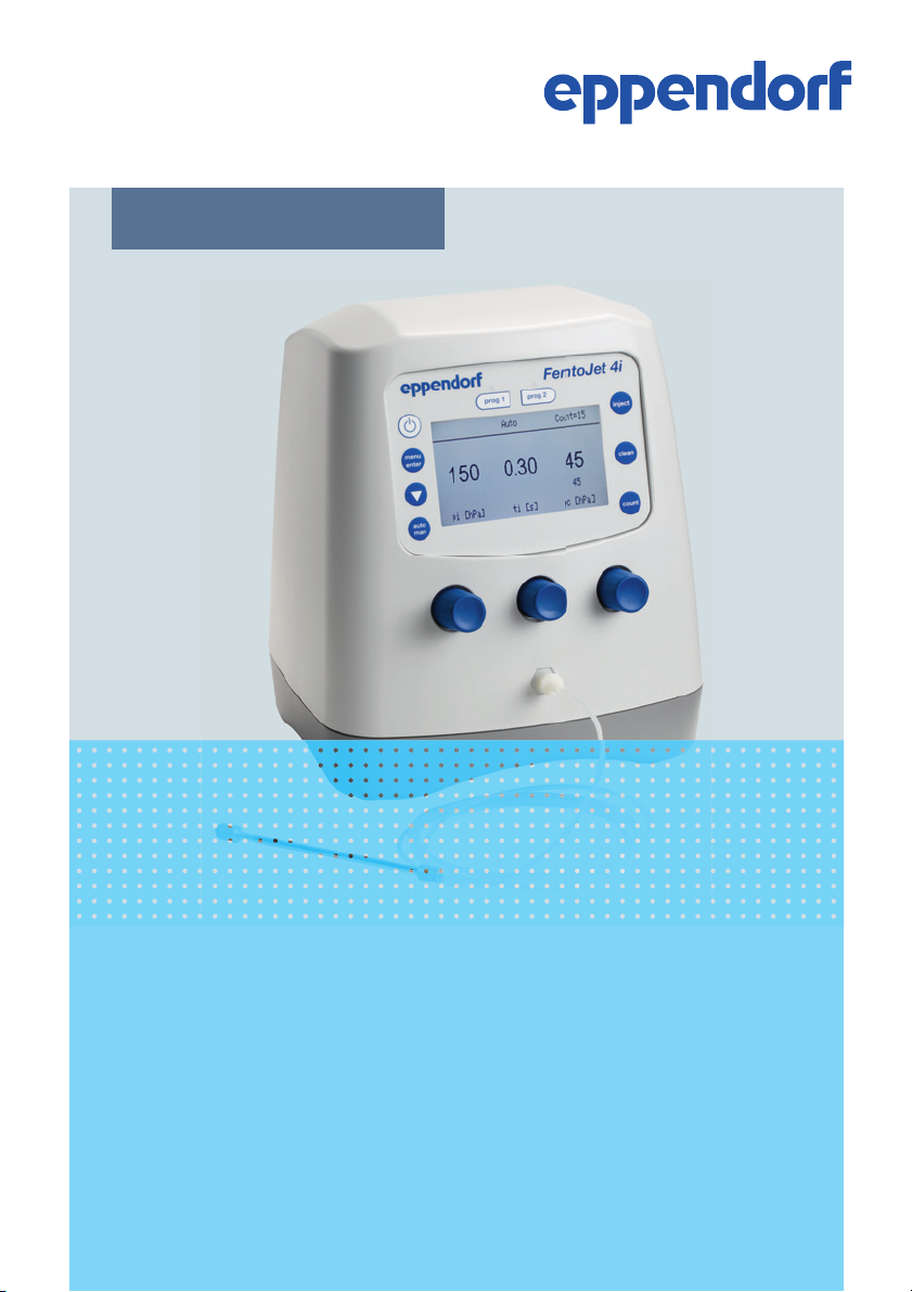
FemtoJet
Operating manual
4i
®
Page 2

Copyright © 2014 Eppendorf AG, Hamburg. All rights reserved, including graphics and
images. No part of this publication may be reproduced without the prior permission of the
copyright owner.
Eppendorf
®
and the Eppendorf logo are registered trademarks of Eppendorf AG,
Hamburg, Germany.
FemtoJet®, Femtotips®, TransferMan® and InjectMan® are registered trademarks of
Eppendorf AG, Hamburg, Germany.
Registered trademarks and protected trademarks are not marked in all cases with
®
or ™
in this manual.
5252 900.014-00/012014
Page 3

Table of contents
FemtoJet
®
4i
English (EN)
Table of contents
1 Operating instructions. . . . . . . . . . . . . . . . . . . . . . . . . . . . . . . . . . . . . . . . . . . . . . . . 7
1.1 Using this manual . . . . . . . . . . . . . . . . . . . . . . . . . . . . . . . . . . . . . . . . . . . . . . 7
1.2 Danger symbols and danger levels . . . . . . . . . . . . . . . . . . . . . . . . . . . . . . . . . 7
1.2.1 Danger symbols . . . . . . . . . . . . . . . . . . . . . . . . . . . . . . . . . . . . . . . . 7
1.2.2 Danger levels . . . . . . . . . . . . . . . . . . . . . . . . . . . . . . . . . . . . . . . . . . 7
1.3 Symbols used . . . . . . . . . . . . . . . . . . . . . . . . . . . . . . . . . . . . . . . . . . . . . . . . . 7
2 Product description . . . . . . . . . . . . . . . . . . . . . . . . . . . . . . . . . . . . . . . . . . . . . . . . . . 8
2.1 Delivery package . . . . . . . . . . . . . . . . . . . . . . . . . . . . . . . . . . . . . . . . . . . . . . . 8
2.1.1 Delivery package – Accessories. . . . . . . . . . . . . . . . . . . . . . . . . . . . 8
2.2 Features. . . . . . . . . . . . . . . . . . . . . . . . . . . . . . . . . . . . . . . . . . . . . . . . . . . . . . 8
2.3 Exemplary set-up of a microinjection system . . . . . . . . . . . . . . . . . . . . . . . . . 9
2.4 Main illustration . . . . . . . . . . . . . . . . . . . . . . . . . . . . . . . . . . . . . . . . . . . . . . 10
2.4.1 Interfaces . . . . . . . . . . . . . . . . . . . . . . . . . . . . . . . . . . . . . . . . . . . . 11
2.5 Name plate . . . . . . . . . . . . . . . . . . . . . . . . . . . . . . . . . . . . . . . . . . . . . . . . . . 12
2.6 Control panel. . . . . . . . . . . . . . . . . . . . . . . . . . . . . . . . . . . . . . . . . . . . . . . . . 13
2.7 Rotary knobs . . . . . . . . . . . . . . . . . . . . . . . . . . . . . . . . . . . . . . . . . . . . . . . . . 14
2.8 Foot control . . . . . . . . . . . . . . . . . . . . . . . . . . . . . . . . . . . . . . . . . . . . . . . . . . 15
2.9 Hand control . . . . . . . . . . . . . . . . . . . . . . . . . . . . . . . . . . . . . . . . . . . . . . . . . 15
2.10 Pressure parameters . . . . . . . . . . . . . . . . . . . . . . . . . . . . . . . . . . . . . . . . . . . 15
2.10.1 Compensation pressure p
2.10.2 Injection pressure p
2.10.3 Injection time t
2.10.4 Rinsing pressure . . . . . . . . . . . . . . . . . . . . . . . . . . . . . . . . . . . . . . 17
. . . . . . . . . . . . . . . . . . . . . . . . . . . . . . . . . . . . . . . 16
i
2.10.5 Operating pressure p
2.11 Self-calibration . . . . . . . . . . . . . . . . . . . . . . . . . . . . . . . . . . . . . . . . . . . . . . . 17
. . . . . . . . . . . . . . . . . . . . . . . . . . . . . . 16
c
. . . . . . . . . . . . . . . . . . . . . . . . . . . . . . . . . . . 16
i
. . . . . . . . . . . . . . . . . . . . . . . . . . . . . . . . . . 17
w
2.12 Universal capillary holder . . . . . . . . . . . . . . . . . . . . . . . . . . . . . . . . . . . . . . . 17
3
3 Safety . . . . . . . . . . . . . . . . . . . . . . . . . . . . . . . . . . . . . . . . . . . . . . . . . . . . . . . . . . . . 18
3.1 Intended use . . . . . . . . . . . . . . . . . . . . . . . . . . . . . . . . . . . . . . . . . . . . . . . . . 18
3.2 Warnings for intended use . . . . . . . . . . . . . . . . . . . . . . . . . . . . . . . . . . . . . . 18
3.3 Warning signs on the device . . . . . . . . . . . . . . . . . . . . . . . . . . . . . . . . . . . . . 19
3.4 User profile . . . . . . . . . . . . . . . . . . . . . . . . . . . . . . . . . . . . . . . . . . . . . . . . . . 19
3.5 Information on product liability . . . . . . . . . . . . . . . . . . . . . . . . . . . . . . . . . . 19
4 Installation . . . . . . . . . . . . . . . . . . . . . . . . . . . . . . . . . . . . . . . . . . . . . . . . . . . . . . . . 20
4.1 Preparing installation . . . . . . . . . . . . . . . . . . . . . . . . . . . . . . . . . . . . . . . . . . 20
4.1.1 Complaints about damages . . . . . . . . . . . . . . . . . . . . . . . . . . . . . . 20
4.1.2 Incomplete delivery . . . . . . . . . . . . . . . . . . . . . . . . . . . . . . . . . . . . 20
4.2 Selecting the location . . . . . . . . . . . . . . . . . . . . . . . . . . . . . . . . . . . . . . . . . . 20
4.3 Connecting the Microinjector . . . . . . . . . . . . . . . . . . . . . . . . . . . . . . . . . . . . 20
Page 4

Table of con tents
FemtoJet
4
®
4i
English (EN)
4.4 Connecting an external device . . . . . . . . . . . . . . . . . . . . . . . . . . . . . . . . . . . 20
4.4.1 Connecting a micromanipulator . . . . . . . . . . . . . . . . . . . . . . . . . . 21
4.4.2 Connecting the PC . . . . . . . . . . . . . . . . . . . . . . . . . . . . . . . . . . . . . 21
4.4.3 Connecting two devices. . . . . . . . . . . . . . . . . . . . . . . . . . . . . . . . . 22
4.5 Connecting accessories. . . . . . . . . . . . . . . . . . . . . . . . . . . . . . . . . . . . . . . . . 22
4.5.1 Connecting a foot control . . . . . . . . . . . . . . . . . . . . . . . . . . . . . . . 22
4.5.2 Connecting a hand control . . . . . . . . . . . . . . . . . . . . . . . . . . . . . . 22
5 Software . . . . . . . . . . . . . . . . . . . . . . . . . . . . . . . . . . . . . . . . . . . . . . . . . . . . . . . . . . 23
5.1 Main screen. . . . . . . . . . . . . . . . . . . . . . . . . . . . . . . . . . . . . . . . . . . . . . . . . . 23
5.2 Main menu . . . . . . . . . . . . . . . . . . . . . . . . . . . . . . . . . . . . . . . . . . . . . . . . . . 24
5.3 Navigating the menu . . . . . . . . . . . . . . . . . . . . . . . . . . . . . . . . . . . . . . . . . . . 24
5.3.1 Selecting the menu and navigating . . . . . . . . . . . . . . . . . . . . . . . . 24
5.3.2 Exiting the menu . . . . . . . . . . . . . . . . . . . . . . . . . . . . . . . . . . . . . . 24
5.3.3 Selecting parameters . . . . . . . . . . . . . . . . . . . . . . . . . . . . . . . . . . . 25
5.3.4 Changing a parameter value . . . . . . . . . . . . . . . . . . . . . . . . . . . . . 25
6 Operation . . . . . . . . . . . . . . . . . . . . . . . . . . . . . . . . . . . . . . . . . . . . . . . . . . . . . . . . . 26
6.1 Switching on or off the Microinjector . . . . . . . . . . . . . . . . . . . . . . . . . . . . . . 26
6.1.1 Switching on the Microinjector . . . . . . . . . . . . . . . . . . . . . . . . . . . 26
6.1.2 Switching off the Microinjector . . . . . . . . . . . . . . . . . . . . . . . . . . . 26
6.2 Switching on or off the standby mode . . . . . . . . . . . . . . . . . . . . . . . . . . . . . 26
6.2.1 Switching on the standby mode . . . . . . . . . . . . . . . . . . . . . . . . . . 26
6.2.2 Switching off the standby mode . . . . . . . . . . . . . . . . . . . . . . . . . . 27
6.3 Determining the injection parameters . . . . . . . . . . . . . . . . . . . . . . . . . . . . . 27
6.3.1 Filling the capillaries with fluorescence dye . . . . . . . . . . . . . . . . . 27
6.3.2 Carrying out a test injection . . . . . . . . . . . . . . . . . . . . . . . . . . . . . 27
6.3.3 Possible sources of error - cell inflates or bursts . . . . . . . . . . . . . 28
6.3.4 Possible sources of error - capillary is clogged. . . . . . . . . . . . . . . 28
6.3.5 Possible sources of error - liquid is not being injected . . . . . . . . . 28
6.3.6 Possible sources of error - capillary does not reach the cell. . . . . 28
6.3.7 Result – the injection parameters have been determined . . . . . . . 28
6.4 Setting the compensation pressure p
6.5 Setting the injection pressure p
6.6 Setting the injection time t
6.7 Setting the injection mode . . . . . . . . . . . . . . . . . . . . . . . . . . . . . . . . . . . . . . 30
. . . . . . . . . . . . . . . . . . . . . . . . . . . . . . . . . . . . . . 29
i
. . . . . . . . . . . . . . . . . . . . . . . . . . . . . 29
c
. . . . . . . . . . . . . . . . . . . . . . . . . . . . . . . . . . 29
i
6.7.1 Setting the automatic injection mode . . . . . . . . . . . . . . . . . . . . . . 30
6.7.2 Setting the manual injection mode . . . . . . . . . . . . . . . . . . . . . . . . 30
6.8 Injecting liquid . . . . . . . . . . . . . . . . . . . . . . . . . . . . . . . . . . . . . . . . . . . . . . . 30
6.8.1 Automatically injecting liquid . . . . . . . . . . . . . . . . . . . . . . . . . . . . 30
6.8.2 Manually injecting liquid . . . . . . . . . . . . . . . . . . . . . . . . . . . . . . . . 31
6.9 Replacing the capillary . . . . . . . . . . . . . . . . . . . . . . . . . . . . . . . . . . . . . . . . . 31
6.10 Rinsing the capillary . . . . . . . . . . . . . . . . . . . . . . . . . . . . . . . . . . . . . . . . . . . 31
6.11 Setting the injection counter to zero. . . . . . . . . . . . . . . . . . . . . . . . . . . . . . . 31
Page 5

Table of contents
FemtoJet
®
English (EN)
6.12 Calling up saved injection parameters . . . . . . . . . . . . . . . . . . . . . . . . . . . . . 32
6.12.1 Calling up saved injection parameters . . . . . . . . . . . . . . . . . . . . . 32
6.13 Saving or changing the injection parameters . . . . . . . . . . . . . . . . . . . . . . . . 32
6.13.1 Saving injection parameters . . . . . . . . . . . . . . . . . . . . . . . . . . . . . 32
6.13.2 Changing the saved injection parameters . . . . . . . . . . . . . . . . . . . 33
6.14 Adjusting the device settings . . . . . . . . . . . . . . . . . . . . . . . . . . . . . . . . . . . . 33
6.14.1 Change capillary function – Changing the capillary . . . . . . . . . . . 33
6.14.2 Pressure unit function – Selecting the pressure unit . . . . . . . . . . 33
6.14.3 Beeper function – Switching on/off the signal tone . . . . . . . . . . . 33
6.14.4 Contrast function – Setting the display contrast . . . . . . . . . . . . . . 33
6.14.5 Illumination function – Switching on/off the
display illumination . . . . . . . . . . . . . . . . . . . . . . . . . . . . . . . . . . . . 34
6.14.6 Continuous flow function – Setting the constant
operating pressure. . . . . . . . . . . . . . . . . . . . . . . . . . . . . . . . . . . . . 34
6.14.7 Drain pressure supply function – Draining the
pressure reservoir . . . . . . . . . . . . . . . . . . . . . . . . . . . . . . . . . . . . . 34
6.15 Inserting the capillary into the capillary holder . . . . . . . . . . . . . . . . . . . . . . 35
6.16 Inserting Femtotips into the capillary holder . . . . . . . . . . . . . . . . . . . . . . . . 35
7 Troubleshooting. . . . . . . . . . . . . . . . . . . . . . . . . . . . . . . . . . . . . . . . . . . . . . . . . . . . 36
7.1 General errors . . . . . . . . . . . . . . . . . . . . . . . . . . . . . . . . . . . . . . . . . . . . . . . . 36
7.2 Error messages . . . . . . . . . . . . . . . . . . . . . . . . . . . . . . . . . . . . . . . . . . . . . . . 36
7.2.1 Error 01 – 10 . . . . . . . . . . . . . . . . . . . . . . . . . . . . . . . . . . . . . . . . . 36
7.2.2 Error 11 – 18 . . . . . . . . . . . . . . . . . . . . . . . . . . . . . . . . . . . . . . . . . 37
7.2.3 Error 19 – 38 . . . . . . . . . . . . . . . . . . . . . . . . . . . . . . . . . . . . . . . . . 39
7.2.4 Error 39 – 40 . . . . . . . . . . . . . . . . . . . . . . . . . . . . . . . . . . . . . . . . . 40
4i
5
8 Maintenance. . . . . . . . . . . . . . . . . . . . . . . . . . . . . . . . . . . . . . . . . . . . . . . . . . . . . . . 41
8.1 Replacing the sealings in the grip head . . . . . . . . . . . . . . . . . . . . . . . . . . . . 41
8.1.1 Removing the sealing washer and o-rings . . . . . . . . . . . . . . . . . . 41
8.1.2 Inserting the o-rings and the sealing washer . . . . . . . . . . . . . . . . 42
8.2 Replacing the sealing in the adapter for Femtotips . . . . . . . . . . . . . . . . . . . 42
8.2.1 Replacing the o-ring . . . . . . . . . . . . . . . . . . . . . . . . . . . . . . . . . . . 42
8.3 Replacing fuses . . . . . . . . . . . . . . . . . . . . . . . . . . . . . . . . . . . . . . . . . . . . . . . 43
8.4 Cleaning . . . . . . . . . . . . . . . . . . . . . . . . . . . . . . . . . . . . . . . . . . . . . . . . . . . . 43
8.5 Hints with regard to service intervals . . . . . . . . . . . . . . . . . . . . . . . . . . . . . . 44
8.6 Service and maintenance . . . . . . . . . . . . . . . . . . . . . . . . . . . . . . . . . . . . . . . 44
8.7 Disinfection/decontamination . . . . . . . . . . . . . . . . . . . . . . . . . . . . . . . . . . . . 44
Page 6

Table of con tents
FemtoJet
6
®
4i
English (EN)
9 Technical data . . . . . . . . . . . . . . . . . . . . . . . . . . . . . . . . . . . . . . . . . . . . . . . . . . . . . 45
9.1 Mode of operation . . . . . . . . . . . . . . . . . . . . . . . . . . . . . . . . . . . . . . . . . . . . . 45
9.2 Weight/dimensions . . . . . . . . . . . . . . . . . . . . . . . . . . . . . . . . . . . . . . . . . . . . 45
9.3 Power supply. . . . . . . . . . . . . . . . . . . . . . . . . . . . . . . . . . . . . . . . . . . . . . . . . 45
9.4 Interfaces. . . . . . . . . . . . . . . . . . . . . . . . . . . . . . . . . . . . . . . . . . . . . . . . . . . . 45
9.4.1 USB . . . . . . . . . . . . . . . . . . . . . . . . . . . . . . . . . . . . . . . . . . . . . . . . 45
9.4.2 RS 232 . . . . . . . . . . . . . . . . . . . . . . . . . . . . . . . . . . . . . . . . . . . . . . 45
9.5 Ambient conditions . . . . . . . . . . . . . . . . . . . . . . . . . . . . . . . . . . . . . . . . . . . . 47
10 Transport, storage and disposal . . . . . . . . . . . . . . . . . . . . . . . . . . . . . . . . . . . . . . . 48
10.1 Storage . . . . . . . . . . . . . . . . . . . . . . . . . . . . . . . . . . . . . . . . . . . . . . . . . . . . . 48
10.2 Decontamination before shipment . . . . . . . . . . . . . . . . . . . . . . . . . . . . . . . . 48
10.3 Transport . . . . . . . . . . . . . . . . . . . . . . . . . . . . . . . . . . . . . . . . . . . . . . . . . . . . 48
10.4 Disposal. . . . . . . . . . . . . . . . . . . . . . . . . . . . . . . . . . . . . . . . . . . . . . . . . . . . . 49
11 Ordering information. . . . . . . . . . . . . . . . . . . . . . . . . . . . . . . . . . . . . . . . . . . . . . . . 50
11.1 FemtoJet 4i . . . . . . . . . . . . . . . . . . . . . . . . . . . . . . . . . . . . . . . . . . . . . . . . . . 50
11.2 Accessories . . . . . . . . . . . . . . . . . . . . . . . . . . . . . . . . . . . . . . . . . . . . . . . . . . 50
11.3 Universal capillary holder and accessories. . . . . . . . . . . . . . . . . . . . . . . . . . 50
Index . . . . . . . . . . . . . . . . . . . . . . . . . . . . . . . . . . . . . . . . . . . . . . . . . . . . . . . . . . . . . 51
Page 7
Operating instructions
FemtoJet
English (EN)
®
4i
1 Operating instructions
1.1 Using this manual
Read this operating manual completely before using the device for the first time. Also
observe the instructions for use of the accessories.
This operating manual is part of the product. Thus, it must always be easily accessible.
Enclose this operating manual when transferring the device to third parties.
You will find the current version of the operating manual for all available languages on
our webpage under www.eppendorf.com
1.2 Danger symbols and danger levels
The safety instructions of this operating manual indicate the following danger symbols
and danger levels:
1.2.1 Danger symbols
Electric shock Hazard point
Cuts Material damage
Biohazard
.
7
1.2.2 Danger levels
DANGER Will lead to severe injuries or death.
WAR NIN G May lead to severe injuries or death.
CAUTION May lead to light to moderate injuries.
NOTICE May lead to material damage.
1.3 Symbols used
Depiction Meaning
1.
2.
Actions in the specified order
Actions without a specified order
• List
Text Display text or software text
Direction of movement
Additional information
Page 8

Product description
FemtoJet
8
®
4i
English (EN)
2 Product description
2.1 Delivery package
Number Description
1 FemtoJet 4i
1Mains/power cord
1Injection tube
1 Operating manual
2.1.1 Delivery package – Accessories
Number Description
1 Universal capillary holder
1 Grip head 0 for capillary (outer diameter 1.0 mm to 1.1 mm)
1 Adapter for Femtotips
1 Foot control
2.2 Features
The Microinjector can be used to inject very small amounts of fluid into cells. The
parameters for pressure and time are set on the device and controlled by the software. It
is possible to trigger the injection on the Microinjector or on a connected
micromanipulator by Eppendorf. The semiautomatic injection movement is controlled by
the Microinjector or the micromanipulator. The required pressure is generated by a
soundproof internal compressor.
Page 9
2.3 Exemplary set-up of a microinjection system
FemtoJet
inject
prog 1
prog 2
count
clean
menu
enter
auto
man
2
1
3
6
5
4
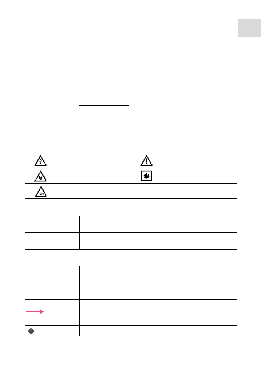
Abb. 2-1:Microinjection system with FemtoJet 4i
Product description
FemtoJet
®
4i
English (EN)
9
Fig. 2-1: Microinjection system with FemtoJet 4i
1 Micromanipulator InjectMan 4
2 Universal capillary holder with
capillary
3Inverse microscope
4 Injection tube
5Control board InjectMan 4
6 Microinjector FemtoJet 4i
Page 10

Product description
menu
enter
auto
man
inject
clean
count
prog 1
prog 2
FemtoJet
1
2
4
5 763
FemtoJet
10
®
4i
English (EN)
2.4 Main illustration
Abb. 2-2:Front and rear side
Fig. 2-2: Front and rear side
1Display
2 Control panel
3 Port for injection tube
4 Rotary knobs for injection parameters
5 Name plate
Lower side of device
6Interfaces
7Venting
Lower side of device
Page 11
2.4.1 Interfaces
MANIPULATOR
FOOT SWITCH
SERVICE
4
5
6
213
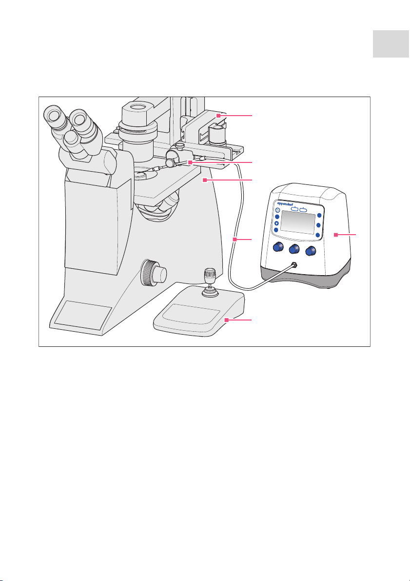
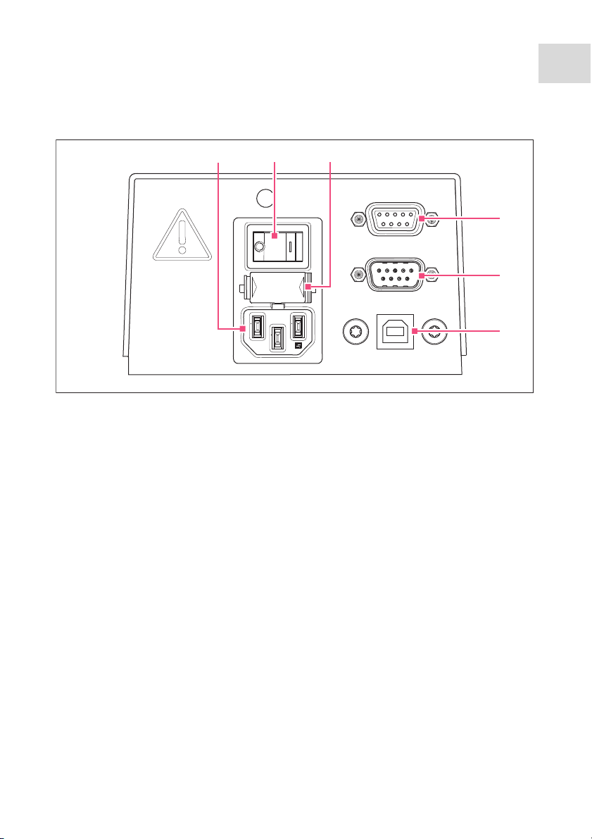
Abb. 2-3:Interfaces
Fig. 2-3: Interfaces
Product description
FemtoJet
®
4i
English (EN)
11
1 Mains/power connection
2Mains/power switch On/Off
3Micro fuse
4 Port for micromanipulator or
computer
5 Connection for foot or hand control
6 Service connection
Page 12
Product description
1
2
3
4
5
6
7
8
10
9
FemtoJet
12
English (EN)
®
4i
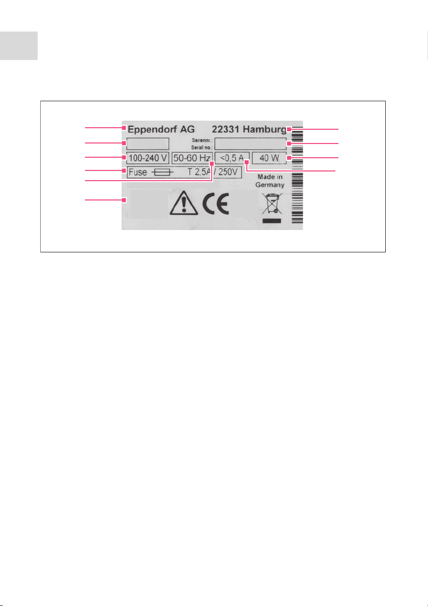
2.5 Name plate
Abb. 2-4:Name plate
Fig. 2-4: Name plate
1 Manufacturer
2Product number
3Voltage
4Micro fuse
5Frequency
6Labelings
7Address of manufacturer
8 Serial number
9Output
10 Current consumption
Page 13

Product description
countcountcount
clean
prog 1
5 6
7
8
9
4
3
2
1
FemtoJet
English (EN)
2.6 Control panel
The keys of the control panel are used to switch on the Microinjector, to perform
functions, to select programs and to navigate through the menu.
Abb. 2-5:Control panel
®
4i
13
Fig. 2-5: Control panel
1 standby key
Activate/deactivate standby mode
2 menu enter key
Open the menu
3Arrow key
Navigate the menu
4 auto man key
Toggle between automatic and manual
6 prog 2 key
Select or save parameter set 2
7 inject key
Perform an injection
8 clean key
Clean the capillary
9 count key
Set the counter to zero
injection
5 prog 1 key
Select or save parameter set 1
Page 14

Product description
enter
FemtoJet
14
®
4i
English (EN)
2.7 Rotary knobs
The rotary knobs are used to set the injection parameters as injection time, injection
pressure and compensation pressure.
Abb. 2-6:Rotary knobs
cleanclean
auto
man
Fig. 2-6: Rotary knobs
1 Rotary knob
Set the injection pressure p
2 Rotary knob
Set the injection time t
countcountcountcount
321
3Rotary knob
i
i
Set the compensation pressure p
c
Page 15

2.8 Foot control
You can connect the foot control to the Microinjector.
The foot control corresponds to the following key on the Microinjector:
• Foot control – inject key
Product description
FemtoJet
®
4i
English (EN)
15
Abb. 2-7:Foot control with plug
Fig. 2-7: Foot control with plug
2.9 Hand control
The hand control is not included in the delivery package and must be ordered
separately.
You can connect the hand control to the Microinjector.
The hand controls correspond to the following keys on the Microinjector:
• Left hand control – inject key
• Right hand control – clean key
The inject and clean keys remain active when the hand control is connected.
2.10 Pressure parameters
The parameters are used to define the pressure and time for the injection and the
cleaning of the capillary.
The pressure parameters include the following parameters:
The inject key remains active when the foot control is connected.
• Compensation pressure – p
• Injection pressure – p
• Injection time – t
i
c
i
• Operating pressure
• Rinsing pressure
Page 16

Product description
3
4
5
1
2
FemtoJet
16
®
English (EN)
4i
2.10.1 Compensation pressure p
c
The compensation pressure prevents the liquid from rising from the Petri dish into the
capillary due to the capillary action. Due to the compensation pressure, some liquid will
leak constantly from the capillary tip. This prevents the injection material from clumping
together.
Abb. 2-8:Pressure ratios in the capillary
Fig. 2-8: Pressure ratios in the capillary
1Capillary
2 Liquid with injection material
3 Compensation pressure p
c
4Hydrostatic pressure
5 Capillary action
2.10.2 Injection pressure p
i
The injection pressure defines the pressure used for injecting liquid into the cell. During
the injection process, the injection pressure is applied as long as the injection time is
running. To inject liquid into a cell, the injection pressure must be higher than the inside
pressure of the cell.
2.10.3 Injection time t
i
The injection time defines the time period for injecting the liquid. The start of the
injection time depends on the presettings of the micromanipulator. The injection time
begins either when triggering the injection function or when reaching the lower safety
limit. The injection pressure is applied as long as the injection time is running.
Page 17

2.10.4 Rinsing pressure
1 2 3 4
6 7
5
The rinsing pressure is used to clean the capillary.
Product description
FemtoJet
®
4i
English (EN)
17
2.10.5 Operating pressure p
w
The operating pressure subsumes the injection pressure, compensation pressure and
rinsing pressure.
2.11 Self-calibration
The Microinjector performs a calibration every two hours. During the calibration, the
ventilation valve opens and the collected condensation water is discharged.
2.12 Universal capillary holder
You can insert a capillary or a Femtotip into the universal capillary holder.
Abb. 2-9:Universal capillary holder
Fig. 2-9: Universal capillary holder
1Capillary
2Grip head
3Knurled screw
5 Connection for injection tube
6Femtotips
7 Adapter for Femtotips
4 Universal capillary holder
Page 18

Safety
FemtoJet
18
English (EN)
®
4i
3Safety
3.1 Intended use
The FemtoJet 4i Microinjector is designed and manufactured for the exclusive use within
the context of biologial, chemical and physical research.
Together with the micromanipulator and the capillary, the Microinjector forms a
microinjection system. The Microinjector is used for the precise and reproducible
injection of extremely small amounts of fluid (femto liter to micro liter range) in biological
cells or nuclei.
The Microinjector is intended exclusively for indoor use and for operation by qualified
staff.
3.2 Warnings for intended use
WARNING! Risk of injury due to flying capillaries and glass splinters.
If exposed to high pressures, capillaries may detach themselves from the grip
heads and become projectiles.
Capillaries can crack as a result of incorrect handling.
Wear protective goggles.
Never aim capillaries at people.
Use capillaries with an outer diameter that matches the grip head
specifications.
Always mount / dismount capillaries when they are depressurized.
Mount the capillary correctly in the grip head.
Do not touch the capillary with the Petri dish or other objects.
CAUTION! Risk of cuts from broken capillaries.
Capillaries are made of glass and are very fragile.
Wear your personal protective equipment (PPE).
Always mount capillaries depressurized.
Never aim capillaries at people.
Handle the capillaries very carefully.
Page 19

Safety
FemtoJet
English (EN)
WARNING! Damage to health due to infectious liquids and pathogenic
germs.
®
4i
When handling infectious liquids and pathogenic germs, observe the national
regulations, the biological security level of your laboratory, the material safety
data sheets, and the manufacturer's application notes.
Wear personal protective equipment.
For full instructions regarding the handling of germs or biological material of
risk group II or higher, please refer to the "Laboratory Biosafety Manual"
(Source: World Health Organization, current edition of the Laboratory
Biosafety Manual).
3.3 Warning signs on the device
Warning symbol Meaning
Read the operating manual
3.4 User profile
The device and accessories may only be operated by trained and skilled personnel.
Before using the device, read the operating manual carefully and familiarize yourself with
the device's mode of operation.
19
3.5 Information on product liability
In the following cases, the designated protection of the device may be compromised.
Liability for any resulting property damage or personal injury is then transferred to the
operator:
• The device is not used in accordance with the operating manual.
• The device is used outside of its intended use.
• The device is used with accessories or consumables which are not recommended by
Eppendorf.
• The device is maintained or repaired by people not authorized by Eppendorf.
• The user makes unauthorized changes to the device.
Page 20

Installation
FemtoJet
20
English (EN)
®
4i
4 Installation
4.1 Preparing installation
Store the packaging for later transport or storage.
In case of visible damages on the Microinjector or the packaging, do not
commission the Microinjector.
1. Check the packaging for damage.
2. Check that everything is included in the delivery.
3. Check the Microinjector and the accessories for damages.
4.1.1 Complaints about damages
Contact your local Eppendorf distribution partner.
4.1.2 Incomplete delivery
Contact your local Eppendorf distribution partner.
4.2 Selecting the location
Please select the location for the Microinjector according to the following criteria:
• Suitable mains/power connection in accordance with the name plate.
• A bench with a horizontal and even work surface which is designed to support the
weight of the Microinjector.
The mains/power switch and cutting unit of the mains/power line must be easily
accessible during operation (e.g., residual current circuit breaker).
4.3 Connecting the Microinjector
Prerequisites
• Electrical connection data according to the name plate.
• The Microinjector is switched off.
Connect the power cable.
4.4 Connecting an external device
The following devices can be connected to the Microinjector:
• Micromanipulator (InjectMan 4, TransferMan 4r or InjectMan NI 2)
•Computer
Page 21

4.4.1 Connecting a micromanipulator
Prerequisites
• Y-cable FJ4 is available.
• The Microinjector is switched off.
• The micromanipulator is switched off.
The operation is described in the manual for the micromanipulator.
1. Connect the Y-cable to the MANIPULATOR port.
2. Connect the micromanipulator to the Y-cable.
3. Switch on the Microinjector.
The initialization phase starts.
After completion of the initialization phase, the main screen appears.
4.4.2 Connecting the PC
Prerequisites
• Y-cable FJ4 is available.
• Devices are switched off.
Control with a PC is described in the Cell Technology · PC Control manual.
1. Connect the Y-cable to the MANIPULATOR port.
2. Connect the computer to the Y-cable.
3. Switch on the Microinjector.
The initialization phase starts.
After completion of the initialization phase, the main screen appears.
Installation
FemtoJet
®
4i
English (EN)
21
Page 22

Installation
FemtoJet
22
English (EN)
®
4i
4.4.3 Connecting two devices
Prerequisites
• Y-cable FJ4 is available.
• Devices are switched off.
Two devices can be connected with the Y-cable FJ4.
The following combinations are possible:
•Computer
• Micromanipulator
Control with a PC is described in the Cell Technology · PC Control manual.
The operation is described in the manual for the micromanipulator.
1. Connect the Y-cable to the MANIPULATOR port.
2. Connect the computer to the Y-cable.
3. Connect the micromanipulator to the Y-cable.
4. Switch on the Microinjector.
The initialization phase starts.
After completion of the initialization phase, the main screen appears.
4.5 Connecting accessories
It is possible to connect the following accessories to the Microinjector:
• Foot control or
•Hand control
4.5.1 Connecting a foot control
Prerequisites
• The Microinjector is switched off.
1. Connect the foot control to the FOOT SWITCH port.
4.5.2 Connecting a hand control
Prerequisites
• The Microinjector is switched off.
• No foot control has been connected.
The hand control is not included in the delivery package and must be ordered
separately.
Connect the hand control to the FOOT SWITCH port.
Page 23

Software
6
7
3
4 5
1
2
FemtoJet
®
4i
English (EN)
5 Software
5.1 Main screen
The main screen displays all injection parameters, the selected pressure unit, the injection
mode and the number of injections.
Abb. 5-1:Main screen splitting
Fig. 5-1: Main screen splitting
23
1Injection mode
Automatic or manual injection
2 Injection counter
3 Parameter for injection pressure p
Pressure unit in hPa or PSI
4 Parameter for injection time t
Time in seconds
i
5 Parameter for compensation pressure
p
c
Pressure unit in hPa or PSI
6 Line with set values
i
7 Line with actual values
Page 24

24
Software
FemtoJet
®
4i
English (EN)
5.2 Main menu
Abb. 5-2:Main menu
Fig. 5-2: Main menu
Menu Parameter
Change capillary Replace the capillary
Pressure unit Set the unit for pressure (hPa or PSI)
Beeper Switch on/off the signal tone
Contrast Set the display contrast
Illumination Switch on/off the display illumination
Continuous flow Set a fixed value for a continuous pressure
Drain pressure supply Open the venting for a short time and discharge the
condensation water
5.3 Navigating the menu
5.3.1 Selecting the menu and navigating
5.3.2 Exiting the menu
1. Select the submenu Back.
2. Press the menu enter key.
The main screen appears.
1. Press the menu enter key.
The menu appears.
2. To select a menu entry, press the arrow
key.
The menu entry is shown with a black
bar.
Page 25

5.3.3 Selecting parameters
Prerequisites
•A submenu with parameters is selected.
1. To select a parameter, press the arrow
2. Confirm with the menu enter key.
5.3.4 Changing a parameter value
Prerequisites
• A submenu with parameter values is selected.
Software
FemtoJet
®
English (EN)
key.
The selected parameter is marked with a
check mark.
The main screen appears.
4i
25
1. For changing a value, use the rotary knob.
2. Confirm with the menu enter key.
The main screen appears.
Page 26

Operation
FemtoJet
26
English (EN)
®
4i
6Operation
6.1 Switching on or off the Microinjector
WARNING! Electric shock due to damage to device or mains cable.
Only switch on the device if the device and mains cable are undamaged.
Only use devices that have been properly installed or repaired.
In case of danger, disconnect the device from the mains supply by pulling the
power plug from the device or the mains socket or, by using the isolating
device intended for this purpose (e.g., emergency stop switch in the
laboratory).
6.1.1 Switching on the Microinjector
1. Take off the injection tube.
2. Switch on the Microinjector with the mains/power switch.
The Microinjector performs a self test.
The operating pressure is built up.
The main screen appears.
6.1.2 Switching off the Microinjector
1. Keep the standby key pressed.
The message Hold Standby to exhaust appears.
The pressure reservoir is emptied.
2. Switch off the Microinjector with the mains/power switch.
6.2 Switching on or off the standby mode
For short intermissions, you can use the standby mode. The Microinjector remains ready
for operation.
6.2.1 Switching on the standby mode
1. Press the standby key.
2. Take off the injection tube.
The display shows STANDBY.
The operating controls are deactivated.
The pressure in the pressure reservoir is maintained.
Page 27

Operation
FemtoJet
English (EN)
6.2.2 Switching off the standby mode
Prerequisites
• The display shows STANDBY.
1. Take off the injection tube.
2. Press the standby key.
The Microinjector performs a short self test.
The display shows the main screen.
6.3 Determining the injection parameters
To determine the correct injection parameters, you can carry out a test injection with
fluorescence dye.
6.3.1 Filling the capillaries with fluorescence dye
Prerequisites
• Use a capillary with an opening of 0.5 μm.
• The injection tube is mounted to the universal capillary holder.
• Pipette with Microloader by Eppendorf is available.
1. Fill the Microloader with fluorescing liquid.
2. Equip the capillary with the Microloader.
3. Insert the capillary into the universal capillary holder.
®
4i
27
6.3.2 Carrying out a test injection
Prerequisites
• The Microinjector and the micromanipulator are connected and ready for operation.
• The universal capillary holder is prepared with a capillary and fluorescence dye.
• The universal capillary holder is clamped in the Eppendorf micromanipulator.
• The Petri dish with adherent cells is prepared.
1. Connect the injection tube to the Microinjector.
2. Define the lower safety limit on the micromanipulator.
3. Position the capillary above the cell.
4. Press the prog 1 key.
5. Press the inject key.
6. Check the injection visually.
Page 28

28
Operation
FemtoJet
®
4i
English (EN)
6.3.3 Possible sources of error - cell inflates or bursts
The injected volume is too large.
A volume increase of about 10 % is an appropriate guide value for adherent
cells.
1. Decrease the injection pressure or the injection time.
2. Repeat the test injection.
6.3.4 Possible sources of error - capillary is clogged
The injection material has clumped together or an old capillary was used.
1. Press the clean key.
2. Repeat the test injection.
3. Replace the capillary if it is not possible to clean it by rinsing.
6.3.5 Possible sources of error - liquid is not being injected
The interior cell pressure is higher than the injection pressure.
1. Increase the injection pressure.
2. Repeat the test injection.
6.3.6 Possible sources of error - capillary does not reach the cell
The cell is below the lower safety limit (Z-axis Limit) of the micromanipulator.
1. Adjust the lower safety limit on the micromanipulator.
2. Repeat the test injection.
6.3.7 Result – the injection parameters have been determined
If the correct injection parameters for the current test set-up have been determined, you
can continue by performing the injection or you can save the parameter set.
• Saving the injection parameters – (see Saving or changing the injection parameters on
p. 32)
• Performing the injection – (see Injecting liquid on p. 30)
Page 29

Operation
FemtoJet
®
4i
English (EN)
6.4 Setting the compensation pressure pc
The compensation pressure depends on the surface tension, the viscosity of the injection
liquid and the diameter of the capillary opening. The setting of the compensation pressure
must provide for a continuous slight leak of liquid at the capillary tip.
Prerequisites
• The injection parameters are known.
• Use a capillary with an opening of 0.5 μm.
Set the compensation pressure p
The actual value is shown below the set value.
with the rotary knob.
c
The set value is displayed.
6.5 Setting the injection pressure pi
The set injection pressure must be higher than the inside pressure of the cell. The
injection pressure is built up from the start of the injection time.
Prerequisites
• The injection parameters are known.
• Use a capillary with an opening of 0.5 μm.
Guide values for the injection pressure are 50 hPa to 500 hPa (0.73 PSI to 7.20
PSI).
Set the injection pressure p
with the rotary knob.
i
29
6.6 Setting the injection time ti
The injection time and the injection pressure determine the injected volume. The moment
from which the injection time is counted depends on the set synchronization mode on the
connected micromanipulator.
Beginning of time measurement during synchronization mode:
• IMMEDIATE – directly after triggering the injection
• LIMIT – when the lower safety limit is reached
Prerequisites
• The injection parameters are known.
Guide values for the injection time are 0.3 – 1.5 seconds.
Set the injection time t
with the rotary knob.
i
Page 30

Operation
FemtoJet
30
English (EN)
®
4i
6.7 Setting the injection mode
6.7.1 Setting the automatic injection mode
During the automatic injection mode, the set injection time is used. During the injection,
the time elapses in reverse and the injection stops at zero.
Press the auto man key.
The Auto injection mode is displayed.
The injection time is displayed.
6.7.2 Setting the manual injection mode
During the manual injection mode, no preset injection time is used. The injection only
stops when releasing the inject key.
Press the auto man key.
The Manual injection mode is displayed.
The injection time only is displayed
when pressing the inject key.
6.8 Injecting liquid
You can trigger an injection with the inject key, the foot control or the hand control.
6.8.1 Automatically injecting liquid
Prerequisites
• The display shows Auto.
• The injection parameters are set.
• The micromanipulator is connected.
• For the synchronization, IMMEDIATE is set on the micromanipulator.
Page 31

Press the inject key.
The injection movement is triggered on the micromanipulator.
The inject key is disabled during the injection.
The elapsing injection time is displayed.
6.8.2 Manually injecting liquid
Prerequisites
• The injection parameters are set.
• The micromanipulator is connected.
• For the synchronization, IMMEDIATE is set on the micromanipulator.
1. Press the auto man key.
The display shows Manual.
2. Keep the inject key pressed.
The injection of the liquid continues until the inject key is released.
The progress of the injection time is displayed.
6.9 Replacing the capillary
1. Press the menu enter key.
2. Select the Change capillary menu.
3. Confirm with the menu enter key.
The message Capillary may be changed now is displayed.
The valve on the injection tube is closed.
4. Replace the capillary on the micromanipulator.
5. Press the menu enter key.
The main screen appears.
Operation
FemtoJet
English (EN)
®
4i
31
6.10 Rinsing the capillary
You can rinse a clogged capillary using the cleaning function.
1. Keep the clean key pressed.
The rinsing of the capillary continues until you release the clean key.
The capillary is rinsed at maximum pressure.
The pressure build-up is shown in a chart.
6.11 Setting the injection counter to zero
For each injection performed, the counter is increased by one. You can reset the counter
to zero.
1. Press the count key.
The Count display is reset to zero.
Page 32

32
Operation
FemtoJet
®
4i
English (EN)
6.12 Calling up saved injection parameters
The program keys are predefined with exemplary parameter sets for standard
applications. One parameter set consists of injection pressure, injection time,
compensation pressure and injection mode.
The parameter sets are suited for the following standard applications:
• prog 1 – For adherent cell injection with a capillary diameter of approx. 0.5 μm.
• prog 2 – For pronucleus injection with a capillary diameter of approx. 0.5 μm.
Parameter set Injection pressure
p
i
Injection time
t
i
Compensation
pressure
p
c
Injection mode
prog 1 150 hPa 0.30 s 50 hPa Auto
2.18 PSI 0.30 s 0.73 PSI
prog 2 110 hPa – 15 hPa Manual
1.60 PSI – 0.22 PSI
6.12.1 Calling up saved injection parameters
1. Press the prog 1 or prog 2 key.
An acoustic signal will sound.
The LED above the program key is illuminated.
The selected program is active.
The parameter set is displayed.
6.13 Saving or changing the injection parameters
You can save individual injection parameters on the two program slots. One parameter set
consists of injection pressure, injection time, compensation pressure and injection mode.
6.13.1 Saving injection parameters
The current parameter set is overwritten. For the ex factory parameter sets, refer
to chapter “Calling up saved injection parameters” on page 32.
1. Set the injection parameters.
2. Select the injection mode automatically or manually.
3. Keep the prog 1 or prog 2 key pressed for approx. two seconds.
An acoustic signal will sound.
The LED above the program key is illuminated.
The injection parameters are saved.
Page 33

6.13.2 Changing the saved injection parameters
The current parameter set is overwritten. For the ex factory parameter sets, refer
to chapter “Calling up saved injection parameters” on page 32.
1. Change the injection parameters.
2. Keep the prog 1 or prog 2 key pressed for two seconds.
An acoustic signal will sound.
The LED above the program key is illuminated.
The new value is saved.
6.14 Adjusting the device settings
6.14.1 Change capillary function – Changing the capillary
1. Press the menu enter key.
2. Select the Change capillary menu.
3. Confirm with the menu enter key.
You can change the capillary.
4. Quit the menu with the menu enter key.
6.14.2 Pressure unit function – Selecting the pressure unit
1. Press the menu enter key.
2. Select the Pressure unit menu.
3. Confirm with the menu enter key.
4. Select the pressure unit.
5. Confirm with the menu enter key.
Operation
FemtoJet
English (EN)
®
4i
33
6.14.3 Beeper function – Switching on/off the signal tone
1. Press the menu enter key.
2. Select the Beeper menu.
3. Confirm with the menu enter key.
4. Select the mode.
5. Confirm with the menu enter key.
6.14.4 Contrast function – Setting the display contrast
1. Press the menu enter key.
2. Select the Contrast menu.
3. Confirm with the menu enter key.
4. Set the parameter value with a rotary knob.
5. Confirm with the menu enter key.
Page 34

34
Operation
FemtoJet
®
4i
English (EN)
6.14.5 Illumination function – Switching on/off the display illumination
1. Press the menu enter key.
2. Select the Illumination menu.
3. Confirm with the menu enter key.
4. Select the mode.
5. Confirm with the menu enter key.
6.14.6 Continuous flow function – Setting the constant operating pressure
1. Press the menu enter key.
2. Select the Continuous flow menu.
3. Confirm with the menu enter key.
The screen for Continuous flow appears.
4. Set the operating pressure p
with the rotary knob.
w
5. Confirm with the menu enter key.
6.14.7 Drain pressure supply function – Draining the pressure reservoir
1. Press the menu enter key.
2. Select the Drain pressure supply menu.
3. Press the menu enter key.
The venting opens for a short time.
The condensation water is discharged.
Page 35

6.15 Inserting the capillary into the capillary holder
WARNING! Risk of injury due to flying capillaries and glass splinters.
If exposed to high pressures, capillaries may detach themselves from the grip
heads and become projectiles.
Capillaries can crack as a result of incorrect handling.
Wear protective goggles.
Never aim capillaries at people.
Use capillaries with an outer diameter that matches the grip head
specifications.
Always mount / dismount capillaries when they are depressurized.
Mount the capillary correctly in the grip head.
Do not touch the capillary with the Petri dish or other objects.
Prerequisites
• Grip head 0
• Capillary with an outer diameter of 1.0 mm to 1.1 mm
1. Insert the capillary up to the stop.
2. Tighten the grip head.
Operation
FemtoJet
English (EN)
®
4i
35
6.16 Inserting Femtotips into the capillary holder
1. Remove the grip head.
2. Screw the adapter for Femtotips into the universal capillary holder.
3. Screw the Femtotip into the adapter and tighten.
Page 36

Troubleshooting
FemtoJet
36
English (EN)
®
4i
7 Troubleshooting
7.1 General errors
Symptom/message Cause Remedy
No liquid is injected. • Capillary is clogged.
Capillary does not
reach the injection
position.
• The lower safety limit is set
too high.
7.2 Error messages
7.2.1 Error 01 – 10
Symptom/message Cause Remedy
Error #01 • Software problem
Error #02 • Compressor control signals
an unexpected error.
Error #03 • System error
Error #04 • General electronic error in
the device.
Error #05 • Faulty hand or foot control.
Clean the capillary using the
clean function.
If the error persists, replace
the capillary.
Set the lower safety limit on
the micromanipulator.
Switch the device off and
back on again.
If the error persists, please
contact the authorized
service.
Switch the device off and
back on again.
If the error persists, please
contact the authorized
service.
Switch the device off and
back on again.
If the error persists, please
contact the authorized
service.
Switch the device off and
back on again.
If the error persists, please
contact the authorized
service.
Switch the device off and
back on again.
If the error persists, please
contact the authorized
service.
Page 37

Troubleshooting
FemtoJet
English (EN)
Symptom/message Cause Remedy
Error #06 • The key pad is faulty. Switch the device off and
back on again.
If the error persists, please
contact the authorized
service.
Error #07 • System error
Switch the device off and
back on again.
If the error persists, please
contact the authorized
service.
Error #08 • Injection pressure control
signals an unexpected error
Switch the device off and
back on again.
If the error persists, please
contact the authorized
service.
Error #09 • Pressure reservoir control
signals an unexpected error.
Switch the device off and
back on again.
If the error persists, please
contact the authorized
service.
Error #10 • Safety monitor signals an
unexpected error.
Switch the device off and
back on again.
If the error persists, please
contact the authorized
service.
®
4i
37
7.2.2 Error 11 – 18
Symptom/message Cause Remedy
Error #11 • Serial interface RS232
signals an unexpected error.
Switch the device off and
back on again.
If the error persists, please
contact the authorized
service.
Error #12 • The voltage control signals
an unexpected error.
Switch the device off and
back on again.
If the error persists, please
contact the authorized
service.
Page 38

Troubleshooting
FemtoJet
38
English (EN)
Symptom/message Cause Remedy
Error #13 • The compressor does not
Error #14 • Pressure control is faulty.
Error #15 • System error
Error #16 • System error
Error #17 • An open injection tube is
Error #18 • An open injection tube is
®
4i
work or is faulty.
connected.
connected.
Switch the device off and
back on again.
If the error persists, please
contact the authorized
service.
Switch the device off and
back on again.
If the error persists, please
contact the authorized
service.
Switch the device off and
back on again.
If the error persists, please
contact the authorized
service.
Switch the device off and
back on again.
If the error persists, please
contact the authorized
service.
Take off the injection tube.
Connect the injection tube to
the universal capillary
holder.
Connect the injection tube.
Switch the device off and
back on again.
If the error persists, please
contact the authorized
service.
Take off the injection tube.
Connect the injection tube to
the universal capillary
holder.
Connect the injection tube.
Switch the device off and
back on again.
If the error persists, please
contact the authorized
service.
Page 39

7.2.3 Error 19 – 38
Symptom/message Cause Remedy
Error #19 • System error
Error #20 • System error
Error #21 • System error
Error #22 • System error
Error #23 • System error
Error #24 • System error
Error #25 • System error
Error #26 • System error
Error #27 • System error
Error #28 • System error
Error #29 • System error
Error #30 • System error
Error #31 • System error
Error #32 • System error
Error #33 • System error
Error #34 • System error
Error #35 • System error
Error #36 • System error
Error #38 • System error
Warning #37 • Micromanipulator is not
connected correctly.
• Micromanipulator takes too
much time for the action to
be performed until sending
an answer.
Switch the device off and
back on again.
If the error persists, please
contact the authorized
service.
Press the menu enter key.
Check the micromanipulator.
Check the connecting cable.
If the error persists, please
contact the authorized
service.
Troubleshooting
FemtoJet
English (EN)
®
4i
39
Page 40

Troubleshooting
FemtoJet
40
English (EN)
®
4i
7.2.4 Error 39 – 40
Symptom/message Cause Remedy
Warning #39 • Capillary is broken.
•Injection tube is not
separated from the device
when switching on.
• Injection tube connected
without equipped capillary.
• Storage pressure is too low.
•System error
Warning #40 • Capillary is broken.
•Injection tube is not
separated from the device
when switching on.
• Injection tube connected
without equipped capillary.
• Storage pressure is too low.
•System error
Insert a new capillary.
Take off the injection tube.
Wait until the initialization
phase is completed.
Connect the injection tube.
Connect an equipped
capillary.
Wait until the storage
pressure is reached.
Switch the device off and
back on again.
If the error persists, please
contact the authorized
service.
Page 41

8 Maintenance
1
2
4
3
8.1 Replacing the sealings in the grip head
You must replace any damaged o-rings.
Maintenance
FemtoJet
English (EN)
®
4i
41
1 Sealing washer
2O-rings
3 Grip head with sealing washers and
o-rings
4Removal tool
8.1.1 Removing the sealing washer and o-rings
Extract the sealing washer and the o-rings with the hook of the removal tool.
1. Extract the sealing washer.
2. Extract the two o-rings consecutively.
The second sealing washer remains in
the grip head.
Page 42

Maintenance
3
1
2
FemtoJet
42
English (EN)
®
4i
8.1.2 Inserting the o-rings and the sealing washer
The sealing washer has two sides. The concave side must point to the o-ring.
1. Insert the first o-ring.
2. Press the o-ring down with the universal
capillary holder.
3. Insert the second o-ring and press it
down.
4. Insert the sealing washer and press it on
the o-ring.
8.2 Replacing the sealing in the adapter for Femtotips
You must replace any leaky sealings.
1O-ring
2Adapter
8.2.1 Replacing the o-ring
3Removal tool
1. Remove the Femtotips by turning them.
2. Extract the o-ring with the removal tool.
Page 43

Maintenance
FemtoJet
English (EN)
3. Insert a new o-ring and press it down
with the universal capillary holder.
4. Insert the Femtotips in the adapter by
turning them.
8.3 Replacing fuses
DANGER! Electric shock.
Switch off the device and disconnect the power plug before starting
maintenance or cleaning work.
The fuse holder is located between the mains connection socket and the mains power
switch. The fuses may only be replaced with the same type of fuse.
1. Disconnect the mains plug.
2. Pull the fuse holder out completely.
3. Replace the defective fuse.
4. Insert the fuse holder.
®
4i
43
8.4 Cleaning
DANGER! Electric shock as a result of penetration of liquid.
Switch off the device and disconnect the power plug before starting cleaning
or disinfection work.
Do not allow any liquids to penetrate the inside of the housing.
Do not spray clean/spray disinfect the housing.
Only plug the device back in if it is completely dry, both inside and outside.
NOTICE! Damage from the use of aggressive chemicals.
Do not use any aggressive chemicals on the device or its accessories, such as
strong and weak bases, strong acids, acetone, formaldehyde, halogenated
hydrocarbons or phenol.
If the device has been contaminated by aggressive chemicals, immediately
clean it by means of a mild cleaning agent.
Clean the device at least every 4 weeks
Page 44

Maintenance
FemtoJet
44
English (EN)
1. Wipe the painted parts and the aluminum surfaces with a cloth and mild detergent.
2. Polish with a dry cloth.
®
4i
8.5 Hints with regard to service intervals
The display shows the following message:
• Please contact local service soon – Contact the authorized service.
• Please contact local service now – Have the service performed by the authorized
service.
8.6 Service and maintenance
Application-specific service and safety inspections are not required.
The Eppendorf AG service team is available to service and certify your device.
Service provisions:
•Service
• Operational qualification (OQ) according to manufacturer's specifications
• Electrical safety testing according to country-specific regulations
•Software update
Information on the services offered can be found on our webpage: www.eppendorf.com/
epservices.
8.7 Disinfection/decontamination
Choose the disinfection method which corresponds to the legal regulations and
guidelines in place for your range of application.
If you have any questions on cleaning, disinfection, decontamination, or the
cleaning agents to be used, please contact Eppendorf AG Application Support.
The relevant contact details are provided on the back of this operating manual.
Prerequisites
• All device parts are cleaned.
• A disinfectant containing alcohol (such as isopropanol or spirit) is available.
Wipe all parts of the device with a cloth and the disinfectant.
Page 45

9 Technical data
9.1 Mode of operation
Mode of operation S1 (IEC 60034-1)
9.2 Weight/dimensions
Width 213 mm
Depth 207 mm
Height 250 mm
Weight 5 kg
9.3 Power supply
Voltage 100 V – 240 V, AC, 10 %
Frequency 50 Hz – 60 Hz
Power consumption 40 W
Protection class I
Overvoltage category II (IEC 61010-1)
Micro fuse T 2.5 A/250 V
9.4 Interfaces
9.4.1 USB
Technical data
FemtoJet
English (EN)
®
4i
45
Type Slave
Use Service
9.4.2 RS 232
Baud rate 9600
Start bit 1
Data bits 8
Parity none
Stop bit 2
Page 46

Technical data
FemtoJet
46
English (EN)
®
4i
9.4.3 Injection time t
i
Time interval 0.10 s – 99.99 s
Increment 0.01 s
9.4.4 Injection pressure p
i
Pressure range, controlled 5 hPa – 6 000 hPa
0.07 PSI – 87.0 PSI
Increment 1 hPa
0.01 PSI
Pressure, uncontrolled 0 hPa
0 PSI
Accuracy ±2.5 %
9.4.5 Compensation pressure pc/p
w
Pressure range, controlled 5 hPa – 6 000 hPa
0.07 PSI – 87.0 PSI
Increment 1 hPa
0.01 PSI
Pressure, uncontrolled 0 hPa
0 PSI
Accuracy ±2.5 %
9.4.6 Rinsing pressure
Pressure range 4 000 hPa – 6 000 hPa
58.01 PSI– 87.02 PSI
Page 47

9.4.7 Accuracy
Technical data
FemtoJet
®
4i
English (EN)
47
6000 hPa
±0.20 %
87.02 PSI
2500 hPa
±0.20 %
36.26 PSI
1000 hPa
±0.10 %
14.50 PSI
100 hPa
±0.50 %
1.45 PSI
50 hPa
±1.00 %
0.73 PSI
15 hPa
0.22 PSI
±1 hPa
±0.01 PSI
9.5 Ambient conditions
Ambience Only for use indoors.
Ambient temperature 15 °C – 40 °C
Relative humidity 10 % – 75 %, non-condensing.
Atmospheric pressure 795 hPa – 1060 hPa
Use up to a height of 2000 m above sea level.
Degree of pollution 2 (IEC 664)
Page 48

Transport, storage and disposal
FemtoJet
48
®
4i
English (EN)
10 Transport, storage and disposal
10.1 Storage
Air temperature Relative humidity Atmospheric
pressure
In transport
-20 °C – 70 °C 10 % – 80 % 300 hPa – 1060 hPa
packaging
Without transport
– – –
packaging
10.2 Decontamination before shipment
If you are shipping the device to the authorized Technical Service for repairs or to your
authorized dealer for disposal please note the following:
WARNING! Risk to health from contaminated device
1. Observe the notes on the decontamination certificate. You find it as a PDF file
on our website (www.eppendorf.com/decontamination
).
2. Decontaminate all the parts you would like to dispatch.
3. Include the fully completed decontamination certificate in the package.
10.3 Transport
Air temperature Rel. humidity Atmospheric pressure
General transport -25 °C – 60 °C 10 % – 95 % 30 kPa - 106 kPa
Air freight -40 °C – 55 °C 10 % – 95 % 30 kPa - 106 kPa
Carry out the following steps before transport:
1. Pack the Microinjector in the original packaging.
2. Only use the original packaging for transporting the Microinjector.
Page 49

Transport, storage and disposal
FemtoJet
®
4i
English (EN)
10.4 Disposal
In case the product is to be disposed of, the relevant legal regulations are to be observed.
Information on the disposal of electrical and electronic devices in the European
Community:
Within the European Community, the disposal of electrical devices is regulated by
national regulations based on EU Directive 2002/96/EC pertaining to waste electrical and
electronic equipment (WEEE).
According to these regulations, any devices supplied after August 13, 2005, in the
business-to-business sphere, to which this product is assigned, may no longer be
disposed of in municipal or domestic waste. To document this, they have been marked
with the following identification:
Because disposal regulations may differ from one country to another within the EU,
please contact your supplier if necessary.
In Germany, this is mandatory from March 23, 2006. From this date, the manufacturer has
to offer a suitable method of return for all devices supplied after August 13, 2005. For all
devices supplied before August 13, 2005, the last user is responsible for the correct
disposal.
49
Page 50

Ordering information
FemtoJet
50
®
4i
English (EN)
11 Ordering information
11.1 FemtoJet 4i
Order no.
(International)
Order no. (North
America)
Description
5252 000.013 5252000013 FemotJet 4i microinjector
11.2 Accessories
Order no.
(International)
Order no. (North
America)
Description
Hand control
5252 070.011 5252070011 for FemtoJet 4i/4x
Foot control
5252 070.020 5252070020 for FemtoJet 4i/4x
5192 080.004 5192080004 Y-ca ble FJ4
11.3 Universal capillary holder and accessories
Order no.
(International)
Order no. (North
America)
Description
Universal capillary holder
For holding Femtotips, Femtotips II or
grip heads
5176 190.002 920007392 Including grip head 0, adapter for
Femtotips and spare O-rings
Grip head 0
5176 210.003 920007414 For microcapillaries with an outer
diameter of 1.0 mm to 1.1 mm, set of 2
Grip head 1
5176 212.006 920007708 For microcapillaries with an outer
diameter of 1.2 mm to 1.3 mm, set of 2
Grip head 2
5176 214.009 920007716 For microcapillaries with an outer
diameter of 1.4 mm to 1.5 mm, set of 2
Grip head 3
5176 207.002 920007406 For microcapillaries with an outer
diameter of 0.7 mm to 0.9 mm, set of 2
O-ring set
5176 196.000 920005870 For grip heads 0-3 with removal tool
Service kit
For grip heads and capillary holder
5176 195.004 920005888 Consisting of O-ring set, adapter for
Femtotips
Page 51

Index
FemtoJet
®
4i
English (EN)
51
Index
A
Ambient conditions ................................ 47
C
Capillary
Cleaning ........................................... 31
Cleaning ................................................. 44
Compensation pressure
Setting .............................................. 29
Connection
Accessories....................................... 22
Computer.......................................... 21
Device combination .......................... 22
External device ................................. 20
Foot control ...................................... 22
Hand control..................................... 22
Microinjector .................................... 20
Micromanipulator............................. 21
D
Decontamination .................................... 48
Device settings
Functions .......................................... 33
Disinfectant ............................................ 44
Disposal .................................................. 49
F
Fluorescence dye
Test injection .................................... 27
Foot control ............................................ 15
Function
Beeper............................................... 33
Change capillary................................ 33
Continuous flow................................. 34
Contrast............................................. 33
Device settings ................................. 33
Drain pressure supply ....................... 34
Illumination ....................................... 34
Pressure unit ..................................... 33
H
Hand control
Accessories .......................................15
I
Injection
Liquid ................................................30
Injection counter .....................................31
Injection mode ........................................30
automatic ..........................................30
manual ..............................................30
Injection parameters
Compensation pressure ....................16
Injection pressure .............................16
Injection time ....................................16
Result ................................................28
Injection pressure
Setting ...............................................29
Injection time
Setting ...............................................29
Installation
Selecting the location........................20
Intermissions
Standby .............................................26
M
Main menu ..............................................24
Main screen.............................................23
N
Navigation
Menu .................................................24
O
O-ring ......................................................41
P
Parameter change ...................................25
Parameter selection ................................25
Parameter set
Page 52

52
Index
FemtoJet
®
4i
English (EN)
prog 1................................................ 32
prog 2................................................ 32
Possible sources of error
Capillary clogged.............................. 28
Cell bursts......................................... 28
Limit ................................................. 28
No injection ...................................... 28
Test injection .................................... 28
Pressure parameters............................... 15
Operating pressure........................... 17
Rinsing pressure............................... 17
Program key
prog 1................................................ 32
prog 2................................................ 32
S
Seal washer ............................................ 41
Selecting the location ............................. 20
Service
Safety inspections............................. 44
Service provisions ............................ 44
Service interval ....................................... 44
Setting
Compensation pressure.................... 29
Injection mode.................................. 30
Injection pressure............................. 29
Injection time ................................... 29
Standby................................................... 26
Standby mode......................................... 26
Storage ................................................... 48
Switching off .......................................... 26
Switching on........................................... 26
Synchronization
Micromanipulator............................. 29
T
Test injection
Injection parameters ........................ 27
U
Unpacking .............................................. 20
Page 53

Page 54

Page 55

Page 56

Evaluate your manual
Give us your feedback.
www.eppendorf.com/manualfeedback
Your local distributor: www.eppendorf.com/contact
Eppendorf AG · 22331 Hamburg · Germany
eppendorf@eppendorf.com · www.eppendorf.com
 Loading...