

Page 1
New Brunswick Benchtop Incubator Shakers
Excella® E-24/24R
Operating Manual
M1352-0050
Revision D
Page 2

2
COPYRIGHT:
Copyright © 2012 Eppendorf AG, Hamburg. No part of this publication may be reproduced
without the prior permission of the copyright owner.
The company reserves the right to change information in this document
without notice. Updates to information in this document reflect our commitment to
continuing product development and improvement.
TRADEMARKS:
Eppendorf
Logo™ are trademarks of Eppendorf AG, Hamburg, Germany.
Excella
Germany.
Trademarks are not marked in all cases with ™ or ® in this manual.
Eppendorf has attempted to identify the ownership of all trademarks from public records. Any
omissions or errors are unintentional.
®
is a registered trademark, and New Brunswick™ and the New Brunswick
®
and Innova® are trademarks owned and registered by Eppendorf AG, Hamburg,
April10, 2012
Revision D
M1352-0050
Excella E-24/24R Incubator Shakers M1352-0050 Operating Manual
Page 3

3
CAUTION!
This equipment must be operated as described in this manual. If
operational guidelines are not followed, equipment damage and personal
injury can occur.
Please read the entire operating manual before attempting to use this unit.
Do not use this equipment in a hazardous atmosphere or with hazardous
materials for which the equipment was not designed.
Eppendorf is not responsible for any
damage to this equipment that may result from the use of an accessory
not manufactured by Eppendorf.
New Brunswick Operating Manual
Page 4

4
TABLE OF CONTENTS
1 OVERVIEW.......................................................................................................................... 6
2 INSPECTION & UNPACKING OF EQUIPMENT ......................................................... 8
2.1 I
NSPECTION OF BOXES .....................................................................................................8
2.2 PACKING LIST VERIFICATION .......................................................................................... 8
2.3 UNPACKING OF EQUIPMENT............................................................................................. 8
2.4 OUT OF BOX CONCERNS .................................................................................................. 9
2.5 WARRANTY REGISTRATION............................................................................................. 9
3 PREPARING THE LOCATION....................................................................................... 10
3.1 PHYSICAL LOCATION ..................................................................................................... 10
3.2 ENVIRONMENT............................................................................................................... 10
3.3 ELECTRICAL REQUIREMENTS......................................................................................... 10
3.4 SPACE REQUIREMENTS .................................................................................................. 11
4 INSTALLATION................................................................................................................ 12
4.1 INSTALLATION OF PLATFORM ........................................................................................ 12
4.2 FLASK CLAMP INSTALLATION........................................................................................ 13
4.3 ELECTRICAL CONNECTIONS........................................................................................... 14
5 FEATURES......................................................................................................................... 15
5.1 CONTROL PANEL............................................................................................................ 15
5.1.1 Keypad .................................................................................................................. 15
5.1.2 User Interface Keys .............................................................................................. 16
5.1.3 LED Display.......................................................................................................... 16
5.1.4 Status Indicators................................................................................................... 17
5.1.5 Function Indicators............................................................................................... 17
6 OPERATION ...................................................................................................................... 19
6.1 ELECTRICAL CONNECTIONS........................................................................................... 19
6.2 S
TARTING THE SHAKER.................................................................................................. 19
6.3 CONTINUOUS (UNTIMED) RUN....................................................................................... 20
6.4 C
HECKING ANY SETPOINT ............................................................................................. 20
6.5 TIMED FUNCTIONS......................................................................................................... 20
6.6 A
6.7 T
LARM FUNCTIONS........................................................................................................ 21
EMPERATURE SETPOINT............................................................................................... 21
6.8 TEMPERATURE OFFSET CALIBRATION ........................................................................... 22
6.9 P
6.10 S
OWER FAILURE ............................................................................................................ 23
PEED CALIBRATION...................................................................................................... 23
7 MAINTENANCE................................................................................................................ 24
7.1 R
7.2 C
Excella E-24/24R Incubator Shakers M1352-0050 Operating Manual
OUTINE MAINTENANCE ............................................................................................... 24
LEANING EXTERNAL & INTERNAL SURFACES.............................................................. 24
Page 5

5
7.3 BIOHAZARD DECONTAMINATION................................................................................... 24
8 SERVICE.............................................................................................................................26
8.1 T
8.2 P
ROUBLESHOOTING ....................................................................................................... 26
RODUCT RETURNS........................................................................................................ 27
8.3 OPENING THE SERVICE COMPARTMENT......................................................................... 27
8.4 FUSE REPLACEMENT...................................................................................................... 28
8.5 BELT REPLACEMENT OR ADJUSTMENT .......................................................................... 30
8.6 REPLACEMENT PARTS.................................................................................................... 32
9 ACCESSORIES .................................................................................................................. 33
9.1.1 Platforms............................................................................................................... 33
9.1.2 Flask Clamps for Universal Platforms................................................................. 33
9.1.3 Replacement Clamp Hardware Kits ..................................................................... 34
9.1.4 Test Tube Racks & Other Accessories.................................................................. 34
10 DRAWINGS & TABLES............................................................................................... 36
10.1 SCHEMATICS.................................................................................................................. 36
10.2 LIST OF DRAWINGS........................................................................................................ 39
10.3 LIST OF TABLES ............................................................................................................. 40
11 SPECIFICATIONS......................................................................................................... 41
11.1 CERTIFICATIONS ............................................................................................................ 42
12 APPENDIX: PRODUCT RETURNS...........................................................................44
12.1 RETURN PROCEDURE ..................................................................................................... 44
12.2 RETURN AUTHORIZATION AND DECONTAMINATION CERTIFICATE ................................ 44
13 INDEX.............................................................................................................................. 46
New Brunswick Operating Manual
Page 6

6
11
The Excella® E-24/24R Benchtop Incubator Shakers use a UniCentric™ counter-balanced drive
mechanism. They provide horizontal plane rotary motion in a ¾-inch (1.9 cm) diameter circular
orbit. A Proportional/Integral (PI) microprocessor controls the speed and temperature over the
entire range.
The incubated and refrigerated E-24R operates from 15ºC below ambient (with a minimum
setpoint of 4ºC) to 60C, and the incubated E-24 from 7ºC above ambient to 60ºC. Both these
ranges depend on relative humidity and other ambient factors. Ambient temperature is measured
one meter from the front of the unit.
Erlenmeyer flasks, 2.8-liter Fernbach flasks, and a wide variety of tubes and plates can be
accommodated using the New Brunswick shaker accessories described in Section 9.
The E-24/24R may be operated in the following ways:
Continuously: at a set speed and temperature, until user intervention.
In a timed mode: run at a set speed, time and temperature for a period of up to 99.9
hours, after which the shaker automatically shuts off, while the temperature is maintained
at its setpoint.
For safe operation, the E-24/24R shakers are designed with a safety switch that automatically
stops the shaker mechanism when the lid is opened.
Both the E-24 and the E-24R are equipped with visual and audible alarms that alert the user to
the following conditions:
The end of a timed run
Deviations from speed setpoint (5 minutes after lid is closed)
Deviations from temperature setpoint (5 minutes after lid is closed)
Power failure
Lid open
To accommodate customer needs, a wide variety of platforms can be used with the Excella
E-24/24R:
Universal platforms are the most flexible, providing hole patterns for flask clamps,
test tube racks and other accessories.
Dedicated platforms are supplied with flask clamps attached; they are designed solely
and expressly for this purpose.
O
VVEERRVVIIEEW
O
W
Excella E-24/24R Incubator Shakers M1352-0050 Operating Manual
Page 7

7
Test tube racks, microplate holders, and test tube rack holders are also available (a
universal platform is needed for all test tube racks and holders).
For further information on these accessories, see Section 9.
New Brunswick Operating Manual
Page 8
8
22
I
NNSSPPEECCTTIIOONN
I
&
&
U
NNPPAACCKKIINNGG OOFF
U
E
QQUUIIPPMMEENNT
E
2.1 Inspection of Boxes
After you receive your order, inspect the boxes carefully for any damage that may have
occurred during shipping. Report any damage immediately to the carrier and to your
local sales representative.
2.2 Packing List Verification
Verify against your packing list that you have received all of the correct materials.
2.3 Unpacking of Equipment
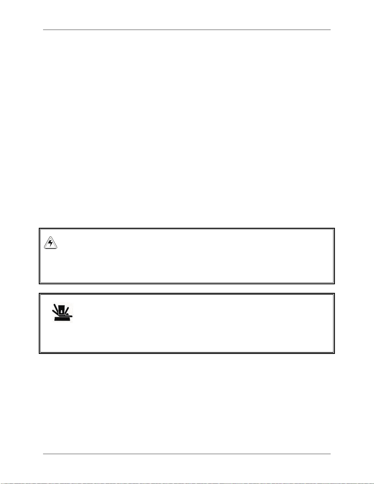
WARNING!
Do not attempt to lift the Excella E-24/24R by yourself. Always ask for
assistance or use a lifter or other suitable equipment when raising or
handling the unit.
CRUSH WARNING!
It is preferable to lift the Excella E-24/24R from the sides of the unit,
but if you lift it from the front and back, be sure to use the finger holes
in the back lip (toward the bottom of the unit). If these finger holes are
not used, the back lip can pinch fingers and hands.
Upon unpacking the unit, inspect it carefully for any damage that may have occurred
during transit. Report any apparent damage to the carrier and to your sales
representative. Save the crate and packing materials.
T
NOTE:
Use of the Excella E-24/24R Shakers requires a platform, which is a separate
item. See the Available Platforms list in Section 9.1.1.
Excella E-24/24R Incubator Shakers M1352-0050 Operating Manual
Page 9

9
2.4 Out of Box Concerns
If any part of your order was damaged during shipping, is missing pieces, or fails to
operate properly, please contact your sales representative and also fill out Customer
Satisfaction Form 6300, included with your equipment, and return it by fax.
2.5 Warranty Registration
Please complete and return your warranty card or register electronically at our Website:
www.nbsc.com
New Brunswick Operating Manual
Page 10
10
33
3.1 Physical Location
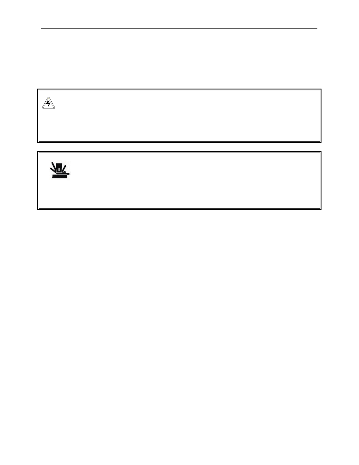
WARNING!
Do not attempt to lift the Excella E-24/24R by yourself. Always ask for
assistance or use a lifter or other suitable equipment when raising or
handling the unit.
CRUSH WARNING!
It is preferable to lift the Excella E-24/24R from the sides of the unit,
but if you lift it from the front and back, be sure to use the finger holes
in the back lip (toward the bottom of the unit). If these finger holes are
not used, the back lip can pinch fingers and hands.
The surface where you place the E-24/24R should be smooth, level and sturdy, and must
be able to accommodate 200 pounds.
P
RREEPPAARRIINNGG TTHHEE
P
L
OOCCAATTIIOON
L
N
3.2 Environment
The shaker is designed to operate optimally in the following ambient conditions:
10º to 35°C
20 to 80% Relative Humidity (non-condensing)
3.3 Electrical Requirements
The E-24/24R can be equipped to run on:
100 Volts, 50/60 Hz, 1500 VA maximum
120 Volts, 60 Hz, 1500 VA maximum
230 Volts, 50 Hz, 1500 VA maximum
In all cases, voltage variations must not exceed ±10%.
Excella E-24/24R Incubator Shakers M1352-0050 Operating Manual
Page 11
11
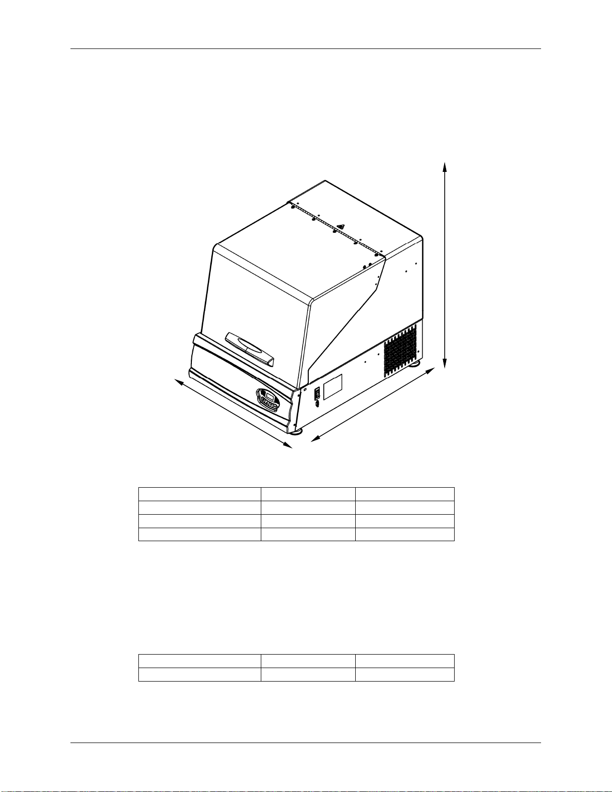
3.4 Space Requirements
It is essential that the shaker be situated in an area where there is sufficient space for the
unit and its service lines (see Figure 1).
Figure 1: Space Requirements
Allow 42 inches of
height to provide
clearance (for
opening the lid)
Allow 27 inches
of width
to provide clearance
Allow 33 inches of depth
to provide clearance
The dimensions of the Excella E-24/24R are:
Width
Depth
Height
Height with lid open
22 inches 55.8 cm
30 inches 76.2 cm
24 1/16 inches 61.1 cm
40½ inches 101.9 cm
NOTE:
Be sure to allow at least three inches (7.6 cm) around shaker for ventilation,
access to power cord (rear panel), and access to power switch and RS-232
port (right side).
The effective surface area required for operation is:
Width
Depth
24 inches 61 cm
30 inches 76.2 cm
New Brunswick Operating Manual
Page 12

12
4.1 Installation of Platform
44
I
NNSSTTAALLLLAATTIIOON
I
NOTE:
There are two small plastic straps that hold the bearing housing in place for
shipping. The straps must be removed from the unit.
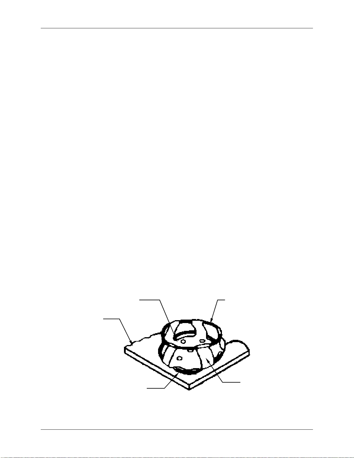
Prior to use, a platform must be installed on the unit. The unit is shipped with four
Allen head PLATFORM SCREWS installed in the SUBPLATFORM of the BEARING
HOUSING
installed:
. These screws must be removed and set aside for use before a platform can be
Figure 2: Platform Screw Locations
N
SUBPLATFORM
1. Using the 7/32-inch hex wrench provided, remove the four Allen head platform
screws from the subplatform. Set them aside.
2. Place the selected
platform with the platform screw locations in the subplatform.
3. Insert the four Allen head platform screws previously removed and set aside. Tighten
them with the 7/32-inch hex wrench provided to secure the platform.
Excella E-24/24R Incubator Shakers M1352-0050 Operating Manual
PLATFORM on the subplatform. Align the mounting holes of the
Page 13
13
4.2 Flask Clamp Installation
Flask clamps purchased for use with universal platforms (see Section 9.1.1) require
installation. Clamps are installed by securing the base of the clamp to the platform with
the correct type and number of screws. All clamps are shipped complete with hardware.
NOTE:
The Excella E-24 and E-24R platforms require 10-24 x 5/16-inch screws,
which are the smaller Phillips head screws supplied, to fasten flask clamps.
Clamps for 2- and 2.8-liter flasks are shipped with an additional girdle to keep the flasks
in place. The girdle is an assembly of springs and sections of rubber tubing. One girdle
is already in place on the clamp, the other is packed separately. To install these double
girdle clamps:
1. Place the clamp on the platform, aligning its mounting holes with holes on the
platform. Secure the clamp in place using the flat Phillips head screws provided
(#S2116-3051, 10-24 x 5/16-inch). Use Figure 3b to help you identify the proper
screws, as three different types of screws are shipped with the clamps.
2. With the first girdle in place, as delivered, on the upper part of the clamp body (see
Figure 3a), insert an empty flask into the clamp.
3. After making sure the sections of tubing are located between the clamp legs, roll the
first girdle down the legs of the clamp as far as it can go. The tubing sections will
rest against the platform, and the springs will be under the clamp base.
4. Place the second girdle around the upper portion of clamp body (just as the first
girdle was initially). Make sure that its spring sections rest against the clamp legs,
while its rubber tubing sections sit against the flask, in between the clamp legs.
Figure 3a: Double Girdle Clamp Installation
UPPER GIRDLE
WITH GIRDLE
TUBES
PLATFORM
CLAMP
MOUNTING
HOLES (5)
LOWER
GIRDLE WITH
GIRDLE TUBES
CLAMP BODY
(LEGS AND BASE)
New Brunswick Operating Manual
Page 14
14
Figure 3b: Clamp Fastener
NOTE:
The upper girdle secures the flask within the clamp, and the bottom girdle
keeps the flask from spinning.
New Brunswick flask clamps are used on a variety of shaker platforms. Flat head
screws of different lengths and thread pitch are used to secure the clamp. With
reference to Figure 3b above, select the appropriate screws and set the others aside.
NOTE:
One-liter and larger flask clamps are fastened with 5 screws.
4.3 Electrical Connections
CAUTION!
Before making electrical connections, be sure to check the following:
1. If you have not already done so, check that the voltage and frequency of your unit are
compatible with your electric supply.
2. Remove the caution label from the rear of the unit.
3. Set the circuit breaker on the right side of the unit to the OFF position.
ONLY THEN:
4. Plug the power cord into a grounded electrical outlet.
CAUTION!
A grounded electrical outlet is necessary for the safe operation of this
instrument.
Excella E-24/24R Incubator Shakers M1352-0050 Operating Manual
Page 15
15
5.1 Control Panel
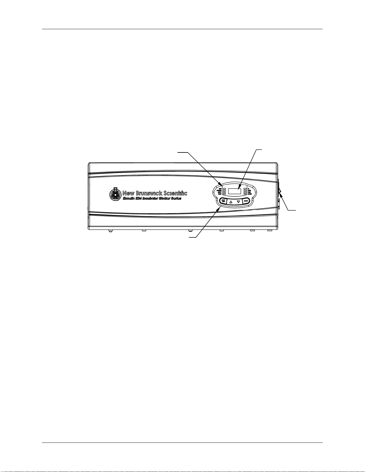
The front panel (see Figure 4) of the Excella E-24/24R shakers provides easy access to
the control panel, which consists of the keypad, display and indicator lights. The ON/OFF
switch is conveniently located on the right side of the unit, as you face the controls.
Figure 4: Control Panel
INDICATORS (see Sections 5.1.4 & 5.1.5)
55
F
EEAATTUURREES
F
LED DISPLAY
(see Section 5.1.3 )
S
ON/OFF
SWITCH
KEYPAD (see Sections 5.1.1 & 5.1.2)
5.1.1 Keypad
The keypad (see close-up in Figure 4a on the following page) is the operator’s
command center for the shaker. In one convenient location are grouped the user
interface keys, the LED display, the status indicator lights and the function
indicator lights.
New Brunswick Operating Manual
Page 16

16
INDICATORS
STATUS
Figure 4a: Keypad
LED
DISPLAY
FUNCTION
INDICATORS
USER INTERFACE
KEYS
5.1.2 User Interface Keys
START/STOP
This key is used to start or stop the shaker. It will
also activate or stop the timer when a timed run is
desired.
SELECT
This key is used to change the displayed parameter.
(UP), (DOWN)
These keys are used to adjust the setpoint of a
displayed parameter up or down. They also allow
the user to enter the
changes.
5.1.3 LED Display
The digital display on the control panel is a three-digit LED DISPLAY. During
normal shaker operation, the display will indicate:
Shaker status (On/Off)
Shaking speed
Chamber temperature
Setpoints
Hours remaining (in a timed run)
Lid open (“LID”)
SET MODE for setpoint
Excella E-24/24R Incubator Shakers M1352-0050 Operating Manual
Page 17

17
5.1.4 Status Indicators
Four status indicator lights are located to the left of the LED DISPLAY. They are:
SET
Indicates that the shaker is in the
SET MODE,
when setpoints are being displayed and can be
altered. This is activated by the
SELECT key
or by pressing the (UP) or (DOWN) KEY.
POWER
Illuminates and blinks during power up or if
power is interrupted during a run. Press the
SELECT key and change to another function to
turn off this indicator.
HEAT
Illuminates to indicate that the heater is on.
TIME
Indicates that the timer is in operation. The
shaker can be programmed to run for a preset
time from 0.1 to 99.9 hours. The timer can be
disengaged without stopping an ongoing run.
5.1.5 Function Indicators
Four function indicator lights are located to the right of the LED DISPLAY. They indicate
the current parameter(s) being displayed:
C
Interior chamber temperature. Can be set from
4°C to 60°C, when in SET MODE, using the
(UP) or (DOWN) KEY. It indexes at 0.1°C
increments unless the key is pressed for 4
seconds, after which it indexes more rapidly.
RPM
Revolutions per minute. When in SET MODE,
use the (UP) or (DOWN) KEY to change the
speed. It indexes at 1 RPM increments unless
the key is pressed for 4 seconds, after which it
indexes more rapidly.
New Brunswick Operating Manual
Page 18

18
HRS
Time remaining in a timed run. Can be set
from 0.1 to 99.9 hours, in 0.1 increments or, if
the (UP) or (DOWN) KEY is pressed for 4
seconds, the time indexes more rapidly.
The countdown begins when the START/STOP
key is pressed. If the START/STOP key is
pressed, the shaking stops (but temperature is
maintained) and the timer pauses until the
START/STOP key is pressed again.
When a timed run ends, the HRS indicator will
blink. Press the SELECT key and change to
another function to turn off this indicator.
MUTE
This feature is controlled by the SELECT key.
When activated, the audible alarm is muted,
and remains so until is is reactivated. If MUTE
is activated when the shaker is turned off using
the ON/OFF switch, it will remain engaged
when the machine is powered up again. To
activate (or deactivate) the MUTE function,
press the SELECT key until the MUTE indicator
illuminates; press the (UP) or (DOWN) KEY
to display ON or OFF, as desired; then press
SELECT.
Excella E-24/24R Incubator Shakers M1352-0050 Operating Manual
Page 19

19
6.1 Electrical Connections
Before making electrical connections, verify that the power source voltage matches the
voltage on the ELECTRICAL SPECIFICATION PLATE and that the ON/OFF SWITCH is on the
OFF position. The ELECTRICAL SPECIFICATION PLATE is located on the rear panel of the
unit near the
CONNECTOR
end to a suitable, grounded receptacle.
6.2 Starting the Shaker
To initially start the shaker, close the lid and turn the ON/OFF SWITCH on the right side
panel of shaker to the ON position. During start-up, the LED DISPLAY will indicate the
model of your shaker. When the shaker begins to operate, the LED DISPLAY will track the
speed as it accelerates to the last entered setpoint. The shaking action may be started or
stopped by pressing the START/STOP KEY on the KEYPAD.
POWER CONNECTOR. Connect the POWER CORD to the POWER
(Universal Voltage Input Module) on the rear panel, then connect the other
Figure 5: ON/OFF Switch Location
66
O
PPEERRAATTIIOON
O
N
LID
HANDLE
KEYPAD
ON/OFF SWITCH
NOTE:
The shaker will not operate if the lid is open.
New Brunswick Operating Manual
Page 20

20
6.3 Continuous (Untimed) Run
1. Press SELECT until the RPM INDICATOR is illuminated.
2. If the display indicates that the shaker is OFF, press the START/STOP KEY.
3. Press either the
(UP) or (DOWN) KEY to enter SET MODE (the SET INDICATOR will
illuminate).
4. Set the speed by using the
(UP) or (DOWN) KEY until the desired setpoint is
displayed. Continued pressure the (UP) or (DOWN) KEY will cause the setting to
change more rapidly.
NOTE:
The setpoint may be changed during a run without stopping the shaker by
following steps 2-4 above. During speed changes, a visual alarm (flashing
RPM INDICATOR) will flash and an audible alarm will sound until the speed
returns to within 5 rpm of the setpoint.
6.4 Checking Any Setpoint
1. Press SELECT until the desired indicator is illuminated.
2. Briefly press either the (UP) or (DOWN) KEY to enter the SET MODE and display
the current setpoint.
CAUTION!
Holding the the (UP) or (DOWN) KEY for more than 0.5 seconds causes the
speed setpoint to change. Should this occur, resetting will be necessary.
6.5 Timed Functions
The shaker may be programmed to automatically stop after a preset time period of 0.1 to
99.9 hours. There must be power to the shaker in order to set the timer, although a timed
run can be initiated while the unit is either stopped or operating.
To set the timer:
1. Press the SELECT KEY until the HRS INDICATOR is illuminated.
2. Press either the (UP) or (DOWN) KEY to enter the SET MODE and set the desired
run time, between 0.1 and 99.9 hours.
If the shaker is stopped, skip to Step 5 below. If the shaker is already running:
3. Press the START/STOP KEY. The shaker will stop and the display will read OFF.
Excella E-24/24R Incubator Shakers M1352-0050 Operating Manual
Page 21

21
4. Press the START/STOP KEY again; the TIME INDICATOR will light and the shaker will
start the timed run.
If the shaker is stopped:
5. Press the START/STOP KEY. The shaker will start in untimed mode.
6. Press the START/STOP KEY again. The shaker will stop and the display will read
OFF.
7. Press the START/STOP KEY a third time; the TIME INDICATOR will light and the
shaker will start the timed run.
To disable the visual alarm (flashing TIME INDICATOR), press the SELECT KEY and
change to any other function.
To cancel the timer without stopping the shaker:
Repeat steps 1 and 2 above, then immediately press the START/STOP KEY. The TIME
INDICATOR
will cease to flash and the display will read OFF.
6.6 Alarm Functions
In addition to the visual alarm mentioned above, the Excella E-24/24R shakers have an
audible alarm that is activated at predetermined times, as explained in Section 1
(Overview). It can be deactivated by using the MUTE function:
1. Press the SELECT key until the MUTE indicator illuminates.
2. Press the (UP) or (DOWN) KEY to display ON, then press the SELECT KEY.
To reactivate the audible alarm:
1. Press the
2. Press the
SELECT key until the MUTE indicator illuminates.
(UP) or (DOWN) KEY to display OFF, then press the SELECT KEY.
6.7 Temperature Setpoint
Press the SELECT KEY until the function C INDICATOR illuminates. The temperature can
be set from 5C above ambient temperature to 60C (non-refrigerated units) or from 4C
to 60C (refrigerated units). Increasing or decreasing the setpoint is accomplished with
(UP) or (DOWN) KEY.
the
During operation, if the temperature of the chamber is more than 1.0C higher or lower
than the temperature setpoint, an alarm is triggered. This alarm consists of a flashing C
New Brunswick Operating Manual
Page 22

22
INDICATOR and audible beep. The alarm will automatically deactivate as the unit
achieves the set temperature.
6.8 Temperature Offset Calibration
The temperature probe and the temperature controller are calibrated together at the
factory. The temperature probe measures the temperature of the air at the probe’s
location, near the heat exchanger return vent. The controller uses the probe input to
adjust air temperature, up or down, to match the temperature setpoint.
Depending on various conditions within the chamber, such as flask placement and size,
the heat produced by growing organisms, heat losses due to liquid evaporation from
flasks, etc., the display temperature may differ from temperatures within the flasks
themselves.
If you wish to have the temperature display (“Indicated Temperature”) match the
temperature at a given point, or match the average of a series of points within the
chamber (“Actual Temperature”), proceed as follows:
1. Let the unit equilibrate at or near the desired temperature. Record the Indicated
Temperature.
2. Record the Actual Temperature.
3. Calculate the temperature correction value: Actual Temperature – Indicated
Temperature = Temperature Correction Value.
4. Press the SELECT KEY until the function C INDICATOR illuminates.
5. Simultaneously press the (UP) and (DOWN) KEYS. The display will indicate CAL.
6. Using the (UP) or (DOWN) KEY, enter the Temperature Correction Value
calculated in Step 3 above.
7. Simultaneously press the (UP) and (DOWN) KEYS to save the Temperature
Correction Value to memory.
NOTE:
°C light will pulse rapidly to indicate it is not operating in the factory
The
default mode.
To return to the factory calibration:
1. Press the
2. Simultaneously press the (UP) and (DOWN) KEYS. The display will indicate CAL.
3. Using the
4. Simultaneously press the
INDICATOR will stop.
Excella E-24/24R Incubator Shakers M1352-0050 Operating Manual
SELECT KEY until the function C INDICATOR illuminates.
(UP) or (DOWN) KEY, set the Temperature Correction Value to zero.
(UP) and (DOWN) KEYS. The rapid pulsing of the C
Page 23

23
6.9 Power Failure
In the event of a power failure, the Excella E-24/24R shakers are equipped with an
automatic restart function.
If the shaker was in operation prior to the power interruption, when power is restored the
shaker will begin to operate at its last entered setpoint. The LED DISPLAY will flash and
the audible alarm will sound, indicating that a power failure has occurred. Press any key
to cease the flashing in the display and the audible alarm.
6.10 Speed Calibration
To calibrate the shaking speed:
1. Set the shaker to a speed that can easily be measured. If you are using a strobe,
minimum speed should be 250 RPM.
2. Compare the reading on the display to the measured reading.
If an adjustment is needed:
1. Press the SELECT KEY until the RPM indicator light illuminates.
2. Press the (UP) and (DOWN) KEYS simultaneously. The display will indicate CAL.
3. Press either the (UP) or (DOWN) KEY to change the displayed value to match the
measured speed.
4. Press the (UP) and (DOWN) KEYS simultaneously to save the adjustment.
5. Turn unit OFF using the power switch, then turn it back ON.
New Brunswick Operating Manual
Page 24

24
WARNING!
When cleaning the unit, always turn off the shaker and disconnect the
power cord from the power supply.
7.1 Routine Maintenance
No routine maintenance schedule is required for the Excella E-24 and E-24R.
To ensure that your shaker retains its attractive appearance, an occasional cleaning, using
a cloth with conventional household (non-abrasive) cleaner is recommended (see Section
7.2 below for more details).
We also suggest that the area around the shaker be vacuumed or swept to remove dust
and other debris, ensuring proper air flow in and around the shaker.
77
M
AAIINNTTEENNAANNCCE
M
E
7.2 Cleaning External & Internal Surfaces
The unit may be cleaned using a damp cloth or any standard household or laboratory
cleaner to wipe down its outer surfaces. Do not use abrasive or corrosive compounds to
clean this instrument, as they may damage the unit and void the warranty.
If Biohazard decontamination is required, see Section 7.3 below.
7.3 Biohazard Decontamination
It is the responsibility of the user to carry out appropriate decontamination
procedures if hazardous material is spilled on or inside the equipment. Before
using any cleaning or decontamination method other than those suggested by the
manufacturer, users should check with Eppendorf that the proposed method would
not damage the equipment.
Commercially available household bleach solutions, when diluted at a 1:10 ratio, are
effective in routine decontamination of the instrument. The method for decontaminating
a spill depends upon the nature of the spill.
Excella E-24/24R Incubator Shakers M1352-0050 Operating Manual
Page 25

25
Spills involving fresh cultures or samples known to have low concentrations of biomass
should be flooded with decontamination solution and soaked for 5 minutes before
cleanup. Spills involving samples with high concentrations of biomass, or involving
organic matter, or occurring in areas warmer than room ambient temperature, should be
exposed to decontamination solution for at least one hour before cleanup.
WARNING!
Personnel involved in the cleanup of any spill should wear gloves, safety
glasses, and a laboratory coat or gown during the cleanup process.
Respiratory protection should be considered for spills where aerosolization
is suspected.
New Brunswick Operating Manual
Page 26

26
8.1 Troubleshooting
If any problems occur with your shaker, do not attempt to perform any service on the unit
other than specified in this manual. Unauthorized servicing may void the warranty.
Please contact your local Eppendorf Customer Service Department
In any correspondence with Eppendorf, please refer to the model number and serial
number of your unit. This information is on the electrical specification plate, located on
the rear panel of the unit, above the power connector.
There are some problems, however, that you can investigate and correct yourself. Refer
to the following Troubleshooting Guide:
Symptom(s) Probable Cause(s) & Solution(s)
Shaker does not run.
Shaker runs slowly
and/or no speed
indication.
Shaker does not run at
set speed.
Power cord is not plugged in and/or power switch is off: plug in
power cord (to working electric outlet), and turn on power
switch.
Lid is open and “LID” is indicated on display: close lid firmly.
On/Off switch is not working: call for service.
If you recently replaced a fuse, it may not have been seated
properly: remove and reinstall the fuse carefully.
Defective main board: call for service
Defective display controller board: call for service.
Jammed shaking mechanism: call for service
Defective motor: call for service
Drive belt out of alignment or worn: call for service.
Incorrect speed calibration: recalibrate shaking speed (see
Section 6.10).
Defective main board: call for service.
Defective motor: call for service.
Drive belt is out of alignment or worn: call for service.
Shaker is overloaded and/or you are using baffled flasks:
remove some contents & balance load.
Defective motor: call for service.
Drive belt out of alignment or worn: call for service.
Load out of balance: unload all contents, then reload. Operating noise
Loose component(s) in platform, subplatform and/or drive
assembly: call for service.
...continued...
88
S
EERRVVIICCE
S
E
Excella E-24/24R Incubator Shakers M1352-0050 Operating Manual
Page 27
27
Symptom(s) Probable Cause(s) & Solution(s)
Incubator does not
reach set temperature.
indication.
Heater fuse blown: replace.
Compressor fuse blown: replace.
Compressor over-pressure switch activated: call for service.
Ambient temperature too high or too low: cool or heat the
room as needed.
Defective heater: call for service.
Defective refrigeration system: call for service.
Incorrect temperature indication (see below).
Defective RTD assembly: call for service. Incorrect temperature
Defective main board: call for service.
8.2 Product Returns
Should you need to return your Excella E-24/24R to Eppendorf for any reason, first
contact Customer Service to obtain a Returned Material Authorization (RMA) number.
This number must appear on the outside of the shipping container, otherwise Eppendorf
Receiving will refuse to accept the shipment.
In addition, you must also certify that the instrument being returned has been thoroughly
cleaned and decontaminated. A form for this purpose is provided in Section 12 of this
manual; it can also be downloaded from our website (www.nbsc.com). A copy of this
completed Return Authorization and Decontamination Certificate must be attached to the
outside of the container, with a second copy packed inside with the instrument.
8.3 Opening the Service Compartment
WARNING!
Before opening the Service Compartment, always turn off the shaker and
disconnect the power cord from the power supply.
The Service Compartment contains the shaker’s electronic and temperature control
components. Normally, this compartment should be accessed by authorized service
technicians only. You may, from time to time, need to remove the access panel in order
to replace fuses (see Section 8.4 below).
New Brunswick Operating Manual
Page 28

28
8.4 Fuse Replacement
WARNING!
When replacing fuses, always turn off the shaker and disconnect the power
cord from the power supply.
The user can replace one fuse on the Excella E-24 and two fuses on the E-24R. Fuses are
located behind the front bezel panel, on the PC board. To access the fuses:
1. Turn the power off and unplug the shaker. Open the cover of the shaker.
2. Remove the four fasteners that hold the front panel in place, setting them aside for
reuse.
3. Open the front panel, allowing it to lay flat.
4. The fuses are located on the PC board (see Figures 6,7a & 7b), which you will find
on the right side of the base weldment.
Figure 6: Accessing Fuses
FRONT PANEL REMOVED
(but not shown)
PC BOARD
(see Figures 7a & 7b)
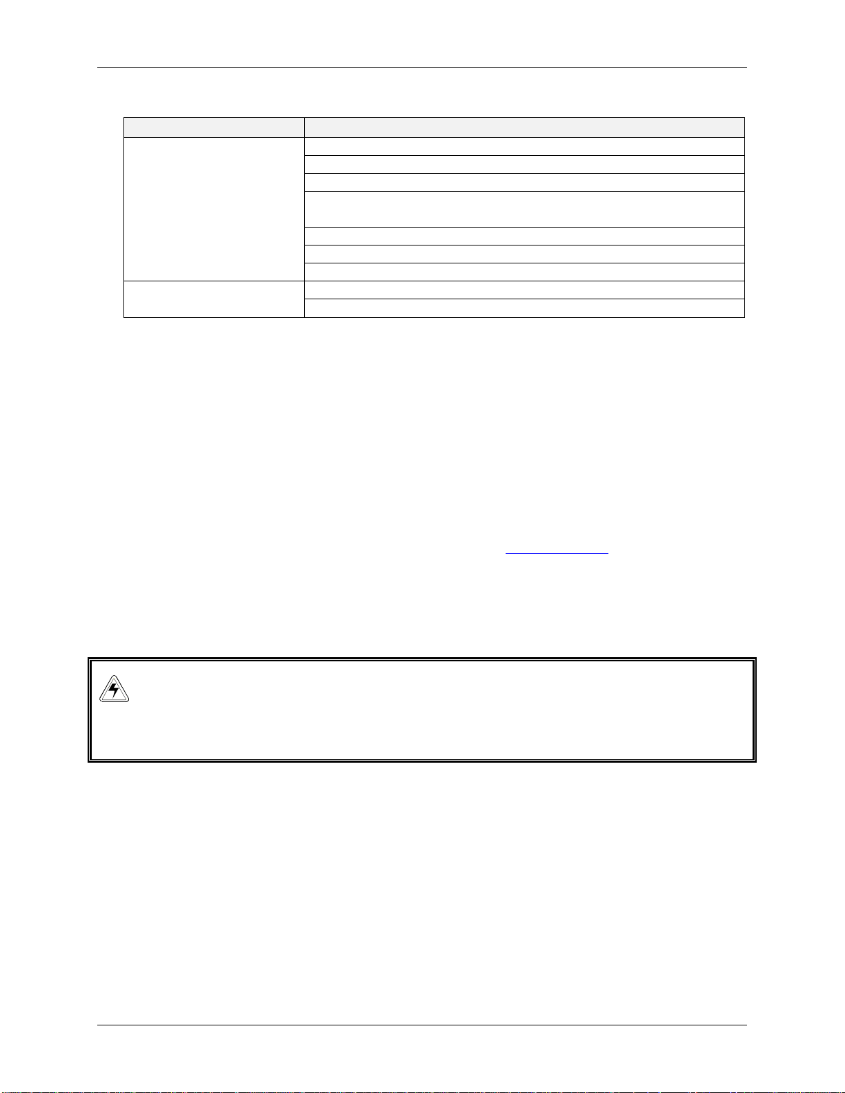
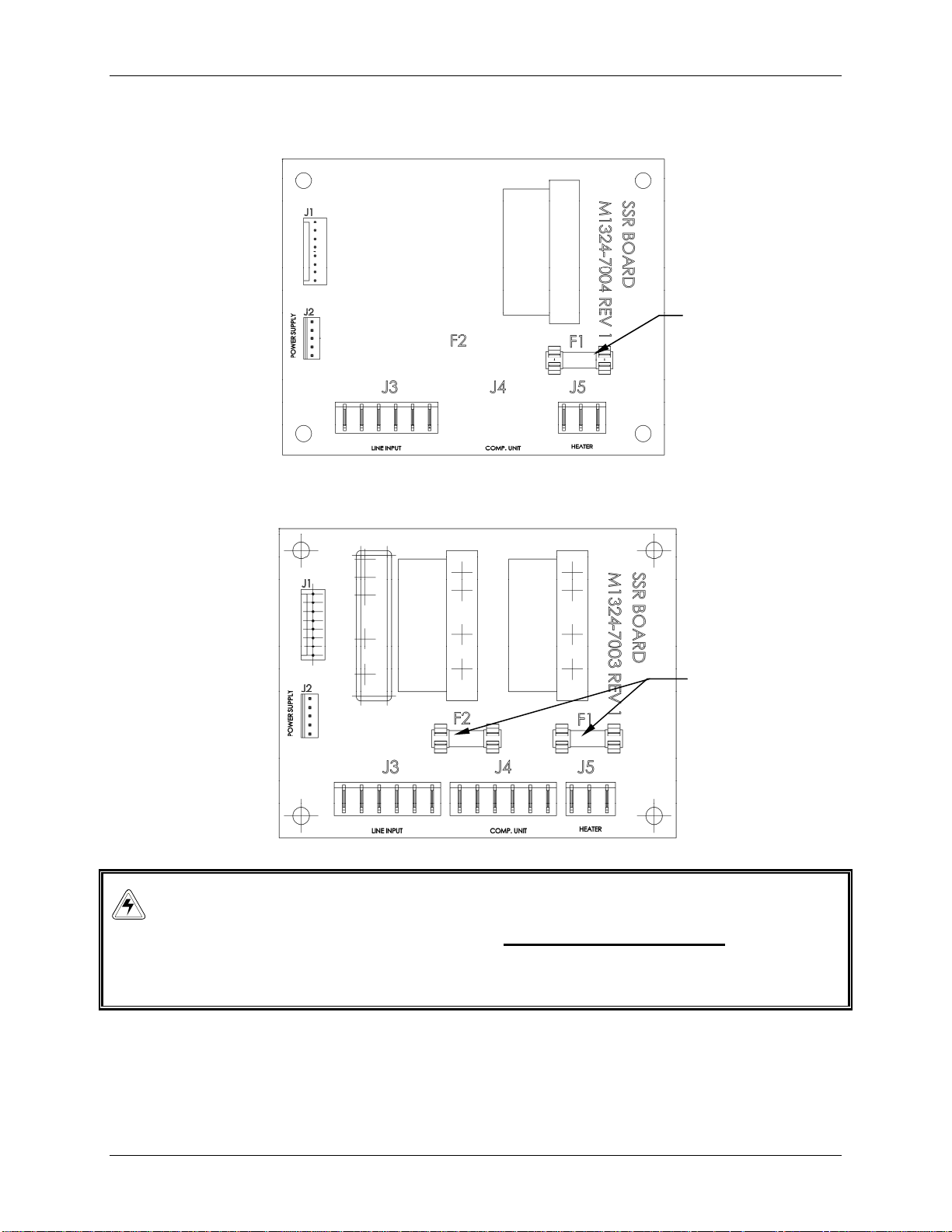
5. Fuses are numbered (see Table 1); access the fuse you wish to replace by using a coin
or a blade screwdriver to turn and release the spring-loaded cap.
6. Replace the fuse with a new one of the same type and rating (see Table 1):
Table 1: Fuses
Fuse Holder
Number
F1 Heater 8.0 A
F2 Refrigeration (E-24R only)
Function Type Rating
Slo Blo
®
8A
8.0 A
Excella E-24/24R Incubator Shakers M1352-0050 Operating Manual
Page 29
29
Figure 7a: Fuse Replacement (Excella E-24)
FUSE
Figure 7b: Fuse Replacement (Excella E-24R)
FUSES
WARNING!
The following procedures are provided for your information only.
Do not attempt to perform these service interventions yourself unless you
are an authorized service technician.
New Brunswick Operating Manual
Page 30

30
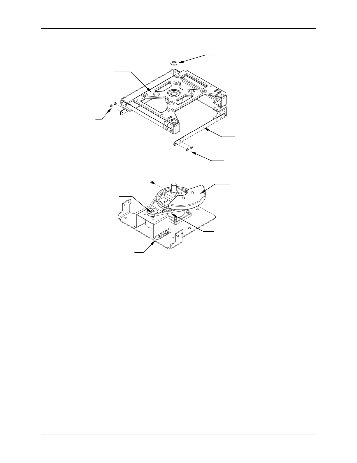
8.5 Belt Replacement or Adjustment
To gain access to the drive belt, your service technician will follow these steps with
reference to Figure 8:
WARNING!
Always keep fingers clear of the drive belt and pulley.
1. Set the ON/OFF power switch to OFF.
2. Disconnect the power cord from the electrical outlet.
3. Open the lid.
4. Using an Allen wrench, remove the four Allen head screws that hold the platform to
the bearing housing. Set the platform and its mounting screws aside for reuse.
5. Remove the E-ring that holds the upper bearing housing to the shaft.
6. Remove the four nuts (two on either side) from the bearing housing mounting plate.
These nuts hold the flexure arms in place.
7. Slide the upper bearing housing off the shaft, and set it aside.
8. Use the hex wrench to loosen the four hex nuts on the motor mounting bracket.
9. Gently slide the motor mounting bracket toward the righthand side of the shaker.
This loosens the drive belt from the motor pulley and the large counterweighted
pulley. Moving the motor mounting bracket forward will cause the belt to fall from
both belt tracks.
10. Remove the old belt.
11. With one hand, place the new belt around the motor pulley, and with the other hand
guide the belt around the large counterweighted pulley.
12. Move the motor mounting bracket back, until there is a slight resistance.
13. Verify that the drive belt has a slight pressure near the center. The recommended
deflection is 3/8 inch (9.5 mm).
Excella E-24/24R Incubator Shakers M1352-0050 Operating Manual
Page 31
31
Figure 8: Drive Belt Replacement
E-RING
UPPER
BEARING
HOUSING
FLEXURE
ARM NUTS
FLEXURE ARM
FLEXURE ARM NUTS
COUNTERWEIGHTED
MOTOR
PULLEY
PULLEY
DRIVE BELT
MOTOR MOUNTING
BRACKET
14. Use the hex wrench to tighten the four hex nuts on the motor mounting bracket.
15. Reinstall the upper bearing housing on the shaft.
16. Reattach the flexure arms to the bearing housing mounting plate with the four nuts
previously removed.
17. Reattach the E-ring to the shaft.
18. Reinstall the platform on the bearing housing with the four Allen head screws
previously removed.
19. Close the shaker lid.
20. Reconnect the power cord to the electrical outlet.
New Brunswick Operating Manual
Page 32

32
8.6 Replacement Parts
We recommend that you keep on hand one spare motor drive belt and two (each)
replacement fuses. Eppendorf offers a spare parts kit that contains commonly needed
replacement parts for your Excella E-24/24R (see Table 2 below).
Table 2: Spare Parts Kit M1352-6000
V-Belt 1
Gas springs 2
Fuse, 8-amp 4
Description Quantity
Excella E-24/24R Incubator Shakers M1352-0050 Operating Manual
Page 33

33
99
When ordering accessories, you may be asked to provide the model number and serial number of
your shaker. This information is on the electrical specification plate, located on the rear panel of
the unit.
9.1.1 Platforms
Table 3: Available Platforms
Description Capacity Part No.
Universal Platform see Table 4 M1250-9902
125 mL Erlenmeyer flask Dedicated Platform* 34 M1194-9904
250 mL Erlenmeyer flask Dedicated Platform* 25 M1194-9905
500 mL Erlenmeyer flask Dedicated Platform* 16 M1194-9906
1L Erlenmeyer flask Dedicated Platform* 9 M1194-9907
2L Erlenmeyer flask Dedicated Platform* 5 M1194-9908
2.8L Fernbach flask Dedicated Platform* 4 M1194-9932
Utility carrier with cushioned crossbars -- M1194-9909
Utility tray with non-skid rubber surface -- M1194-9910
Sticky pad platform -- M1250-9903
*dedicated platforms include flask clamps
Should you decide in favor of the Universal Platform, following is a list of that
particular platform’s flask capacity, according to flask size:
Table 4: Universal Platform Flask Capacities
Flask Type Capacity*
50 ml Erlenmeyer Flasks 45
125 ml Erlenmeyer Flasks 21
250 ml Erlenmeyer Flasks 18
500 ml Erlenmeyer Flasks 14
1 L Erlenmeyer Flasks 8
2 L Erlenmeyer Flasks 5
2.8 L Fernbach Flasks 4
*Clamps for Universal Platform are sold separately.
A
CCCCEESSSSOORRIIEES
A
S
9.1.2 Flask Clamps for Universal Platforms
The following clamps, according to flask size, are available for use with the
Universal Platform:
New Brunswick Operating Manual
Page 34

34
Table 5: Flask Clamps
Clamp Size Part Number
10 ml Erlenmeyer Flask ACE-10S
25 ml Erlenmeyer Flask M1190-9004
50 ml Erlenmeyer Flask M1190-9000
125 ml Erlenmeyer Flask M1190-9001
250 ml Erlenmeyer Flask M1190-9002
500 ml Erlenmeyer Flask M1190-9003
1 L Erlenmeyer Flask ACE-1000S
2 L Erlenmeyer Flask ACE-2000S
2.8 L Fernbach Flask ACSB-2800S
9.1.3 Replacement Clamp Hardware Kits
New Brunswick flask clamps come complete with mounting screws. Additional
screws are available separately in packs of 25 (see Section 8.6).
9.1.4 Test Tube Racks & Other Accessories
Table 6: Racks & Trays
Accessory Description Part
Adjustable angle Test Tube
Rack for tubes 8 – 11 mm
diameter
Adjustable angle Test Tube
Rack for tubes 12 - 15 mm
diameter
Adjustable angle Test Tube
Rack for tubes 15 –18 mm
diameter
Adjustable angle Test Tube
Rack for tubes 18 – 21 mm
diameter
Adjustable angle Test Tube
Rack for tubes 22 – 26 mm
diameter
Adjustable angle Test Tube
Rack for tubes 26 - 30 mm
diameter
Microplate holder rack
(stacked)
Microplate holder rack
(single layer)
80 tube capacity M1289-0100 4
60 tube capacity M1289-0010 5
48 tube capacity M1289-0001 5
60 tube capacity M1289-0200 4
44 tube capacity M1289-0020 5
34 tube capacity M1289-0002 5
42 tube capacity M1289-0300 4
31 tube capacity M1289-0030 5
24 tube capacity M1289-0003 5
30 tube capacity M1289-0400 4
23 tube capacity M1289-0040 5
18 tube capacity M1289-0004 5
22 tube capacity M1289-0500 4
16 tube capacity M1289-0050 5
13 tube capacity M1289-0005 5
20 tube capacity M1289-0600 4
16 tube capacity M1289-0060 5
12 tube capacity M1289-0006 5
3 deep well or 9 standard M1289-0700 8
5 deep well or standard TTR-221 2
...continued...
Number
Platform
Capacity
Excella E-24/24R Incubator Shakers M1352-0050 Operating Manual
Page 35

35
Accessory Description Part
Number
Angled Test Tube Rack Holder* for user-supplied test tube
racks that are 4-5 in. (10-13 mm) wide and up to 15 in.
(38 mm) long.
Angled Test Tube Rack Spacer Bar* for use with TTR-210
to accommodate test tubes racks that are less than 5 in.
(13 mm) wide.
* Universal Platform Required
TTR-210
TTR-215
Platform
Capacity
2
NA
New Brunswick Operating Manual
Page 36

36
10.1 Schematics
Figure 9: Control Schematics (overview)
CB001 CB001
15 AMP
15 AMP
N
G
L
RED
BLACK
WHITE
YELLOW
RED
BLACK
WHITE
YELLOW
RED
BLACK
WHITE
YELLOW
line
THERMAL
THERMAL
THERMAL
M1324-8019
SWITCH
M1335-8018
SWITCH
M1335-8018
SWITCH
Filter
BLACK
L
2222
1212
LF1
load
M1324-8002
WHITE
L
N
TB002
TB002
TB002
1
J3
N
4
J5
3
1
WHITE
RED
RED
M1352-8003
M1324-8001
WHITE
RED
AC POWER
ENTRY
100-240 VAC 50/60Hz
HEATER 230Vac OPERATION
HEATER 120Vac OPERATION
HEATER 100Vac OPERATION
BLACK
M1299-8010
WHITE
M1299-8009
2121
1111
1100
SSR BOARD
M1324-7004
(REFRIGERATION OPTION)
(M1324-7003)
J4
21 6543
VIOLET
YELLOW
ORANGE
WHITE
BLACK
M1324-8010
DISPLAY BOARD
M1324-7002
1 2 3 4 5
1
J2
3
4123J1765
4321
76561
J2
POWER DISTRIBUTION
DISPLAY DRIVER BOARD
J5
M1352-8001
20 Cond. Ribbon Cable
J4
J2
M1352-8006
BRN
J6
M1324-7001
D
RRAAW
D
PINK
J3
84
WIINNGGSS
M1352-8005
J4
M1352-8004
1
12
2
CN2
11
3
10
M1282-8003
50 Cond. Ribbon Cable
DOOR SW.
E-24; I-24
5
3
CN1
1
POWER SUPPLY
J1
34
M1352-8009
&
T
&
R1 - 7.5 ohm/25W
PINK
BRN
M1352-8005
PINK
BRN
PINK
BRN
M1352-8005
BRN
-MGND
J6BJ6A
J6
J5
CONTROL BOARD
M1324-7000
M1352-8005
PINK
+30V
J7
3
4
5
6
7
J1
8
9
10
1
1
2
3
4
J3
AABBLLEES
T
WHITE
WHITE
PINK
BRN
BLUE
BLUE
M1299-8002
PHASE C
PHASE B
PHASE A
GND
VREF
Temp.
Sensor,RTD
M1195-8001
RS232
10 Cond.
Ribbon Cable
Port
M1299-8020
M1352-8008
SA
SB
SC
S
+
+
FAN1
FAN2
1
2
3
4
MTR
5
M001
6
7
8
(REFRIGERATION OPTION)
COMPRESSOR UNIT
M1352-8011
SEE DRAWING #2 FOR DIFFERENT VOLT OPERATION
TB001
KEY PAD
ALARM OPTION
(I24 ONLY)
NOTE:
For a larger version of this drawing, contact your sales or service
representative.
Excella E-24/24R Incubator Shakers M1352-0050 Operating Manual
Page 37

37
Figure 10a: 230VAC/50 Hz Schematic
230Vac/50Hz OPERATION
POWER
TRANSFORMER
M1324-8015
N
230V
100V
120V
FROM
M1324-7003
RED
ORANGE
BLACK
WHITE
YELLOW
VIOLET
M1352-8002
J4-1
J4-3
J4-5
J4-2
J4-4
J4-6
COND. FAN
OVER PRESSURE
SWITCH
M1324-8016
COMPRESSOR
UNIT
ORANGE
M1352-8007
BLUE
1
2
BLACK
BLACK
BLACK
VIOLET
ORANGE
WHITE
BLACK
M1352-8007
RED
TB001
Figure 10b: 100VAC/60 Hz Schematic
100Vac/60Hz OPERATION
POWER
TRANSFORMER
M1324-8015
N
230V
120V
100V
TB001
M1352-8002
COND. FAN
OVER PRESSURE
SWITCH
M1324-8016
COMPRESSOR
UNIT
ORANGE
M1352-8007
BLUE
1
2
BLACK
BLACK
BLACK
VIOLET
WHITE
ORANGE
M1352-8007
RED
BLACK
M1324-7003
ORANGE
BLACK
RED
WHITE
YELLOW
VIOLET
FROM
J4-3
J4-5
J4-1
J4-2
J4-4
J4-6
New Brunswick Operating Manual
Page 38

38
Figure 10c: 100VAC/50 Hz Schematic
100Vac/50Hz OPERATION
POWER
TRANSFORMER
M1324-8015
N
230V
120V
100V
FROM
M1324-7003
ORANGE
RED
BLACK
WHITE
YELLOW
VIOLET
M1352-8002
COND. FAN
ORANGE
M1352-8007
OVER PRESSURE
SWITCH
M1324-8016
COMPRESSOR
UNIT
BLUE
RED
ORANGE
WHITE
BLACK
BLACK
BLACK
M1352-8007
BLACK
1
VIOLET
2
TB001
J4-3
J4-1
J4-5
J4-2
J4-4
J4-6
Figure 10d: 120VAC/60 Hz Schematic
120Vac/60Hz OPERATION
TB001
COND. FAN
ORANGE
M1352-8007
BLUE
OVER PRESSURE
SWITCH
M1324-8016
COMPRESSOR
UNIT
BLACK
BLACK
M1352-8002
BLACK
VIOLET
M1352-8007
1
2
FROM
M1324-7003
RED
ORANGE
BLACK
WHITE
YELLOW
VIOLET
J4-1
J4-3
J4-5
J4-2
J4-4
J4-6
Excella E-24/24R Incubator Shakers M1352-0050 Operating Manual
Page 39
39
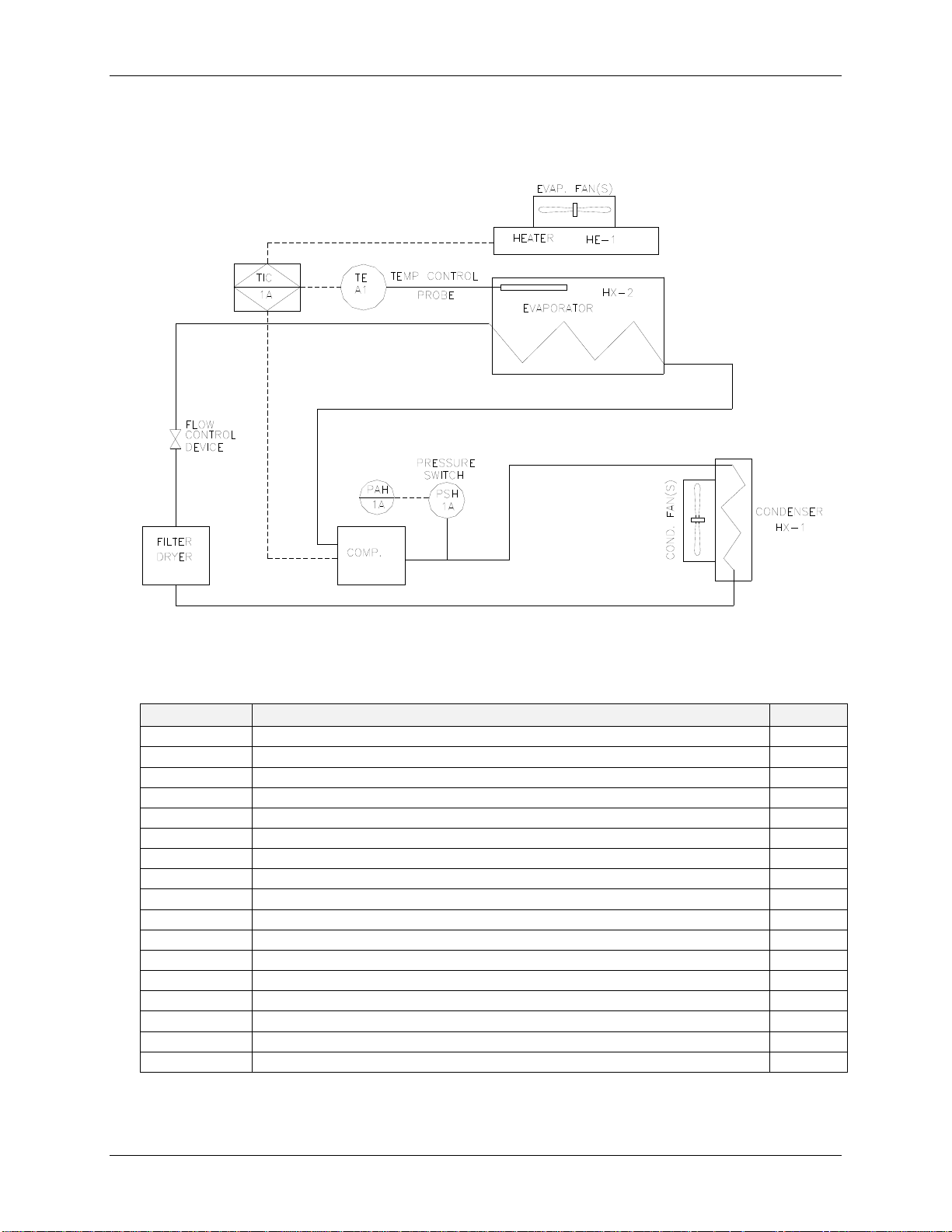
Figure 11: Refrigeration Schematic
10.2 List of Drawings
Figure Description Page
1 Space Requirements 14
2 Platform Screw Locations 15
3a Double Girdle Clamp Installation 16
3b Clamp Fastener 17
4 Control Panel 18
4a Keypad 19
5 ON/OFF Switch Location 22
6 Accessing Fuses 31
7a Fuse Replacement (Excella E-24) 32
7b Fuse Replacement (Excella E-24R) 32
8 Drive Belt Replacement 34
9 Control Schematic 39
10a 230VAC/50 Hz Schematic 40
10b 100VAC/60 Hz Schematic 40
10c 100VAC/50 Hz Schematic 41
10d 120VAC/60Hz Schematic 41
11 Refrigeration Schematic 42
New Brunswick Operating Manual
Page 40

40
10.3 List of Tables
Table Description Page
1 Fuses 31
2 Spare Parts Kit M1352-6000 35
3 Available Platforms 36
4 Universal Platform Flask Capacities 36
5 Flask Clamps 37
6 Racks & Trays 37
Excella E-24/24R Incubator Shakers M1352-0050 Operating Manual
Page 41
41
S
1111
PPEECCIIFFIICCAATTIIOONNS
S
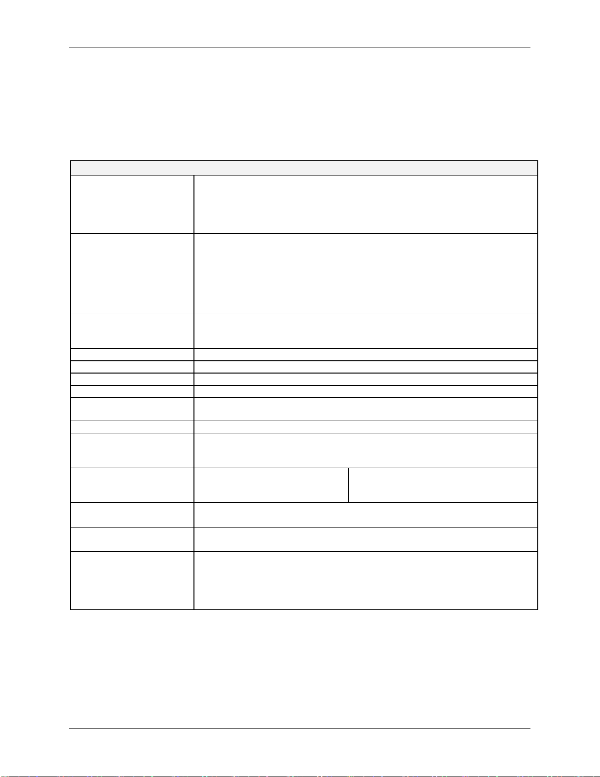
These specifications assume a maximum load of 34 pounds (15.5 kg), including platforms,
clamps, glassware and contents.
Excella E-24 & E-24R Incubator Shaker
SHAKING
Speed
Control Accuracy
Indication
Stroke/Orbit
TEMPERATURE
Range (E-24)
Range (E-24R)
Control Accuracy
Indication
Heater
ALARMS
LED DISPLAY
RS-232
SETPOINT RETENTION
AUTOMATIC RESTART
DRIVE
DRIVE MOTOR
SAFETY
ELECTRICAL
REQUIREMENTS
ETL REGULATORY
STANDARDS
CE REGULATORY
STANDARDS
DIMENSIONS
Width
Depth (Front to Back)
Height
Height with lid open
1
see first NOTE on following page
2
depending on ambient factors, such as relative humidity. Ambient temperature is measured one meter
from the front of the shaker
1
2
2
50-400 rpm
1 rpm
Displayed in 1 rpm increments
¾-inch (1.9 cm)
7ºC above ambient temperature to 60°C
15ºC below ambient temperature (minimum 4ºC) to 60°C
0.1°C at 37°C
Displayed in 0.1°C increments
Long-life, low-watt density resistance-type heater with high temperature
thermostat
Visible and audible warning indication when speed deviates more than 5
rpm or temperature more than 1°C from setpoints, and when timer has
expired. Audible alarm can be muted.
9/16-inch (1.4 cm)
Data logging
All setpoints and operating status are retained in non-volatile memory
Automatic restart after power is restored, indicated by flashing display
UniCentric™ counterbalanced drive with four permanently lubricated ball
bearings
Solid-state brushless DC motor.
Drive Interrupt shuts off power to Shaker when lid opens.
Acceleration/deceleration circuit prevents sudden starts and stops,
minimizing both splashing and mechanical damage.
100 Volts, 50/60 Hz
120 Volts, 60 Hz
230 Volts, 50 Hz
UL 61010A-1 CAN/CSA-C22.2 No. 1010.1
UL 61010A-2-010 CAN/CSA-C22.2 No. 1010.2.010
See Declaration of Conformity, Section 11.1.
24 1/16 inches (61.1 cm)
40⅛ inches (101.9 cm)
E-24: 800 VA per shaker
E-24R: 1500 VA per shaker
22 inches (55.8 cm)
30 inches (76.2 cm)
.
S
New Brunswick Operating Manual
Page 42

42
Excella E-24 & E-24R Incubator Shaker
CHAMBER
DIMENSIONS
PLATFORM
NET WEIGHT
24
24R
21 inches deep x 20⅜ inches wide x 13 9/16 inches high
(53.3 cm deep x 51.7 cm wide x 34.4 cm high) from top of platform
Aluminum, 18" X 18" (46 X 46 cm). Select universal or dedicated styles.
138 lbs (62.7 kg)
184 lbs (83.6 kg)
NOTE:
Use of baffled flasks will significantly reduce maximum speed for any shaker. We
may be able to improve this maximum speed by using an alternative motor pulley.
Contact your Eppendorf representative for more information.
11.1 Certifications
The Excella E-24 and E-24R have been tested to ETL standards, to comply with UL and
CAN/CSA electrical safety standards (see “ETL Regulatory Standards” in the
specifications table).
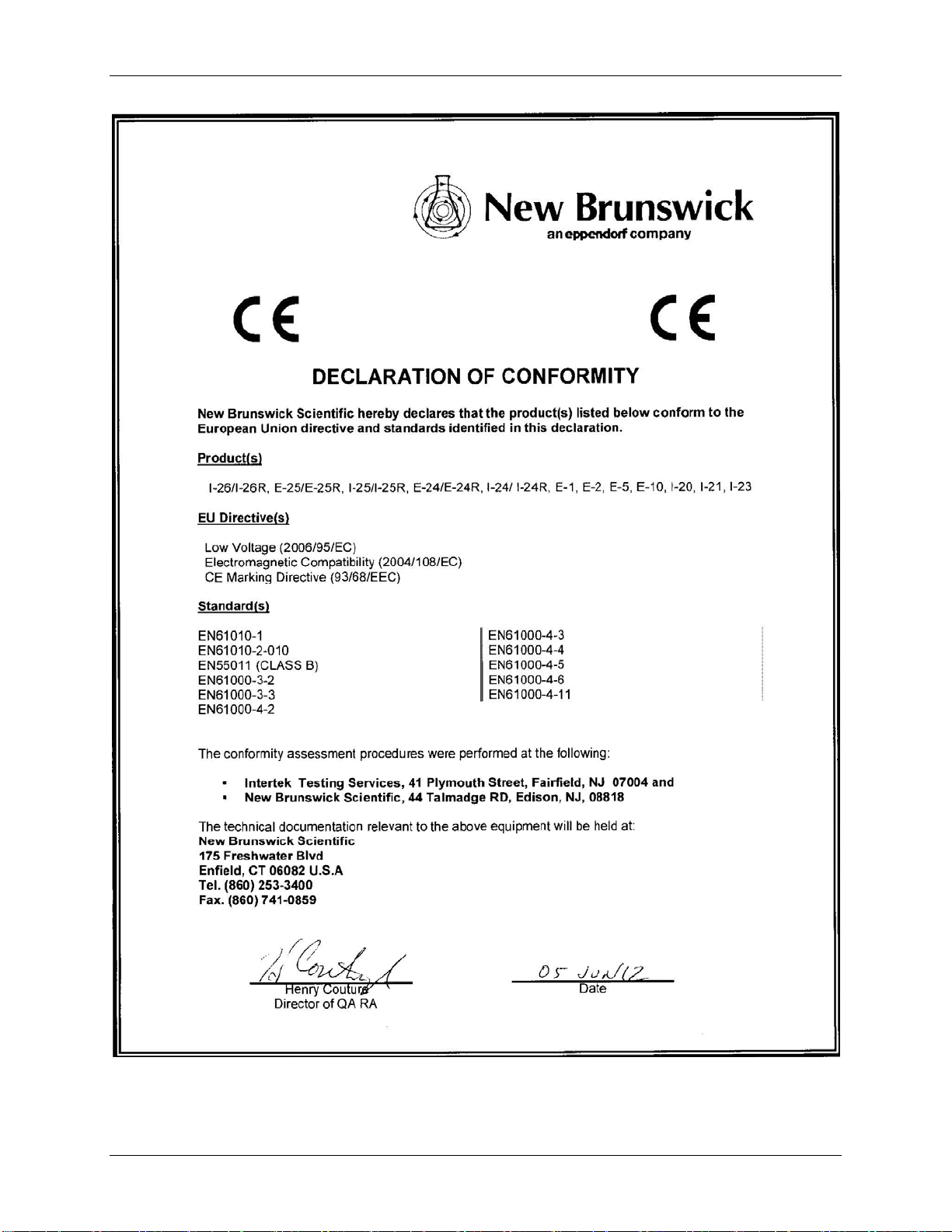
As attested in the CE Declaration of Conformity reproduced on the following page, the
Excella E-24 and E-24R also conform to the appropriate CE standards (see also “CE
Regulatory Standards” in the specifications table).
Excella E-24/24R Incubator Shakers M1352-0050 Operating Manual
Page 43
43
New Brunswick Operating Manual
Page 44

44
A
1122
12.1 Return Procedure
As explained in Section 8.2, should you need to return your Excella E-24/24R to
Eppendorf for any reason, first contact Customer Service to obtain a Returned Material
Authorization (RMA) number. This number must appear on the outside of the shipping
container, otherwise Eppendorf Receiving will refuse to accept the shipment.
In addition, you must also certify that the instrument being returned has been thoroughly
cleaned and decontaminated. A form for this purpose is provided on the following page;
you can photocopy it and fill it out by hand. It can also be downloaded from our website
(www.nbsc.com
A copy of the completed Return Authorization and Decontamination Certificate must be
attached to the outside of the container, with a second copy packed inside with the
instrument.
12.2 Return Authorization and Decontamination Certificate
), if you prefer to fill it out electronically.
PPPPEENNDDIIX
A
X
:
:
P
RROODDUUCCTT
P
R
EETTUURRNNS
R
S
A sample form for you to copy and fill out is provided on the following page.
Excella E-24/24R Incubator Shakers M1352-0050 Operating Manual
Page 45

45
New Brunswick Scientific
Return Authorization and
Decontamination Certificate
Contact Eppendorf for an RMA number prior to returning any equipment, then complete this form and
attach it to the outside container of the equipment being returned to our facility. In addition, please
enclose a completed, duplicate copy of this form with the returned item.
Returned Material Authorization (RMA) Number ____________________
Equipment being returned: Model Number ______________Serial Number__________________
Reason for its return:
______________________________________________________________________________
__________________________________________________________________
This equipment (check all that apply):
New Product Biohazards
Never used Not used
_________________________
Hazardous Chemicals Radioactive Materials
Not used Not used
Used, but decontaminated with Used, but decontaminated with
_________________________ _________________________
I certify that the equipment described above has been thoroughly cleaned and
decontaminated of all chemical, biological and radioactive contaminants and also certify
that the returned unit is safe for unprotected human contact.
By: _______________________________ _________________________________
Signature Print name
Title: ______________________________ Date: ____________________________
Company: ____________________________
Address: ____________________________
____________________________
____________________________
Phone: _________________ Fax: ________________ email: ______________
Used, but decontaminated with
Form 2847
New Brunswick Operating Manual
Page 46

46
A
Accessories, 33
Racks & Trays, 34
Actual Temperature, 22
Alarm Functions, 21
Alarms, 6, 41
Audible Alarm
Disabling the, 21
Muting the, 21
Automatic Restart, 41
B
Belt Replacement, 30
Biohazards, 24
C
Calibrating Speed, 23
Certifications, 42
Checking Setpoints, 20
Clamp Hardware Kits, 34
Cleaning, 24
Continuous Operation, 6
Continuous Run, 20
Control Schematic, 36
Customer Satisfaction Form 6300, 9
D
Declaration of Conformity, 43
Decontamination, 24
Decontamination Certificate, 27, 44, 45
Dimensions
Chamber, 42
Overall, 41
Platform, 42
Double Girdle Clamps, 13
Drawings
List of, 39
Drive, 41
1133
Drive Belt
Removing the, 30
Replacing the, 30
E
Electrical Connections, 14
Electrical Requirements, 10, 41
Electrical Service, 14
Environment, 10
F
Features
Status Indicators, 17
Flask Capacities, 33
Flask Clamp Installation, 13
Flask Clamps, 33
Function Indicators, 17
Fuses, 28
H
Heater, 41
I
Incomplete Order, 9
Index of Drawings, 39
Index of Tables, 40
Indicated Temperature, 22
Inspection
of Boxes, 8
Installation Space, 11
L
LED Display, 16, 41
M
Maintenance, 24
Missing Parts, 9
Motor, 41
I
NNDDEEX
I
X
Excella E-24/24R Incubator Shakers M1352-0050 Operating Manual
Page 47

47
Mute Function, 21
N
Net Weight, 42
O
On/Off Switch
Location of, 19
Operation, 19
Operation Modes, 6
P
Packing List
Verification of, 8
Platform
Available Types, 33
Platforms, 6
Power Failure, 23
Problems, 26
Product Returns, 27, 44
Shipping Damage, 9
Space Requirements, 11
Spare Parts, 32
Specifications, 41
Speed Calibration, 23
Spills, 24
Starting the Unit, 19
Status Indicators, 17
T
Tables
List of, 40
Temperature Correction Value, 22
Temperature Offset Calibration, 22
Temperature Range, 41
Temperature Setpoint, 21
Test Tube Racks, 34
Timed Functions, 20
Timed Run, 6
Troubleshooting, 26
R
Refrigeration Schematic, 39
Replacement Parts, 32
Return Authorization, 27, 44, 45
Returned Material Authorization Number,
27, 44
RMA, 27, 44, 45
RS-232, 41
S
Safety, 41
Safety Switch, 6
Setpoint Retention, 41
Shaking Speed, 41
U
UniCentric™ Drive, 6, 41
Universal Platform, 33
Untimed Run, 20
User Interface Keys, 16
V
Visual Alarm
Disabling the, 21
W
Warranty Registration, 9
New Brunswick Operating Manual
Page 48

Evaluate your operating manual
www.eppendorf.com/manualfeedback
Your local distributor for New Brunswick products: www.nbsc.com/ContactUs
New Brunswick Scientific, 175 Freshwater Boulevard, Enfield, CT 06082-4444 USA
Eppendorf AG • 22331 Hamburg • Germany • Tel: +49 40 538 01-0 • Fax: +49 40 538 01-556 • E-mail: eppendorf@eppendorf.com
New Brunswick Scientific Europe B.V. • Nijmegen • The Netherlands • Tel: +31 (0) 24 3717 600 • E-mail: europe@nbsbv.nl
Eppendorf North America, Inc. • Hauppauge, NY • USA • Tel: +1 516 334 7500 • +1 800 645 3050 • E-mail: info@eppendorf.com
Application Support Europe, International: Tel: +49 1803 666 789 • E-mail: support@eppendorf.com
North America : Tel : +1 800 645 3050 menu option 2 • E-mail: techserv@eppendorf.com
Asia Pacific: Tel: +603 8023 6869 • E-mail: support_asiapacific@eppendorf.com
 Loading...