

Page 1
nualck CO2 Back-up System
EN) manual
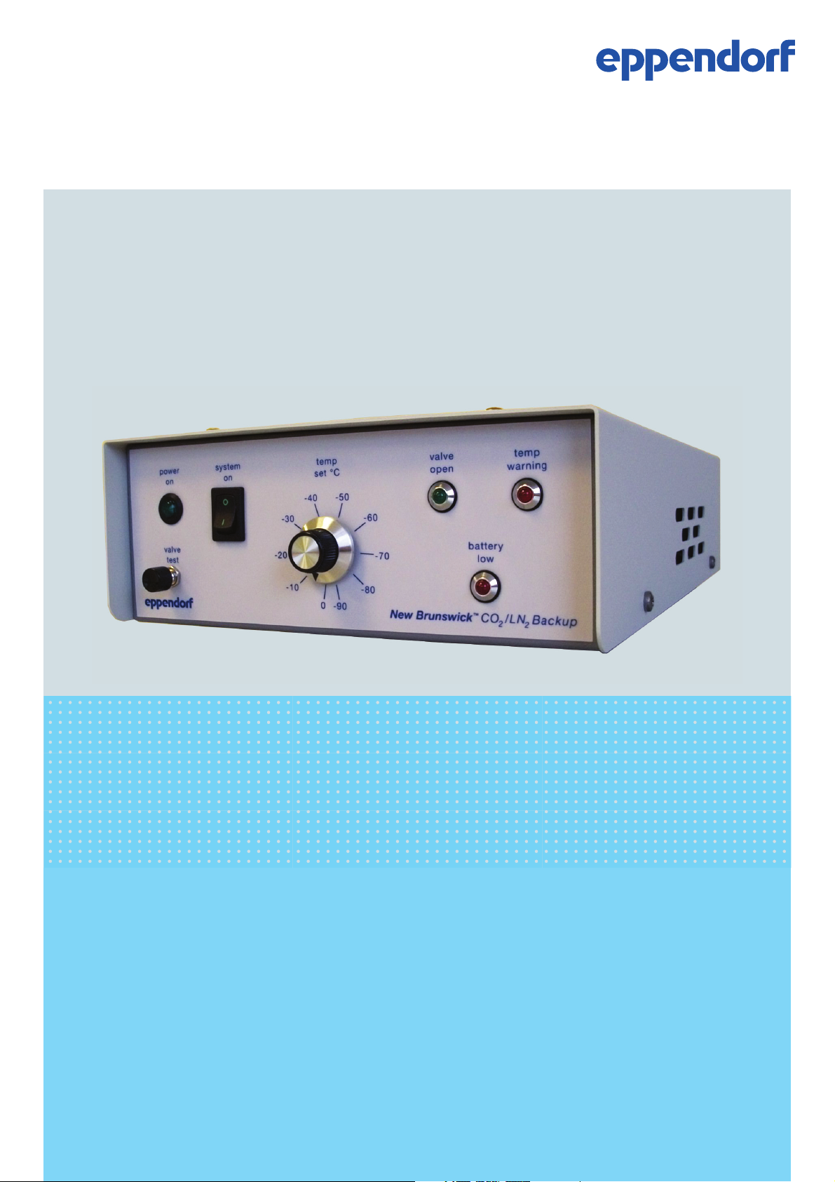
New Brunswick™
CO2 Back-up System
Operating manual
Page 2

Copyright
Copyright © 2014 Eppendorf AG, Germany. No part of this publication may be reproduced without the
prior permission of the copyright owner.
The company reserves the right to change information in this document without notice. Updates to
information in this document reflect our commitment to continuing product development and
improvement.
Trademarks
®
Eppendorf
New Brunswick™ and the New Brunswick
Innova
Trademarks are not marked in all cases with ™ or
and the Eppendorf logo are registered trademarks of Eppendorf AG, Germany.
™
Logo are trademarks of Eppendorf AG, Germany.
®
is a registered trademark of Eppendorf, Inc., USA.
®
in this manual.
Eppendorf has attempted to identify the ownership of all trademarks from public records. Any omissions or
errors are unintentional.
M1288-0055-M/012014
Page 3

Table of contents
New Brunswick CO2 Back-up System
English (EN)
Table of contents
1 Operating instructions . . . . . . . . . . . . . . . . . . . . . . . . . . . . . . . . . . . . . . . . . . . . . . . . . . . . . . . . . . . . . . 5
1.1 Using this manual . . . . . . . . . . . . . . . . . . . . . . . . . . . . . . . . . . . . . . . . . . . . . . . . . . . . . . . . . . . . . 5
1.2 Danger symbols and danger levels . . . . . . . . . . . . . . . . . . . . . . . . . . . . . . . . . . . . . . . . . . . . . . . . 5
1.2.1 Hazard icons . . . . . . . . . . . . . . . . . . . . . . . . . . . . . . . . . . . . . . . . . . . . . . . . . . . . . . . . . . 5
1.2.2 Degrees of danger . . . . . . . . . . . . . . . . . . . . . . . . . . . . . . . . . . . . . . . . . . . . . . . . . . . . . . 5
1.3 Symbols used . . . . . . . . . . . . . . . . . . . . . . . . . . . . . . . . . . . . . . . . . . . . . . . . . . . . . . . . . . . . . . . . 5
2 Safety. . . . . . . . . . . . . . . . . . . . . . . . . . . . . . . . . . . . . . . . . . . . . . . . . . . . . . . . . . . . . . . . . . . . . . . . . . . . 7
2.1 Intended use . . . . . . . . . . . . . . . . . . . . . . . . . . . . . . . . . . . . . . . . . . . . . . . . . . . . . . . . . . . . . . . . . 7
2.2 User profile . . . . . . . . . . . . . . . . . . . . . . . . . . . . . . . . . . . . . . . . . . . . . . . . . . . . . . . . . . . . . . . . . . 7
2.3 Information on product liability . . . . . . . . . . . . . . . . . . . . . . . . . . . . . . . . . . . . . . . . . . . . . . . . . . 7
2.4 Warnings for intended use . . . . . . . . . . . . . . . . . . . . . . . . . . . . . . . . . . . . . . . . . . . . . . . . . . . . . . 7
2.4.1 Personal injury and damage to device . . . . . . . . . . . . . . . . . . . . . . . . . . . . . . . . . . . . . . 7
2.4.2 Incorrect handling of accessories . . . . . . . . . . . . . . . . . . . . . . . . . . . . . . . . . . . . . . . . . . 8
3
3 Product description . . . . . . . . . . . . . . . . . . . . . . . . . . . . . . . . . . . . . . . . . . . . . . . . . . . . . . . . . . . . . . . . 9
3.1 Main illustration . . . . . . . . . . . . . . . . . . . . . . . . . . . . . . . . . . . . . . . . . . . . . . . . . . . . . . . . . . . . . . 9
4 Transport, storage and disposal . . . . . . . . . . . . . . . . . . . . . . . . . . . . . . . . . . . . . . . . . . . . . . . . . . . . . 11
4.1 Transport. . . . . . . . . . . . . . . . . . . . . . . . . . . . . . . . . . . . . . . . . . . . . . . . . . . . . . . . . . . . . . . . . . . 11
4.2 Disposal. . . . . . . . . . . . . . . . . . . . . . . . . . . . . . . . . . . . . . . . . . . . . . . . . . . . . . . . . . . . . . . . . . . . 11
5 Introduction . . . . . . . . . . . . . . . . . . . . . . . . . . . . . . . . . . . . . . . . . . . . . . . . . . . . . . . . . . . . . . . . . . . . . 13
5.1 Scope of manual . . . . . . . . . . . . . . . . . . . . . . . . . . . . . . . . . . . . . . . . . . . . . . . . . . . . . . . . . . . . . 13
5.2 CO
Back-up System . . . . . . . . . . . . . . . . . . . . . . . . . . . . . . . . . . . . . . . . . . . . . . . . . . . . . . . . . . 13
2
5.3 Product versions . . . . . . . . . . . . . . . . . . . . . . . . . . . . . . . . . . . . . . . . . . . . . . . . . . . . . . . . . . . . . 14
6 Installation . . . . . . . . . . . . . . . . . . . . . . . . . . . . . . . . . . . . . . . . . . . . . . . . . . . . . . . . . . . . . . . . . . . . . . 15
6.1 Before installation . . . . . . . . . . . . . . . . . . . . . . . . . . . . . . . . . . . . . . . . . . . . . . . . . . . . . . . . . . . . 15
6.2 Selecting the location . . . . . . . . . . . . . . . . . . . . . . . . . . . . . . . . . . . . . . . . . . . . . . . . . . . . . . . . . 15
6.3 Unpacking the device . . . . . . . . . . . . . . . . . . . . . . . . . . . . . . . . . . . . . . . . . . . . . . . . . . . . . . . . . 15
6.4 Temperature sensor installation . . . . . . . . . . . . . . . . . . . . . . . . . . . . . . . . . . . . . . . . . . . . . . . . . 16
6.4.1 Temperature sensor installation for upright freezers . . . . . . . . . . . . . . . . . . . . . . . . . . 16
6.4.2 Temperature sensor installation for chest freezers. . . . . . . . . . . . . . . . . . . . . . . . . . . . 16
6.5 Manifold-to-solenoid valve transfer line assembly . . . . . . . . . . . . . . . . . . . . . . . . . . . . . . . . . . . 17
6.5.1 Manifold-to-solenoid valve transfer line assembly for upright freezers (including Model
U101)17
6.5.2 Manifold-to-solenoid valve transfer line assembly for chest freezers. . . . . . . . . . . . . . 17
6.6 Solenoid valve to freezer installation . . . . . . . . . . . . . . . . . . . . . . . . . . . . . . . . . . . . . . . . . . . . . 17
6.6.1 Solenoid valve installation for upright freezers . . . . . . . . . . . . . . . . . . . . . . . . . . . . . . 17
6.6.2 Solenoid valve installation for chest freezers . . . . . . . . . . . . . . . . . . . . . . . . . . . . . . . . 17
6.7 Installing more 0.6 m (2 ft) transfer lines to manifold . . . . . . . . . . . . . . . . . . . . . . . . . . . . . . . . 18
6.7.1 Installing 0.6 m (2 ft) transfer line to manifold . . . . . . . . . . . . . . . . . . . . . . . . . . . . . . . 18
6.8 CO
gas supply installation . . . . . . . . . . . . . . . . . . . . . . . . . . . . . . . . . . . . . . . . . . . . . . . . . . . . . 18
2
6.9 Test for gas leaks. . . . . . . . . . . . . . . . . . . . . . . . . . . . . . . . . . . . . . . . . . . . . . . . . . . . . . . . . . . . . 18
6.10 Door switch installation . . . . . . . . . . . . . . . . . . . . . . . . . . . . . . . . . . . . . . . . . . . . . . . . . . . . . . . 19
6.11 Installing cables to back of control unit . . . . . . . . . . . . . . . . . . . . . . . . . . . . . . . . . . . . . . . . . . . 20
Page 4

Table of contents
New Brunswick CO2 Back-up System
4
English (EN)
7 Operation. . . . . . . . . . . . . . . . . . . . . . . . . . . . . . . . . . . . . . . . . . . . . . . . . . . . . . . . . . . . . . . . . . . . . . . . 21
7.1 Turning the control unit on. . . . . . . . . . . . . . . . . . . . . . . . . . . . . . . . . . . . . . . . . . . . . . . . . . . . . 21
7.2 Testing the solenoid valve. . . . . . . . . . . . . . . . . . . . . . . . . . . . . . . . . . . . . . . . . . . . . . . . . . . . . . 21
7.3 Testing door switch. . . . . . . . . . . . . . . . . . . . . . . . . . . . . . . . . . . . . . . . . . . . . . . . . . . . . . . . . . . 21
7.4 Testing back-up system operation . . . . . . . . . . . . . . . . . . . . . . . . . . . . . . . . . . . . . . . . . . . . . . . 22
7.5 Battery back-up. . . . . . . . . . . . . . . . . . . . . . . . . . . . . . . . . . . . . . . . . . . . . . . . . . . . . . . . . . . . . . 22
7.6 Alarm system monitoring socket. . . . . . . . . . . . . . . . . . . . . . . . . . . . . . . . . . . . . . . . . . . . . . . . . 23
8 Maintenance . . . . . . . . . . . . . . . . . . . . . . . . . . . . . . . . . . . . . . . . . . . . . . . . . . . . . . . . . . . . . . . . . . . . . 25
8.1 Cleaning . . . . . . . . . . . . . . . . . . . . . . . . . . . . . . . . . . . . . . . . . . . . . . . . . . . . . . . . . . . . . . . . . . . 25
8.1.1 Cleaning the device . . . . . . . . . . . . . . . . . . . . . . . . . . . . . . . . . . . . . . . . . . . . . . . . . . . . 25
8.1.2 Cleaning the surrounding area . . . . . . . . . . . . . . . . . . . . . . . . . . . . . . . . . . . . . . . . . . . 25
8.2 CO
bottle maintenance . . . . . . . . . . . . . . . . . . . . . . . . . . . . . . . . . . . . . . . . . . . . . . . . . . . . . . . 25
2
8.3 Electrical connection maintenance . . . . . . . . . . . . . . . . . . . . . . . . . . . . . . . . . . . . . . . . . . . . . . . 26
8.4 Battery maintenance . . . . . . . . . . . . . . . . . . . . . . . . . . . . . . . . . . . . . . . . . . . . . . . . . . . . . . . . . . 26
8.5 Transfer line and manifold maintenance . . . . . . . . . . . . . . . . . . . . . . . . . . . . . . . . . . . . . . . . . . 26
8.6 Maintenance forms . . . . . . . . . . . . . . . . . . . . . . . . . . . . . . . . . . . . . . . . . . . . . . . . . . . . . . . . . . . 26
8.7 CO
/LN2 back-up system service checklist . . . . . . . . . . . . . . . . . . . . . . . . . . . . . . . . . . . . . . . . . 27
2
9 Technical data. . . . . . . . . . . . . . . . . . . . . . . . . . . . . . . . . . . . . . . . . . . . . . . . . . . . . . . . . . . . . . . . . . . . 29
9.1 Performance . . . . . . . . . . . . . . . . . . . . . . . . . . . . . . . . . . . . . . . . . . . . . . . . . . . . . . . . . . . . . . . . 29
9.2 Weight/dimensions . . . . . . . . . . . . . . . . . . . . . . . . . . . . . . . . . . . . . . . . . . . . . . . . . . . . . . . . . . . 29
9.2.1 Device dimensions . . . . . . . . . . . . . . . . . . . . . . . . . . . . . . . . . . . . . . . . . . . . . . . . . . . . 29
9.2.2 Device weight . . . . . . . . . . . . . . . . . . . . . . . . . . . . . . . . . . . . . . . . . . . . . . . . . . . . . . . . 29
9.3 Cable and transfer line lengths . . . . . . . . . . . . . . . . . . . . . . . . . . . . . . . . . . . . . . . . . . . . . . . . . . 29
9.4 Power supply. . . . . . . . . . . . . . . . . . . . . . . . . . . . . . . . . . . . . . . . . . . . . . . . . . . . . . . . . . . . . . . . 29
9.5 Fuses . . . . . . . . . . . . . . . . . . . . . . . . . . . . . . . . . . . . . . . . . . . . . . . . . . . . . . . . . . . . . . . . . . . . . . 29
9.6 Ambient conditions . . . . . . . . . . . . . . . . . . . . . . . . . . . . . . . . . . . . . . . . . . . . . . . . . . . . . . . . . . . 30
9.6.1 Device operating environment . . . . . . . . . . . . . . . . . . . . . . . . . . . . . . . . . . . . . . . . . . . 30
9.7 Gas Consumption . . . . . . . . . . . . . . . . . . . . . . . . . . . . . . . . . . . . . . . . . . . . . . . . . . . . . . . . . . . . 30
9.8 CO
Supplies . . . . . . . . . . . . . . . . . . . . . . . . . . . . . . . . . . . . . . . . . . . . . . . . . . . . . . . . . . . . . . . . 31
2
9.9 Spare parts . . . . . . . . . . . . . . . . . . . . . . . . . . . . . . . . . . . . . . . . . . . . . . . . . . . . . . . . . . . . . . . . . 32
9.10 Circuit Schematics . . . . . . . . . . . . . . . . . . . . . . . . . . . . . . . . . . . . . . . . . . . . . . . . . . . . . . . . . . . 33
10 Declaration of conformity . . . . . . . . . . . . . . . . . . . . . . . . . . . . . . . . . . . . . . . . . . . . . . . . . . . . . . . . . . 35
Index . . . . . . . . . . . . . . . . . . . . . . . . . . . . . . . . . . . . . . . . . . . . . . . . . . . . . . . . . . . . . . . . . . . . . . . . . . . 37
Page 5
Operating instructions
New Brunswick CO2 Back-up System
English (EN)
1 Operating instructions
1.1 Using this manual
Carefully read this operating manual before using the device for the first time.
Also observe the operating manual enclosed with the accessories.
This operating manual should be considered part of the product and stored in a location that is easily
accessible.
Include this operating manual when forwarding the device to third parties.
If this manual is lost, please request another one. The latest version can be found on our website
www.eppendorf.com (international) or www.eppendorfna.com (North America).
1.2 Danger symbols and danger levels
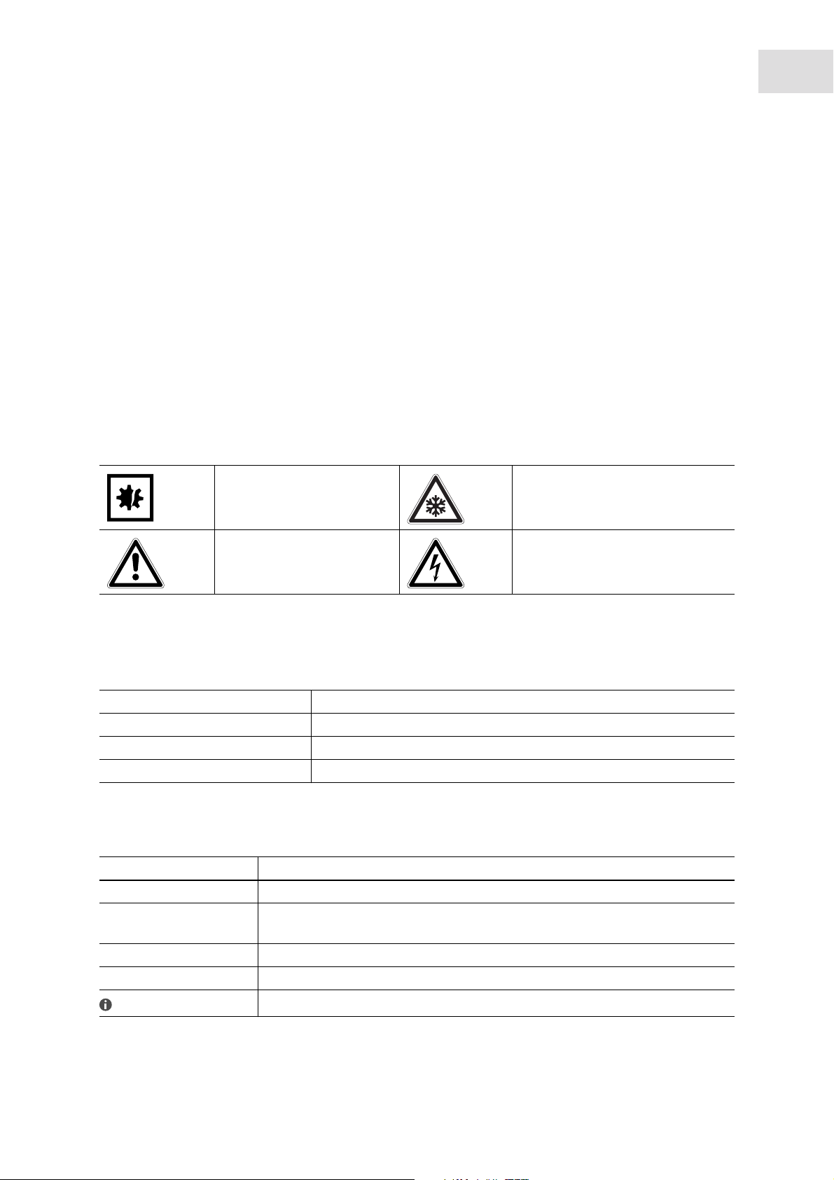
1.2.1 Hazard icons
5
Material damage Freezer burn
Hazard point Electric shock
1.2.2 Degrees of danger
The following danger levels are used in safety messages throughout this manual.
DANGER Will lead to severe injuries or death.
WARNING May lead to severe injuries or death.
CAUTION May lead to light to moderate injuries.
NOTICE May lead to material damage.
1.3 Symbols used
Depiction Meaning
You are requested to perform an action.
1.
2.
• List
Text Terms and labels of the graphic user interface.
Perform these actions in the sequence described.
References useful information.
Page 6

Operating instructions
New Brunswick CO2 Back-up System
6
English (EN)
Page 7
Safety
New Brunswick CO2 Back-up System
English (EN)
2 Safety
2.1 Intended use
The CO2 Back-up System is exclusively intended for indoor use and for and to maintain inside temperature
of all Innova and Premium freezers in case of power failure.
2.2 User profile
The device may only be operated by trained lab personnel who have carefully read this operating manual
and are familiar with the device functions.
2.3 Information on product liability
In the following cases, the designated protection of the device may be compromised.
7
The liability for the function of the device passes to the operator if:
• The device is not used in accordance with this operating manual.
• The device is used outside of the range of application described in the succeding chapters.
• The device is used with accessories or consumables that were not approved by Eppendorf.
• Service or maintenance is completed on the device by people who are not authorized by Eppendorf.
• The owner has made unauthorized modifications to the device.
2.4 Warnings for intended use
Before using the device, read this operating manual and observe the following general safety instructions.
2.4.1 Personal injury and damage to device
WARNING! Electric shock due to damage to the device or power cable
Only switch on the device if the device and power cable are undamaged.
Only use devices that have been properly installed or repaired.
WARNING! Danger due to incorrect power supply
Only connect the device to voltage sources that meet the requirements on the name plate.
Only use sockets with a protective earth (PE) conductor and suitable power cable.
WARNING! Direct contact with cold contents inside the freezer can burn unprotected skin
Use freezer gloves at all times when loading or unloading equipment.
Page 8

Safety
New Brunswick CO2 Back-up System
8
English (EN)
2.4.2 Incorrect handling of accessories
CAUTION! Lack of safety due to incorrect accessories or spare parts
Accessories and spare parts that are not recommended by Eppendorf compromise the safety,
function and precision of the device. Eppendorf cannot be held liable or accept any liability for
damage resulting from the use of non-recommended accessories and spare parts.
Only use accessories and original spare parts recommended by Eppendorf.
Page 9
3 Product description
3.1 Main illustration
Product description
New Brunswick CO2 Back-up System
English (EN)
9
Abb. 3-1: Front view of the CO2 Back-up System
1
2
6
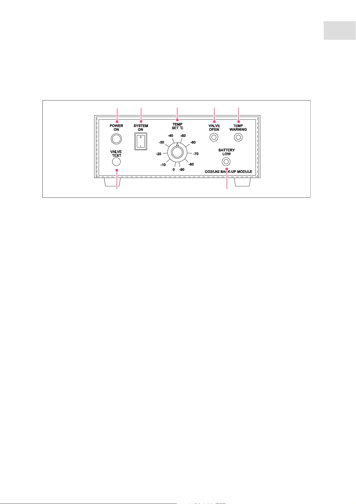
Fig. 3-1: Front view of the CO2 Back-up System
1 Power On LED
Illuminates when device is plugged into the
mains
2 System On Switch
Turns the device on or off
3 Temp Set Dial
Sets the back-up temperature in case of power
failure
3
4 5
7
5 Temp Warning LED
Illuminates when internal freezer temp drops
below set temperature on the Temp Set Knob
6 Valve Test Button
Button to push to test CO
injection
2
7 Battery Low LED
Illuminates when back-up battery inside device is
low
4 Valve Open LED
Illuminates when CO
valve is open
2
Page 10
10
Product description
New Brunswick CO2 Back-up System
English (EN)
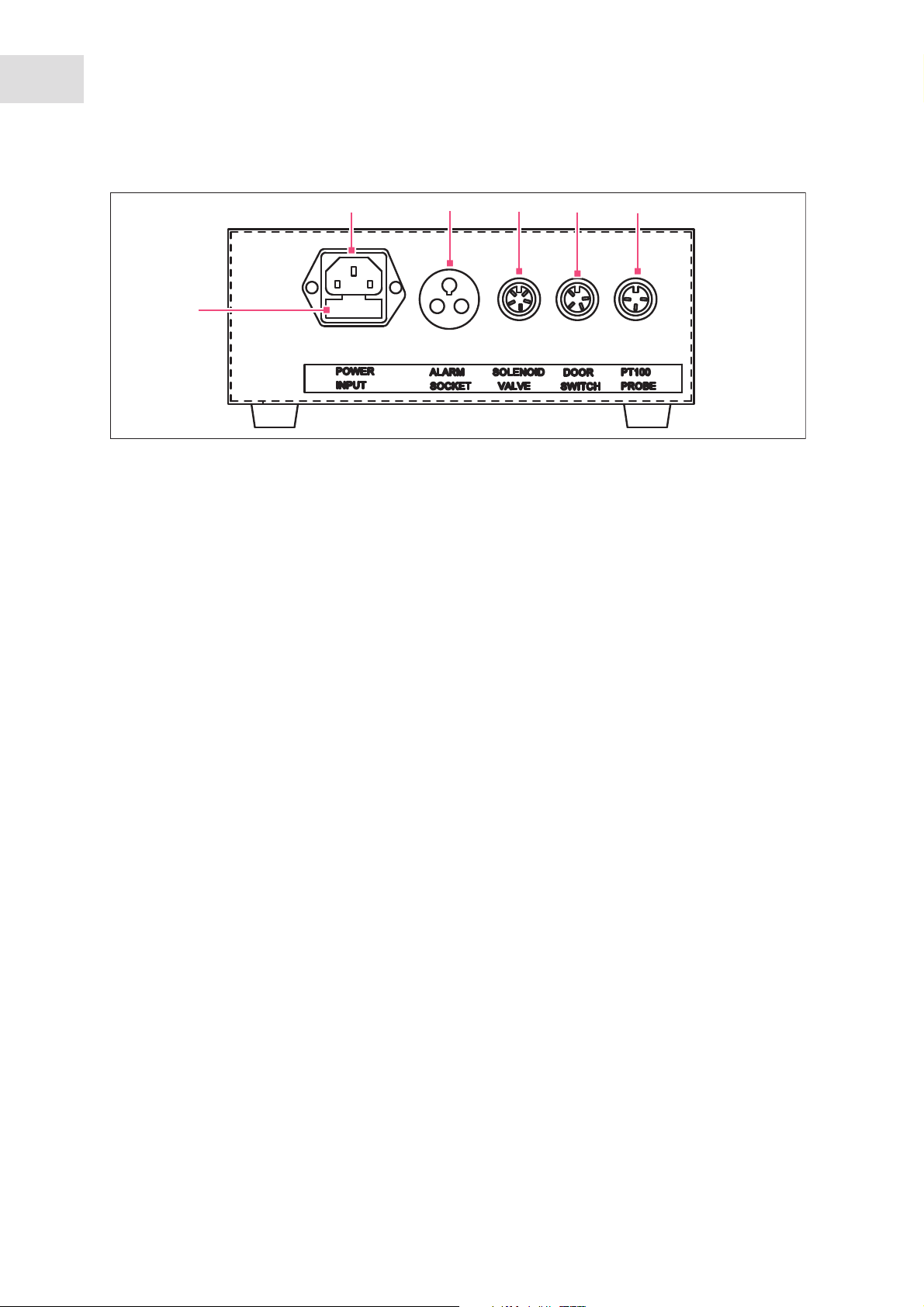
Abb. 3-2: Back view of the CO2 Back-up System
8
13
Fig. 3-2: Back view of the CO2 Back-up System
8 Power Input Socket
Insertion point for power cord
9 Alarm Socket
10 Solenoid Valve Socket
5P DIN
9
10
11
11 Door Switch Socket
4P DIN
12 PT100 Probe Socket
3P DIN
13 Main Fuses
12
Page 11
Transport, storage and disposal
New Brunswick CO2 Back-up System
English (EN)
4 Transport, storage and disposal
4.1 Transport
NOTICE! Improper transportation
Only transport product in its original packaging
4.2 Disposal
In case the product is to be disposed of, the relevant legal regulations are to be observed.
Information on the disposal of electrical and electronic devices in the European Community:
11
Within the European Community, the disposal of electrical devices is regulated by national regulations
based on EU Directive 2002/96/EC pertaining to waste electrical and electronic equipment (WEEE).
According to these regulations, any devices supplied after August 13, 2005, in the business-to-business
sphere, to which this product is assigned, may no longer be disposed of in municipal or domestic waste. To
document this, they have been marked with the following identification:
Because disposal regulations may differ from one country to another within the EU, please contact your
supplier if necessary.
In Germany, this is mandatory from March 23, 2006. From this date, the manufacturer has to offer a
suitable method of return for all devices supplied after August 13, 2005. For all devices supplied before
August 13, 2005, the last user is responsible for the correct disposal.
Page 12

12
Transport, storage and disposal
New Brunswick CO2 Back-up System
English (EN)
Page 13

Introduction
New Brunswick CO2 Back-up System
English (EN)
5 Introduction
5.1 Scope of manual
This manual provides the user with the necessary information for the installation and operation of the CO2
®
Back-up System for New Brunswick Scientific’s Innova
and Premium -45 and -86 ranges of Ultra Low
Temperature Freezers.
5.2 CO2 Back-up System
The CO2 Back-up System system is designed to provide a means of maintaining the contents of a New
Brunswick Scientific Ultra Low Temperature Freezer at a preset temperature should the power or the
refrigeration system fail.
The freezer is fitted with a platinum resistance thermometer (referred to as a temperature sensor or probe)
to measure the internal temperature, a solenoid valve and a door switch.
13
A freestanding control unit and cables are provided. Transfer lines and connectors are supplied to connect
between the solenoid valve and the CO
NOTICE! Liquid CO
Liquid CO
is required, NOT gas. Bottles containing liquid CO2 fitted with full-length dip
2
bottle. Bottles are not provided.
2
required
2
tubes must be used.
The back-up system is plugged into the power supply and a temperature selected between 0 °C and -70 °C
on the Temp Set dial. When the temperature within the freezer rises above the selected back-up
temperature, the injector switches on. CO
gas is released in pulses of approximately two-second bursts,
2
then a fifteen-second delay.
The solenoid valve continues to inject gas until the temperature within the freezer drops below the preset
value selected on the Temp Set dial. If a power failure occurs, a battery within the back-up unit will
continue to operate the back-up system for up to 48 hours.
When the door or lid of the freezer is opened, the door switch is activated to prevent additional gas
injections while the freezer is open. This prevents the freezer user from being burned by the extremely cold
gas stream.
Page 14

14
Introduction
New Brunswick CO2 Back-up System
English (EN)
5.3 Product versions
There are four versions of the product:
Back-up Systems
Freezer type Part number
Innova 115 V / 220 V 60 Hz CGA Bottle Fitting U9043-0002
Innova 230 V 50 Hz BS341 Bottle Fitting U9043-0004
Premium 115 V / 220 V 60 Hz CGA Bottle Fitting U9043-0006
Premium 230 V 50 Hz BS341 Bottle Fitting U9043-0008
Page 15

Installation
New Brunswick CO2 Back-up System
English (EN)
6 Installation
6.1 Before installation
DANGER! Damage to device
Empty freezer before installation of device.
Open the door or lid of freezer and let reach ambient temperature.
The back-up unit cannot be fitted to a freezer that is operating!
Before installation, empty the freezer, switch it off, and disconnect it from the power outlet. Open the door
or lid and let the whole freezer reach ambient temperature.
15
6.2 Selecting the location
Select the location according to the following criteria:
• Position the control unit such that the disconnect device - the mains/power plug is easily accessible.
• Suitable mains power connection according to the ID plate
• Stable, level base
• Well ventilated area
• Ambient temperature of 5 °C to 32 °C
• Ambient humidity of 80 % at 31 °C
• Ambient humidity of 50 % at 40 °C
• Up to 2000 m
6.3 Unpacking the device
NOTICE! Damage due to incorrect usage
Only use the device for the intended use described in the operating manual.
Ensure adequate material resistance when using chemical substances.
If in doubt, contact Eppendorf.
Keep the packing material and transport securing device for later transport or storage.
Carefully unwrap the back-up unit and retain the packing materials for possible future use.
Check that all the items listed on the packing shipping list are present. Inspect all items for damage that
may have occurred during delivery. Report any damage or deficiencies to your local Eppendorf sales
representative.
Page 16

16
Installation
New Brunswick CO2 Back-up System
English (EN)
6.4 Temperature sensor installation
The temperature sensor is fitted to the freezer through the port fitted with a nylon plug. The hole is located
on either (a) the top panel, in the rear right-hand corner on upright models (except for the Model U101: see
note below), or (b) inside the compressor compartment on chest models.
On the U101 Innova freezer, the temperature sensor port is located on the left-hand side wall.
6.4.1 Temperature sensor installation for upright freezers
1. The temperature sensor is fitted through one of the two plugged ports.
2. Remove the plug that is not surrounded by four screws.
3. Insert the temperature sensor through the hole in the black blanking plug provided, pressing the
grommet on the sensor cable into the hole to seal.
4. Insert the temperature sensor through one of the insulation tubes provided and push the sensor and
insulation tube into the cabinet port.
5. Press the nylon plug into the hole.
6. Inside the freezer cabinet, position the temperature sensor next to the existing freezer temperature
sensor. The existing freezer temperature sensor is located halfway into the cabinet. (For the model U101
freezer, the temperature sensor cable should be secured to the left side of the internal cabinet and pass
under the fixed shelf. Position the CO
sensor).
7. Secure the CO
temperature sensor to the freezer temperature sensor using one of the plastic cable ties
2
provided.
8. Secure the temperature sensor cable to the two attachment points (plastic clips) attached to the cabinet.
temperature sensor next to the existing freezer temperature
2
6.4.2 Temperature sensor installation for chest freezers
1. Remove the right side cover of the frezer to expose the compressor compartment.
2. Looking into the compressor compartment, at the top left-hand corner, the existing freezer temperature
sensor can be seen passing into the freezer cabinet. The CO
through the same port.
3. Create a hole through the insulation next to the freezer temperature sensor by inserting a length of 1/
4-inch or ~6mm metal rod or tube through the insulation to create a passage for the probe (keeping the
rod or tube perpendicular to the cabinet wall when inserting through the insulation).
4. After creating the new hole, push the CO
temperature sensor through the hole and pull enough
2
temperature sensor cable through the hole to reach the freezer temperature sensor, located
approximately halfway down the front right corner, inside the freezer cabinet.
5. Remove freezer temperature sensor cover and position the two sensors side-by-side.
6. Fasten the two sensors with the plastic cable ties provided.
7. Replace the temperature sensor cover.
temperature sensor should be fitted
2
Page 17

Installation
New Brunswick CO2 Back-up System
English (EN)
6.5 Manifold-to-solenoid valve transfer line assembly
The manifold-to-solenoid valve transfer line assembly consists of the brass, six position block manifold, the
2.0 m (6.6 ft) transfer line, and the solenoid valve.
6.5.1 Manifold-to-solenoid valve transfer line assembly for upright freezers (including
Model U101)
1. Insert the free end of the 2.0 m (6.6 ft) transfer line into the solenoid valve assembly.
2. Rotate the fitting clockwise to tighten.
6.5.2 Manifold-to-solenoid valve transfer line assembly for chest freezers
1. Remove the compressor housing panel.
2. Remove the 2-inch blanking plug from the rear panel of the freezer.
3. Insert the free end of the 2.0 m (6.6 ft)transfer line into the solenoid valve. Pull enough hose through to
reach the solenoid valve.
4. Rotate fitting clockwise to tighten.
17
6.6 Solenoid valve to freezer installation
The solenoid valve is fitted to the freezer through the port fitted with a nylon plug and surrounded by a ring
of four screws. The port is located (a) on the top panel, in the rear right-hand corner on Upright models
(except for the Model U101: see NOTE below), or (b) inside the compressor compartment on Chest models.
NOTE: On the U101 Innova freezer, the injector port is located on the left-hand side wall.
6.6.1 Solenoid valve installation for upright freezers
1. Remove the nylon plug and the 4 screws surrounding the plug. Retain the screws for reuse.
2. Remove the protective cap from the end of the solenoid valve injector pipe.
3. Slide the square attachment plate with the central hole over the copper solenoid valve pipe.
4. Slide the insulation tube over the solenoid valve injection pipe.
5. Push the solenoid valve injector pipe with insulation tube into the exposed port in the freezer cabinet.
6. Slide the U-shaped bracket onto the slot of the solenoid valve body.
7. Secure the two plates to the body with the 4 screws that were set aside for reuse.
8. Tighten screws evenly to lock the solenoid valve into position.
6.6.2 Solenoid valve installation for chest freezers
1. Locate the port for the solenoid assembly on the upper right-hand side of the compressor compartment.
2. Remove the protective cap from the end of the solenoid valve injector pipe.
3. Slide the square attachment plate with the central hole over the solenoid valve injector pipe.
Page 18

18
Installation
New Brunswick CO2 Back-up System
English (EN)
4. Slide the insulation tube over the copper solenoid valve pipe.
5. Push the solenoid valve injector pipe with insulation tube into the exposed port in the freezer cabinet.
6. Slide the U-shaped bracket onto the slot of the solenoid valve body.
7. Secure the two plates to the body with the 4 screws that were set aside for reuse.
8. Tighten screws evenly to lock the injector and solenoid valve into position.
6.7 Installing more 0.6 m (2 ft) transfer lines to manifold
The kit is supplied with two 0.6 m (2 ft) transfer lines. These these transfer lines are attached from the CO2
bottles to the brass manifold. One 0.6 m (2 ft) transfer line is pre-attached to the end of the manifold. If
more than two CO
port on brass manifold), additional transfer lines can be purchased if required. If only one bottle is to be
used, the second supplied hose can be kept as a spare. CO
bottles will be used (up to five transfer lines and bottles can be connected; one for each
2
bottles are not supplied.
2
6.7.1 Installing 0.6 m (2 ft) transfer line to manifold
1. Remove the banking plug on one of the ports of the brass manifold with a hex key.
2. Place the Dowty seal over the threaded end of the 0.6 m (2 ft) transfer line.
3. Screw the 0.6 m (2 ft) transfer line into the threaded port on the brass manifold.
6.8 CO2 gas supply installation
1. Position the CO2 bottle(s) within 2m (6.6 ft) of the freezer. Secure them to the wall or place them in a
safety bottle rack to make sure they cannot fall or cause injury.
2. Attach the 0.6 m (2 ft) transfer line(s) to the CO
attached to each hose to make a proper seal to the CO
washer be used each time a CO
bottle is changed). Do not overtighten the fitting as the plastic washer
2
bottle(s) using the supplied plastic sealing washer
2
bottle fitting (it is recommended that a new
2
can be crushed and gas will leak.
6.9 Test for gas leaks
Before continuing with installation, ensure there are no gas leaks with the following procedure:
WARNING! Leaking gas
Regularly check device parts for leaks
Replace plastic seal after each CO
1. Ensure all fittings are tight before testing.
2. Apply liquid soap solution on each joint.
3. Turn CO
on.
2
tank exchange
2
Page 19

Installation
New Brunswick CO2 Back-up System
English (EN)
Bubbling or foaming will identify leaks.
4. Retighten the fitting or replace the seals if necessary.
6.10 Door switch installation
The magnetic door switch is composed of two separate items (magnet and magnet sensor) and is installed
on (a) the top left-hand surface of the door on Upright models (top right-hand surface of the door on the
model U101) or (b) the rear, right-hand surface of the lid on Chest models.
For Innova Freezers and the Premium U700, use the two, small metal adapter plates supplied. Install the
magnet and magnetic sensor to the adaptor plates using the attached fittings. When attaching to a
Premium freezer, the adapter plates are not used and the magnetic sensor assembly is attached directly to
the freezer cabinet and door.
19
1
5
6
1 Door switch cable
(Attached to sensor)
2 Attachment nuts
3 Magnet
4 Attachment screws
(Must be removed before installation. Retain
screws on door for attaching the magnet.)
2
4
8
3
7
5 Adapter plates
6 Freezer case
7 Freezer door
8 Installed doorswitch
Page 20

20
Installation
New Brunswick CO2 Back-up System
English (EN)
1. Remove the two screws on the lid or door of the freezer and retain for re-use.
2. Fasten the door switch magnet in place using the two screws removed above. The magnet should face
toward the case of the freezer. The magnet portion of the sensor can be identified by the lack of
electrical wires
3. Remove the screws on the case of the freezer.
CAUTION! Failure of system to operate correctly
Ensure magnetic door switch is installed correctly
4. Using the screws provided, fasten the magnet sensor that has the electrical cable attached.
5. Close the lid or door to check that the two parts of the switch do not touch. There should be a gap of no
more than 3 - 10 mm (0.12 - 0.4 inches).
6. If gap is larger than 10 mm, or less than 3 mm, loosen the screws and adjust the magnet until the gap is
corrected.
7. Tighten screws.
6.11 Installing cables to back of control unit
Note: Some kits are supplied with more than one removable power cord. Use the power cord that matches
your power receptacle. Check the voltage rating plate on the underside of the control unit to confirm that
the system is compatible with your laboratory power supply.
1. Place the control unit on top surface of upright freezer, or on compressor compartment of chest freezer.
2. Plug solenoid valve cable into appropriate socket (labelled Solenoid Valve on back of unit).
3. Plug temperature sensor cable into appropriate socket (labelled PT100 Probe).
4. Plug door switch cable into the appropriate socket (labelled Door Switch).
CAUTION! Failure of system
Ensure that the control unit's voltage rating matches you electrical supply
Do not plug in unit if you are not sure of electrical supply voltage rating
5. Choose appropriate power cord to use. Sytem is capable of operating within this voltage range: 100/
240 V 50/60 Hz
6. Insert power cord into socket on back of system.
7. Plug power cord into mains.
Only use approved power cords with the correct rating. Contact Eppendorf sales office for
replacement cords.
Page 21

Operation
New Brunswick CO2 Back-up System
English (EN)
7 Operation
7.1 Turning the control unit on
1. Plug the power cord into the mains.
The green Power On LED illuminates.
2. Turn the System On switch to the on position.
The control unit will beep. The alarm may sound if the control unit has not been switched on for some
time. In this case, the alarm will continue to sound until the battery has been charged or replaced with a
fully charged battery.
The Temp Warning light will illuminate, indicating the temperature in the freezer is warmer than the
temperature set on the Back-up Unit.
7.2 Testing the solenoid valve
1. Unplug freezer.
2. Close the door or lid of freezer.
3. Turn the System On switch on.
4. Turn CO
The Valve Open LED will pulse on and off indicating gas injection.
supply on.
2
21
WARNING! High pressure
Do not keep Valve open for more than 2 seconds at a time.
Allow 15 seconds before pushing Valve Test button again.
5. Push the Valve Test button and hold for no more than 2 seconds at a time.
The Valve Open light will illuminate and CO
the Valve Test button.
6. Release the Valve Test button.
The front panel LED's will illuminate in sequence, in a clockwise direction.
7. Confirm that gas has been flowing by determining the presence of frozen condensation around the
injector and on the freezer's shelf.
will be injected into the freezer for however long you push
2
7.3 Testing door switch
WARNING! Extremely cold gas
You may be burned by cold gas.
Open door or lid of freezer with caution
The door switch is NOT designed as a safety interlock.
1. Carefully open the door or lid of the freezer 5 cm (about 2 in).
should not be injected into freezer.
CO
2
Page 22

22
Operation
New Brunswick CO2 Back-up System
English (EN)
2. Check for frozen condensation around injector and freezer shelf. Frozen condensation indicates CO2
Back-up System is working.
3. Push Valve Test button.
Gas should not be injected into freezer.
Valve Open light should not illuminate.
7.4 Testing back-up system operation
1. Turn off CO2 Back-up System with the System On switch.
2. Turn on freezer.
3. Set freezer to to desired temperature and wait until temperature is reached.
4. Set Temp Set dial on the control unit to 10 °C higher than the freezer's temperature.
5. Flip System On switch on.
The Temperature Warning LED and Valve Open LED remain off. This is because the temperature of
freezer is lower than temperature set on Temp Set dial.
6. Change Temp Set dial to 10 °C lower than freezer's temperature .
The Temperature Warning LED will turn on indicating that the temperature in the freezer is below the
temperature set on the dial of the control unit.
The Valve Open LED will flash on and off indicating gas is being injected into the freezer.
7. Unplug CO
Back-up System from mains.
2
The Power On LED will turn off. The device is now operating on battery back-up. There should be no
change in temperature in the freezer while CO
8. Plug the CO
Back-up System back into mains.
2
Back-up System is in operation.
2
9. Reset the Temp Set dial to the desired temperature at which the device should turn on in the event of
power failure.
10.Verify that the gas supply is still on and the freezer is operating.
The Temp Warning should be off indicating that the freezer temperature is below the temperature set
on the Temp Set knob.
The Valve Open LED should be off indicating that gas is not being injected into the freezer.
The Power On LED should be on indicating that the CO
Back-up System is plugged into the mains.
2
7.5 Battery back-up
The CO2 Back-up System contains a rechargeable battery in case of power failure.
If the CO
Back-up System is plugged into the mains, and the Power On LED is illuminated, the battery is
2
being charged.
If the external power supply fails, the back-up battery will power the CO
Back-up System for up to 48
2
hours, depending upon ambient conditions. The lower the ambient temperature, the longer the back-up
battery will run.
Page 23

Operation
New Brunswick CO2 Back-up System
English (EN)
When the back-up battery's voltage drops below 11.4 volts, the Battery Low LED will illuminate and an
alarm will sound.
7.6 Alarm system monitoring socket
WARNING! Hazardous voltages
Hazardous voltages must not be connected to the remote alarm socket. Maximum rating is
24 volts, 1 amp.
The CO2 Back-up System is designed with a fixed socket at the rear labelled Alarm Socket, and a plug for
external monitoring purposes.
23
Within the control unit, the alarm socket is connected to volt-free, switching contacts rated at 24 volts, 1
amp. In normal operation, pin 1 (E) is connected to pin 2 (L) and in the alarm condition, pin 1 (E) is
connected to pin 3 (N).
NOTICE!
External device shall secure double reinforced insulation from mains voltage in accordance
with 61010-1
1 2 3
1 Freezer Socket
3 Alarm Plug (internal view)
2 Alarm Plug (external view)
The alarm plug can be used to connect to a remote alarm device or central monitoring system.
Page 24

24
Operation
New Brunswick CO2 Back-up System
English (EN)
Page 25

8 Maintenance
CAUTION!
Maintenance, service and repair work should be carried out only by qualified personnel
who have been authorized by Eppendorf.
Failure to use authorized service agents may invalidate the warranty.
8.1 Cleaning
DANGER! Electric shock
Switch the device off and pull the power plug out of the socket before beginning work.
Maintenance
New Brunswick CO2 Back-up System
English (EN)
25
NOTICE! Damage due to incorrect cleaning agent or sharp objects
Unsuitable cleaning agents can damage the display, surfaces and printing.
Never use corrosive cleaning agents, strong solvents or abrasive polishes.
Do not use acetone to clean the device.
Do not use sharp objects to clean the device.
8.1.1 Cleaning the device
Clean the accessories and all accessible surfaces of the device once a month or if they have become
significantly dirty.
Use a mild cleaning agent and a damp cloth.
8.1.2 Cleaning the surrounding area
Keep the air around the device dust-free.
Clean the area around the device on a regular basis.
8.2 CO2 bottle maintenance
We recommend that a record sheet be placed on or near the freezer, and that a routine check of the liquid
gas remaining in the bottles be allocated to a staff member. Record the measurements on the record sheet.
All gas supplies can leak away with time; the majority of CO
failures, but rather empty gas bottles due to lack of routine checks.
Back-up System failures are not equipment
2
Page 26

26
Maintenance
New Brunswick CO2 Back-up System
English (EN)
8.3 Electrical connection maintenance
All electrical cables should be checked every month. Failure to do so may result in failure of the device. If
damage is found, do not attempt to repair by yourself.
1. Turn off CO
2. Inspect the power cord, door switch cable, solenoid cable, and temperature sensor cable for cuts or
other damage.
3. If damage is found, contact a qualifed service engineer to replace the damaged parts.
Back-up System and unplug the power cord from the mains.
2
8.4 Battery maintenance
WARNING! Battery
Do not attempt to replace or repair battery by yourself.
The control unit contains mains voltage.
The CO2 Back-up System runs on a rechargeable battery during a power failure.
Contact a qualified service engineer to replace the battery every 5 years or when the Low Battery Alarm
sounds despite it being plugged into the mains.
8.5 Transfer line and manifold maintenance
A qualified service engineer should inspect the CO2 transfer lines from the gas bottles to the solenoid valve
annually.
8.6 Maintenance forms
Period Place the task Task Personnel
Weekly Near device Clean with damp rag if
necessary.
Weekly Near CO
Monthly Near device Check for cuts or
supply Weigh CO2 supplies to
2
see if they are full.
abrasions on all electrical
wires.
User
User
User
Page 27

New Brunswick CO2 Back-up System
Period Place the task Task Personnel
Inspect all hoses for cuts,
chaffing, and squashing.
Inspect hose connection
to bottle and seal
connection on the bottle.
There should be no
damage or corrosion.
Inspect manifold plugs
and seals. There should
be no mechanical
damage or corrosion.
Once every 5 years or
when battery fails
Inspect CO
connection and solenoid
valve connection. There
should be no damage or
corrosion.
Near device Replace battery. Qualified service
supply
2
engineer
Maintenance
27
English (EN)
8.7 CO2/LN2 back-up system service checklist
NOTICE!
Service should check the following points.
Refer to user manual sections as indicated.
1. Check Back-up system components for wear and any damage.
2. Check system and gas supply installation (see CO
3. Check system connections for leaks (see Test for gas leaks on p. 18).
4. Test the injector valve operation (see Testing the solenoid valve on p. 21).
5. Test the door switch operation (see Testing door switch on p. 21).
6. Test overall system operation (see Testing back-up system operation on p. 22).
gas supply installation on p. 18).
2
Page 28

28
Maintenance
New Brunswick CO2 Back-up System
English (EN)
Safety checklist
1. Observe any warning or caution symbols or statements (see Warnings for intended use on p. 7).
2. Operating personnel should always wear the appropriate personal protective equipment (i.e. cold
insulating gloves EN511, etc.).
3. As with any equipment that uses CO
/LN2 gas, there is a likelihood of oxygen depletion in the vicinity of
2
the equipment. It is important to assess the work site to ensure there is suitable and sufficient
ventilation. If restricted ventilation is suspected, then other methods of ensuring a safe environment
should be considered.
For information on use, safety, handling and storage of refrigerated liquids/gases refer the
manufacturers safety data sheets.
Service verification
To be completed by service engineer.
The following equipment has be serviced and checked by an approved engineer and declared safe to use.
Product:
Serial No.:
Date:
Signature:
Address, Division, Telephone:
Page 29

Technical data
New Brunswick CO2 Back-up System
English (EN)
9 Technical data
9.1 Performance
The CO2 Back-up System is capable of maintaining a freezer maximum internal temperature of -80 °C in an
ambient temperature of ±32 °C.
9.2 Weight/dimensions
9.2.1 Device dimensions
Height 86.5 mm (3.4 inch)
Width 203 mm (8.0 inch)
Depth 342 mm (13.5 inch)
29
9.2.2 Device weight
Weight of CO
Back-up System 5.6 kg (12.3 lb)
2
9.3 Cable and transfer line lengths
Power Cord 3.0 m (9.8 ft)
Temperature sensor cable 2.75 m (9 ft)
Solenoid valve cable 0.9 m (3 ft)
Door switch cable 1.2 m (4 ft)
Transfer line(s), CO
Transfer line, brass manifold to solenoid valve 2.0 m (6.6 ft)
bottle to brass manifold 0.6 m (2 ft)
2
9.4 Power supply
Single phase, 100/240 V, 50/60 Hz, 1.5 Amp
9.5 Fuses
The control unit input power socket is fitted with two fuses: Live and Neutral: Specification
2 A 250 V 20 mm (T2AH250V).
Page 30

30
Technical data
New Brunswick CO2 Back-up System
English (EN)
9.6 Ambient conditions
9.6.1 Device operating environment
Altitude Up to 2000 m
Minimum ambient temperature 5 °C
Maximum ambient temperature 32 °C
Maximum humidity at 31 °C 80 %
Maximum humidity at 40 °C 50 %
Pollution degree 2
9.7 Gas Consumption
The consumption of gas is very difficult to specify because it is dependent on the operating conditions.
Gas consumption is affected by several factors. Consumption increases with:
• An increase in ambient temperature
• Increasing age of freezer
• Increasing age of door or lid seal
• A colder temperature set on the device
• Frequent opening of door or lid
Page 31

Technical data
New Brunswick CO2 Back-up System
English (EN)
We highly recommend that the user decide, prior to full operation, what temperature conditions the
back-up unit should maintain. The user should then install the system, switch the freezer off, and record the
time it takes for the gas bottle to empty while the system maintains the desired temperature. This
precaution will enable the user to select the gas bottle size best suited to providing the degree of protection
required. As a guide, the following chart can be used to calculate consumption:
31
Consumption in kg/hr
at -50 °C at -60 °C at -70 °C
(lbs/hr):
Upright freezers
(empty)
U725 Innova 1.85 (4.07) 2.0 (4.4) 2.35 (5.17)
U535 Innova 1.45 (3.19) 1.57 (3.45) 1.65 (3.63)
U101 Innova 0.8 (1.76) 1.0 (2.2) 1.4 (3.08)
U410 Premium 1.38 (3.03) 1.5 (3.3) 1.6 (3.52)
U570 Premium 1.95 (4.3) 1.6 (3.52) 1.7 (3.74)
Chest freezers (empty)
C760 Innova 1.95 (4.3) 2.6 (5.72) 2.8 (6.16)
C585 Innova 1.7 (3.74) 2.0 (4.4) 2.7 (5.94)
C660 Premium 1.83 (4.0) 2.45 (5.39) 2.65 (5.83)
C340 Premium 1.3 (2.86) 1.45 (5.39) 1.6 (3.52)
9.8 CO2 Supplies
Consult your local gas supplier for suitable CO2 supplies. Do not include a regulator, as liquid withdrawal is
necessary for the satisfactory operation of the system in utilizing the cooling properties of the compressed
gas.
CO
2
The connection on the CO2 bottle should be (a) in Europe, British Standard BS341, No. 8, 0.851 inch 14TPI
Female, (b) in the USA, Type CGA 320.
NOTICE! Wrong CO
bottles
2
Device will not operate correctly.
Use liquid CO
Use bottles containing liquid CO
, NOT gas.
2
fitted with full-length dip tubes.
2
Page 32

32
Technical data
New Brunswick CO2 Back-up System
English (EN)
9.9 Spare parts
Parts should only be replaced/installed by a qualified service engineer.
Description Part Number
Control unit, CO
2
Power Supply, 18 V, 45-Watt P0625-0500
Battery 12 V 7Ah - Control unit K0480-0220
Fuse 20 mm 2 A - Control K0380-0610
PT100 Temperature Sensor Assembly P0625-1410
Magnetic Door Switch Sensor Assembly P0625-1420
Door Switch Magnet K0400-0631
Magnetic Door Switch Adapter Plates, Innova and Premium U700 only P0625-0320
Square Clamping Plate for Solenoid Valve K0160-1530
Alarm Plug, 3P-connector K0380-0451
Black Plastic Blanking Plug, (pack of 2) K0740-0330
Insulation Tube (2×25 mm) P0625-0300
Tie wrap fasteners (pack of 5) K0700-0140
6-position Manifold K0240-0240
Manifold blanking plugs (pack of 5) K0240-0186
Manifold fitting seal (Dowty Seal) (pack of 5) K0280-0060
P0625-0310
Transfer Line Assembly BS341 No.8 P0625-0201
Transfer Line Assembly CGA320 P0625-0200
Transfer Line, Manifold to Injector 3M K0740-0340
CO
Solenoid Valve Injector Assembly, Premium only P0625-1433
2
Solenoid Valve Injector Assembly, Innova only P0625-1432
CO
2
CO2 Solenoid Valve Injector Tube, Premium only P0625-0341
CO2 Solenoid Valve Injector Tube, Innova only P0625-0340
Power Cord, 230 V, 50 Hz, UK 3-pin P0625-0193
Power Cord, 230 V, 50 Hz , Schuko P0625-0192
Power Cord, 115 V, 60 Hz P0625-0191
Power Cord, 208-220 V, 60 Hz P0625-0560
Sealing washers for CO
Supply to Manifold BS341 (bag of 5) P0625-0480
2
Page 33

New Brunswick CO2 Back-up System
Description Part Number
Sealing washers for CO2 Supply to Manifold CGA320 (bag of 5) P0625-0490
9.10 Circuit Schematics
Technical data
33
English (EN)
Page 34

34
Technical data
New Brunswick CO2 Back-up System
English (EN)
Page 35

10 Declaration of conformity
Declaration of Conformity
The products named below fulfill the requirements of directives and standards listed. In the case of
unauthorized modifications to the product or an unintended use this declaration becomes invalid.
Product name:
CO2 Back Up System
LN2 Back Up System
Declaration of conformity
New Brunswick CO2 Back-up System
English (EN)
35
Product type:
U9043-0002, U9043-0004, U9043-0006 & U9043-0008
Relevant directives / st andards:
2006/95/EC: EN 61010-1,
UL 61010-1, CSA C22.2 No. 61010-1 (US Voltage 60 Hz Models)
2004/108/EC: EN 61326-1
FCC Part 15 Class B (US Voltage 60 Hz Models)
2011/65/EU
2012/19/EU
Date: November 25, 2013
tnemeganaM oiloftroPdraoB tnemeganaM
Your local distributor: www.eppendorf.com/contact
Eppendorf AG · 22331 Hamburg · Germany
eppendorf@eppendorf.com
Eppendorf® and the Eppendorf Logo are registered trademarks of Eppendorf AG Hamburg/Germany.
All rights reserved incl. graphics and pictures. Copyright 2013 © by Eppendorf AG.
www.eppendorf.com
ISO 9001
Certified
ISO 13485
Certified
ISO 14001
Certified
U9043-9999-00
Page 36

36
Declaration of conformity
New Brunswick CO2 Back-up System
English (EN)
WARNING!
Any modification or changes made to this device, unless explicitly approved by Eppendorf,
will invalidate the authorization of this device. Operation of an unauthorized device is
prohibited under Section 302 of the Communications Act of 1934, as amended, and
Subpart 1 of Part 2 of Chapter 47 of the Code of Federal Regulations.
This equipment has been tested and found to comply with the limits for a Class B digital
device, pursuant to Part 15 of the FCC Rules. These limits are designed to provide reasonable
protection against harmful interference in a residential installation. This equipment generates,
uses and can radiate radio frequency energy and, if not installed and used in accordance with
the instructions, may cause harmful interference to radio communications. However, there is
no guarantee that interference will not occur in a particular installation. If this equipment does
cause harmful interference to radio or television reception, which can be determined by
turning the equipment off and on, the user is encouraged to try to correct the interference by
one or more of the following measures:
• Reorient or relocate the receiving antenna.
• Increase the separation between the equipment and receiver
• Connect the equipment into an outlet on a circuit different from that to which the receiver
is connected.
• Consult the dealer or an experienced radio/TV technician for help.
Page 37

Index
New Brunswick CO2 Back-up System
English (EN)
37
Index
A
Alarm monitoring socket.......................................23
Altitude limit..........................................................30
Ambient conditions ...............................................30
B
Battery .............................................................13, 22
Alarm................................................................23
Charging ..........................................................22
Replacement ....................................................26
C
Certificate of conformity........................................35
Circuit schematics .................................................33
Copyright.................................................................2
Door switch ..................................................... 19
Location........................................................... 20
Selecting the location ...................................... 15
Solenoid valve.................................................. 17
Temperature sensor......................................... 16
Unpacking device ............................................ 15
Intended use .......................................................... 7
M
Maintenance
Cleaning........................................................... 25
CO2 Bottles...................................................... 25
Transfer lines................................................... 26
Manual conventions................................................ 5
P
Power on............................................................... 21
Product liability....................................................... 7
Product versions ................................................... 14
D
Danger level ............................................................5
CAUTION ...........................................................5
DANGER.............................................................5
NOTICE ..............................................................5
WARNING ..........................................................5
Device overview
Back view .........................................................10
Front view ..........................................................9
Disposal .................................................................11
Door switch ...........................................................13
Dowty seal .............................................................18
E
Electrical connection.............................................26
I
Installation
0.6 m (2 ft) Transfer line ..................................18
2.0 m (6.6 ft) Transfer line ...............................17
CO2 Bottles ......................................................18
Control unit ......................................................21
S
Solenoid valve injector pipe.................................. 17
Spare parts............................................................ 32
Specifications
Fuses ............................................................... 29
Performance .................................................... 29
Power supply ................................................... 29
System on ............................................................. 21
T
Temp dial .............................................................. 13
Temp Warning ......................................................21
Temperature sensor .............................................. 16
Testing
Door switch ..................................................... 21
Leaks ............................................................... 18
Solenoid valve.................................................. 21
Testing the system........................................... 22
Trademarks............................................................. 2
Page 38

38
Index
New Brunswick CO2 Back-up System
English (EN)
U
User requirement ....................................................7
Page 39

Page 40

Evaluate your manual
Give us your feedback.
www.eppendorf.com/manualfeedback
Your local distributor: www.eppendorf.com/contact
Eppendorf AG · 22331 Hamburg · Germany
eppendorf@eppendorf.com · www.eppendorf.com
 Loading...