

Page 1
Product Bulletin
24000CVF and 24000SVF Valves
D103333X012
52.1:24CVF_SVF
March 2013
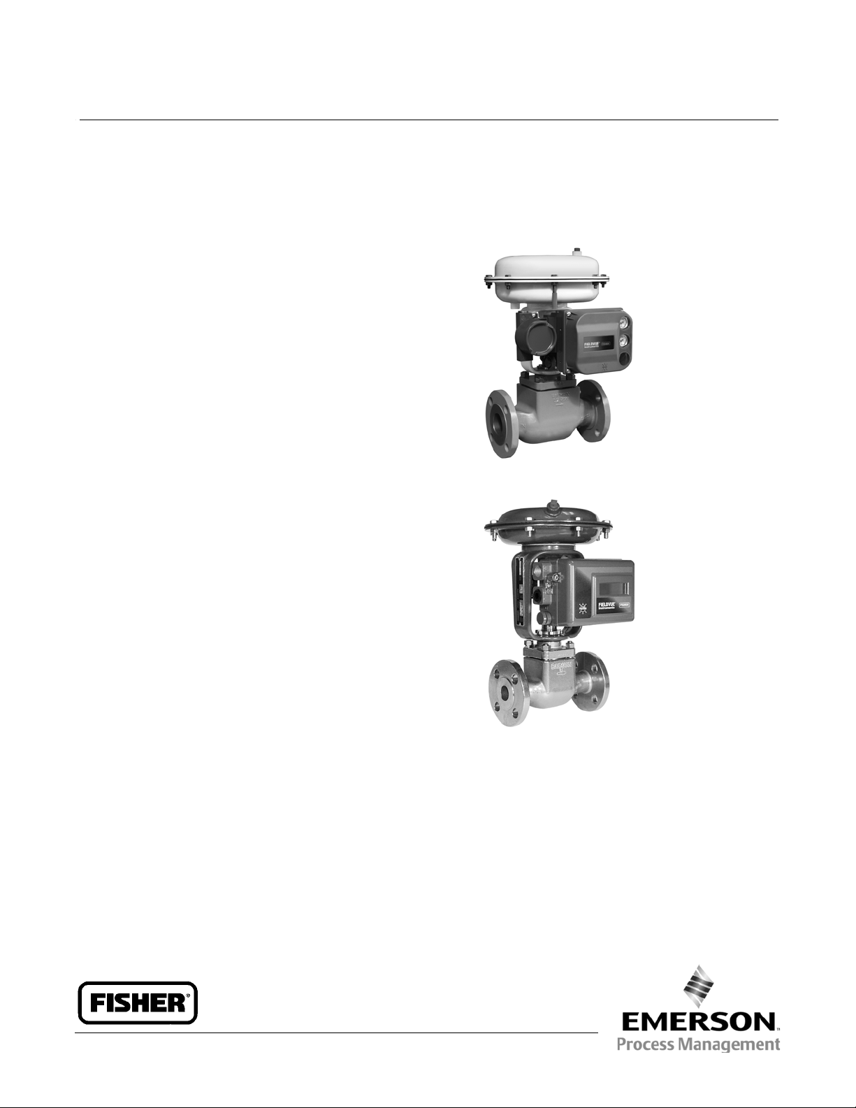
Baumann™ 24000CVF Carbon & 24000SVF
Stainless Steel Flanged Control Valves
The Baumann 24000CVF and 24000SVF line of control
valves can be utilized for the control of pressure,
temperature, level, and flow. These valves are available
with ASME CL150 RF, CL300 RF, or PN 10-40 flanged
end connections. The high performance 24000CVF
and SVF designs feature low deadband and hysteresis,
high flow capacity, superb control characteristics, tight
shutoff and advanced packing systems to meet
demanding service conditions. Compact and light
weight make them ideal for installation in high density
piping systems where space is a premium.
W9745-1
Baumann 24000CVF Control Valve with
Features
FIELDVUE DVC6200 Digital Valve Controller
Compactandlightweightdesign reduces installed
piping costs
ASME and EN end connection options to meet your
piping standards
Full lift post-guided contoured plug allows flushing
of debris through valve body
S31600 austenitic stainless steel trim material is
standard; S41600 stainless steel trim is available
Multiple trim options are available to meet changing
process requirements
Epoxy powder-coated actuator with stainless steel
fasteners provides corrosion resistance
Multi-spring field-reversible actuator with reduced
deadband permits direct operation from remote
signal devices
Fisherr FIELDVUEt digital valve controller available
for remote calibration and diagnostics in facilities
utilizing the PlantWebt architecture
W9746
Baumann 24000SVF Control Valve with
FIELDVUE DVC2000 Digital Valve Controller
ENVIRO-SEALt packing available for increased
packing life and integrity
NOLEEK bellows bonnet suitable for a wide range of
operating temperatures
Extension bonnets in multiple lengths available for
elevated temperature and cryogenic application
service
www.Fisher.com
Page 2
Product Bulletin
52.1:24CVF_SVF
March 2013
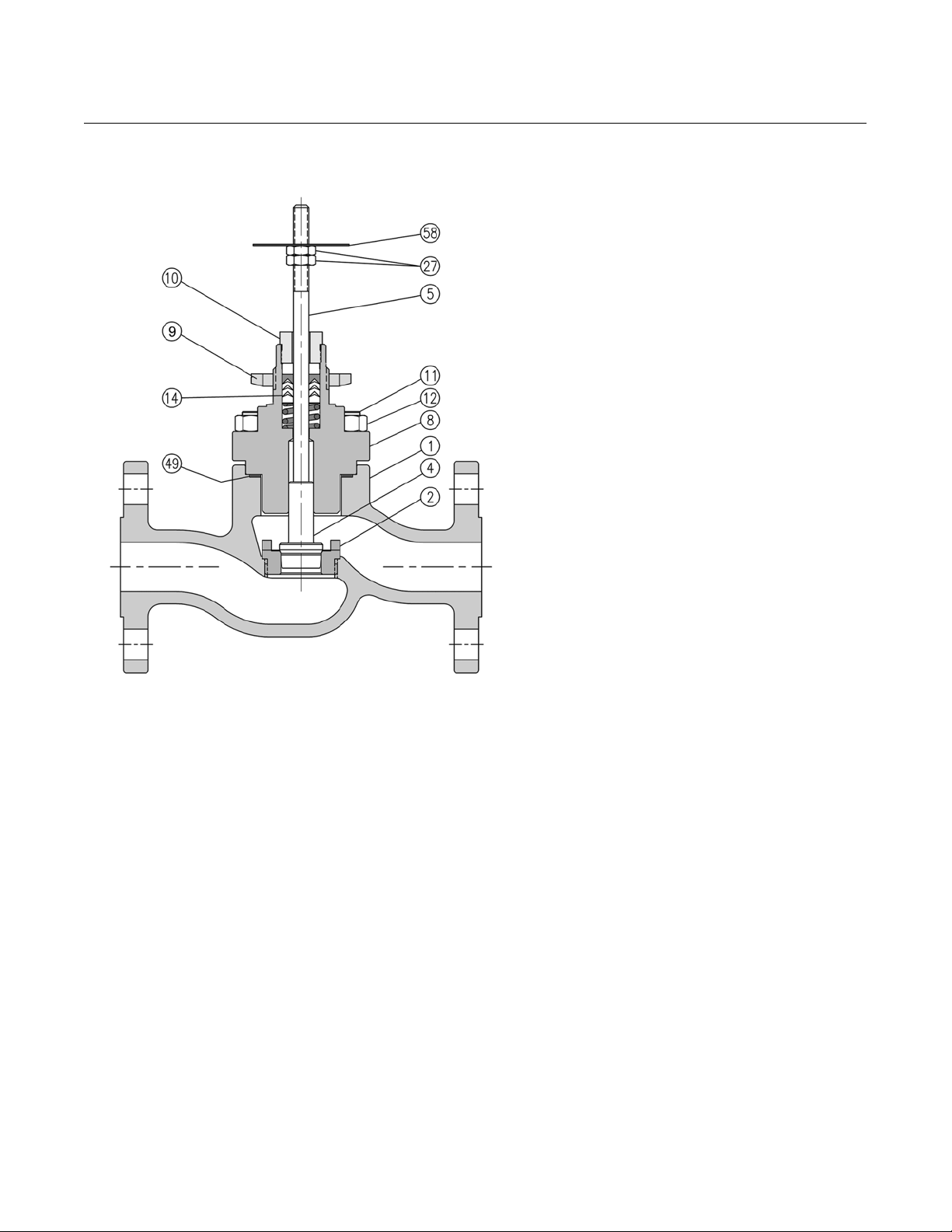
Figure 1. Baumann 24000CVF / SVF Control Valve Subassembly
24000CVF and 24000SVF Valves
D103333X012
E1245
2
Page 3
24000CVF and 24000SVF Valves
D103333X012
Table 1. Materials of Construction
Key
No.
1
Seat Ring (For Low Flow Trim, Refer
2
4
5 Stem ASTM A276S31600
8
8a Bonnet Bushing
9 Drive Nut (Yoke) S30400
10 Packing Follower ASTM A276S31600/S31603 Dual Certified
11 Stud ASME SA193 Grade B8, Class 1
12 Nut ASME SA194 Grade 8
14
27 Locknuts Stainless Steel (18-8 SST)
49 Body Gasket Graphite Grade GHR with S31600 Insert
58 Travel Indicator ASME SA240 S30400
1. Extension bonnetsand NOLEEK bellows bonnets are available with 24000SVF stainless steel valves only.
2. Guide bushing is applicable to 24000CVF carbon steel valve assembly o nly.
Description Material
Valve Body, Carbon Steel Cast CarbonSteel (ASME SA216WCC and EN10213 1.0619 Dual Certified)
Valve Body, Stainless Steel ASME SA351 CF3M
to tables 2 & 3)
Plug (Metal Seat) Cv < 2.5 ASME SA479 S21800 (standard)/ ASTM A582 S41600 Condition T (optional)
Plug (Metal Seat) Cv > 4.0 ASTM A276 S31600/ S31603(standard)/ ASTM A582 S41600 Condition T (optional)
Plug (Soft Seat) ASTM A276 S31600/ S31603with PTFE (Polytetrafluoroethylene)insert
Bonnet, Carbon Steel (Std) Cast CarbonSteel (ASME SA216WCC and EN10213 1.0619 Dual Certified)
Bonnet, Stainless Steel (Std) ASME SA351 CF3M
Bonnet (extended)
Bonnet (NOLEEK)
V-Ring Packing(standard) Refer to figure 4, table 4
Packing (optional) Refer to figures 5 & 6, tables 5 & 6
(1)
(1)
(2)
Standard ASTM A276 S31600/ S31603 Dual Certified /
Optional ASTM A582 S41600Condition T
ASME SA351 CF3M
ASME SA351 CF3M & ASTM A479 S31600/S31603, Annealed
ASTM A276 S44004, HT 56-60 HRC
Product Bulletin
52.1:24CVF_SVF
March 2013
3
Page 4
Product Bulletin
52.1:24CVF_SVF
March 2013
24000CVF and 24000SVF Valves
D103333X012
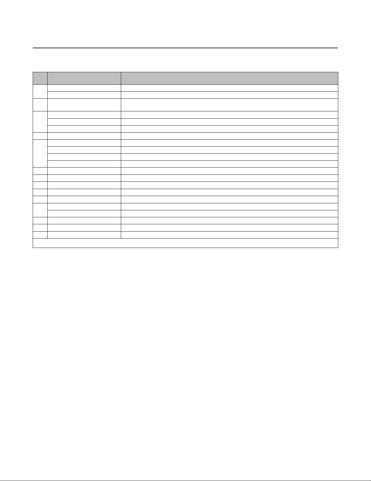
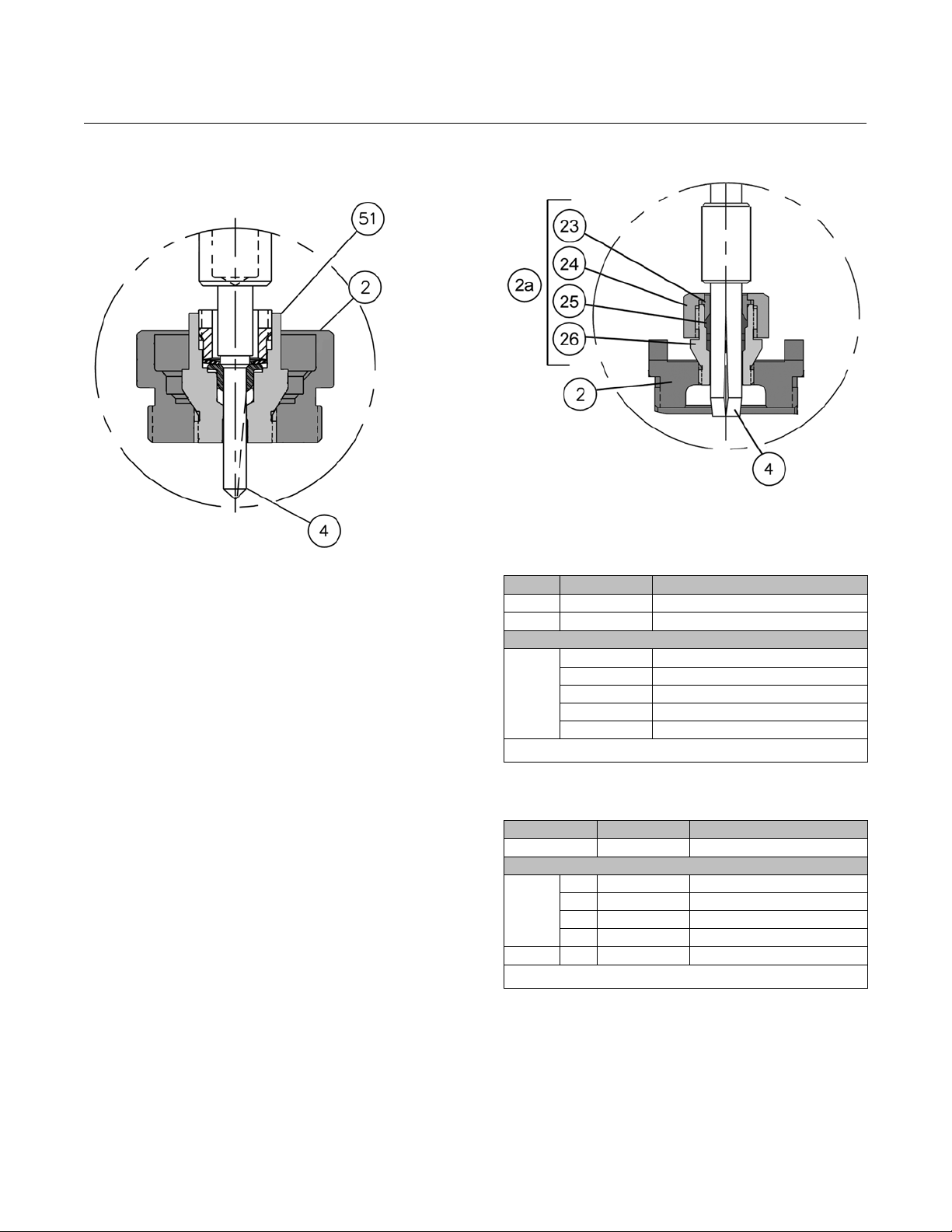
Figure 2. Optional 151 Low Flow Trim Assembly
E1246
151LowFlowTrim
Assembly
The PTFE seat surrounds the valve plug (key 4) to
eliminate clearance flow typical of lapped-in
metal-to-metal close clearance micro trims. Flow is
directed over the valve plugandforcedthrougha
single V-notch path as the plug moves above the PTFE
seat providing precise and predictable control over its
entire travel range. When the V-notch moves below
the PTFE seat, CLVI primary shutoff is achieved.
A live-loaded metal collar fully retains the PTFE seat.
The valve plug (key 4) seats against the metal collar
providing CL IV secondary shutoff. In addition, the fluid
process pressure combines with the actuator seating
force to form a hydraulic seal within the fully retained
PTFE seat. Therefore, the higher the process pressure
thetightertheshutoff.
Figure 3. Optional 177 Low Flow Trim Assembly
E1247
Table 2. 151 Low Flow Trim
Key No. Description Material
(1)
2
(1)
4
(1)
51
1. For optional trim materials, consult your Emerson Process Management salesoffice
for price and delivery.
Seat Ring ASTM A276 S31600/ S31603
Plug ASME SA479 S21800
Seat Subassembly
Cage ASTM A276 S31600/ S31603
Seat PTFE
Collar ASTM A276 S31600/ S31603
Washer ASTM A276 S31600 Cond B
Insert ASTM A276 S31600/ S31603
Table 3. 177 Low Flow Trim
Key No. Description Material
(1)
2
23 Gland ASTM A276S31600/ S31603
24 Retainer Nut ASTM A276S31600/ S31603
(1)
2a
4
1. For optional trim materials, consult your Emerson Process Management salesoffice
for price and delivery. Baumann32 actuator requires duel-stops with 177 trim series.
25 Insert ReinforcedPTFE
26 Housing ASTM A276S31600/ S31603
(1)
Seat Ring ASTM A276S31600/ S31603
Seat Subassembly
Plug ASME SA479 S21800
4
Page 5
24000CVF and 24000SVF Valves
D103333X012
Product Bulletin
52.1:24CVF_SVF
March 2013
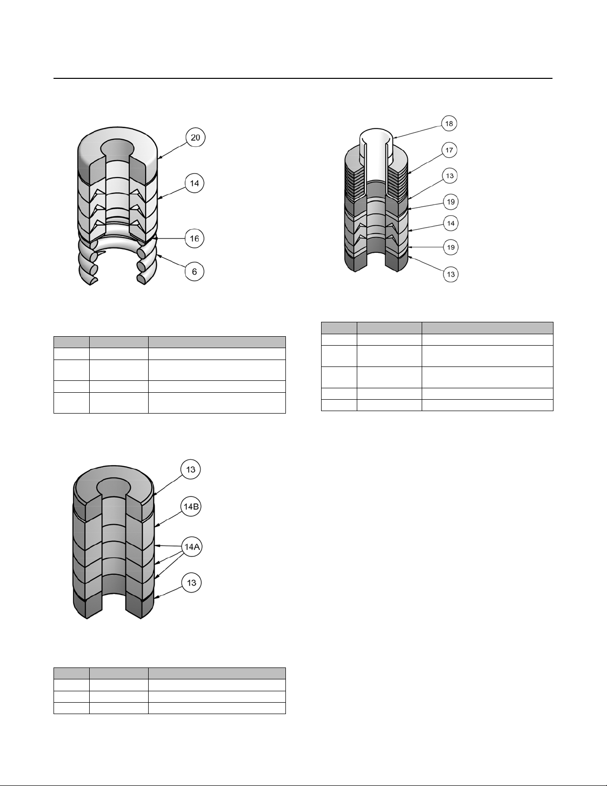
Figure 4. Standard Spring-Loaded PTFE V-Ring
Packing Kit
E1240
Table 4. Standard Spring-Loaded PTFE V-Ring
Packing Kit
Key No. Description Material
6 Spring ASTM A313S30200
14 Packing Set
16 Washer ASME SA240 S31600
20 Spacer
PTFE (Polytetrafluoroethylene) / PTFE,
25% carbonfilled
J-2000
(filled-Polytetrafluoroethylene)
Figure 6. ENVIRO-SEAL Packing Kit (Optional)
E1248
Table 6. ENVIRO-SEAL Packing Kit (Optional)
Key No. Description Material
13 Bushings Carbon Graphite
14 Packing Set
17 Belleville Spring
18 Bushing PEEK (Polyetheretherketone)
19 Washer Modified PTFE
PTFE (Polytetrafluoroethylene) / PTFE,
25% carbonfilled
N06600 NickelAlloy (ASTMB637
N07718, 40 HRC max)
Figure 5. Molded Graphite (Flexible Graphite)
Packing Kit (Optional)
E1241
Table 5. Molded Graphite (Flexible Graphite) Packing
Kit (Optional)
Key No. Description Material
13 Bushings Carbon - Graphite
14A Packing Rings Graphite
14B Packing Ring Graphite
Special ENVIRO-SEAL
Packing Note
The ENVIRO-SEAL PTFE packing system is suitable for
100 ppm environmental applications on services up to
51.7 barg (750 psig) and process temperatures
ranging from -46 to 232_C(-50to450_F).
For non-environmental applications, this packing
system offers excellent performance at the same
temperature range up to the maximum valve working
pressure.
Temperature limits apply to packing arrangements
only. Complete valve assembly temperature limits may
differ. Refer to appropriate pressure/ temperature
ratings.
Reference Fisher Packing Selection Guidelines for
Sliding-Stem Valves, bulletin 59.1:062, D101986X012.
5
Page 6
Product Bulletin
52.1:24CVF_SVF
March 2013
24000CVF and 24000SVF Valves
D103333X012
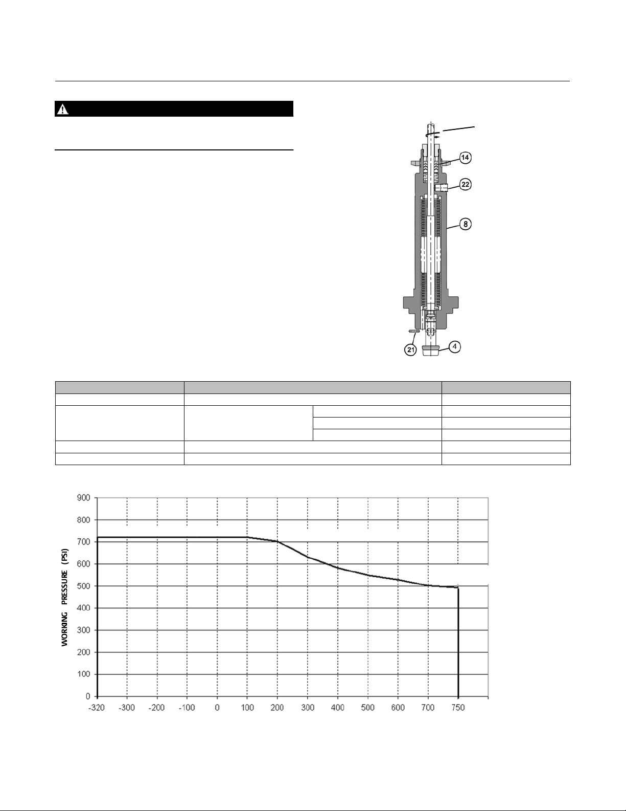
WARNING
The Baumann NOLEEK valve bonnet assembly is not
intended for use in lethal service applications.
The NOLEEK Bellows Bonnet Assembly is reliable and
user-friendly. Typical service life is in excess of 250,000
full cycles under 100 psi pressure. The bonnet adds
only approximately 5 inches to the height of a
standard valve. Operating temperature range is -195
to 399_C(-320to750_F).
ONLY AVAILABLE WITH 24000SVF STAINLESS STEEL
VALVES.
Table 7. Baumann NOLEEK Bellow Bonnet Assembly
Key Number Description Material
4 Plug Refer to table 1
8 Bellows Bonnet Sub-Assembly
21 Plug Retaining Pin S30300
22 HexSocketPipePlug,1/8NPT S30400
Figure 7. Baumann NOLEEK Bellow Bonnet Assembly
UNLIMITED STEM
ROTATION WITHOUT
TWISTING BELLOWS
BACKUP PACKING
SYSTEM (SEE PACKING
DETAIL ON PAGE 5)
TELL-TALE
CONNECTION
(1/8 NPT)
BELLOWS HOUSING
TIME PROVEN
DOUBLE WALLED
BELLOW MADE
FROM S31600,
RATED FOR UP TO
49.7 BAR (720 PSI)
PRESSURE
E1249
Housing S31600/S31603
Bellows S31603/1.4571 SST
Bonnet CF3M
Full extension provides
heat dissipation, ideal
for heattransfer fluids.
Figure 8. Bellows Pressure / Temperature Curve
49.7 barg@ -195_C (720 psig @ -320_F)
TEMPERATURE (_F)
6
48.5 barg@ 93_C(703.25 psig @ 200_F)
33.9 barg @ 398_C
(491.6 psig@ 750_F)
Page 7

Product Bulletin
24000CVF and 24000SVF Valves
D103333X012
Table 8. Cv Values at 100% Plug Opening (Kv = 0.86 x Cv)
VALVE SIZE
NPS inch inch Cv Cv Cv Cv Cv Cv Cv
1/2
3/4
1
1/2 0.8125 0.50 --- --- --- 4, 6 4.7, 6.7 5 4, 6
3/4 0.8125 0.50 --- --- --- 4, 7.5 4.7, 10 5 4, 8
1
1-1/2
2
ORIFICE
DIAMETER
0.156 0.50 ---
0.25 0.50
0.3125 0.50 --- ---
0.375 0.50 --- --- --- 1.0, 1.5 2.5 1.5 2.5
0.8125 0.50 --- --- --- 4, 8.5 4.7, 10 5 4, 9
1.0625 0.50 --- --- --- 13 15.5 --- 13
1.25 0.75 --- --- --- 20 10, 20 20 10, 20
1.5 0.75 --- --- --- 10, 17, 28 10, 17, 32.7 10, 17 10, 17, 28
1.5 0.75 --- --- --- 10, 17, 28 10, 17, 32.7 10, 17 10, 17, 28
2.0 0.75 --- --- --- 30 53.7 30, 50 30, 50
PLUG
TRAVEL
102 151 177 577 548 /588 677 648 / 688
0.00013
0.00025
0.0005
0.001
0.002
0.02, 0.05
0.10, 0.20
0.004
0.008
0.015
0.03
0.06
0.10
0.20
0.45
--- --- ---
--- --- --- --- ---
0.0005
0.001, 0.002
0.005, 0.01
0.02, 0.05
PLUG SERIES
0.22, 0.61
1.0
--- --- --- ---
52.1:24CVF_SVF
---
0.1, 0.2,0.5
1.0, 2.5
March 2013
0.5
1.0
1.5
2.5
Figure 9. Baumann 24000CVF / SVF Trims
102 Linear
LowFlowTrim
W9747
151 Modified Equal %
LowFlowTrim
W9751 W9748 W9749
177 Modified Equal %
LowFlowTrim
548 / 577 / 588
Equal % Trim
648 / 677 / 688
Linear Trim
W9750
7
Page 8

Product Bulletin
52.1:24CVF_SVF
March 2013
Table 9. ISA Sizing Coefficients
Series Cv Rating FL Fd XT KC
102
151
177
577
548/588
0.02
0.05
0.10
0.20
0.00013
0.00025
0.0005
0.001
0.002
0.004
0.008
0.015
0.03
0.06
0.10
0.20
0.45
0.0005
0.001
0.002
0.005
0.01
0.02
0.05
1
1.5
2.5
4
6
7.5
8.5
10
13
17
20
28
30
0.22
0.61
1
1.5
2.5
4.7
6.7
10
15.5
20
17
32.7
53.7
0.95
0.98
0.95 0.7 0.76 0.86
0.9
0.98 0.28 0.81 0.94
0.9
0.06
0.09
0.013
0.18
0.35
0.04
0.05
0.06
0.075
0.1
0.11
0.15
0.18
0.22
0.25
0.3
0.4
0.40
0.33
0.42
0.46
0.4
0.33
0.46
0.46
24000CVF and 24000SVF Valves
0.76 0.86
0.81 0.94
0.68 0.73
0.68 0.73
D103333X012
8
Page 9

24000CVF and 24000SVF Valves
D103333X012
Table 9. ISA Sizing Coefficients (continued)
Series Cv Rating FL Fd XT KC
677
648/688
0.1
0.2
0.5
2.5
10
17
20
30
50
0.5
1.5
2.5
10
13
20
28
30
50
1
5
1
4
6
8
9
0.9
0.9
0.08
0.12
0.19
0.27
0.68 0.73
0.46
0.4
0.33
0.42
0.68 0.73
0.46
Product Bulletin
52.1:24CVF_SVF
March 2013
Table 10. Technical Specifications
VALVE TYPE EN ASME
NOMINAL PIPE SIZE DN 15, 20, 25, 40, & 50 NPS1/2,3/4,1,1-1/2,&2
END CONNECTIONS PN 10-40 Flanges perEN 1092-1
PRESSURE RATING PN 40per EN 1092-1 CL150 or CL300 per ASMEB16.34
FACE-TO-FACE DIMENSIONS Consistent with EN 558-1 Consistent with EN 588-2 (ISA S75.03)
CL150 RF or CL300 RF Flanges per
ASME B16.5
9
Page 10

Product Bulletin
52.1:24CVF_SVF
March 2013
24000CVF and 24000SVF Valves
D103333X012
Table 11. Temperature Ratings for Packing and Seat Material
PTFE Soft Seat
SEATING MATERIAL
PACKING AND BONNET
COMBINATIONS
CHARACTERISTIC Equal Percentage or Linear
1. Temperature limitsapply to seating or packing arrangements only. Completevalve assembly temperature limits may differ, refer to appropriate pressure/temperature ratings.For
more information on packing selection, reference Fisher Packing Selection Guidelines for Sliding-StemValves, Bulletin 59.1:062 (D101986X012).
2. Extension bonnetsand NOLEEK bellows bonnets areapplicable for the 24000SVF stainless steelbody assembly ONLY.
3. PTFE packing can beus ed in cryogenic service but becomes stiff.
Reinforced PTFE 177 Trim -73 to 232_C (-100 to 450_F)
Metal Seat 102, 548, 588, 648, 688 Trim -195 to 537_C (-320 to 1000_F)
BONNET STYLE PACKING TEMPERATURE LIMIT
Standard Bonnet
Extension Bonnet
Bellows
(2, 3)
(2)
(1)
151 Trim -29 to 177_C(-20to350_F)
577 & 677 Trim -73 to 232_C(-100 to 450_F)
Spring Loaded PTFE -73 to 232_C (-100 to 450_F)
ENVIRO-SEAL -46 to232_C(-50to450_F)
Graphite -73 to 232_C (-100 to 450_F)
Spring Loaded PTFE -195 to 232_C (-320 to 450_F)
ENVIRO-SEAL -46 to232_C(-50to450_F)
Graphite -195 to537_C (-320 to 1000_F)
NOLEEK Bellows -195 to399_C (-320 to 750_F)
Table 12. Actuator Specifications
TYPE 32,54, 70 Multi-Spring Diaphragm (Single Acting)
DIAPHRAGM AREA 210, 350, 450 cm2/ 32, 54, 70 in
AIR FAILURE 32 and 54 Fails Open or Closed (Field Reversible) / 70 Fails Closed ONLY
TRAVEL 12.7or 19.1 mm / 0.50 or 0.75 inches
AMBIENT TEMPERATURE RANGE -29_Cto71_C/-20_F to 160_F
MAXIMUM AIRPRESSURE 2.4 barg / 35 psig
DIAPHRAGM MATERIAL
SPRING CASES Steel, Powder Epoxy-Coated with Stainless Steel Fasteners
YOKE Ductile Iron, Powder Epoxy-Coated
1. Optional reinforced VMQ(Silicone) diaphragm with FKM(Fluorocarbon) O-ring actuator stem seal for high temperature conditions (-29_Cto121_C/-20_F to 250_F) is available with
Baumann 32 and 54 actuators ONLY.
(1)
NBR (Nitrile) / TPES (Polyester Thermoplastic)
2
10
Page 11

24000CVF and 24000SVF Valves
D103333X012
Figure 10. Baumann 24000CVF Carbon Steel Flanges, Pressure-Temperature Ratings
ASME B16.34 A216 WCC
900
Product Bulletin
52.1:24CVF_SVF
March 2013
E1251-1
800
700
600
500
400
Pressure (psig)
300
200
100
750 psig @ -20°F
Class 300
290 psig @ -20°F
Class 150
0
-50 0 50 100 150 200 250 300 350 400 450 500
750 psig @ 200°F
260 psig @ 200°F
Temperat ur e ( ° F)
685 psig @ 450°F
185 psig @ 450°F
ASME B16.34 A216 WCC
60
50
51.7 barg @ -29°C
Class 300
51.5 barg @ 100°C
47.1 barg @ 232°C
E1252-1
40
30
19.8 barg @ -29°C
Pressu re (bar g )
20
Cl ass 150
17.7 barg @ 100°C
12.7 barg @ 232°C
10
0
-50 0 50 100 150 200 250
Temperature (°C)
11
Page 12

Product Bulletin
52.1:24CVF_SVF
March 2013
Figure 11. Baumann 24000SVF Stainless Steel Flanges, Pressure-Temperature Ratings
ASME B16.34 A351 CF3M
800
720 psi g @ -320° F
700
Class 300
600
450 psi g @ 600°F
500
400
24000CVF and 24000SVF Valves
365 psi g @ 10 00°F
D103333X012
E1254-1
300
Pressu r e (psig)
200
275 psi g @ -320 F
Class 150
140 psi g @ 600 F
20 psi g @ 1 000 F
100
0
-400 -300 -200 -100 0 100 200 300 400 500 600 700 800 900 1000 1100
Temperature (°F)
ASME B16.34 A 351 G r. CF3M
60
50
40
30
Pressure (bar g)
20
10
49.6 barg @ -195°C
Class 30 0
19 barg @ -195°C
Class 15 0
31.6 barg @ 300°C
25.2 barg @ 538°C
10.2 barg @ 300°C
1.4 barg @ 538°C
12
0
-250 -200 -150 -100 -50 0 50 100 150 200 250 300 350 400 450 500 550 600
Temperature (°C)
E1255-1
Page 13

24000CVF and 24000SVF Valves
D103333X012
Figure 12. Baumann 24000CVF and 24000SVF Pressure-Temperature Ratings for EN 1092-1
EN1092-1 ASTM A216 WCC
Product Bulletin
52.1:24CVF_SVF
March 2013
E1253-1
45
40 barg @ 0°C
40
35
30
25
20
15
10
Working Pressure (barg)
5
0
-50 0 50 100 150 200 250
PN 40
31.4 barg @ 232°C
Temperature (°C)
24000CVF
EN 1092-1 ASTM A351 CF3M
45
40
35
40 barg @ 0°C
PN 40
E1256-1
30
24.3 barg @ 500°C
25
20
15
Working Pressu re (barg)
10
5
0
-50 50 150 250 350 450 550
Temperature (°C)
24000SVF
13
Page 14

Product Bulletin
52.1:24CVF_SVF
March 2013
Table 13. Allowable Pressure Drops (bar). Do not exceed valve body temperature pressure ratings.
AIR-TO-OPEN ACTION AIR-TO-CLOSE ACTION
0.2-1.0 barg SIGNAL
ORIFICE
DIA.
(mm)
PLUG
TRAVEL
(mm)
ACT
TYPE
BENCH
RANGE
(barg)
TO ACTUATOR
Max CL
IV
Shutoff
Press.
Max CL
VI
Shutoff
Press.
4.0 12.7 32 0.3-1.0 51.7 --- 51.7
6.3 12.7 32 0.3-1.0 51.7 --- 51.7
7.9 12.7 32 0.3-1.0 --- 28.8 --- 51.7
9.5 12.7 32 0.3-1.0 31.2 19.2 51.7
32 0.3-1.0 7.79 1.31 15.6 9.10 0.2-0.9 7.79 1.31 27.3 20.8
32 0.5-1.0 15.6 9.10 23.4 16.9 0.2-0.7 19.5 13.0 39.0 32.5
20.6 12.7
54 0.3-1.0 5.93 --- 17.7 11.2 0.2-0.9 11.8 5.30 41.4 34.8
54 0.5-1.0 23.6 17.0 35.4 28.9 0.2-0.7 29.5 23.0 51.7
54 0.6-1.0 35.4 28.9 47.2 40.7 --- --- --- --- --32 0.3-1.0 4.19 --- 9.45 4.27 0.2-0.9 4.69 --- 16.5 11.4
32 0.5-1.0 9.45 4.27 14.1 8.96 0.2-0.7 11.8 6.62 23.6 18.4
27.0 12.7
54 0.3-1.0 3.59 --- 10.7 12.5 0.2-0.9 7.17 2.0 25.0 19.9
54 0.5-1.0 14.3 9.10 21.4 16.3 0.2-0.7 17.9 12.7 35.7 30.5
54 0.6-1.0 21.4 16.3 28.5 23.4 --- --- --- --- --32 0.3-1.0 3.45 --- 6.96 2.48 0.2-0.9 3.45 --- 12.1 7.65
32 --- --- --- --- --- 0.2-0.7 8.69 4.20 17.3 12.9
31.8 19.1
54 0.3-1.0 5.24 --- 10.5 6.07 0.2-0.9 5.24 --- 18.3 13.9
54 0.5-0.9 10.9 6.07 15.7 11.3 0.2-0.7 13.1 8.69 26.3 21.8
54 0.7-1.0 18.3 13.9 23.6 19.2 --- --- --- --- --70 0.7-1.0 24.9 20.5 32.1 27.6 --- --- --- --- --32 0.3-1.0 2.14 --- 4.89 1.10 0.2-0.9 2.41 --- 8.55 4.76
32 --- --- --- --- --- 0.2-0.7 6.13 2.34 12.2 8.48
54 0.3-1.0 3.72 --- 7.38 3.65 0.2-0.9 3.72 --- 19.9 9.17
38.1 19.1
54 0.5-0.9 7.38 3.65 11.1 7.31 0.2-0.7 9.24 5.52 18.5 14.8
54 0.7-1.0 12.9 9.17 16.7 12.9 --- --- --- --- --70 0.7-1.0 17.7 13.9 22.7 18.9 --- --- --- --- --70 0.8-1.2 --- --- 27.7 23.9 --- --- --- --- --32 0.3-1.0 1.38 --- 2.83 --- 0.2-0.9 1.38 --- 4.89 2.0
32 --- --- --- --- --- 0.2-0.7 3.52 --- 7.03 4.14
54 0.3-1.0 2.14 --- 4.27 1.38 0.2-0.9 2.14 --- 7.44 4.55
50.8 19.1
54 0.5-0.9 4.27 1.38 6.34 3.52 0.2-0.7 5.31 2.41 10.6 7.72
54 0.7-1.0 7.45 4.55 9.58 6.69 --- --- --- --- --70 0.7-1.0 10.1 7.24 13.0 8.07 --- --- --- --- --70 0.8-1.2 --- --- 15.9 13.0 --- --- --- --- ---
1. The maximum shutoff pressure when using ENVIRO-SEAL packing is definedby: nP = TableValue - [1112/(Port Diameter)2]. These table values should not be modified by this formula and
the maximum nP of 51.7 barshould be used forENVIRO-SEAL packing.
2. The maximum shutoff pressure when using Flexible Graphite packing isdefined by: nP =Table Value - [5337/(PortDiameter)
and the maximum nP o f 51.7 bar shouldbe used for FlexibleGraphite packing.
WITH POSITIONER
1.38 bargAIR
SUPPLY
Max CL
IV
Shutoff
Press.
Max CL
VI
Shutoff
Press.
(1)
(1)
(1)
--- 0.2-0.9 51.7 --- 51.7
--- 0.2-0.9 51.7 --- 51.7
(1,2)
50.3 0.2-0.9 31.2 19.2 51.7
24000CVF and 24000SVF Valves
D103333X012
0.2-1.0 barg SIGNAL
BENCH
RANGE
(barg)
TO ACTUATOR
Max CL
IV
Shutoff
Press.
Max CL
VI
Shutoff
Press.
0.2-0.9 --- 28.8 --- 51.7
2
]. These table values should not be modified by this formula
WITH POSITIONER
1.38 barg AIR
SUPPLY
Max CL
IV
Shutoff
Press.
(1,2)
(1,2)
(1,2)
(1)
Max CL
VI
Shutoff
Press.
---
---
(1,2)
(1)
51.7
(1)
51.7
14
Page 15

Product Bulletin
24000CVF and 24000SVF Valves
D103333X012
Table 14. Allowable Pressure Drops (psi). Do not exceed valve body temperature pressure ratings.
AIR-TO-OPEN ACTION AIR-TO-CLOSE ACTION
3-15 psig SIGNAL TO
ORIFICE
DIA. (in)
PLUG
TRAVEL
(in)
ACT
TYPE
BENCH
RANGE
(psig)
ACTUATOR
Max CL
IV
Shutoff
Press.
Max CL
VI
Shutoff
Press.
0.156 0.50 32 5-15 750 --- 750
0.25 0.50 32 5-15 750 --- 750
0.3125 0.50 32 5-15 --- 418 --- 750
0.375 0.50 32 5-15 452 278 750
32 5-15 113 19 226 132 3-13 113 19 396 301
32 7-15 226 132 339 245 3-10 283 188 565 471
0.8125 0.50
54 4-15 86 --- 257 162 3-13 171 77 600 505
54 7-15 343 248 514 419 3-10 428 334 750
54 9-15 514 419 685 591 --- --- --- --- --32 5-15 68 --- 137 62 3-13 68 --- 239 165
32 7-15 137 62 205 130 3-10 171 96 342 267
1.0625 0.50
54 4-15 52 --- 155 81 3-13 104 29 363 288
54 7-15 207 132 311 236 3-10 259 184 518 443
54 9-15 311 236 414 340 --- --- --- --- --32 5-15 50 --- 101 36 3-13 50 --- 176 111
32 --- --- --- --- --- 3-10 126 61 251 187
1.25 0.75
54 5-15 76 --- 152 88 3-13 76 --- 266 202
54 7-13 152 88 228 164 3-10 190 126 381 316
54 10-14 266 202 343 278 --- --- --- --- --70 10-15 362 297 466 401 --- --- --- --- --32 5-15 35 --- 71 16 3-13 35 --- 124 69
32 --- --- --- --- --- 3-10 89 34 177 123
54 5-15 54 --- 107 53 3-13 54 --- 188 133
1.5 0.75
54 7-13 107 53 161 106 3-10 134 80 269 214
54 10-14 188 133 242 187 --- --- --- --- --70 10-15 256 201 329 274 --- --- --- --- --70 12-18 --- --- 402 347 --- --- --- --- --32 5-15 20 --- 41 --- 3-13 20 --- 71 29
32 --- --- --- --- --- 3-10 51 --- 102 60
54 5-15 31 --- 62 20 3-13 31 --- 108 66
2.0 0.75
54 7-13 62 20 92 51 3-10 77 35 154 112
54 10-14 108 66 139 97 --- --- --- --- --70 10-15 147 105 189 147 --- --- --- --- --70 12-18 --- --- 230 189 --- --- --- --- ---
1. The maximum shutoff pressure when using ENVIRO-SEAL packing is definedby: nP = TableValue - [25/(Port Diameter)2]. These table values should not be modified by this formula and the
maximum nP of 750 psi should be usedfor ENVIRO-SEAL packing.
2. The maximum shutoff pressure when using Flexible Graphite packing isdefined by: nP =Table Value - [120/(PortDiameter)
the maximum nP of 750 psishould be used for Flexible Graphite packing.
WITH POSITIONER
20 psigAIR SUPPLY
Max CL
Shutoff
Press.
Max CL
IV
VI
Shutoff
Press.
(1)
(1)
(1)
--- 3-13 750 --- 750
--- 3-13 750 --- 750
(1,2)
730 3-13 452 278 750
3-15 psig SIGNAL TO
BENCH
RANGE
(psig)
ACTUATOR
Max CL
IV
Shutoff
Press.
Max CL
Shutoff
Press.
3-13 --- 418 --- 750
2
]. These table values should not be modified by this formula and
52.1:24CVF_SVF
WITH POSITIONER
20 psigAIR SUPPLY
Max CL
VI
Shutoff
Press.
March 2013
Max CL
IV
Shutoff
(1,2)
(1,2)
(1,2)
(1)
VI
Press.
---
---
(1,2)
750
750
(1)
(1)
15
Page 16

Product Bulletin
52.1:24CVF_SVF
March 2013
Figure 13. Dimensional Drawings
216
(48.5)
141
(5.5)
94
(3.7)
227
(8.9)
3660/3661
B
A
24000CVF/SVF FLANGED
WITH BAUMANN 32 ATO
ACTUATOR WITH
HANDWHEEL
216
(48.50)
31 (1.24)
POSITIONER
(OPTIONAL)
TOP-MOUNTED
HANDWHEEL
(OPTIONAL)
1/4 NPT
WITH HANDWHEEL AND DVC2000
279
(411.0)
72
(2.8)
276
(10.9)
127 (5.0)
BAUMANN 54 ATO ACTUATOR
160
(46.3)
24000CVF and 24000SVF Valves
D103333X012
333
60
(2.4)
271
(10.7)
163 (6.4)
MAX
(413.1)
BAUMANN 70 ATO
ACTUATOR WITH OPTIONAL
FIELDVUE DIGITAL VALVE
CONTROLLER
130
(5.1) MAX
229
(9.0)
3/4 INCH
SQUARE
160
(46.3)
BAUMANN 32 ACTUATOR
WITH ADJUSTABLE
OPEN / CLOSE DUAL TRAVEL
E1257
Note: Actuator removal requires 115 mm (4.5 inches) vertical clearance.
STOPS
BAUMANN 32 ATC / FAIL
OPEN ACTUATOR WITH
HANDWHEEL
BAUMANN 54 ATC / FAIL
OPEN ACTUATOR WITH
HANDWHEEL
Table 15. Valve Assembly Weights
VALVE SIZE 24000CVF WEIGHTS 24000SVF WEIGHTS
EN ASME CL150 CL300 EN 10-40 CL150 CL300 EN 10-40
DN NPS kg lb kg lb kg lb kg lb kg lb kg lb TYPE kg lb
15 1/2 3.1 6.8 3.3 8.3 3.8 7.7 3.7 7.2 3.5 8.2 3.5 7.8 32 4.5 10
20 3/4 3.3 7.3 3.4 10 4.5 9.2 4.7 7.4 4.2 10.3 4.3 9.4 54 11.3 25
25 1 4.8 10.6 5.1 13.8 6.3 12.6 6.4 11.2 5.7 14 5.9 13 70 15.4 34
40 1-1/2 8.3 18.2 8.3 24.8 11.3 21.2 11.4 18.3 9.6 25.2 9.8 21.7
50 2 14.1 31 13.8 35.3 16 33.4 16.1 30.4 15.2 35.4 15.2 33.4
16
ACTUATOR WEIGHTS
mm
(inch)
Page 17

Product Bulletin
24000CVF and 24000SVF Valves
D103333X012
Figure 14. Baumann 24000SVF Stainless Steel Control Valves with Extension Bonnets Dimensional Drawing
B
B
52.1:24CVF_SVF
March 2013
B
B
A
STANDARD BONNET
NOLEEK BELLOWS BONNET
OR SINGLE EXTENSION
E1258
Table 16. Dimensions
VALVE SIZE
EN ASME CL150 CL300 EN 10-40 Standard
DN NPS mm inch mm inch mm inch mm inch mm inch mm inch mm inch mm inch
15 1/2 184 7.25 190 7.5 130 5.11 79 3.1 216 8.5 352 13.9 488 19.2 226 8.9
20 3/4 184 7.25 194 7.62 150 5.90 79 3.1 216 8.5 352 13.9 488 19.2 226 8.9
25 1 184 7.25 197 7.75 160 6.30 84 3.3 221 8.7 356 14.0 493 19.4 229 9.0
40 1-1/2 222 8.75 235 9.25 200 7.87 96 3.8 234 9.2 370 14.6 505 19.9 229 9.0
50 2 254 10.0 267 10.5 230 9.06 107 4.2 244 9.6 381 15.0 516 20.3 234 9.2
1. Actuator requires 115 mm (4.5 inches) verticalclearance.
2. Face-to-face dimension per EN558-1 and ISA S75.03.
3. Extension and NOLEEK bellows bonnets are available with 24000SVF stainless steel body ONLY.
(1, 2)
A
FACE-TO-FACE
A
EXTENSION BONNET
BONNET
Single Double Triple
AA
DOUBLE
TRIPLE
EXTENSION BONNET
B
BONNET
Extension
(3)
NOLEEK
Bellows
(3)
17
Page 18

Product Bulletin
52.1:24CVF_SVF
March 2013
Table 17. Model Numbering System
24
Actuator
Type
32
54 151 Modified Equal % / PTFE Seat VI SVF
70 177 Modified Equal % /Reinforced PTFE VI EB Bellows
MV1020
VA1020
1. Baumann 32 actuator requires dual stops with177 trim series.
2. Refer to bulletin 52.1:ECV, Baumann Electronic Modulating Actuators, D103347X012,for details on theseelectronic actuators.
3. Only availablewith 24000SVF stainlesssteel valve bodies.
Valve Body Plug Series Characteristic
(1)
(2)
(2)
102 Linear / Metal Seat IV CVF Carbon Omit Standard
548 Equal %/ Metal Seat (S41600) IV
577 Equal % / PTFE Seat VI
588 Equal %/ Metal Seat (S31600) IV
648 Linear / Metal Seat (S41600) IV
677 Linear / PTFE Seat VI
688 Linear / Metal Seat (S31600) IV
Seat
Leakage
24000CVF and 24000SVF Valves
D103333X012
Valve Body Material Bonnet Style
Stainless
Steel
E Extended
(3)
(3)
18
Page 19

24000CVF and 24000SVF Valves
D103333X012
Product Bulletin
52.1:24CVF_SVF
March 2013
19
Page 20

Product Bulletin
52.1:24CVF_SVF
March 2013
24000CVF and 24000SVF Valves
D103333X012
Neither Emerson, Emerson Process Management, nor any of their affiliated entities assumes responsibility for the selection, use or maintenance
of anyproduct. Responsibility for properselection, use,and maintenanceof any product remains solely with thepurchaser andend user.
Baumann, Fisher, FIELDVUE, PlantWeb, and ENVIRO-SEAL are marks owned by oneof the companies in the Emerson Process Management business unit of
Emerson Electric Co. Emerson Process Management, Emerson, and the Emerson logoare trademarks and service marks of Emerson Electric Co.All other
marks arethe property oftheir respective owners.
The contents of this publication are presented for informational purposes only, and while every effort has been made to ensure their accuracy, they arenot
to be construed as warranties or guarantees, express or implied, regarding the products or services described herein or their use or applicability. All sales are
governed by our terms and conditions, which are available upon request. We reserve the right to modify or improve the designs or specifications of such
products at any time without notice.
Emerson Process Management
Marshalltown, Iowa 50158 USA
Sorocaba, 18087 Brazil
Chatham, Kent ME4 4QZ UK
Dubai, United Arab Emirates
Singapore 128461 Singapore
www.Fisher.com
E 2009, 2013 Fisher ControlsInternational LLC. All rights reserved.
20
 Loading...