

Page 1
Instruction Manual
D102005X012
846 Transducer
Fisherr 846 Current-to-Pressure Transducer
March 2015
Contents
1. Introduction
Scope of Manual 2.............................
Description 2.................................
Specifications 2...............................
Related Documents 5..........................
Educational Services 6.........................
2. Installation
Hazardous Area Classifications and Special
Instructions for Safe‐Use and Installation
in Hazardous Locations 7.....................
CSA 8....................................
FM 8.....................................
ATEX 9...................................
IECEx 10..................................
ATEX/IECEx 10............................
Mounting 11.................................
Pressure Connections 11.......................
Supply Pressure 13.........................
Output Pressure 17........................
Electrical Connections 17.......................
Venting Ports 18..............................
Signal Interruption 18..........................
3. Calibration
Standard Performance:
Full Range Input, Direct Action 21.............
Multirange Performance:
Full Range Input, Direct Action 21.............
Standard Performance:
Split Range Input, Direct Action 22.............
4 to 12 mA Input Signal 22..................
12 to 20 mA Input Signal 22.................
Standard Performance:
Full Range Input, Reverse Action 23............
Multirange Performance:
Full Range Input, Reverse Action 23............
Standard Performance:
Split Range Input, Reverse Action 24...........
4 to 12 mA Input Signal 24..................
12 to 20 mA Input Signal 24.................
Transporting the Module Final Assembly 25.......
4. Principle of Operation
Electronic Circuit 26...........................
Magnetic Actuator 27..........................
Pilot Stage 27.................................
Booster Stage 28..............................
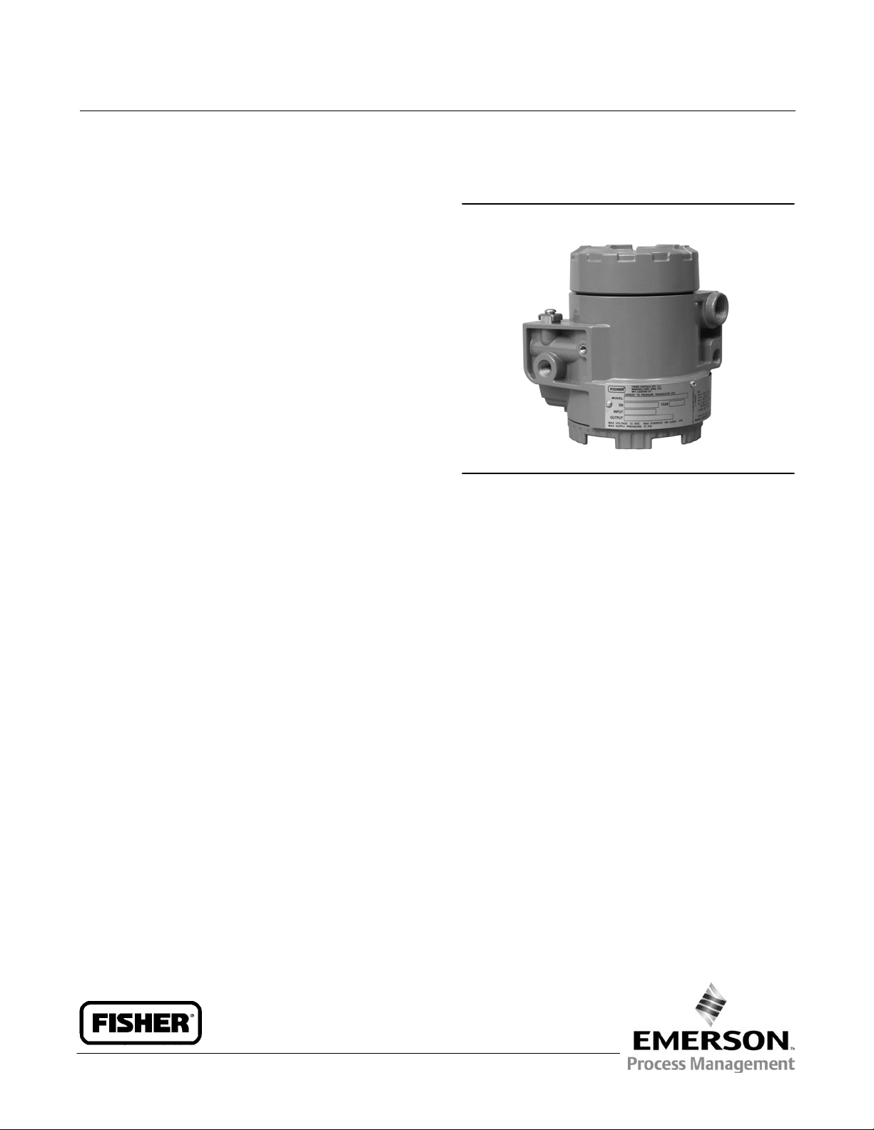
Figure 1-1. Fisher 846 Current‐to‐Pressure
Transducer
X0234
5. Troubleshooting
Diagnostic Features 29.........................
Stroke Port 29.............................
Remote Pressure Reading (RPR) 29...........
Using a Frequency Counter to read the
RPR Signal 29.........................
In‐service Troubleshooting 30...................
Troubleshooting in the Shop 33.................
6. Maintenance
Module Final Assembly 35......................
Removing the Module Final Assembly 38......
Replacing the Module Final Assembly 39.......
Electronic Circuit Board 40......................
Remote Pressure Reading (RPR) Jumper 40.....
Range Jumper 41..........................
Action 41.................................
Removing the Electronic Circuit Board 41......
Replacing the Electronic Circuit Board 42......
Pilot/Actuator Assembly 42.....................
Action 42.................................
Removing the Pilot/Actuator Assembly 43.....
Replacing the Pilot/Actuator Assembly 44.....
Module Subassembly 44........................
Terminal Compartment 44.....................
Exhaust and Stroke Port Screens 45..............
7. Parts 46....................................
8. Installation Drawings 50......................
www.Fisher.com
Page 2

846 Transducer
March 2015
Instruction Manual
D102005X012
Section 1 Introduction
Scope of Manual
This instruction manual provides installation, operating, calibration, maintenance, and parts ordering information
Fisher 846 current‐to‐pressure transducers. Refer to separate manuals for instructions covering equipment used with
the transducers.
Do not install, operate or maintain an 846 current‐to‐pressure transducer without being fully trained and qualified
in valve, actuator, and accessory installation, operation, and maintenance. To avoid personal injury or property
damage, it is important to carefully read, understand, and follow all of the contents of this manual, including
all safety cautions and warnings. If you have any questions about these instructions, contact your Emerson Process
Management sales office before proceeding.
Description
The 846 current‐to‐pressure transducer, shown in figure 1-1, accepts an electrical input signal and produces a
proportional pneumatic output. Typically, 4 to 20 mA is converted to 0.2 to 1.0 bar (3 to 15 psi). Models are available
in direct or reverse action and field‐selectable full or split range inputs. Refer to the Calibration section for more
information on input/output combinations.
The most common application of the transducer is to receive an electrical signal from a controller and produce a
pneumatic output for operating a control valve actuator or positioner. The 846 may also be used to transduce a signal
for a pneumatic receiving instrument.
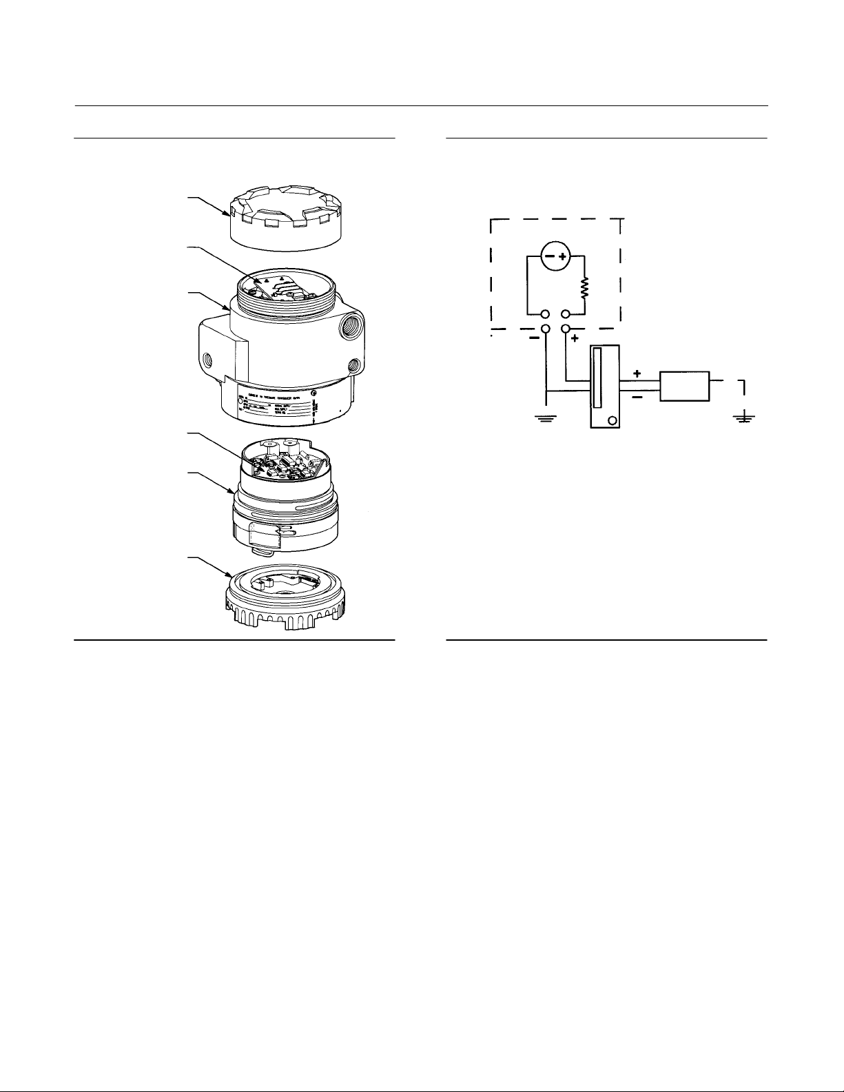
The 846 is an electronic I/P transducer. It has a single electronic circuit board, as shown in figure 1-2. The circuit
contains a solid‐state pressure sensor that monitors output pressure and is part of an electronic feedback network. The
self‐correcting ability provided by the sensor/circuit combination allows the transducer to produce a very stable and
responsive output signal.
All active mechanical and electrical components of the 846 are incorporated into a single, field‐replaceable module
called the module final assembly, shown in figure 1-2. The module final assembly contains the electronic circuit board,
pilot/actuator assembly, and booster stage. The module final assembly is easily removed by unscrewing the module
cover. Its design minimizes parts and reduces the time required for repair and troubleshooting.
The terminal compartment and module compartment are separated by a sealed compartment wall. This
multi‐compartment housing also protects the electronics from contaminants and moisture in the supply air.
Specifications
WARNING
This product is intended for a specific range of pressures, temperatures, and other application specifications. Applying
different pressure, temperature and other service conditions could result in a malfunction of the product, property damage
or personal injury.
Specifications for the 846 transducer are listed in table 1-1.
2
Page 3

Instruction Manual
D102005X012
Table 1-1. Specifications
846 Transducer
March 2015
Input Signal
Standard Performance:
4 to 20 mA DC, 4 to 12 mA DC, or 12 to 20 mA DC.
Field adjustable split ranging.
Multirange Performance:
4 to 20 mA DC. Consult factory for split range input.
Equivalent Circuit
See figure 1-3
Output Signal
(1)
Standard Performance:
(Consult factory for split range output)
Direct Action (Minimum span of 6 psi)
Typical outputs: 0.2 to 1.0 bar (3 to 15 psi).
Rangeability between 0.1 and 1.2 bar (1 and 18 psi)
Reverse Action (Minimum span of 11 psi)
Typical outputs: 1.0 to 0.2 bar (15 to 3 psi)
Rangeability between 1.2 and 0.1 bar (18 and 1 psi)
Multirange Performance:
Direct Action (Minimum span of 6 psi)
Typical outputs: 0.2 to 1.9 bar (3 to 27 psi), 0.4 to
2 bar (6 to 30 psi), and 0.3 to 1.7 bar (5 to 25 psi)
Rangeability between 0.03 and 2.3 bar (0.5 and
33 psi)
Reverse Action (Minimum span of 11 psi)
Typical outputs: 1.9 to 0.2 bar (27 to 3 psi), 2 to
0.4 bar (30 to 6 psi), and 1.7 to 0.3 bar (25 to 5 psi)
Rangeability between 2.3 and 0.03 bar (33 and
0.5 psi)
Supply Pressure
(2)
Standard Performance: 1.2 to 1.6 bar (18 to 24 psi)
Multirange Performance:
0.2 bar (3 psi)
(3)
greater than the maximum
calibrated output pressure
Maximum: 2.4 bar (35 psi)
Supply Pressure Medium
Clean, dry air
Per ISA Standard 7.0.01
A maximum 40 micrometer particle size in the air
system is acceptable. Further filtration down to 5
micrometer particle size is recommended. Lubricant
-Continued-
content is not to exceed 1 ppm weight (w/w) or
volume (v/v) basis. Condensation in the air supply
should be minimized
Per ISO 8573-1
Maximum particle density size: Class 7
Oil content: Class 3
Pressure Dew Point: Class 3 or at least 10°C less than
the lowest ambient temperature expected
Output Air Capacity
(4)
Standard: 6.4 m3/hr (240 scfh) at 1.4 bar
(20 psi) supply pressure
3
Multirange: 9.7 m
/hr (360 scfh) at 2.5 bar
(35 psig) supply pressure
Maximum Steady‐State Air Consumption
(4)
0.3 m3/hr (12 scfh) at 1.4 bar (20 psi) supply pressure
Temperature Limits
(2)
Operating: -40 to 85_C (-40 to 185_F)
Storage :-40 to 93_C (-40 to 200_F)
Humidity Limits
0 to 100% condensing relative humidity
Performance
(5)
Note: The performance of all 846 I/Ps is verified
using computer automated manufacturing systems
to ensure that every unit shipped meets its
performance specifications.
Linearity, Hysteresis, and Repeatability: $0.3% of
span.
Temperature Effect (total effect including zero and
span): $0.07%/_C (0.045%/_F) of span
Vibration Effect: $0.3% of span per g during the
following conditions:
5 to 15 Hz at 4 mm constant displacement
15 to 150 Hz at 2 g. 150 to 2000 Hz at 1 g.
per SAMA Standard PMC 31.1, Sec. 5.3, Condition 3,
Steady State
Shock Effect: $0.5% of span, when tested per SAMA
Standard PMC 31.1, Sec. 5.4.
Supply Pressure Effect: Negligible
3
Page 4

846 Transducer
March 2015
Table 1-1. Specifications (continued)
Instruction Manual
D102005X012
Performance (continued)
(5)
Electromagnetic Interference (EMI): Tested per IEC
61326‐1 (Edition 1.1). Meets emission levels for Class
A equipment (industrial locations) and Class B
equipment (domestic locations). Meets immunity
requirements for industrial locations (Table A.1 in the
IEC specification document). Immunity performance
is shown in table 1-2.
Leak Sensitivity
3
4.8 m
/hr (180 scfh) downstream leakage.
(4)
: Less than 1.0% of span for up to
Overpressure Effect: Less than 0.25% of span for
misapplication of up to 7.0 bar (100 psi) supply
pressure for less than 5 minutes to the input port.
Reverse Polarity Protection:
No damage occurs from reversal of normal supply
current (4 to 20 mA) or from misapplication of up to
100 mA.
Connections
Supply Air, Output Signal, and Output Gauge:
1/4‐18 NPT internal connection
Electrical: 1/2‐14 NPT internal conduit connection
Adjustments
Zero and Span: screwdriver adjustments located in
terminal compartment.
Remote Pressure Reading (RPR)
Jumper selectable, ON or OFF, if unit includes
option
Frequency Range: 0 to 10,000 Hz
Amplitude: 0.4 to 1.0 V
p‐p
Required Operating Voltage with Remote pressure
Reading Off
Min. 6.0 V (at 4 mA)
Max. 7.2 V (at 20 mA)
Required Operating Voltage with Remote Pressure
Reading On
Min 6.4 V (at 4 mA)
Max. 8.2 V (at 20 mA)
-continued-
Electrical Classification
Hazardous area:
CSA C/US—Intrinsically Safe, Explosion-proof,
Non-Incendive
FM—Intrinsically Safe, Explosion-proof, Non-Incendive
ATEX—Intrinsically Safe, Flameproof, Type n
IECEx—Intrinsically Safe, Flameproof
Refer to Hazardous Area Classifications and Special
Instructions for “Safe Use” and Installation in
Hazardous Locations in Section 2 for additional
information
Electrical Housing:
Tropicalization (Fungus test per MIL-STD-810)
CSA C/US—Type 4X
FM—Type 4X
ATEX—IP66
IECEx—IP66
(6)
(6)
Other Classifications/Certifications
INMETRO—National Institute of Metrology, Quality,
and Technology (Brazil)
KGS—Korea Gas Safety Corporation (South Korea)
NEPSI— National Supervision and Inspection Centre
for Explosion Protection and Safety of
Instrumentation (China)
Contact your Emerson Process Management sales
office for classification/certification specific
information
Construction Materials
Housing: Low‐copper aluminum with polyurethane
paint, or 316 stainless steel
O‐Rings: Nitrile, except silicone for sensor O‐rings.
Options
Fisher 67CFR filter regulator, supply and output
gauges or tire valve remote pressure reading, module
cover with multiple stroke ports, stainless steel
housing, or stainless steel mounting bracket.
Weight
Aluminum: 2.9 kg (6.5 lb) excluding options
Stainless Steel: 6.7 kg (14.8 lb) excluding options
4
Page 5

Instruction Manual
D102005X012
Table 1-1. Specifications (continued)
846 Transducer
March 2015
Declaration of SEP
Fisher Controls International LLC declares this
product to be in compliance with Article 3 paragraph
3 of the Pressure Equipment Directive (PED) 97 / 23 /
EC. It was designed and manufactured in accordance
NOTE: Specialized instrument terms are defined in ANSI/ISA Standard 51.1 - Process Instrument Terminology.
1. Metric calibration also available.
2. The pressure/temperature limits in this document, and any applicable standard or code limitation should not be exceeded.
3. 0.14 bar (2 psi) for a 2.3 bar (33 psi) output.
4. Normal m
5. Reference Conditions: 4.0 to 20 mA DC input, 0.2 to 1.0 bar (3 to 15 psi) output, and 1.4 bar (20 psi) supply pressure.
6. ATEX and IECEx Flameproof — IP66 per CSA Letter of Attestation.
3
/hr—Normal cubic meters per hour (0_C and 1.01325 bar, absolute). Scfh—Standard cubic feet per hour (60_F and 14.7 psia).
with Sound Engineering Practice (SEP) and cannot
bear the CE marking related to PED compliance.
However, the product may bear the CE marking to
indicate compliance with other applicable European
Community Directives.
Table 1-2. EMC Immunity Performance Criteria
Port Phenomenon Basic Standard Test Level Performance Criteria
Electrostatic discharge (ESD) IEC 61000‐4‐2
Enclosure
I/O signal/control
Specification limit = ±1% of span
1. A = No degradation during testing. B = Temporary degradation during testing, but is self‐recovering.
Radiated EM field IEC 61000‐4‐3
Burst (fast transients) IEC 61000‐4‐4 1 kV A
Surge IEC 61000‐4‐5 1 kV (line to ground only, each) B
Conducted RF IEC 61000‐4‐6
4 kV contact
8 kV air
80 to 1000 MHz @ 10V/m with 1 kHz AM at 80%
1400 to 2000 MHz @ 3V/m with 1kHz AM at 80%
2000 to 2700 MHz @ 1V/m with 1kHz AM at 80%
150 kHz to 8 MHz at 3 Vrms B
8 MHz to 80 MHz at 3 Vrms A
(1)
A
A
Related Documents
This section lists other documents containing information related to the 846 transducer. These documents include:
D INMETRO Hazardous Area Approvals for Fisher 846 Current-to-Pressure Transducers Instruction Manual
(D103623X012)
D NEPSI Hazardous Area Approvals for Fisher 846 Current-to-Pressure Transducers Instruction Manual
(D103618X012)
All documents are available from your Emerson Process Management sales office. Also visit our website at
www.Fisher.com.
5
Page 6
846 Transducer
March 2015
Instruction Manual
D102005X012
Figure 1-2. Transducer Modular Construction
TERMINAL
COMPARTMENT
COVER
TERMINAL BLOCK
MODULE HOUSING
ELECTRONIC
CIRCUIT BOARD
MODULE FINAL
ASSEMBLY
Figure 1-3. Equivalent Circuit
846
6 V DC
50
OHM
S
POWER
SUPPLY
NOTE:
THE 846 IS NOT A CONSTANT RESISTOR IN SERIES WITH AN INDUCTOR. IT IS BETTER
MODELED IN THE LOOP AS A 50 OHM RESISTOR IN SERIES WITH A 6‐VOLT DC VOLTAGE
DROP WITH NEGLIGIBLE INDUCTANCE.
A6325
MODULE COVER
A6643
Educational Services
For information on available courses for the 846 current‐to‐pressure transducer, as well as a variety of other products,
contact:
Emerson Process Management
Educational Services - Registration
Phone: +1-641-754-3771 or +1-800-338-8158
Email: education@emerson.com
http://www.emersonprocess.com/education
6
Page 7

Instruction Manual
D102005X012
846 Transducer
March 2015
Section 2 Installation22
WARNING
To avoid personal injury or property damage from the sudden release of pressure or air:
D Always wear protective clothing, gloves, and eyewear when performing any installation operations.
D Disconnect any operating lines providing air pressure, electric power, or a control signal to the actuator. Be sure the
actuator cannot suddenly open or close the valve.
D Use bypass valves or completely shut off the process to isolate the valve from process pressure. Relieve process pressure
on both sides of the valve.
D Use lock‐out procedures to be sure that the above measures stay in effect while you work on the equipment.
D Check with your process or safety engineer for any additional measures that must be taken to protect against process
media.
This section presents information on installing the 846 current‐to‐pressure transducer. Figures 2-1, 2-2, 2-3, and 2-5
can be used as references for instructions contained in this section.
When a control valve is ordered with a 846 transducer specified to be mounted on the actuator, the factory‐mounted
transducer is connected to the actuator with the necessary tubing and calibrated to the specifications on the order.
If the transducer is purchased separately for mounting on a control valve already in service, all the necessary mounting
parts are furnished, if ordered. This includes the appropriate bracket for attaching the unit to an actuator boss (with
tapped holes) or for attaching it to the diaphragm casing.
If preferred, mounting parts can be supplied for mounting the transducer on a 51 mm (2‐inch) diameter pipestand, a
flat surface, or a bulkhead.
Transducers also can be ordered separately for mounting on a control valve assembly already in service. The
transducer may be ordered with or without mounting parts. Mounting parts include the appropriate bracket and bolts
for attaching the unit to an actuator boss (with tapped holes) or for attaching it to the diaphragm casing.
Hazardous Area Classifications and Special Instructions for “Safe Use” and
Installation in Hazardous Locations
Certain nameplates may carry more than one approval, and each approval may have unique installation/wiring
requirements and/or conditions of “safe use”. These special instructions for “safe use” are in addition to, and may
override, the standard installation procedures. Special instructions are listed by approval.
Note
This information supplements the nameplate markings affixed to the product.
Always refer to the nameplate itself to identify the appropriate certification. Contact your Emerson Process Management sales
office for approval/certification information not listed here.
7
Page 8

846 Transducer
March 2015
Instruction Manual
D102005X012
WARNING
Failure to follow these conditions of safe‐use could result in personal injury or property damage from fire or explosion, and
area re‐classification.
CSA
Intrinsically Safe, Explosion-proof, Non-Incendive
No special conditions for safe use.
Refer to table 2-1 for approval information.
Table 2-1. Hazardous Area Classifications for Canada—cCSAus
Certification Body Certification Obtained Entity Rating Temperature Code
Vmax = 30 VDC
Imax = 100 mA
Ci = 0.016 mF
Li = 20 mH
- - - T4 (Tamb ≤ 60_C)
T4 (Tamb ≤ 60_C)
CSA
Ex ia Intrinsically Safe
Class I Division 1 Groups A,B,C,D T4
per drawing GE59146 (see figure 8-1)
XP Explosion-proof
Class I Division 1 Groups C,D
DIP Dust Ignition-proof
Class II III Division I Groups E,F,G T4
NI Non-incendive
Class I, Division 2, Groups A,B,C,D T4
FM
Special Conditions of Use
Intrinsically Safe, Explosion-proof, Non-Incendive
1. The apparatus enclosure contains aluminum and is considered to constitute a potential risk of ignition by impact or
friction. Care must be taken into account during installation and use to prevent impact or friction.
Refer to table 2-2 for additional approval information.
Table 2-2. Hazardous Area Classification for United Stated—FM
Certification Body Certification Obtained Entity Rating Temperature Code
Vmax = 30 VDC
Imax = 100 mA
Pmax = 1.0 W
Ci = 0.016 mF
Li = 20 mH
- - - T4 (Tamb ≤ 60_C)
T4 (Tamb ≤ 60_C)
FM
IS Intrinsically Safe
Class I, II, III Division 1 Groups A,B,C,D,E,F,G
per drawing GE59147 (see figure 8-2)
XP Explosion-proof
Class I Division 1 Groups B,C,D
DIP Dust Ignition-proof
Class II, III Division I Groups EFG
NI Non-incendive
Class I Division 2 Groups A,B,C,D
8
Page 9

Instruction Manual
D102005X012
846 Transducer
March 2015
ATEX
Special Conditions for Safe Use
Intrinsically Safe
This equipment is intrinsically safe and can be used in potentially explosive atmospheres.
The apparatus must be only connected to a certified associated intrinsically safe equipment and this combination
must be compatible as regards intrinsic safety rules.
The electrical parameters of certified equipment which can be connected to the sensor must not exceed one of these
following values:
U
≤ 30 V
0
I
≤ 100 mA
0
P
≤ 1.0 W
0
Ambient temperature: -40_C to +80_C
Flameproof
Refer to page 10.
Type n
No special conditions for safe use.
Refer to table 2-3 for additional approval information.
Table 2-3. Hazardous Area Classifications—ATEX
Certificate Certification Obtained Entity Rating Temperature Code
Intrinsically Safe
II 1 GD
Gas
Ex ia IIC T4,T5 Ga
Dust
Ex ia IIIC IP66 Da T90_C (Tamb ≤ 80_C)
Ex ia IIIC IP66 Da T50_C (Tamb ≤ 40_C)
Flameproof
ATEX
II 2 G
Gas
Ex d IIB T5/T6 Gb
Type n
II 3 GD
Gas
Ex nA IIC T5/T6 Gc
Dust
Ex tc IIIC T88_C T
Ex tc IIIC T77_C T
500
500
Dc IP66
Dc IP66
Ui = 30 VDC
Ii = 100 mA
Pi = 1.0 W
Ci = 8 nF
Li = 20 mH
- - -
- - -
T4 (Tamb ≤ 80_C)
T5 (Tamb ≤ 40_C)
T5 (Tamb ≤ 80_C)
T6 (Tamb ≤ 65_C)
T5 (Tamb ≤ 85_C)
T6 (Tamb ≤ 74_C)
9
Page 10

846 Transducer
March 2015
IECEx
Special Conditions for Safe Use
Intrinsically Safe
No special conditions for safe use.
Flameproof
See below.
Refer to table 2-4 for additional approval information.
Table 2-4. Hazardous Area Classifications—IECEx
Certificate Certification Obtained Entity Rating Temperature Code
Intrinsically Safe
Gas
Ex ia IIC T4/T5 Ga
IECEx
Flameproof
Gas
Ex d IIB T5/T6 Gb
Ui = 40 VDC
Ii = 200 mA
Pi = 1.0 W
Ci = 8 nF
Li = 20 mH
- - -
Instruction Manual
D102005X012
T4 (Tamb ≤ 80_C)
T5 (Tamb ≤ 40_C)
T5 (Tamb ≤ 80_C)
T6 (Tamb ≤ 65_C)
ATEX/IECEx
Special Conditions for Safe Use
Flameproof
1. The equipment incorporates flameproof joints which have a maximum gap less than that stated in EN 60079‐1. The
user shall refer to the manufacturer's installation, operation, and maintenance document for guidance.
2. The cable entry device used shall be certified Ex d IIB or Ex d IIC.
3. The user shall ensure that the maximum system pressure does not exceed 35 psi.
4. Refer to figures 2-2 and 2-3 for proper bolting engagement length for ATEX and IECEx flameproof units.
5. A cable entry hole is provided for the accommodation of a flameproof cable entry device, with or without the
interposition of a flameproof thread adaptor.
For ATEX certified versions of 846 transducers—the cable entry device and thread adapter shall be suitable for the
equipment, the cable and the conditions of use and shall be certified as Equipment (not a Component) under an EC
Type Examination Certificate to Directive 94/9/EC. Refer to table 2-3 for additional approval information.
For IECEx certified versions of 846 transducers—the cable entry device and thread adapter shall be suitable for the
equipment, the cable and the conditions of use and shall be certified as Equipment (not a Component). Refer to table
2-4 for additional approval information.
10
Page 11

Instruction Manual
D102005X012
846 Transducer
March 2015
Mounting
WARNING
This unit will vent to the atmosphere through the stroke port in the module cover and the exhaust port, located under the
nameplate. Do not remote vent this unit.
The transducer is designed for mounting on a control valve, 51 mm (2‐inch) diameter pipestand, wall, or panel. Figures
2-2, 2-3, 2-4, and 2-5 show recommended mounting configurations. The mounting positions shown allow any
moisture buildup in the terminal compartment to drain to the signal wire conduit entrance. Any moisture in the pilot
stage area will be expelled through the stroke port without affecting pilot stage operation. In applications with
excessive moisture in the supply air, vertical mounting allows the most effective drainage through the stroke port.
CAUTION
Do not mount the transducer with the terminal compartment cover on the bottom as moisture, or any corrosive elements
in the plant atmosphere, may accumulate in the terminal compartment or pilot stage, resulting in transducer malfunction.
Mounting is accomplished with an optional universal mounting bracket. Before mounting the transducer, note the
following recommendations:
D Ensure that all bolts are fully tightened. The recommended torque is 22 NSm (16 lbfSft).
D Bolts that connect to the transducer and to a valve actuator should have the lock washer placed directly beneath the
bolt head and the flat washer placed between the lock washer and bracket. All other bolts should have the lock
washer next to the nut, and the flat washer placed between the lock washer and bracket.
D Do not mount the transducer in a location where foreign material may cover the stroke port or exhaust port. See the
descriptions of the stroke port and exhaust port later in this section.
Pressure Connections
As shown in figure 2-1, all pressure connections are 1/4‐18 NPT internal connections. Use 9.5 mm (3/8‐inch) outside
diameter tubing for the supply and output connections.
11
Page 12
846 Transducer
March 2015
Instruction Manual
D102005X012
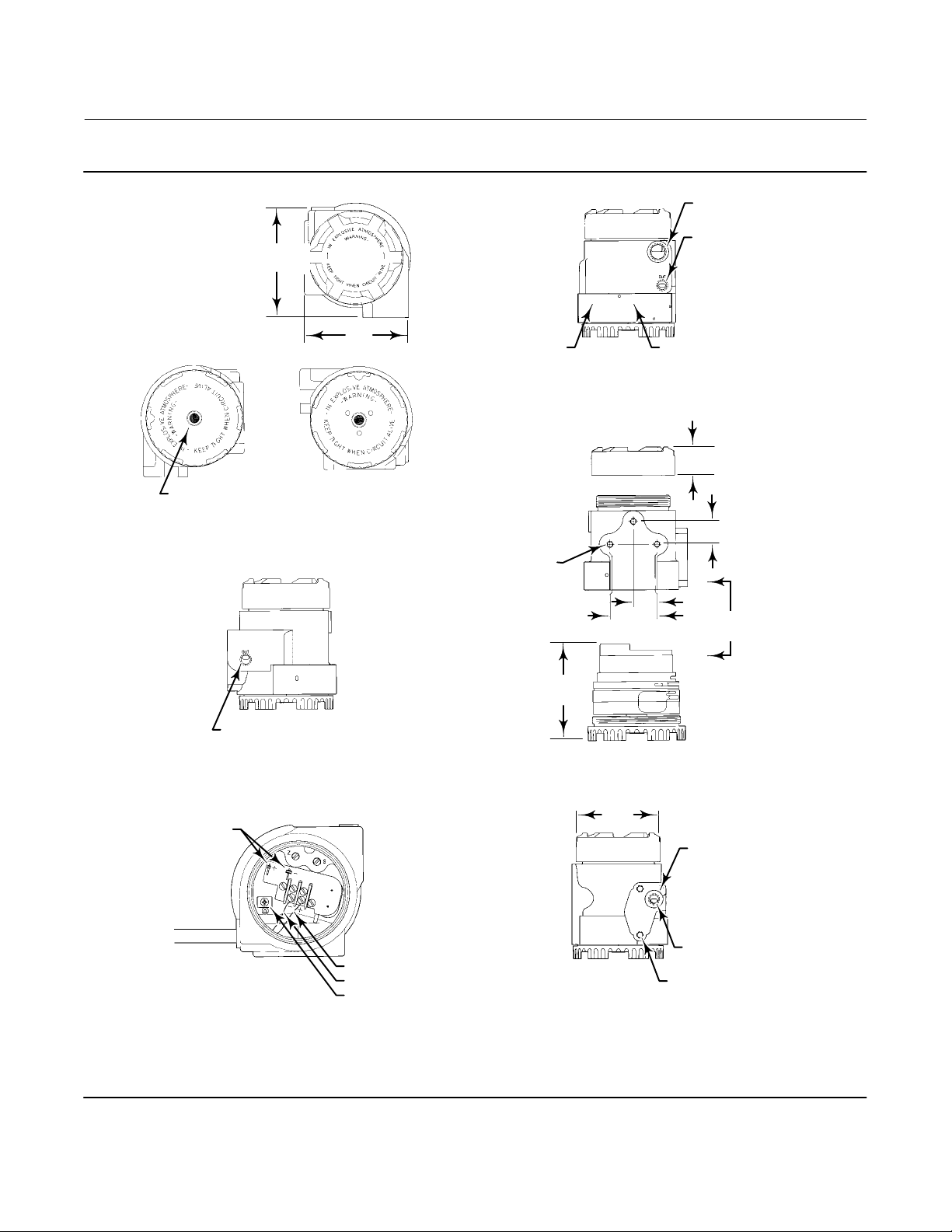
Figure 2-1. Typical Dimensions and Connection Locations (Aluminum Construction Shown)
129
(5.07)
119
STROKE PORT
(4.68)
MODULE COVER WITH
MULTIPLE PORTS
NAMEPLATE
MOUNTING BOLT
HOLES 5/16‐18 (3)
EXHAUST PORT
UNDERNEATH NAMEPLATE
59
(2.31)
CONDUIT CONNECTION
1/2 ‐ 14 NPT
OUTPUT PORT
1/4 ‐ 18 NPT
35
(1.38)
29
(1.13)
29
(1.16)
COVER
REMOVAL
OUTPUT GAUGE PORT 1/4‐18 NPT
TEST PINS
WIRING CONNECTION
NOTE:
REFER TO FIGURE 2-5 FOR TRANSDUCER DIMENSIONS WITH
ATEX / IECEx FLAMEPROOF CERTIFICATIONS
B2473‐1
POSITIVE
NEGATIVE
INTERNAL GROUND
110
(4.33)
102
(4.00)
O‐RING GROOVE
FOR FILTER REGULATOR
SUPPLY PORT 1/4‐18 NPT
5/16‐18 (2)
mm
(INCHES)
12
Page 13
Instruction Manual
D102005X012
846 Transducer
March 2015
Supply Pressure
WARNING
Severe personal injury or property damage may occur from process instability if the instrument supply medium is not
clean, dry air. While use and regular maintenance of a filter that removes particles larger than 40 micrometers in diameter
will suffice in most applications, check with an Emerson Process Management field office and industry instrument air
quality standards if you are unsure about the proper amount or method of air filtration or filter maintenance.
The supply medium must be clean, dry air that meets the requirements of ISA Standard 7.0.01 or ISO 8573-1. An
output span of 0.2 to 1.0 bar (3 to 15 psi) requires a nominal supply pressure of 1.4 bar (20 psi) and a flow capacity not
less than 6.4 normal m
For multirange performance units with higher output spans, the supply pressure should be at least 0.2 bar (3 psi)
greater than the maximum calibrated output pressure.
The air supply line can be connected to the 1/4‐18 NPT supply port, or to the supply port of a filter‐regulator mounted
directly to the transducer. Figures 2-2, 2-3, 2-4, and 2-5 show the installation options.
3
/hr (240 scfh).
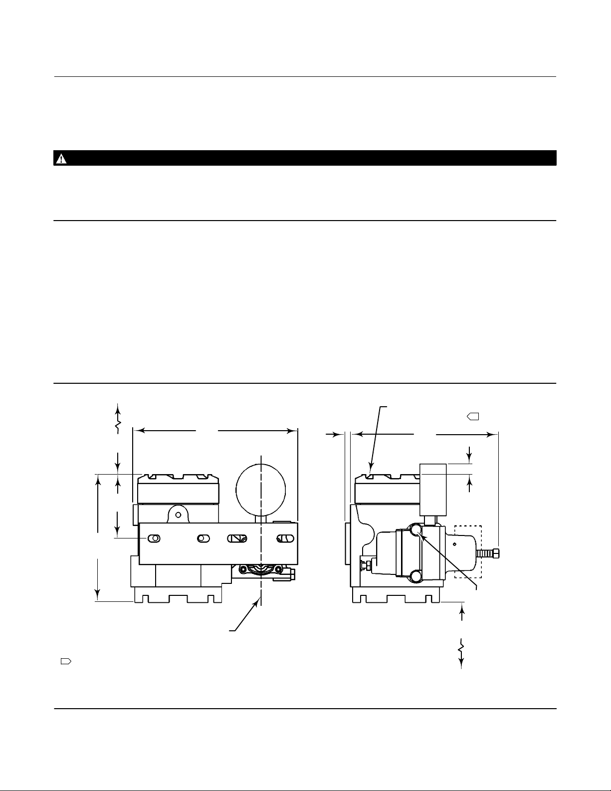
Figure 2-2. Typical Dimensions with Fisher 67CFR Filter/Regulator and Gauges
215
COVER
REMOVAL
CLEARANCE
NOTE:
1 THE MOUNTING POSITIONS SHOWN ALLOW ANY MOISTURE BUILDUP IN THE TERMINAL COMPARTMENT
TO DRAIN TO THE SIGNAL WIRE CONDUIT ENTRANCE. DO NOT MOUNT THE TRANSDUCER WITH THE TERMINAL
COMPARTMENT COVER ON THE BOTTOM; MOISTURE MAY ACCUMULATE IN THE TERMINAL COMPARTMENT
OR PILOT STAGE, PREVENTING PROPER TRANSDUCER OPERATION. THE VERTICAL MOUNT IS MOST EFFECTIVE
FOR MOISTURE DRAINAGE IN WET APPLICATIONS.
14B7361‐D
A6626-3
67
(2.62)
78
(3.08)
156
(6.15)
(8.48)
CENTERLINE
OF ACTUATOR
YOKE MOUNTED
6
(0.25)
FOR PROPER MOISTURE DRAINAGE
THIS END MUST BE UP
191
(7.51)
MODULE
COVER
REMOVAL
CLEARANCE
1
13
(0.50)
FOR ATEX/IECEx
FLAMEPROOF UNITS:
BOLT ENGAGEMENT
NOT TO EXCEED
137
12.9 mm (0.51 INCHES).
(5.38)
5/16‐18 BOLTS
mm
(INCH)
13
Page 14
846 Transducer
March 2015
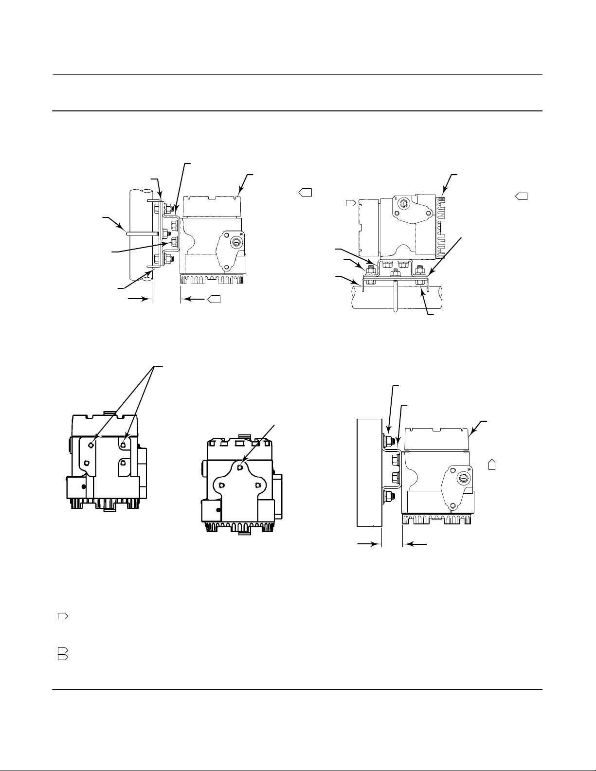
Figure 2-3. Typical Transducer Mounting with Universal Mounting Bracket
Instruction Manual
D102005X012
ADDITIONAL ADAPTER PLATE
PART NUMBER 03311‐0318‐0001
REQUIRED FOR I/P WITH
STAINLESS STEEL HOUSING
U BOLT
5/16‐18 x 5/8
BOLTS
ADAPTER PLATE
(SEE DETAIL “B”)
(1.61)
VERTICAL MOUNT
MOUNTING BRACKET
(SEE DETAIL “A”)
FOR PROPER MOISTURE
DRAINAGE, THIS END
MUST BE UP
5/16‐18 HEX NUT (4 PLACES)
41
3
2‐INCH PIPESTAND MOUNTING
FOR ATEX/IECEx FLAMEPROOF
UNITS: BOLT ENGAGEMENT NOT TO
EXCEED 8.8 mm (0.35 INCHES).
5/16‐18 BOLT HOLES
1
MOUNTING BRACKET
(SEE DETAIL “A”)
ADAPTER PLATE
(SEE DETAIL “B”)
FOR ATEX/IECEx
FLAMEPROOF UNITS:
BOLT ENGAGEMENT
NOT TO EXCEED
8.1 mm (0.32 INCHES).
5/16‐18 BOLT HOLES
2
HORIZONTAL MOUNT
FOR PROPER MOISTURE
DRAINAGE, THE I/P
MUST BE MOUNTED ON
TOP OF THE PIPE
ADDITIONAL ADAPTER
PLATE PART NUMBER
03311‐0318‐0001
REQUIRED FOR I/P
WITH STAINLESS STEEL
HOUSING
5/16‐18 x 3/4 BOLTS (4 PLACES)
5/16‐18 x 3/4 BOLTS
(4 PLACES)
MOUNTING BRACKET (SEE DETAIL “A”)
FOR PROPER
MOISTURE
DRAINAGE,
THIS END
MUST BE UP
1
1
GE06214 SHT 3
BOLT HOLES FOR STAINLESS
STEEL CONSTRUCTION
(COVERLOCK SHOWN)
GE06214 SHT 2
BOLT HOLES FOR ALUMINUM
CONSTRUCTION (COVERLOCK SHOWN)
NOTES:
1 THE MOUNTING POSITIONS SHOWN ALLOW ANY MOISTURE BUILDUP IN THE TERMINAL COMPARTMENT
TO DRAIN TO THE SIGNAL WIRE CONDUIT ENTRANCE. DO NOT MOUNT THE TRANSDUCER WITH THE TERMINAL
COMPARTMENT COVER ON THE BOTTOM; MOISTURE MAY ACCUMULATE IN THE TERMINAL COMPARTMENT
OR PILOT STAGE, PREVENTING PROPER TRANSDUCER OPERATION. THE VERTICAL MOUNT IS MOST EFFECTIVE
FOR MOISTURE DRAINAGE IN WET APPLICATIONS.
2 IF MOUNTED ON HORIZONTAL PIPE, THE I/P MUST BE ON TOP OF THE PIPE FOR PROPER MOISTURE DRAINAGE.
3 THIS DIMENSION IS 44 (1.74) FOR STAINLESS STEEL HOUSING.
14B7332
19B9484‐B
E0786
14
32
(1.25)
WALL/PANEL MOUNTING
(ALUMINUM HOUSING)
mm
(INCH)
Page 15
Instruction Manual
D102005X012
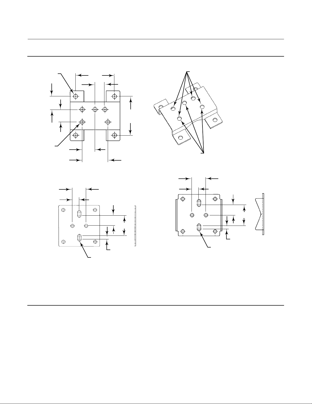
Figure 2-3. Typical Transducer Mounting with Universal Mounting Bracket (continued)
846 Transducer
March 2015
4 X 10 (0.375)
(1.18)
5 X 10 (0.375)
U‐BOLT SLOTS
19 (0.75)
30
29
(1.13)
38
(1.50)
(3.50)
29
(1.16)
(2.312)
59
89
(.89)
23
89
(3.50)
FOR ALUMINUM HOUSING,
ALIGN 3 HOLES WITH I/P HOUSING
DETAIL “A” MOUNTING BRACKET
29
(1.125
57
(2.25)
U‐BOLT SLOTS
19 (0.75)
FOR STAINLESS STEEL HOUSING,
ALIGN 4 HOLES WITH I/P HOUSING
38
(1.50)
29
(1.125
57
(2.25)
2 X 10 (0.375)
03311-0318
4 X 5 (0.188)
2 X 10 (0.375)
DETAIL “B” ADAPTER PLATE
4 X 5 (0.188)
mm
(INCH)
ADDITIONAL ADAPTOR PLATE (PART NUMBER 03311‐0318‐0001)
NOTES:
1. ATTACH THE BRACKET SHOWN IN DETAIL “A” TO THE TRANSDUCER
2. ATTACH THE ADAPTER PLATE SHOWN IN DETAIL “B” TO THE VALVE OR PIPE.
3. CONNECT THE TWO PIECES.
34B4990‐C
34B5000‐B
E0787
REQUIRED FOR I/P WITH STAINLESS STEEL HOUSING
The mounting boss for the air supply connection contains two 5/16‐18 UNC tapped holes that are 2‐1/4 inches apart.
The tapped holes allow direct connection (integral mount) of a 67CFR filter‐regulator, if desired. When the
filter‐regulator is factory mounted, the mounting hardware consists of two 5/16‐18 x 3‐1/2 inch stainless steel bolts
and one O‐ring. When the filter‐regulator is field mounted, the mounting hardware consists of two 5/16‐18 x 3‐1/2
inch stainless steel bolts, two spacers (which may or may not be required) and two O‐rings (of which only one will fit
correctly into the housing O‐ring groove and the other may be discarded). This is due to the fact that the current
housing has been slightly modified from its original design, hence, the additional hardware (if needed) when field
mounting the 67CFR filter‐regulator.
15
Page 16
846 Transducer
March 2015
Figure 2-4. Typical Transducer Dimensions with Gauges
OUTPUT GAGE
FILTER‐
REGULATOR
SUPPLY
GAGE
Instruction Manual
D102005X012
81
(3.2)
14B7332‐D
E0776
49
(1.92)
72
(2.83)
67CFR
14‐18 NPT
SUPPLY CONN
9
(0.36)
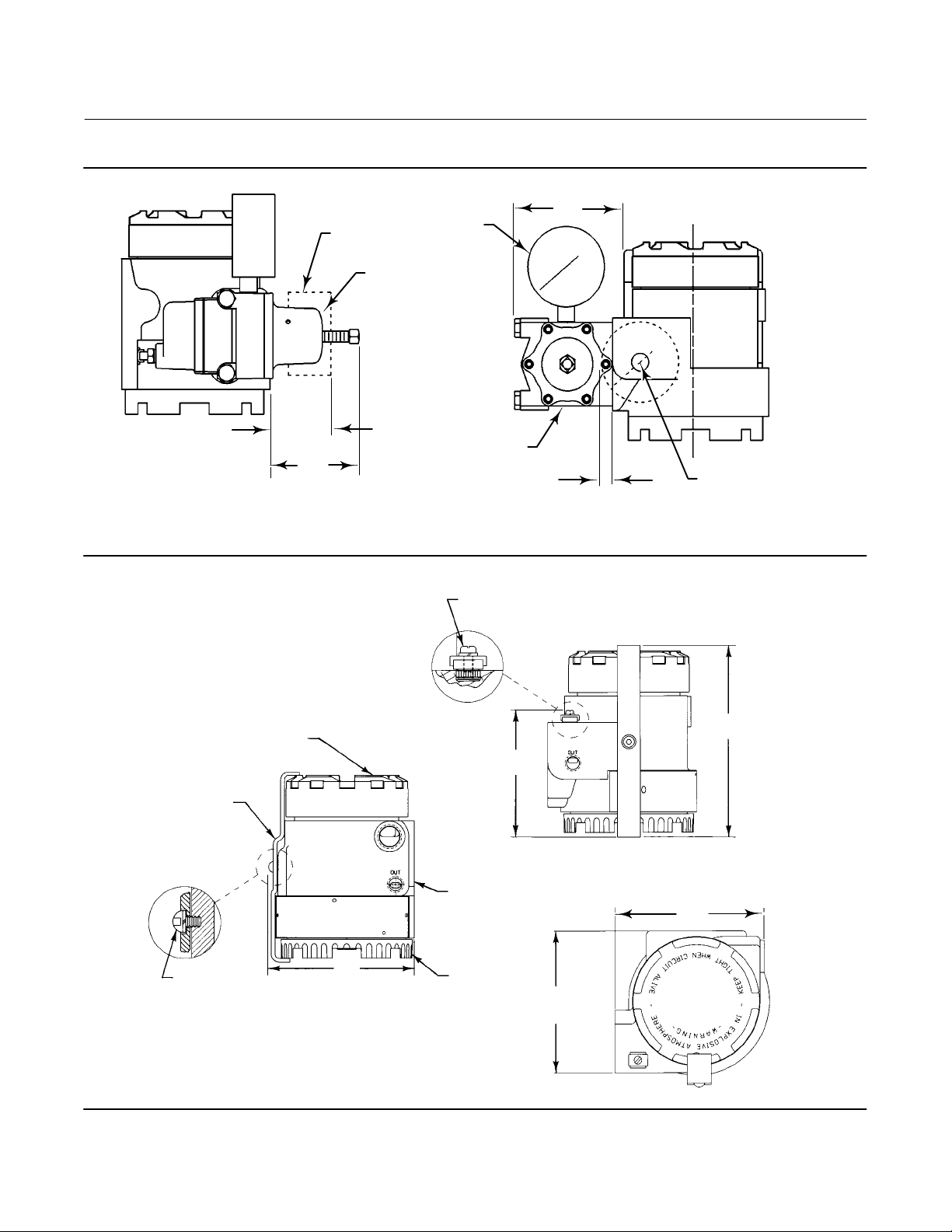
Figure 2-5. Transducer Dimensions with ATEX / IECEx Flameproof Certifications
EXTERNAL EARTHING CONNECTION, SST TERMINAL
CLAMP AND SLOTTED M5 SCREW AND SPLIT RING WASHER
TERMINAL
COMPARTMENT
COVER
3.62
(92)
COVER LOCK
1/4‐18 NPT
OUTLET CONN
PLUGGED WHEN
GAUGE NOT
FURNISHED
162
(6.38)
mm
(INCH)
16
B2465
INTERNAL
HEX DRIVE
ROUND HEAD
SCREW (3 mm)
4.75
(121)
HOUSING
129
(5.07)
MODULE COVER
121
(4.75)
mm
(INCH)
Page 17

Instruction Manual
D102005X012
846 Transducer
March 2015
Output Pressure
Connect the output signal line to the transducer at the output port. The output port is 1/4‐18 NPT, as shown in figure
2-1. The output gauge port can be used as an alternate signal port. If the gauge port is used as a signal port, a threaded
plug must be installed in the output port.
The output gauge port allows connection of an output gauge to provide local output signal indication. The output
gauge port is 1/4‐18 NPT. If an output gauge is not specified, a threaded plug is shipped with the transducer. The plug
must be installed in the output gauge port when the port is not used.
Electrical Connections
WARNING
Personal injury or property damage could result from fire or explosion. In explosive atmospheres, remove power and shut
off the air supply to the I/P unit before attempting to remove the terminal compartment cover or module cover. Failure to
do so could result in an electrical spark or explosion.
Personal injury or property damage could result from an uncontrolled process. Unscrewing the module cover removes
power from the electronics and the output signal will be 0.0 psi. Perform the steps in the WARNING at the beginning of this
section before removing the module cover to ensure the process is properly controlled.
CAUTION
Excessive current can damage the transducer. Do not connect an input current of more than 100 mA to the transducer.
Note
For North American explosion‐proof applications, 846 transducers have been designed so that a conduit seal is not required. For all
other applications install the product per local, regional, or national code, rules, and regulations.
WARNING
Select wiring and/or cable glands that are rated for the environment of use (such as hazardous location, ingress protection,
and temperature). Failure to use properly rated wiring and/or cable glands can result in personal injury or property damage
from fire or explosion.
Signal wiring is brought to the terminal compartment through a 1/2‐14 NPT housing conduit connection, shown in
figure 2-1. Where condensate is common, use a conduit drip leg to help reduce liquid buildup in the terminal
compartment and avoid shorting of the input signal. Electrical connections are made at the terminal block. Internal
and external grounding lugs are provided to facilitate a separate ground when required. The internal ground is shown
in figure 2-1, and the external grounding lug is shown in figure 2-5.
17
Page 18

846 Transducer
March 2015
Connect the positive signal lead to the positive terminal, marked +. Connect the negative signal lead to the negative
terminal, marked -.
Note
Units with the Remote Pressure Reading (RPR) option may cause interference with the analog output signal from some
instrumentation systems. This problem may be solved by placing a 0.2 microfarad capacitor or a HART filter across the output
terminals.
Instruction Manual
D102005X012
Venting Ports
WARNING
This unit will vent to the atmosphere through the stroke port in the module cover and the exhaust port, located under the
nameplate. Do not remote vent this unit.
Stroke Port
The constant bleed of supply medium from the pilot stage is directed out the stroke port, which is a screened hole
located at the center of the module cover. Figure 2-1 shows the location of the stroke port.
Before installing the transducer, ensure the stroke port is clear. Do not mount the transducer in a location where
foreign material may cover the stroke port. For information on using the stroke port, refer to the Troubleshooting
section.
Exhaust Port
The transducer exhausts through a screened port located beneath the instrument nameplate. Figure 2-1 shows the
location of the exhaust port. The nameplate holds the screen in place. Exhaust will occur with a reduction in output
pressure. The transducer should not be mounted in a location where foreign material may clog the exhaust port.
Signal Interruption
Upon loss of input current, or if input current decreases below 3.3 $0.3 mA, the output of the direct action unit will
decrease to less than 0.1 bar (1 psi).
In the same situation, the output of the reverse action unit will increase to near supply pressure.
18
Page 19

Instruction Manual
D102005X012
846 Transducer
March 2015
Section 3 Calibration33
WARNING
The following calibration procedures require taking the transducer out of service. To avoid personal injury and property
damage caused by an uncontrolled process, provide some temporary means of control for the process before taking the
transducer out of service. Also refer to the WARNING at the beginning of the Maintenance section.
Calibration of the 846 requires either an accurate current generator or an accurate voltage generator with a precision
250‐ohm, 1/2‐watt resistor. Figure 3-1 shows how to connect either device.
3
Calibration also requires a precision output indicator and a minimum non-surging air supply of 5.0 normal m
(187 scfh) at 1.4 bar (20 psi) for standard performance units. For multirange performance units, the air supply must be
at least 0.2 bar (3 psi) greater than the maximum calibrated output pressure, up to 2.4 bar (35 psi) maximum.
/hr
For ease of calibration, the output load volume, including the output tubing and output indicator, should be a
minimum of 33 cm
3
(2 cubic inches). Review the information under Signal Interruption in the Installation section
before beginning the calibration procedure.
Before calibration, determine the type of input (full or split range), and the type of output action (direct or reverse).
Consult the factory for split range output calibration. Also, determine if the unit offers standard or multirange
performance. The unit supports eight basic input/output combinations:
Standard Performance
D Full Range Input, Direct Action
D Split Range Input, Direct Action
D Full Range Input, Reverse Action
D Split Range Input, Reverse Action
Multirange Performance
D Full Range Input, Direct Action
D Split Range Input, Direct Action (see note below)
D Full Range Input, Reverse Action
D Split Range Input, Reverse Action (see note below)
Note
Consult your Emerson Process Management sales office
range input or split range output, or both.
or the factory for calibration of multirange performance units with split
19
Page 20

846 Transducer
March 2015
Figure 3-1. Connecting a Current or Voltage Source for Calibration
TO OBTAIN THE 4 AND 20 mA
SET POINTS, ADJUST THE
VOLTAGE SOURCE (V
ADJUST THE CURRENT
SOURCE TO PROVIDE
THE 4 AND 20 mA
SET POINTS
THE VOLTMETER (V
1 AND 5 VOLTS, RESPECTIVELY,
ACROSS THE 250 ohm RESISTOR
) SO
S
) READS
M
Instruction Manual
D102005X012
A6644‐1
CALIBRATION USING A CURRENT SOURCE
CALIBRATION USING A VOLTAGE SOURCE
CAUTION
Excessive current can damage the transducer. Do not connect an input current of more than 100 mA to the transducer.
Table 3-1 lists the various input and output ranges over which the unit may be calibrated.
The input range is selected by changing the position of a jumper located on the electronic circuit board.
Refer to Electronic Circuit Board in the Maintenance section, and figure 6-4 for the location and instruction on
placement.
Table 3-1. Fisher 846 I/P Rangeability Matrix
Output Pressure Range (psi) (Performance Code)
Input
Range
3-15
(S,M)
4-20 n n n n n D n D D n U U n U n U
Common Ranges Misc. Std. Split High Range Splits
.5-30
(M)
3-27
(M)
6-30
(M)
5-25
(M)
0.5-6
(S,M)
.5-18
(S,M)
3-9
(S,M)
9-15
(S,M)
.5-15
(S,M)
15-30
(M)
15-27
(M)
6-18
(S,M)
18-30
(M)
5-15
(S,M)
15-25
(M)
4-12
12-20nn
4-8
8-12
12-16
16-20
S=Standard Performance Unit
M=Multirange Performance Unit
n=Available in Direct or Reverse Action
D=Available in Direct Action Only
J=Available, but if the desired calibration cannot be achieved by adjusting the zero/span screws, unit may require Hi/Lo jumper to be moved. The jumper is located on the circuit board assembly,
and is usually in the Hi position. Disengaging the master module and moving the jumper to the Lo position will allow calibration to the desired range.
U=Special Build Required.
20
n
n
J
J
n n
n
J
n
J
D
J
n
D
n
n
J
J
D
D
J
D
n
n
J
J
n
D
n
n
n
J
U
U
J
n
n
n
n
n
n
U
n
n
n
n
J
J
n
J
J
U
n
Page 21

Instruction Manual
D102005X012
846 Transducer
March 2015
Standard Performance: Full Range Input, Direct Action
WARNING
Refer to the WARNING at the beginning of the Maintenance section.
Use the following procedure to achieve a standard 0.2 to 1.0 bar (3 to 15 psi) output span for a 4 to 20 mA input signal:
1. Remove the module final assembly from the housing. Refer to Removing the Module Final Assembly in the
Maintenance section for an explanation of how to disengage the module final assembly.
2. Confirm that the unit is direct acting. A green electronic circuit board identifies direct‐acting units. Refer to Action
under the heading Electronic Circuit Board in the Maintenance section for more information on direct acting units.
3. Position the range jumper in the Hi position for High Range. Figure 6-4 shows the circuit board jumper positions.
4. Replace the module final assembly in the housing. Refer to Replacing the Module Final Assembly in the
Maintenance section for an explanation of how to engage the module final assembly.
5. Connect the air supply to the air supply port.
6. Connect a precision output indicator to the output signal port.
7. Make sure that the output gauge port has an output gauge or a threaded plug installed. A threaded plug is provided
for units shipped without output gauges.
8. Remove the terminal compartment cover.
9. Connect the current source (or voltage source) positive lead (+) to the terminal block positive (+) and the current
source (250‐ohm resistor lead) negative lead (-) to the terminal block negative (-). Refer to figure 3-1.
CAUTION
Excessive current can damage the transducer. Do not connect an input current of more than 100 mA to the transducer.
10. Apply a 4.0 mA (Vm = 1.0 V) signal, and adjust the zero screw to achieve a 0.2 bar (3.0 psi) output. The output
increases with clockwise rotation of the zero screw.
11. Apply a 20.0 mA (Vm = 5.0 V) signal, and adjust the span screw to achieve a 1.0 bar (15.0 psi) output. The output
increases with clockwise rotation of the span screw.
12. Repeat steps 10 and 11 to verify and complete the calibration.
Multirange Performance: Full Range Input, Direct Action
WARNING
Refer to the WARNING at the beginning of the Maintenance section.
Note
Consult your Emerson Process Management sales office
range input.
or the factory for calibration of multirange performance units with split
21
Page 22

846 Transducer
March 2015
Use the following procedure with a multirange performance unit to achieve the desired direct action output span for a
4 to 20 mA input signal:
1. Perform steps 1 through 9 of the calibration procedure for Standard Performance: Full Range Input, Direct Action.
2. Apply a 4.0 mA (Vm = 1.0 V) signal, and adjust the zero screw to achieve the desired lower limit of the output range.
The lower limit must be between 0.03 and 0.6 bar (0.5 and 9.0 psi). The output increases with clockwise rotation of
the zero screw.
3. Apply a 20.0 mA (Vm = 5.0 V) signal, and adjust the span screw to achieve the desired upper limit of the output
range. The span must be at least 0.4 bar (6.0 psi). The maximum upper limit is 2.0 bar (30.0 psi). The output
increases with clockwise rotation of the span screw.
4. Repeat steps 2 and 3 to verify and complete the calibration.
Instruction Manual
D102005X012
Standard Performance: Split Range Input, Direct Action
WARNING
Refer to the WARNING at the beginning of the Maintenance section.
4 to 12 mA Input Signal
Use the following calibration procedure to produce a 0.2 to 1.0 bar (3 to 15 psi) output span for a 4 to 12 mA input
signal:
1. Perform steps 1 through 9 of the calibration procedure for Standard Performance: Full Range Input, Direct Action.
2. Apply an input of 4.0 mA (Vm = 1.0 V), and adjust the zero screw to achieve an output of 0.2 bar (3.0 psi).
3. Apply an input of 12.0 mA (Vm = 3.0 V), and adjust the span screw to achieve an output of 1.0 bar (15.0 psi).
4. Repeat steps 2 and 3 to verify and complete the calibration.
12 to 20 mA Input Signal
Use the following calibration procedure to produce a 0.2 to 1.0 bar (3 to 15 psi) output span for a 12 to 20 mA input
signal:
Note
There may be some span interaction with zero in this range, and the following steps compensate for this.
1. Perform steps 1 through 9 of the calibration procedure for Standard Performance: Full Range Input, Direct Action.
2. Apply an input of 4.0 mA (Vm = 1.0 V), and adjust the zero screw to achieve an output of 0.2 bar (3.0 psi).
3. Apply an input of 12.0 mA (Vm = 3.0 V), and adjust the span screw to achieve an output of 1.0 bar (15.0 psi).
4. Maintain the input of 12.0 mA (Vm = 3.0 V), and adjust the zero screw to achieve an output of 0.2 bar (3.0 psi). The
unit may not turn down this low; if it does not, go to step 7.
5. If the output reaches 0.2 bar (3.0 psi) in step 4, apply an input of 20.0 ma (Vm = 5.0 V) and note the error (the actual
reading versus 15.0 psi). Adjust the span screw to overcorrect the error by a factor of two. For example, if the
reading was 0.9 bar (14.95 psi), adjust the span screw to achieve an output of 1.1 bar (15.05 psi).
22
Page 23

Instruction Manual
D102005X012
6. Repeat steps 4 and 5 to verify and complete the calibration.
7. Turn off the air supply. Remove the module final assembly from the housing. Place the range jumper in the Lo
position for Low Range, as indicated in figure 6-4. Replace the module final assembly. Turn on the air supply.
8. Apply an input of 12.0 mA (Vm = 3.0 V), and adjust the zero screw to achieve an output of 0.2 bar (3.0 psi).
9. Apply an input of 20.0 mA (Vm = 5.0 V), and note the error (the actual reading versus 15.0 psi). Adjust the span
screw to overcorrect the error by a factor of two. For example, if the reading was 0.9 bar (14.95 psi), adjust the span
screw to achieve an output of 1.1 bar (15.05 psi).
10. Repeat steps 8 and 9 to verify and complete the calibration.
846 Transducer
March 2015
Standard Performance: Full Range Input, Reverse Action
WARNING
Refer to the WARNING at the beginning of the Maintenance section.
Use the following procedure on reverse action units to achieve a 1.0 to 0.2 bar (15 to 3 psi) output span for a 4 to 20
mA input signal:
1. Perform steps 1 through 9 under Standard Performance: Full Range Input, Direct Action, except for step 2. In place
of step 2, confirm that the unit is reverse acting. A red electronic circuit board identifies reverse‐acting units. Refer
to Action
acting units.
2. Apply an input of 4.0 mA (Vm = 1.0 V), and adjust the zero screw to achieve an output of 1.0 bar (15.0 psi).
3. Apply an input of 20.0 mA (Vm = 5.0 V), and adjust the span screw to achieve an output of 0.2 bar (3.0 psi).
4. Repeat steps 2 and 3 to verify and complete the calibration.
under the heading Electronic Circuit Board in the Maintenance section for more information on reverse
Multirange Performance: Full Range Input, Reverse Action
WARNING
Refer to the WARNING at the beginning of the Maintenance section.
Note
Consult your Emerson Process Management sales office
range input.
Use the following procedure with a multirange unit to achieve the desired reverse action output span for a 4 to 20 mA
input signal:
or the factory for calibration of multirange performance units with split
1. Perform steps 1 through 9 of the calibration procedure for Standard Performance: Full Range Input, Direct Action,
except for step 2. In place of step 2, confirm that the unit is reverse acting. A red electronic circuit board identifies
reverse‐acting units. Refer to Action under the heading Electronic Circuit Board in the Maintenance section for more
information on reverse acting units.
2. Apply an input of 4.0 mA (Vm = 1.0 V), and adjust the zero screw to achieve the desired upper limit of the output
range. The 4 mA point must be between 0.6 and 2.0 bar (9.0 and 30.0 psi). The output increases with clockwise
rotation of the zero screw.
23
Page 24

846 Transducer
March 2015
3. Apply an input of 20.0 mA (Vm = 5.0 V), and adjust the span screw to achieve the desired lower limit of the output
range. The span must be at least 0.7 bar (11.0 psi). The lower limit of the 20.0 mA setting is 0.03 bar (0.5 psi). The
output increases with clockwise rotation of the span screw.
4. Repeat steps 2 and 3 to verify and complete the calibration.
Instruction Manual
D102005X012
Standard Performance: Split Range Input, Reverse Action
WARNING
Refer to the WARNING at the beginning of the Maintenance section.
4 to 12 mA Input Signal
Use the following procedure on reverse action units to achieve a 1.0 to 0.2 bar (15 to 3 psi) output signal for a 4 to 12
mA input signal:
1. Perform steps 1 through 9 of the calibration procedure for Standard Performance: Full Range Input, Direct Action,
except for step 2. In place of step 2, confirm that the unit is reverse acting. A red electronic circuit board identifies
reverse‐acting units. Refer to Action under the heading Electronic Circuit Board in the Maintenance section for more
information on reverse acting units.
2. Apply an input of 4.0 mA (Vm = 1.0 V), and adjust the zero screw to achieve an output of 1.0 bar (15.0 psi).
3. Apply an input of 12.0 mA (Vm = 3.0 V), and adjust the span screw to achieve an output of 0.2 bar (3.0 psi).
4. Repeat steps 2 and 3 to verify and complete the calibration.
12 to 20 mA Input Signal
Use the following procedure on reverse action units to achieve a 1.0 to 0.2 bar (15 to 3 psi) output signal for a 12 to 20
mA input signal:
Note
There may be some span interaction with zero in this range, and the following steps compensate for this.
1. Perform steps 1 through 9 of the calibration procedure for Standard Performance: Full Range Input, Direct Action,
except for step 2. In place of step 2, confirm that the unit is reverse action. A red electronic circuit board identifies
reverse‐acting units. Refer to Action under the heading Electronic Circuit Board in the Maintenance section for more
information on reverse acting units.
2. Apply an input of 4.0 mA (Vm = 1.0 V), and adjust the zero screw to achieve an output of 1.0 bar (15.0 psi).
3. Apply an input of 12.0 mA (Vm = 3.0 V), and adjust the span screw to achieve an output of 0.2 bar (3.0 psi).
4. Maintain the input of 12.0 mA (Vm = 3.0 V), and adjust the zero screw to achieve an output of 1.0 bar (15.0 psi). The
unit may not turn up this high; if it does not, go to step 7.
5. If the output reaches 15.0 psi in step 4, apply an input of 20 mA, and adjust the span screw to achieve a 3.0 psi
output. Apply an input of 20 mA (Vm = 5.0 V), and note the error (the actual reading versus 3.0 psi). Adjust the span
screw to overcorrect the error by a factor of two. For example, if the reading was 2.95 psi, adjust the span screw to
achieve an output of 3.05 psi.
24
Page 25

Instruction Manual
D102005X012
6. Repeat steps 4 and 5 to verify and complete the calibration.
7. If the 12.0 mA (Vm = 3.0 V) cannot be adjusted to 1.0 bar (15.0 psi) in step 4, turn off the air supply. Remove the
module final assembly from the housing. Place the range jumper in the Lo position for Low Range, as shown in
figure 6-4. Replace the module final assembly. Turn on the air supply.
8. Apply an input of 12.0 mA (Vm = 3.0 V), and adjust the zero screw to achieve an output of 1.0 bar (15.0 psi).
9. Apply an input of 20 mA (Vm = 5.0 V), and note the error (the actual reading versus 3.0 psi). Adjust the span screw
to overcorrect the error by a factor of two. For example, if the reading was 2.95 psi, adjust the span screw to achieve
and output of 3.05 psi.
10. Repeat steps 8 and 9 to verify and complete the calibration.
846 Transducer
March 2015
Transporting the Module Final Assembly
The transducer allows the module final assembly to be removed while the housing is in its installed position. In the
event the transducer does not function properly, an operational module final assembly can be taken to the field and
exchanged with the nonfunctional module.
After the transducer is calibrated in the shop, the module final assembly can be removed from the housing. At the time
the span and zero screws disengage, there will be minimal effect on the calibrated span. The calibrated module can
now be taken to the field. Ensure that the span and zero potentiometers are not moved from their calibrated positions.
25
Page 26

846 Transducer
March 2015
Instruction Manual
Section 4 Principle of Operation44
The following paragraphs describe the functional parts of the 846. Figure 4-1 shows the block diagram.
Figure 4-1. Functional Parts Block Diagram
4 to 20 MA
INPUT
ELECTRONIC CIRCUIT
MAGNETIC ACTUATOR
SOLID‐STATE
PILOT STAGE
PRESSURE
SENSOR
D102005X012
BOOSTER STAGE
TO VALVE ACTUATOR
A6324‐1
3 TO 15 PSI
OUTPUT, TYPICAL
Electronic Circuit
During operation, the input current signal is received by the transducer's electronic circuit and compared to the output
pressure from the booster stage. A solid‐state pressure sensor is part of the electronic circuit and monitors the booster
stage output. The silicon‐based sensor uses strain gauge thin film technology.
The sensors pressure signal is fed to a simple internal control circuit. By using this technique, the transducer's
performance is set by the sensor/circuit combination. Changes in output load (leaks), variations in supply pressure, or
even component wear are sensed and corrected by the sensor/circuit combination. Electronic feedback allows crisp
dynamic performance and readily compensates for output changes induced by vibration.
Note
Because the transducer is electronic in nature, it is not well‐modeled in the loop as a simple resistor in series with an inductor. It is
better thought of as a 50‐ohm resistor in series with a 6.0 V voltage drop, with negligible inductance.
This is important when calculating the loop load. When the transducer is used in series with a microprocessor‐based
transmitter, the noninductive nature of the transducer allows digital signals to successfully pass through undistorted.
26
Page 27

Instruction Manual
D102005X012
846 Transducer
March 2015
Magnetic Actuator
The electronic circuit controls the level of current flowing through the actuator coil, which is located in the
pilot/actuator assembly. A change to the level of coil current is made by the electronic circuit when it senses a
discrepancy between the pressure measured by the sensor and the pressure required by the input signal.
The actuator performs the task of converting electrical energy (current) to motion. It uses a coaxial moving magnet
design optimized for efficient operation and is highly damped at its mechanical resonance. A silicone rubber
diaphragm helps to protects its working magnetic gaps from contamination.
Pilot Stage
The pilot stage contains two opposed fixed nozzles: the supply nozzle and the receiver nozzle. It also contains the
deflector, which is the moving element. See figures 4-2 and 4-3. The supply nozzle is connected to the supply air and
provides a high‐velocity air stream. The receiver nozzle captures the air stream and converts it back to pressure. The
receiver nozzle pressure is the output pressure of the pilot stage.
Figure 4-2. Deflector/Nozzle Pilot Stage Operation (Direct Action)
REGULATED
AIR SUPPLY
REGULATED
AIR SUPPLY
A6645
HIGH OUTPUT PRESSURE
PRESSURE TO
BOOSTER STAGE
LOW OUTPUT PRESSURE
DEFLECTED NOZZLE
FLOW PATTERN
PRESSURE TO
BOOSTER STAGE
To vary the pilot output pressure, the high‐velocity stream is diverted away from the receiver nozzle by the deflector,
which is a cylindrical, aerodynamic body located between the two nozzles.
In response to a change in actuator coil current, the deflector is repositioned between the nozzles. There is a linear
relationship between the coil current and the pilot stage output pressure. For direct action units, the power‐off, or
fail‐safe, position of the top of the deflector is near the center of the stream and results in nearly zero pilot output
pressure. As the coil is energized, the deflector is drawn out of the stream.
For reverse action units, the power‐off, or fail‐safe, position of the deflector is completely out of the stream. The result
is maximum pilot output pressure. As the coil is energized, the deflector moves into the stream, resulting in a
decreased pilot output pressure.
The deflector material is tungsten carbide, and the nozzles are 316 stainless steel. The nozzles have a large bore of
0.41 mm (0.016 inches), which provides good resistance to plugging.
27
Page 28

846 Transducer
March 2015
Figure 4-3. Detail of Deflector/Nozzle Pilot Stage
W6287
Instruction Manual
D102005X012
Booster Stage
The receiver nozzle pressure controls the booster stage, which has a poppet valve design. An increase in receiver
nozzle pressure positions the valving in the booster stage to produce an increase in the transducer output signal. A
decrease in the receiver nozzle pressure positions the valving in the booster stage to allow exhaust to occur,
decreasing the output signal.
The booster stage operates using a 3:1 pressure gain from the pilot stage. High flow rate capability is achieved by large
flow area poppet design and internal porting having low flow resistance. The booster stage design provides very good
stability in high vibration applications, and the poppet valve technology provides resistance to plugging.
28
Page 29

Instruction Manual
D102005X012
846 Transducer
March 2015
Section 5 Troubleshooting55
The modular design and unitized subassemblies of the 846 allows for quick and easy troubleshooting and repair. This
section presents information on the diagnostic features and procedures for troubleshooting both models in service or
in the shop.
Diagnostic Features
If a control loop does not perform properly and the cause of malfunction has not been determined, two features of the
transducer can be used to determine if the transducer is at fault: the stroke port and Remote Pressure Reading.
Stroke Port
The stroke port provides a way to quickly increase the transducer output, giving a rough measure of the unit's
functionality. A hole in the module cover vents the constant bleed from the pilot stage. When the hole is covered,
pressure at the pilot stage receiver nozzle increases, which in turn increases the output. Output pressure will increase
to within 2 psi of supply pressure for either direct or reverse action. If output pressure does not increase to this level, it
may indicate that supply air is not reaching the pilot stage or that a pilot stage nozzle is plugged.
Note
If the stroke port diagnostic feature is not desired, the transducer is available with an optional cover that contains multiple stroke
ports, as shown in figure 2-1. This prevents increasing the output by covering the stroke port.
Remote Pressure Reading (RPR)
Remote Pressure Reading (RPR) is an optional diagnostic feature that enables the user to determine the output
pressure from any location along the signal wire path. For loop troubleshooting, this allows the user to confirm the
functionality of the transducer from a remote location.
A frequency signal directly proportional to the output pressure is superimposed on the input signal loop. The
frequency range of the RPR function is 0 to 10,000 Hz.
A jumper on the circuit board activates the Remote Pressure Reading function. The Maintenance section provides
instruction on positioning the jumper. The jumper, shown in figure 6-4, has two positions: N for ON, or D for OFF. The
RPR jumper is in the N (ON) position when the unit ships from the factory, unless otherwise specified.
Using a Frequency Counter to Read the RPR Signal
A frequency counter can be used for Remote Pressure Reading. The frequency counter displays the RPR output
frequency that can be converted to output pressure using a simple mathematical line formula as shown below. Figure
5-1 shows the wiring connections.
Notes
The Remote Pressure Reading (RPR) frequency signal has an amplitude of 0.4 to 1.0 V peak‐to‐peak. If other noise (frequency) with
a comparable or greater amplitude is present on the line, it may make the RPR frequency signal unreadable.
The following procedure is applicable for 846 transducers manufactured starting March 2015. Contact your Emerson Process
Management sales office for information on reading the RPR signal for products purchased prior to this date.
29
Page 30

846 Transducer
March 2015
Equations
(1) P = m(p) + b
P = pressure
p = frequency
P
(2) m =
2
p
2
Procedure
- P
- p
Instruction Manual
D102005X012
Example
P
1)
1
1
2)
= 3 psig
1
= 15 psig p2 = 9000 Hz
P
2
m = =
15 - 3 12
9000-6000 3000
= 6000 Hz
p
1
1) Find frequencies at zero and span pressure.
2) Solve for m, using equation (2).
3) Solve for b by inserting m, initial pressure,
and initial frequency into equation (1).
4) Insert m and b into equation (1) to find conversion formula.
Figure 5-1. Wiring Connections for Frequency Counter
CONTROLLER
POWER
SUPPLY
FREQUENCY
COUNTER
3)
12
3 = (6000) + b
3000
b = 3-24
b = -21
4)
12
P = (p) - 21
3000
TEST
PINS
POSITIVE
NEGATIVE
GROUND
B2466
In‐service Troubleshooting
A number of simple checks can be made on the transducer while the unit is in service. Figure 5-2 shows a
troubleshooting flowchart.
1. Make sure that the module cover is tight. The cover should be hand‐tightened and then advanced 1/4 to 1/2 turn
(24 to 27 NSm) (18 to 20 lbfSft).
2. Confirm the general functionality of the unit by using the diagnostic features described earlier in this section.
30
Page 31

Instruction Manual
D102005X012
Figure 5-2. Field Troubleshooting Flowchart
846 Transducer
March 2015
TROUBLESHOOTING
FROM THE CONTROL ROOM
TROUBLESHOOTING
IN THE FIELD
NOTE:
AFTER FINAL CORRECTIVE ACTION, CHECK LOOP OPERATION.
IF NOT OK, RESTART TROUBLESHOOTING PROCEDURE.
1 REFER TO REPLACING THE MODULE FINAL ASSEMBLY
IN SECTION 6.
C0789
3. Confirm that the filter‐regulator is not full of water or oil and that supply air is reaching the unit. The air supply
pressure should be at least 0.2 bar (3 psi) greater than the maximum calibrated output pressure.
4. Confirm that there are no major leaks in the output signal line or from the output gauge port.
5. Confirm that there are no obstructions and the screens are clean in the stroke port or the exhaust port.
31
Page 32

846 Transducer
March 2015
Instruction Manual
D102005X012
WARNING
Personal injury or property damage could result from an uncontrolled process. Unscrewing the module cover removes
power from the electronics and the output signal will be 0.0 psi. Before removing the module cover, ensure the process is
properly controlled.
WARNING
Personal injury or property damage could result from fire or an explosion. In explosive atmospheres, remove power and
shut off the air supply to the transducer before attempting to remove the terminal compartment cover or module cover.
Failure to do so could result in an electrical spark or explosion.
6. If applicable, remove the cover lock and screw to allow access to the terminal compartment cover.
7. Remove the terminal compartment cover (see Warning above), and use a milliammeter, or a digital voltmeter to
confirm that proper input current is supplied to the transducer.
8. Remove the terminal compartment cover (see Warning above), and short the loop across the positive (+) and the
negative (-) terminals to check the output. The output should be nearly 0 psi. If the output is not 0 psi, replace the
module final assembly.
9. Remove the terminal compartment cover (see Warning above), and, using a digital voltmeter, check the voltage
between the transducer positive (+) and negative (-) terminals. The voltage should measure 6.0 to 8.2 V. A lower
voltage can indicate a short in the input wires or defective controller. No voltage can indicate an open circuit in the
control loop. A voltage of greater than 8.5 volts indicates a problem with the transducer, a faulty or corroded
connection at the transducer, or an overcurrent condition. Replace the module final assembly. If the voltage is still
not in the proper range (6.0 to 8.2 V), remove the terminal block and terminal block connection board. Apply power
to the electrical feedthroughs. (Note the polarity of the feedthroughs, shown in figure 6-8.) Recheck the voltage. If
the voltage is in the proper range, replace the terminal block and terminal block connection board. If the voltage is
still not in the proper range, replace the housing.
10. Prepare to remove the module final assembly from the housing, or to remove the transducer from its mounting
bracket. Refer to Module Final Assembly in the Maintenance section for instructions on removing the module final
assembly from the module housing.
WARNING
Personal injury or property damage could result from an uncontrolled process. Unscrewing the module cover removes
power from the electronics and the output signal will be 0.0 psi. Before removing the module cover, ensure the process is
properly controlled.
With the module final assembly removed from the housing, the following checks can be made.
1. Review the position of the Remote Pressure Reading jumper (if so equipped) and range jumper to confirm that they
are placed in the desired position. Refer to Electronic Circuit Board in the Maintenance section, and figure 6-4 for
the location of these jumpers and instructions on placement.
2. Observe the position and condition of the three module O‐rings to confirm they make a tight seal.
3. Verify that the O‐ring is correctly positioned in the groove on the flat face of the module cover. Refer to figure 6-8
for an exploded view.
4. Inspect the porting on the module final assembly to determine if large amounts of contaminants have entered the
transducer.
32
Page 33

Instruction Manual
D102005X012
Before making the following checks, disconnect both signal wires from the transducer, and ensure the module final
assembly is removed from the housing.
1. Using an ohmmeter, check the electrical connections in the housing terminal compartment. The circuit should
show an open between the positive (+) and negative (-) terminals. If not, replace the housing or terminal block and
connection board.
2. Use a wire jumper to connect the two electrical feedthroughs located in the module compartment. The resistance
between the positive (+) and negative (-) terminals in the terminal compartment should be 10 ohms. If not, check
the electrical feedthroughs for short or open circuits. If a short or open circuit is found, replace the housing.
3. With the electrical feedthroughs jumpered as stated above, connect the ohmmeter to either the positive (+) or
negative (-) terminal and the grounding lug. The circuit should show an open. If not, check for a short to the
housing.
4. Remove the module from the module cover and inspect the pilot/actuator assembly for damage or clogging.
Some of the previous troubleshooting steps may be inconvenient to perform in the field. It may be best to make use of
the modular design of the 846 and keep a spare, calibrated module final assembly available for exchange. If the
module final assembly is to be transported to the shop for repair, first remove it from the module cover. Attach the
spare module final assembly to the module cover. Refer to Module Final Assembly in the Maintenance section for
complete instructions. The nonfunctioning module can then be returned to the shop for troubleshooting.
846 Transducer
March 2015
Troubleshooting in the Shop
If the entire transducer is brought to the shop for troubleshooting, then the preceding sequence applies. If only the
module final assembly has been brought to the shop, then use another 846 housing as a test fixture. Insert the module
into the test fixture. Perform the previous steps (as they apply) of the In‐service Troubleshooting procedure.
To further aid troubleshooting, the module final assembly can be broken down into three subassemblies. The
troubleshooting sequence consists of exchanging the subassemblies with known working ones to determine which is
at fault. The three subassemblies are the pilot/actuator assembly, the electronic circuit board, and the module
subassembly. The module subassembly consists of the module final assembly with both the pilot/actuator assembly
and electronic circuit board removed.
1. Remove the pilot/actuator assembly. Refer to Pilot/Actuator Assembly in the Maintenance section for complete
removal information.
CAUTION
Do not apply force to the deflector bar while cleaning the nozzles. Doing so could alter the alignment or disable the
deflector bar mechanism.
CAUTION
Do not use chlorinated solvents for cleaning the pilot/actuator assembly. The chlorinated solvents will deteriorate the
rubber diaphragm.
a. Inspect the nozzles and deflector. If they show a buildup of contaminants, clean the nozzles by gently inserting a
wire with a maximum diameter of 0.38 mm (0.015 inches). Clean the deflector, if necessary, by spraying with
contact cleaner.
33
Page 34

846 Transducer
March 2015
Instruction Manual
D102005X012
b. Make sure the O‐rings are lightly lubricated with silicone grease and properly seated.
c. Reassemble and check operation.
d. If after cleaning the transducer does not function, replace the pilot/actuator assembly with a new one.
e. Reassemble and check operation.
2. Remove the electronic circuit board from the module final assembly. The Maintenance section describes how to
remove the board.
a. Inspect the O‐rings around the sensor for damage and replace them if necessary.
b. Check the sensor port and areas around the sensor for foreign material, and clean if necessary.
c. Reassemble and check operation.
d. If the transducer does not function, replace the electronic circuit board with a new one. Refer to Electronic
Circuit Board in the Maintenance section for complete removal information.
e. Reassemble and check operation.
3. The module subassembly is aligned at the factory and should not be further disassembled. If the above steps fail to
produce a working unit, the module subassembly is faulty and should be replaced.
34
Page 35

Instruction Manual
D102005X012
846 Transducer
March 2015
Section 6 Maintenance66
This section describes the major components, assembly, and disassembly of 846 current‐to‐pressure transducers.
WARNING
To avoid personal injury or property damage from the sudden release of pressure or air:
D Always wear protective clothing, gloves, and eyewear when performing any maintenance operations.
D Disconnect any operating lines providing air pressure, electric power, or a control signal to the actuator. Be sure the
actuator cannot suddenly open or close the valve.
D Use bypass valves or completely shut off the process to isolate the valve from process pressure. Relieve process pressure
on both sides of the valve.
D Use lock‐out procedures to be sure that the above measures stay in effect while you work on the equipment.
D Check with your process or safety engineer for any additional measures that must be taken to protect against process
media.
WARNING
The presence of Emerson Process Management personnel and approval agency personnel may be required if you service
(other than normal, routine maintenance, such as calibration) or replace components on an 846 transducer that carries a
third‐party approval. When replacing components, use only components specified by the factory. Substitution with other
components may void the third‐party approval and result in personal injury or property damage.
Use only the procedures, and component replacement techniques specifically referenced in this manual. Unauthorized
procedures and improper techniques can cause poor quality repairs, impair the safety features of the device, and affect
product performance and the output signal used to control a process.
Module Final Assembly
WARNING
Refer to the Maintenance WARNINGS at the beginning of this section.
The active mechanical and electrical components of the transducer are incorporated into a single, field‐replaceable
module called the module final assembly, as shown in figure 6-1. Electrical connection between the terminal
compartment and module final assembly is made by electrical feedthroughs that extend into the module
compartment. The feedthroughs enter sockets on the electronic circuit board. The span and zero screws extend
through the terminal compartment wall into the module compartment. Connection to the span and zero
potentiometers on the electronic circuit board is made by hook and loop fasteners.
35
Page 36

846 Transducer
March 2015
Instruction Manual
D102005X012
The module final assembly has three separate radial ports. The upper port is for supply air, the middle port for the
output signal, and the lower ports for exhaust. Three O‐rings separate the ports. The two lower O‐rings are the same
size, and the upper O‐ring is slightly smaller. Table 6-1 shows O‐ring sizes.
The module final assembly is attached to the module cover, which allows insertion and removal, and can be separated
from the module cover for further disassembly. A module cover O‐ring provides a seal between the module cover and
module final assembly. Table 6-1 shows the O‐ring sizes. A slip ring is located around the module feet. It allows the
module cover to turn easily when the module final assembly is being removed from the housing.
The module final assembly consists of three major subassemblies, as shown in figure 6-1. They are the electronic
circuit board, pilot/actuator assembly, and module subassembly.
Table 6-1. O‐Ring Sizes
Description Qty. Size
Module O‐rings 1
2
Pilot/Actuator O‐rings 2 006
Circuit Board O‐rings 2
1
Module Cover O‐ring 1 238
Terminal Cover O‐ring 1 238
Filter‐Regulator O‐ring 1 114
043
042
016
005
36
Page 37

Instruction Manual
D102005X012
846 Transducer
March 2015
Figure 6-1. Fisher 846 Exploded View
ELECTRONIC
CIRCUIT BOARD O‐RINGS
TERMINAL COVER
MODULE
1
O‐RINGS
MODULE HOUSING
V‐GROOVE
ALIGNMENT
MARK
ELECTRONIC CIRCUIT BOARD SCREWS
ELECTRONIC CIRCUIT BOARD
MODULE SUBASSEMBLY
PILOT/ACTUATOR
ASSEMBLY
PILOT/ACTUATOR
ASSEMBLY O‐RINGS
PILOT/ACTUATOR
ASSEMBLY SCREWS
MODULE FINAL ASSEMBLY
V‐GROOVE
MODULE FEET
C0790
KEY SLOT
STROKE PORT
SCREEN
RETAINING CLIP (2)
O‐RING CLIP
COVER SLOT (2)
SLIP RING
O‐RING
ALIGNMENT KEY
MODULE COVER
NOTE:
1 THREE O‐RINGS ARE REQUIRED FOR THE MODULE SUBASSEMBLY.
FOR ATEX / IECEx—FLAMEPROOF APPROVED UNITS THE TWO UPPER O‐RINGS ARE SILICONE AND THE
LOWER O‐RING IS NITRILE. ALL OTHER UNITS HAVE THREE NITRILE O‐RINGS.
MODULE COVER
INDICATING BOSS
37
Page 38

846 Transducer
March 2015
Instruction Manual
D102005X012
Removing the Module Final Assembly
The module final assembly is attached to the module cover. Removing the module cover automatically removes the
module final assembly from the housing. When the module cover is unscrewed, the electrical feedthroughs and span
and zero adjustments automatically disengage. The internal air ports are also disengaged. The air supply to the
transducer should be turned off to prevent uncontrolled air loss through the housing.
WARNING
Personal injury or property damage could result from an uncontrolled process. Unscrewing the module cover removes
power from the electronics and the output signal will be 0.0 psi.
Refer to the WARNING at the beginning of this section before removing the module cover to ensure the process is properly
controlled.
WARNING
Personal injury or property damage could result from fire or an explosion. In explosive atmospheres, remove power and
shut off the air supply to the transducer before attempting to remove the terminal compartment cover or module cover.
Failure to do so could result in an electrical spark or explosion.
Use the following steps to remove the module final assembly from the housing and module cover:
1. Shut off the air supply. If applicable, remove the cover lock and screw to allow access to the terminal compartment
cover. Unscrew the module cover. When the module cover threads clear the housing, slowly pull on the cover, and
the module final assembly will gradually come out of the housing.
Note
The module and the housing are designed for minimal clearance; therefore, patience may be required while pulling on the cover.
Time must be allowed for release of the vacuum effect between the housing and module. If the module becomes tilted and cannot
be removed, reinsert it completely into the housing and fully engage the module cover threads. Then proceed again with removal,
ensuring that you pull slowly in a straight line.
Support both the module cover and the module final assembly as it comes out of the housing. This is to prevent
dropping them, should they become detached accidentally.
WARNING
Do not grip the module cover threads. The threads are sharp and may cause minor injury. Wear gloves when removing the
module cover.
2. Prepare to remove the module final assembly from the module cover. Align the module feet with the two interior
cover slots. To accomplish this, identify the indicating boss on the module cover, shown in figure 6-2.
Grasp the module cover with one hand and the module final assembly with the other hand. Rotate the module final
assembly so that the module alignment key is directly above the indicating boss on the module cover. Figure 6-2
shows the module alignment key and the indicating boss. The module feet are now aligned with the cover slots.
38
Page 39

Instruction Manual
D102005X012
846 Transducer
March 2015
3. Remove the module final assembly from the module cover. To accomplish this, hold the cover steady, and push the
module final assembly in the direction of the module cover indicating boss. At the same time, lift the opposite foot
of the module final assembly out of the cover slot, as shown in figure 6-3.
Figure 6-2. Alignment Key Above Module Cover
Indicating Boss
MODULE
ALIGNMENT
KEY
INDICATING
BOSS
A6649
Figure 6-3. Removing the Module Final Assembly
from the Module Cover
A6650
Replacing the Module Final Assembly
Use the following procedure to attach the module cover and replace the module final assembly:
1. Ensure that the electronic circuit board and the pilot actuator assembly provide the desired action (direct or
reverse). See the Electronic Circuit Board and Pilot/actuator Assembly Action descriptions later in this section.
2. Ensure that the slip ring is in place around the feet of the module final assembly. The module cover O‐ring should be
lightly lubricated with silicone grease and placed in the O‐ring gland. The stroke port screen should be clean and in
place.
Note
The module cover O‐ring must be in the O‐ring gland, not down on the threads of the cover. This will ensure proper sealing of the
pilot pressure area.
3. Position the retaining clips in the module cover so they are ready to accept the feet of the module final assembly.
Ensure the leaves on the retaining clips are facing up. Figure 6-1 shows the correct orientation.
4. Insert one of the module feet into a cover slot, and push on the module final assembly to compress the retaining
clip. Insert the opposite foot into the opposite cover slot, and rotate the module 90 degrees in the module cover to
secure it in place.
5. Ensure that the three module O‐rings are in the O‐ring glands and are lightly lubricated with silicone grease. Inspect
the O‐rings to ensure that they are not twisted or stretched.
6. Apply lubricant to module cover threads for ease of assembly.
7. Prepare to insert the module into the housing. Align the V‐groove located on the module final assembly with the
indicating mark located on the nameplate. This positions the alignment key with the key slot. Figure 6-1 shows the
location of the V‐groove and the indicating mark.
8. Insert the module, engage the module cover threads, and screw on the module cover. The module final assembly
will automatically engage the electrical feedthroughs and span and zero screws.
39
Page 40

846 Transducer
March 2015
Instruction Manual
D102005X012
9. Hand tighten the module cover as much as possible. Use a wrench or long screwdriver shaft to tighten the module
cover an additional 1/4 to 1/2 turn [24 to 27 NSm (18 to 20 lbfSft)]. For units with ATEX/IECEx Flameproof approvals,
make sure the cover lock and screw are securely re‐installed. The screw accepts a 3 mm hex drive.
Note
When the module cover is tightened, connection is made with the electrical feedthroughs and span and zero screws, and the
module final assembly O‐rings become seated. Failure to fully tighten the module cover may prevent the transducer from
operating properly.
Electronic Circuit Board
WARNING
Refer to the Maintenance WARNINGS at the beginning of this section.
The electronic circuit board is located on top of the module final assembly, as shown in figure 6-1. Beneath the circuit
board and permanently attached to it is the pressure sensor. Two jumpers on the circuit board control various
functions of the transducer. Figure 6-4 shows the location of these jumpers.
Figure 6-4. Circuit Board Jumper Positions
NOTE:
1 RPR JUMPER ONLY ON UNITS WITH REMOTE
PRESSURE READING (RPR) OPTION
A6652
RPR ON
LOW RANGE
1
RPR OFF
HIGH RANGE
1
Optional Remote Pressure Reading (RPR) Jumper
Remote Pressure Reading (RPR) is an optional diagnostic feature that enables the operator to determine the
transducer output signal from any location along the signal wire path. The transducer generates a frequency signal
40
Page 41

Instruction Manual
D102005X012
that can be received by a frequency counter. Operation of the RPR feature is jumper‐selectable, in units so equipped.
The RPR feature operates when the jumper is located in the N position on the circuit board. With the jumper in the D
position, the RPR feature does not operate. When the RPR feature is included, the transducer is shipped with the RPR
jumper in the N position, unless otherwise specified. For more information about the RPR feature, refer to Remote
Pressure Reading (RPR) in the Troubleshooting section.
Note
When operating 846 transducers in series, only one unit may be configured for Remote Pressure Reading. Activating the RPR
feature in two units will result in an unusable RPR signal.
846 Transducer
March 2015
Range Jumper
The range jumper is positioned according to the calibration specified. All full span calibrations and some split range
calibrations can be accomplished with the range jumper in the High Range position. Some split range calibrations
require the jumper to be in the Low Range position. For more information about the range jumper, refer to Standard
Performance: Split Range Input, Direct Action in the Principle of Operation section.
Action
For direct action units, output changes directly with a corresponding change in input. For example, as the input
increases from 4 to 20 mA the output increases from 0.2 to 1.0 bar (3 to 15 psi). Direct action circuit boards are green
in color.
For reverse action units, output changes inversely with a change in input. For example, as the input increases from 4 to
20 mA the output decreases from 1.0 to 0.2 bar (15 to 3 psi). Reverse action circuit boards are red in color.
Upon loss of input current, or if input current decreases below 3.3 $0.3 mA, the output of the direct action unit
decreases to less than 0.1 bar (1 psi). In the same situation, the output of the reverse action unit increases to near
supply pressure.
Removing the Electronic Circuit Board
The electronic circuit board is connected to the module final assembly by five mounting screws. The circuit board
must be removed to inspect the pressure sensor located beneath it. To remove the circuit board, remove the five
mounting screws and pull upward on the plastic board standoff (black=multirange; white=standard).
CAUTION
Standard electronic assembly handling procedures apply. Do not attempt to remove the circuit board by pulling on the
components. Doing so could weaken the connections and disable the electronics.
Be careful when handling the pressure sensor located beneath the circuit board. The pressure sensor lead frame is bent
to allow the pressure sensor to fit properly in the sensor cavity of the module final assembly, and to maintain flush
contact with the pressure sensor manifold.
Three O‐rings accompany the pressure sensor. Two O‐rings of the same size are located on each side of the pressure
sensor. A third, smaller O‐ring is positioned in the beveled O‐ring gland of the module sub‐assembly. Table 6-1 shows
41
Page 42

846 Transducer
March 2015
Instruction Manual
D102005X012
the O‐ring sizes. The pressure sensor may be gently bent away from the pressure sensor manifold to access the sensor
O‐ring and confirm that the pressure ports are clear.
Replacing the Electronic Circuit Board
1. Verify that the circuit board is green for assembly into a direct action unit, or red for assembly into a reverse action
unit.
2. Ensure that the three O‐rings are in the proper position. The small O‐ring is positioned in the beveled O‐ring gland
of the module subassembly. The two sensor O‐rings are each positioned on the shoulders of the sensor. They
should be lightly lubricated with silicone grease.
3. Ensure that the pressure sensor is correctly positioned against the manifold. The pressure sensor should be
centered and in contact with the manifold, as shown in figure 6-5.
4. Position the circuit board on the module subassembly. Ensure that the circuit board mounting holes match those
on the module subassembly. Place the three long screws in the mounting holes adjacent to the pressure sensor.
5. Place the two short screws in the remaining mounting holes. Tighten the three long screws first, then tighten the
remaining two screws.
Figure 6-5. Positioning the Pressure Sensor
ELECTRONIC
CORRECT POSITION
CIRCUIT BOARD
MANIFOLD
INCORRECT POSITION
A6653
SOLID STATE
PRESSURE SENSOR
MANIFOLD
ELECTRONIC
CIRCUIT BOARD
Pilot/Actuator Assembly
WARNING
Refer to the Maintenance WARNINGS at the beginning of this section.
The pilot/actuator assembly is located at the bottom of the module final assembly, as shown in figure 6‐1. It is a
unitized assembly consisting of the coil, magnet, and spring of the actuator, and the deflector and nozzles of the pilot
stage. Two O‐rings are part of the pilot/actuator assembly. Table 6-1 shows the O‐ring sizes. They are located in the
beveled O‐ring glands of the module subassembly, adjacent to the nozzles. The pilot/actuator assembly is held in place
by four mounting screws.
Action
A blue rubber diaphragm under the deflector bar and nozzle area identifies the direct action pilot/actuator assembly. A
red diaphragm under the nozzle area identifies the reverse action pilot/actuator assembly. Figure 6-6 shows the
bottom view of the pilot/actuator assembly.
42
Page 43

Instruction Manual
D102005X012
846 Transducer
March 2015
Figure 6-6. Pilot/Actuator Assembly (Bottom View)
ALIGNMENT
KEY
RUBBER
DIAPHRAGM
MOUNTING
SCREWS
A6654
Removing the Pilot/Actuator Assembly
To remove the pilot/actuator assembly, disengage the four mounting screws, and gently pull the assembly out of the
module subassembly. To aid removal, the pilot/actuator framework may be gently gripped with a pair of pliers.
CAUTION
Do not attempt to remove the pilot/actuator assembly by gripping or pulling on the deflector or nozzles. Doing so could
alter the alignment or disable the deflector/nozzle mechanism.
Inspect the assembly for a buildup of foreign material. The nozzle passageways should be clear, and the deflector
should be clean. The deflector can be cleaned by spraying it with contact cleaner. Clean the nozzles by gently inserting
a wire with a maximum diameter of 0.38 mm (0.015 inches).
D Insert the wire into each nozzle separately from the outside as shown in figure 6-7.
D Do not try to put the wire through both nozzles simultaneously.
D Do not push the wire on the deflector bar.
CAUTION
Do not apply force to the deflector bar while cleaning the nozzles. Doing so could alter the alignment or disable the
deflector mechanism.
CAUTION
Do not use chlorinated solvents for cleaning the pilot/actuator assembly. The chlorinated solvents will deteriorate the
rubber diaphragm
43
Page 44

846 Transducer
March 2015
Instruction Manual
D102005X012
Figure 6-7. Cleaning the Nozzles
WIRE
PLASTIC HOUSING
A6655‐1
WIRE
DEFLECTOR BAR
Replacing the Pilot/Actuator Assembly
1. Verify that the rubber diaphragm under the nozzle area is blue for pilot/actuators inserted into a direct action unit,
or red for pilot/actuators inserted into a reverse action unit.
2. Inspect the pilot/actuator assembly cavity in the module final assembly to ensure that it is clean.
3. Lightly lubricate the two O‐rings with silicone grease, and place them in the beveled O‐ring glands. O‐rings between
the pilot/actuator assembly and the module should be installed justified to the lower portion of the O‐ring gland.
When properly positioned, the air passageway should be visible through the O‐ring inside diameter.
4. Prepare to insert the assembly by aligning the key on the pilot/actuator assembly with the key slot in the module
subassembly.
5. Insert the assembly into the module subassembly, and engage the four mounting screws.
Module Subassembly
WARNING
Refer to the Maintenance WARNING at the beginning of this section.
The module subassembly, shown in figure 6-1, consists of the module final assembly with both the electronic circuit
board and pilot/actuator assembly removed. The module subassembly contains the porting and valving for the
booster stage.
Note
The module subassembly is aligned at the factory and should not be further disassembled. Disassembling the module
subassembly may result in performance outside specifications.
Terminal Compartment
WARNING
Refer to the Maintenance WARNING at the beginning of this section.
44
Page 45

Instruction Manual
D102005X012
846 Transducer
March 2015
The terminal compartment contains the terminal block, terminal block connection board, span and zero screws,
electrical feedthroughs, and internal grounding lug, as shown in figure 6-8. The terminal block connection board is
attached to the terminal block and to the electrical feedthroughs.
Figure 6-8. Terminal Compartment Exploded View
TEST PINS
ZERO AND SPAN
SCREWS
GROUNDING LUG
TERMINAL BLOCK
CONNECTION BOARD
TERMINAL BLOCK
ELECTRICAL
FEEDTHROUGHS
A6656
Separate test points are provided that have a 10‐ohm resistor in series with the signal negative (-) terminal. The test
points allow the input current to be determined with a voltmeter without disconnecting a signal lead. A 4 to 20 mA
span produces a 40 to 200 mV DC voltage drop across the 10‐ohm resistor. The test points can accommodate
different connections, including alligator clips and E-Z hooks.
The terminal block and terminal block connection board can be removed by disengaging the two terminal block
mounting screws. Lubricate the terminal compartment cover threads with anti‐seizing paste or a low temperature
lubricant. See table 6-1 for the size of the terminal compartment cover O‐ring.
Exhaust and Stroke Port Screens
WARNING
Refer to the Maintenance WARNING at the beginning of this section.
Two identical screens, the exhaust port screen and the stroke port screen, allow air to vent to the outside
environment. The exhaust port screen is located behind the nameplate. Removing the two nameplate screws and
rotating the nameplate to the side allows access to the exhaust port screen. Figure 7-3 shows an exploded parts view.
The stroke port screen is located at the center of the module cover. Removing the module final assembly from the
housing and then from the module cover allows access to the stroke port screen. Removing the Module Final
Assembly earlier in this section describes this procedure. Figure 7-3 shows an exploded parts view.
45
Page 46

846 Transducer
March 2015
Instruction Manual
D102005X012
Section 7 Parts 77
Whenever corresponding with your Emerson Process Management sales office about this equipment, always mention
the transducer serial number.
WARNING
Use only genuine Fisher replacement parts. Components that are not supplied by Emerson Process Management should
not, under any circumstances, be used in any Fisher instrument. Use of components not supplied by Emerson Process
Management may void your warranty, might adversely affect the performance of the instrument, and could cause personal
injury and property damage.
Parts Kit
Description Part Number
Repair Kit
[Kit includes O-rings and slip ring] R846X000012
Parts List
See table 7-1.
Note
Contact your Emerson Process Management sales office
numbers.
Table 7-1. Parts List
Key No. Description Spares Category
Module, standard - Final Assembly
Standard Performance
Direct Action 4-20 mA
Reverse Action 4-20 mA
Multirange Performance
Direct Action 4-20 mA
*
9*
12*
8*
3*
15*
Reverse Action 4-20 mA
Module, ATEX/IECEx Ex d and Dust - Final Assembly
Standard Performance
Direct Action 4-20 mA
Reverse Action 4-20 mA
Multirange Performance
Direct Action 4-20 mA
Reverse Action 4-20 mA
Module Subassembly
Standard Performance (Direct or Reverse Action)
ATEX/IECEx Ex d and Dust (Direct or Reverse Action)
Pilot/Actuator Assembly
Direct Action
Reverse Action
Circuit Board Assembly
Standard Performance
Direct Action
Reverse Action
(3,4)
Housing
Standard
ATEX/IECEx Ex d and Dust
Module Cover
Single Stroke Port
Multiple Ports
Threaded Stroke Port
(1,2)
(2)
(2)
(1)
(1)
for part
(6)
B
B
B
B
B
B
B
B
B
B
B
B
B
B
C
C
C
C
C
46
*Recommended spare parts
Page 47

Instruction Manual
D102005X012
846 Transducer
March 2015
Table 7‐1. Parts List (continued)
Key No. Description Spares Category
1* Terminal Compartment Cover C
5* Terminal Block Kit
16* Screens (12/pkg) B
O‐Rings
10*
Module (5/kit)
Module (5/kit, ATEX/IECEx Ex d and Dust)
11*
7*
2*, 21*, & 23*
Pilot/Actuator (5/kit)
Circuit Board (5/kit)
Cover (12 O‐rings, 12 slip rings)
Filter‐Regulator (10/kit)
Screws
13*
6*
14*
Pilot/Actuator (3/kit)
Circuit Board (3/kit)
Nameplate (3/kit)
18* Retaining Clips (3/kit)
22* Module Cap (5/pkg)
Filter‐Regulator Direct Mounting Kit
SST Bolts B
Filter‐Regulator with Direct Mounting Kit
SST Bolts C
Universal Mounting Bracket
Epoxy Painted Carbon Steel, Carbon Steel Nuts/Bolts
Epoxy Painted Carbon steel, SST Nuts/Bolts
316 SST, SST Nuts/Bolts for use with SST Housing
316 SST, SST Nuts/Bolts for use with Aluminum Housing
Supply Gauge (see figure 7-1)
0‐60 psi/0‐400 kPa/0‐4 bar
SST 0‐60 psi/0‐400 kPa/0‐4 bar
*
Output Gauge (see figure 7-2)
0‐30 psi/0‐200 kPa/0‐2 bar B
0‐60 psi/0‐400 kPa/0‐4 bar B
SST 0‐60 psi/0‐400 kPa/0‐4 bar B
Tire Valve Adapter Assembly
1. For units with approvals other than ATEX/IECEx Ex d, use standard module.
2. Includes O‐rings.
3. Includes housing, span and zero screws, electrical feedthroughs, and grounding lug.
4. For units with approvals other than ATEX/IECEx Ex d, use standard housing.
5. Includes terminal block, connection board, and screws.
6. Spares Categories
Category A - Recommend 1 spare part per 25 transducers
Category B - Recommend 1 spare part per 50 transducers
Category C - None normally required.
7. #/kit indicates number of transducers that may be serviced.
8. Contains O‐rings for both housing styles.
9. Filter‐Regulator Direct Mounting Kit includes O‐ring.
10. Extra O‐ring and spacer included for both housing styles.
(5)
(7)
(7)
(7)
(7)
(7)
(7,8)
(7)
(7)
(7)
(7)
(7)
(9,10)
(9,10)
(6)
B
B
B
B
B
B
B
C
C
C
C
B
C
C
C
C
B
B
Figure 7-1. Supply Gauge
*Recommended spare parts
14 sq (0.55)
1/4 NPT
mm
(INCH)
Figure 7-2. Output Gauge
1/4 NPT
14 sq
(0.55)
mm
(INCH)
47
Page 48

846 Transducer
March 2015
Figure 7-3. Exploded Parts Drawing (also see table 7-2)
B2467
Instruction Manual
D102005X012
1
NOTE:
1 THREE O‐RINGS ARE REQUIRED FOR THE MODULE SUBASSEMBLY.
FOR ATEX/IECEx—FLAMEPROOF APPROVED UNITS THE TWO UPPER O‐RINGS ARE SILICONE AND THE LOWER O‐RING IS NITRILE. ALL
OTHER UNITS HAVE THREE NITRILE O‐RINGS.
Table 7-2. Key Number Quick Reference
Key No. Description
1 Terminal Compartment Cover
2 Terminal Compartment Cover O‐ring
3 Housing
5 Terminal Block Kit
6 Electronic Circuit Board Screws
7 Electronic Circuit Board O‐rings
8 Electronic Circuit Board Assembly
9 Module Subassembly
10 Module O‐rings
11 Pilot/Actuator Assembly O‐rings
12 Pilot/Actuator Assembly
13 Pilot Actuator Assembly Screws
14 Nameplate Screws
15 Module Cover
16 Exhaust/Stroke Port Screen
18 Retaining Clip
21 Slip Ring
23 Module Cover O‐ring
48
Page 49

Instruction Manual
D102005X012
Figure 7-3. Exploded Parts Drawing (also see table 7-2) (continued)
846 Transducer
March 2015
B2468
49
Page 50

846 Transducer
March 2015
Instruction Manual
D102005X012
Section 8 Installation Drawings8
This section includes installation drawings required for wiring of intrinsically safe installations. If you have any
questions, contact your Emerson Process Management sales office
Figure 8-1. CSA Installation Drawing GE59146
.
GE59146
50
Page 51

Instruction Manual
D102005X012
Figure 8-2. FM Installation Drawing GE59147
846 Transducer
March 2015
GE59147
51
Page 52

846 Transducer
March 2015
Instruction Manual
D102005X012
Neither Emerson, Emerson Process Management, nor any of their affiliated entities assumes responsibility for the selection, use or maintenance
of any product. Responsibility for proper selection, use, and maintenance of any product remains solely with the purchaser and end user.
Fisher is a mark owned by one of the companies in the Emerson Process Management business unit of Emerson Electric Co. Emerson Process Management,
Emerson, and the Emerson logo are trademarks and service marks of Emerson Electric Co. All other marks are the property of their respective owners.
The contents of this publication are presented for informational purposes only, and while every effort has been made to ensure their accuracy, they are not
to be construed as warranties or guarantees, express or implied, regarding the products or services described herein or their use or applicability. All sales are
governed by our terms and conditions, which are available upon request. We reserve the right to modify or improve the designs or specifications of such
products at any time without notice.
Emerson Process Management
Marshalltown, Iowa 50158 USA
Sorocaba, 18087 Brazil
Chatham, Kent ME4 4QZ UK
Dubai, United Arab Emirates
Singapore 128461 Singapore
www.Fisher.com
52
E 1995, 2015 Fisher Controls International LLC. All rights reserved.
 Loading...