EIC BR604, BR602, BR608, BR606, BR610 Datasheet
...
BR600 - BR610
PRV : 50 - 1000 Volts
Io : 6.0 Amperes
FEATURES :
*High current capability
*High surge current capability
*High reliability
*Low reverse current
*Low forward voltage drop
*Ideal for printed circuit board
MECHANICAL DATA :
* Case : Reliable low cost construction utilizing molded plastic technique
*Epoxy : UL94V-O rate flame retardant
*Lead : Axial lead solderable per
MIL - STD 202 , Method 208 guaranteed
*Polarity : Polarity symbols marked on case
*Mounting position : Any
*Weight : 3.6 grams
SILICON BRIDGE RECTIFIERS
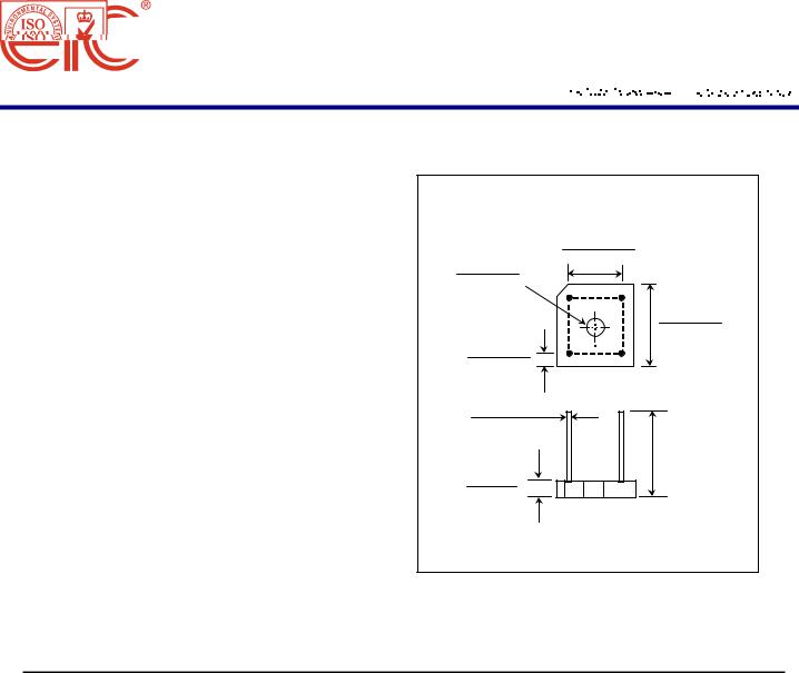
BR6
0.445 (11.30)
0.405 (10.30)
0.158 (4.00)
AC
0.142 (3.60)
0.62 (15.75)
0.58 (14.73)
0.127 (3.20)
0.047 (1.20)
AC
0.042 (1.06)
0.038 (0.96)
0.75 (19.1) Min.
0.27 (6.9)
0.23 (5.8)
Dimensions in inches and ( millimeters )
MAXIMUM RATINGS AND ELECTRICAL CHARACTERISTICS
Rating at 25 °C ambient temperature unless otherw ise specified.
Single phase, half w ave, 60 Hz, resistive or inductive load.
For capacitive load, derate current by 20%.
RATING |
|
SYMBOL |
BR600 |
BR601 |
BR602 |
BR604 |
BR606 |
BR608 |
BR610 |
UNITS |
|
|
|
|
|
|
|
|
|
|
|
Maximum Recurrent Peak Reverse Voltage |
VRRM |
50 |
100 |
200 |
400 |
600 |
800 |
1000 |
Volts |
|
|
|
|
|
|
|
|
|
|
|
|
Maximum RMS Voltage |
|
VRMS |
35 |
70 |
140 |
280 |
420 |
560 |
700 |
Volts |
|
|
|
|
|
|
|
|
|
|
|
Maximum DC Blocking Voltage |
|
VDC |
50 |
100 |
200 |
400 |
600 |
800 |
1000 |
Volts |
|
|
|
|
|
|
|
|
|
|
|
Maximum Average Forward Current Tc=50°C |
IF(AV) |
|
|
|
6.0 |
|
|
|
Amps. |
|
|
|
|
|
|
|
|
|
|
|
|
Peak Forward Surge Current, |
|
|
|
|
|
|
|
|
|
|
Single half sine wave Superimposed |
|
|
|
|
|
|
|
|
|
|
on rated load (JEDEC Method) |
|
IFSM |
|
|
|
200 |
|
|
|
Amps. |
|
|
|
|
|
|
|
|
|
|
|
Current Squared Time at t < 8.3 ms. |
I2t |
|
|
|
64 |
|
|
|
A2S |
|
Maximum Forward Voltage per Diode at IF =3 A. |
VF |
|
|
|
1.0 |
|
|
|
Volts |
|
|
|
|
|
|
|
|
|
|
|
|
Maximum DC Reverse Current |
Ta = 25 °C |
IR |
|
|
|
10 |
|
|
|
μA |
|
|
|
|
|
|
|
|
|
|
|
at Rated DC Blocking Voltage |
Ta = 100 °C |
IR(H) |
|
|
|
200 |
|
|
|
μA |
|
|
|
|
|
|
|
|
|
|
|
Typical Thermal Resistance (Note 1) |
RθJC |
|
|
|
8.0 |
|
|
|
°C/W |
|
|
|
|
|
|
|
|
|
|
|
|
Operating Junction Temperature Range |
TJ |
|
|
- 40 to + 150 |
|
|
°C |
|||
|
|
|
|
|
|
|
|
|
|
|
Storage Temperature Range |
|
TSTG |
|
|
- 40 to + 150 |
|
|
°C |
||
|
|
|
|
|
|
|
|
|
|
|
|
|
|
|
|
|
|
|
|
|
|
Notes : |
|
|
|
|
|
|
|
|
|
|
1. Thermal Resistance from junction to case w ith units mounted on a 2.6" x 1.4" x 0.06" THK |
|
|
|
|
|
|||||
(6.5cm.x 3.5cm.x 0.15cm.) Al. Plate. Heatsink. |
|
|
|
|
|
UPDATE : APRIL 23, 1998 |
||||
 Loading...