


1N5957A
EIC 1N5957A, 1N5956A, 1N5955A, 1N5954A, 1N5953A Datasheet
...
1N5913A - 1N595
7
A
SILICON ZENER DIODES
VZ : 3.3 - 240 Volts
PD : 1.5 Watts
FEATURES :
* Complete Voltage Range 3.3 to 200 Volts
* Low leakage current
MECHANICAL DATA
* Case : DO-41 Molded plastic
MAXIMUM RATINGS
Rating at 25
C ambient temperature unless otherwise specified
Note :
(1) TL = Lead temperature at 3/8 " (9.5mm) from body
(2) Valid provided that leads are kept at ambient temperature at a distance of 10 mm from case.
0255075100
125
150
175
T
LEAD TEMPERATURE (
C)
UPDATE : SEPTEMBER 9, 2000
1.5
Fig. 1 POWER TEMPERATURE DERATING CURVE
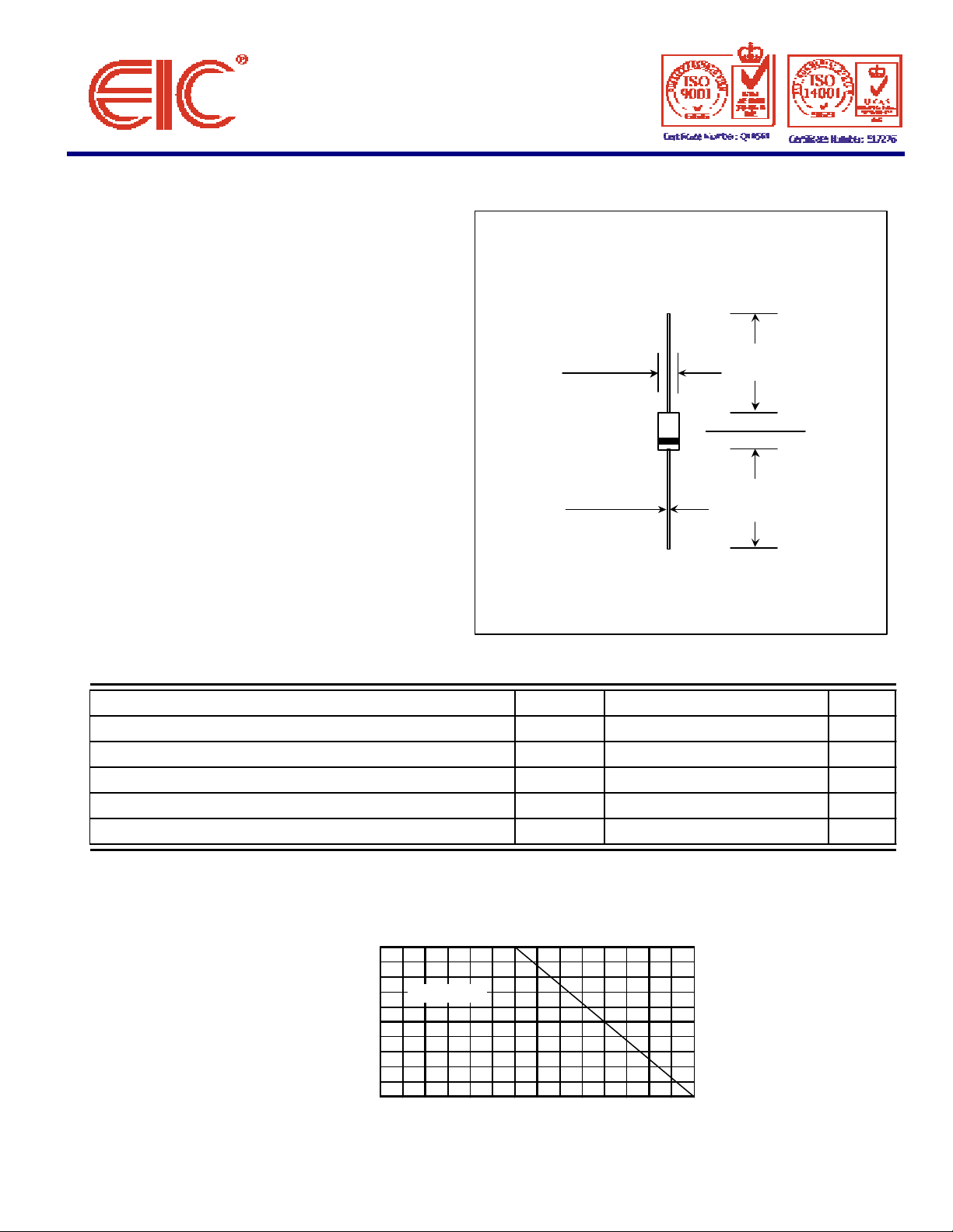
DO - 41
Dimensions in inches and ( millimeters )
* High peak reverse power dissipation
* High reliability
0.107 (2.7)
0.080 (2.0)
1.00 (25.4)
MIN.
0.205 (5.2)
0.166 (4.2)
* Epoxy : UL94V-O rate flame retardant
* Lead : Axial lead solderable per MIL-STD-202,
method 208 guaranteed
* Polarity : Color band denotes cathode end
* Mounting position : Any
* Weight : 0.339 gram
°
0.034 (0.86)
0.028 (0.71)
1.00 (25.4)
MIN.
Rating Symbol Value Unit
D
DC Power Dissipation at TL = 75 °C (Note1)
Maximum Forward Voltage at IF = 200 mA V
Maximum Thermal Resistance Junction to Ambient Air (Note2)
Junction Temperature Range T
Storage Temperature Range Ts - 55 to + 175 °
P
F
RθJA
J
1.5 Watts
1.5 Volts
130 K / W
- 55 to + 175
°
C
C
1.2
0.9
0.6
(WATTS)
0.3
PD, MAXIMUM DISSIPATION
L = 3/8" (9.5mm)
L,
°
 Loading...