

Page 1

Troubleshooting Guide
Eaton Hybrid Drive Systems MY08
TRTS1000 EN-US
October 2015
EH-8E306A-U
EH-8E306A-UPG
EH-8E306A-UP
EH-8E306A-CD
EH-8E306A-T
EH-6E606B-CD
Page 2

Page 3

Page 4

Table of Contents TRTS1000
Table of Contents
General Information
Warnings & Cautions. . . . . . . . . . . . . . . . . . . . . . . . . . 1
High-Voltage Warnings & Cautions . . . . . . . . . . . . 2
Insulated Rubber Glove Test and High-Voltage
Work Area . . . . . . . . . . . . . . . . . . . . . . . . . . . . . . . . . . 3
Insulated Rubber Glove Test. . . . . . . . . . . . . . . . . . 3
High-Voltage Work Area Requirements . . . . . . . . . 3
High-Voltage Service Shutdown and Power-Up
Procedure . . . . . . . . . . . . . . . . . . . . . . . . . . . . . . . . . . 4
High-Voltage Service Shutdown Procedures . . . . . 5
High-Voltage Service Power-Up Procedure . . . . . . 5
Diagnostic Tools/Service Publications. . . . . . . . . . . . . 6
Eaton Tools. . . . . . . . . . . . . . . . . . . . . . . . . . . . . . . 6
SPX/OTC To ols. . . . . . . . . . . . . . . . . . . . . . . . . . . . 6
Service Publications. . . . . . . . . . . . . . . . . . . . . . . . 7
Hybrid Diagnostic Procedure. . . . . . . . . . . . . . . . . . . . 8
Hybrid Component and Connector Locations. . . . . . . . 9
Transmission Wiring Connections . . . . . . . . . . . . . 9
Component Wiring Connections. . . . . . . . . . . . . . 11
Fault Code Retrieval and Clearing. . . . . . . . . . . . . . . . 13
View Active and Inactive Faults . . . . . . . . . . . . . . 13
Clear Inactive Faults. . . . . . . . . . . . . . . . . . . . . . . 13
Fault Code Isolation Procedure Index. . . . . . . . . . . . . 14
Symptom-Driven Diagnostics Index. . . . . . . . . . . . . . 18
Product Diagnostic Mode (PDM). . . . . . . . . . . . . . . . 19
PDM only works with the following Inactive
codes: . . . . . . . . . . . . . . . . . . . . . . . . . . . . . . . . . 19
Hybrid Light and Gear Display Descriptions. . . . . . . . 20
Red “Service” Light . . . . . . . . . . . . . . . . . . . . . . . 20
Amber “Check Hybrid” Light . . . . . . . . . . . . . . . . 20
Red “Stop Hybrid” Light. . . . . . . . . . . . . . . . . . . . 20
Blinking Amber “Check Hybrid” Light. . . . . . . . . . 20
“ST” in Gear Display. . . . . . . . . . . . . . . . . . . . . . . 20
“PD” in Gear Display . . . . . . . . . . . . . . . . . . . . . . 20
“CA” in Gear Display . . . . . . . . . . . . . . . . . . . . . . 21
“OS” in Gear Display . . . . . . . . . . . . . . . . . . . . . . 21
“F” in Gear Display. . . . . . . . . . . . . . . . . . . . . . . . 21
Dash “-” in Gear Display. . . . . . . . . . . . . . . . . . . . 21
Double Stars “**” in Gear Display . . . . . . . . . . . . 21
Double Dashes “- -” in Gear Display. . . . . . . . . . . 21
Blank Gear Display. . . . . . . . . . . . . . . . . . . . . . . . 21
Electrical Pretest Procedures
Power-Up Sequence Test. . . . . . . . . . . . . . . . . . . . . . 22
Electrical Pretest . . . . . . . . . . . . . . . . . . . . . . . . . . . . 25
Hybrid Electrical Pretest. . . . . . . . . . . . . . . . . . . . . . . 29
Fault Isolation Procedures
Fault Code 1 - Motor/Generator Current Sensor. . . . . 33
Fault Code 2 - Motor/Generator Temperature Sensor 38
Fault Code 3 - Motor/Generator Temperature . . . . . . 42
Fault Code 4 - Motor/Generator Rotation Speed
Sensor . . . . . . . . . . . . . . . . . . . . . . . . . . . . . . . . . . . . 48
Fault Code 5 - Motor/Generator AC Cable . . . . . . . . . 52
Fault Code 6 - No HCM Operation . . . . . . . . . . . . . . . 57
Fault Code 7 - Improper HCM Configuration . . . . . . . 60
Fault Code 8 - Loss of Switched Ignition Power
(HCM) . . . . . . . . . . . . . . . . . . . . . . . . . . . . . . . . . . . . 63
Fault Code 9 - Weak Battery Voltage . . . . . . . . . . . . . 66
Fault Code 10 - Low Battery Voltage (HCM). . . . . . . . 69
Fault Code 11 - No TECU Operation. . . . . . . . . . . . . . 72
Fault Code 12 - Improper TECU Configuration. . . . . . 75
Fault Code 14 - Invalid Shifter Range. . . . . . . . . . . . . 78
Fault Code 16 - High Integrity Link (HIL) Test . . . . . . 83
Fault Code 17 - Start Enable Relay. . . . . . . . . . . . . . . 89
Fault Code 18 - ECA Communication. . . . . . . . . . . . . 94
Fault Code 24 - J1939 HCM Message (TECU) . . . . . . 97
Fault Code 26 - Clutch Slip. . . . . . . . . . . . . . . . . . . . 101
Fault Code 27 - Clutch Disengagement . . . . . . . . . . 105
Fault Code 32 - Loss of Switched Ignition Power
(TECU). . . . . . . . . . . . . . . . . . . . . . . . . . . . . . . . . . . 108
Fault Code 33 - Low Battery Voltage (TECU) . . . . . . 111
Fault Code 34 - Weak Battery Voltage Fault (TECU). 114
Fault Code 35 - J1939 Communication Link (TECU) 117
Fault Code 36 - J1939 Engine Message (TECU). . . . 122
Fault Code 37 - Power Supply (TECU) . . . . . . . . . . . 125
Fault Code 38 - Battery Fan Relay . . . . . . . . . . . . . . 129
Fault Code 39 - Heat Exchanger Relay . . . . . . . . . . . 135
Fault Code 40 - Cooling Pump Relay . . . . . . . . . . . . 140
Fault Code 47 - J1939 ABS Message (HCM) . . . . . . 146
Fault Code 48 - J1939 Transmission Message
(HCM) . . . . . . . . . . . . . . . . . . . . . . . . . . . . . . . . . . . 149
© 2015 Eaton. All rights reserved
Page 5

TRTS1000 T able of Contents
Fault Isolation Procedures - continued
Fault Code 49 - J1939 Engine Message (HCM) . . . . 153
Fault Code 50 - J1939 Body Controller Message
(HCM) . . . . . . . . . . . . . . . . . . . . . . . . . . . . . . . . . . . 156
Fault Code 51 - Rail Position Sensor . . . . . . . . . . . . 159
Fault Code 52 - Gear Position Sensor . . . . . . . . . . . 164
Fault Code 53 - DC/DC Converter. . . . . . . . . . . . . . . 169
Fault Code 54 - DC/DC Converter Output Voltage . . 172
Fault Code 56 - Input Shaft Speed Sensor. . . . . . . . 177
Fault Code 58 - Output Shaft Speed Sensor. . . . . . . 181
Fault Code 59 - J1939 Communication Link (HCM). 18 5
Fault Code 60 - CAN Communication Link (HCM) . . 190
Fault Code 61 - Rail Select Motor . . . . . . . . . . . . . . 194
Fault Code 63 - Gear Select Motor. . . . . . . . . . . . . . 197
Fault Code 64 - ECA Fault . . . . . . . . . . . . . . . . . . . . 201
Fault Code 65 - ECA Speed Sensor . . . . . . . . . . . . . 204
Fault Code 66 - ECA Battery Voltage . . . . . . . . . . . . 208
Fault Code 67 - ECA Ignition Voltage. . . . . . . . . . . . 211
Fault Code 70 - Engine Failed to Respond (HCM) . . 215
Fault Code 71 - Failed to Disengage a Gear . . . . . . . 218
Fault Code 72 - Failed to Select Rail. . . . . . . . . . . . . 222
Fault Code 73 - Failed to Engage a Gear. . . . . . . . . . 225
Fault Code 74 - Engine Failed to Respond (TECU). . 228
Fault Code 75 - Power Down in Gear. . . . . . . . . . . . 231
Fault Code 76 - High Voltage Battery 1 Potential
Voltage. . . . . . . . . . . . . . . . . . . . . . . . . . . . . . . . . . . 234
Fault Code 77 - High Voltage Battery 2 Potential
Voltage. . . . . . . . . . . . . . . . . . . . . . . . . . . . . . . . . . . 237
Fault Code 78 - High Voltage Battery 1 Current . . . . 240
Fault Code 79 - High Voltage Battery 2 Current . . . . 243
Fault Code 82 - High Voltage Battery 1 Temperature 246
Fault Code 83 - Invalid Shifter Range. . . . . . . . . . . . 250
Fault Code 84 - Shift Control Device Not Configured 255
Fault Code 85 - Shift Control Device Incompatible. . 261
Fault Code 86 - High Voltage Battery 2 Temperature 265
Fault Code 87 - CAN ECA Message (HCM). . . . . . . . 269
Fault Code 88 - CAN Inverter Message (HCM). . . . . 273
Fault Code 89 - CAN BCU 1 Message (HCM). . . . . . 277
Fault Code 90 - CAN BCU 2 Message (HCM). . . . . . 281
Fault Code 91 - APG Unit 1 CAN . . . . . . . . . . . . . . . 285
Fault Code 95 - 12-Volt Cranking Relay. . . . . . . . . . 289
Fault Code 96 - Accelerator Pedal Offset . . . . . . . . . 293
Fault Code 97 - PTO Engagement . . . . . . . . . . . . . . 296
Fault Code 101 - High Voltage Battery 1 . . . . . . . . . 303
Fault Code 102 - High Voltage Battery 2 . . . . . . . . . 307
Fault Code 103 - High Voltage Battery 1 Control
Unit Communication . . . . . . . . . . . . . . . . . . . . . . . . 311
Fault Code 104 - High Voltage Battery 2 Control
Unit Communication . . . . . . . . . . . . . . . . . . . . . . . . 314
Fault Code 105 - High Voltage Battery 1 Control
Unit . . . . . . . . . . . . . . . . . . . . . . . . . . . . . . . . . . . . . 318
Fault Code 106 - High Voltage Battery 2 Control
Unit . . . . . . . . . . . . . . . . . . . . . . . . . . . . . . . . . . . . . 322
Fault Code 107 - High Voltage Battery Leak
Detection . . . . . . . . . . . . . . . . . . . . . . . . . . . . . . . . . 325
Fault Code 108 - High Voltage Battery 1 Control
Unit Power Supply. . . . . . . . . . . . . . . . . . . . . . . . . . 334
Fault Code 109 - High Voltage Battery 2 Control
Unit Power Supply. . . . . . . . . . . . . . . . . . . . . . . . . . 338
Fault Code 110 - Inverter. . . . . . . . . . . . . . . . . . . . . 342
Fault Code 111 - Inverter Communication. . . . . . . . 345
Fault Code 112 - Inverter Voltage . . . . . . . . . . . . . . 349
Fault Code 113 - Inverter Current . . . . . . . . . . . . . . 353
Fault Code 114 - Inverter Power Supply . . . . . . . . . 358
Fault Code 115 - Inverter Temperature . . . . . . . . . . 362
Fault Code 116 - High Voltage Relays . . . . . . . . . . . 367
Fault Code 117 - BCU Relay Cut Request. . . . . . . . . 374
Fault Code 118 - Auxiliary High-Voltage Relay
Control Circuit . . . . . . . . . . . . . . . . . . . . . . . . . . . . . 379
Fault Code 120 - APG Unit 1 AC Voltage . . . . . . . . . 385
Fault Code 122 - APG UNIT 1 Output . . . . . . . . . . . . 388
Fault Code 123 - APG Unit 1 High Voltage Battery. . 393
Fault Code 125 - APG Unit 1 Over Temperature. . . . 396
Fault Code 126 - APG Unit 1 Configuration . . . . . . . 399
Fault Code 127 - APG Unit 1 Ambient Air
Over Temperature . . . . . . . . . . . . . . . . . . . . . . . . . . 402
Fault Code 128 - APG Unit 1 Ambient Air
Temperature Sensor . . . . . . . . . . . . . . . . . . . . . . . . 405
Fault Code 129 - APG Unit 1 Communication . . . . . 408
Fault Code 131 - APG Unit 1 Configuration Error. . . 412
2015.10.19
© 2015 Eaton. All rights reserved
ii
Page 6

Table of Contents TRTS1000
Symptom Procedures
Front Box Test . . . . . . . . . . . . . . . . . . . . . . . . . . . . . 416
Engine Crank Test . . . . . . . . . . . . . . . . . . . . . . . . . . 420
Hybrid Performance Test. . . . . . . . . . . . . . . . . . . . . 424
ServiceRanger Test . . . . . . . . . . . . . . . . . . . . . . . . . 427
Gear Engagement Test. . . . . . . . . . . . . . . . . . . . . . . 432
ePTO Test . . . . . . . . . . . . . . . . . . . . . . . . . . . . . . . . 436
Appendix
Wiring Diagrams . . . . . . . . . . . . . . . . . . . . . . . . . . . 444
Hybrid Tr ansmission ECU System Harness . . . . 445
Connector Pin Descriptions . . . . . . . . . . . . . . . . . . . 446
Hybrid and Transmission Connector Pins . . . . . 446
TECU and HCM Connectors . . . . . . . . . . . . . . . . 446
Transmission Controller 38-Way
(Vehicle Interface Connector). . . . . . . . . . . . . . . 447
Hybrid Controller 38-Way
(Vehicle Interface Connector). . . . . . . . . . . . . . . 448
Hybrid Controller 38-Way
(Hybrid System Interface Connector). . . . . . . . . 449
Inverter connectors . . . . . . . . . . . . . . . . . . . . . . 450
Inverter 56-Way Connector . . . . . . . . . . . . . . . . 451
Power Electronics Carrier (PEC) Connectors . . . 452
PEC 19-Way Connector . . . . . . . . . . . . . . . . . . . 453
PEC High-Voltage (DC) Connector to Inverter . . 453
PEC High-Voltage (DC) Connector to DC/DC
Converter . . . . . . . . . . . . . . . . . . . . . . . . . . . . . . 453
Inverter High-Voltage (AC) Connector . . . . . . . . 453
Inverter High-Voltage (DC) Connector . . . . . . . . 453
Electric Clutch Actuator (ECA) Connectors. . . . . 454
ECA 3-Way Connector . . . . . . . . . . . . . . . . . . . . 454
ECA 8-Way Connector . . . . . . . . . . . . . . . . . . . . 454
Motor/Generator Connectors . . . . . . . . . . . . . . . 455
Typical DC/DC Converter Circuit. . . . . . . . . . . . . 457
iii
© 2015 Eaton. All rights reserved
2015.10.19
Page 7
TRTS1000 General Information | Warnings & Cautions
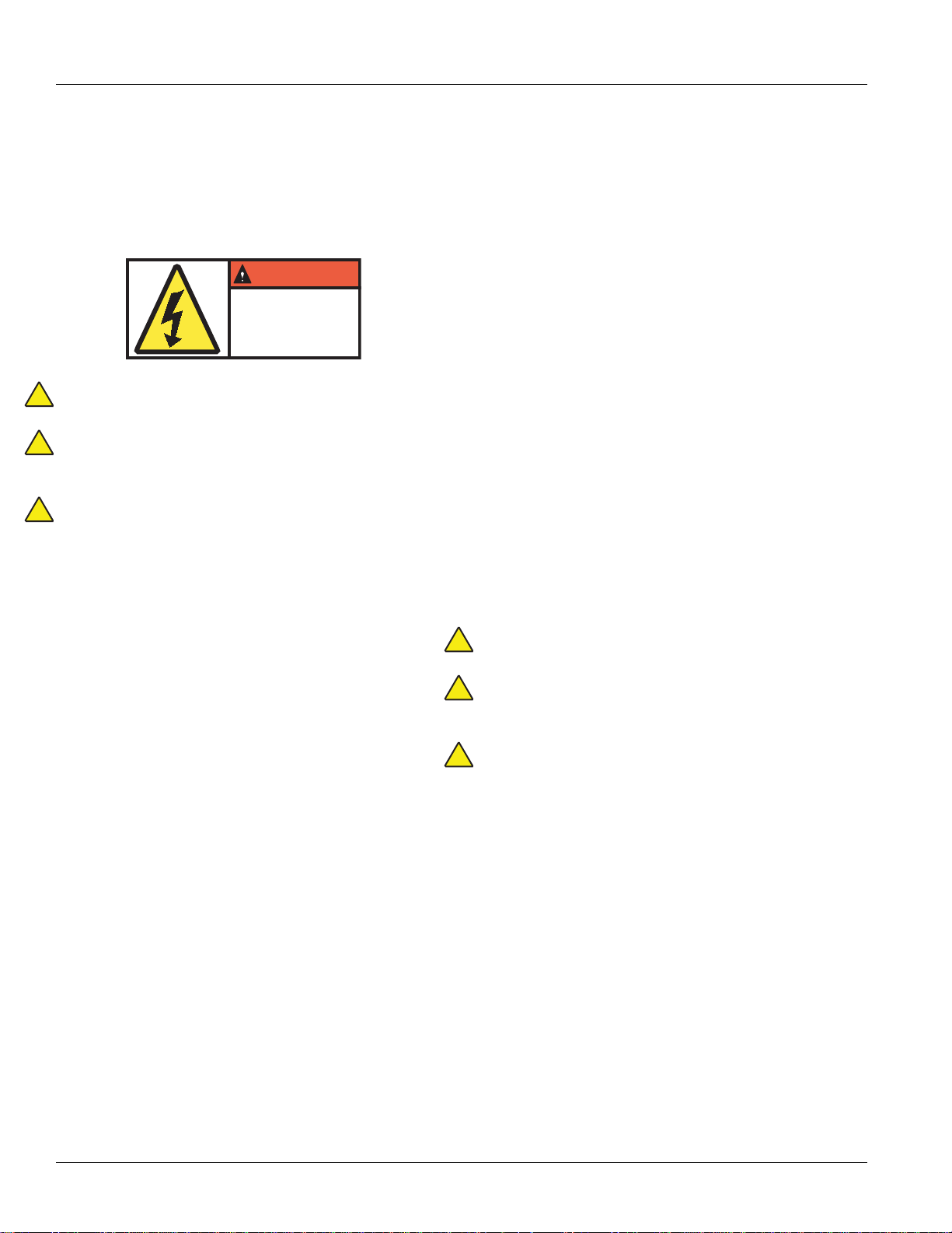
DANGER
HAZARDOUS VOLTAGE
You will be severely injured or killed
if you do not follow the procedure.
Components marked with
DANGER High Voltage should be
avoided. Service must be
performed by qualified personnel only.
!
!
!
!
!
!
Warnings & Cautions
Throughout this service manual there are paragraphs that
are marked with a title of Danger, Warning, or Caution.
These special paragraphs contain specific safety
information and must be read, understood, and heeded
before continuing the procedure or performing the step(s).
Danger: Danger indicates you will be severely injured or
killed if do not follow the indicated procedure.
Warning: Warning indicates an immediate hazard, which
could result in severe personal injury if you do not follow
the indicated procedure.
Caution: Caution indicates vehicle or property damage
could occur if you do not follow the indicated procedure.
Note: Note indicates additional detail that will aid in the
diagnosis or repair of a component/system.
Follow the specified procedures in the indicated order to
avoid personal injury:
1. If the high-voltage cones are around the vehicle
and the lockout is installed on the PEC, the only
person that should be allowed to start the vehicle is
the person who signed the lockout tag.
2. Before working on a vehicle or leaving the cab
while the engine is running, you should place the
shift lever in “N” set the parking brake, and block
the wheels.
3. For safety reasons, always engage the service
brakes prior to selecting gear positions from “N.”
4. Before starting a vehicle always be seated in the
driver's seat, select “N” on the shift control, and set
the parking brakes.
5. In vehicles with ePTO, the engine and/or
Motor/Generator can start in ePTO mode. Never
perform any maintenance or work on vehicle, while
in this mode.
6. 12-Volt Battery positive (+) and negative (-) must
be disconnected prior to any welding on any Hybrid
equipped vehicle.
Caution: Follow the specified procedures in the indicated
order to avoid equipment malfunction or damage.
Caution: Do not release the parking brake or attempt to
select a gear until the air pressure is at the
correct level.
Caution: T o avoid damage to the transmission during
towing place the shift lever in “N” and lift the drive
wheels off the ground or disconnect the driveline.
2015.10.19
© 2015 Eaton. All rights reserved
1
Page 8
Warnings & Cautions | General Information TRTS1000
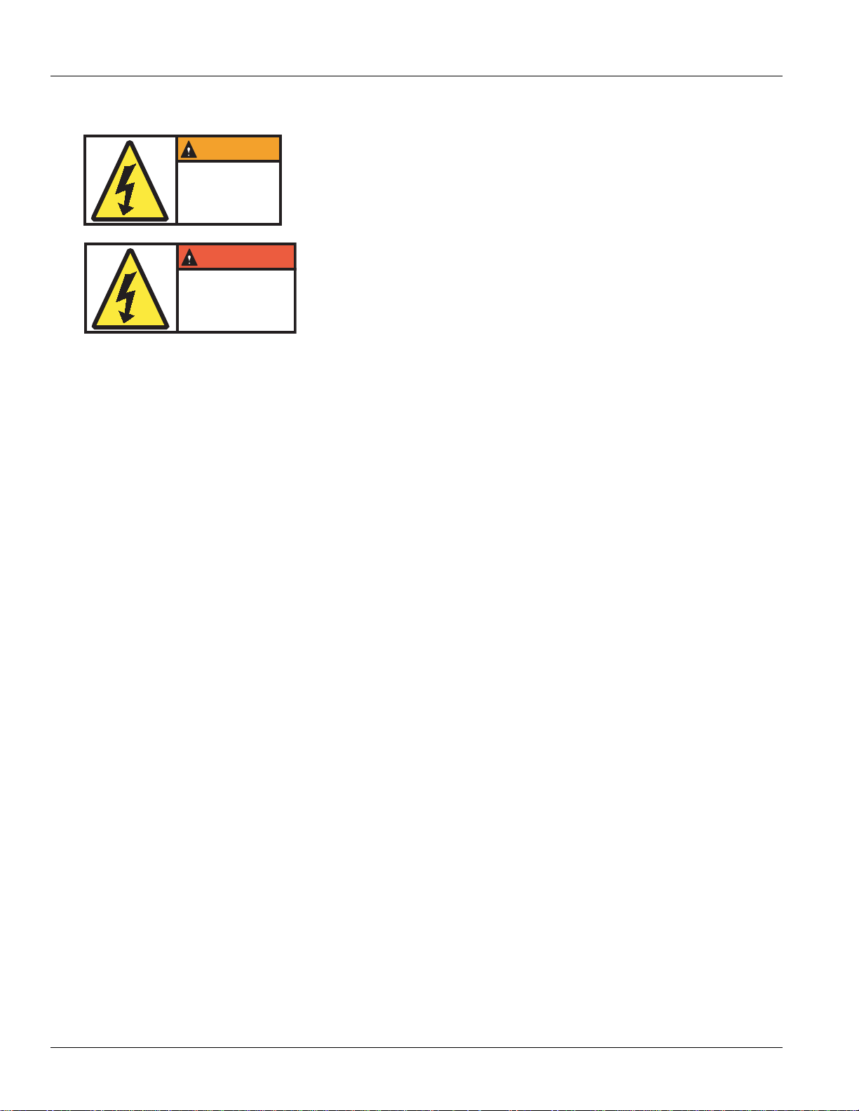
WARNING
To reduce risk of possible serious
injury (Shock, Burn or Death):
Components marked with High
Voltage should be avoided.
Service must be performed by
qualified personnel only.
HAZARDOUS VOLTAGE
DANGER
HAZARDOUS VOLTAGE
You will be severely injured or killed
if you do not follow the procedure.
Components marked with
DANGER High Voltage should be
avoided. Service must be
performed by qualified personnel only.
High-Voltage Warnings & Cautions
• Use CO2 or Dry Chemical Fire Extinguishers.
• The high-voltage wiring is covered in orange
insulation or convoluted tubing and marked with
warning labels at the connectors.
• All Eaton® Hybrid Diesel/Electric vehicles will be
marked 'Hybrid' on the outside of the vehicle, along
with the shift label on the dash.
• Refer to OEM for specific location of chassis
mounted hybrid components.
• Do NOT cut into the orange high-voltage cables.
• Do NOT cut into or open the PEC.
• Do NOT cut into or open the DC/DC Converter.
• Do NOT cut into or open the Inverter.
A buffer zone must be set up and high-voltage insulated
rubber gloves (class 0 with leather protectors) are required
prior to working on high-voltage. Failure to follow these
instructions may result in severe personal injury or death.
The rubber-insulated gloves that must be worn while
working on the high-voltage system are class 0 with leather
protectors. The rubber gloves should be tested before
EVERY use following the rubber insulation gloves testing
procedure found in “Diagnostic Tools/Service Publications”
on page 6. Failure to follow these instructions may result in
severe personal injury or death.
Before inspecting or working on any high-voltage cables or
components the “High-Voltage Service Shutdown and
Power-Up Procedure” on page 4 should be followed. Failure
to follow these instructions may result in severe personal
injury or death.
The Lockout and Tagout devices should only be removed by
the technician that placed the Lockout and Tagout devices
on the vehicle. Failure to follow these instructions may
result in severe personal injury or death.
High-voltage rubber insulated gloves (class 0 with leather
protectors) must be worn when working on any
high-voltage cables. The “High-Voltage Service Shutdown
and Power-Up Procedure” on page 4 must be followed prior
to removing any high-voltage cables. Failure to follow these
instructions may result in severe personal injury or death.
High-voltage cables and wiring are orange and contain a
warning label at the connectors. High-voltage components
are marked with a label. High-voltage rubber insulated
gloves (class 0 with leather protectors) must be used when
working on any of these components. Failure to follow
these instructions may result in severe personal injury
or death.
2
© 2015 Eaton. All rights reserved
2015.10.19
Page 9

TRTS1000 General Information | Insulated Rubber Glove T est and High-V oltage W ork Area
!
!
Insulated Rubber Glove Test and High-Voltage Work Area
Insulated Rubber Glove Test
Warning: The rubber-insulated gloves that must be worn
while working on the high-voltage system are class 0 with
leather protectors. The rubber gloves should be tested
before EVERY use following the rubber insulation gloves
testing procedure found in “Diagnostic Tools/Service Publications” on page 6. Failure to follow these instructions may
result in severe personal injury or death.
The insulated rubber gloves that must be worn while
working on the high-voltage system are class 0 rated. They
must be inspected before each use and must always be
worn in conjunction with the leather outer glove. Any hole
in the insulated rubber glove is a potential entry point for
high-voltage.
• Roll the glove up from the open end until the lower
portion of the glove begins to balloon from the
resulting air pressure. If the glove leaks any air it
must not be used.
• The gloves should not be used if they exhibit any
signs of wear and tear.
• The leather gloves must always be worn over the
rubber insulating gloves to protect them.
High-Voltage Work Area Requirements
Warning: A buffer zone must be set up and high-voltage
insulated rubber gloves (class 0 with leather protectors) are
required prior to working on any high voltage. Failure to follow these instructions may result in severe personal injury
or death.
The buffer zone is required only when working on the
high-voltage DC or AC systems and is called out both in the
“High-Voltage Service Shutdown and Power-Up Procedure”
on page 4 and the individual repair procedure.
• Position the vehicle in the service bay.
• Position 4 orange cones around the corners of the
vehicle to mark off a 3' (1m) perimeter around the
vehicle.
• Do not allow any unauthorized personnel into the
buffer zone during repairs involving high voltage.
Only personnel trained for service on the
high-voltage system are to be permitted in the
buffer zone.
• The rubber insulating gloves must be class 0 and
meet all of the American Safety Testing Materials
standards.
2015.10.19
© 2015 Eaton. All rights reserved
3
Page 10

High-Voltage Service Shutdown and Power-Up Procedure | General Information TRTS1000
WARNING
To reduce risk of possible serious
injury (Shock, Burn or Death):
Components marked with High
Voltage should be avoided.
Service must be performed by
qualified personnel only.
HAZARDOUS VOLTAGE
DANGER
HAZARDOUS VOLTAGE
You will be severely injured or killed
if you do not follow the procedure.
Components marked with
DANGER High Voltage should be
avoided. Service must be
performed by qualified personnel only.
High-Voltage Service Shutdown and Power-Up Procedure
A buffer zone must be set up and ASTM Class 0 electrical
insulating rubber gloves with leather protectors are
required prior to working on high-voltage. Failure to follow
these instructions may result in severe personal injury or
death.
The rubber-insulated gloves that must be worn while
working on the high-voltage system are class 0 with leather
protectors. The rubber gloves should be tested before
EVERY use following the rubber insulation gloves testing
procedure found in the “Tool Specification” section. Failure
to follow these instructions may result in severe personal
injury or death.
Before inspecting or working on any high-voltage cables or
components this “High-Voltage Service Shutdown
Procedure” should be followed. Failure to follow these
instructions may result in severe personal injury or death.
The lockout tagout devices should only be removed by the
technician that placed the lockout tagout devices on the
vehicle. Failure to follow these instructions may result in
severe personal injury or death.
ASTM Class 0 electrical insulating rubber gloves with
leather protectors must be worn when working on any
high-voltage cables. This “High-Voltage Service Shutdown
Procedure” must be followed prior to removing any
high-voltage cables. Failure to follow these instructions
may result in severe personal injury or death.
High-voltage cables and wiring are orange and contain a
warning label at the connectors. High-voltage components
are marked with a label. ASTM Class 0 electrical insulating
rubber gloves with leather protectors must be used when
working on any of these components. Failure to follow
these instructions may result in severe personal injury
or death.
4
© 2015 Eaton. All rights reserved
2015.10.19
Page 11
TRTS1000 General Information | High-Voltage Service Shutdown and Power-Up Procedure
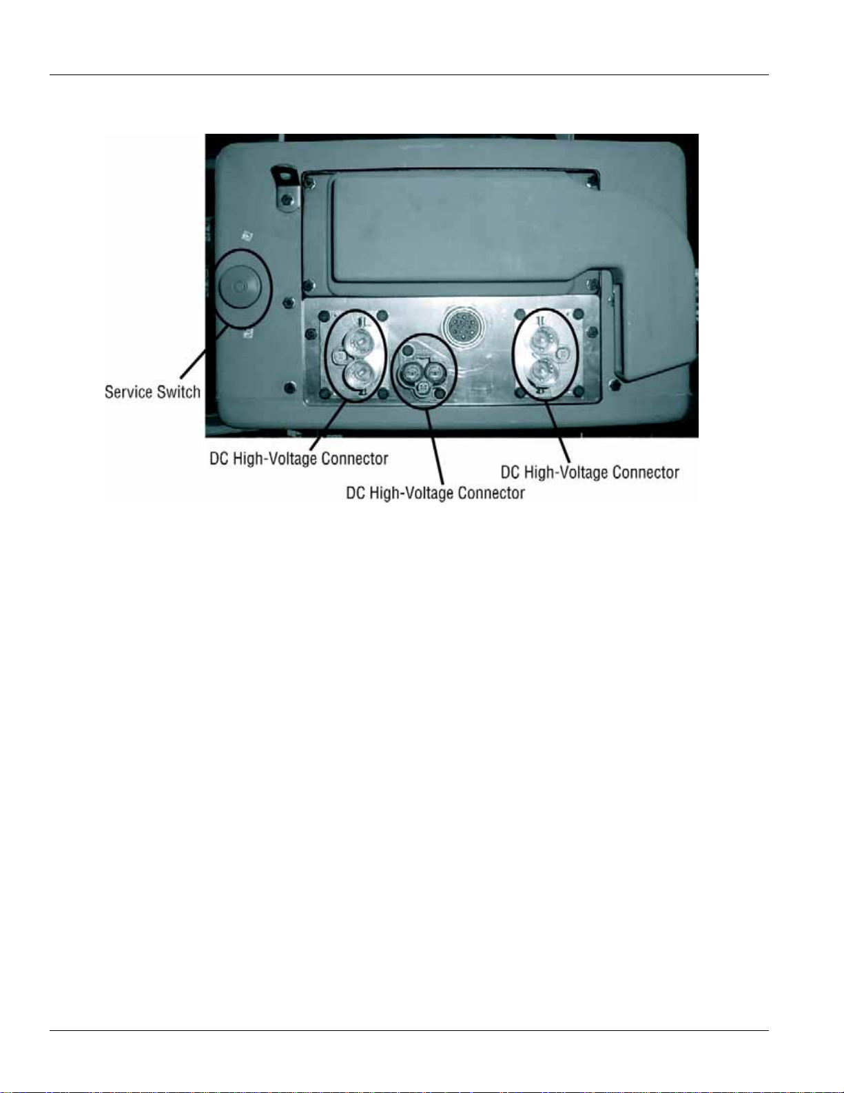
High-Voltage Service Shutdown
Procedures
1. Follow “High-Voltage Work Area” procedure.
2. Locate the red PEC Service Switch on the front of
the PEC and push switch off.
3. Remove the Service Switch Cover and install the
Lockout Bracket (J48506).
4. Fasten tag to the Lockout Bracket.
5. Ensure the PEC Service Switch can not move from
the off position.
6. Allow the system to set for a minimum of 5
minutes to discharge high voltage.
7. Connect ServiceRanger and view the Data Monitor
PID 116 called “High-Voltage Battery Potential.”
Use SPN 520323 for J1939 connection “Battery
Voltage RB” (Relay Box).
8. The voltage should be 30 volts or less. If the
voltage is above 30 volts, do not work on the
vehicle and contact Eaton® at 1-800-826-HELP
(4357).
9. Turn ignition key off and proceed to repair or
troubleshooting step.
Note: The voltage drops to zero when the key is off.
High-Voltage Service Power-Up
Procedure
1. Install all high-voltage connectors into their locked
positions.
2. If you are the person working on the vehicle,
remove the Lockout Bracket and tag.
3. Reinstall the Lockout Bracket over the Service
Switch.
4. Pull the Service Switch out and let vehicle set for 2
minutes.
5. Start vehicle when appropriate.
2015.10.19
© 2015 Eaton. All rights reserved
5
Page 12

Diagnostic Tools/Service Publications | General Information TRTS1000
Diagnostic Tools/Service Publications
Eaton Tools
• Visit Roadranger.com
Tool Description
ServiceRanger version 3 ServiceRanger PC based Diagnostic Tool
SPX/OTC Tools
• Contact SPX / OTC at (800) 328-6657
Tool Description
J49818 Eaton Hybrid Tool Safety Kit - Basic PPE (Items listed below can be ordered separately)
J48603 ASTM Class 0 electrical insulating rubber gloves with leather protectors (1000 volt)
J48605 Hybrid Safety Cones (set of 4)
J48506 Lockout Switch Plate
J48906 Lockout Tags (per 25)
Tool Description
J49819 Eaton Hybrid Tool Safety Kit - Basic Plus PPE (Items listed below can be ordered separately)
J48603 ASTM Class 0 electrical insulating rubber gloves with leather protectors (1000 volt)
J48605 Hybrid Safety Cones (set of 4)
J48506 Lockout Switch Plate
J48906 Lockout Tags (per 25)
J48907 Orange Magnetic Sign
J48608 Hybrid Non-Conductive Safety Pole
J48908 Glove Bag
6
© 2015 Eaton. All rights reserved
2015.10.19
Page 13

TRTS1000 General Information | Diagnostic Tools/Service Publications
Misc. Service Tools Items listed below are ordered separately
J48624 Nexiq USB-Link Communication Adapter
J43318-A* Pin Adapter Kit - Interface Harness Diagnostics
J48735* Alignment Pins - Hybrid Motor/Gen to Transmission Main Case
AMB-45* Digital Megohmmeter - High-Voltage Leakage Detection
J49111* Clutch Alignment Tool
J46708* Fluke Digital Multimeter
J48505 Input Shaft Turning Socket
J48507 Lifting Fixture - Power Electronics Carrier
J48502 Jack Adapter Plate - Hybrid Drive Unit
5019 Transmission Jack - Low Lift
5078 Transmission Jack - High Lift
J48577 Engine/Transmission Stand Adapter Plate - Hybrid Drive Unit
J29109-A Engine/Transmission Stand - 6000 lb. Rating
Tool Description
J48893 Hybrid PPE / Service Tool Kit (includes J49819 kit and items from Miscellaneous Service Tools
highlighted with *)
Service Publications
• Visit Roadranger.com
TRSM1000 Service Manual (covers external components on transmission and Hybrid components)
TRSM0110 Service Manual (covers internal transmission repairs only)
TRTS1000 Troubleshooting Guide
TRDR1000 Drivers Instructions
TRDR1110 First Responder Guide
CLMT-0365 Eaton 365 mm Clutch Installation Procedure
2015.10.19
© 2015 Eaton. All rights reserved
7
Page 14

Hybrid Diagnostic Procedure | General Information TRTS1000
Key ON
Retrieve Active Faults
with ServiceRanger
Active Codes?
Yes
Go to "Fault Code Isolation Procedure
Index" (page 14)
No
Does Gear Display
Show an "N"?
Does Engine Crank?
No
Yes
No
Yes
If equipped, does
vehicle operate
normal in ePTO mode?
No
Go to "ePTO Test”
(page 436)
Yes
If a mode other than neutral is selected does
transmission engage a gear? NOTE: Service
Brake must be applied prior to selecting a gear
No
Yes
Is vehicle acceleration
performance acceptable?
No
Yes
Clear faults and
operate vehicle based
on customers
concern
Inactive Faults = Go
to "Product
Diagnostic Mode (PDM)"
(page 19)
Active Faults = Go to
"Fault Code Isolation
Procedure Index"
(page 14)
No Fault = Test
Complete
Is Red "Stop Hybrid" or
Amber “Check Hybrid”
light blinking?
Yes
No
Go to “Hybrid Light and
Gear Display Descriptions”
(page 20)
Go to “Hybrid Light and
Gear Display Descriptions”
(page 20)
Go to “Gear Engagement
Test” (page 432)
Will vehicle move
from a stop?
Yes
No
Note: If ServiceRanger fails
to communicate, go to
“ServiceRanger Test”
(page 427)
Go to “Engine Crank
Test” (page 420)
Go to "Hybrid
Performance Test"
(page 424)
Go to "Gear Engagement Test”
if solid “N” is displayed
(page 432)
Go to “Front Box Test” is
flashing gear number is
displayed (page 416)
Hybrid Diagnostic Procedure
8
© 2015 Eaton. All rights reserved
2015.10.19
Page 15

TRTS1000 General Information | Hybrid Component and Connector Locations
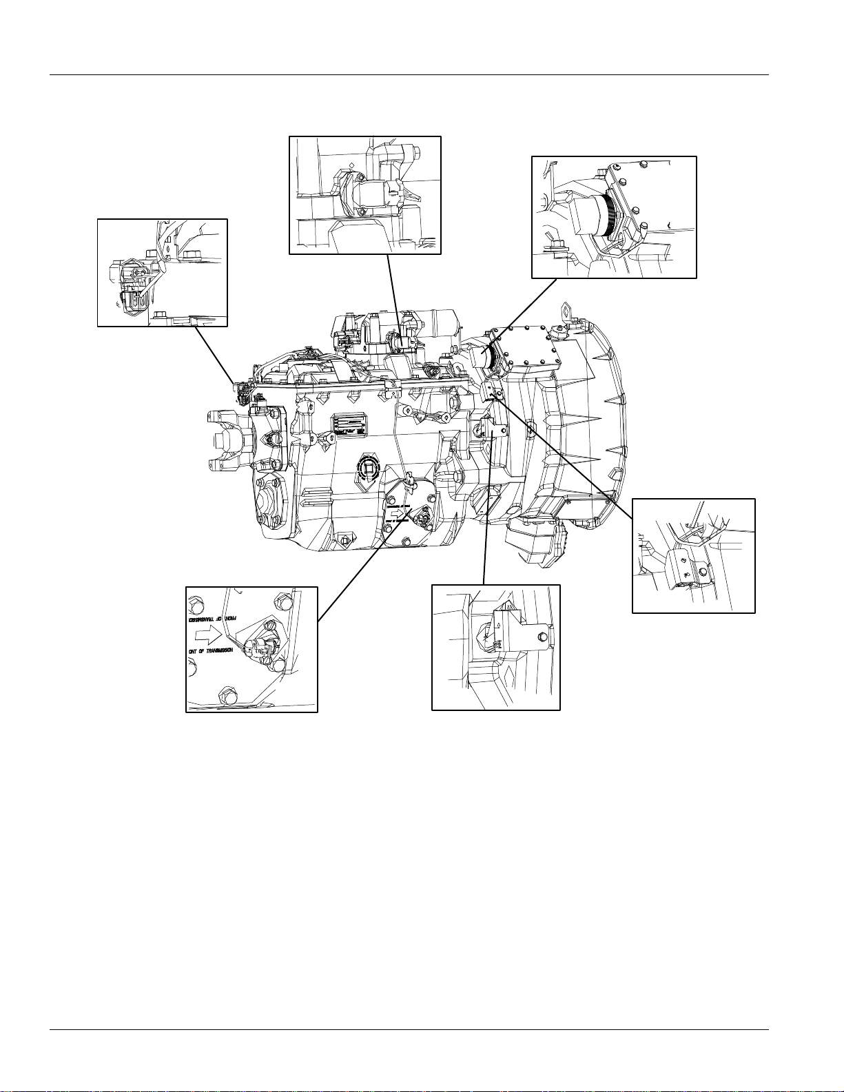
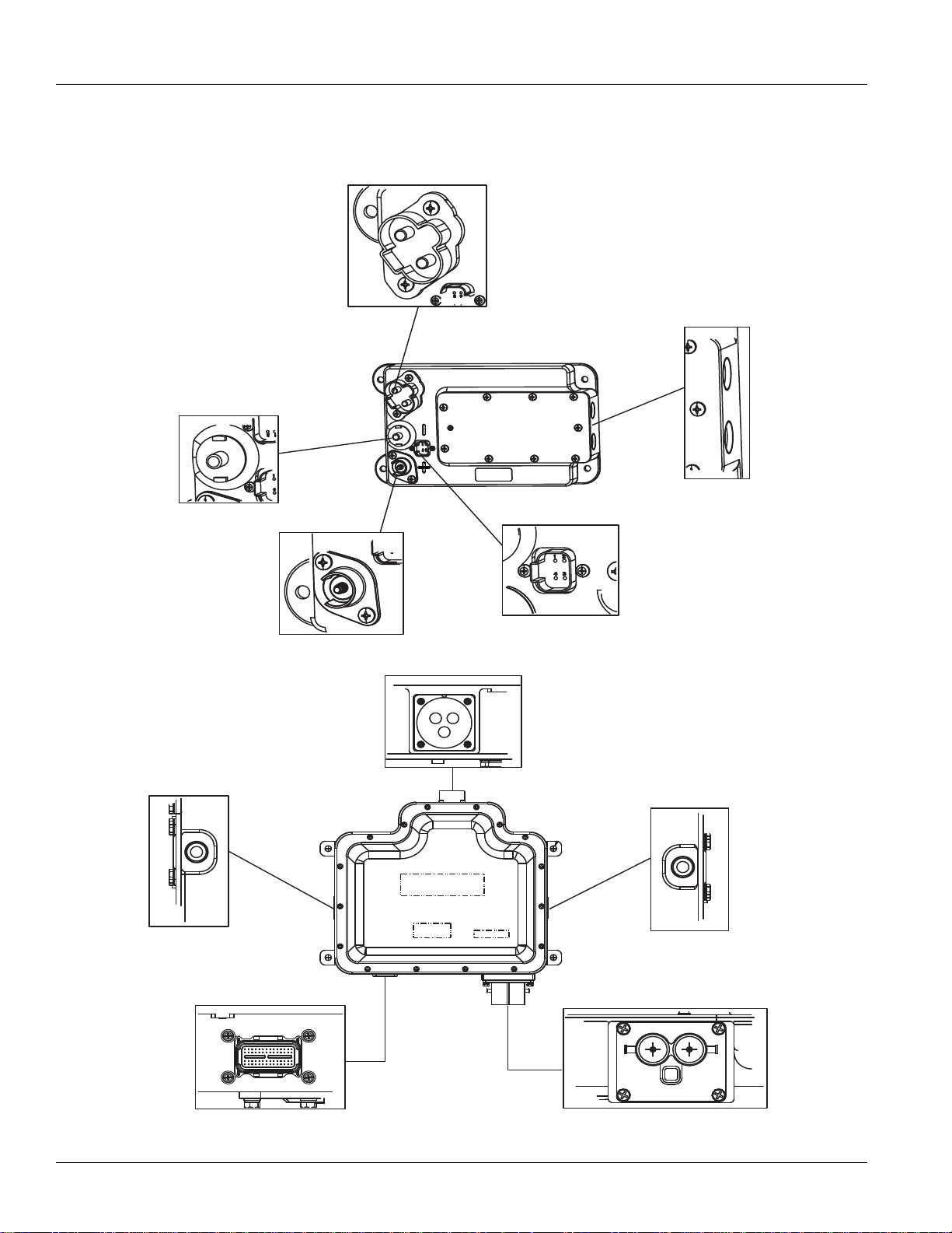
Hybrid Component and Connector Locations
Transmission Wiring Connections
Rail Position Sensor
Output Shaft Speed Sensor
Electronic Clutch Actuator
Top: 3-Way Connector
Bottom: 8-Way Connector
Transmission Electronic Control Unit (TECU)
Left: 38-Way Vehicle Connector
Right: 38-Way System Connector
Hybrid Control Module (HCM)
Left: 38-Way System Connector
Right: 38-Way Vehicle Connector
2015.10.19
© 2015 Eaton. All rights reserved
9
Page 16
Hybrid Component and Connector Locations | General Information TRTS1000
Gear Position Sensor
High-Voltage 3-Way AC Connector
Motor/Generator
Resolver Connector
Motor/Generator
Temperature Connector
Input Shaft Speed Sensor
Transmission Diagnostic Port
10
© 2015 Eaton. All rights reserved
2015.10.19
Page 17
TRTS1000 General Information | Hybrid Component and Connector Locations
12V DC(-)
High Voltage DC Connector
Top: DC(-)
Bottom: (DC(+)
OEM Connection
DC/DC Converter
HIgh Voltage 3-Way AC Connector
Low Voltage 56-Way Connector
High-Voltage DC Connector to PEC
Inverter
Coolant Ports
12V DC(+)
(-)
(+)
Coolant Port Inlet
Coolant Port Outlet
Component Wiring Connections
2015.10.19
© 2015 Eaton. All rights reserved
11
Page 18
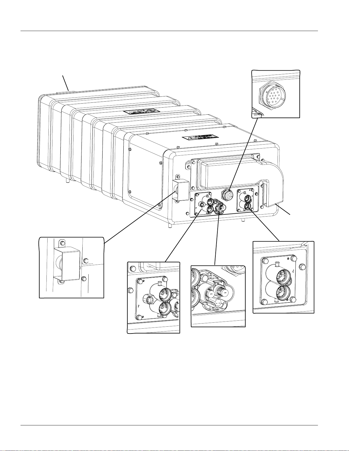
Hybrid Component and Connector Locations | General Information TRTS1000
Red Service Switch with Cover
DC Connector
to Inverter
DC Connector to DC/DC
Converter (Optional)
DC Connector to
APG (Optional)
Air Exhaust
(not shown)
19-Pin Low-Voltage Connector
Air Intake
Power Electronics Carrier (PEC)
12
© 2015 Eaton. All rights reserved
2015.10.19
Page 19

TRTS1000 General Information | Fault Code Retrieval and Clearing
Fault Code Retrieval and Clearing
All Eaton® hybrid systems require ServiceRanger for all
diagnostics. T o view fault codes or to clear them, follow the
procedures below.
View Active and Inactive Faults
1. Connect ServiceRanger to the 9-Way Diagnostic
Connector.
2. Go to the “Tools” menu and select the
“Communication” tab.
3. Select the appropriate communication device for
J1587 and J1939.
4. Select “Connect” on the main page.
5. Select the “View Fault Codes” tab.
Note: Initial use requires all steps; however subsequent
uses require only Step 4 and Step 5.
Clear Inactive Faults
1. Connect ServiceRanger to the 9-Way Diagnostic
Connector.
2. Go to the “Tools” menu and select the
“Communication” tab.
3. Select the appropriate communication device for
J1587 and J1939.
4. Select “Connect” on the main page.
5. Select the “View Fault Codes” tab.
6. Select the “Clear Faults” button.
Note: Initial use requires all steps, however
subsequent uses require only Step 4 and Step 5.
2015.10.19
© 2015 Eaton. All rights reserved
13
Page 20

Fault Code Isolation Procedure Index | General Information TRTS1000
Fault Code Isolation Procedure Index
Fault Code FMI Description Page Number
1 0, 6 Motor/Ge nerat or Current Sensor
2 3 Motor/Generator Temperature Sensor
3 0 Motor/Generator Temperature
4 0, 2, 22–27 Motor/Generator Rotation Speed Sensor
5 22–29 Motor/Generator AC Cable
6 12 No ECU Operation (HCM)
7 13 Improper ECU Configuration (HCM)
8 4 Loss of Switched Ignition Power (HCM)
9 14 Weak Battery Voltage (HCM)
10 4 Low Battery Voltage (HCM)
11 12 No ECU Operation (TECU)
12 13 Improper ECU Configuration (TECU)
14 2, 3, 4 Invalid Shifter Range
16 2 High Integrity Link (HIL)
page 33
page 38
page 42
page 48
page 52
page 57
page 60
page 63
page 66
page 69
page 72
page 75
page 78
page 83
17 3, 4 Start Enable Relay
18 9, 2 ECA Communication
24 9 J1939 HCM Message (TECU)
26 10, 23 Clutch Slip
27 7, 13 Clutch Disengagement
32 2 Loss of Switched Ignition Power (TECU)
33 4 Low Battery Voltage (TECU)
34 14 Weak Battery Voltage (TECU)
35 2 J1939 Communication Link
36 14 J1939 Engine Message (TECU)
37 5 Power Supply (TE CU)
38 3, 4, 14 Battery Fan Relay
39 3, 4, 5 Heat Exchanger Relay
page 89
page 94
page 97
page 101
page 105
page 108
page 111
page 114
page 117
page 122
page 125
page 129
page 135
14
© 2015 Eaton. All rights reserved
2015.10.19
Page 21

TRTS1000 General Information | Fault Code Isolation Procedure Index
Fault Code FMI Description Page Number
40 3, 4, 5, 14 Cooling Pump Relay page 140
47 9, 2 J1939 ABS Message (HCM) page 146
48 9, 2 J1939 Transmission Message (HCM) page 149
49 9, 2 J1939 Engine Message (HCM) page 153
50 9, 2 J1939 Body Controller Message (HCM) page 156
51 2, 3, 4 Rail Position Sensor page 159
52 2, 3, 4 Gear Position Sensor page 164
53 12, 14 DC/DC Converter page 169
54 2, 4 DC/DC Converter Output Voltage page 172
56 2, 3, 4, 5, 10 Input Shaft Speed Sensor page 177
58 2, 3, 4, 5 Output Shaft Speed Sensor page 181
59 9, 2 J1939 Communication Link (HCM) page 185
60 9, 2 CAN Communication Link (HCM) page 190
61 5, 6 Rail Select Motor page 194
63 5, 6 Gear Select Motor page 197
64 12, 21–28 ECA page 201
65 2, 5 ECA Speed Sensor page 204
66 3, 4, 14 ECA Battery Voltage page 208
67 3, 4, 5 ECA Ignition Voltage page 211
70 0, 1, 2, 7 Engine Failed to Respond (HCM) page 215
71 7 Failed to Disengage Gear page 218
72 7 Failed to Select Rail page 222
73 7 Failed to Engage Gear page 225
74 7 Engine Failed to Respond (TECU) page 228
75 14 Power Down In Gear page 231
76 3, 4, 16, 18 High-Voltage Battery 1 Potential Voltage page 234
77 3, 4, 16, 18 High-Voltage Battery 2 Potential Voltage page 237
78 6 High-Voltage Battery 1 Current page 240
79 6 High-Voltage Battery 2 Current page 243
82 0, 16 High-Voltage Battery 1 Temperature page 246
83 12, 13 Invalid Shifter Range page 250
2015.10.19
© 2015 Eaton. All rights reserved
15
Page 22

Fault Code Isolation Procedure Index | General Information TRTS1000
Fault Code FMI Description Page Number
84 13 Shift Control Device Not Configured page 255
85 12 Shift Control Device Incompatible page 261
86 0, 16 High-Voltage Battery 2 Temperature page 265
87 9, 2 CAN ECA Message (HCM) page 269
88 9, 2 CAN Inverter Message (HCM) page 273
89 9, 2 CAN BCU 1 Message (HCM) page 277
90 9, 2 CAN BCU 2 Message (HCM) page 281
91 9 APG Unit 1 - CAN Fault page 285
95 3, 4 12-Volt Cranking Relay page 289
96 2 Accelerator Pedal Offset page 293
97 7, 14 PTO Engagement page 296
101 0, 22–31 High-Voltage Battery 1 page 303
102 22–31 High-Voltage Battery 2 page 307
103 22–26 High-Voltage Battery 1 Control Unit Communication page 311
104 22–26 High-Voltage Battery 2 Control Unit Communication page 315
105 22–30 High-Voltage Battery 1 Control Unit page 319
106 22–30 High-Voltage Battery 2 Control Unit page 323
107 1 High-Voltage Battery Leak Detection page 326
108 3, 4 High-Voltage Batter y 1 Control Unit Power Supply page 336
109 3, 4 High-Voltage Batter y 2 Control Unit Power Supply page 340
110 22–29 Inverter page 344
111 22–26 Inverter Communication page 347
112 3, 4 Inverter Voltage page 351
113 6 Inverter Current page 355
114 3, 4 Inverter Power Supp ly page 360
115 0 Inverter Temperature page 364
116 10, 14 High-Voltage Relays page 369
117 3, 14 BCU Relay Cut Request page 376
118 3, 4, 5 Auxiliary High-Voltage Relay Control Circuit page 381
120 3, 4 APG Unit 1 - AC Voltage page 387
122 6, 14, 15 APG Unit 1 - Output page 390
16
© 2015 Eaton. All rights reserved
2015.10.19
Page 23

TRTS1000 General Information | Fault Code Isolation Procedure Index
Fault Code FMI Description Page Number
123 3, 4, 14 APG Unit 1 - High Voltage Battery page 395
125 0 APG Unit 1 - Over Temperature page 398
126 22–27 APG Unit - Configuration page 401
127 0 APG Unit 1 - Ambient Air Over Temperature page 404
128 3 APG Unit 1 - Ambient Temperature Sensor page 407
129 9 APG Unit 1 - Communication page 410
131 13 APG Unit 1 - Configuration Error page 414
2015.10.19
© 2015 Eaton. All rights reserved
17
Page 24

Symptom-Driven Diagnostics Index | General Information TRTS1000
Symptom-Driven Diagnostics Index
Symptom Isolation Procedure Page Number
Power up no crank and gear display shows a dash
“-”
Power up no crank and gear display shows a “N” Engine Crank Test page 422
Power up no crank and gear display shows a
double dash (-- ), double star, (**), or blank
Power up vehicle cranks and gear display shows
(-- ), (**), or blank
Vehicle acceleration performance is not acceptable Hybrid Performance Test page 426
ServiceRanger doesn’t communicate with vehicle ServiceRanger Test page 429
Transmission will not engage a gear from neutral
and warning tone sounds (solid “N” in gear
display)
T ransmission will not move from a stop (solid gear
number in gear display)
Transmission will not engage a gear from neutral
(flashing gear number in gear display)
Red “Service” light on the Push Button Shift
Control is on and blinking
Front Box T est page 418
Power Up Sequence T est page 22
Refer to OEM for gear display issue N/A
Gear Engagement Test page 434
Gear Engagement Test page 434
Front Box T est page 418
Fault Code Retrieval and Clearing page 13
Amber “Check Hybrid” light is on Fault Code Retrieval and Clearing page 13
Red “Stop Hybrid” light is on Fault Code Retrieval and Clearing page 13
ePTO mode does not operate as expected ePTO Test page 438
18
© 2015 Eaton. All rights reserved
2015.10.19
Page 25

TRTS1000 General Information | Product Diagnostic Mode (PDM)
Product Diagnostic Mode (PDM)
Product Diagnostic Mode (PDM) is used to help diagnose
Inactive codes that may have set during normal driving.
This diagnostic mode increases the sensitivity of the fault
sensing capabilities.
This procedure tests loose, degraded and intermittent
connections. See “Fault Code Isolation Procedure Index” on
page 14. Use the Index as a guide to the wiring and
connectors associated with the Inactive fault codes. Flex the
wiring harness and connectors in an attempt to recreate the
fault after activating PDM.
PDM is only to be used by a trained service technician in an
authorized dealer.
To enter PDM mode:
Note: The vehicle will not start in Product Diagnostic Mode
(PDM). Turn the key off and allow the system to
power down to exit PDM.
1. Vehicle must be stationary, engine must not be
running, vehicle parking brake must be set.
2. Connect ServiceRanger to the 9-Way Diagnostic
Connector.
3. Select the “View Fault Codes” screen.
PDM only works with the following
Inactive codes:
8, 9, 10, 13, 14, 16, 17, 18, 24, 33, 34, 35, 36, 38, 39, 40,
43, 44, 46, 47, 48, 49, 50, 51, 52, 56, 57, 58, 59, 60, 61, 63,
87, 88, 89, 90, 95
4. Perform 2 key clicks of the ignition switch starting
in the on position and ending in the on position.
Note: An "88" may show up in the dash at key on,
which is a normal power-up test of the
display.
5. The gear display flashes a solid “PD” (Product
Diagnostic Mode) and the mode is activated.
6. Flex the wiring harness and connectors and
attempt to recreate the fault.
7. If a fault becomes Active during PDM,
ServiceRanger will display the fault with a status of
Active.
8. If a fault is detected, exit PDM mode and perform
the corresponding fault code troubleshooting
procedure. See “Fault Code Isolation Procedure
Index” on page 14.
Note: Active codes set during PDM mode will not
be stored as Inactive.
9. To exit PDM mode, power the system down by
turning the key off.
2015.10.19
© 2015 Eaton. All rights reserved
19
Page 26

Hybrid Light and Gear Display Descriptions | General Information TRTS1000
Hybrid Light and Gear Display Descriptions
All Eaton® hybrid systems use a combination of 3 lights to
indicate failures of different operating systems and the
ability of the vehicle to drive. These lights include the red
“Service” light, amber “Check Hybrid” light, and the red
“Stop Hybrid” light.
Red “Service” Light
• Light is located on the Push Button Shift Control
and reads “Service”.
• Light is turned on and off by the Transmission
Electronic Control Unit (TECU) for automated
transmissions faults over the High Integrity
Link
(HIL).
• Light also comes on momentarily at key on as part
of the TECU self-test.
Amber “Check Hybrid” Light
• Light is located near the middle of the dash. It is
amber and reads “Check Hybrid.”
• Light is turned on and off indirectly by the Hybrid
Control Module (HCM) and directly by the Body
Controller over J1939.
• Light is turned on when a hybrid system fault
is
Active.
• When the amber light is on, the vehicle can still be
driven; however, the vehicle may operate without
hybrid electric assist.
Blinking Amber “Check Hybrid” Light
The majority of vehicles have a red Stop Switch on the front
of the Power Electronics Carrier (PEC). If this switch is
pushed in, the amber “Check Hybrid” light will blink.
• To reset, pull switch out and turn key off for 2
minutes. Continue to the diagnostic test for the
fault that is currently Active.
• If the light remains on, go to “Hybrid Diagnostic
Procedure” on page 8 and start with step 3
“Retrieve Active Faults with ServiceRanger.”
• There should be an Active Fault Code 76 FMI 4, or
Fault Code 116, FMI 10.
“ST” in Gear Display
A “ST” in the gear display indicates a driver-triggered snapshot was recorded. Snapshot is a diagnostic tool that is
used to capture specific data at the time a fault occurs. It is
triggered through two different means listed below:
• Fault code triggered - Specific faults will trigger the
HCM or TECU to capture a snapshot file for later
retrieval. This method will not display an “ST” in
the gear display.
• Driver triggered - If the driver chooses to capture a
snapshot of an event, he needs to decide if he
wants TECU or HCM data. To capture a TECU
snapshot select, Low and the Up button twice. To
capture a HCM snapshot select, Drive or Low and
the Up button and the Down button.
Red “Stop Hybrid” Light
• Light is located near the middle of the dash. The
light is red and reads “Stop Hybrid”.
• Light is turned on and off indirectly by the HCM and
directly by the Body Controller over J1939.
• Light is turned on when a hybrid system fault
is
Active.
• When the light is on, vehicle should not be driven.
Transport the vehicle to the OEM truck dealership.
20
“PD” in Gear Display
A “PD” in the gear display indicates the TECU and HCM are
in a special diagnostic mode called Product Diagnostic
Mode (PDM).For more details on the mode and its
operation, see “Product Diagnostic Mode (PDM)” on
page 19.
© 2015 Eaton. All rights reserved
2015.10.19
Page 27

TRTS1000 General Information | Hybrid Light and Gear Display Descriptions
“CA” in Gear Display
“CA” in gear display indicates HCM is detecting a clutch
abuse situation.
• If the HCM detects a clutch abuse situation it will
first tone the Push Button Shift Control and flash a
“CA” in the gear display.
• If the clutch abuse situation continues, the hybrid
system will allow only an electric launch in addition
to continuing the tone and the “CA.”
• If the clutch abuse continues while driving, the
hybrid system will open the clutch when vehicle
speed is below 5 MPH and allow the clutch to cool.
“OS” in Gear Display
“OS” in the gear display indicates the HCM is detecting a
motor overspeed situation. The vehicle will upshift in Drive
and Low automatically; however , if the vehicle is in manual
mode, close to motor overspeed and the driver fails to
upshift, the vehicle will:
• Display an “OS” indicating the driver needs to
depress the service brake pedal to slow the vehicle;
or,
Blank Gear Display
A blank gear display indicates the display has lost power, or
the TECU isn’t communicating with the gear display. See
“Symptom-Driven Diagnostics Index” on page 18.
• The HCM will either upshift the vehicle or reduce
torque to prevent the motor from going overspeed.
“F” in Gear Display
“F” in the gear display indicates the TECU has detected an
Active fault. This fault can be accessed with ServiceRanger.
See “Fault Code Isolation Procedure Index” on page 14.
Dash “-” in Gear Display
A dash “-” in the gear display indicates the transmission is
stuck in gear. See “Symptom-Driven Diagnostics Index” on
page 18.
Double Stars “**” in Gear Display
T wo stars “**” in the gear display indicates the gear display
has power, but no communication on the data link. See
“Symptom-Driven Diagnostics Index” on page 18.
Double Dashes “- -” in Gear Display
Two dashes “- -” in the gear display indicates the gear
display has power, and there is no communication present
on the data link, or the TECU isn’t communicating with the
display. See “Symptom-Driven Diagnostics Index” on
page 18.
2015.10.19
© 2015 Eaton. All rights reserved
21
Page 28

Power-Up Sequence Test | Electrical Pretest Procedures TRTS1000
Power-Up Sequence Test
Overview
This test must be performed only when experiencing a
“vehicle won’t crank” with a double dash “- -”, double
star“
”, or blank gear display. The Electrical Pretest must
**
be performed prior to this procedure (see “Electrical
Pretest” on page 25.)
Detection
The power-up self-check is performed automatically at
every key on. Turn key on and watch the “Service” light. If
power up stops with the “Service” light constantly on, or it
never comes on, self-check has failed.
Fallback
There is no fallback for this concern and the vehicle does
not crank if the Transmission Electronic Control Unit
(TECU) or Power Supply Harness has failed.
Possible Causes
This may be caused by any of the following:
• TECU Power Supply
• TECU
Additional Tools
• Basic hand tools
• Battery load tester
• Eaton® Test Adapter Kit J43318
• Digital Volt/Ohm Meter J46708
22
© 2015 Eaton. All rights reserved
2015.10.19
Page 29

TRTS1000 Electrical Pretest Procedures | Power -Up Sequence Test
Component Identification
see “Wiring Diagrams” on page 446.
2015.10.19
© 2015 Eaton. All rights reserved
23
Page 30

Power-Up Sequence Test | Electrical Pretest Procedures TRTS1000
Power-Up Sequence Test
Purpose: Perform the Electrical Pretest.
A
1. Perform the “Electrical Pretest” on page 25.
2. Is problem still present after the Electrical Pretest?
• Yes, replace the Transmission Electronic
Control Unit (TECU), then return to the
“Hybrid Diagnostic Procedure” on page 8.
• No, test is complete. Return to the “Hybrid
Diagnostic Procedure” on page 8.
24
© 2015 Eaton. All rights reserved
2015.10.19
Page 31

Electrical Pretest | Electrical Pretest Procedures TRTS1000
Electrical Pretest
Overview
This test must be performed prior to diagnosing certain
specific faults. This test verifies the quality of the standard
battery system and the main power and ground supplies to
the Hybrid Control Module (HCM), Transmission Electronic
Control Unit (TECU), and Electronic Clutch Actuator (ECA).
Note: This test is called out in the procedures where it is
required.
Detection
There is no detection process specifically for the basic
electrical supply; however , failures of this type are generally
detected by the transmission or driver as some other type
of fault code or symptom.
Fallback
A weak power supply can cause many issues such as shift
performance, power up or failure to crank.
Possible Causes
Low-voltage can be caused by the following:
• Low batteries
• Charging System
• Power harness connections or fuses to TECU, HCM
or ECA
Additional Tools
• Basic hand tools
• Battery load tester
• Eaton® Test Adapter Kit J43318
• Digital Volt/Ohm Meter J46708
• ServiceRanger
25
© 2015 Eaton. All rights reserved
2015.10.19
Page 32

Electrical Pretest | Electrical Pretest Procedures TRTS1000
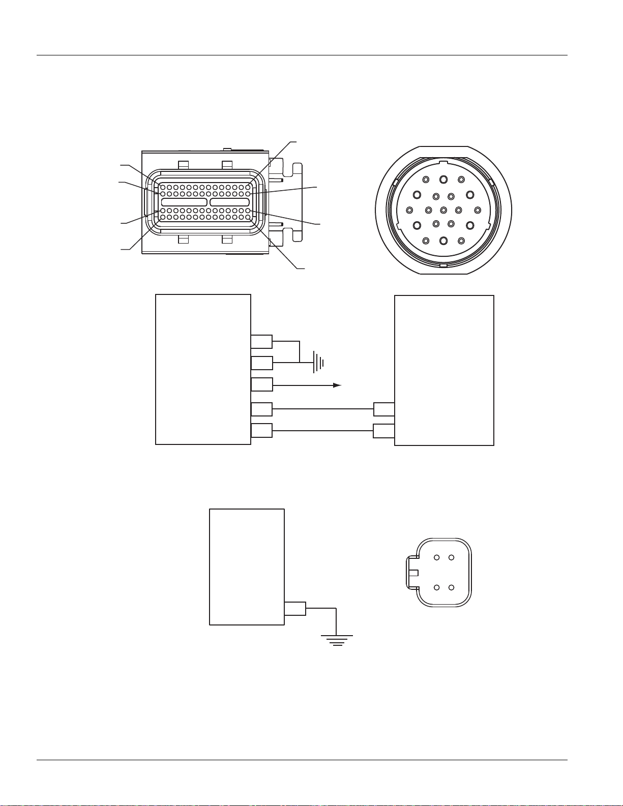
Component Identification
(TECU - Vehicle Interface Connector)
6
12
36
22
38
28
34
Front View
ECA - 3-Way Connector
C
B
1
7
35
13
37
23
29
A
13
(HCM - Vehicle Interface Connector)
29
23
37
35
7
1
ECA -Pack 8-Way Connector
B
A
H
G
C
F
Front View
34
28
38
22
36
12
6
D
E
NOTE: Refer to the Eaton Hybrid Component and Connector Location page for Connector Locations
TECU
Battery
TECU Power
TECU Ground
TECU Ignition
HCM
HCM Ignition (Vehicle)
HCM Ground (Vehicle)
HCM Power (Vehicle)
Clutch Ignition (System)
38
36
35
Neg (-)
Plus (+)
Ignition Relay
87
ECA
35
36
38
13
C
B
H
ECA Power
ECA Ground
26
© 2015 Eaton. All rights reserved
2015.10.19
Page 33

TRTS1000 Electrical Pretest Procedures | Electrical Pretest
Electrical Pretest
Purpose: Verify chassis battery voltage.
A
1. Key off.
2. Inspect starter/battery and Inline fuse holder
connections on Electronic Clutch Actuator (ECA),
Hybrid Control Module (HCM) and Transmission
Electronic Control Unit (TECU) for integrity.
Note: ECA, HCM and TECU use a 30-amp fuse.
Refer to OEM for locations.
3. Measure voltage across batteries.
• If voltage is 11–13 volts on a 12-volt system,
proceed with battery load test. Repair or
replace batteries as required. Go to Step
• If voltage is outside of range, repair or replace
batteries and charging system as required.
Repeat this step.
Connection Measurement
Starter Battery to ECA
Starter Battery to HCM
Starter Battery to TECU
B.
Purpose: Verify ECA battery voltage and ignition
B
status.
1. Key on.
2. Connect ServiceRanger to 9-Way Diagnostic
Connector in the cab.
3. Select the “Data Monitor” option and view the
following parameters under the hybrid (clutch
actuator) list:
- PID 132 “Clutch Actuator Battery Voltage.”
- PID 160 “Clutch Actuator Ignition Switch Status.”
Note: If the clutch parameters can not be viewed on
ServiceRanger, check the power supply to the
ECA with a voltmeter.
• If PID 132 is within 0.6 volts of battery voltage
and PID 160 reads "1", go to Step
• If either voltage is out of range, repair main
power or ignition supply to the ECA. Repeat
this step.
Parameter Reading
PID 132 “Clutch Actuator
Battery Voltage”
C.
PID 160 “Clutch Actuator
Ignition Switch Status”
2015.10.19
© 2015 Eaton. All rights reserved
27
Page 34

Electrical Pretest | Electrical Pretest Procedures TRTS1000
Purpose: Verify HCM battery voltage and ignition
C
status.
1. Select the “Data Monitor” option and view the
following parameters under the HCM list:
- PID 165 “Battery Potential Voltage.”
- PID 166 “Ignition Switch Status.”
Note: If the “Battery Potential Voltage” or “Ignition
Switch Status” can not be viewed on
ServiceRanger, check the power supply to
the HCM with a voltmeter.
• If PID 165 is within 0.6 volts of battery voltage
and PID 166 reads "1", go to Step
• If either voltage is out of range, repair the main
power or ignition supply to the HCM. Repeat
this step.
Parameter Reading
PID 165 “Battery Potential
Voltage”
PID 166 “Ignition Switch
Status”
D.
Purpose: Verify TECU battery and switched
D
voltage.
1. Select the “Data Monitor” option and view the
following parameters under the hybrid
(Transmission) list:
- PID 168 “Battery Potential Voltage.”
- PID 158 “Battery Potential Voltage Switched.”
Note: If the “Battery Potential Voltage” or “Battery
Potential Voltage Switched” can not be
viewed on ServiceRanger, check the power
supply to the TECU with a voltmeter.
• If PID 168 is within 0.6 volts of battery voltage
and PID 158 is within 0.6 volts of ignition
voltage, test is complete. Return to the fault
or symptom procedure that referenced this
step.
• If either voltage is out of range, repair main
power or ignition supply to the TECU. Repeat
this step.
Parameter Reading
PID 168 “Battery Potential
Voltage”
PID 158 “Battery Potential
Voltage Switched”
28
© 2015 Eaton. All rights reserved
2015.10.19
Page 35

TRTS1000 Electrical Pretes t Procedures | Hybrid Electrical Pretest
Hybrid Electrical Pretest
Overview
This test must be performed prior to diagnosing select
hybrid faults. This test verifies the power supply for the
Inverter and Battery Control Unit (BCU).
Note: The Electrical Pretest must be performed before the
Hybrid Electrical Pretest.
Note: This test will be called out in the procedures where it
is required.
Detection
There is no detection process specifically for the basic
electrical supply; however , failures of this type are generally
detected by the hybrid system or driver as some other type
of fault code or symptom.
Fallback
Loss of ignition power causes the hybrid system to be
inoperable. The vehicle runs under diesel power only.
Possible Causes
Low-voltage can be caused by Power Harness connections
from Inverter or BCU.
Additional Tools
• Basic hand tools
• ASTM Class 0 electrical insulating rubber gloves
with leather protectors J48603
• Lockout bracket J48506
• Lockout tags
• Battery load tester
• Eaton® Test Adapter Kit J43318
• Digital Volt/Ohm Meter J46708
• ServiceRanger
2015.10.19
© 2015 Eaton. All rights reserved
29
Page 36
Hybrid Electrical Pretest | Electrical Pretest Procedures TRTS1000
Component Identification
14
28
42
56
Delphi 56-Way Mating Connector View
(Inverter - Low Voltage Connector)
Inverter
Chassis Ground 1
Chassis Ground 2
Inverter Enable
Relay Box Enable
1
2
15
16
Deutsch 19 - Way Mating Connector View
1
15
29
43
(PEC - Low Voltage Connector)
8
7
5
123
4
14
9
10
11
12
13
17
19
18
6
16
15
PEC
HCM
(Pin 2)
6
Ground B
34
7
NOTE: Refer to the Eaton Hybrid Component and Connector Location page for Connector Locations
DC/DC
Converter
4
Ground
DC/DC Converter
4-Way OEM Connector
3
4
1
2
30
© 2015 Eaton. All rights reserved
2015.10.19
Page 37

TRTS1000 Electrical Pretes t Procedures | Hybrid Electrical Pretest
!
Hybrid Electrical Pretest
Purpose: Verify Inverter ground continuity.
A
1. Perform the Electrical Pretest (see “Electrical
Pretest” on page 25.), then continue to step 2.
2. Key off.
Warning: See “High-Voltage Service Shutdown and
Power-Up Procedure” on page 4. Follow the procedures to avoid shock, burn or death from improperly handled high-voltage.
3. Disconnect the Inverter 56-Way Connector.
4. Measure resistance from Pin 1 to battery negative
and then from Pin 2 to battery negative:
• If resistance is 0–0.3 ohms from Pin 1 to
battery negative and from Pin 2 to battery
negative, go to Step
• If resistance is outside of range, repair the
Inverter Ground Harness, then repeat this step.
Connection Measurement
Pin 1 to battery
negative
B.
Purpose: Verify voltage at Inverter 56-Way
B
Connector.
1. Connect a multimeter to the Inverter 56-Way
Connector Pin 15 and Pin 1.
2. Key on.
3. Observe multimeter voltage reading:
• If voltage is 11–13 volts, go to Step
• If voltage is outside of range, repair the
Harness from the HCM, then repeat this step.
Connection Measurement
Pin 15 to Pin 1
Purpose: Verify continuity of Inverter to PEC
C
Ground Wire.
1. Key off.
C.
Pin 2 to battery
negative
2. Reconnect the Inverter 56-Way Connector.
3. Disconnect the PEC 19-Way Connector.
4. Measure resistance from PEC Pin 7 to battery
negative:
• If resistance from Pin 7 to battery negative is
0–0.3 ohms, go to Step
• If resistance is outside of range, repair the
Inverter to PEC Ground Wire, then repeat
this step.
Connection Measurement
Pin 7 to battery
negative
D.
2015.10.19
© 2015 Eaton. All rights reserved
31
Page 38

Hybrid Electrical Pretest | Electrical Pretest Procedures TRTS1000
Purpose: Verify voltage at PEC 19-Way Connector.
D
1. Connect a multimeter to the PEC 19-Way
Connector Pin 6 and Pin 7.
2. Key on.
3. Observe multimeter voltage reading.
• If voltage is 11–13 volts, and vehicle has ePTO
feature on Push Button, go to Step
• If vehicle does not have ePTO feature, test is
complete. Reconnect PEC 19-Way Connector.
See “Fault Code Isolation Procedure Index” on
page 14.
• If voltage is outside of range, repair the Power
Supply Harness from the Inverter, then repeat
this step.
Connection Measurement
6 to 7
E.
Purpose: Verify continuity of DC/DC Ground Wire.
E
1. Key off.
2. Reconnect PEC 19-Way Connector.
3. Disconnect DC/DC Converter 4-Way Connector.
4. Measure resistance from DC/DC Converter 4-Way
Connector Pin 4 to battery negative:
• If resistance between Pin 4 and battery
negative is 0–0.3 ohms, test is complete.
Reconnect the 4-Way Connector. See “Fault
Code Isolation Procedure Index” on page 14.
• If resistance is outside of range, repair the
Ground Harness from the DC/DC Converter to
battery negative, then repeat this step.
Connection Measurement
Pin 4 to battery
negative
32
© 2015 Eaton. All rights reserved
2015.10.19
Page 39

TRTS1000 Fault Isolation Procedures | Fault Code 1 - Motor/Generator Current Sensor
Fault Code 1 - Motor/Generator Current Sensor
J1939: SA 239 SPN 520225 FMI 0, 6
Overview
The High-Voltage Motor/Generator Assembly is connected
to the Inverter Assembly through an AC High-Voltage Cable
that contains 3 separate cables. During operation, the
Inverter monitors the amperage in the AC cables through a
current sensor, which is mounted inside the Inverter. The
inductive sensor produces an output based on amperage
present in the cables.
Detection
The Inverter ignition voltage is greater than 7 volts and less
than 16 volts.
Conditions to Set Fault Code Active
Conditions to Set Fault:
• FMI 6 is set when Inverter detects current input
from the Motor/Generator greater than 100 amps
for 150 MS.
• FMI 0 is set when the Inverter detects current input
from the Motor/Generator greater than 200 amps
for 0.3 MS.
Fallback
When Fault Code 1 is set the following conditions occurs:
• Amber “Check Hybrid” light illuminates.
• Fault is stored in Hybrid Control Module (HCM)
memory.
• Electric Motor/Generator Assist and Regeneration
are disabled; however, the high-voltage relays
remain powered.
• HCM continues to control the hybrid vehicle in a
diesel-only mode.
• Transmission defaults start gear to 1st.
Conditions to Set Fault Code Inactive
Only Inactive faults can be cleared from the Transmission
Electronic Control Unit (TECU) or HCM history using
ServiceRanger. The TECU automatically clears the faults
from history after 200 hours and the HCM automatically
clears the faults from history after the fault has stayed
Inactive for 200 hours.
Possible Causes
This fault code can be caused by any of the following:
• FMI 0, 6
- Inverter
- Motor/Generator
- AC cable
2015.10.19
© 2015 Eaton. All rights reserved
33
Page 40

Fault Code 1 - Motor/Generator Current Sensor | Fault Isolation Procedures TRTS1000
Component Identification
C
ED
High-Voltage AC Harness Connector View
(Amphenol Connector)
A
F
B
F
C
E
A
D
B
High-Voltage AC Motor/Gen Connector View
(Amphenol Connector)
NOTE: Refer to the Eaton Hybrid Component and Connector Location page for Connector Locations
Inverter Motor/
Generator
Phase 3
Phase 2
C
B
Phase 3
C
B
Phase 2
Phase 1
A
A
Phase 1
34
© 2015 Eaton. All rights reserved
2015.10.19
Page 41

TRTS1000 Fault Isolation Procedures | Fault Code 1 - Motor/Generator Current Sensor Test
!
Fault Code 1 - Motor/Generator Current Sensor Test
Purpose: Check for fault code status and continuity
A
of high-voltage circuitry.
1. Review and follow the “Warnings & Cautions” on
page 1.
2. Retrieve Active fault codes and FMIs with ServiceRanger using the 9-Way Diagnostic Connector.
3. Key off.
Danger: See “High-Voltage Service Shutdown and
Power-Up Procedure” on page 4. Follow the procedures to avoid shock, burn or death from improperly handled high-voltage.
4. Remove the AC Cable from the Motor/Generator
and Inverter.
5. Measure resistance of each circuit in the
AC High-Voltage Cable Pins A-A, B-B and C-C:
• If resistance for each circuit is less than
1 ohm, go to Step
• If resistance is outside of range, replace the
AC High-Voltage Cable, then go to Step
B.
V.
Purpose: Verify continuity of high-voltage circuitry
B
to ground.
1. Measure resistance of each circuit to ground in the
AC High-Voltage Cable:
• If resistance between each circuit and ground
is 5M ohms or greater, go to Step
• If resistance is outside of range, replace the
AC High-Voltage Cable, then go to Step
Connection Measurement
Pin A to ground
Pin B to ground
Pin C to ground
C.
V.
Connection Measurement
Pin A to Pin A
Pin B to Pin B
Pin C to Pin C
2015.10.19
© 2015 Eaton. All rights reserved
35
Page 42

Fault Code 1 - Motor/Generator Current Sensor Test | Fault Isolation Pro cedures TRTS1000
Purpose: Verify continuity of high-voltage circuitry.
C
1. Key off.
2. Measure the resistance between the following
AC High-Voltage Cable Pins A-B, B-C and C-A:
• If resistance of each phase is 5M or greater,
go to Step
• If resistance is outside of range, replace the
AC High-Voltage Cable, then go to Step
Connection Measurement
Pin A to Pin B
Pin B to Pin C
Pin C to Pin A
D.
V.
Purpose: Verify continuity of Motor/Generator
D
phases.
1. Measure resistance of each Motor/Generator phase
at the following Pins: A-B, B-C and C-A:
• If resistance of each phase is less than
10 ohms, replace the Inverter
go to Step
• If resistance is outside of range, replace the
Motor/Generator
Connection Measurement
Pin A to Pin B
Pin B to Pin C
Pin C to Pin A
V.
, then go to Step V.
, then
36
© 2015 Eaton. All rights reserved
2015.10.19
Page 43

TRTS1000 Fault Isolation Procedures | Fault Code 1 - Motor/Generator Current Sensor Test
Purpose: Verify repair.
V
1. Key off.
2. Reconnect all connectors and the negative
battery cable.
3. Key on.
4. Clear codes, see “Clear Inactive Faults” on page 13.
5. Drive the vehicle and attempt to reset the code.
6. Check for codes, see “View Active and Inactive
Faults” on page 13.
• If no codes, test is complete.
• If Fault Code 1 appears, find error in testing,
go to Step
• If a code other than 1 appears, see “Fault Code
Isolation Procedure Index” on page 14.
A.
2015.10.19
© 2015 Eaton. All rights reserved
37
Page 44

Fault Code 2 - Motor/Generator Temperature Sensor | Fault Isolation Procedures TRTS1000
Fault Code 2 - Motor/Generator Temperature Sensor
J1939: SA 239 SPN 520226 FMI 3
Overview
The Motor/Generator Temperature Sensor is a thermistor
located inside the Motor/Generator that changes in value
based on the temperature. The Inverter supplies a 5-volt
reference voltage to the sensor and measures the volt drop
in the circuit. When the Motor/Generator temperature is
warm, the sensor resistance is low and the Inverter detects
low-voltage (0.2 volts equals 536 °F [280 °C]). When the
Motor/Generator is cold the sensor resistance is high and
the Inverter detects high voltage (4.1 volts equals or 32 °F
[0 °C]).
Detection
The following preconditions must be met before the system
detects the fault:
• Inverter ignition voltage is greater than 7 volts and
less than 16 volts.
Conditions to Set Fault Code Active
The following conditions must be met to set the fault code
Active:
• FMI 3 is set when the sensor voltage is greater than
4.1 volts for 10 seconds, while the Inverter
temperature is over 35 °C or 95 °F, or if the sensor
output voltage is less than 0.2 volts for 10 seconds.
Fallback
When Fault Code 2 is set the following conditions occur:
• Amber “Check Hybrid” light illuminates.
• Fault is stored in Hybrid Control Module
(HCM) memory.
• High-Voltage Motor/Generator Assist is available,
but at a reduced amount.
Conditions to Set Fault Code Inactive
Only Inactive faults can be cleared from the Transmission
Electronic Control Unit (TECU) or HCM history using
ServiceRanger. The TECU automatically clears the faults
from history after 200 hours and the HCM automatically
clears the faults from history after the fault has been
Inactive for 200 hours.
Possible Causes
This fault code can be caused by any of the following:
•FMI 3
- Motor/Generator
- Short/open Temperature Sensor wires between
the Motor/Generator and the Inverter
- Inverter
Additional Tools
• Basic hand tools
• ASTM Class 0 electrical insulating rubber gloves
with leather protectors J48603
• Lockout bracket J48506
• Lockout tags
• Eaton® Test Adapter Kit J43318
• Digital Volt/Ohm Meter J46708
• ServiceRanger
38
© 2015 Eaton. All rights reserved
2015.10.19
Page 45

TRTS1000 Fault Isolation Procedures | Fault Code 2 - Motor/Generator Temperature Sensor
Component Identification
Delphi 56-Way Mating Connector View
1
Temperature Sensor
14
28
42
15
29
(Harness View - Front Side)
21
56
43
NOTE: Refer to the Eaton Hybrid Component and Connector Location page for Connector Locations
Inverter
TM Ground
38
Motor/Generator
Temperature Sensor
2
Temp Sensor
TM
50
1
Temp Sensor
2015.10.19
© 2015 Eaton. All rights reserved
39
Page 46
Fault Code 2 - Motor/Generator Temperature Sensor Test | Fault Isolation Procedures TRTS1000
!
Fault Code 2 - Motor/Generator Temperature Sensor Test
Purpose: Check for fault code status and continuity
A
of Motor/Generator Temperature Sensor circuit
1. Review and follow the “Warnings & Cautions” on
page 1.
2. Retrieve Active fault codes and FMIs with ServiceRanger using the 9-Way Diagnostic Connector.
3. Key off.
4. Disconnect the Temperature Sensor Connector at
the Motor/Generator.
Warning: See “High-Voltage Service Shutdown and
Power-Up Procedure” on page 4. Follow
the procedures to avoid shock, burn or
death from improperly handled
high-voltage.
5. Measure resistance at the Motor/Generator 2-Way
T emperature Sensor Connector from Pin A to Pin B:
• If resistance is 0.8K ohms to 301.7K ohms,
go to Step
• If resistance is outside of range, replace the
Motor/Generator
B.
, then go to Step V.
Purpose: Verify continuity of Inverter and
B
Motor/Generator Temperature Sensor circuit.
1. Key off.
2. Disconnect the Inverter 56-Way Connector.
3. Reconnect the Motor/Generator 2-Way
Temperature Sensor Connector.
4. Measure resistance at the following:
- Inverter 56-Way Connector Pin 50 to Pin 38
- Inverter 56-Way Connector Pin 50 to ground
Note: Gently flex the Inverter 56-Way Harness
near the Connector while monitoring the
resistance values.
• If resistance is 0.8K–301.7K ohms between
Pin 50 and Pin 38 and resistance between
Pin 50 and ground is 10K ohms or greater,
replace the Inverter
• If resistance is outside of range, repair the
open or short to ground in the harness
between the Inverter 56-Way Connector and
the Motor/Generator 2-Way Connector, then
go to Step
V.
, then go to Step V.
Connection Measurement
Pin A to Pin B
Connection Measurement
Pin 50 to Pin 38
Pin 50 to ground
40
© 2015 Eaton. All rights reserved
2015.10.19
Page 47

TRTS1000 Fault Isolation Procedures | Fault Code 2 - Motor/Generator Te mperature Sensor Test
Purpose: Verify repair.
V
1. Key off.
2. Key on.
3. Reconnect all connectors and the negative
battery cable.
4. Clear codes, see “Fault Code Retrieval and
Clearing” on page 13.
5. Drive vehicle and attempt to reset the code.
6. Check for codes, see “View Active and Inactive
Faults” on page 13.
• If no codes, test is complete.
• If Fault Code 2 appears, find error in testing,
go to Step
A.
• If a code other than 2 appears, see “Fault Code
Isolation Procedure Index” on page 14.
2015.10.19
© 2015 Eaton. All rights reserved
41
Page 48

Fault Code 3 - Motor/Generator Temperature | Fault Isolation Procedures TRTS1000
Fault Code 3 - Motor/Generator Temperature
J1939: SA 239 SPN 520227 FMI 0
Overview
The Motor/Generator temperature is measured through a
thermistor sensor, which is located internal to the unit. The
sensor changes value based on the temperature. The
Inverter supplies a 5-volt reference voltage to the sensor
and measures the volt drop in the circuit.
When the Motor/Generator temperature is warm the sensor
resistance is low and the Inverter detects a low-voltage (0.2
volts equals 536 °F [280 °C]). When the Motor/Generator is
cold, the sensor resistance is high and the Inverter detects
a high voltage (4.1 volts equals 32 °F [0 °C]).
Detection
Inverter ignition voltage is greater than 7 volts and less than
16 volts.
Conditions to Set Fault Code Active
When the Motor/Generator temperature is warm the sensor
resistance is low and the Inverter detects a low-voltage (0.2
volts equals 536 °F [280 °C]). When the Motor/Generator is
cold the sensor resistance is high and the Inverter detects a
high-voltage (4.1 volts equals 32 °F [0 °C ]).
Fallback
When Fault Code 3 is set the following conditions occur:
• Amber “Check Hybrid” light illuminates.
• Fault is stored in Hybrid Control Module (HCM)
memory.
• Electric Motor/Generator Assist and Regeneration
are disabled; however, high-voltage relays remain
powered.
• HCM continues to control the hybrid vehicle in a
diesel-only mode.
• Transmission defaults start gear to 1st.
Conditions to Set Fault Code Inactive
Only Inactive faults can be cleared from the Transmission
Electronic Control Unit (TECU) or HCM history using
ServiceRanger. The TECU automatically clears the faults
from history after 200 hours and the HCM automatically
clears the faults from history after they have been Inactive
for 200 hours.
Possible Causes
This fault code can be caused by any of the following:
• FMI 0 (FMI 0 is set when the temperature sensor
value is greater than 365 °F [185 °C] for 1 second):
- Motor/Generator
- Inverter
- Liquid cooling system (low coolant, no coolant
flow, Coolant Pump, Radiator, Radiator Fan,
reservoir)
Additional Tools
• Basic hand tools
• ASTM Class 0 electrical insulating rubber gloves
with leather protectors J48603
• Lockout bracket J48506
• Lockout tags
• Eaton® Test Adapter Kit J43318
• Digital Volt/Ohm Meter J46708
• ServiceRanger
42
© 2015 Eaton. All rights reserved
2015.10.19
Page 49

TRTS1000 Fault Isolation Procedures | Fault Code 3 - Motor/Generator Temperature
Component Identification
Delphi 56-Way Mating Connector View
1
Temperature Sensor
14
28
42
15
29
(Harness View - Front Side)
21
56
43
NOTE: Refer to the Eaton Hybrid Component and Connector Location page for Connector Locations
Inverter
TM Ground
38
Motor/Generator
Temperature Sensor
2
Temp Sensor
TM
50
1
Temp Sensor
2015.10.19
© 2015 Eaton. All rights reserved
43
Page 50

Fault Code 3 - Motor/Generator Temperature Test | Fault Isolation Procedures TRTS1000
!
Fault Code 3 - Motor/Generator Temperature Test
Purpose: Check for Active or Inactive fault code
A
status.
1. Review and follow the “Warnings & Cautions” on
page 1.
2. Retrieve Active fault codes and FMIs with ServiceRanger using the 9-Way Diagnostic Connector.
Warning: See “High-Voltage Service Shutdown and
Power-Up Procedure” on page 4. Follow the procedures to avoid shock, burn or death from improperly handled high-voltage.
3. Key on.
4. Find initial temperature by selecting the “Data
Monitor” option and view PID 113
“Motor/Generator Temperature” in the “Power
Electronics” list.
5. View PID 113 again after 20 minutes:
• If PID 113 “Motor/Generator Temperature”
dropped from the first reading, go to Step
• If PID 113 “Motor/Generator Temperature”
remained the same, go to Step
H.
B.
Purpose: Verify level of hybrid system coolant.
B
1. Key off.
2. Observe the coolant level after the system has
cooled down to ensure if is filled to the proper level:
• If coolant is within the recommended limits,
go to Step
• If coolant is below the recommended limits,
refer to the OEM for coolant type and fill
procedures. Check for source of coolant leak.
When refilling the system it should be
pressurized or vacuum bleed of air to
ensure the coolant flows properly during
normal operation.
Purpose: Verify integrity of hybrid cooling system
C
components.
C.
Time Temperature
Initial check
20 minute
1. Key off.
2. Visually inspect the hybrid liquid cooling system
radiator for debris, obstruction to airflow, or sharp
bends in the coolant lines:
• If the radiator is free of debris and the coolant
lines are not bent sharply, go to Step
• If the radiator has debris, the air flow is
obstructed, or the coolant lines are bent
sharply, repair the concern, then go to Step
D.
V.
44
© 2015 Eaton. All rights reserved
2015.10.19
Page 51

TRTS1000 Fault Isolation Procedures | Fault Code 3 - Motor/Generator Temperature Test
Purpose: Verify operation of hybrid Coolant Pump.
D
1. Key on.
2. Connect ServiceRanger to the 9-Way Connector in
the cab.
3. Select the Advanced Product Functions option and
select the “Cooling Pump” option.
4. Enable the “Cooling Pump” option:
• If the Coolant Pump turns on, go to Step
• If the Coolant Pump does not turn on,
go to Step
Purpose: Verify operation of hybrid Heat
E
Exchanger Fan.
F.
E.
Purpose: Verify voltage at hybrid Coolant Pump.
F
1. Key on.
2. Disconnect the Coolant Pump 2-Way Connector.
3. Select the “Advanced Products Function” option
and select “Cooling Pump.”
4. Enable the Cooling Pump option.
5. Measure voltage at the 2-Way Connector from
Pin A to Pin B:
• If voltage between Pin A and Pin B is ±0.2 volts
of battery voltage, refer to OEM for Coolant
Pump concern.
• If voltage between Pin A and Pin B is outside
of range, refer to OEM for repair procedures
on Cooling Pump Power Harness or
damaged fuse.
Connection Measurement
1. Select the Advanced Product Functions option and
select the “Heat Exchanger Fan” option.
2. Enable the Heat Exchanger Fan option:
• If the Heat Exchanger Fan turns on, the system
needs to be purged of air, allowing the coolant
to flow. Bleed the air by using a coolant system
pressurizing tool or a vacuum tool, then
go to Step
• If the Heat Exchanger Fan does not turn on,
go to Step
V.
G.
Pin A to Pin B
2015.10.19
© 2015 Eaton. All rights reserved
45
Page 52

Fault Code 3 - Motor/Generator Temperature Test | Fault Isolation Procedures TRTS1000
Purpose: Verify voltage at hybrid Heat Exchanger
G
Fan.
1. Key on.
2. Disconnect the Heat Exchanger Fan
2-way connector.
3. Select the “Advanced Products Function” option
and select the “Heat Exchanger Fan.”
4. Enable the Heat Exchanger Fan option.
5. Measure voltage at the 2-Way Connector from
Pin A to Pin B:
• If voltage between Pin A and Pin B is ±0.2 volts
of battery voltage, refer to OEM for Heat
Exchanger Fan concern.
• If voltage between Pin A and Pin B is outside of
range, refer to OEM for repair procedures on
Heat Exchanger Fan Power Harness or
damaged fuse.
Connection Measurement
Purpose: Verify continuity of Inverter circuitry.
H
1. Key off.
2. Disconnect the Inverter 56-Way Connector.
3. Measure resistance between Pin 38 and Pin 50, and
Pin 50 to ground of the Inverter 56-Way Connector.
• If resistance is 0.8K–301.7K ohms between
Pin 50 and Pin 38 and resistance between
Pin 50 and ground is 10K ohms or greater,
replace the Inverter
• If resistance is outside the range, go to Step I.
Connection Measurement
Pin 50 to Pin 38
Pin 50 to ground
, then go to Step V.
Pin A to Pin B
46
© 2015 Eaton. All rights reserved
2015.10.19
Page 53

TRTS1000 Fault Isolation Procedures | Fault Code 3 - Motor/Generator Temperature Test
Purpose: Verify continuity of Temperature Sensor
I
circuit.
1. Key off.
2. Disconnect the Motor/Generator Temperature
Sensor 2-Way Connector located on the right side
of the Motor/Generator.
3. Measure resistance between the 2-Way
T emperature Sensor Connector from Pin A to Pin B:
• If resistance is 0.8K–301.7K ohms, repair the
shorted HCM System Harness between the
Inverter 56-Way Connector and
Motor/Generator 2-Way Connector.
• If resistance is outside the range, replace the
Motor/Generator
Connection Measurement
Pin A to Pin B
, then go to Step V.
Purpose: Verify repair.
V
1. Key off.
2. Reconnect all connectors and negative
battery cable.
3. Key on.
4. Clear codes, see “Clear Inactive Faults” on page 13.
5. Drive the vehicle and attempt to reset the code.
6. Check for codes, see “View Active and Inactive
Faults” on page 13.
• If no codes, test is complete.
• If Fault Code 3 appears, find error in testing,
go to Step
• If a code other than 3 appears, see “Fault Code
Isolation Procedure Index” on page 14.
A.
2015.10.19
© 2015 Eaton. All rights reserved
47
Page 54

Fault Code 4 - Motor/Generator Rotation Speed Sensor | Fault Isolation Procedures TRTS1000
Fault Code 4 - Motor/Generator Rotation Speed Sensor
J1939: SA 239 SPN 520228 FMI 0, 2, 22–27
Overview
The Motor/Generator Rotation Speed Sensor is mounted to
the back of the Motor/Generator around the Input Shaft.
The sensor (two-piece design) is a rotor mounted to the
Input Shaft and a Sensing Ring mounted to the motor
housing. The Sensing Ring is supplied with low-voltage
during operation. The rotor turns inducing a voltage
fluctuation into the Sensing Ring, which is then converted
into a digital signal for Motor/Generator RPM. Voltage
output and frequency is low at idle and increases with RPM.
Detection
Fault is detected when:
• Inverter ignition voltage is greater than 7 volts and
less than 16 volts.
• FMI 2 does not set if there is an Active
Transmission Input Shaft Speed Sensor fault.
Conditions to Set Fault Code Active
The following conditions must be met to set the fault
code Active:
• FMI 0 is set when the Motor/Generator speed
exceeds the normal allowable range.
• FMI 2 is set when the Motor/Generator speed is
different than Transmission Input Shaft Speed by
more than 100 RPM for at least 10 seconds.
• FMI 22, 24, 25 are set when the combination of
analog-to-digital converter signals are a mismatch.
• FMI 27 is set when the Inverter detects an error
during the initial check.
• FMI 23 is set when there is an analog-to-digital
converter output error signal for 100 MS.
• FMI 26 is set when the rotation sensor speed is
greater than 6000 min-1 for 10 MS.
Fallback
When Fault Code 4 is set the following conditions occur:
• Amber “Check Hybrid” light illuminates.
• Fault is stored in Hybrid Control Module
(HCM) memory.
• Electric Motor/Generator Assist and Regeneration
are disabled; however, the high-voltage relays
remain powered.
• HCM continues to control the hybrid vehicle in a
diesel-only mode.
• Transmission defaults start gear to 1st.
Conditions to Set Fault Code Inactive
Only Inactive faults can be cleared from the Transmission
Electronic Control Unit (TECU) or HCM history using
ServiceRanger. The TECU automatically clears the faults
from history after 200 hours. The HCM automatically clears
the faults from history after the fault has been Inactive for
200 hours.
Possible Causes
This fault code can be caused by any of the following:
•FMI 0
- Long extended grades may require intermittent
use of the service brakes to slow the vehicle
• FMI 22, 24, 25, 27
- Inverter
• FMI 2, 23, 26
- Inverter
- Motor/generator
- Resolver Harness between the Motor/Generator
and Inverter
48
Additional Tools
© 2015 Eaton. All rights reserved
• Basic hand tools
• ASTM Class 0 electrical insulating rubber gloves
with leather protectors J48603
• Lockout bracket J48506
• Lockout tags
• Eaton® Test Adapter Kit J43318
• Digital Volt/Ohm Meter J46708
• ServiceRanger
2015.10.19
Page 55

TRTS1000 Fault Isolation Procedures | Fault Code 4 - Motor/Generator Rotation Speed Sensor
54
51
3
4
Inverter
Motor/Generator
Resolver
14
28
42
56
1
15
29
43
Delphi 56-Way Mating Connector View
REZ S1
REZ S4
53
52
1
2
55
56
5
6
REZ Plus (+)
REZ Minus (-)
REZ S2
REZ S3
Resolver
Resolver
Resolver
Resolver
Resolver
Resolver
Resolver Harness View
(Front Side)
NOTE: Refer to the Eaton Hybrid Component and Connector Location page for Connector Locations
6
4
2
5
3
1
Component Identification
2015.10.19
© 2015 Eaton. All rights reserved
49
Page 56

Fault Code 4 - Motor/Generator Rotation Speed Sensor Test | Fault Isolation Procedures TRTS1000
!
Fault Code 4 - Motor/Generator Rotation Speed Sensor Test
Purpose: Check for Active or Inactive fault code
A
status.
1. Review and follow the “Warnings & Cautions” on
page 1.
2. Retrieve Active fault codes and FMIs with ServiceRanger using the 9-Way Diagnostic Connector.
3. Key off.
Warning: See “High-Voltage Service Shutdown and
Power-Up Procedure” on page 4. Follow the procedures to avoid shock, burn or death from improperly handled high-voltage.
4. Which FMIs are present?
• If FMI 22, 24, 25, or 27 are listed, replace
the Inverter
• If FMI 2, 23, or 26 are listed, go to Step B.
• If FMI 0 is listed, Using ServiceRanger select
the Advanced Product Functions and
download the TECU and HCM snapshots then
contact Eaton® at 1-800-826-HELP (4357).
, then go to Step V.
Purpose: Verify continuity of Resolver and Inverter
B
components.
1. Disconnect the 56-Way Low-Voltage Connector
at the Inverter.
2. Measure Resolver resistance at the 56-Way
Harness Connector between the following pins:
- Pin 55 to Pin 56
- Pin 53 to Pin 54
- Pin 51 to Pin 52
Note: Gently flex the Inverter 56-Way Connector
Harness near the Connector while monitoring
the resistance values.
Resistance ranges for the pins are:
- Pins 55 to Pin 56: 10.5–8.6 ohms
- Pins 53 to Pin 54: 34–28 ohms
- Pins 51 to Pin 52: 27–23 ohms
• If the above resistances are found, and
FMI 2 is Active, contact Eaton at
1-800-826-HELP (4357).
• If the above resistances are found, and
FMI 26 or 23 are Active, replace the Inverter
then go to Step
V.
,
• If resistance is outside of range for any of the
readings, go to Step
Connection Measurement
Pin 55 to Pin 56
Pin 53 to Pin 54
Pin 51 to Pin 52
C.
50
© 2015 Eaton. All rights reserved
2015.10.19
Page 57

TRTS1000 Fault Isolation Procedures | Fault Code 4 - Motor/Generator Rotation Speed Sensor Test
Purpose: Verify continuity of Resolver Harness
C
circuitry.
1. Disconnect the 6-Way Motor/Generator
Resolver Connector.
2. Measure the Resolver resistance at the 6-Way
Harness Connector between the following pins:
- Pin 5 to Pin 6
- Pin 1 to Pin 3
- Pin 2 to Pin 4
Note: An auto-ranging digital Volt/Ohm Meter must
be used.
Resistance ranges for the pins are:
- Pins 5 to Pin 6: 10.5–8.6 ohms
- Pins 1 to Pin 3: 34–28 ohms
- Pins 2 to Pin 4: 27–23 ohms
• If the above resistances are found, repair the
open harness between the Inverter 56-Way
Connector and the Motor/Generator 6-Way
Resolver Connector, then go to Step
• If resistance is outside of range, replace the
Motor/Generator
, then go to Step V.
Purpose: Verify repair.
V
1. Key off.
2. Reconnect all connectors and the negative
battery cable.
3. Key on.
4. Clear codes, see “Clear Inactive Faults” on page 13.
5. Drive the vehicle and attempt to recreate the code.
6. Check for codes, see “View Active and Inactive
Faults” on page 13.
• If no codes, test is complete.
• If Fault Code 4 appears, contact Eaton at
1-800-826-HELP (4357).
• If a code other than 4 appears, see “Fault Code
Isolation Procedure Index” on page 14.
V.
Connection Measurement
Pin 5 to Pin 6
Pin 1 to Pin 3
Pin 2 to Pin 4
2015.10.19
© 2015 Eaton. All rights reserved
51
Page 58

Fault Code 5 - Motor/Generator AC Cable | Fault Isolation Procedures TRTS1000
Fault Code 5 - Motor/Generator AC Cable
J1939: SA 239 SPN 520229 FMI 22–29
Overview
The Motor/Generator AC Cables are connected from the
Motor/Generator to the Inverter. These cables carry up to
500 volts AC 3 phase when the vehicle is in operation.
Detection
The following preconditions must be met before the system
detects the fault:
• Inverters ignition voltage is greater than 7 volts and
less than 16 volts.
• FMI 25–27 require the Motor/Generator RPM to be
greater than 500 RPM.
• FMI 28 requires the Motor/Generator RPM to be
less than 500 RPM.
• FMI 29 requires the Motor/Generator RPM to be
less than 50 RPM.
Conditions to Set Fault Code Active
The following conditions must be met to set the fault
code Active:
• FMI 22, 23, 24 are set when the 2-phase motor
current is more than 360 amps for 0.9 MS.
• FMI 25, 26, 27 are set when the Inverter detects a
single open wire and motor current is less than 8
amps for 200 MS at speeds greater than or equal to
500 RPM and current command from the Inverter
is greater than 20 amps.
• FMI 28 is set when Motor/Generator current is less
than 8 amps for 200 MS at speed less than 500
RPM and current command is greater than 20
amps.
• FMI 29 is set during initialization. The Inverter
determines if the AC Cable is connected between
the motor and Inverter by sending out 20 amps for
200 MS and checking the feedback.
Fallback
When Fault Code 5 is set the following conditions occur:
• Red “Stop Hybrid” light illuminates.
• Fault is stored in Hybrid Control Module
(HCM) memory.
• Inverter shuts high-voltage system off.
• HCM continues to control the hybrid vehicle in a
diesel-only mode.
• If FMI 28, or 29 is present at power up, the vehicle
does not crank.
Conditions to Set Fault Code Inactive
Only Inactive faults can be cleared from the Transmission
Electronic Control Unit (TECU) or HCM history using
ServiceRanger. The TECU automatically clears the faults
from history after 200 hours. The HCM automatically clears
the faults from history after the fault code has been Inactive
for 200 hours.
Possible Causes
This fault code can be caused by any of the following:
• FMI 22, 23, 24
- Inverter
- Motor/generator
- AC cable
• FMI 25, 26, 27, 28, 29
- Motor/generator
- AC cable
Additional Tools
• Basic hand tools
• ASTM Class 0 electrical insulating rubber gloves
with leather protectors J48603
• Lockout bracket J48506
• Lockout tags
• Eaton® Test Adapter Kit J43318
• Digital Volt/Ohm Meter J46708
• ServiceRanger
52
© 2015 Eaton. All rights reserved
2015.10.19
Page 59

TRTS1000 Fault Isolation Procedures | Fault Code 5 - Motor/Generator AC Cable
Component Identification
C
ED
High-Voltage AC Harness Connector View
(Amphenol Connector)
A
F
B
F
C
E
A
D
B
High-Voltage AC Motor/Gen Connector View
(Amphenol Connector)
NOTE: Refer to the Eaton Hybrid Component and Connector Location page for Connector Locations
Inverter Motor/
Generator
Phase 3
Phase 2
C
B
Phase 3
C
B
Phase 2
Phase 1
A
A
Phase 1
2015.10.19
© 2015 Eaton. All rights reserved
53
Page 60

Fault Code 5 - Motor/Generator AC Cable Test | Fault Isolation Procedures TRTS1000
!
Fault Code 5 - Motor/Generator AC Cable Test
Purpose: Check for Active or Inactive fault code
A
status.
1. Review and follow the “Warnings & Cautions” on
page 1.
2. Retrieve Active fault codes and FMIs with ServiceRanger using the 9-Way Diagnostic Connector.
3. Key off.
Warning: See “High-Voltage Service Shutdown and
Power-Up Procedure” on page 4. Follow
the procedures to avoid shock, burn or
death from improperly handled
high-voltage.
4. Which faults are present?
• If Fault Code 5 FMI 22, 23, or 24 are Active,
go to Step
• If Fault Code 5 FMI 25, 26, 27, 28, or 29 are
Active, go to Step
B.
C.
Purpose: Verify continuity of high-voltage cable.
B
1. Key off.
2. Remove the AC high-voltage cable at the
Motor/Generator and Inverter.
3. Measure the resistance between the following
AC cable pins:
- Pin A to Pin B
- Pin B to Pin C
- Pin C to Pin A
• If resistance between each phase is 5M ohms
or greater, replace the Inverter
Step
V.
• If resistance is outside of range, replace the
AC high-voltage cable, then go to Step
Connection Measurement
Pin A to Pin B
, then go to
V.
Pin B to Pin C
Pin C to Pin A
54
© 2015 Eaton. All rights reserved
2015.10.19
Page 61

TRTS1000 Fault Isolation Procedures | Fault Code 5 - Motor/Generator AC Cable Test
Purpose: Verify continuity of high-voltage cable.
C
1. Disconnect the AC high-voltage cable from the
Inverter and Motor/Generator.
2. Measure the resistance of the AC High-Voltage
Cable from the Inverter Connector to the
Motor/Generator Connector on each of the
following pins:
- Pin A to Pin A
- Pin B to Pin B
- Pin C to Pin C
Note: An auto-ranging digital Volt/Ohm Meter must
be used.
• If the resistance of each circuit is 1 ohm or
less, go to Step
• If resistance is outside of range, replace the
AC High-Voltage Cable, then go to Step
Connection Measurement
D.
V.
Purpose: Verify continuity of high-voltage cable.
D
1. Measure the resistance of each Motor/Generator
phase at the following pins:
- Pin A to Pin B
- Pin B to Pin C
- Pin C to Pin A
Note: An auto-ranging digital Volt/Ohm Meter must
be used.
• If the resistance of each phase is 10 ohms or
less, replace the Inverter
• If resistance is outside of range, replace the
Motor/Generator
Connection Measurement
Pin A to Pin B
Pin B to Pin C
, then go to Step V.
, then go to Step V.
Pin A to Pin A
Pin B to Pin B
Pin C to Pin C
Pin C to Pin A
2015.10.19
© 2015 Eaton. All rights reserved
55
Page 62

Fault Code 5 - Motor/Generator AC Cable Test | Fault Isolation Procedures TRTS1000
Purpose: Verify repair.
V
1. Key off.
2. Reconnect all connectors and the negative
battery cable.
3. Key on.
4. Clear codes, see “Clear Inactive Faults” on page 13.
5. Drive the vehicle and attempt to reset the code.
6. Check for codes, see “View Active and Inactive
Faults” on page 13.
• If no codes, test is complete.
• If Fault Code 5 appears, find error in testing,
go to Step
• If a code other than 5 appears, see “Fault Code
Isolation Procedure Index” on page 14.
A.
56
© 2015 Eaton. All rights reserved
2015.10.19
Page 63

TRTS1000 Fault Isolation Procedures | Fault Code 6 - No HCM Operation
Fault Code 6 - No HCM Operation
J1939: SA239 SPN 629 FMI 12, 14
Overview
The Hybrid Control Module (HCM) is mounted to the
transmission and it contains all of the software to control
both the hybrid power electronics as well as the
transmission operation.
Detection
The following preconditions must be met before the system
detects the fault:
• HCM ignition voltage is greater than 7 volts and
less than 16 volts.
Conditions to Set Fault Code Active
The following conditions must be met to set the fault code
Active:
• FMI 12 is set at key on if the HCM detects an
internal failure.
• FMI 14 is set when HCM can not complete write of
EEPROM during shut down.
Fallback
When Fault Code 6 is set the following conditions occur:
• Amber “Check Hybrid” light illuminates if the HCM
sets the fault after power up.
• If the fault occurs at power up the vehicle may
not crank.
Conditions to Set Fault Code Inactive
Only Inactive faults can be cleared from the Transmission
Electronic Control Unit (TECU) or HCM history using
ServiceRanger. The TECU automatically clears the faults
from history after 200 hours. The HCM automatically clears
the faults from history after the fault has been Inactive for
200 hours.
Possible Causes
This fault code can be caused by any of the following:
• FMI 12, 14: HCM
Additional Tools
• Basic hand tools
• ServiceRanger
2015.10.19
© 2015 Eaton. All rights reserved
57
Page 64

Fault Code 6 - No HCM Operation | Fault Isolation Procedures TRTS1000
Component Identification
Note: No Schematic for this code.
Note: For component location refer to the OEM service literature.
58
© 2015 Eaton. All rights reserved
2015.10.19
Page 65

TRTS1000 Fault Isolation Procedures | Fault Code 6 - No HCM Operation T est
Fault Code 6 - No HCM Operation Test
Purpose: Check for Active and Inactive fault code
A
status.
1. Retrieve Active fault codes and FMIs with
ServiceRanger using the 9-Way Diagnostic
Connector:
• If Fault Code 6 is Active, replace the Hybrid
Control Module (HCM).
• If Fault Code 6 is Inactive, test is complete.
2015.10.19
© 2015 Eaton. All rights reserved
59
Page 66

Fault Code 7 - Improper HCM Configuration | Fault Isolation Procedures TRTS1000
Fault Code 7 - Improper HCM Configuration
J1939: SA 239 SPN 629 FMI 13
Overview
The Hybrid Control Module (HCM) is mounted to the
transmission and contains all of the software to control
both the hybrid power electronics as well as the
transmission operation.
Detection
The following preconditions must be met before the system
detects the fault:
• HCM ignition voltage is greater than 7 volts and
less than 16 volts.
Conditions to Set Fault Code Active
The following conditions must be met to set the fault
code Active:
• FMI 13 is set at key on if the HCM data is not read
from memory within 1 second.
Fallback
When Fault Code 7 is set the following conditions occur:
• Amber “Check Hybrid” light illuminates.
• Fault is stored in HCM memory.
• If this fault occurs at power up, the vehicle does not
crank.
Only Inactive faults can be cleared from the Transmission
Electronic Control Unit (TECU) or HCM history using
ServiceRanger. The TECU automatically clears faults from
history after 200 hours. The HCM automatically clears
faults from history after the fault has been Inactive for
200 hours.
Possible Causes
This fault code can be caused by any of the following:
• FMI 13: Improper ECU configuration software
Additional Tools
• Basic hand tools
• ServiceRanger
60
© 2015 Eaton. All rights reserved
2015.10.19
Page 67

TRTS1000 Fault Isolation Procedures | Fault Code 7 - Improper HCM Configuration
Component Identification
Note: No Schematic for this code.
Note: For component location refer OEM service literature.
2015.10.19
© 2015 Eaton. All rights reserved
61
Page 68

Fault Code 7 - Improper HCM Configuration | Fault Isolation Procedures TRTS1000
Fault Code 7 - Improper HCM Configuration
Purpose: Check for Active or Inactive fault code
A
status.
1. Retrieve Active fault codes and FMIs with
ServiceRanger using the 9-Way Diagnostic
Connector.
2. Turn ignition off for 2 seconds.
3. Key on:
• If Fault Code 7 is Active, replace the Hybrid
Control Module (HCM).
• If Fault Code 7 is Inactive, test is complete.
62
© 2015 Eaton. All rights reserved
2015.10.19
Page 69

TRTS1000 Fault Isolation Procedures | Fault Code 8 - Loss of Switched Ignition Power (HCM)
Fault Code 8 - Loss of Switched Ignition Power (HCM)
J1939: SA 239 SPN 158 FMI 4
Overview
The Hybrid Control Module (HCM) is mounted to the
transmission and contains all of the software to control
both the hybrid power electronics as well as the
transmission operation. The HCM ignition power is a fused,
single 12-volt feed that runs through the HCM 38-Way
Vehicle Connector.
Detection
The following preconditions must be met before the system
detects the fault:
• Output Shaft speed must be greater than 0 RPM.
Conditions to Set Fault Code Active
The following conditions must be met to set the fault
code Active:
• FMI 4 is set when the HCM loses ignition power
during operation for 2 seconds or greater.
Note: When troubleshooting an Inactive code refer to the
“Product Diagnostic Mode (PDM)” on page 19.
Fallback
When Fault Code 8 is set the following conditions occurs:
• Amber “Check Hybrid” light illuminates only if the
vehicle is moving.
• Fault is stored in HCM memory.
• Red “Service” light illuminates and an “F” flashes
in the gear display, if the fault occurs prior to
power up.
- Fault is stored in Transmission Electronic
Control Unit (TECU) memory due to lack of
communication with the HCM.
• If fault occurs while the vehicle is moving, the
transmission remains in place and the clutch opens
when the vehicle comes to an idle. The clutch
closes and the vehicle will operate in 1st and
reverse from stop.
• If this fault occurs at power up, the vehicle does
not crank.
Conditions to Set Fault Code Inactive
Only Inactive faults can be cleared from the TECU or HCM
history using ServiceRanger. The TECU automatically clears
the faults from history after 200 hours. The HCM
automatically clears a fault from history after that fault has
been Inactive for 200 hours.
Possible Causes
This fault code can be caused by any of the following:
•FMI 4
- Ignition Power Supply to HCM
-HCM
Additional Tools
• Basic hand tools
• Eaton® Test Adapter Kit J43318
• Digital Volt/Ohm Meter J46708
• ServiceRanger
2015.10.19
© 2015 Eaton. All rights reserved
63
Page 70

Fault Code 8 - Loss of Switched Ignition Power (HCM) | Fault Isolation Procedures TRTS1000
HCM
30
86
87
85
87
86
85
30
35Ignition
Front Harness View
(HCM - Vehicle Interface Connector)
37
38
35
36
1
6
7
12
13
22
23
28
29
34
Typical Relay Switch
Ignition
Relay
Ground
Vehicle
Ignition
12V Truck
Battery
12V Plus
NOTE: Refer to the Eaton Hybrid Component and Connector Location page for Connector Locations
Component Identification
64
© 2015 Eaton. All rights reserved
2015.10.19
Page 71

TRTS1000 Fault Isolation Procedures | Fault Code 8 - Loss of Switched Ignition Power (HCM) Test
Fault Code 8 - Loss of Switched Ignition Power (HCM) Test
Purpose: Check for Active or Inactive fault code
A
status and perform electrical pretest.
1. Review and follow the “Warnings & Cautions” on
page 1.
2. Retrieve Active fault codes and FMIs with ServiceRanger using the 9-Way Diagnostic Connector.
3. Perform the “Electrical Pretest” on page 25:
• If Fault Code 8 is Active after performing the
Electrical Pretest, replace the Hybrid Control
Module (HCM), then go to Step V.
• If Fault Code 8 is Inactive after performing the
Electrical Pretest, go to Step
V.
Purpose: Verify repair.
V
1. Key off.
2. Reconnect all connectors and the negative
battery cable.
3. Key on.
4. Clear codes, see “Clear Inactive Faults” on page 13.
5. Drive the vehicle and attempt to reset the code.
6. Check for codes, see “View Active and Inactive
Faults” on page 13.
• If no codes, test is complete.
• If Fault Code 8 appears, find error in testing,
go to Step
• If a code other than 8 appears, see “Fault Code
Isolation Procedure Index” on page 14.
A.
2015.10.19
© 2015 Eaton. All rights reserved
65
Page 72

Fault Code 9 - Weak Battery Voltage | Fault Isolation Procedures TRTS1000
Fault Code 9 - Weak Battery Voltage
J1939: SA 239 SPN 168 FMI 14
Overview
The Hybrid Control Module (HCM) is mounted to the
transmission and contains all of the software to control
both the hybrid power electronics as well as the
transmission operation. The HCM main battery power is
fused 12-volt feed that runs through the HCM 38-Way
Vehicle Connector with the main ground wire returning to
the battery negative terminal.
Detection
The following preconditions must be met before the system
detects the fault:
• HCM ignition voltage is greater than 7 volts and
less than 16 volts.
• HCM System Battery Voltage Low Fault is Inactive.
Conditions to Set Fault Code Active
The following conditions must be met to set the fault
code Active:
• FMI 14 is set when the HCM battery voltage drops
below 9 volts for 10 seconds.
Note: When troubleshooting an Inactive code refer to the
“Product Diagnostic Mode (PDM)” on page 19.
Conditions to Set Fault Code Inactive
Only Inactive faults can be cleared from the Transmission
Electronic Control Unit (TECU) or HCM history using
ServiceRanger. The TECU automatically clears the faults
from history after 200 hours. The HCM automatically clears
a fault from history after that fault has been Inactive for
200 hours.
Possible Causes
This fault code can be caused by any of the following:
• FMI 14
- Power Supply Harness to the HCM
- Low batteries or bad main power connection
- Charging system
Additional Tools
• Basic hand tools
• Eaton® Test Adapter Kit J43318
• Digital Volt/Ohm Meter J46708
• ServiceRanger
Fallback
When Fault Code 9 is set the following conditions occur:
• Amber “Check Hybrid” light illuminates.
•
Red “Hybrid
additional fault codes caused by the low or weak
voltage. This feature was added with HCM Software
1107 and higher.
• Fault is stored in HCM memory.
Stop” lamp will display if there are
66
© 2015 Eaton. All rights reserved
2015.10.19
Page 73

TRTS1000 Fault Isolation Procedures | Fault Code 9 - Weak Battery Voltage
HCM
30
86
87
85
30
Harness Front View
(HCM - Vehicle Interface Connector)
37
38
35
36
1
6
7
12
13
22
23
28
29
34
Typical Relay Switch
Ignition
Relay
12V Truck
Battery
12V Plus
38
VBATT
NOTE: Refer to the Eaton Hybrid Component and Connector Location page for Connector Locations
36
HCM Ground
Component Identification
2015.10.19
© 2015 Eaton. All rights reserved
67
Page 74

Fault Code 9 - Weak Battery Voltage | Fault Isolation Procedures TRTS1000
Fault Code 9 - Weak Battery Voltage
Purpose: Check for Active or Inactive fault code
A
status and perform Electrical Pretest.
1. Review and follow the “Warnings & Cautions” on
page 1.
2. Retrieve Active fault codes and FMIs with ServiceRanger using the 9-Way Diagnostic Connector.
3. Perform the “Electrical Pretest” on page 25:
• If Fault Code 9 is Active after performing the
Electrical Pretest, replace the Hybrid Control
Module (HCM), then go to Step V.
• If Fault Code 9 is Inactive after performing the
Electrical Pretest, clear codes (see “Clear
Inactive Faults” on page 13.) Go to Step
V.
Purpose: Verify repair.
V
1. Key off.
2. Key on.
3. Clear codes, see “Clear Inactive Faults” on page 13.
4. Reconnect all connectors and the negative
battery cable.
5. Drive the vehicle and attempt to reset the code.
6. Check for codes, see “View Active and Inactive
Faults” on page 13.
• If no codes, test is complete.
• If Fault Code 9 appears, find error in testing,
go to Step
• If a code other than 9 appears, see “Fault Code
Isolation Procedure Index” on page 14.
A.
68
© 2015 Eaton. All rights reserved
2015.10.19
Page 75

TRTS1000 Fault Isolation Procedures | Fault Code 10 - Low Battery Voltage (HCM)
Fault Code 10 - Low Battery Voltage (HCM)
J1939: SA 239 SPN 168 FMI 4
Overview
The Hybrid Control Module (HCM) is mounted to the
transmission and contains the software that controls both
the hybrid power electronics as well as the transmission
operation. The HCM main battery power is a fused, 12-volt
feed and runs through the HCM 38-Way Vehicle Connector
with the main ground wire returning to the battery
negative terminal.
Detection
The following preconditions must be met before the system
detects the fault:
• HCM ignition voltage is greater than 7 volts and
less than 16 volts.
Conditions to Set Fault Code Active
The following conditions must be met to set the fault
code Active:
• FMI 4 is set when the HCM battery voltage drops
below 7 volts for more than 1 second.
Note: When troubleshooting an Inactive code refer to the
“Product Diagnostic Mode (PDM)” on page 19
Conditions to Set Fault Code Inactive
Only Inactive faults can be cleared from the Transmission
Electronic Control Unit (TECU) or HCM history using
ServiceRanger. The TECU automatically clears the fault
from history after 200 hours. The HCM automatically clears
a fault from history after it has been Inactive for 200 hours.
Possible Causes
This fault code can be caused by any of the following:
•FMI 4
- Power Supply Harness to the HCM.
- Low batteries or bad main power connection.
- Charging system.
Additional Tools
• Basic hand tools
• Eaton® Test Adapter Kit J43318
• Digital Volt/Ohm Meter J46708
• ServiceRanger
Fallback
When Fault Code 10 is set the following conditions occur:
• Amber “Check Hybrid” light illuminates.
Red “Hybrid
•
additional fault codes caused by the low or weak
voltage. This feature was added with HCM Software
1107 and higher.
• Fault is stored in HCM memory.
Stop” lamp will display if there are
2015.10.19
© 2015 Eaton. All rights reserved
69
Page 76

Fault Code 10 - Low Battery Voltage (HCM) | Fault Isolation Procedures TRTS1000
HCM
30
86
87
85
30
Harness Front View
(HCM - Vehicle Interface Connector)
37
38
35
36
1
6
7
12
13
22
23
28
29
34
Typical Relay Switch
Ignition
Relay
12V Truck
Battery
12V Plus
38
VBATT
NOTE: Refer to the Eaton Hybrid Component and Connector Location page for Connector Locations
36
HCM Ground
Component Identification
70
© 2015 Eaton. All rights reserved
2015.10.19
Page 77

TRTS1000 Fault Isolation Procedures | Fault Code 10 - Low Battery Voltage (HCM) T est
Fault Code 10 - Low Battery Voltage (HCM) Test
Purpose: Check for Active or Inactive fault code
A
status and perform Electrical Pretest.
1. Review and follow the “Warnings & Cautions” on
page 1.
2. Retrieve Active
viceRanger using the 9-Way Diagnostic Connector.
3. Perform the “Electrical Pretest” on page 25:
• If Fault Code 10 is Active after performi
Electrical Pretest, replace the H
Module (HCM), then go to Step V.
• If Fault Code 10 is Inactive after performing
the Electrical Pretest,
Faults” on page
fault codes and FMIs with Ser-
ng the
ybrid Control
see “Clear
13. Go to Step
Inactive
V.
Purpose: Verify repair.
V
1. Key off.
2. Key on.
3. Clear codes, see “Clear Inactive Faults” on page 13.
4. Reconnect all connectors
y cable.
batter
5. Drive the vehicle and attempt to reset the code.
6. Check for codes, see “View Active and
Faults” on pag
• If no codes, test is complete.
• If Fault Code 10 appears, find error in testing,
go
• If a code other than 10 appears, see “Fault
Code Isolat
to Step
e 13.
A.
ion Procedure Index” on page 14.
and the negative
Inactive
2015.10.19
© 2015 Eaton. All rights reserved
71
Page 78

Fault Code 11 - No TECU Operation | Fault Isolation Procedures TRTS1000
Fault Code 11 - No TECU Operation
J1587:MID 130 SID 254 FMI 12
J1939: SA 3 SPN 629 FMI 12
Overview
The Transmission Electronic Control Unit (TECU) is
mounted to the transmission and contains all of the
software to control the transmission; however, the hybrid
Control Module (HCM) controls the operation of the TECU
during hybrid operation.
Detection
The following preconditions must be met before the system
detects the fault:
• TECU ignition voltage is greater than 7 volts and
less than 16 volts.
Conditions to Set Fault Code Active
The following conditions must be met to set the fault
code Active:
• FMI 12 is set if the TECU detects an intermittent
failure in the Electronic Shifter position.
Fallback
When Fault Code 11 is set the following conditions occur:
• Red “Service” light illuminates and an “F” flashes
in the gear display (only if the fault occurs after
power up).
• Fault is stored in TECU memory.
• If the fault code occurs after power up, the
transmission remains in the current gear and the
clutch opens.
Conditions to Set Fault Code Inactive
Only Inactive faults can be cleared from the TECU or HCM
history using ServiceRanger. The TECU automatically clears
the faults from history after 200 hours. The HCM
automatically clears a fault from history after it has been
Inactive for 200 hours.
Possible Causes
This fault code can be caused by any of the following:
• FMI 12: Electric Shifter
Additional Tools
• Basic hand tools
• ServiceRanger
72
© 2015 Eaton. All rights reserved
2015.10.19
Page 79

TRTS1000 Fault Isolation Procedures | Fault Code 11 - No TECU Operation
Component Identification
Note: No Schematic for this code.
Note: For component location refer to the OEM service literature.
2015.10.19
© 2015 Eaton. All rights reserved
73
Page 80

Fault Code 11 - No TECU Operation Test | Fault Isolation Procedures TRTS1000
Fault Code 11 - No TECU Operation Test
Purpose: Check for Active or Inactive fault code
A
status.
1. Retrieve Active fault codes and FMIs with
ServiceRanger using the 9-Way Diagnostic
Connector:
• If Fault Code 11 is Active, replace the Electric
Shifter.
• If Fault Code 11 is Inactive, test is complete.
74
© 2015 Eaton. All rights reserved
2015.10.19
Page 81

TRTS1000 Fault Isolation Procedures | Fault Code 12 - Improper TECU Configuration
Fault Code 12 - Improper TECU Configuration
J1587: MID130 SID 254 FMI 13
J1939: SA 3 SPN 629 FMI 13
Overview
The Transmission Electronic Control Unit (TECU) is
mounted to the transmission and contains all of the
software to control the transmission operation; however,
the Hybrid Control Module (HCM) controls the operation of
the TECU during hybrid operation.
Detection
The following preconditions must be met before the system
detects the fault:
• TECU is powered and ignition voltage is greater
than 7 volts and less than 16 volts.
Conditions to Set Fault Code Active
The following conditions must be met to set the fault
code Active:
• FMI 13 is set when the TECU is not reading valid
information from memory, including the
transmission table and calibration values within 1
second of power up.
Fallback
When Fault Code 12 is set the following conditions occur:
• Red “Service” light illuminates and “F” flashes in
the gear display.
• If the fault occurs at power up the vehicle does
not crank.
Conditions to Set Fault Code Inactive
Only Inactive faults can be cleared from the TECU or HCM
history using ServiceRanger. The TECU automatically clears
the fault from history after 200 hours. The HCM
automatically clears the fault from history after it has been
Inactive for 200 hours.
Possible Causes
This fault code can be caused by any of the following:
• FMI 13: Improper TECU configuration software
Additional Tools
• Basic hand tools
• ServiceRanger
2015.10.19
© 2015 Eaton. All rights reserved
75
Page 82

Fault Code 12 - Improper TECU Configuration | Fault Isolation Procedures TRTS1000
Component Identification
Note: No Schematic for this code.
Note: For component location refer to the OEM service literature.
76
© 2015 Eaton. All rights reserved
2015.10.19
Page 83

TRTS1000 Fault Isolation Procedures | Fault Code 12 - Improper TECU Configuration Test
Fault Code 12 - Improper TECU Configuration Test
Purpose: Check for Active or Inactive fault code
A
status.
1. Retrieve Active fault codes and FMIs with
ServiceRanger using the 9-Way Diagnostic
Connector:
• If Fault Code 12 is Active, replace the
Transmission Electronic Control Unit (TECU)
• If Fault Code 12 is Inactive, test is complete.
.
2015.10.19
© 2015 Eaton. All rights reserved
77
Page 84

Fault Code 14 - Invalid Shifter Range | Fault Isolation Procedures TRTS1000
Fault Code 14 - Invalid Shifter Range
J1587: MID 130 SID 18, 19 FMI 2, 3, 4
J1939: SA 3 SPN 751 FMI 2, 3, 4
Overview
The Transmission Electronic Control Unit (TECU) is
connected to the shift device, which transmits driver mode
selection data. The only compatible shift devices are the
Eaton® Push Button Shift Control (PBSC) and
OEM-supplied shift lever (if equipped with park). The TECU
checks the vehicle for the type of shift device during the
first power up.
Detection
The following preconditions must be met before the system
detects the fault:
• TECU ignition voltage is greater than 7 volts and
less than 16 volts.
• TECU System Battery Voltage Low Fault is Inactive.
• TECU is being powered up for the first time and no
shift device has been configured.
Conditions to Set Fault Code Active
The following conditions must be met to set the fault
code Active:
• FMI 2 is set when the shifter is not returning a
valid position (PRNDH1)
• FMI 3 is set when the sensor voltage is higher
than expected
• FMI 4 is set when the sensor voltage is lower
than expected
Conditions to Set Fault Code Inactive
Only Inactive faults can be cleared from the TECU or HCM
history using ServiceRanger. The TECU automatically clears
faults from history after 200 hours. The HCM automatically
clears a fault from history after it has been Inactive for
200 hours.
Possible Causes
This fault code can be caused by any of the following:
• FMI 2: Shifter is in between detent positions or
sensor is out of calibration.
• FMI 3: Sensor input is shorted high or sensor
ground in open
• FMI 4: Sensor input is open circuit or shorted
to ground
Additional Tools
• Basic hand tools
• Eaton Test Adapter Kit
• Digital Volt/Ohm Meter
• ServiceRanger
Fallback
When Fault Code 14 is set the following conditions occur:
• “F” appears in the gear display.
• Fault is stored in TECU memory.
• TECU changes to AutoShift control.
• Engine does not crank.
78
© 2015 Eaton. All rights reserved
2015.10.19
Page 85

TRTS1000 Fault Isolation Procedures | Fault Code 14 - Invalid Shifter Range
Harness Front View
(TECU - Vehicle Interface Connector)
37
38
35
36
1
6
12
13
22
23
28
29
34
7
NOTE: Refer to the Eaton Hybrid Component and Connector Location page for Connector Locations
Park Pawl
Actuator
3
1
4
2
Park Pawl Actuator
Park Pawl Actuator
Park Pawl Actuator
Park Pawl Actuator
17
16
15
31
Shift Return (Minus)
Shift Control Input 1
Shift Control (Plus)
Shift Control Input 2
TECU
2
3
4
1
4-way Park Pawl Actuator
Connector
Component Identification
2015.10.19
© 2015 Eaton. All rights reserved
79
Page 86

Fault Code 14 - Invalid Shifter Range Test | Fault Isolation Procedures TRTS1000
Fault Code 14 - Invalid Shifter Range Test
Purpose: Verify supply voltage at Shift Lever.
A
1. Review and follow the “Warnings & Cautions” on
page 1.
2. Disconnect the 4-Way Connector to the
Park Pawl Actuator.
3. Key on.
4. Check for 12-volt supply at 4-Way Connector at
Pin 1 and Pin 2:
• If voltage between Pin 1 and Pin 2 is ±0.2 volts
of battery voltage, go to Step
• If voltage is outside the range, go to Step D.
Connection Measurement
Pin 1 to Pin 2
B.
Purpose: Verify voltage of Shift Lever in neutral po-
B
sition.
1. With the Actuator/Shift Lever in neutral, check
voltage on the following pins:
- Pin 3 to ground
- Pin 4 to ground
• If voltage is between 2.25–2.75,
go to Step
• If voltage is outside the range, replace the Park
Pawl Mechanism Sensor, then go to Step V.
Connection Measurement
Pin 3 to ground
Pin 4 to ground
C.
80
© 2015 Eaton. All rights reserved
2015.10.19
Page 87

TRTS1000 Fault Isolation Procedures | Fault Code 14 - Invalid Shifter Range Test
Purpose: Verify continuity of TECU Harness.
C
1. Disconnect the TECU Vehicle Harness
38-way connector.
2. Check continuity between:
- 38-Way Connector Pin 15 and 4-Way Connector
Pin 4
- 38-Way Connector Pin 16 and 4-Way Connector
Pin 3
• If continuity is complete, replace the
Transmission Electronic Control Unit (TECU)
then go to Step
• If an open is found, repair the Vehicle Harness,
then go to Step
Connection Measurement
Pin 15 to Pin 4
Pin 16 to Pin 3
V.
V.
Purpose: Verify continuity of TECU Harness.
D
1. Disconnect the TECU Vehicle Harness
38-way connector.
2. Check continuity between:
- 38-Way Connector Pin 17 and 4-Way Connector
Pin 1
- 38-Way Connector Pin 31 and 4-Way Connector
Pin 2
• If continuity is complete, replace the
,
Transmission Electronic Control Unit (TECU)
then go to Step
• If an open is found, repair the Vehicle Harness,
then go to Step
Connection Measurement
Pin 17 to Pin 1
Pin 31 to Pin 2
V.
V.
,
2015.10.19
© 2015 Eaton. All rights reserved
81
Page 88

Fault Code 14 - Invalid Shifter Range Test | Fault Isolation Procedures TRTS1000
Purpose: Verify repair.
V
1. Key off.
2. Reconnect all connectors.
3. Key on.
4. Clear Codes, see “Clear Inactive Faults” on page 13.
5. Drive the vehicle and attempt to reset the code.
6. Check for codes, see “View Active and Inactive
Faults” on page 13.
• If no codes, test is complete.
• If Fault Code 14 appears, find error in testing,
go to Step
• If a fault code other than 14 appears, see
“Fault Code Isolation Procedure Index” on
page 14.
A.
82
© 2015 Eaton. All rights reserved
2015.10.19
Page 89

TRTS1000 Fault Isolation Procedures | Fault Code 16 - High Integrity Link (HIL) Test
Fault Code 16 - High Integrity Link (HIL) Test
J1939: SA 3 SPN 625 FMI 2
J1587: MID 130 SID 248 FMI 2
Overview
The High Integrity Link (HIL) is a high-speed twisted pair
500K proprietary data link that connects the Transmission
Electronic Control Unit (TECU) to the Push Button Shift
Control (PBSC). Each module contains an internal 120 ohm
resistor. The HIL carries information such as driver mode
selection and fault information to illuminate the
“Service” light.
Detection
The following preconditions must be met before the system
detects the fault:
• TECU ignition voltage is greater than 7 volts and
less than 16 volts.
• TECU System Battery Voltage Low Fault is Inactive.
• TECU driver interface configuration is set to HIL.
Conditions to Set Fault Code Active
FMI 2 is set when the TECU loses communication for 5
seconds or more with the PBSC.
Note: When troubleshooting an Inactive code refer to the
“Product Diagnostic Mode (PDM)” on page 19.
Conditions to Set Fault Code Inactive
Only Inactive faults can be cleared from the TECU or HCM
history using ServiceRanger. The TECU automatically clears
faults from history after 200 hours. The HCM automatically
clears faults from history after that fault has been Inactive
for 200 hours.
Possible Causes
This fault code can be caused by any of the following:
•FMI 2
- HIL Data Link
-PBSC
-TECU
- Power Supply Harness from TECU to PBSC
Additional Tools
• Basic hand tools
• Eaton® Test Adapter Kit J43318
• Digital Volt/Ohm Meter J46708
• ServiceRanger
Fallback
When Fault Code 16 sets the following conditions occur:
• An “F” appears in the gear display.
• Push Button Mode Light flashes next to the
selected mode and the “Service” light remains off.
• Push Button lights come on and then remains off if
the data link fails at power up.
• Fault is stored in TECU memory.
• Operation mode changes to AutoShift
Fallback mode.
• If the code is Active during power up, transmission
does not engage a gear.
• If the fault is Active while driving, transmission
remains in the current gear. It then shifts into the
default gear once the vehicle stops. Clutch opens at
idle and closes if the throttle is pressed. The vehicle
moves into the default start gear only.
2015.10.19
© 2015 Eaton. All rights reserved
83
Page 90

Fault Code 16 - High Integrity Link (HIL) Test | Fault Isolation Procedures TRTS1000
Harness Front View
TECU - Vehicle Interface Connector
37
38
35
36
1
6
12
13
22
23
28
29
34
7
Harness Front View
Push Button Shift Control Connector
ABCD
E
FG
HJ
K
1
2
3
A1
A3
K1
K3
TECU
PBSC
27
28
F1
F2
HIL Low
HIL High
NOTE: Refer to the Eaton Hybrid Component and Connector Location page for Connector Locations
31
25
J3
C1
Shift Power (-)
Shift Power (+)
HIL Low
HIL High
Shift Power (-)
Shift Power (+)
Component Identification
84
© 2015 Eaton. All rights reserved
2015.10.19
Page 91

TRTS1000 Fault Isolation Procedures | Fault Code 16 - High Integrity Link (HIL) Test
Fault Code 16 - High Integrity Link (HIL) Test
Purpose: Check for Active or Inactive fault code
A
status.
1. Review and follow the “Warnings & Cautions” on
page 1.
2. Retrieve Active fault codes and FMIs with ServiceRanger using the 9-Way Diagnostic Connector.
3. Key on and observe the red Push Button
“Service” light.
• If the red “Service” light turns on,
go to Step
• If the red “Service” light does not turn on,
go to Step
Purpose: Verify voltages at Vehicle Harness.
C.
B.
B
Purpose: Verify voltage at Push Button Shift Con-
C
troller.
1. Key off.
2. Disconnect the 30-Way Push Button Shift
Control Connector.
3. Key on.
4. Connect voltmeter leads to Pin F1 and Pin F2.
Note: Make sure the Volt/Ohm Meter is on the
proper scale (around 10 volts AC).
• If the voltage is 0.10 volts AC or greater,
replace the Shift Control
is Active), then go to Step
• If the voltage is out of range, go to Step F.
Connection Measurement
Pin F1 to Pin F2
(only if fault code
V.
1. Disconnect Shift Control 30-Way Connector.
2. Key on.
3. Measure voltage on 30-Way Connector between
Pin J3 and Pin C1.
• If voltage is within 0.6 volts of battery voltage,
go to Step
• If out of range, go to Step D.
Connection Measurement
Pin J3 to Pin C1
C.
2015.10.19
© 2015 Eaton. All rights reserved
85
Page 92

Fault Code 16 - High Integrity Link (HIL) Test | Fault Isolation Procedures TRTS1000
Purpose: Verify continuity from Vehicle Harness to
D
Push Button Shift Controller.
1. Key off.
2. Disconnect negative battery cable.
3. Disconnect Vehicle Harness 38-Way Connector.
Note: On Peterbilts, disconnect gear display.
4. Measure resistance between:
- Shift Control 30-Way Connector Pin J3 and
Vehicle Harness 38-Way Connector Pin 25.
• If resistance between Pin J3 and Pin 25 is
0–0.3 ohms, go to Step
• If any of the above conditions are not met,
repair the Vehicle Harness between the Shift
Control and TECU, then go to Step
Connection Measurement
Pin J3 to Pin 25
E.
V.
Purpose: Verify continuity from Push Button Shift
E
Controller circuits to ground.
1. Key off.
2. Measure the resistance between:
- Shift Control 30-Way Connector Pin C1
and Vehicle Harness 38-Way Connector Pin 31.
- Shift Control 30-Way Connector Pin C1
and ground.
• If resistance between Pin C1 and Pin 31 is
0–0.3 ohms and resistance between Pin C1
and ground is 10K ohms or greater, replace
Transmission Electronic Control Unit (TECU)
(Only if Fault Code is Active).
• If any of the above conditions are not met,
repair the Vehicle Harness between the TECU
and Shift Control, then go to Step
Connection Measurement
Pin C1 to Pin 31
V.
Pin C1 to ground
86
© 2015 Eaton. All rights reserved
2015.10.19
Page 93
TRTS1000 Fault Isolation Procedures | Fault Code 16 - High Integrity Link (HIL) Test
Purpose: Verify continuity from Push Button Shift
F
Controller circuits to ground.
1. Key off.
2. Disconnect negative battery cable.
3. Disconnect Vehicle Harness 38-Way Connector.
4. Measure resistance between:
- Shift Control 30-Way Connector Pin F1
and Vehicle Harness 38-Way Connector Pin 28.
- Shift Control 30-Way Connector Pin F1
and ground.
• If resistance between Pin F1 and Pin 28 is
0–0.3 ohms and if resistance between Pin F1
and ground is 10K ohms or greater,
go to Step
• If any of the above conditions are not met,
repair the Vehicle Harness between the Shift
Control and TECU, then go to Step
Connection Measurement
G.
V.
Purpose: Verify continuity from Vehicle Harness to
G
Push Button Shift Controller.
1. Key off.
2. Measure resistance between:
- Shift Control 30-Way Connector Pin F2 and
Vehicle Harness 38-Way Connector Pin 27.
- Shift Control 30-Way Connector Pin F2
and ground.
• If resistance between Pin F2 and Pin 27 is
0–0.3 ohms and resistance between Pin F2
and ground is 10K ohms or greater, replace
Transmission Electronic Control Unit (TECU)
(Only if Fault Code is Active). Go to Step
• If any of the above conditions are not met,
repair the Vehicle Harness between the Shift
Control and TECU, then go to Step
Connection Measurement
Pin F2 to Pin 27
V.
V.
Pin F1 to Pin 28
Pin F1 to ground
Pin F2 to ground
2015.10.19
© 2015 Eaton. All rights reserved
87
Page 94

Fault Code 16 - High Integrity Link (HIL) Test | Fault Isolation Procedures TRTS1000
Purpose: Verify repair.
V
1. Key off.
2. Reconnect all connectors and negative
battery cable.
3. Key on.
4. Clear codes, see “Clear Inactive Faults” on page 13.
5. Drive the vehicle and attempt to reset the code.
6. Check for codes see “View Active and Inactive
Faults” on page 13.
• If no codes, test is complete.
• If Fault Code 16 appears, find error in testing,
go to Step
• If a code other than 16 appears, see “Fault
Code Isolation Procedure Index” on page 14.
A.
88
© 2015 Eaton. All rights reserved
2015.10.19
Page 95

TRTS1000 Fault Isolation Procedures | Fault Code 17 - Start Enable Relay
Fault Code 17 - Start Enable Relay
J1939:SA 3 SPN 626 FMI 3, 4
J1587:MID 130 SID 237 FMI 3, 4
Overview
The Start Enable Relay is wired into the Transmission
Electronic Control Unit (TECU) on the coil side of the relay.
At key on, the HCM determines which starting method to
use (high-voltage Motor/Generator or Engine Starter). If the
HCM uses the standard engine Starter , the 12-volt Cranking
Relay is energized supplying battery power to the Start
Enable Relay main feed, which then powers the
Starter Solenoid.
Detection
The following preconditions must be met before the system
detects the fault:
• Transmission Electronic Control Unit (TECU)
ignition voltage is greater than 7 volts and less than
16 volts.
Conditions to Set Fault Code Active
The following conditions must be met to set the fault
code Active:
• FMI 3 is set when the TECU detects an open or
short in the control circuit of the Start Enable Relay
for 1 second or greater.
• FMI 4 is set if the TECU detects a short to ground in
the control circuit of the Start Enable Relay for 1
second or greater .
Conditions to Set Fault Code Inactive
Only Inactive faults can be cleared from the TECU or HCM
history using ServiceRanger. The TECU automatically clears
the faults from history after 200 hours. The HCM
automatically clears a fault from history after it has been
Inactive for 200 hours.
Possible Causes
This fault code can be caused by any of the following:
• FMI 3, 4
- Loose or corroded connections, bent or burnt
pins, short to ground, open, or short to VBATT
on the circuit.
- Start Enable Relay
-TECU
Additional Tools
• Basic hand tools
• Eaton® Test Adapter Kit J43318
• Digital Volt/Ohm Meter J46708
• ServiceRanger
Note: When troubleshooting an Inactive code refer to the
“Product Diagnostic Mode (PDM)” on page 19.
Fallback
When Fault Code 17 is set the following conditions occur:
• Red “Service” light illuminates and an “F” flashes in
the gear display.
• Fault is stored in TECU memory.
• If the fault sets at power up the engine still cranks,
provided the high-voltage batteries have a
sufficient State of Charge (SOC).
• If the fault sets while driving, the vehicle continues
to operate.
2015.10.19
© 2015 Eaton. All rights reserved
89
Page 96

Fault Code 17 - Start Enable Relay | Fault Isolation Procedures TRTS1000
Front Harness View
(TECU - Vehicle Interface Connector)
37
38
35
36
1
6
12
13
22
23
28
29
34
7
TECU
30
86
87
85
4
32
85
86
Start Enable
Relay
Start Enable Minus
Start Enable Plus
Typical Relay Switch
NOTE: Refer to the Eaton Hybrid Component and Connector Location page for Connector Locations
Component Identification
90
© 2015 Eaton. All rights reserved
2015.10.19
Page 97

TRTS1000 Fault Isolation Procedures | Fault Code 17 - Start Enable Relay Test
Fault Code 17 - Start Enable Relay Test
Purpose: Check for Active or Inactive fault code
A
status.
1. Review and follow the “Warnings & Cautions” on
page 1.
2. Retrieve Active fault codes and FMIs with ServiceRanger using the 9-Way Diagnostic Connector.
View FMIs present.
3. Exchange the current Start Enable Relay with
another relay and see if fault returns:
• If fault does not return with new relay, replace
the Start Enable Relay (only if fault code is
Active), then go to Step
• If fault returns with new relay, go to Step B.
Purpose: Verify FMI set.
V.
B
Purpose: Verify continuity of Transmission
C
Harness circuits.
1. Key off.
2. Disconnect negative battery cable.
3. Disconnect the Transmission Harness
38-way connector.
4. Measure resistance between Vehicle Harness
38-Way Connector Pin 32 and Pin 4:
• If resistance between Pin 32 and Pin 4 is
40–120 ohms, go to Step
• If resistance is outside of range, repair the
Vehicle Harness for an open circuit, then
go to Step
Connection Measurement
Pin 32 to Pin 4
V.
D.
1. Which FMIs were listed from Step A?
• If FMI 3 is listed, go to Step
• If FMI 4 is listed, go to Step E.
C.
2015.10.19
© 2015 Eaton. All rights reserved
91
Page 98

Fault Code 17 - Start Enable Relay Test | Fault Isolation Procedu res TRTS1000
Purpose: Verify voltages at Transmission Harness.
D
1. Key on.
2. Measure voltage between Vehicle Harness 38-Way
Connector Pin 32 and ground:
Note: The voltage reads 5 volts for only
1–2 seconds.
• If the voltage between Pin 32 and ground is
5 volts, replace the Transmission Electronic
Control Unit (TECU) (only if fault code is
Active), then go to Step
• If the voltage between Pin 32 and ground is
12 volts, repair the short to VBATT on the
harness. Voltage should remain at 5 volts for
1–2 seconds after initial key on. Go to Step
Connection Measurement
Pin 32 to ground
V.
V.
Purpose: Verify continuity of Transmission
E
Harness circuits to ground.
1. Key off.
2. Disconnect battery cable.
3. Disconnect the Transmission Harness
38-Way Connector.
4. Measure the resistance between Vehicle Harness
38-Way Connector Pin 32 and ground:
• If the resistance between 32 and ground is 10K
ohms or greater, replace the Transmission
Electronic Control Unit (TECU) (only if fault
code is Active), then go to Step
• If the resistance is outside of range, repair the
Vehicle Harness for a short to ground, then
go to Step
Connection Measurement
Pin 32 to ground
V.
V.
92
© 2015 Eaton. All rights reserved
2015.10.19
Page 99

TRTS1000 Fault Isolation Procedures | Fault Code 17 - Start Enable Relay Test
Purpose: Verify repair.
V
1. Key off.
2. Reconnect all connectors and negative
battery cable.
3. Key on.
4. Clear codes, see “Clear Inactive Faults” on page 13.
5. Drive the vehicle and attempt to reset the code.
6. Check for codes, see “View Active and Inactive
Faults” on page 13.
• If no codes, test is complete.
• If Fault Code 17 appears, find error in testing,
go to Step
• If a code other than 17 appears, see “Fault
Code Isolation Procedure Index” on page 14.
A.
2015.10.19
© 2015 Eaton. All rights reserved
93
Page 100

Fault Code 18 - ECA Communication | Fault Isolation Procedures TRTS1000
Fault Code 18 - ECA Communication
J1939: SA 239 SPN 520200 FMI 2, 9
Overview
The Electric Clutch Actuator (ECA) controls the position of
the clutch assembly. The ECA communicates with the
Hybrid Control Module (HCM) over the proprietary
Controller Area Network (CAN) data link to change position,
show faults or transmit other operation information.
Detection
The following preconditions must be met before the system
detects the fault:
• HCM ignition voltage is greater than 7 volts and
less than 16 volts.
• ECA ignition voltage is greater than 8.5 volts.
• HCM CAN data link error is Inactive.
Conditions to Set Fault Code Active
The following conditions must be met to set the fault
code Active:
• FMI 9 is set when the ECA loses communication on
the CAN Data Link for 2 seconds.
Fallback
When Fault Code 18 is set the following conditions occur:
• Red “Stop Hybrid” light illuminates.
• Fault is stored in HCM memory.
• ECA maintains current clutch position or moves to
the last position commanded by the HCM. Upon
approaching idle, the clutch opens and remains in
this state.
• If the fault occurs at power up, the vehicle does
not crank.
Conditions to Set Fault Code Inactive
Only Inactive faults can be cleared from the Transmission
Electronic Control Unit (TECU) or HCM history using
ServiceRanger. The TECU automatically clears faults from
history after 200 hours. The HCM automatically clears a
fault from history after that fault has been Inactive for
200 hours.
Possible Causes
This fault code can be caused by any of the following:
•FMI 9
- CAN Data Link from the ECA to the link
-ECA
-HCM
Additional Tools
• Basic hand tools
• Eaton® Test Adapter Kit J43318
• Digital Volt/Ohm Meter J46708
• ServiceRanger
94
© 2015 Eaton. All rights reserved
2015.10.19
 Loading...