

Page 1

Troubleshooting Manual
Gen II Automated Transmissions
TRTS0062 EN-US
May 2013
FO-6406A-ASW
FO-6406A-ASX
FO-8406A-ASW
FO-8406A-ASX
RT-14910B-A S2
RTLO-14918A-AS2
RTLO -16918A-AS2
RTLO-18918A-AS2
RTLO-20918A-AS2
RTLO -22918A-AS2
RTO-1 071 0B-AS2
RTO-1 091 0B-AS2
RTO-1 091 0B-DM2
RTO-12710B-AS2
RTO-12910B-AS2
RTO-12910B-DM2
RTO-14710B-AS2
RTO-14710C-A S2
RTO-14910B-AS2
RTO-14910B-DM2
RTO-14910C-A S2
RTO -16710C-AS2
RTO -16910B-AS2
RTO -16910B-DM2
RTO -16910C-AS2
RTO-18910B-AS2
Page 2

Page 3

TRTS0062
Table of Contents
Table of Contents
General Information
Warnings and Cautions . . . . . . . . . . . . . . . . . . . . . . . . .1
Suggested Tools . . . . . . . . . . . . . . . . . . . . . . . . . . . . . .2
Air Gauges . . . . . . . . . . . . . . . . . . . . . . . . . . . . . . . .2
Volt/Ohm Meter . . . . . . . . . . . . . . . . . . . . . . . . . . . .2
PC-based Service Tool “ServiceRanger” . . . . . . . . .2
Shift Lever Tester . . . . . . . . . . . . . . . . . . . . . . . . . .2
Eaton Test Adapter Kit . . . . . . . . . . . . . . . . . . . . . . .2
6-Pin Deutsch Diagnostic Adapter . . . . . . . . . . . . . .2
. . . . . . . . . . . . . .3
Transmission Models Included . . . .
Diagnostic Procedure . . . . . . . . . . . . . . . . . . . . . . . . . .4
Fault Code Retrieval/Clearing . . . . . . . . . . . . . . . . . . . .5
Retrieving Fault Codes . . . . . . . . . . . . . . . . . . . . . .5
Clearing Fault Codes . . . . . . . . . . . . . . . . . . . . . . . .6
Driving Techniques . . . . . . . . . . . . . . . . . . . . . . . . . . . .7
Fault Code Isolation Procedure Index . . . . . . . . . . . . .12
Symptom-Driven Diagnostics Index . . . . . . . . . . . . . .14
.
Electrical Pretest Procedure
Electrical System Pretest . . . . . . . . . . . . . . . . . . . . . .15
Power-Up Sequence Pretest . . . . . . . . . . . . . . . . . . . .18
Air Pretest . . . . . . . . . . . . . . . . . . . . . . . . . . . . . . . . . .24
Fault Isolation Procedure
Fault Code 11: Shift Controller . . . . . . . . . . . . . . . . . .28
Fault Code 12: Transmission Controller . . . . . . . . . . .32
Fault Code 14: Invalid Lever Position . . . . . . . . . . . . .36
Fault Code 16: Eaton Proprietary Link (EPL) . . . . . . . .42
Fault Code 17: Start Enable Relay Coil . . . . . . . . . . . .48
Fault Code 26: Clutch Slip . . . . . . . . . . . . . . . . . . . . . .54
Fault Code 27: Clutch Disengagement . . . . . . . . . . . . .58
.
Fault Code 28: Clutch System Fault
Fault Code 31: Momentary Engine Ignition
Interrupt Relay (MEIIR) . . . . . . . . . . . . . . . . . . . . . . . .68
Fault Code 32: Switched System Voltage . . . . . . . . . .74
Fault Code 33: Battery Voltage Supply . . . . . . . . . . . .78
Fault Code 35: J1939 Data Link . . . . . . . . . . . . . . . . .82
Fault Code 41: Range Failed to Engage . . . . . . . . . . . .88
Fault Code 42: Splitter Failed to Engage . . . . . . . . . . .92
Fault Code 43: Range Valve . . . . . . . . . . . . . . . . . . . . .96
Fault Code 44: Inertia Brake Solenoid Coil . . . . . . . .102
Fault Code 46: Splitter Valve . . . . . . . . . . . . . . . . . . .108
Fault Code 51: Rail Select Sensor . . . . . . . . . . . . . . .114
. . . . . . . . . . . . . .62
Fault Code 52: Gear Select Sensor . . . . . . . . . . . . . .120
Fault Code 56: Input Shaft Speed Sensor . . . . . . . . .124
Fault Code 57: Main Shaft Speed Sensor . . . . . . . . .130
Fault Code 58: Output Shaft Speed Sensor . . . . . . . .134
Fault Code 61: Rail Select Motor . . . . . . . . . . . . . . . .140
Fault Code 63: Gear Select Motor . . . . . . . . . . . . . . .146
Fault Code 65: Logic Power . . . . . . . . . . . . . . . . . . .152
Fault Code 71: Stuck Engaged . . . . . . . . . . . . . . . . . .158
Fault Code 72: Failed to Select Rail . . . . . . . . . . . . . .162
Fault Code 73: Failed to Engage Gear . . . . . . . . . . . .166
Fault Code 74: Failed to Synchronize . . . . . . . . . . . .170
Voltage
. . . . . . . .174
. . . . . .186
Fault Code 81: Gear Engagement D
Fault Code 83: Missing Lever . . . . . . . . . . . . . . . . . .178
Fault Code 91: Power Connection . . . . . . . . . . . . . . .182
Fault Code 92: Weak System Battery
Fault Code 93: Loss of J1939 Communication
from the Engine . . . . . . . . . . . . . . . . . . . . . . . . . . . .190
etected
Symptom Isolation Procedure
Electrical System . . . . . . . . . . . . . . . . . . . . . . . . . . . .194
Front Box Control . . . . . . . . . . . . . . . . . . . . . . . . . . .204
Gear Display Power Supply . . . . . . . . . . . . . . . . . . . .208
Start Enable Relay Contact . . . . . . . . . . . . . . . . . . . .214
AutoShift Will Not Engage a Gear . . . . . . . . . . . . . . .220
UltraShift DM Will Not Engage a Gear . . . . . . . . . . . .228
UltraShift ASW Will Not Engage a Gear . . . . . . . . . . .236
J1587 Data Link . . . . . . . . . . . . . . . . . . . . . . . . . . . .242
Range System Test . . . . . . . . . . . . . . . . . . . . . . . . . .248
Splitter System . . . . . . . . . . . . . . . . . . . . . . . . . . . . .252
Up/Down Button Test . . . . . . . . . . . . . . . . . . . . . . . .256
UltraShift DM Shift Complaint . . . . . . . . . . . . . . . . . .260
UltraShift ASW Shift Complaint . . . . . . . . . . . . . . . . .266
UltraShift ASW Clutch Engagement . . . . . . . . . . . . .274
Transmission Air Leak . . . . . . . . . . . . . . . . . . . . . . .278
Shift Lever Back Light . . . . . . . . . . . . . . . . . . . . . . . .284
2013.07.17
© 2013 Eaton. All rights reserved
i
Page 4

T
able of Contents TRTS0062
Appendix
Connector Pin Descriptions . . . . . . . . . . . . . . . . . . .288
Transmission Controller 18-Way
(Vehicle Interface Connector) . . . . . . . . . . . . . . .288
Transmission Controller 30-W
Shift Controller 30-Way Connector . . . . . . . . . . .291
Wiring Diagrams . . . . . . . . . . . . . . . . . . . . . . . . . . . .294
6-Speed and 7-Speed AutoShift . . . . . . . . . . . . .294
6-Speed UltraShift ASW . . . . . . . . . . . . . . . . . . .296
10-Speed AutoShift . . . . . . . . . . . . . . . . . . . . . . .298
10-Speed UltraShift DM . . . . . . . . . . . . . . . . . . .300
18-Speed AutoShift . . . . . . . . . . . . . . . . . . . . . . .302
Eaton Shift Lever . . . . . . . . . . . . . . . . . . . . . . . . .304
OEM Shift Lever . . . . . . . . . . . . . . . . . . . . . . . . .304
Proper Clutch Operation . . . . . . . . . . . . . . . . . . . . . .306
Check For Proper Clutch Operation
Confirm Proper Clutch Adjustment
and Clutch Brake Contact . . . . . . . . . . . . . . . . . .306
Adapter Test Kit J43318 . . . . . . . . . . . . . . . . . . . . . .308
Gray Adapters . . . . . . . . . . . . . . . . . . . . . . . . . . .308
Purple Adapters . . . . . . . . . . . . . . . . . . . . . . . . . .308
Adapter Pins . . . . . . . . . . . . . . . . . . . . . . . . . . . .308
Troubleshooting Worksheet . . . . . . . . . . . . . . . . . . .309
ay Connector . . . .289
. . . . . . . . . . .306
ii
© 2013 Eaton. All rights reserved
2013.07.17
Page 5

TRTS0062 General Information | Warnings and Cautions
!
!
!
Warnings and Cautions
Warning: Follow the specified procedures in the indicated
order to avoid personal injury
Caution: Follow the specified procedures in the indicated
order to avoid equipment malfunction or damage
Note: Additional relevant information not covered in the
service procedure.
Before starting a vehicle:
• Sit in the driver's seat
• Place Shift Lever in neutral
• Set the parking brake
Before working on a vehicle or leaving the cab with engine
running:
• Place Shift Lever in neutral
• Set the parking brake
• Block the wheels
When parking the vehicle or leaving the cab:
• Place Shift Lever in neutral
• Set the parking brake
Caution: Do not release the parking brake or attempt to
select a gear until the air pressure is at the correct level.
To avoid damage to the transmission during towing:
1. Place Shift Lever in neutral
2. Lift the drive wheels off of the ground or disconnect the drivelink
Do not operate vehicle if Alternator light is lit or if gauges
indicate low voltage.
2013.07.17
© 2013 Eaton. All rights reserved
1
Page 6

Suggested Tools | General Information TRTS0062
Suggested Tools
Air Gauges
• 2 (0-100) PSI Air Gauges
Volt/Ohm Meter
• SPX / Kent-Moore 1 (800) 328-6657
• P/N 5505027
PC-based Service Tool “ServiceRanger”
• Contact your OEM
Shift Lever Tester
• Eaton Service Parts 1 (800) 826-4357
• P/N 691795
Eaton Test Adapter Kit
• SPX / Kent-Moore 1 (800) 328-6657
• P/N J-43318
6-Pin Deutsch Diagnostic Adapter
• SPX / Kent-Moore 1 (800) 328-6657
• P/N J-38500-60A
For more information call 1-800-826-HELP (826-4357)
2
© 2013 Eaton. All rights reserved
2013.07.17
Page 7
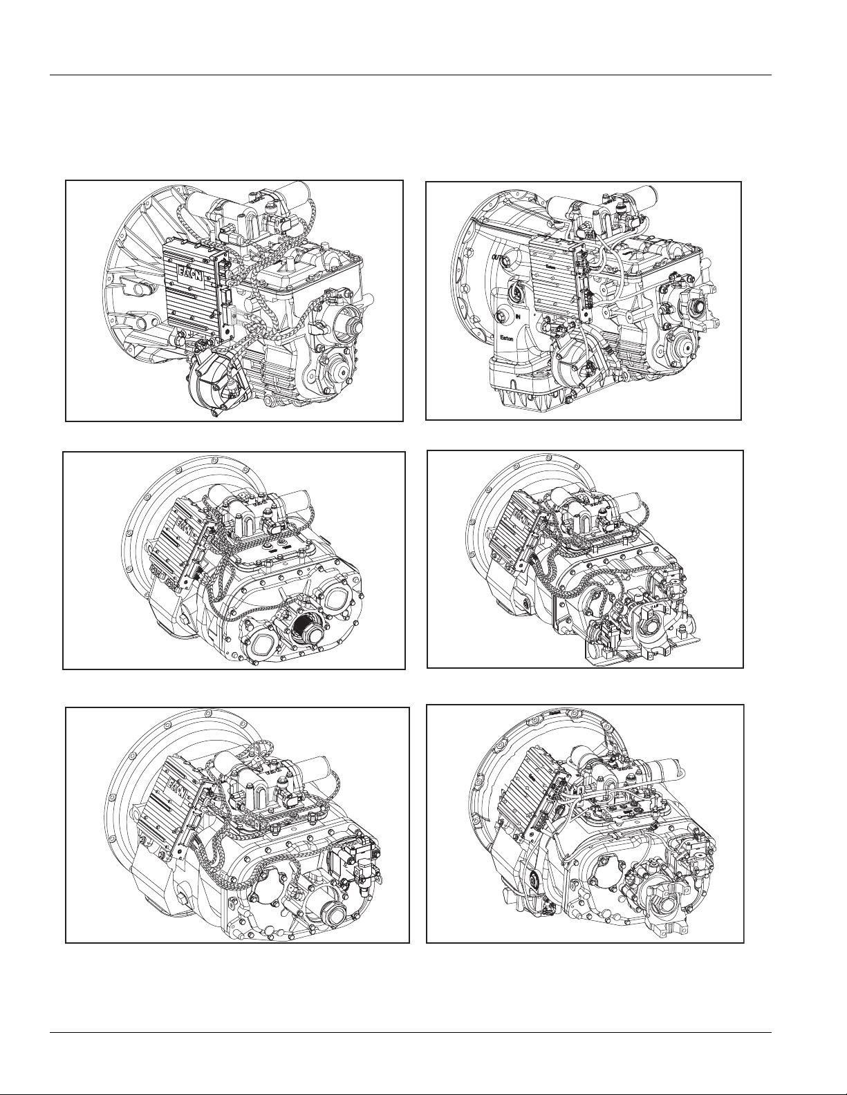
TRTS0062 General Information | Transmission Models Included
Transmission Models Included
6-Speed
7-Speed 18-Speed
6-Speed ASW
10-Speed
2013.07.17
10-Speed DM
© 2013 Eaton. All rights reserved
3
Page 8

Diagnostic Procedure | General Information TRTS0062
Diagnostic Procedure
Follow the flow chart below for all AutoShift failures. Perform tests and procedures as directed by the flowchart.
Key on.
Retrieve active codes. Note: Scan tool
or P.C. may be required if service light
is not avialable.
•Perform Electrical System Pretest
Active codes?
YES
NO
• Refer to the Fault Code Isolation
Procedure Index to select a Fault
Code Isolation Procedure
Observe Gear Display
Can a solid "N"
be observed in
Gear Display ?
YES
Retrieve Inactive Codes.
Inactive Codes?
NO
Symptom?
NO
YES
YES
Will engine crank ?
•Perform Gear Display Test
• Record and clear codes
• Perform Driving Technique to reproduce
the inactive fault code
•Perform Electrical System Pretest
•Perform Air Pretest
• Refer to the Fault Code Isolation
Procedure Index to select
a fault code isolation procedure
•Perform Electrical System Pretest
•Perform Air Pretest
•Perform Power-Up Sequence Test
• Refer to Symptom-Driven Diagnostics
Table to select a symptom isolation procedure
YES
•Perform Power-Up Sequence Test
•Perform Front Box Control Test
NO
NO
Test complete.
4
© 2013 Eaton. All rights reserved
2013.07.17
Page 9

TRTS0062 General Information | Fault Code Retrieval/Clearing
2 times
off
on
4 times
off
on
SERVICE
1 Flash
Short
pause
(1/2 sec)
Short
pause
(1/2 sec)
Long Pause
(3-4 sec)
3 Flashes
2 Flashes
Code 13
Code 21
SERVICE
SERVICE
SERVICE
SERVICE
SERVICE
1 Flash
SERVICE
Fault Code Retrieval/Clearing
Retrieving Fault Codes
Retrieve fault codes by enabling self-diagnostic mode.
Note: Use a PC-based Service Tool, such as the ServiceRanger to retrieve fault codes.
1. Place the Shift Lever in neutral.
2. Set the parking brake.
3. Turn the key on but do not start the engine. If the
engine is running, you may still retrieve codes;
however, do not engage the Starter if the engine
stalls.
4. To Retrieve Active Codes: Turn the key off and on 2
times within 5 seconds ending with the key on.
After 5 seconds, the Service light begins flashing
2-digit fault codes. If no faults are Active, the Service light will flash Code 25 (no codes).
6. Observe the sequence of flashes on the Indicator
light and record the codes. A 1 to 2 second pause
separates each stored code, and the sequence
automatically repeats after all codes have been
flashed.
5. To Retrieve Inactive Codes: Start with the key on.
Turn key off and on 4 times within 5 seconds ending with the key on. After 5 seconds, the Service
light begins flashing 2-digit fault codes. If no faults
are Active, the Service light will flash Code 25 (no
codes).
2013.07.17
© 2013 Eaton. All rights reserved
5
Page 10

Fault Code Retrieval/Clearing | General Information TRTS0062
Clearing Fault Codes
The following procedure clears all Inactive fault codes from
the Transmission Controller memory. Active fault codes will
be automatically cleared when the fault has been corrected.
Note: You may use a PC-based Service Tool, such as ServiceRanger, to clear fault codes.
1. Place the Shift Lever in neutral.
2. Set the parking brake.
3. Turn the key on, but do not start the engine.
4. Start with the key on. Turn the key off and on 6
times within 5 seconds ending with the key on.
6 times
off
on
Note: If the codes have been successfully cleared, the
Service light will come on and stay on for 5 seconds.
5. Turn key off and allow the system to power down.
6
© 2013 Eaton. All rights reserved
2013.07.17
Page 11

TRTS0062 General Information | Driving Techniques
Driving Techniques
Fault
Codes
11 254 12 Shift Controller Component
12 233 12
14 18 2, 4, 5
16 248 2
PID SID FMI Description Type of Code Driving Technique
Transmission
Controller
Invalid lever Position Test
Eaton Proprietary Link (EPL)
Component
Component
Component
Key on. If the fault is present, the system should
automatically detect the problem and set the code.
If the fault is not present at key on, operate the vehicle and attempt to duplicate the driving conditions that triggered the fault code. Possible
triggers include heat and vibration.
Key on. If the fault is present, the system should
automatically detect the problem and set the code.
If the fault is not present at key on, operate the vehicle and attempt to duplicate the driving conditions that triggered the fault code. Possible
triggers include heat and vibration.
Key on. If the fault is present, the system should
automatically detect the problem and set the code.
If the fault is not present at key on, operate the vehicle and attempt to duplicate the driving conditions that triggered the fault code. Possible
triggers include heat and vibration.
Key on. If the fault is present, the system should
automatically detect the problem and set the code.
If the fault is not present at key on, operate the vehicle and attempt to duplicate the driving conditions that triggered the fault code. Possible
triggers include heat and vibration.
17 237 3, 4
25 NO CODES
26 55 10 Clutch Slip Component
2013.07.17
Start Enable Relay Coil
© 2013 Eaton. All rights reserved
Component
Key on. If the fault is present, the system should
automatically detect the problem and set the code.
If the fault is not present at key on, operate the vehicle and attempt to duplicate the driving conditions that triggered the fault code. Possible
triggers include heat and vibration.
Operate the vehicle under load in highest gear
possible with engine speed above 1500 RPM. At a
steady speed, quickly and fully press the throttle.
The failure is detected when clutch slip occurs.
7
Page 12

Driving Techniques | General Information TRTS0062
Fault
Codes
PID SID FMI Description Type of Code Driving Technique
27 55 7
28 52 3,4,5,7
31 218 3,4
Clutch Disengagement
Clutch System
Fault
Momentary Ignition Interrupt Relay
Component
Component
Component
Operate the vehicle. If the fault is present, the system should automatically detect the problem and
set the code. If the fault is not present, operate the
vehicle and attempt to duplicate the driving conditions that triggered the fault code. Possible triggers include heat, vibration and aggressive stops.
Key on. If the fault is present, the system should
automatically detect the problem and set the code.
If the fault is not present at key on, operate the vehicle and attempt to duplicate the driving conditions that triggered the fault code. Possible
triggers include low clutch fluid level, heat and vibration.
Key on. If the fault is present, the system should
automatically detect the problem and set the code.
This fault is only detected during system power-up. If the fault is not present at power up, operate the vehicle and attempt to duplicate the driving
conditions that triggered the fault code. Possible
triggers include heat, vibration.
32 62 4
33 168 4
Switched Voltage
Supply
Battery Voltage
Supply
Component
Component
35 231 2 J1939 Data Link System
Key on. If the fault is present, the system should
automatically detect the problem and set the code.
If the fault is not present at key on, operate the vehicle and attempt to duplicate the driving conditions that triggered the fault code. Possible
triggers include heat, vibration.
Key on. If the fault is present, the system should
automatically detect the problem and set the code.
If the fault is not present at key on, operate the vehicle and attempt to duplicate the driving conditions that triggered the fault code. Possible
triggers include heat, vibration.
Key on. If the fault is present, the system should
automatically detect the problem and set the code.
If the fault is not present at key on, operate the vehicle and attempt to duplicate the driving conditions that triggered the fault code. Possible
triggers include heat, vibration, and varying levels
of throttle demand. It may take up to 75 seconds
to set this fault.
8
© 2013 Eaton. All rights reserved
2013.07.17
Page 13

TRTS0062 General Information | Driving Techniques
Fault
Codes
41 56 7
42 61 7
PID SID FMI Description Type of Code Driving Technique
Range Failed to
Engage
Splitter failed to
Engage
System
System
43 35, 36 3, 4, 5 Range Valve Component
44 53 3, 4, 5
Inertia Brake Solenoid Coil
Component
Operate vehicle and perform several range up
shifts and down shifts. The failure is detected after
5 consecutive attempts to complete the same type
of range shift. Several shifts (10 or more) may be
necessary before the controller confirms the failure.
Operate vehicle and perform several range up
shifts and down shifts. The failure is detected after
5 consecutive attempts to complete the same type
of range shift. Several shifts (10 or more) may be
necessary before the controller confirms the failure.
Key on. If the fault is present, the system should
automatically detect the problem and set the code.
If the fault is not present at key on, operate the vehicle and attempt to duplicate the driving conditions that triggered the fault code. Possible
triggers include heat, vibration.
Key on. If the fault is present, the system should
automatically detect the problem and set the code.
If the fault is not present at key on, operate the vehicle and attempt to duplicate the driving conditions that triggered the fault code. Possible
triggers include heat, vibration.
46 37, 38 3, 4, 5 Splitter Valve Component
51 60
2, 3,
4, 10
52 59 2, 3, 4
Rail Select Sensor
Gear Select Sensor
Component
Component
Key on. If the fault is present, the system should
automatically detect the problem and set the code.
If the fault is not present at key on, operate the vehicle and attempt to duplicate the driving conditions that triggered the fault code. Possible
triggers include heat, vibration.
Key on. If the fault is present, the system should
automatically detect the problem and set the code.
If the fault is not present at key on, operate the vehicle and attempt to duplicate the driving conditions that triggered the fault code. Possible
triggers include heat, vibration.
Key on. If the fault is present, the system should
automatically detect the problem and set the code.
If the fault is not present at key on, operate the vehicle and attempt to duplicate the driving conditions that triggered the fault code. Possible
triggers include heat, vibration.
2013.07.17
© 2013 Eaton. All rights reserved
9
Page 14

Driving Techniques | General Information TRTS0062
Fault
Codes
56 161 2, 5
57 160 2
58 191 2
PID SID FMI Description Type of Code Driving Technique
Input Shaft
Speed Sensor
Main Shaft
Speed Sensor
Output Shaft
Speed Sensor
Component
Component
Component
61 39 5, 6 Rail Select Motor Component
Select a forward gear and drive at a steady speed
no slower than 10 MPH. It may be necessary to
operate the vehicle for a prolonged period of time
if the cause of the failure is related to heat and vibration.
Select a forward gear and drive at a steady speed
no slower than 10 MPH. It may be necessary to
operate the vehicle for a prolonged period of time
if the cause of the failure is related to heat and vibration.
Select a forward gear and drive at a steady speed
no slower than 10 MPH. It may be necessary to
operate the vehicle for a prolonged period of time
if the cause of the failure is related to heat and vibration.
Key on. If the fault is present, the system should
automatically detect the problem and set the code.
If the fault is not present at key on, operate the vehicle and attempt to duplicate the driving conditions that triggered the fault code. Possible
triggers include heat, vibration.
63 40 5, 6
Gear Select Motor
Component
65 251 4 Logic Power Component
71 60 7 Stuck Engaged System
Key on. If the fault is present, the system should
automatically detect the problem and set the code.
If the fault is not present at key on, operate the vehicle and attempt to duplicate the driving conditions that triggered the fault code. Possible
triggers include heat, vibration.
Key on. If the fault is present, the system should
automatically detect the problem and set the code.
If the fault is not present at key on, operate the vehicle and attempt to duplicate the driving conditions that triggered the fault code. Possible
triggers include heat, vibration.
Engage low gear and allow the vehicle to slowly
move forward. While the vehicle is in motion,
move the Shift Lever to reverse low and slowly
bring the vehicle to a stop. The vehicle will shift
into reverse low. Several shifts (10 or more) may
be required before operator confirms the failure.
10
© 2013 Eaton. All rights reserved
2013.07.17
Page 15

TRTS0062 General Information | Driving Techniques
Fault
Codes
PID SID FMI Description Type of Code Driving Technique
72 59 7
73 58 7
74 54 7
83 18 14
Failed to Select
Rail
Failed to Engage
Gear
Failed to Synchronize
Shift Lever Missing
System
System
System
Component
Complete several shifts while the vehicle is in motion, including selections from neutral. Also allow
the transmission to complete several automatic
shifts.
Complete several shifts while the vehicle is in motion, including selections from neutral. Also allow
the transmission to complete several automatic
shifts.
Operate vehicle and perform several range up
shifts and down shifts in the top gears. If this does
not set the code, then perform the following. With
vehicle stopped, select a drive gear and fully press
clutch pedal. Return transmission to neutral. Repeat several times.
Key on. If the fault is present, the system should
automatically detect the problem and set the code.
If the fault is not present at key on, operate the vehicle and attempt to duplicate the driving conditions that triggered the fault code. Possible
triggers include heat, vibration.
91 236 5
92 168 14
93 231 14
Power Connection
Weak battery
Voltage
Loss of engine
J1939 communication
System
System
System
Key off. If the fault is present, the system will automatically detect the problem during system calibration and set the code Inactive. Possible
triggers include corrosion on main battery power
and ground.
Key on. If the fault is present, the system should
automatically detect the problem and set the code.
If the fault is not present at key on, operate the vehicle and attempt to duplicate the driving conditions that triggered the fault code. Possible
triggers include, weak vehicle charging system or
battery integrity.
Key on. If the fault is present, the system should
automatically detect the problem and set the code.
If the fault is not present at key on, operate the vehicle and attempt to duplicate the driving conditions that triggered the fault code. Possible
triggers include heat, vibration.
2013.07.17
© 2013 Eaton. All rights reserved
11
Page 16

Fault Code Isolation Procedure Index | General Information TRTS0062
Fault Code Isolation Procedure Index
Fault
Codes
11 254 12 Shift Controller Component
12 233 12 Transmission Controller Component
14 18 2, 4, 5 Invalid lever Position Component
16 248 2 Eaton Proprietary Link (EPL) Component
17 237 3, 4 Start Enable Relay Coil Component
25 No Codes
26 55 10 Clutch Slip Component
27 55 7 Clutch Disengagement Component
28 52 3,4,5,7 Clutch System Fault Component
31 218 3,4 Momentary Engine Ignition Interrupt Relay Component
32 62 4 Switched System Voltage Component
33 168 4 Battery Voltage supply Component
P I D S I D F M I
Description Type of Code Page Number
35 231 2 J1939 Data Link System
41 56 7 Range Failed to Engage System
42 61 7 Splitter Failed to Engage System
43 35, 36 3, 4, 5 Range Valve Component
44 53 3, 4, 5 Inertia Brake Solenoid Coil Component
46 37, 38 3, 4, 5 Splitter Valve Component
51 60
52 59 2, 3, 4 Gear Select Sensor Component
56 161 2, 5 Input Shaft Speed Sensor Component
57 160 2 Main Shaft Speed Sensor Component
58 191 2 Output Shaft Speed Sensor Component
61 39 5, 6 Rail Select Motor Component
63 40 5, 6 Gear Select Motor Component
2, 3, 4,
10
Rail Select Sensor Component
12
© 2013 Eaton. All rights reserved
2013.07.17
Page 17

TRTS0062 General Information | Fault Code Isolation Procedure Index
Fault
Codes
P I D S I D F M I
Description Type of Code Page Number
65 251 4 Logic Power Component
71 60 7 Stuck Engage System
72 59 7 Failed to Select Rail System
73 58 7 Failed to Engage Gear System
74 54 7,10,12 Failed to Synchronize System
83 18 14 Shift Lever Missing System
91 236 5 Power Connection System
92 168 14 Weak System Battery Voltage System
93 231 14
Loss of J1939 Communication from the Engine
System
2013.07.17
© 2013 Eaton. All rights reserved
13
Page 18

Symptom-Driven Diagnostics Index | General Information TRTS0062
Symptom-Driven Diagnostics Index
Symptom Isolation Procedure Page Number
Electrical System Test Electrical System Test
Gear display shows a dash Front Box Control Test
Gear display not working Gear Display Power Supply Test
Engine starting system complaint Start Enable Relay Test
AutoShift will not engage a gear AutoShift Will Not Engage A Gear Test
UltraShift DM will not engage a gear UltraShift DM Will Not Engage A Gear Test
UltraShift ASW will not engage a gear UltraShift ASW Will Not Engage A Gear Test
No J1587 communications J1587 Data Link Test
Unsatisfactory range shift Range System Test
Unsatisfactory splitter shift Splitter System Test
Unable to shift transmission with up/down buttons Up-Down Button Test
UltraShift DM shift complaint UltraShift DM Shift Complaint Test
UltraShift ASW shift complaint UltraShift ASW Shift Complaint Test
UltraShift ASW clutch engagement complaint UltraShift ASW Clutch Engagement Test
Transmission air leak Transmission Air Leak Test
No lights on Shift Lever Shift Lever Back Light Test
14
© 2013 Eaton. All rights reserved
2013.07.17
Page 19

TRTS0062 Electrical Pretest Procedure | Electrical System Pretest
Electrical System Pretest
Overview
The test does not relate to any specific fault code, but must
be completed before performing “Fault Code Isolation
Table” procedures. The Electrical Pretest verifies the batteries are fully charged.
Detection
There is no detection process specifically for the basic electrical supply; however, failures of this type are generally
detected by the transmission or operator as some other
fault code or symptom.
Fallback
There is no fallback for the Electrical Pretest; however, it
may effect other systems.
Possible Causes
This pretest can be used for any of the following:
• Low batt
Starter-battery connections
•
eries
Additional Tools
• Basic hand tools
• Eaton Test Adapter kit
• Digital volt/ohm meter
• Battery load tester
2013.07.17
© 2013 Eaton. All rights reserved
15
Page 20

Electrical System Pretest | Electrical Pretest Procedure TRTS0062
VOLTS
V
COM
A
+
–
+
–
Component Identification
16
© 2013 Eaton. All rights reserved
2013.07.17
Page 21

TRTS0062 Electrical Pretest Procedure | Electrical System Pretest
VOLTS
V
COM
A
+
–
+
–
Electrical System Pretest
Purpose: Measure battery voltage, visually inspect
A
batteries.
1. Key off.
2. Inspect starter, battery and in-line fuse holder con-
nections for integrity.
3. Measure voltage across batteries.
• If voltage is 11–13 volts on a 12-volt system or
22–26 on a 24-volt system, go to Step
B.
• If voltage is outside of range, repair or replace
batteries and charging system as required.
Then measure voltage again.
Purpose: Verify the batteries pass a load test.
B
1. Key off.
2. Load test the Batteries.
• If the batteries maintain the specified load, test
complete.
• If the batteries fail the Load Test, replace the
damaged battery(s). Go to Step
A.
2013.07.17
© 2013 Eaton. All rights reserved
17
Page 22

Power-Up Sequence Pretest | Electrical Pretest Procedure TRTS0062
Power-Up Sequence Pretest
Overview
A failure during the self-check indicates a failure of the Shift
Controller.
Detection
The power-up self-check is performed automatically each
time the key is turned on. Turn the key on and watch the
Service light. If power up stops with the Service light constantly on, or it never comes on, self-check has failed.
Fallback
If self-check fails, the product cannot perform any operations.
Possible Causes
This test can be used for the following:
• Shift Controller
• Vehicle Harness
Additional Tools
• Basic hand tools
• Eaton Test Adapter kit
• Digital volt/ohm meter
18
© 2013 Eaton. All rights reserved
2013.07.17
Page 23

TRTS0062 Electrical Pretest Procedure | Power-Up Sequence Pretest
Component Identification
Side view
of pushbutton
shift control
Transmission controller
30-way connector
VOLUME
Top view
of pushbutton
shift control
CONTROL
SERVICE
R
N
D
SHIFT
Eaton Fuller
Transmissions
H
L
Pushbutton Shift Control
Eaton Shift Lever
2013.07.17
© 2013 Eaton. All rights reserved
19
Page 24

Power-Up Sequence Pretest | Electrical Pretest Procedure TRTS0062
VOLTS
V
COM
A
K
J
H
G
F
E
D
C
B
A
321
321
Power-Up Sequence Pretest
Purpose: Visually identify if the vehicle is equipped
A
with a Shift Lever.
1. Is vehicle equipped with a Shift Lever?
• If vehicle is not equipped with a Shift Lever, go
to Step
B.
• If vehicle is equipped with a Shift Lever, go to
Step
D.
Purpose: Verify proper power up of the transmis-
B
sion shift controller.
1. Key on.
2. Observe Service light.
Note: If Service light is flashing, see “Diagnostic
Procedure” on page 4.
Purpose: Confirm switched ignition voltage to the
C
transmission shift controller.
1. Key off.
2. Disconnect Shift Controller 30-way connector.
3. Key on.
4. Measure voltage across batteries and record find-
ing.
5. Measure voltage between Shift Controller 30-way
Pin C1 and Pin K3.
• If Service light lights for one second and turns
off, Test complete.
• If Service light never comes on, go to Step
C.
• If Service light is on steady, replace Shift Con-
trol. Repeat this step.
• If voltage is within 1 volt of battery voltage,
replace Shift Control
. Go to Step B.
• If voltage is outside of range, no ignition
power. Repair ignition power supply to transmission, go to Step
B.
20
© 2013 Eaton. All rights reserved
2013.07.17
Page 25

TRTS0062 Electrical Pretest Procedure | Power-Up Sequence Pretest
Purpose: Visually identify if the Shift Lever is an Ea-
D
ton Shift Lever or an OEM Shift Lever.
1. Is vehicle equipped with an Eaton-supplied Shift
Lever or an OEM-supplied Shift Lever?
• If Eaton Shift Lever, go to Step
E.
• If OEM Shift Lever, go to Step I.
Purpose: Visually observe the Service light during
E
key-on power up.
1. Key on.
2. Observe Service light.
Note: If Service light is flashing, see “Diagnostic
Procedure” on page 4.
Purpose: Test operation of the transmission Ser-
F
vice light.
1. Key off.
2. Locate Shift Controller.
3. Disconnect Shift Controller 30-way connector.
4. Place a jumper across Shift Controller 30-way con-
nector Pin J1 and Pin H2.
321
K
J
H
G
F
• If Service light illuminates for one second and
turns off, test complete.
• If Service light never comes on, go to Step
• If Service light is on steady, go to Step
F.
H.
E
D
C
B
A
321
• If Service light turns on, replace Shift Control
Go to Step
E.
• If Service light never comes on, go to Step G.
.
2013.07.17
© 2013 Eaton. All rights reserved
21
Page 26
Power-Up Sequence Pretest | Electrical Pretest Procedure TRTS0062
OHMS
V
COM
A
K
J
H
G
F
E
D
C
B
A
321
321
1
2
3
4
5
6
7
8
Purpose: Confirm OEM Service light power wire
G
continuity and test for a short to ground.
1. Key off.
2. Disconnect Shift Lever 8-way connector.
3. Measure resistance between:
- Shift Controller 30-way Pin H2 and Shift Lever
8-way connector Pin 6
- Shift Controller 30-way connector Pin H2 and
ground.
Purpose: Test the transmission Service light.
H
1. Key on.
2. Locate Shift Controller.
3. Disconnect Shift Controller 30-way connector.
• If Service light turns off, replace Shift Control
Go to Step
• If Service light remains on, repair OEM har-
ness as required. Go to Step
Purpose: Measure battery voltage to the Service
I
light
1. Key off.
E.
E.
.
2. Locate Service light connector on Vehicle Harness.
3. Measure voltage across Pin A and Pin B on Service
light connector.
• If resistance between Pin H2 and Pin 6 is
0–0.3 ohms and If resistance between Pin H2
and ground is 10K ohms or open circuit [OL],
replace Shift Lever. Go to Step
E.
• If any of the above conditions are not met,
repair Vehicle Harness between Shift Controller and Shift Lever, go to Step
E.
4. Key on.
• If voltage is within 2 volts of total battery volt-
age for 1 second, then 0 volts, test complete.
• If no voltage is measured, go to Step
• If voltage is within 2 volts of battery voltage
continuously, go to Step
K.
J.
22
© 2013 Eaton. All rights reserved
2013.07.17
Page 27

TRTS0062 Electrical Pretest Procedure | Power-Up Sequence Pretest
K
J
H
G
F
E
D
C
B
A
321
321
Purpose: Test voltage to the transmission Service
J
light
1. Key off.
2. Locate Shift Controller.
3. Disconnect Shift Controller 30-way connector.
4. Place a jumper across Shift Controller 30-way con-
nector Pin J1 and Pin H2.
5. Key on.
6. Measure voltage across Service light connector.
Purpose: Measure voltage drop across the OEM
K
transmission Service light
1. Key on.
2. Locate Shift Controller.
3. Disconnect Shift Controller 30-way connector.
4. Measure voltage across Service Light connector
Pin A and Pin B.
VOLTS
A
B
A
V
COM
• If no voltage is measured, replace Shift Control. Go to Step I.
• If voltage is within 2 volts of battery voltage,
repair Vehicle Harness as required. Go to Step
I.
2013.07.17
• If voltage is within 2 volts of battery voltage.
Replace Shift Control
. Go to Step I.
• If no voltage is measured, repair Vehicle Harness as required. Go to Step
I.
© 2013 Eaton. All rights reserved
23
Page 28

Air Pretest | Electrical Pretest Procedure TRTS0062
Air Pretest
Overview
The pretest does not relate to any specific fault code, but
must be completed before performing “Fault Code Isolation
Table” procedures. The pretest verifies that the basic air
input is OK before testing individual system functions.
Detection
There is no detection process specifically for the basic air
supply; however, failures of this type are generally detected
by the transmission or operator as some other type of fault
code or symptom.
Fallback
There is no fallback mode for air pretest; however, it may
affect other systems.
Possible Causes
This pretest can be used for any of the following:
• Low air pressure
• Contaminated air
• Air Filter-Regulator
Additional Tools
• Basic hand tools
• 0-100 PSI Air pressure gauge
24
© 2013 Eaton. All rights reserved
2013.07.17
Page 29
TRTS0062 Electrical Pretest Procedure | Air Pretest
Air filter/regulator
Component Identification
2013.07.17
© 2013 Eaton. All rights reserved
25
Page 30

Air Pretest | Electrical Pretest Procedure TRTS0062
Regulated test port
0-100 PSI
Air Pretest
Purpose: Verify proper truck system air pressure.
A
1. Key off.
2. Install a 0-100 PSI air pressure gauge in the regu-
lated test port of the air filter-regulator.
3. Start engine and allow air pressure to build to gov-
ernor cut off.
4. Monitor the vehicle air pressure gauge on the dash.
• If air pressure cuts off at 90–120 PSI, go to
Step
B.
• If air pressure is outside of range, repair vehi-
cle air system as required. Repeat this step.
Purpose: Confirm air pressure to the Filter Regula-
C
tor Supply port.
1. Read air pressure gauge installed at the regulated
port.
• If air pressure is 55–65 PSI, test complete.
• If air pressure is outside of range, go to Step
D.
Purpose: Confirm air flow to the Filter-Regulator.
D
1. Remove air supply line to the Air Filter-Regulator
and check airflow.
• If air flows from the supply line, replace Air
Filter-Regulator. Go to Step C.
• If air does not flow from the supply line, repair
vehicle air supply to the regulator. Go to Step
C.
Purpose: Verify system pressure is maintained.
B
1. Key off.
2. Monitor the vehicle air pressure gauge on the dash.
26
• If vehicle maintains air pressure, go to Step
• If vehicle loses air pressure, repair vehicle air
system as required. Repeat this step.
© 2013 Eaton. All rights reserved
C.
2013.07.17
Page 31

TRTS0062 Electrical Pretest Procedure | Air Pretest
2013.07.17
© 2013 Eaton. All rights reserved
27
Page 32

Fault Code 11: Shift Controller | Fault Isolation Procedure TRTS0062
Fault Code 11: Shift Controller
J1587 MID: 130 SID:254 FMI:12
Overview
Fault Code 11 indicates an internal failure of the Shift Controller.
Detection
The Shift Controller checks the program memory every
time the key is turned on. If the Shift Controller detects a
failure within the program memory, it sets this fault code.
Conditions to Set Fault Code Active
Fallback
This fault causes an in-place fallback while operating and a
self-check failure if it occurs during power up.
Possible Causes
This fault code can be caused by any of the following:
• Improper configuration software
• Shift Controller
Additional Tools
• Basic hand tools
28
© 2013 Eaton. All rights reserved
2013.07.17
Page 33

TRTS0062 Fault Isolation Procedure | Fault Code 11: Shift Controller
Component Identification
Side view
of pushbutton
shift control
Transmission controller
30-way connector
VOLUME
Top view
of pushbutton
shift control
CONTROL
SERVICE
R
N
D
SHIFT
Eaton Fuller
Transmissions
H
L
Pushbutton Shift Control
2013.07.17
© 2013 Eaton. All rights reserved
29
Page 34

Fault Code 11: Shift Controller Test | Fault Isolation Procedure TRTS0062
Fault Code 11: Shift Controller Test
Purpose: Check for Active or Inactive fault codes.
A
1. Key on.
2. Retrieve Codes, see “Retrieving Fault Codes” on
page 5.
• If Fault Code 11 is Active, replace Shift Control.
• If Fault Code 11 is Inactive, test complete.
30
© 2013 Eaton. All rights reserved
2013.07.17
Page 35

TRTS0062 Fault Isolation Procedure | Fault Code 11: Shift Controller Test
2013.07.17
© 2013 Eaton. All rights reserved
31
Page 36

Fault Code 12: Transmission Controller | Fault Isolation Procedure TRTS0062
Fault Code 12: Transmission Controller
J1587:MID 130 SID 233 FMI 12
Overview
Fault Code 12 indicates an internal failure of the Transmission Controller.
Detection
The Transmission Controller checks the program memory
every time the key is turned on. If the Transmission Controller detects a failure within the program memory, it sets this
fault code.
Conditions to Set Fault Code Active
Fallback
This fault causes an in-place fallback while moving and a
failure during system initialization.
Possible Causes
This fault code can be caused by any of the following:
• Improper configuration software
• Transmission controller
Additional Tools
• Basic hand tools
32
© 2013 Eaton. All rights reserved
2013.07.17
Page 37

TRTS0062 Fault Isolation Procedure | Fault Code 12: Transmission Controller
Component Identification
Transmission
controller
2013.07.17
© 2013 Eaton. All rights reserved
33
Page 38

Fault Code 12: Transmission Controller Test | Fault Isolation Procedure TRTS0062
Fault Code 12: Transmission Controller Test
Purpose: Check for Active or Inactive fault codes.
A
1. Key on.
2. Retrieve codes, see “Retrieving Fault Codes” on
page 5.
• If Fault Code 12 is Active, replace Transmission Controller.
• If Fault Code 12 is Inactive, test complete.
34
© 2013 Eaton. All rights reserved
2013.07.17
Page 39

TRTS0062 Fault Isolation Procedure | Fault Code 12: Transmission Controller Test
2013.07.17
© 2013 Eaton. All rights reserved
35
Page 40

Fault Code 14: Invalid Lever Position | Fault Isolation Procedure TRTS0062
Fault Code 14: Invalid Lever Position
J1587:MID 130 SID 18 FMI 2,4,5
Overview
Fault Code 14 indicates an electrical failure of the Eaton
Shift Lever or OEM Shift Lever.
Detection
Starting at key on and throughout operation, the Shift Controller constantly measures feedback from the Shift Lever
circuit. If the feedback is out of range, the fault is set. This
type of failure represents a short to battery, short to ground
or open circuit.
Conditions to Set Fault Code Active
Fallback
This fault causes a down shift only fallback.
Possible Causes
This fault code can be caused by any of the following:
• Eaton Shift Lever or OEM Shift Lever
• Vehicle Harness
• Shift Controller
Additional Tools
• Basic hand tools
• Eaton Test Adapter kit
• Shift Stalk tester
• PC-based Service Tool
36
© 2013 Eaton. All rights reserved
2013.07.17
Page 41

TRTS0062 Fault Isolation Procedure | Fault Code 14: Invalid Lever Position
Component Identification
2013.07.17
Shift Lever
© 2013 Eaton. All rights reserved
37
Page 42

Fault Code 14: Invalid Lever Position Test | Fault Isolation Procedure TRTS0062
OHMS
V
COM
A
K
J
H
G
F
E
D
C
B
A
321
321
1
2
3
4
5
6
7
8
Fault Code 14: Invalid Lever Position Test
Purpose: Visually identify if the Shift Lever is an
A
Eaton Shift Lever or an OEM Shift Lever.
1. Is vehicle equipped with an Eaton-supplied Shift
Lever or an OEM-supplied Shift Lever?
• If Eaton Shift Lever, go to Step
B.
• If OEM Shift Lever, go to Step F.
Purpose: Confirm OEM Shift Lever Harness integ-
B
rity.
1. Key off.
2. Disconnect Shift Lever 8-way connector.
3. Connect Shift Lever tester to the 8-way Shift Lever
harness.
Purpose: Verify continuity of the OEM Shift Lever
C
Harness. Test for a short to ground.
1. Key off.
2. Locate Shift Controller.
3. Disconnect Shift Controller 30-way connector.
4. Measure resistance between:
- Shift Controller 30-way Pin D1 and Shift Lever
8-way connector Pin 1
- Shift Controller 30-way connector Pin D1 and
ground
4. Connect PC-based Service Tool to diagnostic port.
5. Key on.
6. Select “Monitor Data.”
7. Observe transmission range attained.
• If transmission range attained equals neutral,
replace Shift Lever (only if fault code is
Active). Go to Step
V.
• If transmission range attained does not equal
neutral, go to Step
C.
• If resistance between Pin D1 and Pin 1 is
0–0.3 ohms, and if resistance between Pin D1
and ground is 10K ohms or open circuit [OL],
go to Step
D.
• If any of the above conditions are not met,
repair Shift Lever Harness between Shift Controller and Shift Lever. Go to Step
V.
38
© 2013 Eaton. All rights reserved
2013.07.17
Page 43

TRTS0062 Fault Isolation Procedure | Fault Code 14: Invalid Lever Position Test
OHMS
V
CO
M
A
K
J
H
G
F
E
D
C
B
A
3
21
3
21
1
2
3
4
5
6
7
8
Purpose: Verify continuity of the OEM Shift Lever
D
Harness, and test for a short to ground.
1. Key off.
2. Disconnect Shift Controller 30-way connector.
3. Measure resistance between:
- Shift Controller 30-way Pin D2 and Shift Lever
8-way connector Pin 8
- Shift Controller 30-way connector Pin D2 and
ground
Purpose: Verify continuity of the OEM Shift Lever
E
Harness, and test for a short to ground.
1. Key off.
2. Disconnect Shift Controller 30-way connector.
3. Measure resistance between:
- Shift Controller 30-way Pin D3 and Shift Lever
8-way connector Pin 2
- Shift Controller 30-way connector Pin D3 and
ground
321
K
J
OHMS
A
V
COM
1
8
7
2
6
3
4
5
H
G
F
E
D
C
B
A
32
1
• If resistance between Pin D2 and Pin 8 is
0–0.3 ohms, and if resistance between Pin D2
and ground is 10K ohms or open circuit [OL],
go to Step
E.
• If any of the above conditions are not met,
repair Shift Lever Harness between the Shift
Controller and Shift Lever. Go to Step
V.
• If resistance between Pin D3 and Pin 2 is
0–0.3 ohms and if resistance between Pin D3
and ground is 10K ohms or open circuit [OL],
replace Shift Control
. Go to Step V.
• If any of the above conditions are not met,
repair Shift Lever Harness between Shift Controller and Shift Lever. Go to Step
V.
2013.07.17
© 2013 Eaton. All rights reserved
39
Page 44

Fault Code 14: Invalid Lever Position Test | Fault Isolation Procedure TRTS0062
Purpose: Confirm OEM Shift Lever Harness integ-
F
rity.
1. Key off.
2. Disconnect Shift Lever 3-way connector.
3. Connect Shift Lever tester to the 3-way Shift Lever
Harness.
4. Connect PC-based Service Tool to diagnostic port.
5. Key on.
6. Select “Monitor Data.”
7. Observe transmission range attained.
• If transmission range attained equals neutral,
contact OEM to replace Shift Lever. Go to Step
V.
• If transmission range attained does not equal
neutral, go to Step
G.
Purpose: Verify repair.
V
1. Key off.
2. Reconnect all connectors.
3. Key on.
4. Clear codes, see “Clearing Fault Codes” on page 6.
5. Use Driving Techniques to attempt to reset the
code, see “Driving Techniques” on page 7.
6. Check for codes, see “Retrieving Fault Codes” on
page 5.
• If no codes, test complete.
• If Fault Code 14 appears, go to Step
error in testing.
• If code other than 14 appears see “Fault Code
Isolation Procedure Index” on page 12.
A. to find
Purpose: Confirm OEM Shift Lever Harness integ-
G
rity
1. Key off.
2. Locate Shift Controller.
3. Disconnect Shift Controller 30-way connector.
4. Refer to OEM wiring diagram and verify that OEM
wiring between Shift Lever and Shift Controller is
correct.
• If OEM wiring is correct, replace Shift Control
Go to Step
• If OEM wiring is incorrect, repair OEM harness
between Shift Controller and Shift Lever. Go to
Step
V.
V.
.
40
© 2013 Eaton. All rights reserved
2013.07.17
Page 45

TRTS0062 Fault Isolation Procedure | Fault Code 14: Invalid Lever Position Test
2013.07.17
© 2013 Eaton. All rights reserved
41
Page 46

Fault Code 16: Eaton Proprietary Link (EPL) | Fault Isolation Procedure TRTS0062
Fault Code 16: Eaton Proprietary Link (EPL)
J1587:MID 130 SID 248 FMI 2
Overview
Fault Code 16 indicates the Shift Controller and the Transmission Controller are unable to communicate.
Detection
Starting at key on and throughout operation, the Shift Controller constantly communicates with the Transmission
Controller. If a communication failure occurs for more than
5 seconds, Fault Code 16 is set.
Conditions to Set Fault Code Active
Fallback
This fault causes an in-place fallback while operating and a
failure during system initialization.
Possible Causes
This fault code can be caused by any of the following:
• Vehicle Harness
• Transmission Controller
• Shift Controller
Additional Tools
• Basic hand tools
• Eaton Test Adapter kit
• Digital volt/ohm meter
42
© 2013 Eaton. All rights reserved
2013.07.17
Page 47

TRTS0062 Fault Isolation Procedure | Fault Code 16: Eaton Proprietary Link (EPL)
Component Identification
Vehicle interface
18-way connector
Shift control
C1
C2
C3
EPL Data Link
F1
F2
F3
Vehicle bulkhead
connector
(C1, C2, C3) = Communication from and to the controller
30-way connector
2013.07.17
© 2013 Eaton. All rights reserved
43
Page 48

Fault Code 16: Eaton Proprietary Link (EPL) Test | Fault Isolation Procedure TRTS0062
A
B
+
–
+
–
+
–
+
–
Main Power Supply 2-Way Connector
20 Amp Fuse
30 Amp Fuse
Fault Code 16: Eaton Proprietary Link (EPL) Test
Purpose: Visually inspect the integrity of the fuse
A
holder and connections.
1. Key off.
2. Inspect main power 2-way connector terminals,
in-line fuse holder and power supply connections
for integrity and corrosion.
• If no problem found, go to Step
B.
• If problem is found, repair power or ground
path for the main power supply. Go to Step
V.
Purpose: Verify the Vehicle Harness will carry a
B
proper load.
1. Key off.
2. Insert 20-amp fuse into main power 2-way connec-
tor.
• If fuse blows immediately, go to Step
C.
• If fuse does not blow immediately, repair wir-
ing from the battery to the Transmission Controller. Go to Step
V.
44
© 2013 Eaton. All rights reserved
2013.07.17
Page 49

TRTS0062 Fault Isolation Procedure | Fault Code 16: Eaton Proprietary Link (EPL) Test
K
J
H
G
F
E
D
C
B
A
321
321
D
E
F
123
A
B
C
123
OHMS
V
COM
A
K
J
H
G
F
E
D
C
B
A
321
OHMS
V
COM
A
GROUND
Purpose: Verify continuity of the OEM interface
C
harness, and test for a short to ground.
1. Key off.
2. Disconnect Shift Controller 30-way connector.
3. Disconnect Vehicle Interface 18-way connector.
4. Measure resistance between:
- Shift Controller 30-way connector Pin F1 and
vehicle interface 18-way connector Pin C1
- Shift Controller 30-way connector Pin F1 and
ground
2013.07.17
• If resistance between Pin F1 and Pin C1 is
0–0.3 ohms and if resistance between Pin F1
and ground is 10K ohms or open circuit [OL],
go to Step
D.
• If any of the above conditions are not met,
repair Vehicle Harness between the Transmission Controller and Shift Controller. Go to Step
V.
© 2013 Eaton. All rights reserved
45
Page 50

Fault Code 16: Eaton Proprietary Link (EPL) Test | Fault Isolation Procedure TRTS0062
K
J
H
G
F
E
D
C
B
A
321
321
D
E
F
123
A
B
C
123
OHMS
V
COM
A
K
J
H
G
F
E
D
C
B
A
321
OHMS
V
COM
A
GROUND
Purpose: Verify continuity of the OEM interface
D
harness, and test for a short to ground.
1. Key off.
2. Measure resistance between:
- Shift Controller 30-way connector Pin F2 and
vehicle interface 18-way connector Pin C2
- Shift Controller 30-way connector Pin F2 and
ground
46
• If resistance between Pin F2 and Pin C2 is
0–0.3 ohms and if resistance between Pin F2
and ground is more than 10K ohms or open
circuit [OL], go to Step
E.
• If any of the above conditions are not met,
repair Vehicle Harness between the Transmission Controller and Shift Controller. Go to Step
V.
© 2013 Eaton. All rights reserved
2013.07.17
Page 51

TRTS0062 Fault Isolation Procedure | Fault Code 16: Eaton Proprietary Link (EPL) Test
K
J
H
G
F
E
D
C
B
A
321
321
D
E
F
123
A
B
C
123
OHMS
V
COM
A
K
J
H
G
F
E
D
C
B
A
321
OHMS
V
COM
A
GROUND
Purpose: Verify continuity of the Vehicle Harness,
E
and test for a short to ground.
1. Key off.
2. Measure resistance between:
- Shift Controller 30-way connector Pin F3 and
Vehicle Harness 18-way connector Pin C3
- Shift Controller 30-way connector Pin F3 and
ground
Purpose: Verify repair.
V
1. Key off.
2. Reconnect all connectors.
3. Key on.
4. Clear codes, see “Clearing Fault Codes” on page 6.
5. Use the “Driving Techniques” section of this book
to attempt to reset the code, see “Driving Techniques” on page 7.
6. Check for codes, see “Retrieving Fault Codes” on
page 5.
• If no codes, Test complete.
• If Fault Code 16 appears, go to Step
error in testing.
• If a code other than 16 appears, see “Fault
Code Isolation Procedure Index” on page 12.
A. to find
2013.07.17
• If resistance between Pin F3 and Pin C3 is
0–0.3 ohms, and if resistance between Pins F2
and ground is more than 10K ohms or open,
go to Step
If the above conditions are not met, repair
V.
Vehicle Harness between the Transmission
Controller and Shift Controller. Go to Step
V.
© 2013 Eaton. All rights reserved
47
Page 52

Fault Code 17: Start Enable Relay Coil | Fault Isolation Procedure TRTS0062
Fault Code 17: Start Enable Relay Coil
J1587:MID 130 SID 237 FMI 3,4
Overview
Fault Code 17 indicates an electrical failure of the relay that
allows the engine to start after start-up conditions are met.
Detection
Starting at key on and throughout operation, the Shift Controller constantly measures the circuit. If a condition of
short to battery, short to ground or open circuit is detected,
Fault Code 17 is set.
Conditions to Set Fault Code Active
Fallback
The Start Enable Relay has no fallback; however, if the failure occurred before the engine was started, it is possible
the engine will not start.
Possible Causes
This fault code can be caused by any of the following:
• Relay Coil Open
• Vehicle Harness
• Shift Controller
• Operator too quick on key (not waiting for a “N”)
Additional Tools
• Basic hand tools
• Eaton Test Adapter kit
• Digital volt/ohm meter
48
© 2013 Eaton. All rights reserved
2013.07.17
Page 53

TRTS0062 Fault Isolation Procedure | Fault Code 17: Start Enable Relay Coil
Component Identification
Shift control 30-way connector
A2
C3
A3
30
87
86
85
Run to
starter solenoid
Run to start
signal from
ignition switch
Start
enable relay
All OEM responsible wiring shown is "typical". Consult specific application.
(C3, 30, 86, Run to Solenoid) = +12 volt non-switched from battery
(A2, 87) = Signals into the controller
(A3, 85) = Signal returns, grounds, and general OEM wiring
30
86
87
85
2013.07.17
© 2013 Eaton. All rights reserved
49
Page 54

Fault Code 17: Start Enable Relay Coil Test | Fault Isolation Procedure TRTS0062
OHMS
V
COM
A
J
I
H
G
F
E
D
C
B
A
321
321
Fault Code 17: Start Enable Relay Coil Test
Purpose: Measure the resistance of the Start En-
A
able Relay through the Transmission Harness.
1. Key off.
2. Disconnect Shift Controller 30-way connector.
3. Measure resistance between Shift Controller
30-way connector Pin C3 and Pin A3.
Purpose: Measure the resistance of the Start Enable Relay through the Transmission Harness
B
30-way shift controller connector for a short to
ground.
1. Measure resistance between Shift Controller
30-way connector Pin C3 and ground.
321
J
I
H
G
F
E
D
C
B
A
321
OHMS
V
COM
GROUND
A
• If resistance is more than 10K ohms or open
circuit [OL], go to Step
C.
• If resistance is 40–120 ohms, go to Step
B.
• If resistance is outside of range, go to Step E.
• If resistance is less than 10K ohms, go to Step
E.
50
© 2013 Eaton. All rights reserved
2013.07.17
Page 55

TRTS0062 Fault Isolation Procedure | Fault Code 17: Start Enable Relay Coil Test
85
30
86
87
87a
OHMS
V
COM
A
OHMS
V
COM
A
J
I
H
G
F
E
D
C
B
A
321
321
Starter Solenoid
85
30
86
87
87a
Purpose: Verify continuity of the Start Enable Re-
C
lay wire, and check for a short to ground.
1. Disconnect the start enable relay.
2. Measure resistance between Pin 87 of the Start
Enable Relay connector and Pin A2 of the Shift
Controller 30-way connector, and Pin 87 of the
Start Enable Relay connector to the Starter Solenoid.
• If resistance is 0–0.3 ohms on both readings,
go to Step
D.
• If resistance is greater than 10K ohms, repair
wiring. Go to Step
V.
Purpose: Measure signal voltage at the Start En-
D
able Relay connector.
1. Make sure the Start Enable Relay has been discon-
nected before putting the key in the start position.
Place key in start position.
2. Measure voltage at Pin 30 in the Start Enable Relay
connector.
• If voltage is within 0.6 volts of battery voltage,
replace Shift Control
Active). Go to Step
(only if fault code is
V.
• If voltage is outside of range, repair wiring. Go
to Step
V.
Purpose: Measure the resistance of the Start En-
E
able Relay at the relay pins.
1. Remove Start Enable Relay from Vehicle Harness.
2013.07.17
2. Measure resistance between Start Enable Relay Pin
85 and Pin 86.
87
86
85
87a
30
OHMS
V
A
COM
• If resistance is 40–120 ohms, repair OEM wiring from Shift Controller to Start Enable Relay.
Go to Step
V.
• If resistance is outside of range, replace Start
Enable Relay. Go to Step
© 2013 Eaton. All rights reserved
V.
51
Page 56

Fault Code 17: Start Enable Relay Coil Test | Fault Isolation Procedure TRTS0062
Purpose: Verify repair.
V
1. Key off.
2. Reconnect all connectors.
3. Key on.
4. Clear codes, see “Clearing Fault Codes” on page 6.
5. Use Driving Techniques to attempt to reset the
code, see “Driving Techniques” on page 7.
6. Check for codes, see “Retrieving Fault Codes” on
page 5.
• If no codes, test complete.
• If Fault Code 17 appears, go to Step
error in testing.
• If code other than 17 appears, see “Fault Code
Isolation Procedure Index” on page 12.
A. to find
52
© 2013 Eaton. All rights reserved
2013.07.17
Page 57

TRTS0062 Fault Isolation Procedure | Fault Code 17: Start Enable Relay Coil Test
2013.07.17
© 2013 Eaton. All rights reserved
53
Page 58

Fault Code 26: Clutch Slip | Fault Isolation Procedure TRTS0062
Fault Code 26: Clutch Slip
J1587:MID 130 SID 55 FMI 10
Overview
Fault Code 26 indicates the clutch is not performing as
expected. The Transmission Controller detected excessive
clutch slip.
Detection
When the transmission is in gear and the clutch is fully
engaged, engine speed and Input Shaft speed are compared. If the engine speed is significantly different from the
Input Shaft speed for a period of 1 second, the Fault Code is
set.
Conditions to Set Fault Code Active
Fallback
This fault causes a down-shift fallback. Once the vehicle is
stopped, starting gear and reverse gear can be engaged.
The fault will clear at power down and up shifts will be
allowed until the fault is detected again.
Possible Causes
This fault code can be caused by any of the following:
• Worn or broken clutch
Additional Tools
• Basic hand tools
• Eaton Test Adapter kit
• Clutch jack
54
© 2013 Eaton. All rights reserved
2013.07.17
Page 59

TRTS0062 Fault Isolation Procedure | Fault Code 26: Clutch Slip
Component Identification
Driven Disc
Clutch Assembly
Driven Disc and
Intermediate Plate
2013.07.17
© 2013 Eaton. All rights reserved
55
Page 60

Fault Code 26: Clutch Slip Test | Fault Isolation Procedure TRTS0062
Fault Code 26: Clutch Slip Test
Purpose: Check for Active or Inactive fault codes.
A
1. Key on.
2. Start engine
3. Drive vehicle under load in highest gear possible
with engine speed above 1500 RPM. At a steady
speed, quickly and fully press and hold the throttle.
• If Fault Code 26 is Active, replace clutch.
• If Fault Code 26 is not Active, test complete.
56
© 2013 Eaton. All rights reserved
2013.07.17
Page 61

TRTS0062 Fault Isolation Procedure | Fault Code 26: Clutch Slip Test
2013.07.17
© 2013 Eaton. All rights reserved
57
Page 62

Fault Code 27: Clutch Disengagement | Fault Isolation Procedure TRTS0062
Fault Code 27: Clutch Disengagement
J1587:MID 130 SID 55 FMI 7
Overview
Fault Code 27 indicates the clutch has not disengaged as
expected.
Detection
Starting at key on and throughout operation, the Shift Controller constantly measures engine RPM and idle torque
from the engine.
When engaging a start gear, if the engine speed falls significantly below idle or engine torque rises significantly above
idle torque the fault is set.
If in gear and the vehicle is brought to a stop and engine
speed falls significantly below idle, the fault is set.
Conditions to Set Fault Code Active
Fallback
There is no fallback associated with this failure; however, it
may be difficult to achieve gear engagement or disengagement.
Possible Causes
This fault code can be caused by any of the following:
• Worn or broken clutch
Additional Tools
• Basic hand tools
• Eaton Test Adapter kit
• Clutch jack
58
© 2013 Eaton. All rights reserved
2013.07.17
Page 63

TRTS0062 Fault Isolation Procedure | Fault Code 27: Clutch Disengagement
Component Identification
Driven Disc
Clutch Assembly
Driven Disc and
Intermediate Plate
2013.07.17
© 2013 Eaton. All rights reserved
59
Page 64

Fault Code 27: Clutch Disengagement Test | Fault Isolation Procedure TRTS0062
Fault Code 27: Clutch Disengagement Test
Purpose: Monitor transmission Input Shaft speed
A
in ServiceRanger.
1. Key on.
2. Start engine.
3. Compare engine RPM to Input Shaft RPM with Ser-
viceRanger.
Note: Engine idle RPM must be 700 RPM or lower.
• If the speeds match at idle and Fault Code 27 is
Active, replace the clutch.
• If they do not match, test complete.
60
© 2013 Eaton. All rights reserved
2013.07.17
Page 65

TRTS0062 Fault Isolation Procedure | Fault Code 27: Clutch Disengagement Test
2013.07.17
© 2013 Eaton. All rights reserved
61
Page 66

Fault Code 28: Clutch System Fault | Fault Isolation Procedure TRTS0062
Fault Code 28: Clutch System Fault
J1587:MID 130 SID 52 FMI 3, 4, 5, 7
Overview
Fault Code 28 indicates either an electrical or mechanical
failure in the wet clutch system.
Detection
Starting at key on and throughout operation, the Transmission Controller constantly monitors this circuit. A failure of
short to battery, short to ground or open circuit sets the
fault code Active.
When the wet clutch is locked after urge to move, engine
speed and Input Shaft speeds are compared. If the engine
speed is significantly higher than the Input Shaft speed for a
period of 5 seconds, the wet clutch is slipping.
Conditions to Set Fault Code Active
Fallback
There is no fallback mode; however, if the failure mode is
open circuit, the engine will be disengaged from the Input
Shaft.
Possible Causes
This fault code can be caused by any of the following:
• Transmission Controller
• Transmission Harness
• Low fluid level
• Wet clutch system
Additional Tools
• Basic hand tools
• Digital volt/ohm meter
• Eaton Test Adapter kit
62
© 2013 Eaton. All rights reserved
2013.07.17
Page 67

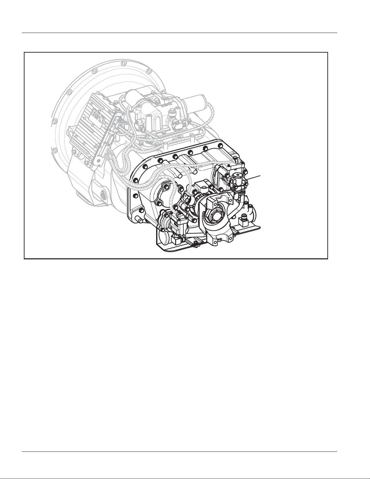
TRTS0062 Fault Isolation Procedure | Fault Code 28: Clutch System Fault
Transmission
Tramsmission
30-way Connector
Transmission
Controller
Component Identification
2013.07.17
© 2013 Eaton. All rights reserved
63
Page 68

Fault Code 28: Clutch System Fault Test | Fault Isolation Procedure TRTS0062
Fault Code 28: Clutch System Fault Test
Purpose: Check wet clutch fluid level.
A
1. Key on.
2. Place the transmission in neutral.
3. Allow engine to idle at 700–800 RPM for a mini-
mum of 2 minutes.
Note: Ensure transmission fluid temperature is 60
–120
° F (16°–49° C).
4. Check wet clutch fluid level.
• If fluid level is at or above the Cold-Full mark,
go to Step
• If fluid level is below the Cold-Add mark, cor-
rect fluid level. Go to Step
B.
V.
Purpose: Measure the resistance of the hydraulic
B
manifold through the Transmission Harness.
1. Key off.
2. Disconnect the Transmission Controller 30-way
connector.
3. Measure resistance between the Transmission Har-
ness 30-way connector:
°
- Pin K2 and Pin K3
- Pin J2 and Pin J3
321
K
J
H
G
F
E
D
C
B
A
321
OHMS
V
A
COM
321
K
J
H
G
F
E
D
C
B
A
321
OHMS
V
A
COM
• If the resistance between Pin K2 and Pin K3 is
6.5–9.5 ohms and the resistance between Pin
J2 and Pin J3 is 8.5–12 ohms, go to Step
C.
• If resistance is outside of range, go to Step D.
64
© 2013 Eaton. All rights reserved
2013.07.17
Page 69

TRTS0062 Fault Isolation Procedure | Fault Code 28: Clutch System Fault Test
Purpose: Test the Hydraulic Manifold for a short to
C
ground through the Transmission Harness.
1. Measure resistance between the Transmission Har-
ness 30-way connector:
- Pin K2 and ground
- Pin J2 and ground
OHMS
V
GROUND
321
K
J
H
G
F
E
D
C
B
A
321
OHMS
V
GROUND
A
COM
321
K
J
H
G
F
E
D
C
B
A
321
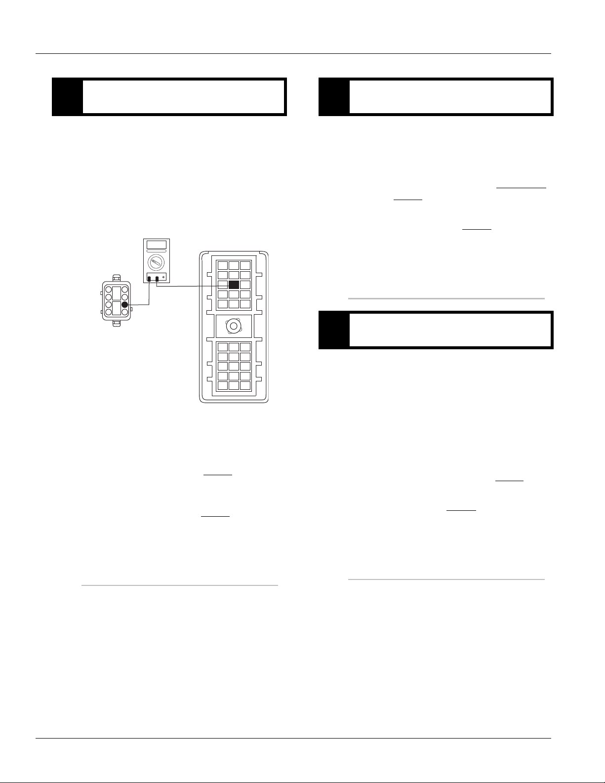
Purpose: Measure the resistance of the hydraulic
D
manifold switch.
1. Disconnect Transmission Harness located on left
side of wet clutch housing.
2. Measure resistance between wet clutch housing
connector pins:
- Pin 3 and Pin 4
- Pin 1 and Pin 2
A
COM
4
1
2
3
OHMS
V
A
COM
4321
OHMS
V
A
COM
• If the resistance between Pin 1 and Pin 2 is
8.5–12 ohms and the resistance between Pin 3
and Pin 4 is 6.5–9.5 ohms, go to Step
E.
• If resistance is outside of range, replace
Transmission
. Go to Step V.
• If resistance from Pin K2 to ground and Pin J2
to ground is more than 10K ohms or open circuit [OL], Replace Transmission
Code is Active). Go to Step
(Only if Fault
V.
• If resistance is less than 10K ohms, go to Step
D.
2013.07.17
© 2013 Eaton. All rights reserved
65
Page 70

Fault Code 28: Clutch System Fault Test | Fault Isolation Procedure TRTS0062
OHMS
V
COM
A
OHMS
V
COM
A
4
3
2
1
4
3
2
1
GROUND
GROUND
Purpose: Test the Hydraulic Manifold Switch for a
E
short to ground.
1. Measure resistance between wet clutch housing
connector pins:
- Pin 3 and ground
- Pin 1 and ground
• If resistance from Pin 3 to ground and Pin 1 to
ground is more than 10K ohms or open circuit
[OL], replace Transmission Harness
Step
V.
, Go to
• If resistance is less than 10K ohms, replace
Transmission
. Go to Step V.
Purpose: Verify repair.
V
1. Key off.
2. Reconnect all connectors.
3. Key on.
4. Clear codes, see “Clearing Fault Codes” on page 6.
5. Use Driving Techniques to attempt to reset the
code, see “Driving Techniques” on page 7.
6. Check for codes, see “Retrieving Fault Codes” on
page 5.
• If no codes, test complete.
• If Fault Code 28 appears, go to Step
error in testing.
• If code other than 28 appears, see “Fault Code
Isolation Procedure Index” on page 12.
A. to find
66
© 2013 Eaton. All rights reserved
2013.07.17
Page 71

TRTS0062 Fault Isolation Procedure | Fault Code 28: Clutch System Fault Test
2013.07.17
© 2013 Eaton. All rights reserved
67
Page 72

Fault Code 31: Momentary Engine Ignition Interrupt Relay (MEIIR) | Fault Isolation Procedure TRTS0062
Fault Code 31: Momentary Engine Ignition Interrupt Relay (MEIIR)
J1587:MID 130 SID 218 FMI 3,4
Overview
Fault Code 31indicates an electrical failure of the Momentary Engine Ignition Interrupt Relay (MEIIR) circuit.
Detection
The fault is detected during power up. The Shift Controller
checks the MEIIR circuit every time the system is powered
up. If the electrical characteristics of the circuit are incorrect, the fault code is set.
Conditions to Set Fault Code Active
Fallback
There is no fallback associated with this failure; however, if
the engine speed flares uncontrollably while the transmission is in a gear, the transmission may not be able to
achieve neutral if it is selected due to a torque lock condition.
Possible Causes
This fault code can be caused by any of the following:
• OEM wiring
• Electrical failure in the MEIIR circuit
• Mechanical failure in the MEIIR relay
• Shift Controller
Additional Tools
• Basic hand tools
• Eaton Test Adapter kit
• ServiceRanger
68
© 2013 Eaton. All rights reserved
2013.07.17
Page 73

TRTS0062 Fault Isolation Procedure | Fault Code 31: Momentary Engine Ignition Interrupt Relay (MEIIR)
Push Button Shift Control
Ignition
Interrupt
relay
30
86
87a
85
Engine ECM
87
30
86
85
87
87a
Gear display
1
2
3
4
Ignition power (switched power)
run to main power lead that
feeds the ignition bus (OEM
responsible for overcurrent
protection on this line)
10 AMP 12 volt only
automatic resetting
circuit breaker
Or
10 or 15 AMP
fuse
C1
H1
H3
Run to ignition
input on Engine
ECM
All OEM responsible wiring shown is "typical". Consult specific application.
(C1,Ignition Power, 30, 86, 87a) = +12 volt switched from ignition switch
(H3-87) = Signal returns
(H1-85) = -12 volt relay source
Component Identification
2013.07.17
© 2013 Eaton. All rights reserved
69
Page 74

Fault Code 31: Momentary Engine Ignition Interrupt Relay (MEIIR) Test | Fault Isolation Procedure TRTS0062
OHMS
V
COM
A
J
I
H
G
F
E
D
C
B
A
321
321
85
30
86
87
87a
J
I
H
G
F
E
D
C
B
A
321
321
Ground
OHMS
V
COM
A
Fault Code 31: Momentary Engine Ignition Interrupt Relay (MEIIR) Test
Purpose: Verify continuity of the Vehicle Harness
A
and test for a short to ground.
1. Key off.
2. Disconnect Shift Controller 30-way connector.
3. Remove the MEIIR relay from OEM Dash Harness.
4. Measure resistance between:
- Shift Controller 30-way connector Pin H1 and
relay connector Pin 85.
- Shift Controller 30-way connector Pin H1 and
ground.
Purpose: Verify continuity of the OEM Vehicle har-
B
ness and test for a short to ground.
1. Key off.
2. Measure resistance between:
- Shift Controller 30-way connector Pin H3 and
relay connector Pin 87.
- Shift Controller 30-way connector Pin H3 and
ground.
OHMS
321
J
I
H
G
F
E
D
C
B
A
321
A
V
COM
321
J
I
H
G
F
E
D
C
B
A
321
OHMS
V
COM
Ground
A
• If resistance between Pin H1 and Pin 85 is
0–0.3 ohms and if resistance between Pin H1
and ground is between 10K ohms and open
circuit [OL], go to Step
B.
• If resistance is outside of range, repair OEM
wiring from Shift Controller to MEIIR relay. Go
to Step
V.
87
86
85
87a
30
• If resistance between Pin H3 and Pin 87 is
0–0.3 ohms and if resistance between Pin H3
and ground is 10K ohms or open circuit [OL],
go to Step
C.
• If resistance is outside of range, repair OEM
wiring from Shift Controller to MEIIR relay. Go
to Step
V.
70
© 2013 Eaton. All rights reserved
2013.07.17
Page 75

TRTS0062 Fault Isolation Procedure | Fault Code 31: Momentary Engine Ignition Interrupt Relay (MEIIR) Test
Purpose: Measure signal voltage at the MEIIR re-
C
lay connector.
1. Reconnect Shift Controller 30-way connector.
2. Key on.
3. Measure voltage between MEIIR relay connector
Pin 86 and ground
87
86
85
87a
30
OHMS
V
A
COM
Ground
• If voltage is within 0.6 of battery voltage, go to
Step
D.
• If voltage is outside of range, repair OEM wir-
ing. Go to Step
V.
Purpose: Measure battery voltage to the MEIIR re-
D
lay.
1. Key on.
2. Measure voltage between MEIIR relay connector
Pin 30 and ground.
87
86
85
87a
30
OHMS
V
COM
A
Ground
• If voltage is within 0.6 of battery voltage,
Replace MEIIR relay (only if fault code is
Active), Go to Step
E.
• If resistance is outside of range, repair OEM
wiring, Go to Step
V.
2013.07.17
© 2013 Eaton. All rights reserved
71
Page 76

Fault Code 31: Momentary Engine Ignition Interrupt Relay (MEIIR) Test | Fault Isolation Procedure TRTS0062
Purpose: Check for Active or Inactive fault codes.
E
1. Key on.
2. Retrieve codes, see “Retrieving Fault Codes” on
page 5.
• If Fault Code 31 is Inactive, go to Step
• If Fault Code 31 is Active, replace Shift Control. Go to Step V.
V.
Purpose: Verify repair.
V
1. Key off.
2. Reconnect all connectors.
3. Key on.
4. Clear codes, see “Clearing Fault Codes” on page 6.
5. Use Driving Techniques to attempt to reset the
code, see “Driving Techniques” on page 7.
6. Check for codes, see “Retrieving Fault Codes” on
page 5.
• If no codes, test complete.
• If Fault Code 31 appears, go to Step
error in testing.
• If code other than 31 appears, see “Fault Code
Isolation Procedure Index” on page 12.
A. to find
72
© 2013 Eaton. All rights reserved
2013.07.17
Page 77

TRTS0062 Fault Isolation Procedure | Fault Code 31: Momentary Engine Ignition Interrupt Relay (MEIIR) Test
2013.07.17
© 2013 Eaton. All rights reserved
73
Page 78

Fault Code 32: Switched System Voltage | Fault Isolation Procedure TRTS0062
Fault Code 32: Switched System Voltage
J1587:MID 130 SID 62 FMI 4
Overview
Fault Code 32 indicates the switched system voltage from
the Shift Controller on Pin J2 and Pin K2 is below 7 volts.
Detection
The fault is detected immediately after power up.
Conditions to Set Fault Code Active
Fallback
This fault causes an in-place fallback.
Possible Causes
This fault code can be caused by any of the following:
• Low batteries
• OEM Harness
• Shift Controller
Additional Tools
• Basic hand tools
• Eaton Test Adapter kit
• Digital volt/ohm meter
74
© 2013 Eaton. All rights reserved
2013.07.17
Page 79

TRTS0062 Fault Isolation Procedure | Fault Code 32: Switched System Voltage
30 AMP fuse
Battery power
(non-switched power)
run to starter or batteries
All OEM responsible wiring shown is "typical". Consult specific application.
(B1, E2) = +12 volt switched from shift control to transmission controller.
VOLUME
CONTROL
SERVICE
SHIFT
EATON FULLER
TRANSMISSIONS
L
H
D
N
R
B1
E2
J2
K2
Vehicle bulkhead
connector
Shift control
30-way connector
Vehicle interface
18-way connector
Component Identification
2013.07.17
© 2013 Eaton. All rights reserved
75
Page 80

Fault Code 32: Switched System Voltage Test | Fault Isolation Procedure TRTS0062
A
B
+
–
+
–
+
–
+
–
Main Power Supply 2-Way Connector
20 Amp Fuse
30 Amp Fuse
Fault Code 32: Switched System Voltage Test
Purpose: Inspect the integrity of the fuse holder
A
and connections.
1. Key off.
2. Inspect main power 2-way connector terminals,
in-line fuse holder and power supply connections
for integrity and corrosion.
• If no problem found, go to Step
B.
• If problem is found, repair power/ground path
for the main power supply. Go to Step
V.
Purpose: Confirm the Vehicle Harness will carry a
B
proper load.
1. Key off.
2. Insert 20-amp fuse into main power supply 2-way
connector (at trans controller optional).
• If fuse blows immediately, go to Step
C.
• If fuse does not blow immediately, repair wir-
ing from the battery to the Transmission Controller. Go to Step
V.
76
© 2013 Eaton. All rights reserved
2013.07.17
Page 81

TRTS0062 Fault Isolation Procedure | Fault Code 32: Switched System Voltage Test
OHMS
V
COM
A
K
J
H
G
F
E
D
C
B
A
321
321
Purpose: Verify continuity of the Vehicle Harness.
C
1. Key off.
2. Disconnect negative (-) battery cable.
3. Disconnect the main power 2-way connector on the
Transmission Controller.
4. Disconnect Shift Controller 30-way connector.
5. Measure resistance between Shift Controller
30-way Pin J2 and Pin K2
Purpose: Verify repair.
V
1. Key off.
2. Reconnect all connectors.
3. Key on.
4. Clear codes, see “Clearing Fault Codes” on page 6.
5. Use Driving Techniques to attempt to reset the
code, see “Driving Techniques” on page 7.
6. Check for codes, see “Fault Code Retrieval/Clear-
ing” on page 5.
• If no codes, test complete.
• If Fault Code 32 appears, go to Step
error in testing.
• If code other than 32 appears, see “Fault Code
Isolation Procedure Index” on page 12.
A. to find
2013.07.17
• If resistance is 0–0.3 ohms, replace Shift Control (only if fault code is Active). Go to Step V.
• If resistance is outside of range, repair OEM
wiring from the Transmission Controller to
Shift Controller. Go to Step
V.
© 2013 Eaton. All rights reserved
77
Page 82

Fault Code 33: Battery Voltage Supply | Fault Isolation Procedure TRTS0062
Fault Code 33: Battery Voltage Supply
J1587:MID 130 PID 168 FMI 4
Overview
Fault Code 33 indicates the battery power supply to the
Shift Controller Pin J1 and Pin K1 is below 7 volts.
Detection
The fault is detected immediately after power up. This fault
causes the Service light to flash, but cannot be retrieved via
key clicks (because turning the ignition key off at this point
results in an immediate shutdown).
Conditions to Set Fault Code Active
Fallback
If this fault occures while moving, it causes a current gear
fallback. Once the vehicle is stopped, starting gear and
reverse can be engaged
Possible Causes
This fault code can be caused by any of the following:
• Battery bus fuse/circuit breaker is open
• Low batteries
• Damaged Vehicle Harness
• Malfunctioning Shift Controller
Additional Tools
• Basic hand tools
• Eaton Test Adapter kit
• Digital volt/ohm meter
78
© 2013 Eaton. All rights reserved
2013.07.17
Page 83

TRTS0062 Fault Isolation Procedure | Fault Code 33: Battery Voltage Supply
Component Identification
VOLUME
CONTROL
R
N
SERVICE
30 AMP fuse
Battery power
(non-switched power)
run to starter or batteries
Black
A1
A3
SHIFT
EATON FULLER
TRANSMISSIONS
J1
J3
D
H
L
Shift control
30-way connector
B3
E1
K3
K1
Vehicle bulkhead
connector
All OEM responsible wiring shown is "typical". Consult specific application.
(A1, E1) = +12 volt non-switched from battery
(A3, B3) = Signal returns, grounds, and general OEM wiring
2013.07.17
© 2013 Eaton. All rights reserved
79
Page 84

Fault Code 33: Battery Voltage Supply Test | Fault Isolation Procedure TRTS0062
A
B
+
–
+
–
+
–
+
–
Main Power Supply 2-Way Connector
20 Amp Fuse
30 Amp Fuse
Fault Code 33: Battery Voltage Supply Test
Purpose: Measure battery voltage. Visually inspect
the batteries, inline fuse and power and ground
A
supplies to the ECU.
1. Key off.
2. Inspect main power 2-way connector terminals,
in-line fuse holder and power supply connections
for integrity and corrosion.
• If no problem found, go to Step
B.
• If a problem is found, repair power/ground
path for the main power supply. Go to Step
V.
Purpose: Check for proper power supply at main
B
power 2-way connector.
1. Key off.
2. Insert 20-amp fuse into main power 2-way connec-
tor.
• If fuse blows immediately, go to Step
V.
• If fuse does not blow immediately, repair wir-
ing from the battery to the Transmission Controller. Go to Step
V.
80
Purpose: Verify repair.
V
1. Key on.
2. Retrieve codes, see “Retrieving Fault Codes” on
page 5.
• If Fault Code 33 is Active, see “Electrical Sys-
tem Pretest” on page 15.
• If Fault Code 33 is Inactive, test complete.
© 2013 Eaton. All rights reserved
2013.07.17
Page 85

TRTS0062 Fault Isolation Procedure | Fault Code 33: Battery Voltage Supply Test
2013.07.17
© 2013 Eaton. All rights reserved
81
Page 86

Fault Code 35: J1939 Data Link | Fault Isolation Procedure TRTS0062
Fault Code 35: J1939 Data Link
J1587:MID 130 SID 231 FMI 2
Overview
Fault Code 35 indicates the transmission failed to communicate with the engine over the J1939 data link.
Detection
Starting 75 seconds after key on and throughout the operation, the Shift Controller constantly communicates with the
engine ECM. If communication fails for more than 5 seconds, Fault Code 35 is set.
Conditions to Set Fault Code Active
Fallback
If the fault occurs while moving, it causes a current gear
fallback. Once vehicle has stopped, the starting gear and
reverse can be engaged. If the failure occurs at system initialization, it causes an AutoSelect fallback mode.
Possible Causes
This fault can be caused by any of the following:
• J1939 data link
• Engine ECM
• Vehicle Harness or Connections
• Engine Harness or Connections
• Excessive radio interference
• Shift Controller
Additional Tools
• Basic hand tools
• Eaton Test Adapter kit
• Digital volt/ohm meter
82
© 2013 Eaton. All rights reserved
2013.07.17
Page 87

TRTS0062 Fault Isolation Procedure | Fault Code 35: J1939 Data Link
Component Identification
Shift control
Detroit Diesel
Cummins
Engine ECM
Caterpillar
Mack
Typical J-1939/11 data link harness
(OEM supplied)
30-way connector
+J-1939
A
Shift control
–J-1939
B
C
Shield
2013.07.17
© 2013 Eaton. All rights reserved
83
Page 88

Fault Code 35: J1939 Data Link Test | Fault Isolation Procedure TRTS0062
K
J
H
G
F
E
D
C
B
A
321
321
OHMS
V
COM
A
engine ECM
K
J
H
G
F
E
D
C
B
A
321
321
OHMS
V
COM
A
GROUND
K
J
H
G
F
E
D
C
B
A
321
321
OHMS
V
COM
A
engine ECM
K
J
H
G
F
E
D
C
B
A
321
321
OHMS
V
COM
A
GROUND
Fault Code 35: J1939 Data Link Test
Purpose: Verify continuity of the OEM J1939 data
A
high (+) circuit and test for a short to ground.
1. Key off.
2. Disconnect Shift Controller 30-way connector.
3. Disconnect engine ECM connector which contains
the J1939 Data Link.
4. Measure resistance between:
- Shift Controller 30-way connector Pin G1 and
engine ECM pin (see OEM wiring for positive (+)
pin of J1939)
- Shift Controller 30-way Pin G1 and ground
Purpose: Verify continuity of the OEM J1939 data
B
low (-) circuit and test for a short to ground.
1. Key off.
2. Measure resistance between:
- Shift Controller 30-way connector Pin G2 and
engine ECM pin (see OEM wiring for negative (-)
pin of J1939)
- Shift Controller 30-way Pin G2 and ground
• If resistance between Pin G2 and engine ECM
pin (see OEM wiring for negative (-) pin of
J1939) is 0–0.3 ohms, and if resistance
between Pin G2 and ground is more than 10K
ohms or open circuit [OL] and:
- If equipped with J1939 Lite, go to Step
- If not equipped with J1939 Lite, go to Step
C.
D.
84
• If resistance between Pin G1 and engine ECM
pin (see OEM wiring for positive (+) J1939 pin)
is 0–0.3 ohms, and if resistance between Pin
• If resistance is outside of range, repair J1939
Data Link Harness between engine ECM and
Shift Controller, go to Step
V.
G1 and ground is more than 10K ohms or
open circuit [OL], go to Step
B.
• If resistance is outside of range, repair J1939
Data Link Harness between engine ECM and
Shift Controller, go to Step
V.
© 2013 Eaton. All rights reserved
2013.07.17
Page 89

TRTS0062 Fault Isolation Procedure | Fault Code 35: J1939 Data Link Test
K
J
H
G
F
E
D
C
B
A
321
321
OHMS
V
COM
A
Purpose: Verify continuity of the OEM J1939 data
C
(shield) circuit and test for a short to ground.
1. Key off.
2. Measure resistance between Shift Controller
30-way connector Pin G3 and engine ECM pin
number (see OEM wiring for J1939 shield pin).
321
K
J
H
G
F
OHMS
V
COM
A
Engine ECM
E
D
C
B
A
321
• If resistance between Pin G3 and engine ECM
pin (see OEM wiring for J1939 shield pin) is
0–0.3 ohms, go to Step
• If resistance is outside of range, repair J1939
Data Link Harness between engine ECM and
Shift Controller, go to Step
D.
V.
Purpose: Confirm the presence of the terminating
D
resistors on the OEM J1939 data link.
1. Key off.
2. Measure resistance between Shift Controller
30-way connector Pin G1 and Pin G2.
Note: Make sure the volt/ohm meter is on the
proper scale (around 200 ohm scale).
• If resistance between Pin G1 and Pin G2 is
between 50–70 ohms, go to Step
V.
• If resistance is more than 70 ohms, 1 or more
of the terminating resistors on the J1939 data
link harness is either missing or out of range.
Repair J1939 Data Link Harness, go to Step
V.
2013.07.17
• If resistance is less than 50 ohms, repair the
J1939 Data Link between the engine ECM and
the Shift Controller, go to Step
© 2013 Eaton. All rights reserved
V.
85
Page 90

Fault Code 35: J1939 Data Link Test | Fault Isolation Procedure TRTS0062
Purpose: Verify repair.
V
1. Key off.
2. Key on.
3. Clear codes, see “Clearing Fault Codes” on page 6.
4. Use Driving Techniques to attempt to reset the
code, see “Driving Techniques” on page 7.
5. Check for codes, see “Retrieving Fault Codes” on
page 5.
• If no codes, test complete.
• If Fault Code 35 appears, go to Step
error in testing.
• If code other than 35 appears, see “Fault Code
Isolation Procedure Index” on page 12.
A. to find
86
© 2013 Eaton. All rights reserved
2013.07.17
Page 91

TRTS0062 Fault Isolation Procedure | Fault Code 35: J1939 Data Link Test
2013.07.17
© 2013 Eaton. All rights reserved
87
Page 92

Fault Code 41: Range Failed to Engage | Fault Isolation Procedure TRTS0062
Fault Code 41: Range Failed to Engage
J1587:MID 130 SID 56 FMI 7
Overview
Fault Code 41 indicates the transmission is unable to complete a shift across the range. The range is either stuck in HI
or LO, or cannot complete engagement into HI or LO.
Detection
The transmission attempts the same range shift 5 consecutive times and determines the shift cannot be completed
based on the speeds across the back box.
Conditions to Set Fault Code Active
Fallback
This fault causes a 5-speed fallback and the transmission
stays in either LO range or HI range. When the vehicle
comes to a stop, an attempt to shift into LO range is made.
Possible Causes
This fault code can be caused by any of the following:
• Low air pressure
• Contaminated air supply
• Air leak
• Range valve
• Range Synchronizer
• Range Actuator, Cylinder, Piston or Yoke
Additional Tools
• Basic hand tools
• Two 0-100 PSI Air Pressure gauges
88
© 2013 Eaton. All rights reserved
2013.07.17
Page 93

TRTS0062 Fault Isolation Procedure | Fault Code 41: Range Failed to Engage
Component Identification
HI diagnostic port
Range system
LO diagnostic port
(on opposite side of
HI diagnostic port,
out of view)
2013.07.17
© 2013 Eaton. All rights reserved
89
Page 94

Fault Code 41: Range Failed to Engage Test | Fault Isolation Procedure TRTS0062
LO range
0-100 PSI gauge
HI range
0-100 PSI gauge
Fault Code 41: Range Failed to Engage Test
Purpose: Measure LO range air pressure.
A
1. Key off.
2. Install both 0-100 PSI air pressure gauges into the
range cover diagnostic ports.
3. Start engine and allow air pressure to build to gov-
ernor cut off.
4. Release clutch to register Input Shaft speed in the
transmission.
5. Turn off engine, but leave key on.
6. Select reverse with Shift Controller, then select
neutral.
Purpose: Measure HI range air pressure.
B
1. Key on.
2. With Shift Controller, select reverse, press the
up-shift button, then select neutral.
Note: If the Gear Display does not read “H”
(10-speed) or “IH” (18-speed), go to the Up-Down
Button Test.
HI range
0-100 PSI gauge
LO range
0-100 PSI gauge
90
• If LO range air pressure gauge is between
55–65 PSI, and the HI range air pressure
gauge is at 0 PSI, go to Step
• If neither air pressure gauge reads as listed
above, replace Range Valve
der Cover as required. Go to Step
B.
and Range Cylin-
V.
© 2013 Eaton. All rights reserved
or
10-Speed
• If HI range air pressure gauge is between
55–65 PSI and LO air pressure gauge is at 0
PSI, repair range system as required. Go to
Step
V.
• If neither air pressure gauge reads as listed
above, replace Range Valve
der Cover as required. Go to Step
18-Speed
and Range Cylin-
V.
2013.07.17
Page 95

TRTS0062 Fault Isolation Procedure | Fault Code 41: Range Failed to Engage Test
Purpose: Verify repair.
V
1. Key off.
2. Remove all gauges.
3. Key on.
4. Clear codes, see “Clearing Fault Codes” on page 6.
5. Use Driving Techniques to attempt to reset the
code, see “Driving Techniques” on page 7.
6. Check for codes, see “Retrieving Fault Codes” on
page 5.
• If no codes, test complete.
• If Fault Code 41 appears, go to Step
error in testing.
• If a code other than 41 appears, see “Fault
Code Isolation Procedure Index” on page 12.
A. to find
2013.07.17
© 2013 Eaton. All rights reserved
91
Page 96

Fault Code 42: Splitter Failed to Engage | Fault Isolation Procedure TRTS0062
Fault Code 42: Splitter Failed to Engage
J1587:MID 130 SID 61 FMI 7
Overview
Fault Code 42 indicates the transmission is unable to complete a shift across the Splitter. The Splitter is either stuck in
HI or LO, or cannot complete engagement into HI or LO.
Detection
The transmission attempts the same splitter shift 5 consecutive times and determines the shift cannot be completed
based on the speeds across the back box.
Conditions to Set Fault Code Active
Fallback
This fault causes a 9-speed fallback and the transmission
stays in either LO split or HI split.
Possible Causes
This fault code can be caused by any of the following:
• Low air pressure
• Contaminated air supply
• Air leak
• Splitter valve
• Splitter Actuator, Cylinder, Piston or Yoke
Additional Tools
• Basic hand tools
• Two 0-100 PSI Air Pressure gauges
92
© 2013 Eaton. All rights reserved
2013.07.17
Page 97

TRTS0062 Fault Isolation Procedure | Fault Code 42: Splitter Failed to Engage
Splitter system
HI diagnostic port
LO diagnostic port
Component Identification
2013.07.17
© 2013 Eaton. All rights reserved
93
Page 98

Fault Code 42: Splitter Failed to Engage Test | Fault Isolation Procedure TRTS0062
LO split
0-100 PSI gauge
HI split
0-100 PSI gauge
Fault Code 42: Splitter Failed to Engage Test
Purpose: Measure LO Splitter air pressure.
A
1. Key off.
2. Install both 0-100 PSI air pressure gauges into the
Splitter cover diagnostic ports.
3. Start vehicle and allow air pressure to build to gov-
ernor cut off.
4. Turn off engine, but leave key on.
5. With Shift Controller, select reverse, then select
neutral.
Note: Five minutes is allowed for checking the
pressure after moving the Shift Lever to neutral.
Purpose: Measure HI Splitter air pressure.
B
1. Key on.
2. With Shift Controller, select reverse, press the up
shift button, then select neutral.
Note: If the Gear Display does not read “IH”
(18-speed), see “Up/Down Button Test” on
page 256.
LO split
0-100 PSI gauge
HI split
0-100 PSI gauge
• If HI Splitter gauge measures 55–65 PSI and if
LO Splitter gauge measures 0 PSI, go to Step
B.
• If neither air pressure gauges do not read as
listed above, replace Splitter Valve
ter Cylinder Cover as required. Go to Step
and Split-
V.
• If LO Splitter gauge measures 55–65 PSI and if
HI Splitter gauge measures 0 PSI, repair
Mechanical Splitter system as required, go to
Step
V.
• If neither air pressure gauges do not read as
listed above, replace Splitter Valve
ter Cylinder Cover as required. Go to Step
and Split-
V.
94
© 2013 Eaton. All rights reserved
2013.07.17
Page 99

TRTS0062 Fault Isolation Procedure | Fault Code 42: Splitter Failed to Engage Test
Purpose: Verify repair.
V
1. Key off.
2. Remove all air pressure gauges.
3. Key on.
4. Clear codes, see “Clearing Fault Codes” on page 6.
5. Use Driving Techniques to attempt to reset the
code, see “Driving Techniques” on page 7.
6. Check for codes, see “Retrieving Fault Codes” on
page 5.
• If no codes, test complete.
• If Fault Code 42 appears, go to Step
error in testing.
• If code other than 42 appears, see “Fault Code
Isolation Procedure Index” on page 12.
A. to find
2013.07.17
© 2013 Eaton. All rights reserved
95
Page 100

Fault Code 43: Range Valve | Fault Isolation Procedure TRTS0062
Fault Code 43: Range Valve
J1587:MID 130 SID 35, 36 FMI 3, 4, 5
Overview
Fault Code 43 indicates an electrical failure of the solenoids
that control the range shift.
Detection
Starting at key on and throughout operation, the Transmission Controller constantly measures this Range Valve circuit. A failure of short to battery, short to ground or open
circuit is detected.
Conditions to Set Fault Code Active
Fallback
This fault causes a 5-speed fallback and the transmission
stays in either low range or high range. When the vehicle
comes to a stop, an attempt to shift into low range is made.
Possible Causes
This fault code can be caused by any of the following:
• Range Valve
• Transmission Harness
• Transmission Controller
Additional Tools
• Basic hand tools
• Eaton Test Adapter kit
• Digital volt/ohm meter
96
© 2013 Eaton. All rights reserved
2013.07.17
 Loading...