

Page 1

Troubleshooting Guide
Fuller Automated Transmissions
TRTS0050 EN-US
November 2015
RTAO-11710B-AC
RTAO-11710C-AC
RTAO-12710B-AC
RTAO-12710C-AC
RTAO-13710B-AC
RTAO-13710C-AC
RTAO-14710B-AC
RTAO-14710B-AS
RTAO-14710C-AC
RTAO-14710C-AS
RTAO-15710B-AC
RTAO-15710C-AC
RTAO-16710B-AC
RTAO-16710B-AS
RTAO-16710C-AC
RTAO-16710C-AS
RTLO-14918B-AS
RTLO-16918B-AS
RTLO-18918B-AS
RTLO-20918B-AS
Page 2

Warnings and Cautions
WARNING
CAUTION
WARNING
CAUTION
Warnings and Cautions
Follow the specified procedures in the indicated order to avoid personal injury.
Follow the specified procedures in the indicated order to avoid equipment malfunction or damage.
Note: Additional relevant information not covered in the service procedure.
Before starting a vehicle:
1. Sit in the driver's seat
2. Place shift lever in neutral
3. Set the parking brake
Before working on a vehicle or leaving the cab with engine running:
4. Place shift lever in neutral
5. Set the parking brake
6. Block the wheels
When parking the vehicle or leaving the cab:
7. Place shift lever in neutral
8. Set the parking brake
Do not release the parking brake or attempt to select a gear until the air pressure is at the correct level.
To avoid damage to the transmission during towing:
9. Place shift lever in neutral
10. Lift the drive wheels off of the ground or disconnect the driveling
Do not operate vehicle if alternator lamp is lit or if gauges indicate low voltage.
Page 3

Warnings and Cautions
Service Procedure
2-1
Page 4

Table of Contents
Section 1: General Information
Suggested Tools ................................ ......................1-1
Transmission Models Included ................................1-2
Diagnostic Procedure ...............................................1-3
Fault Code Retrieval/Clearing ...................................1-4
Driving Techniques ..................................................1-6
Fault Code Isolation Procedure Index .....................1-10
Symptom Driven Diagnostics Index .......................1-11
Section 2: Fault Isolation Procedures
Electrical System Pretest ..........................................2-1
Power-Up Sequence Pretest ....................................2-3
Air Pretest ................................................................2-9
Component Code: 11 (SID 254, FMI 2,12)
System Manager .............................................2-13
Code 11 (SID 254, FMI 2,12),
System Controller Test ...................................2-14
Component Code: 12 (SID 233, FMI 12)
Transmission ECU ..........................................2-15
Code 12 (SID 233, FMI 12),Transmission
ECU Test ...... ...................................................2-16
Component Code: 13 (SID 236, FMI 4,5)
Power Connect Relay Coil ............................... 2-17
Code 13 (SID 236, FMI 4,5),
Power Connect Relay Coil Test .......................2-18
Component Code: 14 (SID 18, FMI 12)
Shift Lever ......................................................2-21
Code 14 (SID 18, FMI 12), Shift Lever Test ............2-22
Component Code: 15 (SID 57, FMI 2)
Shift Lever Data Link .......................................2-25
Code 15 (SID 57, FMI 2),
Shift Lever Data Link Test ...............................2-26
Component Code: 16 (SID 248, FMI 2)
Eaton Proprietary Link (EPL) ..........................2-31
Code 16 (SID 248, FMI 2),
Eaton Proprietary Link (EPL) Test ...................2-32
Component Code: 17 (SID 237, FMI 4)
Start Enable Relay Coil ....................................2-43
Code 17(SID 237,FMI 4),
Start Enable Relay Coil Test ............................2-44
Component Code: 31 (PID 62, FMI 3,4)
Engine Brake Relay Coil ..................................2-47
Code 31 (PID 62, FMI 3,4),
Engine Brake Relay Coil Test ...........................2-48
Component Code: 33 (PID 168, FMI 4)
Battery Voltage Supply ....................................2-51
Code 33 (PID 168, FMI 4),
Battery Voltage Supply Test ...........................2-52
System Code: 35 (SID 231, FMI 2,7)
Engine Control Failure ....................................2-55
Code 35 (SID 231, FMI 2,7),
Engine Control Failure Test .............................2-56
System Code: 41 (SID 56, FMI 7)
Range Failed to Engage ..................................2-63
Code 41 (SID 56, FMI 7)
, Range Failed to Engage Test .........................2-64
System Code: 42 (SID 61, FMI 7)
Splitter Failed to Engage ................................. 2-67
Code 42 (SID 6,1, FMI 7),
Splitter Failed to Engage Test .........................2-68
Component Code: 43 (SID 35,36, FMI 3,4,5)
Range Solenoid Valve .....................................2-71
Code 43 (SID 35,36, FMI 3,4,5),
Range Solenoid Valve Test .............................2-72
Component Code: 44 (PID 54, FMI 3,4,5)
In
ertia Brake Solenoid Coil ............................. 2-77
Code 44 (PID 54, FMI 3,4,5),
ertia Brake Solenoid Coil Test ...................... 2-78
In
Component Code: 46 (SID 37,38, FMI 4,5)
Splitter Solenoid Valve ...................................2-83
Code 46 (SID 37,38, FMI 4,5),
Splitter Solenoid Valve Test ............................ 2-84
Component Code: 51 (PID 60, FMI 2)
Rail Select Sensor ....................................... ...2-89
Code 51 (PID 60, FMI 2),
Rail Select Sensor Test ..................................2-90
Component Code: 52 (PID 59, FMI 2)
Gear Select Sensor .........................................2-99
Code 52 (PID 59, FMI 2),
Gear Select Sensor Test ..............................2-100
Component Code: 53 (SID 34, FMI 2)
Reverse Ball Switch ...................................... 2-109
Code 53 (SID 34, FMI 2),
Reverse Ball Switch Test ............................. 2-110
Component Code: 56 (PID 161, FMI 2)
Input Shaft Speed Sensor .............................2-115
Code 56 (PID 161, FMI 2),
Input Shaft Speed Sensor Test .................... 2-116
Component Code: 57 (PID 160, FMI 2)
Main Shaft Speed Sensor .............................2-119
Code 57 (PID 160, FMI 2),
Main Shaft Speed Sensor Test .....................2-120
Component Code: 58 (PID 191, FMI 2)
Output Shaft Speed Sensor ..........................2-123
Code 58 (PID 191, FMI 2),
Output Shaft Speed Sensor Test ...................2-124
Component Code: 61 (SID 39, FMI 5,6)
Rail Select Motor ..........................................2-127
Code 61 (SID 39, FMI 5,6),
Rail Select Motor Test ..................................2-128
Component Code: 63 (SID 40, FMI 5,6)
Gear Select Motor .........................................2-133
Page 5

Table of Contents
Table of Contents
Code 63 (SID 40, FMI 5,6),
Gear Select Motor Test .................................2-134
Component Code: 65 (SID 251, FMI 4)
Low Motor Voltage .......................................2-139
Code 65 (SID 251, FMI 4),
Low Motor Voltage Test ...............................2-140
System Code: 71 (SID 60, FMI 7)
Stuck Engaged .............................................. 2-143
Code 71 (SID 60, FMI 7), Stuck Engaged Test .....2-144
System Code: 72 (SID 59, FMI 7)
Failed to Select Rail .......................................2 -149
Code 72 (SID 59, FMI 7),
Failed to Select Rail Test ...............................2-150
System Code: 73 (SID 58, FMI 7)
Failed to Engage Gear ...................................2-153
Code 73 (SID 58, FMI 7),
Failed to Engage Gear Test ...........................2-154
System Code: 74 (SID 54, FMI 7)
Failed to Sync Initial Engagement .................2-157
Code 74 (SID 54, FMI 7),
Failed to Sync Initial Engagement Test ..........2-158
Component Code: 83 (SID 18, FMI 14)
Shift Lever Missing .......................................2-161
Code 83 (SID 18, FMI 14),
Shift Lever Missing Test ...............................2-162
Appendix
Current Style Wiring Harness AutoSelect ................A-1
Current Style Wiring Harness AutoShift ...................A-3
Old Style Wiring Harness AutoSelect .......................A-5
Old Style Wiring Harness AutoShift .........................A-7
Check for Proper Clutch Operation ..........................A-9
Confirm Proper Clutch Adjustment ........................ A-10
Section 3: Symptom Isolation Procedures
Electrical System ......................................................3-1
Electrical System Test ..............................................3-2
Front Box Control ...................................................3-17
Front Box Control Test ...........................................3-18
Gear Display Power Supply ....................................3-29
Gear Display Power Supply Test ............................3-30
Start Enable Relay Contact .....................................3-37
Start Enable Relay Contact Test .............................3-38
AutoShift/AutoSelect Will Not Engage a Gear .........3-41
AutoShift/AutoSelect Will Not Engage a Gear Test .3-42
J-1587 Data Link ....................................................3-49
J-1587 Data Link Test ............................................3-50
Range System ........................................................3-57
Range System Test ................................................3-58
Splitter System ........................................... ... .........3-61
Splitter System Test ...............................................3-62
Up/Down Button ............................................ ... ......3-65
Up/Down Button Test .............................................3-66
AutoShift/AutoSelect Shift Complaint ..................... 3-67
AutoShift/AutoSelect Shift Complaint Test .............3-68
Transmission Air Leak ........................................... .3-73
Transmission Air Leak Test ....................................3-74
Neutral Lock Input ..................................................3-79
Neutral Lock Input Test ..........................................3-80
Page 6

Suggested Tools
Air Gauges
• 2 (0-100) PSI Air Gauges
Volt/Ohm Meter
• SPX / Kent-Moore 1 (800) 328-6657
• P/N 5505027
PC-based Service Tool “ServiceRanger”
• Contact your OEM
Data Link Tester
• Eaton Service Parts 1 (800) 826-HELP (826-4357)
General Information
• P/N MF-KIT-04
Download Harness Kit
• Eaton Service Parts 1 (800) 826-HELP (826-4357)
• K-3481
Test Adapter Kit
• SPX / Kent-Moore 1 (800) 328-6657
• Eaton Test Adapter Kit P/N J-43318
• Serial Link Adapter Kit P/N J-38351-B
For more information call 1-800-826-HELP (826-4357)
1-1
Page 7

General Information
Transmission Models Included
18-Speed
General Information
10-Speed
1-2
Page 8

General Information
Diagnostic Procedure
Follow the flow cart below for all AutoSelect/AutoShift failures. Perform tests and procedures as directed by the flowchart.
Key on.
Retrieve active codes. Note: Scan tool
or P.C. may be required if service light
is not avialable.
• Perform Electrical System Pretest
Active codes?
YES
NO
• Refer to the Fault Code Isolation
Procedure Index to select a Fault
Code Isolation Procedure
Observe Gear Display
Can a solid "N"
be observed in
Gear Display ?
YES
Retrieve Inactive Codes.
Inactive Codes?
NO
NO
YES
Will engine crank ?
YES
• Perform Gear Display Test
• Record and clear codes
• Perform Driving Technique to reproduce
the inactive fault code
• Perform Electrical System Pretest
• Perform Air Pretest
• Refer to the Fault Code Isolation
Procedure Index to select
a fault code isolation procedure
• Perform Power-Up Sequence Pretest
• Perform Front Box Control Test
NO
1-3
Symptom?
NO
Test complete.
YES
• Perform Electrical System Pretest
• Perform Air Pretest
• Perform Power-Up Sequence Pretest
• Refer to Symptom-Driven Diagnostics
Table to select a symptom isolation procedure
Page 9

General Information
General Information
SERVICE
1 Flash
Short
pause
(1/2 sec)
Short
pause
(1/2 sec)
Long Pause
(3-4 sec)
3 Flashes
2 Flashes
Code 13 Code 21
SERVICE
SERVICE
SERVICE SERVICE
SERVICE
1 Flash
SERVICE
Fault Code Retrieval/Clearing
Retrieving Fault Codes
Retrieve fault codes by enabling the system’s self-diagnostic mode.
Note: You can also use a PC- based service tool, such as the ServiceRanger to retrieve fault codes.
1. Place the shift lever in neutral.
2. Set the parking brake.
3. Turn the ignition key on but do not start the engine. If the engine already running, you may still retrieve codes, however,
do not engage the starter if the engine stalls.
4. To Retrieve Active Codes: Start with the key in the on position. Turn the key off and on two times within five seconds
ending with the key in the on position. After five seconds, the service lamp begins flashing two-digit fault codes. If no
faults are active, the service light will not flash.
2 times
off
on
5. To Retrieve Inactive Codes: Start with the key in the on position. Turn the key off and on four times within five seconds
ending with the key in the on position. After five seconds, the service lamp begins flashing two-digit fault codes. If there
are no inactive faults, the service light will not flash.
6. Observe the sequence of flashes on the indicator lamp and record the codes. A one to two second pause separates each
stored code, and the sequence automatically repeats after all codes have been flashed.
off
4 times
on
1-4
Page 10

General Information
Clearing Fault Codes
The following procedure clears all inactive fault codes from the ECU’s memory. Active fault codes are automatically cleared when
the fault has been corrected.
Note: You may use a PC-based Service Tool, such as ServiceRanger, to clear fault codes.
1. Place the shift lever in neutral.
2. Set the parking brake.
3. Turn the ignition key on but do not start the engine.
4. Start with the key in the on position. Turn the key off and on six times within five seconds ending with the key in the on
position.
6 times
off
Note: If the codes have been successfully cleared, the service lamp will come on and stay on for five seconds.
5. Turn key off and allow the system to power down.
on
1-5
Page 11

General Information
Driving Techniques
General Information
Fault
Codes
11 254 2,12 System Control-
12 233 12 Transmission
13 236 4,5 Power Connect
14 18 12 Shift Lever Component Key on. If the fault is present, the system should
PID SID FMI Description Type of Code Driving Technique
Component Key on. If the fault is present, the system should
ler
Component Key on. If the fault is present, the system should
Controller
Component Key on. If the fault is present, the system should
Relay Coil
automatically detect the problem and set the code.
If the fault is not present at key on, operate the vehicle and attempt to duplicate the driving conditions that triggered the fault code. Possible
triggers include heat and vibration.
automatically detect the problem and set the code.
If the fault is not present at key on, operate the vehicle and attempt to duplicate the driving conditions that triggered the fault code. Possible
triggers include heat and vibration.
automatically detect the problem and set the code.
If the fault is not present at key on, operate the vehicle and attempt to duplicate the driving conditions that triggered the fault code. Possible
triggers include heat and vibration.
automatically detect the problem and set the code.
If the fault is not present at key on, operate the vehicle and attempt to duplicate the driving conditions that triggered the fault code. Possible
triggers include heat, vibration and selecting different shift lever positions.
15 57 2 Shift Lever Data
16 248 2 Eaton
17 237 4 Start Enable
Link
Proprietary Link
(EPL)
Relay Coil
Component Key on. If the fault is present, the system should
automatically detect the problem and set the code.
If the fault is not present at key on, operate the vehicle and attempt to duplicate the driving conditions that triggered the fault code. Possible
triggers include heat and vibration.
Component Key on. If the fault is present, the system should
automatically detect the problem and set the code.
If the fault is not present at key on, operate the vehicle and attempt to duplicate the driving conditions that triggered the fault code. Possible
triggers include heat and vibration.
Component Key on. If the fault is present, the system should
automatically detect the problem and set the code.
If the fault is not present at key on, operate the vehicle and attempt to duplicate the driving conditions that triggered the fault code. Possible
triggers include heat and vibration.
1-6
Page 12

General Information
Fault
Codes
31 62 3,4 Engine Brake Re-
33 168 4 Battery Voltage
35 231 2,7 Engine Control
41 56 7 Range Failed to
PID SID FMI Description Type of Code Driving Technique
lay Coil
Supply
Failure
Engage
Component Key on. If the fault is present, the system should
automatically detect the problem and set the code.
If the fault is not present at key on, operate the vehicle and attempt to duplicate the driving conditions that triggered the fault code. Possible
triggers include heat and vibration.
Component Key on. If the fault is present, the system should
automatically detect the problem and set the code.
If the fault is not present at key on, operate the vehicle and attempt to duplicate the driving conditions that triggered the fault code. Possible
triggers include heat and vibration.
System Key on. If the fault is present, the system should
automatically detect the problem and set the code.
If the fault is not present at key on, operate the vehicle and attempt to duplicate the driving conditions that triggered the fault code. Possible
triggers include heat, vibration and varying levels
of throttle demand.
System Operate the vehicle and perform several range up-
shifts and downshifts. The failure is detected after
5 consecutive attempts to complete the same type
of range shift. Several shifts (ten or more) may be
necessary before the ECU confirms the failure.
42 61 7 Splitter Failed to
Engage
43 35 or 36 3,4,5 Range Solenoid
Valve
44 54 3,4,5 Interia Brake So-
lenoid Coil
46 37 or 38 4,5 Splitter Solenoid
Valve
System Operate the vehicle and perform several range up-
shifts and downshifts. The failure is detected after
5 consecutive attempts to complete the same type
of range shift. Several shifts (ten or more) may be
necessary before the ECU confirms the failure.
Component Key on. If the fault is present, the system should
automatically detect the problem and set the code.
If the fault is not present at key on, operate the vehicle and attempt to duplicate the driving conditions that triggered the fault code. Possible
triggers include heat and vibration.
Component Key on. If the fault is present, the system should
automatically detect the problem and set the code.
If the fault is not present at key on, operate the vehicle and attempt to duplicate the driving conditions that triggered the fault code. Possible
triggers include heat and vibration.
Component Key on. If the fault is present, the system should
automatically detect the problem and set the code.
If the fault is not present at key on, operate the vehicle and attempt to duplicate the driving conditions that triggered the fault code. Possible
triggers include heat and vibration.
1-7
Page 13

General Information
General Information
Fault
Codes
51 60 2 Rail Select Sen-
52 59 2 Gear Select Sen-
53 34 2 Reverse Ball
56 161 2 Input Shaft
57 160 2 Main Shaft
PID SID FMI Description Type of Code Driving Technique
sor
sor
Switch
Speed Sensor
Speed Sensor
Component Key on. If the fault is present, the system should
automatically detect the problem and set the code.
If the fault is not present at key on, operate the vehicle and attempt to duplicate the driving conditions that triggered the fault code. Possible
triggers include heat and vibration.
Component Key on. If the fault is present, the system should
automatically detect the problem and set the code.
If the fault is not present at key on, operate the vehicle and attempt to duplicate the driving conditions that triggered the fault code. Possible
triggers include heat and vibration.
Component Select a reverse gear (repeatedly).
Component Select a forward gear and drive at a steady speed
no slower than 10 m.p.h. It may be necessary to
operate the vehicle for a prolonged period of time
if the cause of failure is related to heat and vibration.
Component Select a forward gear and drive at a steady speed
no slower than 10 m.p.h. It may be necessary to
operate the vehicle for a prolonged period of time
if the cause of failure is related to heat and vibration.
58 191 2 Output Shaft
61 39 5,6 Rail Select Motor Component Key on. If the fault is present, the system should
63 40 5,6 Gear Select Mo-
Speed Sensor
tor
Component Select a forward gear and drive at a steady speed
no slower than 10 m.p.h. It may be necessary to
operate the vehicle for a prolonged period of time
if the cause of failure is related to heat and vibration.
automatically detect the problem and set the code.
If the fault is not present at key on, operate the vehicle and attempt to duplicate the driving conditions that triggered the fault code. Possible
triggers include heat and vibration.
Component Key on. If the fault is present, the system should
automatically detect the problem and set the code.
If the fault is not present at key on, operate the vehicle and attempt to duplicate the driving conditions that triggered the fault code. Possible
triggers include heat and vibration.
1-8
Page 14

General Information
Fault
Codes
65 251 4 Low Motor Volt-
71 60 7 Stuck Engaged System Engage LO gear and allow the vehicle to slowly
72 59 7 Failed to Select
73 58 7 Failed to Engage
PID SID FMI Description Type of Code Driving Technique
Component Key on. If the fault is present, the system should
age
System Complete several shifts while the vehicle is in mo-
Rail
System Complete several shifts while the vehicle is in mo-
Gear
automatically detect the problem and set the code.
If the fault is not present at key on, operate the vehicle and attempt to duplicate the driving conditions that triggered the fault code. Possible
triggers include heat and vibration.
move forward. While the vehicle is in motion,
move the shift lever to Reverse LO and slowly
bring the vehicle to a stop. The vehicle will shift
into Reverse LO. Several shifts (ten or more) may
be necessary before the ECU confirms the failure.
tion, including selections from neutral. Allow the
transmission to complete several automatic
shifts.
tion, including selections from neutral. Allow the
transmission to complete several automatic
shifts.
74 54 7 Failed to Syn Ini-
tial Engagement
83 18 14 Shift Lever Miss-
ing
System With vehicle stopped, select a drive gear and fully
depress the clutch pedal. Return transmission to
neutral. Repeat several times.
Component Key on. If the fault is present, the system should
automatically detect the problem and set the code.
If the fault is not present at key on, operate the vehicle and attempt to duplicate the driving conditions that triggered the fault code. Possible
triggers include heat and vibration.
1-9
Page 15
General Information
Fault Code Isolation Procedure Index
General Information
Fault
Codes
11 254 2,12 System Controller Component 2-13
12 233 12 Transmission Controller Component 2-15
13 236 4, 5 Power Connect Relay Coil Component 2-17
14 18 12 Shift Lever Component 2-21
15 57 2 Shift Lever Data Link Component 2-25
16 248 2 Eaton Proprietary Link Component 2-31
17 237 4 Start Enable Relay Coil Component 2-43
31 62 3,4 Engine Brake Relay Coil Component 2-47
33 168 4 Battery Voltage Supply Component 2-51
35 231 2,7 Engine Control Failure System 2-55
41 56 7 Range Failed to Engage System 2-63
42 61 7 Splitter Failed to Engage System 2-67
43 35 or
44 54 3,4,5 Inertia Brake Solenoid Coil Component 2-77
S I D P I D FM I
3,4,5 Range Solenoid Valve Component 2-71
36
Description Type of Code Page Number
46 37 or
38
51 60 2 Rail Select Sensor Component 2-89
52 59 2 Gear Select Sensor Component 2-99
53 34 2 Reverse Ball Switch Component 2-109
56 161 2 Input Shaft Speed Sensor Component 2-115
57 160 2 Main Shaft Speed Sensor Component 2-119
58 191 2 Output Shaft Speed Sensor Component 2-123
61 39 5,6 Rail Select Motor Component 2-127
63 40 5,6 Gear Select Motor Component 2-133
65 251 4 Low Motor Voltage Component 2-139
71 60 7 Stuck Engaged System 2-143
72 59 7 Failed to Select Rail System 2-149
73 58 7 Failed to Engage Gear System 2-153
74 54 7 Failed to Sync Initial Engagement System 2-157
83 18 14 Shift Lever Missing Component 2-161
4,5 Splitter Solenoid Valve Component 2-83
1-10
Page 16
General Information
Symptom Driven Diagnostics Index
Symptom Isolation Procedure Page Number
Electrical System Test Electrical System Test 3-1
If "-" is displayed on the Gear Display, and there are no
active or inactive codes
If the Gear Display is not working, and there are no ac-
tive or inactive codes
If the engine does not start with the Shift Lever is in
neutral, and there are no active or inactive codes
If the transmission does not engage a gear, and there
are no active or inactive codes
If the PC-based Service Tool does not work J-1587 Data Link Test 3-49
If the transmission does not perform range shifts, and
there are no active or inactive fault codes
If the transmission does not perform Splitter Shifts,
and there are no active or inactive fault codes
If unable to shift the transmission with the Up/Down
Buttons, and there are no Active or Inactive codes
If a shift complaint exists and there are no Active or
Inactive codes
If the transmission has an air leak and there are no
Active or Inactive fault codes
If the Auto Neutral feature is not working Neutral Lock Input Test 3-79
Front Box Control Test 3-17
Gear Display Power Supply Test 3-29
Start Enable Relay Contact Test 3-37
AutoShift/AutoSelect will not Engage a Gear Test 3-41
Range System Test 3-57
Splitter System Test 3-61
Up/Down Button Test 3-65
AutoShift/AutoSelect Shift Complaint Test 3-67
Transmission Air Leak Test 3-73
1-11
Page 17

General Information
General Information
This page left blank intentionally.
1-12
Page 18

Electrical System Pretest
Fault Isolation Procedures
Overview
The test does not relate to any specific fault code, but must be
completed before performi ng Fault Code Isolati on Table procedures. The pretest verifies the batteries are fully charged.
Detection
There is no detection process specifically for the basic electrical supply. However, failures of this type are generally detected
by the transmission or driver as some other type of fault code
or symptom.
Fallback
There is no fallback for the electrical pretest, however, it may
effect other systems.
Required Tools
• Basic Hand Tools
• Eaton Test Adapter Kit
• Digital Volt/Ohm Meter
• Troubleshooting Guide
• Battery Load Tester
Possible Causes
This pretest can be used for any of the following:
• Low Batteries
• Starter/Battery connections
2-1
VOLTS
V
COM
–
A
–
+
+
Page 19

Fault Isolation Procedures
Electrical System Pretest
Step A Procedure Condition Action
1. Key off.
2. Inspect starter/battery
connections for integrity.
3. Measure voltage
across battery.
If voltage is 11 to 13 volts on a 12
volt system or
22 to 26 on a 24 volt
system
If voltage is outside of
range
Go to Step V.
Repair or replace battery/s and
charging system as required.
Repeat this step.
Fault Isolation Procedures
Step V Procedure Condition Action
1. Key off.
2. Load Test the Battery/
s.
If the battery/s maintain
the specified load
If the battery/s fail the
load test
Test Complete.
Replace the damaged battery/s and
repeat this step.
2-2
Page 20

Power-Up Sequence Pretest
Fault Isolation Procedures
Overview
A failure during the self-check indicates a failure of the Shift
Control.
Detection
The power-up self-check is performed automatically each time
the key is turned on. Turn the key on and watch the service
lamp. If power-up stops with the service lamp constantly on,
or it never comes on, self-check has failed.
Fallback
If self-check fails, the product cannot perform any operations.
Required Tools
• Basic Hand Tools
• Eaton Test Adapter Kit
• Digital Volt/Ohm Meter
• Troubleshooting Guide
Possible Causes
This test can be used for the following:
• Shift Control
• Vehicle Harness
2-3
Page 21
Fault Isolation Procedures
Power-Up Sequence Pretest
Step A Procedure Condition Action
1. Key on.
2. Observe service
lamp.
If service lamp lights for
one second and goes off
If service lamp never
comes on
If service lamp is on
steady
Test complete.
Go to Step B.
Replace Eaton supplied shift tower
containing system manager and
shift lever. If vehicle has the
System Manager ECU mounted in a
separate location from the Shift
Lever, go to Step C.
Step B Procedure Condition Action
1. Key off.
2. Disconnect shift lever 24-way
connector.
3. Key on.
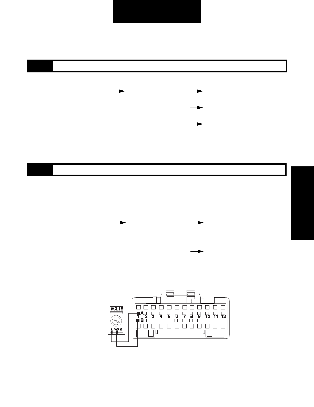
4. Measure voltage
between shift lever
24-way connector
pins A1 and B1.
If voltage is within 1 volt
of battery voltage
Replace shift lever. Go to Step A.
Fault Isolation Procedures
If voltage is outside of
range
Repair or replace tower harness.
Go to Step A.
2-4
Page 22

Fault Isolation Procedures
Power-Up Sequence Pretest , continued
Step C Procedure Condition Action
1. Key on.
2. Connect hand-held diagnostic
tool to transmission diagnostic
port.
3. Select monitor data and view
"TRANS_RNG_SEL".
4. Disconnect shift lever 24-way
5. Place a jumper
between shift lever
24-way connector
pins:
• A1 and B3
• B1 and B4
If TRANS_RNG_SEL
reads "HI"
If hand-held diagnostic
tool does not read
TRANS_RNG_SEL "HI"
Go to Step D.
Go to Step E.
2-5
Page 23

Fault Isolation Procedures
Power-Up Sequence Pretest , continued
Step D Procedure Condition Action
1. Key on.
2. Remove jumpers.
3. Place a jumper
between shift lever
24-way connector
pins:
• B1 and B3
• A1 and B4
If TRANS_RNG_SEL
reads "LO"
If hand-held diagnostic
tool does not read
TRANS_RNG_SEL "LO"
Replace shift lever. Go to Step A.
Go to Step E.
Fault Isolation Procedures
2-6
Page 24

Fault Isolation Procedures
Power-Up Sequence Pretest , continued
Step V Procedure Condition Action
1. Disconnect system manager 32way connector.
2. Measure resistance
between system
manager 32-way
connector pins and shift lever
24-way connector pins:
• 32-way D8 and 24-way B8
• 32-way C8 and 24-way B7
• 32-way D9 and 24-way B6
• 32-way C9 and 24-way B5
• 32-way C13 and 24-way B4
• 32-way D13 and 24-way B3
If resistance for each
measurement is 0 to .3
ohms
If any measurement is
outside of range
Replace system manager ECU. Go
to Step A.
Repair or replace tower har ness as
required. Go to Step A.
2-7
Page 25

Fault Isolation Procedures
Power-Up Sequence Pretest , continued
Fault Isolation Procedures
This page left blank intentionally.
2-8
Page 26

Air Pretest
r
Fault Isolation Procedures
Overview
The pretest does not relate to any specific fault code, but must
be completed before performing Fault Code Isolation Table
procedures. The pretest verifies that the basic air input is OK
before testing individual system functions.
Detection
There is no detection process specifically for the basic air supply. However, failures of this type are generally detected by the
transmission or driver as some other type of fault code or
symptom.
Fallback
There is no fallback mode for air pretest, however, it may effect
other systems.
Required Tools
• Basic Hand Tools
• 0-100 PSI Air Pressure Gauge
• Troubleshooting Guide
Possible Causes
This pretest can be used for any of the following:
• Low Air Pressure
• Contaminated Air
• Air Filter / Regulator
2-9
Air filter/regulato
Page 27

Fault Isolation Procedures
Air Pretest
Step A Procedure Condition Action
1. Key off.
2. Install a 0 to 100 PSI air gauge
in the requlated test port of the
air filter/regulator.
3. Start engine and
allow air pressure to
build to governor cutoff.
If air pressure cuts off at
90 to 120 PSI
If air pressure is outside
of range
Go to Step B.
Repair vehicle air system as
required. Repeat this step.
Fault Isolation Procedures
Step B Procedure Condition Action
1. Key off.
2. Monitor air pressure. If vehicle maintains air
pressure
If vehicle loses air
pressure
Go to Step C.
Repair vehicle air system as
required. Repeat this step.
2-10
Page 28

Fault Isolation Procedures
Air Pretest, continued
Step C Procedure Condition Action
1. Read air pressure
gauge installed at the
requlated port.
If air pressure is 55 to 65
PSI
If air pressure is outside
of range
Test Complete.
Repair vehicle air system as
required. Repeat this Step V.
Step V Procedure Condition Action
1. Remove air supply
line to the air filter/
regulator and check
air flow.
If air flows from the
supply line
If air does not flow from
the supply line
Replace air filter/regulator. Go to
Step C.
Repair vehicle air supply to the
regulator. Go to Step C.
2-11
Page 29

Air Pretest, continued
Fault Isolation Procedures
Fault Isolation Procedures
This page left blank intentionally.
2-12
Page 30

Component Code: 11
(SID 254, FMI 2,12)
System Manager
Fault Isolation Procedures
Overview
This fault code indicates an internal failure of the System Manager ECU.
Detection
The System Manager checks the program memory every time
the key is turned on. If the System Manager ECU is able to detect a failure within its own memory, it sets this fault code.
Fallback
This fault causes an In Place fallback while moving and a selfcheck failure if it occurs during power-up.
Required Tools
• Basic Hand Tools
• AutoSelect/AutoShift Troubleshooting Guide
Possible Causes
This fault can be caused by any of the following:
• Improper configuration software
• Fault System Manager ECU
2-13
Page 31

Fault Isolation Procedures
Code 11 (SID 254, FMI 2,12), System Controller Test
Step A Procedure Condition Action
1. Key on.
2. Retrieve code (see
page 1-4)
If code 11 is active Replace System Manager.
If code 11 is inactive Test complete.
Fault Isolation Procedures
2-14
Page 32

Component Code: 12
(SID 233, FMI 12)
Transmission ECU
Fault Isolation Procedures
Overview
The code indicates an internal failure of the Transmission ECU.
Detection
The Transmission ECU checks the program memory every
time the key is turned on. If the transmission is able to detect
a failure within its own memory, it sets this fault code.
Fallback
This fault causes an In Place fallback while moving and a failure during system initialization.
Required Tools
• Basic Hand Tools
• AutoSelect/AutoShift Troubleshooting Guide
Possible Causes
This fault can be caused by any of the following:
• Improper configuration software
• Faulty Transmission ECU
2-15
Page 33

Fault Isolation Procedures
Code 12 (SID 233, FMI 12),Transmission ECU Test
Step A Procedure Condition Action
1. Key on.
2. Retrieve codes (see
page 1-4)
If code 12 is active Replace Transmission ECU.
If code 12 is inactive Test complete.
Fault Isolation Procedures
2-16
Page 34

Component Code: 13
(SID 236, FMI 4,5)
Power Connect Relay Coil
Fault Isolation Procedures
Overview
This code indicates an electrical failure of the relay used to distribute power throughout the transmission system.
Detection
The System Manager checks the integrity of the Power Connect Relay Coil. If it detects a short to ground or open it sets a
fault.
Fallback
This fault causes and In Place fallback while moving and a failure during system initialization.
Required Tools
• Basic Hand Tools
• Digital Volt/Ohm Meter
• AutoSelect/AutoShift Troubleshooting Guide
Possible Causes
This fault can be caused by any of the following:
• System manager ECU
• Tower harness
• Power connect relay
2-17
Page 35

Fault Isolation Procedures
Code 13 (SID 236, FMI 4,5), Power Connect Relay Coil Test
Step A Procedure Condition Action
1. Key off.
2. Disconnect system manager 24way connector.
3. Measure resistance
between system
manager 24-way
connector pins A6 and B4.
If resistance is 40 to 90
ohms
If resistance is outside of
range
Replace system manager ECU
(Only if Fault Code is Active). Go
to Step V.
Go to Step B.
Fault Isolation Procedures
2-18
Page 36

Fault Isolation Procedures
M
Code 13 (SID 236, FMI 4,5), Power Connect Relay Coil Test, continued
Step B Procedure Condition Action
1. Remove power connect relay
connector from tower harness.
2. Measure resistance between
power connect relay pins 85 and
86.
If resistance is 40 to 90 ohms Repair or replace tower harness.
Go to Step V.
If resistance is outside of range Replace power connect relay. Go
to Step V.
Step V Procedure Condition Action
1. Key off.
2. Reconnect all connectors.
3. Key on.
4. Clear Fault Codes (see page 1-4)
5. Use Driving Technique (see
page 1-6) to attempt to reset the
code.
6. Retrieve Fault Codes (see
page 1-4)
2-19
If no codes Test complete.
If code 13 appears Return to Step A to find error in
testing.
If code other than 13 appears Go to Fault Code Isolation
Procedure Index (see page 1-10).
Page 37

Fault Isolation Procedures
Code 13 (SID 236, FMI 4,5), Power Connect Relay Coil Test, continued
Fault Isolation Procedures
This page left blank intentionally.
2-20
Page 38

Component Code: 14
(SID 18, FMI 12)
Shift Lever
Fault Isolation Procedures
Overview
This code indicates an internal failure of the shift lever.
Detection
Starting at key-on and throughout operation, the System Manager constantly measures the feedback from the Shift Lever
circuit. If the feedback is out of range, the fault is set. This type
of failure represents a short to battery, short to ground, or
open circuit.
Fallback
This fault causes a downshift only fallback.
Required Tools
• Basic Hand Tools
• Digital Volt/Ohm Meter
• AutoSelect/AutoShift Troubleshooting Guide
Possible Causes
This fault can be caused by any of the following:
• Malfunctioning shift lever
• System Manager
• OEM harness
2-21
Page 39

Fault Isolation Procedures
Code 14 (SID 18, FMI 12), Shift Lever Test
Step A Procedure Condition Action
1. Key off.
2. Disconnect shift lever 24-way
connector.
3. Key on.
4. Measure voltage across shift
lever 24-way connector pins A1
and B1.
If voltage is within 1 volt of battery
voltage
If voltage is outside of range Repair ignition supply to shift lever.
Replace shift lever (Only if Fault
Code is Active). Go to Step V.
Go to Step V.
Fault Isolation Procedures
2-22
Page 40

Fault Isolation Procedures
Code 14 (SID 18, FMI 12), Shift Lever Test, continued
Step V Procedure Condition Action
1. Key off.
2. Reconnect all connectors.
3. Key on.
4. Clear Fault Codes (see page 1-4)
5. Use Driving Technique (see
page 1-6) to attempt to reset the
code.
6. Retrieve Fault Codes (see
page 1-4)
If no codes Test complete.
If code 14 appears Return to Step A to find error in
testing.
If code other than 14 appears Go to Fault Code Isolation
Procedure Index (see page 1-10).
2-23
Page 41

Fault Isolation Procedures
Code 14 (SID 18, FMI 12), Shift Lever Test, continued
Fault Isolation Procedures
This page left blank intentionally.
2-24
Page 42

Component Code: 15
(SID 57, FMI 2)
Shift Lever Data Link
Fault Isolation Procedures
Overview
This code indicates that the system manager ECU and the shift
lever are unable to communicate.
Detection
The System Manager constantly monitors communication
with the Shift Lever and sets a fault if communication drops
out.
Fallback
There is no Fallback Mode for this fault.
Required Tools
• Basic Hand Tools
• Hand-Held Diagnostic Tool
• Digital Volt/Ohm Meter
• AutoSelect/AutoShift Troubleshooting Guide
Possible Causes
This fault can be caused by any of the following:
• Damaged shift lever data link
• Malfunctioning shift lever
• Malfunctioning system manager ECU
2-25
Page 43

Fault Isolation Procedures
Code 15 (SID 57, FMI 2), Shift Lever Data Link Test
Step A Procedure Condition Action
1. Key on.
2. Retrieve Fault Codes (see
page 1-4)
If code 15 is active Replace Eaton supplied shift tower
containing system manager and
shift lever. If vehicle has the
system manager ECU mounted in a
separate location from the shift
lever, go to Step B.
If code 15 is inactive Test complete.
Step B Procedure Condition Action
1. Key off.
2. Connect hand-held diagnostic
tool to transmission diagnostic
port.
3. Select monitor data view
"TRANS_RNG_SEL".
Disconnect shift lever 24-way
connector.
Place a jumper between shift lever
24-way connector pins:
• A1 and B3
• B1 and B4
If TRANS_RNG_SEL reads "HI" Go to Step C.
Fault Isolation Procedures
If hand-held diagnostic tool does
not read TRANS_RNG_SEL "HI"
Go to Step D.
2-26
Page 44

Fault Isolation Procedures
Code 15 (SID 57, FMI 2), Shift Lever Data Link Test, continued
Step C Procedure Condition Action
1. Remove jumpers.
2. Place a jumper between shift
lever 24-way connector pins:
• B1 and B3
• A1 and B4
If TRANS_RNG_SEL reads "LO" Replace shift lever. Go to Step V.
If hand-held diagnostic tool does
not read TRANS_RNG_SEL "LO"
Go to Step D.
2-27
Page 45

Fault Isolation Procedures
Code 15 (SID 57, FMI 2), Shift Lever Data Link Test, continued
Step D Procedure Condition Action
1. Disconnect system manager 32way connector.
2. Measure resistance between
system manager 32-way
connector pins and shift lever
24-way connector pins:
• 32-way D8 and 24-way B8
• 32-way C8 and 24-way B7
• 32-way D9 and 24-way B6
• 32-way C9 and 24-way B5
• 32-way C13 and 24-way B4
• 32-way D13 and 24-way B3
If resistance for each measurement
is 0 to .3 ohms
If any measurement is outside of
range
Replace system manger ECU. Go
to Step V.
Repair or replace tower harness as
required. Go to Step V.
Fault Isolation Procedures
2-28
Page 46

Fault Isolation Procedures
Code 15 (SID 57, FMI 2), Shift Lever Data Link Test, continued
Step V Procedure Condition Action
1. Key off.
2. Reconnect all connectors.
3. Key on.
4. Clear Fault Codes. (see page 1-
4)
5. Use Driving Technique (see
page 1-6) to attempt to reset the
code.
6. Retrieve Fault
Codes(see page 1-4)
If no codes Test complete.
If code 15 appears Return to Step A to find error in
testing.
If code other than 15
appears
Go to Fault Code Isolation
Procedure Index. (see page 1-10)
2-29
Page 47

Fault Isolation Procedures
Code 15 (SID 57, FMI 2), Shift Lever Data Link Test, continued
Fault Isolation Procedures
This page left blank intentionally.
2-30
Page 48

Component Code: 16
(SID 248, FMI 2)
Eaton Proprietary Link (EPL)
Fault Isolation Procedures
Overview
This code indicates that the system manager ECU and the
transmission ECU are unable to communicate.
Detection
Starting at key-on and throughout operation, the System Manager constantly monitors the communication with the Transmission ECU. If a communication fault occurs for more than
five seconds, fault code 16 is set.
Fallback
This fault causes an In Place fallback while moving and a failure during system initialization.
Required Tools
• Basic Hand Tools
• Hand-Held Diagnostic Tool
• Digital Volt/Ohm Meter
• AutoSelect/AutoShift Troubleshooting Guide
• Data Link Tester
Possible Causes
This fault can be caused by any of the following:
• Damaged transmission interface harness
• Damaged transmission harness
• Damaged tower or OEM harness
• Malfunctioning transmission ECU
• Malfunctioning system manager ECU
• Powers and Grounds
• Damaged PIM
2-31
Page 49

Fault Isolation Procedures
Code 16 (SID 248, FMI 2), Eaton Proprietary Link (EPL) Test
Step A Procedure Condition Action
1. Key off.
2. Inspect starter/
battery,inline fuse
holder and PIM
connections for integrity.
If okay Go to Step B.
If corroded or loose Repair wiring or battery
connections. Go to Step V.
Fault Isolation Procedures
2-32
Page 50

Fault Isolation Procedures
CAUTION
CAUTION
Code 16 (SID 248, FMI 2), Eaton Proprietary Link (EPL) Test, continued
Step B Procedure Condition Action
1. Key off.
2. Insert 15-amp fuse
into Motor Supply 2way connector.
If fuse blows immediately
Disconnect negative battery cable
before reconnecting motor supply
2-way connector. Go to Step C.
If fuse does not blow
immediately
Disconnect the battery cable
before reconnecting the motor
supply 2-way connector. Failure to
disconnect the battery negative
cable can cause the failure of the
power interface module. Replace
power interface module. Go to
Step V.
2-33
Page 51

Fault Isolation Procedures
Code 16 (SID 248, FMI 2), Eaton Proprietary Link (EPL) Test, continued
Step C Procedure Condition Action
1. Key off.
2. Disconnect transmission ECU
24-way connector.
3. Place a jumper between
transmission ECU 24-way
connector pins 2 and 14. The
procedure is providing ground
to the system manager ecu
during the test.
4. Key on.
5. Measure voltage
across transmission
ECU 24-way
connector pins 1 and 14. This
procedure is checking for
correct voltage from the power
connect relay to the
transmission controller.
If voltage is within 1 volt
of battery voltage
If voltage is outside of
range
Go to Step E.
Fault Isolation Procedures
Go to Step D.
2-34
Page 52

Fault Isolation Procedures
Code 16 (SID 248, FMI 2), Eaton Proprietary Link (EPL) Test, continued
Step D Procedure Condition Action
1. Remove jumper.
2. Disconnect transmission
harness from transmission
interface harness.
3. Disconnect power interface
module from transmission
harness.
4. Measure resistance between
transmission ECU 24-way
connector pin 14 and power
interface module connector pin
A on transmission harness. This
procedure is checking the
resistance of the ground wire
supplied by the pim to the
transmission ecu.
5. Measure resistance
between transmission
harness 6-way
connector pin D and
transmission ECU 24-way
connector pin 1. This procedure
is checking resistance of the
power connect relay feed from
the 6-way connector to the
transmission ecu.
If both measurements
are 0 to .3 ohms
If either measurement is
outside of range
Repair or replace vehicle
interface harness or tower
harness. Go to Step V.
Repair or replace transmission
harness. Go to Step V.
2-35
Page 53

Fault Isolation Procedures
Code 16 (SID 248, FMI 2), Eaton Proprietary Link (EPL) Test, continued
Step E Procedure Condition Action
1. Reconnect transmission ECU
24-way connector.
2. Key off. Allow transmission to
power down.
3. Disconnect system manager 32way connector.
4. Connect data link tester to
system manager 32-way
connector pins C2 and D1.
5. Key on.
6. Start EPL
Communication Test.
If LED is solid or flashing Replace system manager ECU
(Only if Fault Code is Active). Go
to Step V.
If LED is off Go to Step F.
Fault Isolation Procedures
2-36
Page 54

Fault Isolation Procedures
Code 16 (SID 248, FMI 2), Eaton Proprietary Link (EPL) Test, continued
Step F Procedure Condition Action
1. Key off. Allow transmission to
power down.
2. Disconnect transmission ECU
32-way connector.
3. Remove EPL tester from system
manager 32-way connector.
Measure resistance
between system
manager 32-way
connector pins C2 and D1 and
from each pin to ground.
If resistance for each
measurement is more
than 10K ohms or open
circuit (OL)
If resistance of any
measurement is less than
10K ohms
Go to Step G.
Go to Step H.
2-37
Page 55

Fault Isolation Procedures
Code 16 (SID 248, FMI 2), Eaton Proprietary Link (EPL) Test, continued
Step G Procedure Condition Action
1. Place a jumper across
transmission ECU 32-way
connector pins 29 and 30.
2. Measure resistance
between system
manager 32-way
connector pins C2 and D1.
If resistance is 0 to .3
ohms
If resistance is outside of
range
Replace transmission ECU. Go to
Step V.
Go to Step H.
Fault Isolation Procedures
2-38
Page 56

Fault Isolation Procedures
Code 16 (SID 248, FMI 2), Eaton Proprietary Link (EPL) Test, continued
Step H Procedure Condition Action
1. Reconnect system manager 32way connector.
2. Disconnect transmission
harness 3-way connector from
transmission interface harness.
3. Remove any jumper wires
currently in place.
4. Measure resistance between
transmission harness 3-way
connector pins A and B and
from each pin to ground.
Note: Depending on
which
connector you
have, refer to either the
old style or the new style
connector illustration.
If resistance for each
measurement is more
than 10K ohms or open
circuit (OL)
If resistance of any
measurement is less than
10K ohms
Go to Step H.
Repair or replace transmission
harness.Go to Step V.
2-39
Page 57

Fault Isolation Procedures
Code 16 (SID 248, FMI 2), Eaton Proprietary Link (EPL) Test, continued
Step I Procedure Condition Action
1. Measure resistance between
transmission ECU 32-way
connector pin 29 and
transmission harness 3-way
connector pin A.
Note: Depending on which
connector you have, refer to
either the old style or the new
style connector illustration.
2. Measure resistance
between
transmission ECU 32way connector pin 30 and
transmission harness 3-way
connector pin B.
If both measurements are
0 to .3 ohms
If either measurement is
outside of range
Repair OEM wiring from system
manager ECU to transmission. Go
to Step V.
Fault Isolation Procedures
Repair or replace transmission
harness.Go to Step V.
2-40
Page 58

Fault Isolation Procedures
Code 16 (SID 248, FMI 2), Eaton Proprietary Link (EPL) Test, continued
Step V Procedure Condition Action
1. Key off.
2. Reconnect all connectors.
3. Key on.
4. Clear Fault Codes (see page 1-4)
5. Use Driving Technique (see
page 1-6) to attempt to reset the
code.
6. Retrieve Fault
Codes(see page 1-4)
If no codes Test complete.
If code 16 appears Return to Step A. to find error in
testing.
If code other than 16
appears
Go to Fault Code Isolation
Procedures Index.(see page 1-10)
2-41
Page 59

Fault Isolation Procedures
Code 16 (SID 248, FMI 2), Eaton Proprietary Link (EPL) Test, continued
Fault Isolation Procedures
This page left blank intentionally.
2-42
Page 60

Component Code: 17
(SID 237, FMI 4)
Start Enable Relay Coil
Fault Isolation Procedures
Overview
This fault code indicates an electrical failure of the relay that allows the engine to start after start-up conditions are met.
Detection
Starting at key-on and throughout operation, the System Manager constantly measures the circuit. A failure mode of short
to battery, short to ground, or open circuit is detected.
Fallback
The start enable relay has no fallback, however, if the failure occurred before the engine was started, it is possible the engine
will not start.
Required Tools
• Basic Hand Tools
• Digital Volt/Ohm Meter
• AutoSelect/AutoShift Troubleshooting Guide
Possible Causes
This fault can be caused by any of the following:
• Relay coil open or shorted
• Damaged tower or OEM harness
• Malfunctioning system manager ECU
2-43
Page 61

Fault Isolation Procedures
Code 17 (SID 237, FMI 4), Start Enable Relay Coil Test
Step A Procedure Condition Action
1. Key off.
2. Disconnect system manager.
3. Measure resistance
between system
manager 24-way
connector pin A1 and ground.
If resistance is 40 to 120
ohms
If resistance is outside of
range
Replace system manager ECU
(Only if Fault Code is Active). Go
to Step V.
Go to Step B.
Fault Isolation Procedures
2-44
Page 62

Fault Isolation Procedures
Code 17 (SID 237, FMI 4), Start Enable Relay Coil Test, continued
Step B Procedure Condition Action
1. Remove start enable relay from
OEM dash harness.
2. Measure resistance
between start enable
relay pins 85 and 86.
If resistance is 40 to 120
ohms
If resistance is outside of
range
Repair OEM wiring from system
manager ECU to start enable relay.
Go to Step V.
Replace start enable relay. Go to
Step V.
M
Step V Procedure Condition Action
1. Key off.
2. Reconnect all connectors.
3. Key on.
4. Clear Fault Codes (see page 1-4)
5. Use Driving Technique (see
page 1-6) to attempt to reset the
code.
6. Retrieve Fault Codes
(see page 1-4).
2-45
If no codes Test complete
If code 17 appears Return to Step A to find error in
testing.
If code other than 17
appears
Go to Fault Code Isolation
Procedure Index. (see page 1-10)
Page 63

Fault Isolation Procedures
Code 17 (SID 237, FMI 4), Start Enable Relay Coil Test, continued
Fault Isolation Procedures
This page left blank intentionally.
2-46
Page 64

Component Code: 31
(PID 62, FMI 3,4)
Engine Brake Relay Coil
Fault Isolation Procedures
Overview
This code indicates an electrical failure of the relay used to inhibit the engine brake during shifts.
Detection
Starting at key-on and throughout operation, the System Manager constantly measures this circuit. A failure mode of a short
to battery, short to ground, or open circuit is detected.
Fallback
There is no fallback mode with this fault.
Required Tools
• Basic Hand Tools
• Digital Volt/Ohm Meter
• AutoSelect/AutoShift Troubleshooting Guide
Possible Causes
This fault can be caused by any of the following:
• Relay coil open or shorted
• Damaged tower or OEM harness
• Malfunctioning system manager ECU
2-47
Page 65

Fault Isolation Procedures
Code 31 (PID 62, FMI 3,4), Engine Brake Relay Coil Test
Step A Procedure Condition Action
1. Key off.
2. Disconnect system manager 24way connector.
3. Measure resistance
between system
manager 24-way
connector pin A3 and ground.
If resistance is 40 to 90
ohms
If resistance is outside of
range
Replace system manager ECU
(Only if Fault Code is Active). Go
to Step V.
Go to Step B.
Fault Isolation Procedures
2-48
Page 66

Fault Isolation Procedures
Code 31 (PID 62, FMI 3,4), Engine Brake Relay Coil Test, continued
Step B Procedure Condition Action
1. Remove engine brake inhibit
relay from OEM dash harness.
2. Measure resistance
between engine brake
inhibit relay pins 85
and 86.
If resistance is 40 to 90
ohms
If resistance is outside of
range
Repair OEM wiring from system
manager ECU to engine brake
inhibit relay. Go to Step V.
Replace engine brake inhibit relay.
Go to Step V.
M
2-49
Page 67

Fault Isolation Procedures
Code 31 (PID 62, FMI 3,4), Engine Brake Relay Coil Test, continued
Step V Procedure Condition Action
1. Key off.
2. Reconnect all connectors.
3. Key on.
4. Clear Fault Codes(see page 1-4)
5. Use Driving Technique(see
page 1-6) to attempt to reset the
code.
6. Retrieve Fault
Codes(see page 1-4)
If no codes Test complete.
If code 31 appears Return to Step A to find error in
testing.
If code other than 31
appears
Go to Fault Code Isolation
Procedure Index.(see page 1-10)
Fault Isolation Procedures
2-50
Page 68

Component Code: 33
(PID 168, FMI 4)
Battery Voltage Supply
Fault Isolation Procedures
Overview
This code indicates the system manager has detected that the
battery power supply is low.
Detection
The fault is detected immediately after power-up. This fault
causes the service lamp to flash, but cannot be retrieved via
key clicks (because turning the ignition key off at this point results in an immediate shutdown).
Fallback
This fault causes an In Place fallback.
Required Tools
• Basic Hand Tools
• Digital Volt/Ohm Meter
• AutoSelect/AutoShift Troubleshooting Guide
•
Possible Causes
This fault can be caused by any of the following:
• Battery bus fuse/circuit breaker is open
• Low batteries
• Damaged tower or OEM harness
• Damaged transmission harness
• Malfunctioning power connect relay
• Malfunctioning system manager ECU
2-51
Page 69

Fault Isolation Procedures
Code 33 (PID 168, FMI 4), Battery Voltage Supply Test
Step A Procedure Condition Action
1. Key off.
2. Inspect starter/battery,
inline fuse holder and
PIM connections for
integrity.
If okay Go to Step B.
If corroded or loose Repair wiring or battery
connections. Go to Step V.
Fault Isolation Procedures
2-52
Page 70

Fault Isolation Procedures
CAUTION
CAUTION
Code 33 (PID 168, FMI 4), Battery Voltage Supply Test, continued
Step B Procedure Condition Action
1. Key off.
2. Insert 15-amp fuse
into Motor Supply 2way connector.
If fuse blows immediately
Disconnect the negative battery
cable before reconnecting the
motor supply 2-way connector.
Failure to disconnect the battery
negative cable can cause the
failure of the power interface
module.Go to Step C.
If fuse does not blow
immediately
Disconnect the negative battery
cable before reconnecting the
motor supply 2-way connector.
Failure to disconnect the battery
negative cable can cause the
failure of the power interface
module. Replace power interface
module. Go to Step V.
2-53
Page 71

Fault Isolation Procedures
Code 33 (PID 168, FMI 4), Battery Voltage Supply Test, continued
Step C Procedure Condition Action
1. Key on.
2. Retrieve Fault Codes
(see page 1-4)
If code 33 is active Perform Electrical System Test (see
page 3-1).
If code 33 is inactive Test complete.
Fault Isolation Procedures
2-54
Page 72

System Code: 35
(SID 231, FMI 2,7)
Engine Control Failure
Fault Isolation Procedures
Overview
This code indicates the AutoShift failed to receive information
from the engine or the engine failed to properly respond to
throttle control during a shift as commanded by the engine J1939 data link.
Detection
75 seconds after key-on and throughout the operation, the
System Manager constantly monitors the communication with
the engine ECM. If a communication fault occurs for more than
five seconds, fault code 35 is set.
Fallback
If the fault occurs while moving, it causes a 1-speed fallback.
Once vehicle has stopped, the starting gear and reverse can be
engaged. If the failure occurs at system initialization, it causes
an AutoSelect fallback mode.
Required Tools
• Basic Hand Tools
• Hand-Held Diagnostic Tool
• Digital Volt/Ohm Meter
• AutoSelect/AutoShift Troubleshooting Guide
• Data Link Tester
Possible Causes
This fault can be caused by any of the following:
• Faulty J-1939 data link
• Faulty vehicle interface harness or connections
• Faulty engine harness or connections
• Excessive radio interference
• Faulty engine ECM
• Faulty engine fuel pump
• Faulty system manager ECU
2-55
Page 73

Fault Isolation Procedures
Code 35 (SID 231, FMI 2,7), Engine Control Failure Test
Step A Procedure Condition Action
1. Key off.
2. Disconnect system manager 32way connector.
3. Disconnect engine ECM’s
connector which contains the J1939 data link.
4. Measure resistance
between:
• System manager
32-way connector pin C5 and
engine ECM pin # (see chart)
• System manager 32-way pin
C5 and ground
• If resistance between
pin C5 and engine ECM
pin # (see chart) is 0 to .3
ohms and
• If resistance between pin C5 and
ground is more than 10K ohms or
open circuit (OL)
If resistance is outside of
range
Go to Step B.
Fault Isolation Procedures
Repair J-1939 data link harness
between engine ECM and system
manager. Go to Step V.
2-56
Page 74

Fault Isolation Procedures
Code 35 (SID 231, FMI 2,7), Engine Control Failure Test, continued
Step B Procedure Condition Action
1. Key off.
2. Measure resistance
between:
• System manager 32way connector pin C4
and engine ECM pin # (see chart)
• System manager 32-way pin
C4 and ground
• If resistance between pin
C4 and engine ECM pin #
(see chart) is 0 to .3 ohms
and
• If resistance between pin C4 and
ground is more than 10K ohms or
open circuit (OL)
If resistance is outside of
range
• If equipped with J-1939-Lite, go
to Step D.
• If not equipped with J-1939-Lite,
go to Step C.
Repair J-1939 data link harness
between engine ECM and system
manager. Go to Step V.
2-57
Page 75

Fault Isolation Procedures
Code 35 (SID 231, FMI 2,7), Engine Control Failure Test, continued
Step C Procedure Condition Action
1. Key off.
2. Measure resistance
between system
manager 32-way
connector pin D5 and engine
ECM pin # (see chart).
If resistance between pin
D5 and engine ECM pin #
(see chart) is 0 to .3
ohms
If resistance is outside of
range
Go to Step D. (If working on a Mack
engine, go to Step E).
Repair J-1939 data link harness
between engine ECM and system
manager. Go to Step V.
Fault Isolation Procedures
2-58
Page 76

Fault Isolation Procedures
Code 35 (SID 231, FMI 2,7), Engine Control Failure Test, continued
Step D Procedure Condition Action
1. Key off.
2. Measure resistance between
system manager 32-way
connector pins C5 and C4.
Note: Make sure the
volt/ohm meter
is on the proper
scale (around
200 ohm scale).
If resistance between pin
C5 and C4 is between 50
to 70 ohms
If resistance is above 70
ohms
If resistance is less than
50 ohms
Go to Step E.
One or both of the terminating
resistors on J-1939 data link
harness are either missing or out of
range. Repair J-1939 data link
harness. Go to Step V.
Repair the J-1939 data link in
between the engine ECM and the
system manager. Go to Step V.
2-59
Page 77

Fault Isolation Procedures
Code 35 (SID 231, FMI 2,7), Engine Control Failure Test, continued
Step E Procedure Condition Action
1. Key off.
Note: Data link test is designed to
test a signal from an
individual ECU. The ECU
must be isolated from the
rest of the Data link.
2. Reconnect engine ECM
connector and system manager
32-way connector.
3. Disconnect the 3-way stub
connector, which connects the
transmission into the J-1939
data link.
4. Connect the data link tester to
the 3-way stub connector,
which connects the
transmission into the J-1939
data link.
• Red lead from data link tester
connects to the +J-1939
•Black lead from data link tester
connects to the -J-1939
Note: If vehicle does not use 3-
way stub connectors,
then do no reconnect the
engine ECM connector
and connect the data link
tester across the +/- J1939 terminals (see
chart).
5. Place the data link tester in
communication mode.
Fault Isolation Procedures
6. Key on. If LED is solid or flashing Problem exists with the engine
ECM. Repair according to
manufacturer’s recommendations.
Go to Step V.
If LED if off Replace system manager. Go to
Step V.
2-60
Page 78

Fault Isolation Procedures
Code 35 (SID 231, FMI 2,7), Engine Control Failure Test, continued
Step V Procedure Condition Action
1. Key off.
2. Key on.
3. Clear Fault Codes (see page 1-4)
4. Use Driving Technique to
attempt to reset the code (see
page 1-6)
5. Retrieve Fault Codes
(see page 1-4)
If no codes Test complete.
If code 35 appears Return to Step A to find error in
testing.
If code other than 35
appears
Go to Fault Code Isolation
Procedure Index. (see page 1-10)
2-61
Page 79

Fault Isolation Procedures
Code 35 (SID 231, FMI 2,7), Engine Control Failure Test, continued
Fault Isolation Procedures
This page left blank intentionally.
2-62
Page 80

System Code: 41
(SID 56, FMI 7)
Range Failed to Engage
Fault Isolation Procedures
Overview
This code indicates the transmission is unable to complete a
shift across the range. The range is either stuck in HI or LO, or
cannot complete engagement in HI or LO.
Detection
The transmission attempts the same range shift five consecutive times and determines the shift cannot be completed based
on the speeds across the back box.
Fallback
This fault causes a 5-speed fallback and the transmission stays
in either LO range or HI range. When the vehicle comes to a
stop, an attempt to shift into LO range is made.
Required Tools
• Basic Hand Tools
• (2) 0-100 PSI Air Pressure Gauges
• AutoSelect/AutoShift Troubleshooting Guide
Possible Causes
This fault can be caused by any of the following:
• Low air pressure
• Contaminated air supply
• Air leak
• Range solenoid stuck
• Failed range synchronizer
• Failed range actuator/cylinder/piston/yoke
2-63
Page 81

Fault Isolation Procedures
Code 41 (SID 56, FMI 7), Range Failed to Engage Test
Step A Procedure Condition Action
1. Key off.
2. Install both 0 to 100 PSI air
gauges into the range valve
diagnostic ports.
3. Start vehicle and allow air
pressure to reach governor cutoff.
4. Release clutch to register input
speed in transmission.
5. Turn off engine, but leave key in
"ON" position.
6. With the shift control,
select reverse and
back to neutral.
If LO range gauge = 55 to 65 PSI
and
If HI range gauge = 0 PSI
Note: 5 minutes is
allowed for
checking the
pressure after moving the
shift lever to neutral.
If both air gauges do not
read in range
Go to Step B.
Repair or replace range valve and
range cylinder as required. Retest.
Fault Isolation Procedures
2-64
Page 82

Fault Isolation Procedures
D
Code 41 (SID 56, FMI 7), Range Failed to Engage Test, continued
Step B Procedure Condition Action
1. Move shift lever to reverse,
press upshift button, and move
lever back to neutral.
Note: If shift lever DOES
NOT have upshift
buttons, move shift
lever to reverse and place a
jumper between service port
connector pins B and D.
Remove jumper and place
shift lever in neutral.
If HI range gauge = 55 to 65 PSI and
If LO range gauge = 0 PSI
Note: 5 minutes is
allowed for
checking the
pressure after moving the
shift lever to neutral.
If both air gauges do not
read in range
H
B
Repair or replace mechanical range
system as required. Go to Step V.
Repair or replace range valve and
range cylinder as required. Go to
Step V.
G
2-65
Page 83

Fault Isolation Procedures
Code 41 (SID 56, FMI 7), Range Failed to Engage Test, continued
Step V Procedure Condition Action
1. Disconnect gauges.
2. Reconnect all connectors.
3. Key on.
4. Clear Fault Codes (see page 1-4)
5. Use Driving Technique (see
page 1-6) to attempt to reset the
code.
6. Retrieve Fault Codes
(see page 1-4)
If no codes Test complete.
If code 41 appears Return to Step A to find error in
testing.
If code other than 41
appears
Go to Fault Code Isolation
Procedure Index. (see page 1-10)
Fault Isolation Procedures
2-66
Page 84

System Code: 42
(SID 61, FMI 7)
Splitter Failed to Engage
Fault Isolation Procedures
Overview
This code indicates the transmission is unable to complete a
shift across the splitter. The splitter is either stuck in HI or LO,
or cannot complete engagement in HI or LO.
Detection
The transmission attempts the same splitter shift five consecutive times and determines the shift cannot be completed
based on the speeds across the back box.
Fallback
This fault causes a 9-speed fallback and the transmission stays
in either LO split or HI split.
Required Tools
• Basic Hand Tools
• (2) 0-100 PSI Air Pressure Gauges
• AutoSelect/AutoShift Troubleshooting Guide
Possible Causes
This fault can be caused by any of the following:
• Low air pressure
• Contaminated air supply
• Air leak
• Splitter solenoid stuck
• Failed splitter actuator/cylinder/piston/yoke
2-67
Page 85

Fault Isolation Procedures
Code 42 (SID 6,1, FMI 7), Splitter Failed to Engage Test
Step A Procedure Condition Action
1. Key off.
2. Install both 0 to 100 PSI air
gauges into the splitter valve
diagnostic ports.
3. Start vehicle and allow air
pressure to reach governor cutoff.
4. Release clutch to register input
speed in transmission.
5. Turn off engine, but leave key in
"ON" position.
6. With the shift control,
select reverse and
back to neutral.
If HI split gauge = 55 to 65 PSI and
If LO split gauge = 0 PSI
Note: 5 minutes is
allowed for
checking the
pressure after moving the
shift lever to neutral.
If both gauges do not
read in range
Go to Step B.
Repair or replace splitter valve
and splitter cylinder cover as
required. Repeat this step.
Step B Procedure Condition Action
1. Key on.
2. With shift control
select reverse, press
upshift button and
select neutral.
If LO split gauge = 55 to
65 and
If HI split gauge = 0 PSI
If both gauges do not
read in range
Repair or replace mechanical
splitter system as required. Go to
Step V.
Repair or replace splitter valve
and splitter cylinder as required.
Go to Step V.
Fault Isolation Procedures
2-68
Page 86

Fault Isolation Procedures
Code 42 (SID 6,1, FMI 7), Splitter Failed to Engage Test, continued
Step V Procedure Condition Action
1. Disconnect gauges.
2. Reconnect all connectors.
3. Key on.
4. Clear Fault Codes (see page 1-4)
5. Use Driving Technique (see
page 1-6) to attempt to reset the
code.
6. Retrieve Fault Codes
(see page 1-4)
If no codes Test complete.
If code 42 appears Return to Step A to find error in
testing.
If code other than 42
appears
Go to Fault Code Isolation
Procedure Index. (see page 1-10)
2-69
Page 87

Fault Isolation Procedures
Code 42 (SID 6,1, FMI 7), Splitter Failed to Engage Test, continued
Fault Isolation Procedures
This page left blank intentionally.
2-70
Page 88

Component Code: 43
(SID 35,36, FMI 3,4,5)
Range Solenoid Valve
Fault Isolation Procedures
Overview
This code indicates an electrical failure of the solenoids that
control the pneumatic range valve.
Detection
Starting at key-on and throughout operation, the Transmission
Controller constantly measures this circuit. A failure mode of
short to battery, short to ground, or open circuit is detected.
Fallback
This fault causes a 5-speed fallback and the transmission stays
in either LO range or HI range. When the vehicle comes to a
stop, an attempt to shift into LO range is made.
Required Tools
• Basic Hand Tools
• Digital Volt/Ohm Meter
• AutoSelect/AutoShift Troubleshooting Guide
Possible Causes
This fault can be caused by any of the following:
• Range solenoid coil open or shorted
• Damaged transmission harness
• Malfunctioning transmission ECU
2-71
Page 89

Fault Isolation Procedures
Code 43 (SID 35,36, FMI 3,4,5), Range Solenoid Valve Test
Step A Procedure Condition Action
1. Key off.
2. Disconnect transmission ECU
24-way connector.
3. Measure resistance
between
transmission ECU 24way connector pins:
• 7 and 8
• 8 and 9
If resistance is 9 to 16
ohms
If resistance is outside of
range
Go to Step B.
Go to Step C.
Fault Isolation Procedures
2-72
Page 90

Fault Isolation Procedures
Code 43 (SID 35,36, FMI 3,4,5), Range Solenoid Valve Test, continued
Step B Procedure Condition Action
1. Measure resistance
between transmission
ECU 24-way
connector pin 8 and ground.
If resistance is more than
10K ohms or open circuit
(OL
If resistance is less than
10K ohms
Replace transmission ECU (Only if
Fault Code is Active). Go to Step
V.
Go to Step C.
2-73
Page 91

Fault Isolation Procedures
Code 43 (SID 35,36, FMI 3,4,5), Range Solenoid Valve Test, continued
Step C Procedure Condition Action
1. Disconnect transmission
harness from range valve.
2. Measure resistance
between range valve
pins:
• A and C
• B and C
If resistance is 9 to 16
ohms
If resistance is outside of
range
OHMS
Go to Step D.
Replace range valve. Go to Step
V.
Fault Isolation Procedures
OHMS
2-74
Page 92

Fault Isolation Procedures
OHMS
Code 43 (SID 35,36, FMI 3,4,5), Range Solenoid Valve Test, continued
Step D Procedure Condition Action
1. Measure resistance
between range valve
pin C and ground.
If resistance is more than
10K ohms or open circuit
(OL)
If resistance is less than
10K ohms
Repair or replace transmission
harness. Go to Step V.
Replace range valve. Go to Step
V.
Step V Procedure Condition Action
1. Key off.
2. Reconnect all connectors.
3. Key on.
4. Clear Fault Codes (see page 1-4)
5. Use Driving Technique (see
page 1-6) to attempt to reset the
code.
6. Retrieve Fault Codes
(see page 1-4)
If no codes Test complete.
If code 43 appears Return to Step A to find error in
testing.
If code other than 43
appears
Go to Fault Code Isolation
Procedure Index. (see page 1-10)
2-75
Page 93

Fault Isolation Procedures
Code 43 (SID 35,36, FMI 3,4,5), Range Solenoid Valve Test, continued
Fault Isolation Procedures
This page left blank intentionally.
2-76
Page 94

Component Code: 44
(PID 54, FMI 3,4,5)
Interia Brake Solenoid Coil
Fault Isolation Procedures
Overview
This code indicates an electrical problem in the interia brake.
Detection
Starting at key-on and throughout operation, the Transmission
Controller constantly measures this circuit. A failure mode of a
short to battery, short to ground, or open circuit is detected.
Fallback
There is no fallback associated with this failure. However, it
may be difficult to perform an initial engagement due to a poorly adjusted clutch. Also, hill shifting performance may be reduced.
Required Tools
• Basic Hand Tools
• Digital Volt/Ohm Meter
• AutoSelect/AutoShift Troubleshooting Guide
Possible Causes
This fault can be caused by any of the following:
• Relay coil open or shorted
• Damaged transmission harness
• Malfunctioning transmission ECU
2-77
Page 95

Fault Isolation Procedures
Code 44 (PID 54, FMI 3,4,5), Interia Brake Solenoid Coil Test
Step A Procedure Condition Action
1. Key off.
2. Disconnect 24-way
transmission ECU connector.
3. Measure resistance
between 24-way
transmission ECU
connector pins 3 and 4.
If resistance is 13 to 18
ohms
If resistance is outside of
range
Go to Step B.
Go to Step C.
Fault Isolation Procedures
2-78
Page 96

Fault Isolation Procedures
Code 44 (PID 54, FMI 3,4,5), Interia Brake Solenoid Coil Test, continued
Step B Procedure Condition Action
1. Measure resistance
between 24-way
transmission ECU
connector pin 3 and ground.
If resistance is more than
10K ohms or open circuit
(OL)
If resistance is less than
10K ohms
Replace transmission ECU (Only if
Fault Code is Active). Go to Step
V.
Go to Step C.
2-79
Page 97

Fault Isolation Procedures
Code 44 (PID 54, FMI 3,4,5), Interia Brake Solenoid Coil Test, continued
Step C Procedure Condition Action
1. Disconnect transmission
harness from interia brake
solenoid coil.
2. Measure resistance
between inertia brake
solenoid coil pins A
and B.
If resistance is 13 to 18
ohms
If resistance is outside of
range
Go to Step D.
Replace inertia brake solenoid.
Go to Step V.
M
Fault Isolation Procedures
2-80
Page 98

Fault Isolation Procedures
M
N
Code 44 (PID 54, FMI 3,4,5), Interia Brake Solenoid Coil Test, continued
Step D Procedure Condition Action
1. Measure resistance
between interia brake
solenoid coil pin A
and ground.
If resistance is more than
10K ohms or open circuit
(OL)
If resistance is less than
10K ohms
Repair or replace transmission
harness. Go to Step V.
Replace inertia brake solenoid.
Go to Step V.
Step V Procedure Condition Action
1. Key off.
2. Reconnect all connectors.
3. Key on.
4. Clear Fault Codes (see page 1-4)
5. Use Driving Technique (see
page 1-6) to attempt to reset the
code.
6. Retrieve Fault Codes
(see page 1-4)
If no codes Test complete.
If code 44 appears Return to Step A to find error in
testing.
If code other than 44
appears
Go to Fault Code Isolation
Procedure Index. (see page 1-10)
2-81
Page 99

Fault Isolation Procedures
Code 44 (PID 54, FMI 3,4,5), Interia Brake Solenoid Coil Test, continued
Fault Isolation Procedures
This page left blank intentionally.
2-82
Page 100

Fault Isolation Procedures
Component Code: 46
(SID 37,38, FMI 4,5)
Splitter Solenoid Valve
Overview
This code indicates an electrical failure of the solenoids
that control the splitter.
Detection
Required Tools
• Basic Hand Tools
• Digital Volt/Ohm Meter
• AutoSelect/AutoShift Troubleshooting Guide
Starting at key-on and throughout operation, the Transmission Controller constantly measures this circuit. Depending on the reading, a failure mode of short to battery,
short to ground, or open circuit is detected.
Fallback
This fault causes a 9-speed fallback and the transmission
stays in either LO split or HI split.
Possible Causes
This fault can be caused by any of the following:
• Solenoid coil open or shorted
• Damaged transmission harness
• Malfunctioning transmission ECU
2-83
 Loading...