

Page 1

Service Manual
Fuller Medium Heavy Transmissions
TRSM0202
October 2007
Page 2

For parts or service call us
Pro Gear & Transmission, Inc.
1 (877) 776-4600
(407) 872-1901
parts@eprogear.com
906 W. Gore St.
Orlando, FL 32805
Page 3

Page 4
Service
Manual
·Operation
•
Lubrication
·Maintenance
·Repair
T-955
©Eaton
Corporation
Transmission
Div.
-1973
Series
Fuller®
Twin
Transmissions
Countershaft
Eaton
Transmission
Kalamazoo,
Corporation
Michigan
Division
Page 5
l+MH·+•...__
_______________________
_
Table
Model Designations
Description
Specifications
Gear Ratios
Operation
Lubrication
Preventive
Disassembly Precautions
Disassembly Instructions
I.
Shifting Controls
A. Low Gear Shift Air System (T-955ALLModels)
B.
C. Shift Bar Housing Assembly
II.
Clutch Housing, Companion Flange and
Auxiliary Section
A. Removal
B.
C.
Front
III.
A. Auxiliary Drive Gear Assembly
B.
C. Right Countershaft Bearing Removal
D. Mainshaft Assembly
E. Left
F.
G.
H. Right Reverse Idler Gear Assembly
IV. Auxiliary
A. First-reverse
B.
C. First Speed Gear,
V. Auxiliary
A. Auxiliary
B.
C. Low Gear Shift Cylinder
D. Range Mainshaft
E. Low Speed Gear,
....................................
...................................
.....................................
...................................
Maintenance Check Chart
Gear Shift Lever Housing Assembly
Companion Flange or Yoke
Auxiliary Rear Section
Section
Left Reverse Idler Gear Assembly
Countershaft Bearing Removal
Input
Shaft and Drive Gear Assembly
Countershaft Assemblies
Auxiliary Countershaft Assemblies
and Rear Bearing Assembly
Sliding Clutch and First Speed Gear
and Rear Bearing Assembly
.............................
.................................
................
........................
.........................
..........
................
of
the Clutch Housing
.....................
.......................
...................
Section - T-955AL, T-955GL Models
Speed Sliding Clutch Gear
Output
Section - T-955ALL Models
Cou~tershaft
..........................
Output
Shaft
Assemblies
...................
Shaft
..............
.................
...............
.............
..........
............
...........
................
............
..........
.................
..........
.........
.........
of
10
12
.14
15
..
.16
.17
.18
22
23
23
24
26
28
29
.31
.32
.34
35
36
.37
.38
40
.41
.42
44
45
Contents
.3
4
.4
.5
6
Inspection
Gasket Locations
Torque Ratings
Reassembly Precautions
Reassembly Instructions
I.
Auxiliary Section - T-9 55 ALL Models
A. Low
B.
Rear Bearing Assembly
C. Low Gear Shift Cylinder Assembly
D. Range Mainshaft and First
E_
Auxiliary Coup.tershafts
II. Auxiliary
A. First
B.
Output
C.
Auxiliary Countershaft Assemblies
D. First-reverse Speed Sliding Clutch
III.
Front
A. Right Reverse Idler Gear Assembly
B.
Countershaft Assemblies
C. Drive Gear Assembly
D. Left Countershaft Installation
E. Mainshaft Assembly
F. Right
G. Left Reverse Idler Gear Assembly
H.
Auxiliary Drive Gear Assembly
IV. Clutch Housing, Companion Flange
and Auxiliary
A. Clutch Housing
B.
Auxiliary Rear Housing
C. Companion Flange
Shifting Controls
V.
A. Shift Bar Housing Assembly
B.
Gear Shift Lever Housing Assembly
C. Low Gear Air System (T-955ALL Models)
Air
System
Mainshaft Axial Clearance Chart
Tool Reference
...................................
..............................
...............................
..........................
........................
Speed Gear and
Section -T-955AL, T-955GL Models
Speed Gear and
Shaft and Rear Bearing Installation
Section
Countershaft Installation
Section
....................................
................................
Output
Output
.......................
.......................
...........................
or
Shaft.
....................
Speed Gear
...................
Shaft
....................
................
...............
...............
.....................
Yoke
.................
.................
...................
.............
.............
...........
...........
.........
............
............
............
...........
.....
......
.46
.4
.48
49
.50
.50
.52
.54
56
.58
60
62
64
65
66
68
70
73
74
81
82
84
86
87
87
88
92
93
94
9 5
96
7
2
Page 6

Model
Designations
T-955AL
T0-955AL
T-955G L T-955ALL -Seven
T0-955ALL-
Unless stated otherwise, this manual applies to all models in the T-955 series which
includes: T-955AL, T0-955AL, T-955ALL, T0-955ALL, T-955GL
- Six speed,
- Six speed, overdrive.
Six speed, gathered ratios.
Seven
direct
speed,
direct
speed, overdrive.
drive.
drive.
NOTE
Illustrated
parts
lists
with parts numbers are available upon request.
3
Page 7

Description
These
950
lb.-ft. torque capacity units are designed to take
advantage
gines and to
vehicles.
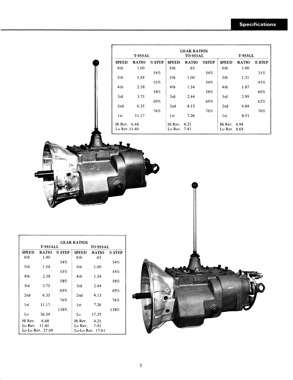
The T-955AL and T0-955AL six speed models have ratios
for construction vehicles, especially dump truck operation.
The 11.17 low gear provides ample reduction for starting
heavy loads, yet can
ping vehicle. The two reverse ratios, progressively shifted,
provide fast backing speeds plus deep reduction for job-site
spotting. The T0-955AL overdrive model
drive ratio where heavy duty drive axles are needed and
ratio choices are limited.
of
the power curve
give
the ratio spread necessary for construction
be
of
the high torque
shifted progressively without stop-
gives
rise
en-
a .65 over-
Specifications
Speeds
T-955AL, GL: 6 forward speeds, 2 reverse
T-955ALL: 7 forward speeds, 3 reverse
The T-955ALL and T0-955ALL seven speed models,
cially suited for
the reduction for extremely adverse conditions, also ratios
for curbing and paving. Three reverse ratios
stockpiling,
T0-955ALL overdrive model
speeds when heavy duty axle ratio choice
The T-955GL model has special
vehicles operating primarily on highway.
Torque
Clutch
both
job-site
Rating
Housing
dump and mixer operations, provide
give
work and load spotting. The
is
available to obtain highway
is
limited.
"gathered" ratios for
950 lb.-ft.
Size
SAE
No. 1, 2 aluminum
espe-
a range for
Power
PTO
Take-Off
Right Side: regular duty, 6-bolt type
45
tooth
PTO gear
Bottom: heavy duty, 8-bolt type
4 7
tooth
PTO gear
Gear
Relative
T-955AL: .533, right side and
T-955GL: .700, right side and
T0-955AL: .820, right side and
T-955ALL: .533, right side and
T0-955ALL: .820, right side and
Speed
to
Input
bottom
bottom
bottom
bottom
bottom
R.P.M.
Length
splines
(from
on
T-955AL, GL: 30
T-955ALL: 34
face
tailshaft)
Weight
T-955AL, GL: 580 lbs.
T-955ALL: 646 lbs.
Oil
Capacity
T-955AL, GL:
T-955ALL: 28
(pints)
of
25
clutch
7/8"
1/16"
housing
to
end
of
4
Page 8
T-955AL
SPEED RATIO %STEP
6th
1.00
SPEED RATIO %STEP SPEED RATIO %STEP
6th
T0-955AL
54% 54%
GEAR RATIOS
5th
1.54
5th
1.00
55% 54% 43%
4th
2.38
4th
1.54
58% 58%
3rd
3.75
3rd 2.44 3rd 2.99
69% 69% 62%
2nd 6.35
2nd
4.13
76%
1st 11.17 1st 7.26
Hi
Rev.
Lo
Rev. 11.40
6.48
Hi
Rev. 4.21
Lo
Rev. 7.41
.65
T-955GL
6th
1.00
31%
5th
4th
1.31
1.87
60%
2nd 4.84
76% 76%
1st 8.51
Hi
Rev.
Rev.
4.94
8.69
Lo
T-955ALL
SPEED RATIO
6th
5th
4th
3rd
2nd
1st
Lo
Hi
Rev.
Lo
Rev.
Lo-Lo Rev.
1.00
1.54
2.38
3.75
6.35
11.17 1st
26.54
6.48
11.40
27
.09
RATIOS
GEAR
T0-9SSAL
%STEP SPEED RATIO
6th
54%
5th
1.00
%STEP
.65
54%
55% 54%
58%
4th
3rd
69%
2nd
76%
1.54
58%
2.44
69%
4.13
76%
7.26
138% 138%
Lo
Hi
Lo
Rev.
Rev.
17.25
4.21
7.41
Lo-LoRev. 17.61
5
Page 9

Operation
In the following instructions it is assumed that the driver
coordinate the necessary movement
of
the shift lever and clutch pedal
either direction, up or down.
Six
Speed Models
T-955AL, T-955GL & T0-955AL Models
To shift from neutral to:
1st
- shift thru 2nd.
Reverse
T0-955AL
lo-
the
shift thru reverse-hi
On overdrive model
5th & 6th
speed positions are reversed
1.
Start engine with gear shift lever in the neutral position.
2. To start vehicle moving, shift into the 1st speed position.
This
is
done by moving the gear shift lever through the
gear
2nd speed
may be necessary to feather clutch
2nd).
Move
position with the clutch disengaged (it
to
move lever into
lever through the 2nd speed gear position to
the extreme left, then push lever forward into 1st gear.
NOTE:
the neutral position between
neutral position
While
moving the lever into first
can
be used
2nd
and 1st
at
stop lights, etc.
you
may feel
gears.
This
is
familiar with motor trucks and tractors, and that he can
to
make progressive and selective gear engagements in
3. After vehicle has gained sufficient speed in 1st gear, shift
lever into the 2nd speed position.
4. Shift from 2nd to 3rd
by
moving lever from the extreme
right in the second speed gear position into the 3rd
speed position.
NOTE: A spring and plunger will move the gear shift
lever to the extreme right
When
shifting from 1st to
in
the
2nd
speed
gear
2nd
the gear shift lever will be
position.
moved to the extreme right position; when shifting from
2nd
to 1st, operator must move lever to the extreme left
in
position while
2nd gear position against the spring
pressure.
5. Shift on upward through
pattern.
On
overdrive models, the
4th,
5th
and 6th in the shift
5th
and 6th speed gear
positions are reversed.
Reverse and
To
shift into reverse, move the gear shift lever into the
Lo
Reverse
reverse gear position.
To
shift into Lo reverse; first shift into reverse, then move
lever to the extreme left and forward into the lo reverse
position (it may be necessary
to
feather clutch to move
lever into reverse.)
6
Page 10
Seven
Speed
Models
T-955ALL and T0-955ALL Models
To shift
from
- shift thru
neutral
2nd.
1st
to:
Overdrive
T0-955ALL
the
5th
positions are reversed.
Shift
lo-lo
selector lever
to
"In"
position for
lo-lo
and
lo-lo
reverse.
models
and
6th
speed
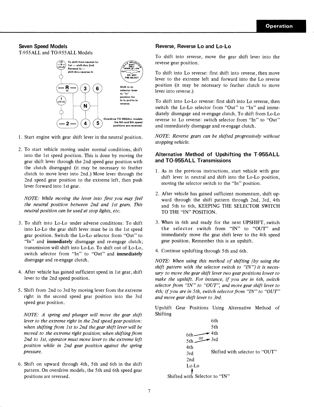
Reverse,
To
Reverse
Lo
and
Lo-Lo
shift into reverse, move the gear shift lever into the
reverse gear position.
To
shift into Lo reverse: first shift into reverse, then move
lever to the extreme left and forward into the Lo reverse
position (it may be necessary to feather clutch to move
lever into reverse.)
Lo
To shift into Lo-Lo reverse: first shift into
switch the Lo-Lo selector from
diately disengage and re-engage clutch.
reverse to
Lo
reverse: switch selector from
"Out"
To
reverse, then
to
"In"
and imme-
shift from Lo-Lo
"In"
to
"Out"
and immediately disengage and re-engage clutch.
1.
Start engine with gear shift lever in the neutral position.
To
start vehicle moving under normal conditions, shift
2.
is
into the 1st speed position. This
done by moving the
gear shift lever through the 2nd speed gear position with
the clutch disengaged (it may be necessary to feather
clutch to
move
lever into 2nd.)
Move
lever through the
2nd speed gear position to the extreme left, then push
lever forward into 1st gear.
NOTE:
the neutral position between 2nd and 1st
neutral position
3.
To
While
moving the lever into first
you
may feel
gears.
can
be used at stop lights, etc.
shift into Lo-Lo under adverse conditions: To shift
into Lo-Lo the gear shift lever must be in the 1st speed
gear position.
"In"
and immediately disengage and re-engage clutch;
transmission will shift into Lo-Lo. To shift out
switch selector from
Switch the Lo-Lo selector from
"In"
to
"Out"
and immediately
"Out"
of
disengage and re-engage clutch.
in
4. After vehicle has gained sufficient speed
1st gear, shift
lever to the 2nd speed position.
5.
Shift from 2nd to 3rd by moving lever from the extreme
right in the second speed gear position into the 3rd
speed gear position.
NOTE: A spring and plunger will move the
lever to the extreme right
in
the 2nd speed
gear
gear
position:
when shifting from 1st to 2nd the.gear shift lever will be
moved to the extreme right position; when shifting from
2nd to 1st, operator must move lever to the extreme left
position while
in
2nd
gear
position against the spring
pressure.
6.
Shift on upward through
pattern.
On overdrive models, the
4th,
5th
and 6th in the shift
5th
and 6th speed gear
positions are reversed.
This
to
Lo-Lo,
shift
NOTE: Reverse
gears
can
be shifted progressively without
stopping vehicle.
Alternative Method
and
T0-955ALL
1.
As
in the previous instructions, start vehicle with gear
of
Upshifting the
Transmissions
T-955ALL
shift lever in neutral and shift into the Lo-Lo position,
moving the selector switch to the
"In"
position.
2. After vehicle has gained sufficient momentum, shift upward through the shift pattern through 2nd, 3rd,
and
5th
to 6th, KEEPING THE SELECTOR
TO
THE
"IN"
POSITION.
4th
SWITCH
3. When in 6th and ready for the next UPSHIFT, switch
the
selector
immediately move the gear shift lever
gear position. Remember this
4. Continue upshifting through
NOTE:
When
shift pattern with the selector switch to "JN")
sary
to move the
make the upshift. For instance,
selector from
4th;
if
you
are
and move
gear
U pshift Gear Positions Using Alternative Method
switch from
is
5th
using this method
gear
shift lever two gear positions lower to
if
"IN"
to "OUT", and move
in
5th, switch selector from
shift lever to 3rd.
"IN"
to
"OUT" and
to
the
4th
an upshift.
and 6th.
of
shifting (by using the
it
is
you
are
in
6th, switch
gear
shift lever to
"IN"
to "OUT"
speed
neces-
of
Shifting
6th
5th
6th
__
5th
_2!.--3rd
4th
4th
3rd
Shifted with selector to "OUT"
2nd
Lo-Lo
t
Shifted
with Selector to
"IN"
7
Page 11

To
Convert
From
T-955AL
To
T0-955AL,
To convert from an T-955AL or T-955ALL to
drive
model T0-955AL or T0-955ALL the fifth speed gear
on the mainshaft and mating gears, one on each countershaft, are interchanged with the main drive gear and mating
countershift drive gears.
The transmission front section must be completely
assembled to make the change
as
the drive gear on each
INTERCHANGE THESE TWO SETS OF GEARS.
or
T-955ALL
an
over-
dis-
(3 Gears
To
T0-955ALL
countershaft must be removed. When reassembling make
sure gear hubs are in the right position
detailed reassembly section
Extra parts, other than gaskets, are not needed to make
the conversion. A new drive gear bearing nut may be
needed
in
each set)
as
this part may be damaged during removal.
of
this manual.
as
described
in
the
FRONT SECTION OF T-955AL
8
AND
T-955ALL
Page 12
Special
Procedure
For
Changing
In some cases in field repair it may be necessary to
place only the input shaft due to clutch wear on the splines.
In these instances the input shaft can be removed
out disassembling the transmission other than removing the
shifting bar housing. Removal
tional. Following
is
the detailed procedure:
of
the clutch housing
Clutch
re-
with-
is
op-
Disassembly
1.
Remove gear shift lever housing and shift bar housing
from transmission.
2. Remove the front bearing cover.
3. Engage the mainshaft sliding clutches in two gears and
remove the drive gear bearing nut.
4.
Move
the drive gear assembly
and remove the drive gear bearing.
5. Remove the washer from input shaft.
6.
From the front, remove the snap ring from
gear.
7.
Pull the input shaft forward and from splines
gear.
as
far forward
as
ID
possible
of
drive
of
drive
(Input)
Shaft
Reassembly
1.
Install new input shaft into splines
enough to expose snap ring groove in
of
2. Install snap ring in ID
3. Install washer on shaft.
IMPORTANT
4.
contact end
between rear
speed gear. When installing bearing this will hold input
shaft in position
5. Install drive gear bearing on shaft and into case bore,
making sure blocking remains in place.
6. Remove blocking from mainshaft and install the drive
gear
bearing nut, left-hand thread.
threads
7.
Peen nut into milled slots in shaft.
8. Re-install front bearing cover, shifting bar housing and
gear shift lever housing.
NOTE:
input shaft only.
disassembly
-
Move
of
input shaft in hub
of
to
of
nut and shaft.
The above instructions
of
the front section must be
drive gear.
the sliding clutch gear forward to
sliding clutch and front
seat the bearing properly.
To
change the drive
of
drive gear just far
ID
of
drive gear.
of
drive gear. Block
of
Use
Loctite sealant on
are
for changing the
gear,
made.
the fifth
complete
9
Page 13
Ei.!j1ffo.l,I
___________________________
_
Lubrication
RECOMMENDED LUBRICANTS
Heavy-duty engine oil. Make sure to specify heavyduty type meeting MIL-L-2104B specifications.
Mineral gear oil inhibited against rust, oxidation and
foaming.
Extreme pressure oils under some conditions might
form carbon deposits on gears, shafts, bearings and
synchronizer discs, and may also glaze friction
faces
of
synchronizer discs - conditions which will
result in transmission malfunction and premature
failure.
and E.P. oil
mineral oil or heavy-duty engine oil
It
is
suggested that
is
being used, a change should be made to
if
these conditions exist,
as
recommended.
sur-
ON-HIGHWAY
Type
Heavy Duty Engine
MIL-L-2104B
Mineral Gear Oil
Rand
0 Type
Mild
E.P.
Oil
Sulfur-chlorine-lead type)
MIL-L-2105B
OFF-HIGHWAY
Heavy Duty Engine Oil
MIL-L-2104B
Special Recommendation - For extreme cold weathe1
where temperature
Heavy Duty Engine Oil
MIL-L-2104B
(except
is
Oil
AND
consistently below
VEHICLES
Grade Temperature
SAE 50 Above + 1
SAE
SAE90
SAE
SAE90
SAE
MINING
SAE 50
SAE30
SAE
Below + 1 ooF.
30
Above +
80
Below + 1
Above + 1
80 Below + 1
EQUIPMENT
Above + 1
Below + 1
o°F.
20W
Below ooF.
o°F.
I0°F.
o°F.
o°F.
o°F.
o°F.
o°F.
FULLER TRANSMISSIONS
ate in a bath
parts have built-in channels where needed, to help lubricate bearings and
shafts.
Thus,
followed:
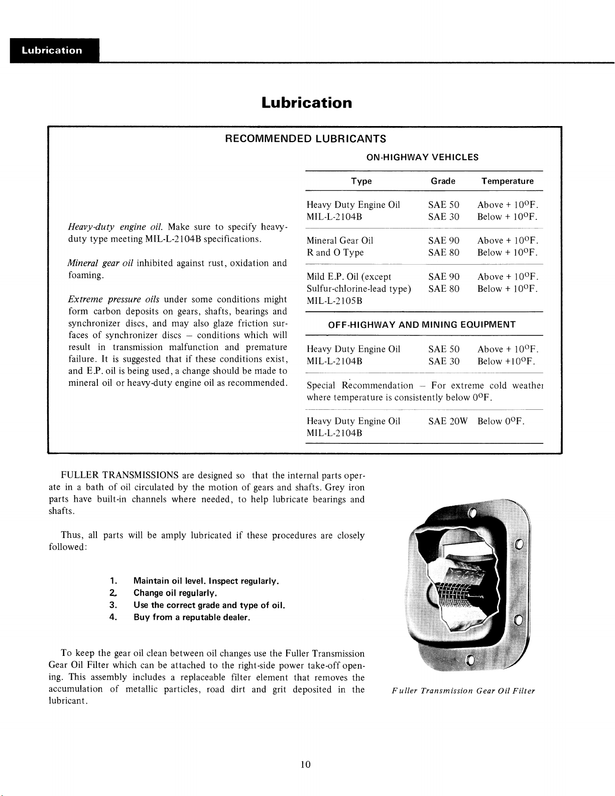
To keep the gear oil clean between oil changes use the Fuller Transmission
Gear
Oil Filter which can be attached to the right-side power take-off opening. This assembly includes a replaceable filter element that removes the
accumulation
lubricant.
of
oil circulated by the motion
all
parts will be amply lubricated
1. Maintain oil level. Inspect regularly.
2.
Change
3.
Use
the correct
4. Buy from a reputable dealer.
of
metallic particles, road dirt and grit deposited in the
are designed
oil regularly.
grade
so
that the internal parts oper-
of
gears and shafts. Grey iron
if
these procedures are closely
and
type of oil.
10
Fuller
Transmission Gear
Oil
Filter
Page 14
Draining Oil
Inspection
To
drain the transmission remove the drain plug at
the bottom
of
the front case. Drain oil when transmission
is
warm. After the transmission has been drained and before it
is
refilled, the
clean flushing oil or kerosene.
pound
if
pressure lubrication pumps unless pump
unit
case
should be thoroughly flushed with a
Do
not
use
flushing com-
is
equipped with side or front mounted
is
removed and
opening covered with plate. Clean both drain plugs before
reinstalling.
Refilling
In order to assure complete filling
of
the transmission
with oil, the following two methods may be used:
1)
At any inclination: Plug the fill hole in the front
case
and add entire quantity through opening in shift bar
housing. The transmission must be
completely drained
before using this method in order to avoid overfilling.
At
upgrade inclinations from 0 through 3 degrees:
2)
Add sufficient quantities through the fill hole to level
the oil at the
bottom
of
the fill hole.
Gear oil
opening at all times.
Highway
Off-highway Service
Gear Oil Change
Change the gear oil on
is
to be kept even with the level
Check at the following intervals:
Service
.....................
....................
all
new equipment after the first
of
the filler
.1,000 miles
.40 hours
3000 to 5000 miles (on-highway), or first 40 hours (off-
highway); thereafter, make oil changes
Highway Service
Off-highway
.....................
Service
Logging and associated operations
as
follows:
......
25
,000 miles
1,000 hours
Dirt moving, mining and
associated operations
............
250 to 500 hours,
as indicated by operation and contamination
lubricant.
of
Do
not overfill. Overfilling will cause the oil to be
forced out
Adding Oil
intermixed because
made through the fill hole
the fill hole with the transmission at a 0
of
the
case
through the mainshaft openings.
It
is
recommended that types and brands
of
possible incompatibility.
Additions
of
oil during servicing operations should be
to
level the oil at the
of
oil not be
bottom
to
3 degree
of
upgrade angle.
Operating Temperature
It
is
imperative that the operating temperature
transmission does not exceed
250°F.
Extensive operation at temperatures exceeding
will result in rapid breakdown
of
the oil and shorten trans-
of
the
250°F.
mission life.
Transmissions used in stationary equipment, or in
vehicles operating at slow road speeds, may have to be
so
equipped with external coolers
ture
is
not exceeded.
that the
250°F.
tempera-
Special Recommendation
The above oil inspection and change periods are based
on the average
tions listed.
make a periodic lab analysis
contamination based on the individual's own operating
use
and operating conditions for the applica-
It
is
recommended that the individual owner
of
the lubricant to determine
conditions. After this has been determined, the individual
owner can then set his own inspection and oil change
periods.
Clutch Release Bearing
Follow
vehicle manufacturer's chassis lubrication
recommendations.
Oil Filter
If
so
equipped, replace filter element at each oil
change; clean filter element housing.
11
Page 15

'i'fjij.iiijf
1
f
M
. l!IW'Sl!t?t''W'l''Sii.
------
12
Page 16
Preventive
Maintenance
Check
Chart
Preventive
Maintenance
CHECKS WITHOUT PARTIAL
DISASSEMBLY OF
CHASSIS OR
1.
Air
System
a.
Check for leaks, worn air lines, loose connections and
capscrews,
2. Clutch
a.
Check
looseness.
all
3. Clutch
a.
Remove hand hole cover and check radial and axial
clearances in release bearing.
b.
Check relative position
ing
with thrust sleeve on push type clutches.
4.
Clutch
a. Pry upward on shafts to check wear.
If
excessive movement
b.
mechanism and check bushings in bores and wear on
shafts.
5.
Gear
a.
Change at specified service intervals.
b.
Use
only gear oils
tion.
6.
Filler
a.
Remove filler plug and check level
fied intervals. Tighten filler and drain plugs securely.
and
Connections
See
Air Systems, page 94.
Housing
capscrews in bolt circle
Release
Pedal
Mounting
Bearing
of
Shaft
is
Lubricant
as
recommended.
and
Drain
Plugs
CAB
(T-955ALL)
of
clutch housing for
thrust surface
and
Bores
found, remove clutch release
of
release bear-
See
Lubrication
of
lubricant at speci-
sec-
Check
8.
Gear
Shift
a.
Remove the gear shift lever housing assembly from
transmission.
b.
Check tension spring and washer for set and wear.
c.
Check the gear shift lever pivot pin and pivot pin slot for
wear.
d.
Check
bottom
of
slot
contact points with shift lever.
yokes and blocks in shift bar housing for wear
CHECKS WITH
Chart
Lever
Housing
end
of
gear shift lever for wear and check
Assembly
DRIVE
LINE
DROPPED
Universal
9.
a.
Check for tightness. Tighten
CHECKS WITH UNIVERSAL
Joint
Companion
to
recommended torque.
Flange
JOINT
Nut
COMPANION FLANGE REMOVED
10. Output Shaft
a.
Check splines for wear from movement and chucking
action
of
the universal joint companion flange.
Pry upward against output shaft to check radial clear-
b.
ance in mainshaft rear bearing.
11. Mainshaft
a. Check oil seal for wear.
Rear
Bearing
Cover
at
7.
Gear
Shift
Lever
a.
Check for looseness and free play in housing.
loose in housing, proceed with Check No. 8.
If
lever
is
13
Page 17

General
Precautions
IMPORTANT: Read this section before starting
the
detailed disassembly procedures
It
is
assumed in the detailed disassembly instructions
that the lubricant has been drained from the transmission,
the necessary linkage and air lines removed and the transmission has been removed from the chassis. Removal
gear shift lever housing assembly
instructions; however, this assembly must also be removed
from transmission before removing unit from vehicle.
is
included in the detailed
of
the
for
Disassembly
ASSEMBLIES - When disassembling the various assem-
2.
blies, such
bar housing, lay
sequence
assembly and reduce the possibility oflosing parts.
as
the mainshaft, countershafts and shifting
all
parts on a clean bench in the same
as
removed. This procedure will simplify re-
The two control
the
transmission before removing unit from vehicle.
(T-955ALL)
Follow each procedure closely in each section, making
use
of
both
the text and pictures.
1.
BEARINGS - Carefully wash and relubricate
ings
as
removed and protectively wrap until ready for
use. Remove bearings with pullers designed for this
purpose.
REMOVED
CHISEL,
OUTER
BEARING
WITH
DAMAGED
RACE.
valve
air lines must be disconnected at
BEARING
REMOVED WITH
DAMAGED
PUNCH,
SHIELD.
all
bear-
oo
3. SNAP RINGS - Remove snap rings with pliers designed
for this purpose. Rings removed in this manner can be
reused.
INPUT SHAFT - The clutch or input shaft can be re-
4.
moved without removing the countershafts, mainshaft
drive gear.
5.
CLEANLINESS - Provide a clean place
important that no dirt or foreign material enters the unit
during repairs. The outside
fully cleaned before starting the disassembly. Dirt
abrasive and can damage bearings.
WHEN
6.
etc., with restraint. Movement
ed.
solidly.
work.
DRIVING - Apply force to shafts, housings,
Do
not apply force after the part being driven stops
Use
soft hammers and bars for
of
the unit should be care-
of
some parts
to
work.
is
all
disassembly
or
It
restrict-
is
is
14
Page 18
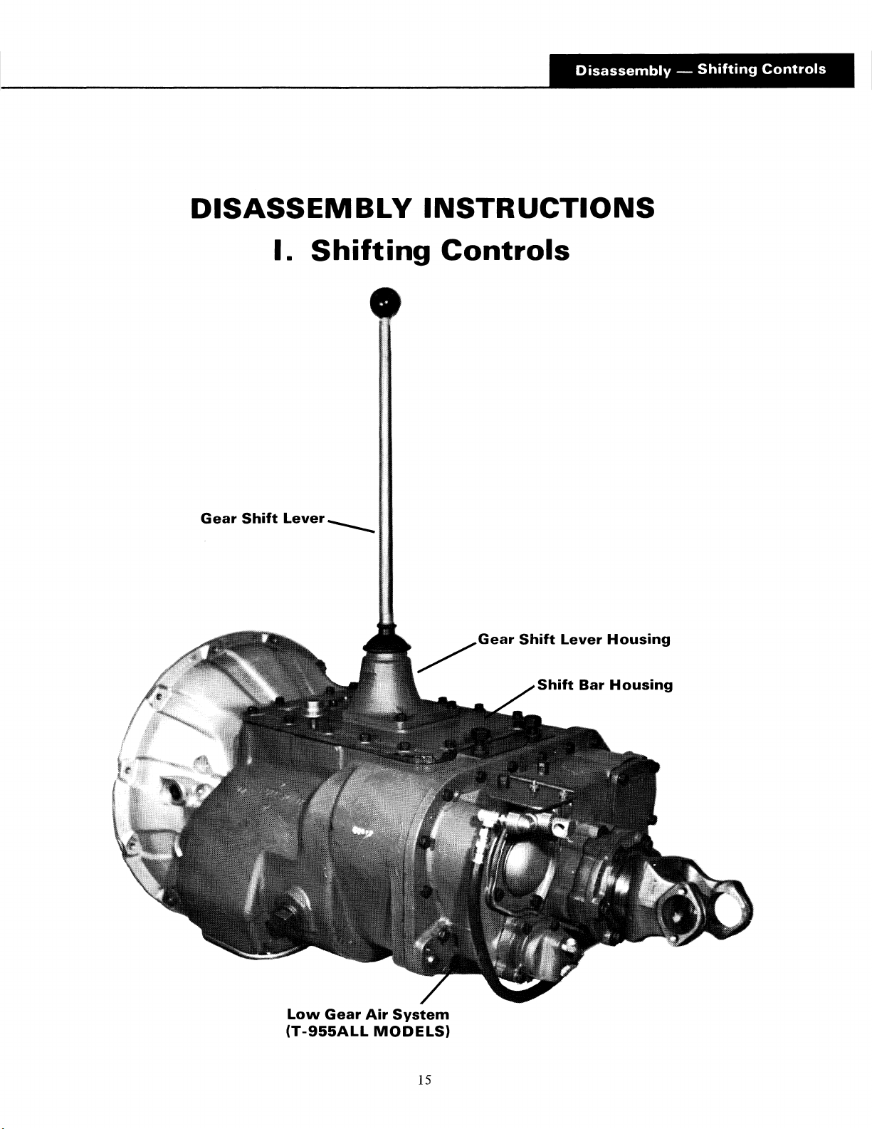
DISASSEMBLY
I.
Shifting
Gear
Shift
Lever
----
INSTRUCTIONS
Controls
Low
Gear
(T-955ALL
/Gear
Air
System
MODELS)
Shift
Shift
Lever
Bar
Housing
Housing
15
Page 19

l·HfHH,,'MW
_________________
_
A. Removal of the Low Gear Shift
LowGearShift
Coo"ol
V•"'•--
~
u-
11
i i
•
Y."
l.D.
Air
\___
Lines IF'
Air
System
+·
Tee
. . I
(T-955ALL
Cap screw
(2)
Reducer Bushing
Fitting
-o-u-Rmn-
\
Models)
~
'
l u U-BoU
'--
- -
--
----
Filter
-Air
Bracket
Filter
-.
Y." I .D.
Air
Line
1.
Disconnect
of
the
the
air line between
air filter and
the
the
low gear shift cylinder.
L~
G~'
tee
fitting forward
Shrr.
Cyllod"
~'\''
c~"~
Turn
out
2.
bracket assembly.
the
the
filter, refer
'icj
two
capscrews and remove
For
disassembly and maintenance
to
page 94.
the
air filter and
of
16
Page 20
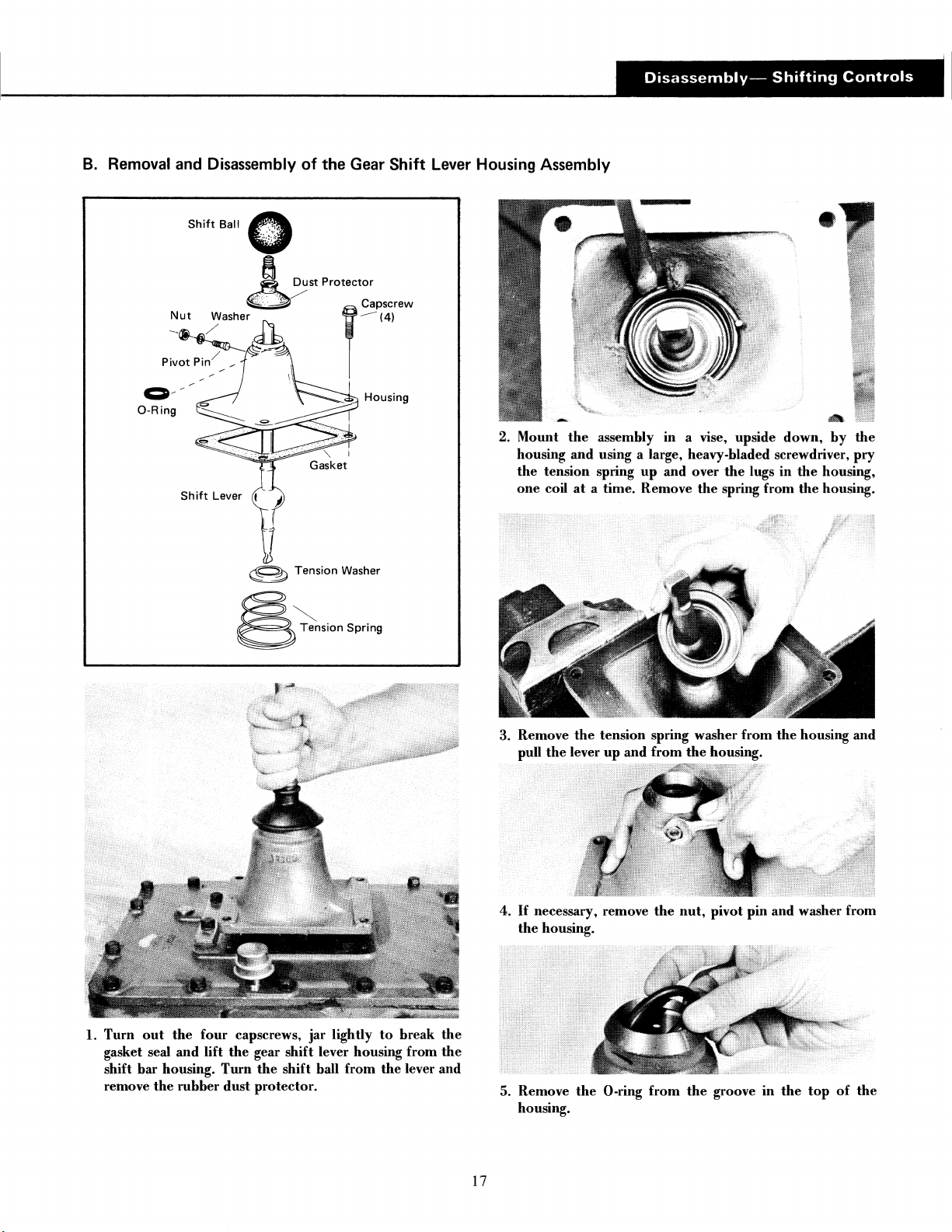
B.
Removal and Disassembly
of
the Gear
Shift
Lever Housing Assembly
ca
Tension Washer
~
';:;;,,;o"
Spd,_
2. Mount
housing and using a large, heavy-bladed screwdriver, pry
the
one
3. Remove
pull
the
assembly in a vise, upside down,
tension spring
coil
at
a time. Remove
the
tension spring washer
the
lever
up
and
up
and over
from
the
the
housing.
the
lugs
in
spring from
from
the
by
the
housing,
the
housing.
housing and
the
1.
Turn
out
the
gasket seal and lift
shift bar housing.
remove
the
rubber
four
capscrews, jar lightly
the
gear shift lever housing from
Turn
the
shift hall from
dust
protector.
to
the
break
the
the
lever and
4.
5. Remove
17
If
necessary, remove
the
housing.
the
0-ring
housing.
the
from
nut,
pivot pin and washer from
the
groove
in
the
top
of
the
Page 21

C. Removal and Disassembly
--
Capscrews
- Tensions Spring Cover
of
the
Shift
Bar Housing Assembly
Plug
@
GasketO
'
00
1
/e
Reverse~
Light
Pin
Capscrew
(161
/
I
11
/ Tension Balls
I/
00
Tension Springs
@Plug
(41
(41
Shift
/
Bar Housing
Gasket
1st
Low
Reverse Block,
Reverse
Shift
Bar
And
Yoke
2nd
Speed~~
Bar and
Yoke
3rd -4th
Bar and
Speed
Yoke
~/
'
~
18
Shift
Lockscrew
\
----~~
lunger
-Spring
\
--Plug
Page 22
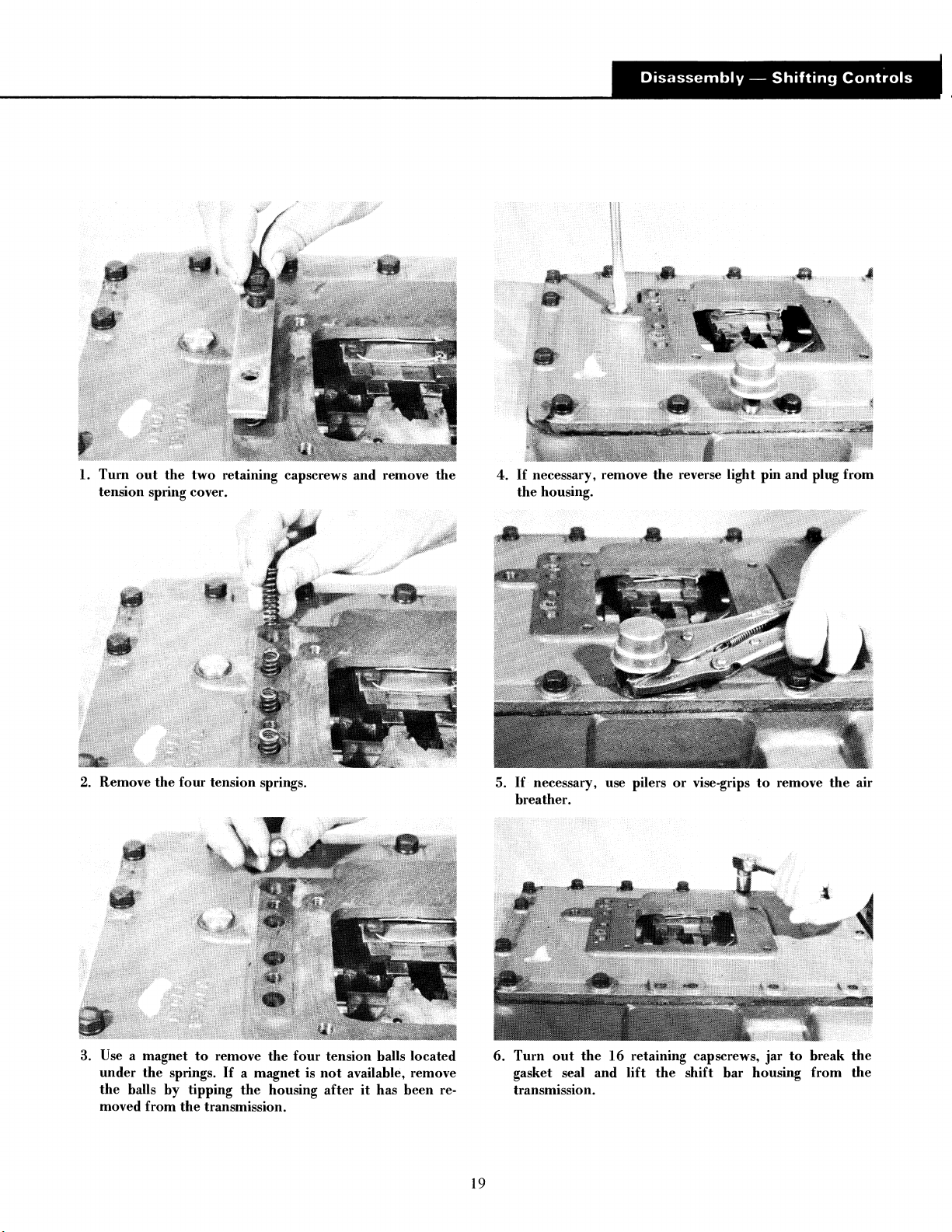
1.
Tum
out
the
tension spring cover.
two
retaining capscrews
and
remove
the
4.
If
necessary, remove
the
housing.
the
reverse light pin
and
plug
from
2. Remove
Use a magnet
3.
under
the
the
halls
moved
the
by
from
four
tension springs.
to
remove
springs.
tipping
the
transmission.
the
If
a magnet is
the
housing
four
tension balls located
not
available, remove
after
it
has
been
re-
5.
6.
19
If
necessary, use pilers
breather.
Tum
out
the
16
gasket seal
transmission.
and
or
vise-grips
retaining capscrews,
lift
the
shift
bar
to
remove
jar
to
housing
the
break
from
air
the
the
Page 23

C.
Removal and Disassembly
of
the
Shift
Bar Housing Assembly - continued
NOTE:
place all parts in their
bench, placing
each bar. Bars
neutral position
preventing removal.
7. Mount
shift bar
lockscrew and pull
from
sary, use a screwdriver
the
In
the
the
shift
to
the
the
shift
spring and plunger from
following steps
order
the
correct shift yokes and blocks
not
being removed
or
interlock parts will lock
bar
housing in a vise with
top
and
the
short (5th-6th speed) shift bar
yoke
and web
to
for
of
rentoval
cut
all lockwires.
of
tum
out
the
shift yoke.
ease
of
on
must
he
the
housing.
the
plug and remove
reassembly,
a clean work-
on
kept
in
the
the
bars,
the
shortest
Tum
out
the
If
neces-
9. Turn
out
shift bar from
and block.
the
two
lockscrews and pull
the
web
of
the
housing and
the
2nd-reverse
the
shift
yoke
8. Turn
bar from
clears
the
out
the
bar.
the
lockscrew and pull
the
yoke
and web
web
the
interlock pin will fall from
of
the
3rd-4th speed shift
the
housing.
As
the
the
bore
bar
in
10. Turn
11. Three interlock balls are located
out
the
two
lockscrews and pull
verse shift bar from
shift
yoke
and block.
housing. These will fall from
bar
is
removed
web.
the
or
may have
web
20
of
the
to
the
in
web as
he
the
1st-low re-
housing and
the
web
of
the
last shift
removed from
the
the
the
Page 24

12. Mount
remove
13. Turn
spring retaining plate.
the
the
out
the
1st-low reverse shift block in a vise and
two
sets
of
lockwires.
two
lockscrews evenly and remove
the
15.
Turn
out
retaining plate.
16. Remove
from each block.
the
the
two
lockscrews and remove
two
blocks and remove
the
the
interlock pin
block
14. Remove
the
two
springs
from
the
bores.
21
Page 25
'·BiHi+"M
1
lli'NNh.iiH'·
1
·B+b'+'·m
1
1
•
iM.t.iiifiiiif
Biiii"+I..._
_________
_
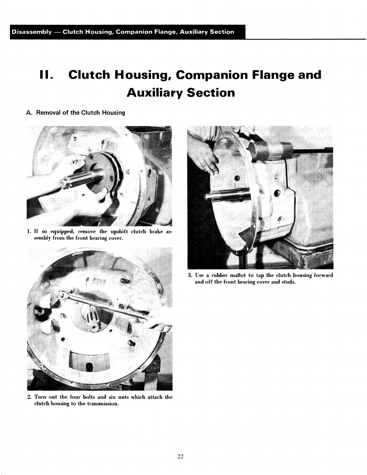
II.
A. Removal
1.
If
so equipped, remove
sembly from
Clutch
of
the Clutch Housing
the
the
front
bearing cover.
Housing,
Auxiliary
upshift clutch brake as·
Companion
Section
Flange
and
2.
Turn
out
clutch housing
the
four
bolts and six
to
the
transmission.
nuts
which
attach
the
3. Use a rubber mallot
and
off
the
front
bearing cover and studs.
to
tap the
clutch housing forward
22
Page 26

B.
1.
Turn
C.
Removal
Removal
the
elastic stop
of
the Companion Flange
nut
from
the
of
the
Auxiliary
Rear Section
Disassembly
or
output
shaft.
Yoke
-
Clutch
2. Pull
Housing,
the
the
output
or
spacer
Companion
companion flange
shaft and remove
from
the
flange
or
Flange,
or
yoke
the
yoke.
Auxiliary
from
the
speedometer drive gear
splines
Section
of
1.
Turn
out
the
19
capscrews retaining
to
the
front
case.
NOTE: With T-955AL and GL series transmissions,
may be necessary
right corner
the
top
right retaining capscrews.
2.
Insert
three
flange
of
break
the
from
the
front
imately
Y2".
the
to
remove
of
the
auxiliary section
puller screws
auxiliary section and tighten evenly
gasket seal
case. Move
and
in
move
the
the
auxiliary section
the
plate located
to
allow access
the
tapped holes in
the
rear section away
rear housing back approx·
at
the
it
top
to
the
to
3. Remove
23
the
top
the
rear housing
NOTE:
the
output
the
puller screws and
of
the
rear housing. Use a chain hoist
off
It
is
advisable
shaft
to
attach
the
front
case dowel pins.
to
re-install
avoid damage
a hanger bracket
the
elastic stop
to
the
threads.
to
move
nut
to
on
Page 27

Ill.
Front
Section
A. Removal and Disassembly
Bearing Retaining Snap Ring
of
the
Auxiliary Drive Gear Assembly
Retaining
Snap Ring
Capscrew (6)
1. Cut
retaining
case.
the
two
lockwires and
the
auxiliary drive gear assembly
turn
out
the
six capscrews
to
the
front
24
2.
Remove
mainshaft.
the
snap ring
from
the
groove
in
the
rear
of
the
Page 28

3. Insert three puller screws
retaining ring and tighten evenly
to
the
rear and
4. Remove
the
auxiliary drive gear.
from
the
snap ring from
the
case bore.
in
the
the
to
groove
tapped holes
move
the
on
the
of
the
assembly
front
of
5.
Support
use a mall and driver
the
the
assembly
hearing. This will free
in
to
a vise
drive
the
by
the
retaining ring and
the
gear
down
retaining ring.
and
from
25
Page 29

B.
Removal
of
the
Left
Reverse
Idler Gear Assembly
Bearing
Needle Bearing \
\
Inner
Race
Rear Washer
1.
Remove
the
snap ring
mainshaft reverse gear.
2. Move
against
the
reverse
sliding
the
reverse gear forward
the
1st speed gear, engaging
and
clutch
gear.
1st
speed gears
from
the
ID
on
with
of
the
the
the
the
hub
mainshaft
splines
of
splines
of
of
the
and
both
the
3. Remove
26
the
elastic
the
idler shaft.
4.
Use inside jaw pullers
tershaft
auxiliary
moved
front
countershaft
at
this
time.
stop
bearing
nut
to
from
front
and
remove
the
bearing
washer
the
left
case
from
the
end
auxiliary coun-
bore.
The
may
also be re-
of
right
Page 30
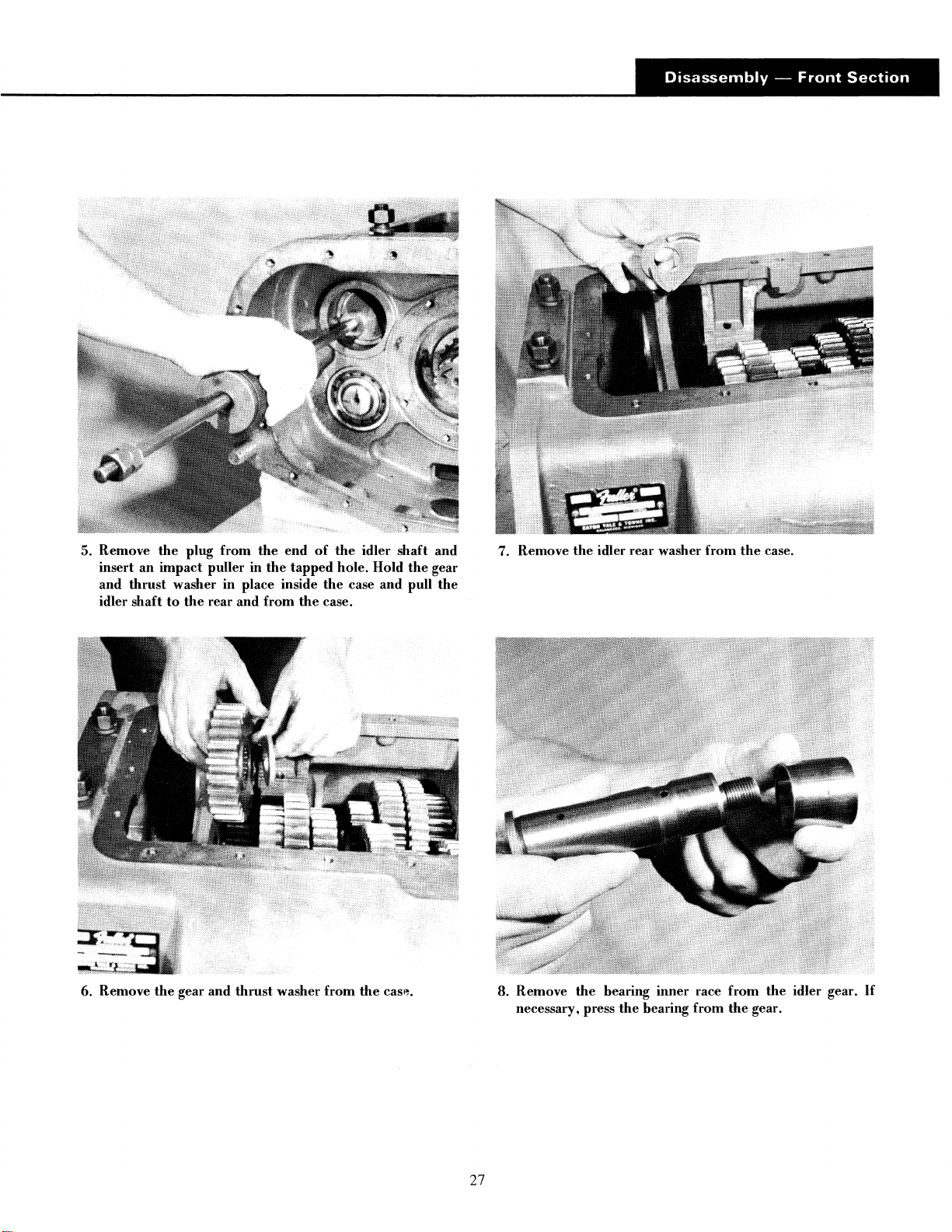
5. Remove
an
insert
and
thrust
idler shaft
the
plug from
impact puller
washer
to
in
the
rear and from
the
end
in
the
tapped
place inside
the
of
the
hole. Hold
the
case and pull
case.
idler shaft and
the
gear
the
7. Remove
the
idler rear washer
from
the
case.
6. Remove
the
gear and
thrust
washer from
the
cas".
8. Remove
27
the
hearing inner race from
necessary, press
the
hearing from
the
the
gear.
idler gear.
If
Page 31

C. Removal
of
the Right Countershaft
Bearings
1. Remove
right countershaft.
the
snap ring
from
the
groove
in
the
rear
of
the
3. Cut
move
sary
the
4.
Use a
possible
the
lockwire,
the
front
to
lock
the
lockscrews.
soft
bar
to
the
tum
out
the
two
bearing retaining plate.
trnnsmission
and mall
rear.
to
drive
in
the
two
lockscrews and re-
It
may
be
neces-
speeds
countershaft
to
remove
as
far
as
2.
Use a mall and
against
to
NOTE: Removal
generally result
be
planned.
the
the
rear and
attempted
punch
or
other
inner race
from
of
the
the
case
of
the
countershaft
in
damage
unless replacement
similar
pointed
bearing
bore
to
the
to
and countershaft.
bearings and should
of
instrument
drive
the
bearing
rear bearings will
not
the
bearings is
28
Use a
5.
to
unseat
ing puller
soft
drive
bar
and mall
the
shaft as far forward as possible. This will
the
front
bearing
to
remove
the
on
the
from
bearing
rear
of
the
the
case bore. Use a bear-
from
the
countershaft
countershaft.
Page 32

0.
Removal and Disassembly
Small Splined
Spacer
Small
Washe~
Small
Sliding
Clutch
\
~';"·~
/
Small Snap Ring
5th
Speed Gear
of
the
Mainshaft Assembly
4th
Speed Gear
Key
3rd
Speed Gear
\
\
Mainshaft
Large
2nd
Speed Gear
Sliding
\
Clutch
(2)
Large
Splined Spacer (4)
"'Large
Snap Ring (4)
Reverse Gear
1. Block
and
the
front
ward
gears
shaft. Use
from
the
pull
and
on
the
right
countershaft
the
mainshaft as far
of
the
mainshaft
lift
the
mainshaft
the
mainshaft
caution
mainshaft.
as
against
up,
from
past
the
reverse gear is free and can fall
the
side
to
the
rear as possible. Tilt
move
the
the
case, working
the
gears
on
of
assembly for-
the
the
case
the
counter-
29
2. Place
reverse gear.
the
mainshaft
on
a workbench and remove
the
Page 33

D. Removal and Disassembly
of
the Mainshaft Assembly - continued
3. Remove
of
the
mainshaft.
4. Remove
clutch.
the
5th-6th speed sliding clutch from
the
key located
under
the
5th-6th speed sliding
the
front
6. Remove
mainshaft.
7. Remove
mainshaft.
the
the
5th
speed gear, spacer and washer from
4th
speed gear, spacer and washer from
the
the
5. Remove
mainshaft.
the
snap ring from
the
groove
in
the
rear
of
the
30
8.
Pull
the
the
mainshaft.
3rd-4th speed sliding clutch from
the
splines
of
Page 34

9. Use a pointed object
shaft until
the
other
to
end
push
the
extends
key
beyond
down
the
the
main-
mainshaft.
10. Pull
11. Remove
the
mainshaft.
key from
the
the
keyway.
reverse gear washer and spacer from
the
12. Pull
13. Remove
the
splines
spacers from
reverse-2nd speed sliding clutch from
of
the
mainshaft.
the
second and third speed gears, washers and
the
mainshaft.
the
E.
Removal
1. See page 28 as removal procedures for
tershaft bearings are identical.
of
the
Left
Countershaft Bearings
both
sets
of
coun-
31
Page 35

F. Removal and Disassembly
Bearing
Nut
Bearing
of
the
Input
Shaft and Drive Gear Assembly
Brass Bushing
1. Turn
out
bearing cover.
the
retaining capscrews and remove
the
front
32
2.
From
the
soft
necessary.
inside
the
snap ring can
bar and mall
case,
tap
be
removed from
to
move
the
drive gear forward so
the
the
drive gear forward if
that
bearing. Use a
Page 36

3. Move
the
drive gear assembly
working past
drive gear assembly
to
the
inside
the
countershaft assemblies. Remove
from
the
case.
of
the
case,
the
5.
Turn
the
bearing
nut
from
the
shaft (left
hand
thread.)
4. Relieve
the
bearing
nut
where
it
is
peened
into
the
shaft.
Press
6.
sary, remove
Check
place if damaged.
33
the
shaft through
the
bushing
the
snap ring from
in
the
the
bearing and gear.
the
pocket
of
the
ID
input
of
If
neces-
the
gear.
shaft; re-
Page 37

G. Removal and Disassembly
Bearing Retainer Plate
~JJ
Retainer Capscrews
of
the
Countershaft Assemblies
Key~
I
/i
Roll Pin
1
1
1. Remove
the
case.
NOTE:
gears,
the
assembled
the
right
Except
for
countershaft
in
the
same manner.
and
left
countershaft
the
number
assemblies are identical
of
assemblies
teeth
on
the
and
from
PTO
dis-
2. Press
the
6th,
PTO,
5th
and
4th
countershaft. (This will require a press
capacity; use metal shield as a safety precaution.)
34
speed gears
of
at
least 25-ton
from
the
Page 38

IMPORTANT: Never use
the
pressing as
ceptible
larger diameter
to
breakage. ·
the
PTO gear as a base for
of
this gear makes
it
sus-
3. Press
H. Removal and Disassembly
1. Refer
the
3rd
speed gear from
remove
assemblies are identical and are disassembled
manner.
the
key and roll pin from
to
page
26
as
the
right and
the
the
of
the Right
left
shaft.
If
necessary,
shaft.
Reverse
reverse idler gear
in
the
same
Idler
Gear
Assembly
35
Page 39

IV.
Auxiliary
Section
A.
Removal
of
T-955AL,
the
First-Reverse Speed Sliding Clutch Gear
T-955GL,
Models
1. Insert a large screwdriver between
the
and
and
2.
Remove
shaft.
1st speed gear and
off
the
splines
the
tension hall from
of
the
pry
output
the
shaft.
the
the
sliding clutch gear
sliding
clutch
bore
in
the
forward
output
3.
Rotate
from
the
the
bore
output
in
the
shaft until
shaft.
the
tension spring falls
36
Page 40

B. Removal
Front
of
the Auxiliary Countershaft Assemblies
Bearing
3. Remove
countershaft.
the
snap ring
from
the
rear
of
each auxiliary
1.
If
not
previously removed,
screws and remove
2.
Tum
out
the
covers.
tum
out
the
rear cover.
capscrews and remove
the
retaining cap·
the
two
rear bearing
4.
5.
37
Use a soft
ward
the
bearing inner race
and
bar
from
Use a soft bar
the
housing bores. Tap
age
to
the
bearings.
and mall
the
rear bearings.
from
to
tap the
to
the
bearings
on
the
drive
front
outer
the
countershafts for·
If
necessary, remove
of
each shaft.
to
the
rear and from
race
to
avoid dam·
Page 41

C.
Removal
of
the
First Speed Gear,
Output
Shaft and Rear Bearing Assembly
First,
Low
Reverse Speed
Sliding
Clutch
. Bearing
~
Capscrew
./"....
/
"-...~···
(191
~
~~:::1-'\~·V
~·_G·
Oil
..
Seal
~pscrew(6)
I Plug Bushing
Plug
Gasket
Rear Bearing Housing
C~.~~~.
·.
(\
C~ew
.
·:
.
....
,
...
·/
j
..
·
Gasket
(4)
~
Stop
Nut
~·
\
Stepped
Spacer
First
Speed Gear
1.
Tum
out
hearing housing.
the
housing.
the
six retaining capscrews
If
necessary, remove
-,_Q
Tension Spring Tension Ball
and
remove
the
the
oil seal
rear
from
NOTE:
removal
of
the
2. Use a
and
The
oil seal will
and
should
seal is planned.
soft
bar
and
from
the
rear bearing assembly.
not
mall
most
likely
he
damaged during
he
removed unless replacement
to
drive
the
output
shaft
forward
38
Page 42

3. Remove
the
rear bearing
cone
from
the
rear housing.
5. Place
inner spacer.
the
output
shaft
on
end and remove
the
hearing
4.
Use a
spacer
soft
from
bar
the
to
tap the
bore
in
the
two
bearing cups
rear housing.
and
outer
6. Using
the
first speed gear as a base, press
ing cone
ing, gear, washer and spacer.
from
39
the
output
the
shaft. This will free
front
the
hearhear-
Page 43

V.
Auxiliary
Section
A. Removal
of
the Auxiliary Countershafts
T-955ALL,
Models
1.
Mount
tion,
turn
two
rear hearing covers.
Remove
2.
countershaft.
the
auxiliary
out
the
the
snap
section
attaching
ring
in
a vise
in
the
upright
capscrews and remove
from
the
rear
of
posi-
the
each
3. Use a soft
ward
the
4.
Use a
the
the
40
bar
and
from
hearing
case bores.
hearings.
soft
inner
bar
and
mall
the
rear hearings.
race
from
to
tap the
Tap
on
to
hearings
the
drive
the
outer
the
countershafts
If
necessary, remove
front
of
each shaft.
to
the
race
to
avoid damage
rear
and
for-
from
to
Page 44

Disassembly
-
Auxiliary
Section
B. Removal
Sliding
\
~-----~
_
Jl!f!!!}I
Clutch
of
the Sliding Clutch and First
Ke$-·
Pin
First
Speed Gear
Speed
Gear
4.
Turn
the
gear.
the
splined washer inside
teeth
align with
the
1st
speed gear until
the
grooves in mainshaft, freeing
the
1. Pry
the
sliding clutch forward and
range mainshaft.
2.
Rotate
plunger falls from
the
mainshaft until
the
bore
off
the
~plines
the
sliding clutch retaining
in
the
shaft.
of
the
5.
Pull
the
6. Remove
1st speed gear from
the
coupler
from
the
the
splines
splines
of
of
the
mainshaft.
the
mainshaft.
3. Remove
the
key from
the
groove
in
the
mainshaft.
41
Page 45

C. Removal and Disassembly of the Low Gear Shift Cylinder
Shift
Shift
Cylinder
Yoke
\
Housing
\ /
""'
~\
~
V.
Gasket
-~
\
Lock
screw
HousingO-Ring
Shift
Bar
\
Co~~
~fl
~f
\ Gasket
Shift
Bar
0-Ring
sh;ft
cvo;"'"
c~"
1. Cut
the
lockwire and
gear shift yoke.
turn
out
the
lockscrew
on
the
low
42
2. Turn
out
the
capscrews and remove
the
cylinder cover.
Page 46

3.
Pull
the
ing.
If
necessary, remove
diameter
4. Remove
If
necessary, remove
housing.
shift
bar
to
the
rear and from
of
the
bar.
the
cylinder housing from
the
the
0-ring
the
0-ring from
the
cylinder hous-
from
the
large
auxiliary housing.
the
bore
in
the
5. Remove
the
shift
yoke
from
the
sliding clutch.
43
Page 47

D. Removal
of
the
Range
Mainshaft
Tension Pin
Tension Spring
Bearing-~-©'~
-G-·~
au;u
S"•P
~~""
-~-
>
~
R;og
\
Range Mainshaft
Low
Speed Gear
\
Stepped
"'--
Output
Spacer
Stop
Shaft
Nut
1. Remove
quill.
2.
Use pry bars
ward and
the
snap ring from
or
equivalent
off
the
quill.
the
to
front
move
of
the
output
the
mainshaft for-
shaft
3. Remove
if necessary, remove
tension spring from
44
the
hearing from
the
bore
of
the
the
brass hushing, snap ring and
the
mainshaft.
mainshaft and,
Page 48

E.
Removal
of
the
Low Speed Gear,
Output
Disassembly
Shaft and Rear Bearing Assembly
-
Auxiliary
Section
1. Remove
shaft.
2.
Use a soft bar and mall
and from
the
sliding clutch from
the
rear bearing assembly.
to
drive
the
the
splines
output
of
the
output
shaft forward
4. Using
5.
the
low speed gear as a base, press
ing
cone
from
the
output
ing, gear, washer and spacer.
Turn
out
the
retaining capscrews and remove
bearing housing from
the
remove
bearing cone from
NOTE: Removal procedures will
oil seal and should
of
the
oil seal from
seal is planned.
the
the
rear housing.
not
be
.
......
the
shaft. This will free
auxiliary section.
the
housing. Remove
most
likely damage
attempted
unless replacement
front
the
the
If
necessary,
the
bear-
bear-
rear
rear
the
3. Remove
the
bearing inner spacer from
the
output
shaft.
45
6.
Use a soft
spacer from
bar
to
tap the
the
auxiliary housing bore.
two
bearing cups and
outer
Page 49

"++'ii".!.I
......
_________________________
Inspection
Before reassembling the transmission, the individual parts should be carefully checked to eliminate those damaged
from previous service. This inspection procedure should be carefully followed
rebuilt unit.
The cost
questionable part make additional repairs necessary before the next regularly scheduled overhaul.
Recommended inspection procedures are set forth in the following check list:
A.
Bearings
l.
Wash
all
bearings in clean solvent. Check balls, rolls and
races for pits and spalled areas. Replace bearings which
are
pitted or spalled.
2. Lubricate bearings which
are not spalled or pitted
and check for axial and
radial clearances. Replace
bearings
clearances.
of
a new part
with excessive
is
generally a small fraction
Spalled Bearing Extreme
Load
of
the total cost
D. Thrust
1.
Check
thrust
scored or reduced in thickness should be replaced.
E.
Reverse
1.
Check bearing sleeve for wear from action
bearings.
F. Gray Iron
to
Washers
surfaces
washers.
Gear
insure the maximum
of
downtime and labor, should the
of
all
Washers
and
Shaft
Parts
of
wear life from the
of
use
roller
of
_
a
Check fits
3.
case
turn freely in the bores,
the
replaced.
B.
Gears
1.
c«eck
faces. Gears with pitted teeth should be replaced.
Check all engaging gear teeth. Gears with teeth worn,
2.
tapered or reduced in length from clashing in shifting
should be replaced.
3.
Check axial clearances
ance
gear hub for excessive wear.
C.
Splines
1.
Check splines on
gears, companion flange or clutch hub have worn into
the sides
should be replaced.
of
bearings in
bores.
If
outer races
case
is
should
operating gear teeth for pitting on the
found, check gear snap ring, washer, spacer and
of
the splines, the shafts in this condition
be
o(
gears. Where excessive clear-
all
shafts for wear.
False Brinnelling -
Vibration Without
Rotation
If
sliding clutch
tooth
1.
Check
all
gray iron parts for cracks and breaks. Replace
or repair parts found to be
damaged. Heavy castings
may be welded or brazed
providing the cracks do
not extend into bearing
bores or bolting surfaces.
G. Clutch
1.
Check clutch release parts. Replace yokes worn at cam
surfaces and bearing carrier
worn at contact pads.
2.
Check pedal shafts. Re-
place those worn at bear-
ing surfaces.
Release
Parts
46
Page 50

H. Shifting Bar Housing Assembly
J.
Bearing
Covers
1.
Check yokes and blocks for wear at pads and lever slot.
Replace worn parts.
2.
Check
ment.
which are sprung.
3.
Check yokes for excessive
wear; replace worn yokes.
4.
Check lockscrews in yokes
and blocks. Tighten and
rewire those found loose.
5.
If
shifting bars for wear from interlock balls.
at points adjacent to the neutral notch should be
replaced.
yokes for align-
Straighten those
housing has been dismantled, check neutral notches
Bars
indented
of
1. Check covers for wear from thrust
Replace covers worn and grooved from thrust
outer race.
2.
Check bores
oversize.
Oil Return Threads
K.
1.
Check oil return threads in front bearing cover.
action
input shaft, replace the cover.
2.
Check oil seal in mainshaft rear bearing cover.
action
L.
Sliding Clutches
1.
Check
extreme wear or discoloration from heat.
of
covers for wear. Replace those worn
of
threads has been destroyed
of
lip has been destroyed, replace seal.
all
yokes and yoke slots in sliding clutches for
I. Gear Shift Lever Housing Assembly
2.
Check engaging teeth
1. Check spring tension on shift lever. Replace tension engagement pattern.
spring and washer
2.
If
housing
sponding slot in lever for wear. Replace
worn.
if
lever moves too freely.
is
dismantled, check pivot pin and corre-
both
parts
if
M.
Front Bearing Cover
1.
Check inside hub
by backing
off
of
drive gear bearing nut.
of
adjacent bearing.
of
and
Seals
If
by
contact with
If
of
sliding clutches for partial
of
front bearing cover for wear caused
bearing
sealing
sealing
Location
Seat gasket with shellac on part to be installed.
gaskets
Gaskets are located between the following parts:
T-955AL,
l.
2.
3. Reverse light plug.
4. Tension spring cover plate.
5.
6. Front bearing cover and case.
7. Rear plate and case.
throughout
GL
Gear Shift lever housing and shift bar housing.
Shift bar housing and case.
Clutch housing and case.
when reassembling transmission.
Use
new
of
Gaskets
8. Mainshaft rear bearing cover and rear plate.
9. Rear plate cover and rear plate.
10. Right aux. countershaft rear bearing cover and rear
plate.
Left aux. countershaft rear bearing cover and rear
11.
plate.
12. Large
13.
T-955ALL
To
1.
2. Low gear shift cylinder and case.
47
PTO cover and case.
Small PTO cover and case.
the above list add:
Low gear shift cylinder cover and cylinder.
Page 51

Torque
Ratings
Recommended torque ratings, location and thread sizes
Capscrew lengths are given for reference purposes
Correct torque application
is
extremely important to assure long transmission life and dependable
as
a guide for installation at proper locations.
of
capscrews and nuts are listed below.
performance. Over-tightening or under-tightening can result in a loose installation and, in many
instances, eventually cause damage
to
transmission gears, shafts or bearings.
Do
not torque capscrews
dry.
CAPSCREWS
Thread
Location
Filter Bracket 2
*PTO Cover, small 6
Low Gear
Aux. Drive Gear Retainer Ring 6
Shift Bar Housing
Gear
Front Bearing Cover 6
Countershaft Rear Bearing Covers 8
Rear Plate
Rear Plate to Case (T-955ALL only) 18
Mainshaft Rear Bearing Cover 6
PTO Cover, large 8
Outch
C/S
Shift Cylinder
(T-955ALL only)
Shift Lever Housing
to
Case (T-955AL, GL only) 18
Housing to Case
Front
Bearing Retainers
Qty.
16
Size
And
Length
3/8-16 x 3/4
3/8-16 x 3/4
4 5/16-18 x 1-7/8
3/8-16 x 1
3/8-16 x 1-1/4
4 3/8-16 x 1-1/4
3/8-16 x 1-1/4
3/8-16 x 1-1/4
3/8-16x2
1
1
2
2 1/2-13 x 3-1/2
4
3/8-16 x 1-3/4
3/8-16 x 1-1/2
3/8-16x2
3/8-16 x 2-3/4
7/16-14 x 1-1/4
1/2-13 x 1-1/2
1/2-20 x 1 50-65
Torque
Rating
Foot-Pounds
20-25
18-23
(12-15 with oil filter)
20-25
35-45
50-65
70-75
70-75
*NOTE:
away from
Reverse Idler Shafts
Outch
Drive Gear
Companion Flange
Installing
the
case with resultant oil leakage.
Housing
to
the
capscrews with more than 23 ft-lbs.
of
torque will force the corners
NUTS
Qty.
2
Case 6 5/8-18
1 2-1/8-16
or
Yoke 1
Thread
5/8-18
2-16
48
Size
of
the
Torque
Foot-Pounds
75-80
170-185
250-300
450-500
PTO cover
Rating
Page 52

General
Precautions
for
Reassembly
Make
sure that interiors
It
is
important that dirt be kept out
reassembly. Dirt
faces
of
bearings and washers.
listed below, during reassembly.
1.
GASKETS
sion
as
3.
0-RINGS - Lubricate
200 Fluid," 50,000
2.
CAPSCREWS
all
capscrews.
torque.
is
abrasive and can damage polished sur-
-
Use
it
is
being rebuilt. Make sure all gaskets are in-
- To prevent oil leakage,
See
of
new gaskets throughout the transmis-
stalled,
can result in oil leakage or
misalignment
covers.
kets" heading.
all
cs.
torque rating chart for recommended
IMPORTANT:
the
case
and housings are clean.
of
transmission during
Use
certain precautions,
as
omission
See
"Location
0-rings with "Dow Corning
use
Read this section before starting
detailed reassembly procedures.
as
of
gasket
of
bearing
of
Gas-
shellac on
7.
BEARINGS
commended for the installation
8.
UNIVERSAL
companion flange tightly into place with the mainshaft
nut, using
speedometer gear
the same width must be used. Failure to pull the yoke or
flange tightly into place will permit the shaft to move
axially with resultant damage to rear bearing.
-
Use
of
flanged-end bearing drivers
drivers apply equal force to
both
venting damage to balls and
races and maintaining correct
......
bearing alignment with shaft
and bore.
type driver
force only to inner race.
JOINT
450-500 foot-pounds
COMPANION
is
not used, a replacement spacer
of
bearings. These
races
of
bearing, pre-
If
tubular or sleeve
is
used, apply
FLANGE
of
torque. Make sure the
- Pull the
is
re-
of
4.
ASSEMBLY
guide to reassembly.
INITIAL
5.
splines
provide initial lubrication, preventing scoring and galling.
6.
AXIAL
ances
.012''. Mainshaft reverse gear clearance
.038". Refer to axial clearance chart on
reassembly
- Refer to the disassembly illustrations
LUBRICATION
of
shafts with Lubriplate during installation to
CLEARANCES
of
mainshaft forward speed gears
of
the mainshaft assembly.
- Coat all thrust washers and
- Maintain original axial clear-
of
is
page
.005" to
.005"
95 during
as
a
to
49
Page 53

REASSEMBLY
I.
Auxiliary
INSTRUCTIONS
Section
A.
Reassembly
of
the
Low Speed Gear and
T-955ALL,
Output
Shaft
Models
l.
Place
the
output
prevent damage
washer
on
shaft, threaded end up,
to
the
the
shaft, stepped side
quill and install
up.
on
blocking
the
to
splined
50
2.
If
previously removed, install
of
the
low speed gear and install
clutching
teeth
down.
the
snap ring
the
gear
in
on
the
the
groove
shaft,
Page 54

Reassembly
-Auxiliary
Section
(T-955ALL)
3. Install
the
rear washer
on
the
shaft, flat side
up.
NOTE: Heating
Do
not
heat
5.
Install
the
of
the
hearing will facilitate installation.
the
hearing over 275°F.
spacer
on
the
shaft.
4. Install
up.
the
front
hearing cone
on
the
shaft,
taper
facing
51
Page 55

B.
Installation
of
the
Rear Bearing Assembly
1. Place
the
rear housing, machined face down,
bench and using a rubber mallot
front
bearing cup into
ed
end
of
the
cup should face down.
the
on
a work-
or
equivalent,
rear housing bore. The taper-
tap
the
3. Place
the
driver
bore. The lip
housing.
rear bearing cup
to
tap
all
three
of
the
on
the
inner race and use a
evenly
rear cup will seat against
into
position
in
the
the
case
rear
2.
Place
the
bearing
outer
race
on
the
front
cup.
52
4.
Place
speed gear
the
output
shaft
to
prevent damage
on
blocking supported
to
the
quill.
by
the
low
Page 56

5. Place
the
rear housing over
the
output
shaft.
7.
If
previously removed, install
bearing housing, with
inside
of
the
housing.
the
the
oil seal
side with
the
in
seam
the
to
rear
the
6. Install
the
bearing cup.
NOTE: Heating
Do
not
heat
rear bearing cone
of
the
bearing will facilitate installation.
the
bearing over
on
the
275°F.
shaft and
in
the
rear
8. Install
The capscrew with
hole which intersects
53
the
rear bearing housing
the
the
on
the
auxiliary housing.
brass bushing is installed
speedometer drive bore.
in
the
Page 57

C.
Reassembly and Installation
of
the
Low
Gear
Shift
Cylinder Assembly
1. Install
the
sliding clutch
on
the
output
shaft.
3. Install
the
shift cylinder housing
iliary housing with
previously removed, install
cylinder housing.
the
in
the
small air channel
the
0-ring
in
bore
to
the
of
the
bore
the
right.
of
aux-
If
the
2.
Install
the
hub
the
to
shift
the
yoke
front.
in
the
sliding clutch groove with
4.
If
previously removed, install
meter
of
housing, making sure
through shift
54
the
shift
yoke
bar
and insert
hub.
that
the
the
the
0-ring
bar
front
into
of
in
the
the
the
bar
large dia-
cylinder
passes
Page 58

5. Align
the
and
the
hole
in
shift
yoke-and
wire securely.
the
shift
install
bar
the
with
the
capscrew bore in
yoke
lockscrew; tighten
6. Install
the
air channel with
Secure with
the
shift cylinder cover
the
the
four
capscrews.
on
channel in
the
housing, aligning
the
cylinder housing.
55
Page 59

D.
Installation
of
the
Range Mainshaft and First Speed Gear
1.
Install hearing in
moved: install snap ring
groove); install tension spring inside shaft, aligning hole
in spring with bore in shaft; install brass bushing
bore (see insert).
2.
Tap
the
mainshaft evenly
with
the
hearing
to
front
the
of
on
front.
mainshaft.
on
OD
to
the
If
previously re-
of
mainshaft (rear
output
shaft quill
in
shaft
4. Install
the
rear.
5. Install
the
rear.
the
coupler
the
first speed gear
on
the
mainshaft, clutching
on
the
shaft, machined face
teeth
to
to
3. Install
the
snap ring
on
the
front
of
the
quill.
56
6. Install
the
gear.
the
splined washer
on
the
shaft and in
the
huh
of
Page 60

7.
Turn
the
the
splined washer in
gear
on
the
shaft.
the
huh
of
the
gear
to
lock
9. Hold
the
clutch retainer
key
in
position,
in
the
bore
rotate
in
the
the
shaft and insert
shaft.
the
8. Install
locked
the
under
key in
the
tooth
the
mainshaft keyway with
on
the
gear.
the
tab
10. Install
57
the
sliding clutch
on
the
shaft.
Page 61

E.
Timing and Installation
of
the
Auxiliary Countershafts
1. Mark
2. Mark
any
mark
the
the
shaft. This
removed,
front
of
gear (see insert).
two
teeth
on
two
teeth
directly opposite.
tooth
on
the
first speed gear
tooth
is
stamped
heat
and install
each countershaft
the
first speed gear and
of
with
an
"O".
the
bearing inner race
with
the
shoulder towards
then
each counter·
If
previously
on
the
the
3. Use a bearing driver
rear bearings in
4. Align
the
the
two
use a
soft
rear bearings. Drive against
the
rear bearing alternately until
exposed
marked
sets
bar
on
the
the
rear case bores.
tooth
of
marked
and
mall
rear
of
to
install
on
teeth
to
seat
each shaft.
the
auxiliary countershaft
each
countershaft
on
the
first speed gear and
the
countershafts in
the
front
of
each shaft and
the
snap ring groove is
between
the
58
Page 62

5. Install
the
snap ring
on
the
rear
of
each shaft. 6. Install
the
two
rear hearing covers.
59
Page 63

---------------
A. Reassembly
of
the First Speed
11.
Auxiliary
T-955AL,
Gear
and
Section
GL
Models
Output Shaft Assembly
1. Place
ed end
2.
Place
splines
the
output
up
and install
the
first speed gear
of
the
gear with
shaft
the
on
a workbench with
splined washer
on
the
shaft, engaging
the
splines
of
the
on
the
washer.
the
shaft.
thread-
the
3. Place
4. Install
the
the
NOTE: Heating
not
Do
stepped spacer
front
bearing cone
of
heat
the
bearing over
on
the
shaft, flat side up.
on
the
shaft,
taper
the
bearing will facilitate installation.
275°F.
up.
60
Page 64

5. Install
the
bearing inner race
on
the
output
shaft.
61
Page 65

B.
Installation
of
the
Output
Shaft
and Rear Bearing Assembly
1. Install
the
wide diameter
mallot.
front
bearing cup in
up,
by
tapping
the
rear housing bore,
with a soft
bar
or
rubber
3. Place
the
bearing rear cup
three evenly
rear cup seats against
into
the
housing until
the
rear housing.
on
the
outer
the
race and
shoulder
tap
of
all
the
2.
Place
soft
the
bar
bearing
or
outer
race
rubber mallot
to
on
tap
the
both
front
cup and use a
into
the
housing.
62
4.
Secure
place
the
output
the
rear housing over
shaft, threaded end
the
shaft.
up,
in
a vise
and
Page 66

5. Install
the
cup with
NOTE: Heating
Do
not
heat
rear hearing cone
the
taper
facing down.
of
the
hearing will facilitate installation.
the
hettring over
on
the
275°F.
shaft and in
the
rear
6.
If
previously removed, install
hearing housing and install
the
section with
the
with
intersects
brass washer should
the
six retaining capscrews. The capscrew
speedometer drive bore.
the
the
housing
he
used
oil seal
on
in
the
in
the
the
auxiliary
hole which
rear
63
Page 67

C.
Timing
and
Installation
of
the
Auxiliary
--------------
Countershaft Assemblies
1. Mark
2. Mark
any
two
adjacent
then
mark
the
two
the
tooth
on
countershaft which is stamped with an
viously removed,
on
the
front
of
(see insert).
teeth
on
the
teeth
directly opposite.
the
first speed gear
heat
and
install
the
each shaft, shoulder towards
first speed gear and
on
each auxiliary
"O".
If
pre·
bearing inner race
the
gear
3. Use a bearing driver
rear bearings
4. Mesh
between
and use a
start
the
against
snap ring groove
posed. Repeat procedure
the
the
in
marked
two
soft
shaft
bearing
of
the
the
bar
into
on
to
install
the
auxiliary countershaft
case bores.
tooth
on
one
of
the
marked
and
the
and
teeth
on
the
first speed gear
mall
on
the
front
of
rear bearing. Continue driving
the
front
of
the
shaft until
the
rear
of
the
countershaft is ex-
for
the
other
countershaft.
countershafts
the
shaft
to
the
64
Page 68

5. Install
D.
Installation
the
snap ring
of
in
the
rear
of
each shaft.
the
First-Reverse Speed Sliding Clutch
6. Install
the
two
rear hearing covers.
1. Install
2.
Install
the
spring in
the
tension hall over
the
bore
in
the
the
output
spring.
shaft.
Use a screwdriver
3.
the
65
sliding clutch
to
on
hold
the
the
tension hall
shaft and over
the
down
hall.
and slide
Page 69

A.
Reassembly and Installation
Ill.
of
the
Front
Section
Right Reverse Idler Gear Assembly
NOTE: Before starting reassembly, check
that
all
three
magnetic discs are in place
of
the
case. These can
adhesive, No. EC1300.
be
installed with "3M
to
make sure
on
the
bottom
Brand"
3. Install
the
bearing inner race
in
the
needle bearing.
1. Install
2.
the
plug
in
If
previously removed, press
bore
of
the
gear.
the
end
of
the
reverse idler shaft.
the
needle bearing in
the
66
4. Hold
the
the
rear washer in place
idler shaft
into
the
washer.
in
the
case bore and insert
Page 70

7. Install
reverse idler bore.
the
auxiliary countershaft
front
bearing in
the
5. Install
shaft
6. Install
shaft.
the
is
inserted
the
gear and
into
the
elastic stop
thrust
case bore.
nut
washer
and washer
on
the
on
shaft as
the
end
of
the
the
67
Page 71

B.
Reassembly and Positioning of the Countershaft Assemblies
NOTE: Except for
gears,
the
two
countershafts are identical and assembled
in
the
same manner.
the
number
of
teeth
on
the
PTO
3.
Press
the
4th
speed gear
on
the
shaft, long
huh
up.
1.
If
previously removed, install
each shaft.
2.
Press
the
3rd speed gear
on
the
roll pin and key
the
shaft, long
huh
in
down.
4.
Press
the
5th
speed gear
on
the
shaft, long
hub
down.
68
Page 72

5. Press
facing up.
the
PTO gear
on
the
shaft, bullet nose
of
teeth
7. Mark
The
an
"O".
the
timing
tooth
is aligned with
tooth
on
each countershaft drive gear.
the
keyway and stamped with
6.
Press
the
6th
speed gear
on
the
shaft, long
huh
up.
8. Place
into
tooth.PTO gear)
69
the
left
position
countershaft assembly (47-tooth PTO gear)
in
the
case and
into
position. Do
then
not
place
the
right (45-
install bearings.
Page 73

C.
Reassembly and Installation
1.
Install
the
snap ring
in
the
ID
of
of
the
the
drive gear.
Drive Gear Assembly
3. Install
the
spacer
on
the
shaft and against
the
snap ring.
2.
Install
the
snap ring towards
drive gear
the
on
front.
the
splines
of
the
input
shaft,
70
4. Install
Note
the
drive gear bearing
that
the
bearing snap ring has been removed.
on
the
shaft; a press fit.
Page 74

5. Apply Loctite, grade A VV,
gear
nut.
The threads
grease.
must
he
to
dry
the
threads
and free from
of
the
dirt
drive
and
7. Peen
the
nut
into
the
two
slots
of
the
shaft.
6. Install
shaft. Use 250-300 ft.-lhs.
the
drive gear
nut
on
of
torque.
the
threads
of
the
input
8. Mark any
the
the
NOTE:
into
hushing, drill
between hushing and pilot
.040-.045.
71
two
two
teeth
hushing
is
If
hushing is
shaft pocket.
adjacent
directly opposite. Check
in
place and in good condition.
out
If
with
teeth
on
the
drive gear and
to
he
replaced, press hushing flush
the
three
oil holes are restricted
5/32"
drill. Radial clearance
on
mainshaft should he
to
make sure
mark
that
by
Page 75

C.
Reassembly and Installation
-------------------
of
the
Drive Gear Assembly - continued
9. Insert
the
case, working
to
seat
the
input
shaft through
the
drive gear past
bearing in
the
front
the
bore
the
countershaft gears
bore.
from
inside
the
10. Install
the
snap ring in
the
groove
in
the
bearing.
72
Page 76

Reassembly
-
Front
Section
D. Timing and Final Installation
1. Center
If
or
the
rear
of
the
a centering block is
equivalent.
left countershaft
not
available, use wooden blocks
of
the
in
Left
Countershaft Assembly
the
case bore.
4. Remove
shaft and
the
block and install
in
the
case bore.
the
rear bearing
on
the
2.
Mesh
the
marked
tween
two
of
3.
Use a bearing driver
shaft and
in
the
tooth
the
marked
case bore.
to
on
teeth
install
the
countershaft gear be·
on
the
drive gear.
the
front
bearing
on
the
the
5. Install
shaft; tighten and wire securely.
6. Install
countershaft.
bearing retainer plate
the
snap ring
73
in
the
on
groove
at
the
the
front
rear
of
of
the
the
Page 77

E.
Reassembly and Installation
of
the
Mainshaft Assembly
1. Secure
the
down. Make sure
keyway.
mainshaft in a vise with
that
the
roll pin is in place in
the
pilot (front) end
the
NOTE: Unless otherwise specified,
each washer should be installed
the
shaft from
3. Turn
the
the
keyway and install
the
washer
keyway.
on
the
the
shaft until a
key in
on
the
the
large notch
the
opposite side
notch
keyway.
on
of
aligns with
2.
Install
flat side up.
the
3rd speed gear splined washer
on
the
shaft,
74
4. Install
the
washer.
the
splined spacer
on
the
shaft, flat side against
Page 78

5. Install
the
3rd
down and engaging
speed gear
the
splines
on
the
shaft, clutching
of
the
spacer.
teeth
7.
Install
the
hub
the
of
2nd
speed splined spacer
the
gear with
the
on
flat side up.
the
shaft and
in
6.
Place
teeth
the
2nd speed gear
up.
on
the
3rd
speed gear, clutching
8. Remove
75
in
the
the
the
hub
keyway.
key and install
of
the
gear and
the
washer, flat side down,
turn
until a
notch
aligns with
Page 79

E.
Reassembly and Installation
-------------------
of
the
Mainshaft Assembly - continued
9. Install
the
key
in
the
keyway.
11. Remove
washer
the
key and install
on
the
shaft, flat side
the
reverse gear splined
up.
10. Install
with
the
2nd-reverse speed sliding clutch
the
large
notch
over
the
keyway.
on
the
shaft
76
12. Turn
the
the
washer
keyway and reinstall
on
the
shaft until a
the
key.
notch
aligns with
Page 80

13. Install
flat side down.
the
spacer
on
the
shaft and against
the
washer,
15. Remove
vise with
speed sliding clutch
over
the
the
the
keyway.
assembly
pilot (front)
on
from
the
the
vise and reinstall
end
up. Install
shaft with
the
the
large
in
the
3rd-4th
notch
14. Install
behind
the
snap ring in
the
end
of
the
key.
the
groove
in
the
mainshaft
16. Install
77
the
4th
speed gear washer
notch
fitting over
of
the
shaft. The flat side should face up.
the
key and resting
on
the
shaft with
on
the
one
shoulder
Page 81

E.
Reassembly and Installation
of
the
Mainshaft Assembly -
continued
17. Install
the
spacer
on
the
shaft, flat side down.
19. Place
ing
the
teeth
5th
up.
speed gear
on
the
4th
speed gear, clutch-
Place
18.
the
down and engaging
4th
speed gear
the
on
splines
the
shaft, clutching
of
the
spacer.
teeth
78
20. Install
hub
of
the
spacer, flat side
the
5th
speed gear.
up,
on
the
shaft and in
the
Page 82

21. Install
gear with
the
washer
the
flat side down.
on
the
shaft and
in
the
hub
of
the
23. Install
with
the
5th-6th speed sliding clutch
the
large
notch
over
the
key.
on
the
shaft
22. Align
and install
washer
the
notch
large
the
and
notch
of
key, fitting
the
pin in
the
washer with
the
the
hole in
tapered
the
the
keyway
end
in
keyway.
the
24. Remove
79
the
assembly from
verse speed gear
forward and engaging
Engage
reverse and second speed gears are as close together as
possible.
the
on
clutch
the
in
the
vise and install
shaft with
the
splines
the
of
2nd speed gear so
the
clutching
the
sliding clutch.
the
that
re-
teeth
the
Page 83

E.
Reassembly and Installation
of
the
Mainshaft Assembly - continued
25. From inside
through
into
can fall from
the
position. Use caution as
the
case, insert
rear bearing bore and lower
the
mainshaft.
the
rear
the
reverse gear
of
the
mainshaft
the
is
assembly
free and
26. Move
end
the
mainshaft assembly forward
of
the
shaft
in
the
bushing in
the
to
input
seat
shaft.
the
pilot
80
Page 84

F. Timing and Installation
of
the Right Countershaft Assembly
1.
Mesh
the
timing
the
two
timing
the
left countershaft timing
tween
the
other
2.
Center
in
MAINSHAFT
the
rear
the
case bores. ACCURATE CENTERING OF THE
tooth
on
the
right countershaft between
teeth
on
the
drive gear, making sure
two
drive gear timing teeth.
of
both
the
mainshaft and countershaft
IS IMPORTANT.
tooth
is still meshed be-
that
4. Install
5. Install
the
the
and wire securely.
rear bearing
bearing retainer plate
on
the
shaft and in
on
the
the
front
case bore.
of
the
shaft
3. Install
case bore.
the
front
bearing
on
the
countershaft and
in
the
6. Install
81
the
countershaft.
snap ring
in
the
groove
at
the
rear
of
the
Page 85

G. Reassembly and Installation
of
the
Left Reverse Idler Gear Assembly
1. Install
the
plug
in
the
idler shaft.
3. Install
the
bearing inner race
in
the
needle bearing.
If
previously removed, press
2.
bore
of
the
gear.
the
needle bearing in
the
82
4. Hold
the
the
end
rear washer
of
the
idler shaft
in
place
into
in
the
case bore and insert
the
washer.
Page 86

5. Install
shaft
the
gear
and
is
inserted through
thrust
the
washer
case bore.
on
the
shaft as
the
7. Install
reverse idler bore.
the
auxiliary countershaft
front
bearing
in
the
6. Install
shaft.
the
elastic stop
nut
and washer
on
the
end
of
the
83
8. Mesh
install
the
mainshaft reverse gear with
the
snap ring in
the
ID
of
the
the
idler gears and
gear.
Page 87

H.
Reassembly
and
Installation
of
the Auxiliary Drive Gear Assembly
1. Place
side down.
the
retainer ring
on
the
auxiliary drive gear, flat
3. Install
hub.
the
snap ring
in
the
groove
at
the
rear
of
the
gear
2.
Press
against
the
bearing
the
retainer ring.
on
the
drive gear with
the
snap ring
84
4. Seat
the
the
bearing
splines
of
in
the
mainshaft.
the
rear bore, fitting
the
drive gear
on
Page 88

5. Secure
retaining capscrews;
three.
the
retaining ring
tighten
to
the
and
wire securely
housing
with
in
the
sets
six
of
6. Install
rear
of
the
rear coupling snap ring
the
mainshaft.
in
the
groove
in
the
85
Page 89

IV.
Clutch
Housing,
Companion
Flange
and
A. Installation
1. Install
notch
in
capscrews.
the
the
on
front
the
front
of
the
Clutch Housing
bearing cover, making sure
inside
of
the
cover aligns with
case. Secure with
Auxiliary
that
the
the
oil
port
the
six retaining
Section
2. Using
housing
the
front
on
bearing cover as a pilot, install
the
front
case studs.
the
clutch
3. Secure
the
clutch housing
nuts
and
four
bolts. Use correct
ft. lbs.; Bolts - 70-75 ft. lbs.
upshift clutch brake assembly
cover.
to
the
front
torque:
If
so equipped, install
on
the
case with
Nuts - 170-185
front
the
bearing
six
the
86
Page 90

B. Installation
l.
Attach
the
the
countershaft
a chain
assembly
input
shaft as necessary
gears
of
hoist
on
the
Auxiliary Rear Housing
to
the
auxiliary housing
to
the
front
case dowel pins,
to
mesh
with
the
auxiliary drive gear.
the
and
move
rotating
auxiliary
2. Secure
retaining capscrews.
the
rear· housing
to
the
front
case
with
the
19
C. Installation
l.
Install
the
speedometer drive gear
panion
flange
of
or
the
Companion
yoke
on
the
or
splines
Flange
spacer and
of
the
or
output
Yoke
the
com-
shaft.
2. Install
450-500
the
ft.
elastic
lbs.
of
stop
torque.
nut
on
the
output
shaft. Use
87
Page 91

V.
Shifting
Controls
A. Reassembly and Installation
1. Mount
the
1st-low reverse shift
large
notch
facing
bore
of
each
block
notch
with
the
flat surfaces
sides facing each
cutouts
in
the
block.
up.
and
other.
Install
install
down
The
the
interlock
of
block
interlock
the
and
the
in
two
the
Shift
Bar Housing Assembly
a vise
with
the
pin
in
the
blocks in
cutouts
pins
fit
in
in
the
the
the
3. Install
the
springs in
the
bores
in
the
blocks.
2. Install
wire
the
block
retaining
the
capscrews securely.
plate
with
the
two
capscrews;
88
4. Install
the
spring retaining
capscrews evenly; wire
plate
by
the
capscrews securely.
tightening
the
two
Page 92

5. Mount
the
down and install
Secure with
shift
the
bar
housing
the
1st-low reverse bar, block and yoke.
two
lockscrews and wire securely.
in
a vise with
the
long boss
7. Install
Secure with
the
2nd-reverse speed shift bar, block and
the
two
lockscrews and wire securely.
yoke.
6. Install an interlock hall
in
the
web
of
the
housing.
89
8. Install
the
interlock ball in
the
web
of
the
housing.
Page 93

A. Reassembly and Installation
of
the
Shift
Bar Housing Assembly - continued
9. Install
ing. Install
bar enters
the
3rd-4th speed shift
the
interlock pin
the
boss. Tighten and wire
in
bar
the
and
yoke
in
bore
of
the
the
lockscr~w.
the
hous-
bar as
the
11. Install
12.
the
5th-6th speed shift bar and
housing. Tighten and wire
Photo
showing all bars blocks and yokes correctly
sembled and wired.
the
lockscrew.
yoke
in
the
as-
10. Install
housing.
the
remaining interlock ball in
the
web
of
the
90
Page 94

13. Make sure
sliding clutches
position and install
case. Secure with
14. Install
the
the
housing.
that
on
four
tension balls
both
the
shift
the
mainshaft are in
the
shift
bar
the
retaining capscrews.
in
bar
housing
the
bores
housing and
the
neutral
on
the
on
the
top
the
front
of
16. Install
17.
the
tension spring cover and secure with
retaining capscrews.
If
previously removed, install
plug.
the
reverse light pin
the
two
and
15. Install
the
four
tension springs
in
the
bores.
91
If
previously removed, use pliers
18.
the
air breather.
or
vise-grips
to
install
Page 95

B.
Reassembly and Installation
of
the
Gear Shift Lever Housing Assembly
1. Install
the
0-ring in
shift lever housing.
the
groove
at
the
top
of
the
gear
3. Mount
gear shift lever
on
the
the
lever, dished side up.
housing upside-down
in
the
housing. Place
in
a vise and install
the
tension washer
the
2. Install
housing, pin
the
nut,
to
pivot pin
the
inside.
and
washer
in
the
side
of
the
92
4.
Place
the
tension spring in
use a spring driver
under
the
three cast lugs in
to
seat
the
housing, taper down, and
the
spring,
one
coil
the
housing.
at
a time,
Page 96

5. Mount
ing
ber
C.
the
gear shift lever housing
and
secure with
dust
protector
the
and shift ball
Reassembly and Installation
on
four
capscrews. Install
on
the
of
the
shift bar hous-
the
rub-
lever.
the
Low Gear Air System (T-95ALL Models)
1. Secure
the
with
the
air filter /bracket assembly
two
retaining capscrews.
to
the
rear housing
93
2. Attach
of
shift cylinder cover.
valve and air lines.
the
the
air filter and
W'
ID air line between
the
elbow fitting
See page 16
the
for
hook-up
tee
fitting forward
on
the
of
low gear
control
Page 97

T-955ALL
Low
Gear
and
T0-055ALL
Air
System
Transmissions
The following checks are to be made with normal vehicle air pressure
checked for leaks. Refer to Illustration B for check points.
1.
Air Input
With gear shift lever in neutral and normal vehicle air
pressure, loosen the connection at input (end port)
the control
is
a constant flow
If
there
line between the control
valve
until it can be determined that there
of
air at this point. Reconnect line.
is
no air at this point, there
valve
is
a restriction in the
and air filter.
of
2. Control Valve
With the control
from the center
should be no air
Move
the deep reduction
should now be a constant air flow from line.
to
"IN"
to
exist, control
shut
valve
port
at
this point.
off
valve
lever to
"IN",
remove the line
in low gear shift cylinder; there
valve
lever
to
"OUT". There
Move
air.
If
the above conditions do
is
faulty or there
is
a restriction
lever
not
in air line.
3.
Low
Gear
Shift Cylinder-Check Point H
If
any
of
the seals in the low gear shift cylinder are
defective the low gear shift will
of
lost air,
of
course, will govern the degree
be
affected. The degree
of
failure,
from slow shift to complete failure to shift.
but
with the engine off.
Refer to Illustration G. for location
Leak at seal A
.....
Failure to engage low gear; pressurizing
gear can
Leak at seal B
.....
Failure to engage
low gear; leak from control
exhaust port when
G.
Cutaway.
Low
Gear
Shift
Cylinder.
It
is
assumed air lines have been
of
seals:
of
transmission; low
be
disengaged.
or
disengage
valve
is
Air
air
(Disengages
Constant
from
'
valve
"IN".
only
valve
filter
when
is
to
J
air
"out".
low'
Filter
Remove,
and
at
change
Housing
Element
re-install
each
Air
clean
oil
Filter
Plate
94
Gasket
End
Cap
Page 98

Setting
For
Correct
Mainshaft
Axial
Gears
Clearances
Axial Clearance (End Play) Limits Are:
.005"
to
Reverse speed gear Forward speed gears -
Washers are used
nesses are available
.005"
to
obtain the correct limits; six thick-
as
follows:
.038"
to
.012"
-----
Use
feeler
between
when
to
check
gauge
hubs
assembled
limits
LIMITS
.248-.250
.253-.255
.258-.260
.263-.265
.268-.270
.273-.275
Always use the low limit washer in the REVERSE,
SPEED GEAR and
at right. Refer
reassembly for
2nd
SPEED
to
the service manual covering mainshaft
method
of
COLOR
GEAR
CODE
White
Green
Orange
Purple
Yellow
Black
positions
assembling parts.
as
4th
shown
*In most cases, when setting up the reverse gear clearance,
give
the low limit washer will
ever,
if
desired, this clearance can be measured before the
mainshaft assembly
securing
the
is
installed in the case. This
reverse gear in position
the correct clearance. How-
is
done
by
on
mainshaft with the
reverse gear snap ring and the front coupling snap ring;
then, secure auxiliary drive gear assembly in.position at rear
of
mainshaft with the rear coupling snap ring.
4th
3rd
2nd
Speed
.«:;~
'~
Speed
Speed
-----Use
----
-----
washer
U se
correct
to
set
2nd
speed
Use
feeler
between
when
to
check
Use
washer
low
limit
washer
thickness
limits
gear
gauge
hubs
assembled
limits
low
limit
of
of
95
Reverse
Gear
"'!C==··
'Iii"
,al
----
Use
washer
(Reading
with
feeler
between
of
reverse
and
hub
iliary
after
in
case.
low
limit
is
taken
gauge
rear
hub
gear
of
aux-
drive
gear
installation
Page 99

------------------
Tool
Some illustrations in this manual show the
transmission repair
Some
of
from prints or from dimensions
as
they make repair easier, faster and prevent costly damage
these tools can
be
obtained from a regular tool supplier, while others can be made either
as
required by the individual user.
Reference
use
of
specialized tools. These tools are recommended for
to
critical parts.
Listed below are illustrations which show these specialized tools, the tool name and how it can be
obtained. Prints are available for tools which have a Fuller tool number; send requests
Department, Fuller Transmission Division, Eaton
is
Also available upon request
a tool booklet which
Corporation, Kalamazoo, Michigan.
gives
in detail the use and description
to
the Service
of
suggested
specialized tools for rebuilding Fuller Transmissions.
Illustration
No.
5,
Pg.
No. 2,
Pg.
No.
4,
Pg.
5,
Pg.
No.
No.3,Pg.52
No.
4,
Pg.
No.3,Pg.
No. 2,
Pg.
Pg. 86
No. 3,
No.
4,
Pg.
27 Impact puller Make from
24 Snap ring pliers, medium
26
33
73 Flanged-end bearing driver
73
87
92
Jaw pullers, medium
Special wrench
Flanged-end bearing driver Make from Fuller
Flanged-end bearing driver Make from Fuller
Torque
Torque
Tension spring driver Make from Fuller tool print T-11938
Tool
%-13
sliding block
Tool supplier
I
wrench, 1000 cap. Tool supplier
wrench, 150 cap.
Tool
Make plate from Fuller
T-22553-A-4 (round
Make from Fuller
Tool supplier
How
one
end,
supplier
18"
attach
Obtained
steel
rod,
end
nut)
tool
print T-10324
tool
print T-7551
tool
print T-10064
threaded
block
tool
print
and
96
Page 100

 Loading...