

Page 1
I²C Sensor Communication Overview
21 Feb 2014 Issue A
1 INTRODUCTION
1.1 OVERVIEW
The DPS 5000 sensor is a smart pressure transducer with I²C output. This
document provides a brief overview of the communication sub-system of this
sensor. It is designed to accompany pre-release samples and not to be full
documentation.
2 COMMUNICATING WITH THE SENSOR
The sensor communicates over an I²C interface at speeds of up to 100 kHz. It
appears on the bus as a slave device with a number of memory addresses
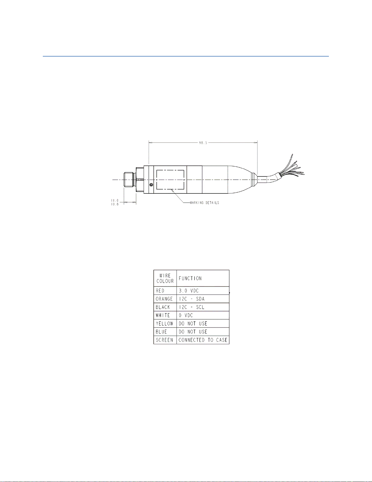
containing information about the device and its environment. The electrical
connections to the sensor are shown in the table below:
The memory map is split into three groups: The volatile information,
configuration parameters and a Flash memory block. The full layout of the
memory is described in the table in section 3.
The I²C address of the supplied sensor has been pre-set to 2. This can be
changed over the bus if required.
2.1 READING FROM THE DEVICE
In order to read from the device the host must first send the address of the
sensor to read, followed by the single byte address of the location to read
Page 2

from the sensor’s memory. The host should then read the four bytes from that
location.
For example, to read the status register from sensor 2 the host should follow
the steps below.
Write 0 (location of the status word) to I2C device 2.
Read four bytes. This will return the 32 bit integer status register, LSB first. The
contents of this register are explained in section 0.
2.2 WRITING TO THE DEVICE
In order to access the device the host must first address the sensor and then
send the address of the location it wants to access followed by the data to be
written to the location.
For example, to write to the access word (location 5) of sensor 2 the host
should follow the steps below.
Write 5 to I2C device 2.
Write the four byte integer, LSB first, to the sensor.
2.3 READING THE COMPENSATED PRESSURE AND TEMPERATURE
When the sensor is first switched on it takes a pressure and temperature
reading. It will not take another reading until instructed to do so by the host. If
the sensor is used in an application where it is only turned on when a reading
is needed and turned off when this reading has been read, this may be
adequate, in other cases the host will need to trigger a reading when required.
To trigger a pressure reading, bit 0 of the status register should be set. The
sensor will now clear that bit and begin taking a reading. This will typically
take approximately 25ms. This host should poll the status register waiting for
bit 0 to be set again. This indicates that the reading is available now. The host
can now read locations 1 and 2 to obtain the compensated pressure and
temperature values.
For example, to trigger a new reading and get the values from sensor 2 the
host should follow the steps below.
Trigger a reading.
Write 0 to I2C device 2.
Write 1 as a four byte integer, LSB first, to the sensor.
Poll the sensor until a reading has been completed.
Write 0 to I2C device 2.
Read the four byte integer, LSB first and check bit 0. If 1, a reading has been
taken. Otherwise, poll again.
Page 3

Read the compensated pressure value.
Address
Type
Name
Volatile?
Description
0
uint32
Status
Y
Status Word. Shows various
aspects of the sensors operation
including Reading available,
pressure valid, and temperature
valid. Also used to start a new
conversion.
1
Float
Compensated
Pressure
Y
Pressure reading in bar
2
Float
Compensated
Temperature
Y
Temperature reading in ºC
5
uint32
Access Word
Y
The access word is used to enable
writing of permanent information.
66
uchar
I²C Address
-
The address of the sensor on the
bus.
77
uint32
Serial Number
-
The serial number of the sensor
79
uint32
Version
-
Software version. nn.nn.nn.nn
128
Float
K00
-
Coefficients (IEEE Float)
129
Float
K01
-
Coefficients (IEEE Float)
130
Float
K02
-
Coefficients (IEEE Float)
131
Float
K03
-
Coefficients (IEEE Float)
132
Float
K04
-
Coefficients (IEEE Float)
133
Float
K10
-
Coefficients (IEEE Float)
134
Float
K11
-
Coefficients (IEEE Float)
135
Float
K12
-
Coefficients (IEEE Float)
136
Float
K13
-
Coefficients (IEEE Float)
137
Float
K14
-
Coefficients (IEEE Float)
138
Float
K20
-
Coefficients (IEEE Float)
139
Float
K21
-
Coefficients (IEEE Float)
140
Float
K22
-
Coefficients (IEEE Float)
141
Float
K23
-
Coefficients (IEEE Float)
142
Float
K24
-
Coefficients (IEEE Float)
Write 1 to I2C device 2.
Read the four byte floating point number.
Read the compensated temperature value.
Write 2 to I2C device 2.
Read the four byte floating point number.
3 MEMORY LAYOUT
Memory Layout is described in the table below.
Page 4

143
Float
K30
-
Coefficients (IEEE Float)
144
Float
K31
-
Coefficients (IEEE Float)
145
Float
K32
-
Coefficients (IEEE Float)
146
Float
K33
-
Coefficients (IEEE Float)
147
Float
K34
-
Coefficients (IEEE Float)
7 6 5 4 3 2 1 0 0
ERASE FLASH
WRITE
ADCPWR
WENAB
TVAL
PVAL
CONV
3.1 STATUS (ADDRESS 0)
The status register represents a bit map that reports on the status of the
sensor. It is also used to trigger a new reading.
Bits 31 to 8 are unused.
3.1.1 ERASE FLASH
Erase the upper flash region of memory. This will only work when WENAB is
set.
3.1.2 WRITE
When this bit is set and WENAB is set, the current configuration will be written
to the Flash memory.
3.1.3 ADCPWR.
Read only. The ADC is powered up.
3.1.4 WENAB.
Read only. The sensor is in customer write enable mode.
3.1.5 TVAL.
Read only. The temperature reading is valid i.e. between the min and max
values of the ADC count. In addition, CONV must be 1.
3.1.6 PVAL.
Read only. The pressure reading is valid i.e. between the min and max values
of the ADC count. In addition, CONV must be 1.
3.1.7 CONV.
Read write. When read, a 1 indicates that a reading has been completed.
When 1 is written a new conversion will be started.
Page 5

3.2 COMPENSATED PRESSURE VALUE (ADDRESS 1)
The most recently requested reading of the pressure.
3.3 COMPENSATED TEMPERATURE VALUE (ADDRESS 2)
The most recently requested reading of the temperature.
3.4 ACCESS WORD (ADDRESS 5)
This word controls access permissions to the other locations in the memory
map. Writing the number 4118 to this register will enable writing of the I2C
address.
3.5 I
2
C ADDRESS (ADDRESS 66).
The address used to access the sensor. This has been pre-set as described in
section 2 above. In order to change this value, the correct value should be
written into the access word above, the new address written here and the
WRITE bit set in the status word.
3.6 SERIAL NUMBER (ADDRESS 77)
The sensor’s serial number.
3.7 VERSION (ADDRESS 79)
The version of the software within the sensor. This is held as 4 hex bytes and
gives a value of the form xx.xx.xx.
3.8 COEFFICIENTS (ADDRESSES 128+)
This section of the memory holds the coefficients/compensation data for the
sensor.
 Loading...