

Page 1

Repair Instructions for Babytherm 8000
Table of contents:
1. Mechanical system........................................................................................................... 3
1.1 Trolley ........................................................................................................................... 3
1.2 Column with electrical height adjustment...................................................................... 5
1.3 Base plate for resting surface and accessory rails........................................................ 7
1.4 Socket strip ................................................................................................................... 7
1.5 Resting surface............................................................................................................. 8
1.6 Accessories................................................................................................................. 14
2. Pneumatic system .......................................................................................................... 14
2.1 Extraction.................................................................................................................... 14
3. Heating panel with sensors ............................................................................................ 15
3.1 General information .................................................................................................... 15
3.2 Heating-panel assembly ............................................................................................. 16
3.3 Testing ........................................................................................................................ 18
3.4 Replacement in repair situation .................................................................................. 18
3.5 Testing after replacement ........................................................................................... 19
3.6 Repair information and modification statuses............................................................. 20
4. Mattress heating electronics........................................................................................... 22
4.1 Removal and installation of electronics and components........................................... 22
4.2 Electronics, complete.................................................................................................. 27
4.3 Controller PCB............................................................................................................ 34
4.4 Power PCB ................................................................................................................. 39
4.5 Display PCB................................................................................................................ 52
4.6 Mains switch ............................................................................................................... 55
4.7 Transformer ................................................................................................................ 56
4.8 Keypad........................................................................................................................ 58
4.9 Mains input ................................................................................................................. 64
4.10 Heating and sensor adapters .................................................................................. 66
5. Mattress heating software .............................................................................................. 68
5.1 Software versions ....................................................................................................... 68
5.2 Testing after replacement ........................................................................................... 68
6. Troubleshooting - mattress heating................................................................................ 69
6132.200 Babytherm 8000 Repair Instructions 04.01 Page 1 of 115
Page 2

6.1 General information .................................................................................................... 69
6.2 Usage instructions for DS mode ................................................................................. 70
6.3 Diagnosis mode .......................................................................................................... 72
6.4 Troubleshooting and error list ..................................................................................... 82
6.5 10-minute test ........................................................................................................... 106
7. Radiant heater 600W ................................................................................................... 106
8. List of test equipment and tools.................................................................................... 107
8.1 Primarily for work on electrical components.............................................................. 107
8.2 Primarily for work on mechanical components.......................................................... 107
8.3 Equipment for functional tests .................................................................................. 108
9. File for repair information and unit modification............................................................ 108
9.1 New software version 1.02 (07.94) ......................................................................... 108
9.2 Mounting the mechanics of the resting-surface tilt-mechanism (09.94)................... 109
9.3 Alteration of class type B to BF (12.94) ................................................................... 109
9.4 Additional height adjustment extra high (02.95)....................................................... 115
9.5 Castors of non-height-adjustable units (03.95)........................................................ 115
6132.200 Babytherm 8000 Repair Instructions 04.01 Page 2 of 115
Page 3

1. Mechanical system
1.1 Trolley
The Babytherm 8000 is available with various trolleys:
- Units with no electrical height adjustment:
o Small base plate for heated cot
o Large base plate for intensive-care model or reanimation unit. This
version permits installation of a radiant heater.
- Units with electrical height adjustment
o Small trolley for heated cot
o Large trolley for intensive-care module or reanimation unit. This
version permits installation of a radiant heater.
1.1.1 Trolley for units without height adjustment
The trolley consists of a trolley plate small or large which is keyed to the metal
casing of the column.
This trolley has the following castors:
2 x castor 2M 21 048
2 x locking castor 2M 21 050
The metal ends and the castor attachment points are secured in each case with
caps 2M 20 989.
6132.200 Babytherm 8000 Repair Instructions 04.01 Page 3 of 115
Page 4

1.1.1.1 Removal and installation of castors
- Pull off cap 2M 20 989 upwards.
- Jack up trolley at castor to be removed.
- Attention: Units manufactured in 1995
(ARJx-xxxx) may be equipped with
castors which are additional secured
by a hexagon socket-head screw M6.
In this case, remove screw.
- Knock out castor with hammer (approx.
0.2 - 0.5 kg) and pin punch
- Install in reverse order. Make sure that
circlip is fitted on pin of castor (part of
scope of delivery of castors).
- In the case the castor was secured by a
hexagon socket-head screw, this screw
must be affixed using Loctite 221
(order no. 79 01 966).
- Fit cap
1.1.2 Trolley for units with height adjustment
There are two possibilities:
- Large trolley 2M 21 036
- Short trolley 2M 21 038
These trolleys have the following height adjustments:
- Height adjustment 230V 2M 20 940
- Height adjustment 230V (extra high) 2M 21 174
(must nor be used on the Heated Cot with
the short trolley 2M 21 038)
- Height adjustment 115V 2M 20 946
- Height adjustment 110V (extra high) 2M 21 175
6132.200 Babytherm 8000 Repair Instructions 04.01 Page 4 of 115
Page 5

(must nor be used on the Heated Cot with
the short trolley 2M 21 038)
In each case with the control unit:
o Foot pedals, complete 2M 20 290
These trolleys have the following castors:
- 2 x castor 2M 20 792
- 2 x locking castor 2M 20 794
- The castors are held in position 2M 20 348.
in each case by the caps
1.1.2.1 Removing and installing castors
The castor pins are held in position in the tubular section by the orange caps
2M 20 348, see Fig. from drawing 2M 21 036. The castors can be pressed out of
the tubular section using two screwdrivers.
Important: Do not apply leverage to plastic parts of castors.
Should this not prove possible, cut off orange cap 2M 20 348 at end of tubular
section and press out castor pin from inside.
1.1.3 Replacement in repair situation
Replacement parts are available in line with the spare parts list.
1.2 Column with electrical height adjustment
These trolleys feature the following height adjustments:
- Height adjustment 230V 2M 20 940
- Height adjustment 230V (extra high) 2M 21 174
(must nor be used on the Heated Cot with
the short trolley 2M 21 038)
- Height adjustment 115V 2M 20 946
6132.200 Babytherm 8000 Repair Instructions 04.01 Page 5 of 115
Page 6

- Height adjustment 110V (extra high) 2M 21 175
(must nor be used on the Heated Cot with
the short trolley 2M 21 038)
In each case with the control unit:
o Foot pedals, complete 2M 20 290
1.2.1 Height-adjustment technical data
Height adjustment 230V:
- Dynamic force: 750 N
- Stroke: 295 mm
- Speed: 12 - 15 mm/s
- Voltage: 220 - 240 V / 50/60 Hz
- Current consumption: 2.5A
- Leakage current: < 0.1 mA
- Fuses:
o Temperature switch (self-resetting)
o 2 x fuse DIN 41662 T3.15A 18 15 148
Height adjustment 115V:
- Dynamic force: 750 N
- Stroke: 295 mm
- Speed: 12 - 15 mm/s
- Voltage: 100 - 127 V / 50/60 Hz
- Current consumption: 5 A
- Leakage current: < 0.1 mA
- Fuses:
6132.200 Babytherm 8000 Repair Instructions 04.01 Page 6 of 115
Page 7

o Temperature switch (self-resetting)
o 2 x fuses DIN 41662 T6.3A 18 15 172
1.2.2 Foot pedals, complete 2M 20 290
The height adjustment is controlled by the foot pedal assembly 2M 20 290.
- Foot pedals, complete 2M 20 290
- Connection diagram 2M 20 370
- Wiring harness 2M 20 213
1.2.3 Replacement in repair situation
Replacement parts are available in line with the spare parts list.
1.3 Base plate for resting surface and accessory rails
The resting surface is attached to the base plate. The Babytherm 8000 comes
with various base plates:
- Small base plate and small trolley for heated cot
o Base plate, small (with handles 2M 20 860) 2M 21 148
- Large base plate and large trolley for intensive-care module or reanimation
unit. This version permits installation of a radiant heater.
o Base plate, large (with handles 2M 20 862) 2M 21 146
Caution: Large base plate is never to be installed on small trolley!
1.3.1 Replacement in repair situation
Replacement parts are available in line with the spare list.
1.4 Socket strip
Caution: The 3x earthing-contact socket strip beneath the base plate of the
resting surface is only intended for:
- Babytherm mattress heating
6132.200 Babytherm 8000 Repair Instructions 04.01 Page 7 of 115
Page 8

- Dräger radiant heater RH 600 (not in the USA and Canada)
- Babytherm height adjustment
Other loads are not permitted!
Important: The radiant heater envisaged at the factory is provided with an
inlet connector for non-heating appliances. The appropriate connecting cable
is pulled through the rail on the back.
Important: Retrofitted loads are not to be connected to the socket strip as
otherwise the data on the rating plate will no longer be correct!
Electrical safety is tested by way of the common power cord.
1.4.1 Replacement in repair situation
Replacement parts are available in line with the spare parts list.
1.4.2 Repair information and modification statuses
1.4.2.1 Alteration of class type B to BF (12.94)
The future Standard for mattress heating IEC 601-2-35 (as at 12.94) prescribes
that the resting surface is no longer to be earthed and that class type BF (Body
Floating) must be used. The units are currently being supplied as type B (Body) i.e.
with earthed resting surface. Production of the Babytherm 8000 with mattress
heating is to be switched as of the start of 1995 to class type Typ BF; prior to this
date roughly 300 units will be delivered with the old class type B.
Subsequent alteration from type B to BF is not envisaged.
Power cord for mattress heating control:
This refers to the short internal mains lead 2M 21 220 between the triple socket in
the Babytherm and the mattress heating control.
Type B Type BF
Ferrite 18 34 967 required on cable No longer ferrite on cable. If already
fitted, ferrite need not be removed
Important: A summary of class alteration from type B to BF is given in
Section 9.3. Consult this Section in the event of doubt.
1.5 Resting surface
6132.200 Babytherm 8000 Repair Instructions 04.01 Page 8 of 115
Page 9

1.5.1 General information
The resting-surface assembly consists of the following:
- Resting surface
- Bottom-section tilt mechanism, bolted to base plate
- Mechanical system of tilt mechanism
- 4 corners for holding glass panels
Various side panels can be attached to the resting surface:
- Tall side panels for heated cot or
- Deep side panels for reanimation unit
The resting surface comes with (heated cot) and without (reanimation unit)
mattress heating:
With mattress heating:
- Gel mattress 2M 20 827
The mattress heating panel is only intended for the gel mattress 2M 20 827!
Danger:
The gel mattress 2M 20 827 may only be used in the Babytherm
8000 in conjunction with the resting-surface heater!
The gel mattress 2M 20 827 is not to be used in the Babytherm
4200 and in other heated cots with a heating-panel temperature in
excess of 40 °C ⇒ danger of burns!
Keep sharp objects away from gel mattress ⇒ danger of damage!
Without mattress heating:
- Foam mattress 2M 21 012
- Babytherm 8000 dummy panel 2M 21 067
6132.200 Babytherm 8000 Repair Instructions 04.01 Page 9 of 115
Page 10

(for electronics opening)
- 4 Dummy plugs 14.3 mm 83 02 977
- 2 Dummy plugs 38 mm 2M 21 341
1.5.2 Testing and adjusting resting-surface tilt mechanism
1.5.2.1 Function
The bottom section of the resting-surface tilt mechanism is connected to the base
plate with 4 hexagon socket-head bolts. This section contains the resting surface
with support being provided on one side by rollers and on the other side by teflon
strips as anti-friction bearings. The resting surface is fixed by way of a gear
mechanism in the bottom section and the latch for the mechanical system of the
resting-surface tilt mechanism.
A
H
C
Pulling the lever A presses the latch B downwards out of the gear mechanism C
and the resting surface D can be swivelled out of its basic position by +15° to -20°.
The lever is pulled back again in each case by two springs and the resting surface
thus fixed in position.
1.5.2.1 Checking function in situ
- Presence of and check on the two return springs 83 00 445
⇒ The spring force must be sufficient to reliably return the lever to its
initial position
- Pull out lever A approximately half way (20 mm):
⇒ Resting surface remains fixed in every position
B
D
H
- Pull out lever A to 3/4 of overall distance (30 mm):
⇒ Resting surface can be silently adjusted
6132.200 Babytherm 8000 Repair Instructions 04.01 Page 10 of 115
Page 11

Important: Refer to 1.5.2.2 if resting surface is released too soon or not soon
enough or if it does not reliably engage in every position.
1.5.2.2 Testing and adjustment following removal
- Remove complete resting surface. To do so interrupt mains connection to
electronics assembly or remove the electronics module and screw out the
four hexagon socket-head bolts H.
A
B
H
D
H
C
E
- Visually inspect gear mechanism C in resting-surface section; there must
not be any signs of wear.
- Visually inspect gear mechanism B of latch 2M 20 855 of mechanical
system of resting-surface tilt mechanism. To do so un screw out bolts E and
F. There must not be any signs of wear. Reattach latch. Important: The
bolts E and F are secured with epoxy hardening glue (UHU Plus).
- Visually inspect tilt mechanism: All moveable parts must be greased with
Molykote 55M order no.15 54 093.
G
F
- The 4 teflon sliders must not be greased.
- Presence of and check on the two return springs 83 00 445
⇒ Spring force must be sufficient to reliably return lever to initial
position.
- Pull out lever A approximately half way (20 mm):
6132.200 Babytherm 8000 Repair Instructions 04.01 Page 11 of 115
Page 12

⇒ Resting surface remains fixed in every position.
- Pull out lever A 3/4 of the total distance (30 mm):
⇒ Resting surface can be silently adjusted
- The disengaging/engaging travel of the latch can be adjusted by way of the
screw G at the latch:
o Resting surface is released too early:
Loosen the screw G a few turns. Unscrew the bolts E and F and
apply epoxy hardening glue (UHU Plus, order no. 11 95 255) on their
threads. Screw in the bolts E and F and re-tighten them. Repeat the
test.
o Resting surface is not released too late or is not released properly:
Remove the bolts E and F and screw-in the screw G a few turns.
Apply epoxy hardening glue (UHU Plus, order no. 11 95 255) on the
threads of the bolts E and F. Screw in the bolts E and F and retighten them. Repeat the test.
- Reattach resting surface
- Electrical safety check
6132.200 Babytherm 8000 Repair Instructions 04.01 Page 12 of 115
Page 13

1.5.3 Corners and side panels
1.5.3.1 Testing
The corners and side panels must be checked for reliable closure. If this is not the
case or if there are visible signs of wear, the panel hinges or housing corners are
to be renewed.
1.5.3.1 Removing and installing corners
Knock corners upwards with plastic hammer. Installation involves reverse
procedure.
1.5.3.2 Side-panel hinges
The hinges of the side panels can be renewed; this requires use of the following
spare parts:
- S-set for hinge, left 2M 21 084
- S-set for hinge, right 2M 21 082
A 2 mm bit and a drill are needed for assembly.
1.5.4 Replacement in repair situation
Replacement parts are available in line with the spare parts list.
1.5.5 Testing after replacement
- Check reliable locking of panels
- Visually inspect correct installation of all parts
- Check resting-surface tilt mechanism (see 1.5.2.1)
- If heating or electronics assembly has been removed:
o Electrical safety check
o Functional check (Test time at least 20 minutes)
• Heating function
6132.200 Babytherm 8000 Repair Instructions 04.01 Page 13 of 115
Page 14

• Mains failure alarm
• Data storage with mains failure alarm
• Function of keys
• Function of display elements
• No error messages
1.5.6 Repair information and modification statuses
1.5.6.1 Mounting the mechanics of the resting-surface (9.94) tilt-mechanism
With immediate effect, the mechanics of the resting-surface tilt-mechanism must
be mounted with 4 Spax screws (order no. 12 75 593). Devices already in service
must be retrofitted with this type of screws, see IDM no. 1 and conversion
instructions under "U", Chapter 2.1. The two cylinder head screws of the latch
2M 20 855 and the screw on the control lever must be secured with epoxy
hardening glue (UHU-Plus, order no. 11 95 255).
1.6 Accessories
1.6.1 Cabinet
- Cabinet mount, complete 2M 20 868
- Swivel cabinet 2M 20 638
1.6.2 Rail for resting-surface
- Modification kit rail 2M 21 468
2. Pneumatic system
2.1 Extraction
The extraction is not part of this documentation.
6132.200 Babytherm 8000 Repair Instructions 04.01 Page 14 of 115
Page 15

3. Heating panel with sensors
3.1 General information
The heating panel consists of an aluminium backing plate (6 mm) to which a
heating foil 24V / 120W is bonded and two twin temperature sensors are bolted.
Transformer
Partition of prim./ sec. voltage
HHT Gel Mattress
Aluminium plate 6mm
Heating foil
Temp. Sensors(2x2 NTCs)
Control unit
Power cord
To distinguish between type B and BF the mattress heating control and heating
panel have different plugs for the heating connection:
Type B (old) - 3-pin connector for heating cable,
one cable for protective conductor
Type BF (new) - 2-pin connector for heating cable
As not all parts of the mattress heating are interchangeable, the modified
components have new order numbers. Always pay attention to repair information
when performing repairs.
The heating panel is only intended for the gel mattress 2M 20 827
6132.200 Babytherm 8000 Repair Instructions 04.01 Page 15 of 115
Page 16
Danger:
The gel mattress 2M 20 827 may only be used in the Babytherm 8000 in
conjunction with the resting-surface heater!
The gel mattress 2M 20 827 is not to be used in the Babytherm 4200 and in
other heated cots with a heating-panel temperature in excess of 40 °C ⇒
danger of burns!
Keep sharp objects away from the gel mattress ⇒ danger of damage!
3.2 Heating-panel assembly
The heating panel consists of the following components:
- Backing plate 2M 20 878
- All-round seal for backing plate 2M 20 882
- Foil heating 24V/120W bonded on for type BF 2M 21 509
- Twin temperature sensor 2M 20 859
The sensors are fitted with thermal
conduction paste at the backing-plate
contact surfaces.
The heating panel is secured in position in the cot from underneath with four bolts.
The heating panels for types B and BF have different order numbers.
The following heating-panel parts differ:
Heating panel 2M 20 877 for type B Heating panel 2M 21 510 for type BF
Double temp. sensor 2M 20 859 with
shield connected to sensors.
Identification: No yellow and blue
shrink-down tubing at sensors.
Sensor cannot be converted to type
BF.
Foil heating 2M 20 876 with 3-pin
connector:
- 2 x heating
- Protective conductor
Double temp. sensor 2M 20 859 with
insulated shield on sensor end,
distinguished by sensors with blue and
yellow shrink-down tubing. This sensor
can also be used in type B. Alteration
has already been made on some units
of type B.
Foil heating 2M 21 509 with 2-pin
connector:
- 2 x heating
6132.200 Babytherm 8000 Repair Instructions 04.01 Page 16 of 115
Page 17
Important: In future only the new heating panel 2M 21 510 will be available. The
new heating panel 2M 21 510 for type BF will then have to be converted to type B
in the event of repair. This will involve taking over the protective-conductor cable
connection and 3-pin heating connector from the defective heating panel
2M 20 877. In this case the protective conductor connection is to be laid separately
from the heating cables. To remove the connector, use can be made of the tool
"Extractor for crimp socket 2.6 mm" with the order no. 79 01 120; another
possibility is to make use of ballpoint-pen refills (with metal tube) with a tube ID of
approx. 2.6 mm.
3.2.1 Heating and sensor connections
- Heating for type B:
Pin Color Significance
1 not yellow/green Heating
2 not yellow/green Heating
3 yellow/green Protective conductor
- Heating for type BF:
2 x Heating
- Twin temperature sensor (2 x 2 sensors):
Refer also to drawing, wiring harness, twin temperature sensor 2M 20 875
under "S".
Pin Color Significance Temperature module
1 blue Sensor 1, first half Module 1
2 red Sensor 1, first half Module 1
6 black Sensor 2, first half Module 2
7 white Sensor 2, first half Module 2
4 blue Sensor 1, second half Module 3
5 red Sensor 1, second half Module 3
9 black Sensor 2, second half Module 4
10 white Sensor 2, second half Module 4
There is no preferential position for the two halves on the backing plate.
assignment on
controller PCB
6132.200 Babytherm 8000 Repair Instructions 04.01 Page 17 of 115
Page 18

3.3 Testing
Refer to 3.5
If there is any doupt as to the accuracy of the temperature on the resting surface
perform the following test at a room temperature of 20 to 30 °C:
- Adjust setpoint to 36.0 °C
- Place the point of the fluid temperature probe of the temperature and
humidity set 79 01 148 on the centerof the heating plate such that the point
touches the plate.
- Cover the plate with the gel mattress 2M 20 827
- Cover the gel mattress with the foam mattress 2M 21 102
- If possible cocer the resting surface with the hood 2M 21 030
- Allow the unit to warm up at least 2 hours
- Important: Do not use any additional radiant heater!
- Test value of the reference temperature instrument:
Reading = 36,0 ± 1,0 °C
3.4 Replacement in repair situation
The following spare parts are available for repairs:
For type B:
- Heating-panel assembly 2M 20 877
o Twin temperature sensor 2M 20 859
o Backing-plate seal 2M 20 882
For type BF:
- Heating-panel assembly 2M 21 510
o Twin temperature sensor 2M 20 859
6132.200 Babytherm 8000 Repair Instructions 04.01 Page 18 of 115
Page 19

o Backing-plate seal 2M 20 882
The following heating-panel parts differ:
Heating panel 2M 20 877 for type B Heating panel 2M 21 510 for type BF
Double temp. sensor 2M 20 859 with
shield connected to sensors.
Identification: No yellow and blue
shrink-down tubing at sensors.
Sensor cannot be converted to type
BF.
Foil heating 2M 20 876 with 3-pin
connector:
- 2 x heating
- Protective conductor
Important: In future only the new heating panel 2M 21 510 will be available. The
new heating panel 2M 21 510 for type BF will then have to be converted to type B
in the event of repair. This will involve taking over the protective-conductor cable
connection and 3-pin heating connector from the defective heating panel
2M 20 877. In this case the protective conductor connection is to be laid separately
from the heating cables. To remove the connector, use can be made of the tool
"Extractor for crimp socket 2.6 mm" with the order no. 79 01 120; another
possibility is to make use of ballpoint-pen refills (with metal tube) with a tube ID of
approx. 2.6 mm.
Double temp. sensor 2M 20 859 with
insulated shield on sensor end,
distinguished by sensors with blue and
yellow shrink-down tubing. This sensor
can also be used in type B. Alteration
has already been made on some units
of type B.
Foil heating 2M 21 509 with 2-pin
connector:
- 2 x heating
3.5 Testing after replacement
Assemble unit ready for operation.
- Visual inspection:
o Correct installation of heating panel and seal
o Proper connection of heating to electronics assembly
o Correct installation of electronics assembly
- Functional check (Test duration at least 30 minutes):
o Adjust setpoint to 37.0 °C.
o If setpoint higher than actual value:
⇒ Heating LED flashes
6132.200 Babytherm 8000 Repair Instructions 04.01 Page 19 of 115
Page 20
o Adjust setpoint to 38.0 °C.
o Interrupt mains connection:
⇒ Visual and acoustic mains failure alarm
o Re-establish mains connection:
⇒ Unit continues to operate with setpoint of 38 °C
- Testing in DS mode, see 6.2 if actual value greater than 37 °C:
o Read out all four temperature values in each case in DS mode 6.2.1 -
6.2.4; the permitted deviation between the minimum and maximum
temperature value is 0.4 °C. Important: The displayed value in DS
mode is 1.0 °C higher than the value normally displayed in operation.
- Electrical safety check
3.6 Repair information and modification statuses
3.6.1 Alteration of class type B to BF (12.94)
The future Standard for mattress heating IEC 601-2-35 (as at 12.94) prescribes
that the resting surface is no longer to be earthed and that class type BF (Body
Floating) must be used. The units are currently being supplied as type B (Body) i.e.
with earthed resting surface. Production of the Babytherm 8000 with mattress
heating is to be switched as of the start of 1995 to class type Typ BF; prior to this
date roughly 300 units will be delivered with the old class type B.
Subsequent alteration from type B to BF is not envisaged.
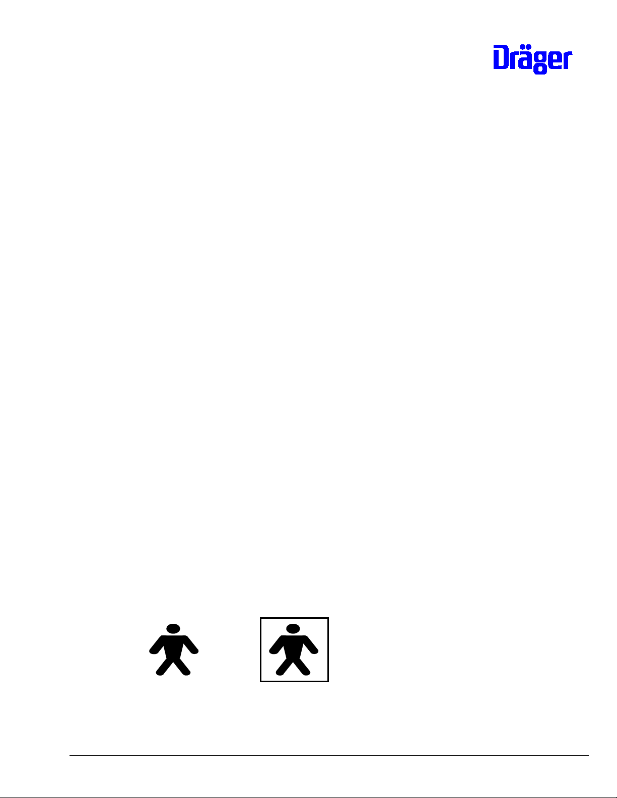
The difference can be seen from the stamp next to the rating plate of the
Babytherm:
Type B: Type BF:
(Figure with no box) (Figure in box)
To distinguish between type B and BF the mattress heating control and heating
panel have different plugs for the heating connection:
6132.200 Babytherm 8000 Repair Instructions 04.01 Page 20 of 115
Page 21
Type B (old) - 3-pin connector for heating cable,
one cable for protective conductor
Type BF (new) - 2-pin connector for heating cable
As not all parts of the mattress heating are interchangeable, the modified
components have new order numbers. Always pay attention to repair information
when performing repairs.
The heating panels for types B and BF have different order numbers.
The following heating-panel parts differ:
Heating panel 2M 20 877 for type B Heating panel 2M 21 510 for type BF
Double temp. sensor 2M 20 859 with
shield connected to sensors.
Identification: No yellow and blue
shrink-down tubing at sensors.
Sensor cannot be converted to type
BF.
Double temp. sensor 2M 20 859 with
insulated shield on sensor end,
distinguished by sensors with blue and
yellow shrink-down tubing. This sensor
can also be used in type B. Alteration
has already been made on some units
of type B.
Foil heating 2M 20 876 with 3-pin
connector:
- 2 x heating
Foil heating 2M 21 509 with 2-pin
connector:
- 2 x heating
- Protective conductor
Important: In future only the new heating panel 2M 21 510 will be available. The
new heating panel 2M 21 510 for type BF will then have to be converted to type B
in the event of repair. This will involve taking over the protective-conductor cable
connection and 3-pin heating connector from the defective heating panel
2M 20 877. In this case the protective conductor connection is to be laid separately
from the heating cables. To remove the connector, use can be made of the tool
"Extractor for crimp socket 2.6 mm" with the order no. 79 01 120; another
possibility is to make use of ballpoint-pen refills (with metal tube) with a tube ID of
approx. 2.6 mm.
Important: A summary of class alteration from type B to BF is given in
Section 9.3. Consult this Section in the event of doubt.
6132.200 Babytherm 8000 Repair Instructions 04.01 Page 21 of 115
Page 22
4. Mattress heating electronics
4.1 Removal and installation of electronics and components
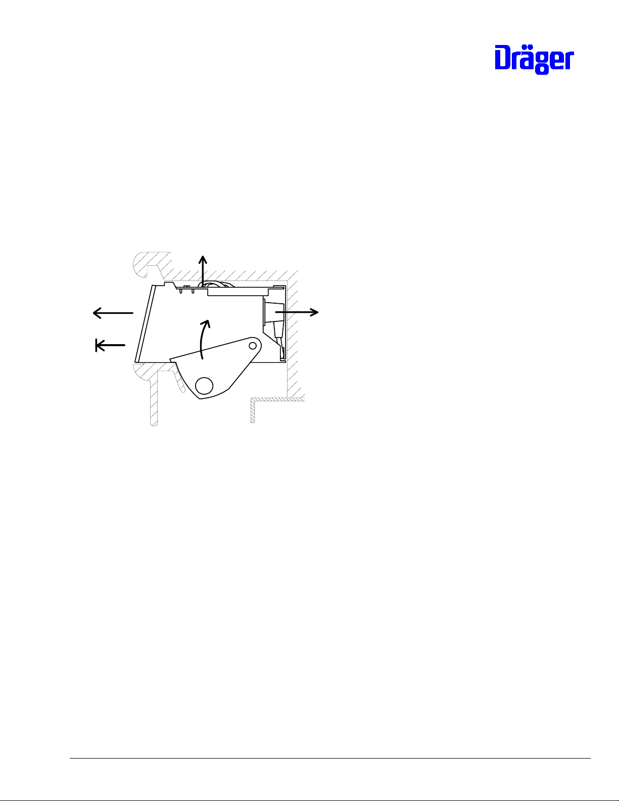
4.1.1 Removing and installing electronics assembly
Important: Components can be effected by static electricity!
- Interrupt mains connection to Babytherm
5.
2.
4.
1. (2x)
- 1. Swing up the two side catches on the
electronics assembly
3.
- 2. Pull electronics assembly slightly out
of Babytherm
- 3. Detach mains connection
- 4. Detach sensor and heating connecting
cable
- 5. Pull out electronics assembly
- Install in reverse order
6132.200 Babytherm 8000 Repair Instructions 04.01 Page 22 of 115
Page 23
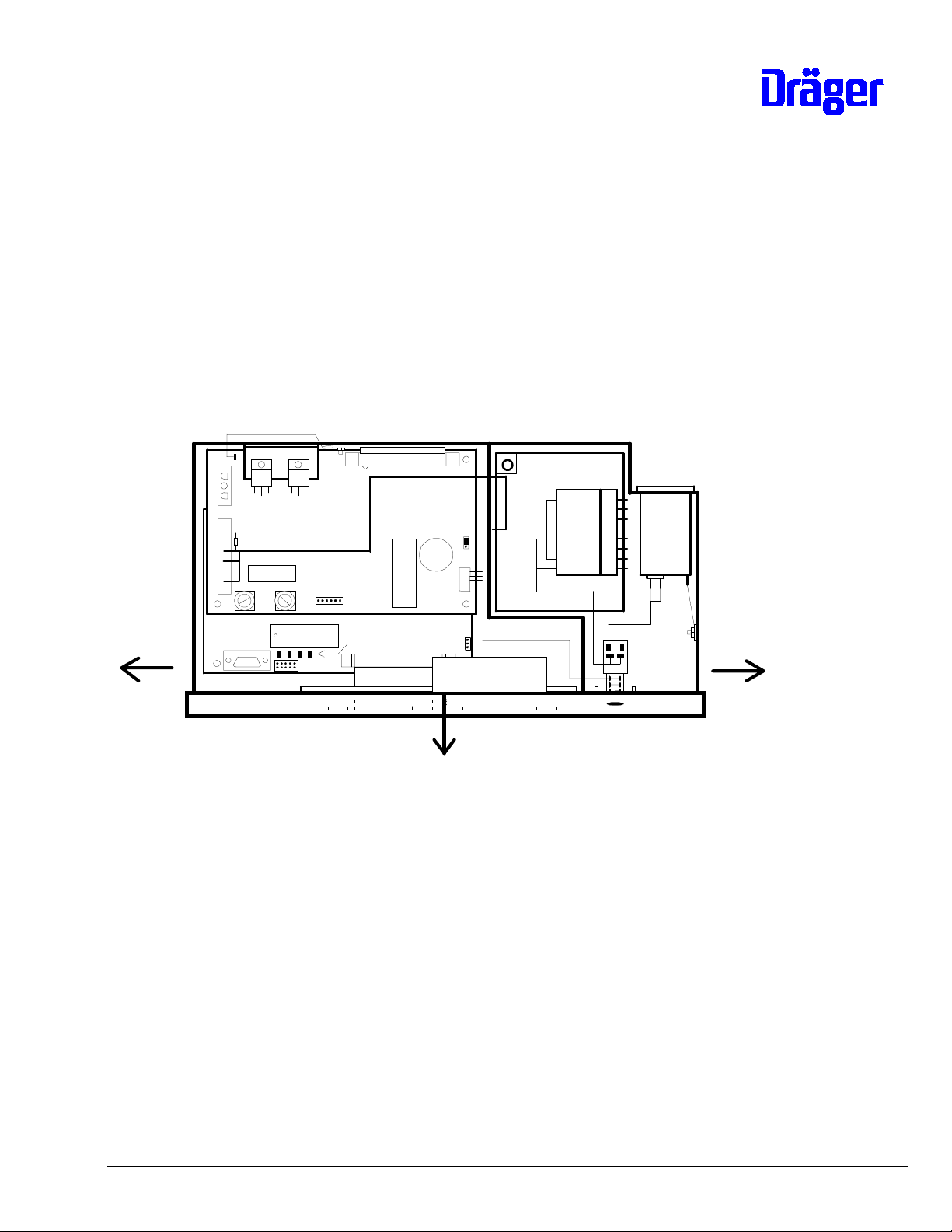
4.1.2 Opening electronics assembly
Important: Components can be effected by static electricity!
- Loosen both screws in the cover of the electronics assembly (do not screw
out); push cover forwards and remove upwards.
- Detach cable connections from connectors in cover to printed circuit cards.
- Bend housing apart on side (1.) and tilt keypad with display PCB forwards
(2.).
Transformer
PCB Power
PCB Controller
1.
1.
Keyboard
2.
- Install in reverse order.
PCB Display
6132.200 Babytherm 8000 Repair Instructions 04.01 Page 23 of 115
Page 24

4.1.3 Wiring diagram
V2 V11
Connection
heating
R22
Relay
Fuses
F2 F1
Connection protective
conductorr PCB Power
+ PCB Controller
Connection
Sensors
RS232
PCB Power
Test points
PCB Controller
EPROM
4 Service-LEDs
Gold Cap
Horn
Mains input with fuses
Transformer
Keyboard
PCB Display
Switch
Important: 100 - 127 V units feature a voltage adapter from the accessory set:
voltage conversion 2M 21 176 between mains switch and transformer.
6132.200 Babytherm 8000 Repair Instructions 04.01 Page 24 of 115
Page 25

4.1.4 Display PCB, keypad and mains switch
Important: Components can be effected by static electricity!
- Remove electronics assembly (see 4.1.1)
- Open electronics assembly (see 4.1.2)
- Detach cable connections to keypad and display PCB (see 4.1.3 wiring
diagram)
- Display PCB is attached to keypad with three nuts
- Mains switch with wiring harness is attached to keypad
- Perform installation in reverse order
4.1.5 Power PCB and controller PCB
Important: Components can be effected by static electricity!
- Remove electronics assembly (see 4.1.1)
- Open electronics assembly (see 4.1.2)
- Detach cable connections to keypad and display PCB, (see 4.1.3 wiring
diagram)
- Power PCB is attached with three snap fasteners and a screw connection
(at the heat sink) whereas controller PCB is secured in position with four
snap fasteners.
o Loosen screw connection for power PCB
o Squeeze snap fastener 1
together and raise printed
circuit card 2; snap fastener
engages again on installation.
o Important: There are two
replacement snap fasteners at
the dividing wall in the
electronics assembly.
1.
2.
o Removal of the controller PCB may involve removal of the snap
fasteners for the power PCB. To do so, squeeze snap fasteners
6132.200 Babytherm 8000 Repair Instructions 04.01 Page 25 of 115
Page 26
together at bottom with pointed pliers and press out fasteners
upwards.
- Install in reverse order
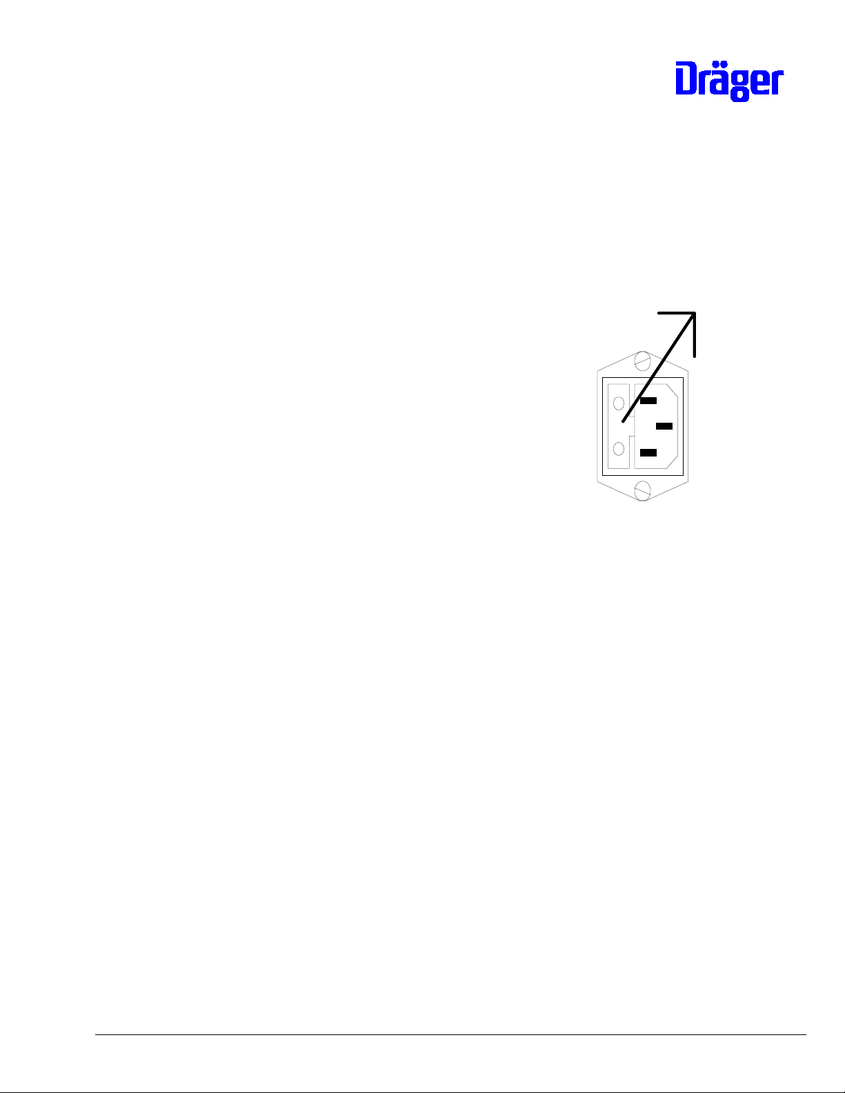
4.1.6 Mains input with mains fuses
4.1.6.1 Mains fuses
- Remove electronics assembly
(see 4.1.1)
- Pull out fuse compartment next
to mains socket.
- Following fuse ratings must be
used:
o 220/240V units:
2 x fuse DIN 41662, T800mA 18 15 075
o 100/127V units:
2 x fuse DIN 41662, T1.6A 18 15 105
- Slide fuse compartment back in again
- Re-install electronics assembly
4.1.6.2 Removing and installing mains input
Important: Components can be effected by static electricity!
- Remove electronics assembly (see 4.1.1)
- Open electronics assembly (see 4.1.2)
- Detach cable connections at mains input (see 4.1.3 wiring diagram)
- Mains input is attached to housing with two screw connections
- Install in reverse order
4.1.7 Transformer, adapter for mains voltage conversion 100 - 127 V
6132.200 Babytherm 8000 Repair Instructions 04.01 Page 26 of 115
Page 27

Important: Components can be effected by static electricity!
- Remove electronics assembly (see 4.1.1)
- Open electronics assembly (see 4.1.2)
- Detach cable connections to transformer (see 4.1.3 wiring diagram)
- 100 - 127 V units feature the voltage adapter 83 06 462 from the accessory
set for voltage conversion 2M 21 176 between mains switch and mains input
of transformer.
- Transformer is attached to housing with four screw connections
- Install in reverse order
4.2 Electronics, complete
4.2.1 General information
The electronics module contains the entire control system for the mattress heating.
The module is made up of the following components:
- Controller PCB
- Power PCB
- Display PCB
- Mains switch
- Transformer
- Keypad
- Mains input
- Adapter for voltage conversion (100/127 V units only)
The repair information for these individual components is given in sections 4.3 -
4.9
4.2.2 Voltage conversion
As the heating is driven via the transformer, the mains voltage is no problem to
convert.
6132.200 Babytherm 8000 Repair Instructions 04.01 Page 27 of 115
Page 28

The following is required for conversion from 220/240V to 100/127V:
- Accessory set, voltage 100/127V 2M 21 176
Important: It is not possible to change the voltage for the optional height
adjustment!
4.2.3 Testing electronics, complete
Assemble unit ready for operation, but do not fix electronics assembly in position in
housing. Connector for attaching sensor cable to unit is therefore accessible.
Switch on unit:
- All displays and horn are actuated for 1.2 s
- Then:
o Setpoint display = 37.0 °C
o Measured value and label "SEt" flash up alternately on actual value
display. Important: measuring range 5 °C - 45 °C.
o Pressing one of the keys " ⇑ " or " ⇓ " setpoint produces constant
actual display.
- Without prior pressing of range expansion key setpoint can be adjusted to
between 35.0 °C and 37.0 °C.
- After prior pressing of range expansion key setpoint can be adjusted in each
case to min 30.0 °C or max. 38.5 °C.
- Adjust setpoint to 37.0 °C.
- Press "check" key:
o All displays and horn are actuated for 2 s.
o All displays and horn then off for 2 s.
o This is followed by return to original display.
- If setpoint higher than actual value:
6132.200 Babytherm 8000 Repair Instructions 04.01 Page 28 of 115
Page 29

o Heating LED flashes
- If actual value is in range between 35.5 °C and 38.0 °C, adjust setpoint in
each case to 1.1 °C higher or lower than actual value:
o Visual and acoustic alarm ± 1 °C
o Acoustic alarm can be suppressed with "horn off" key
- Adjust setpoint to 38.0 °C.
- Interrupt mains connection:
o Visual and acoustic mains failure alarm
- Re-establish mains connection:
o Unit continues to operate with setpoint of 38 °C
- Disconnect plug from sensor cable at assembly:
o Visual and acoustic sensor alarm
- Reconnect plug
- Testing in DS mode, see 6.2, if actual value greater than 37 °C:
o Read out all four temperature values in each case in DS mode 6.2.1 -
6.2.4. The permitted deviation between the minimum and
maximum temperature value is 0.4 °C. Note: The value displayed in
DS mode is 1.0 °C higher than the value normally displayed in
operation.
- Instead of sensors, connect up Babytherm 8000 test plug (35 °C + 1 °C
Offset) 79 00 965.
- Testing in DS mode, see 6.1:
o Read out all four temperature values in each case in DS mode. Test
value is always 35.0 ± 0.2 °C.
- Switch off unit and assemble ready for operation.
- Electrical safety check.
6132.200 Babytherm 8000 Repair Instructions 04.01 Page 29 of 115
Page 30

4.2.4 Replacement in repair situation
If a defective assembly cannot be repaired by replacing individual components, the
following spare parts are available:
For Type B:
- Electronics assembly 220/240V, complete 2M 20 880
o Conversion set 100/127V 2M 21 176
- Repair/replacement electronics assembly 2M 21 095
220/240V, complete
For Type BF:
- Electronics assembly 220/240V, complete 2M 21 500
o Conversion set 100/127V 2M 21 176
- Repair/replacement electronics assembly 2M 21 506
220/240V, complete
Important: The control system 2M 20 880 and the RAT (repair/replacement) control
system 2M 21 095 for type B will no longer be available in future.
Type BF controls are to be ordered as spare part for the old type B. On installation,
merely the housing cover with the two wiring harnesses (heating adapter and
sensor adapter) is to be taken over from the defective control system. The marking
on the housing of the new control system is to be changed to type B and the order
no. from 2M 21 500 to 2M 20 880.
4.2.5 Testing after replacement
The following tests are to be performed after replacement of the electronics
assembly:
- Visual checks:
o Correct mains voltage set in electronics assembly (see 4.2.3).
- Electrical safety check
- Functional test (Test duration at least 20 minutes)
o Function of heating
6132.200 Babytherm 8000 Repair Instructions 04.01 Page 30 of 115
Page 31

o Mains failure alarm
o Data storage with mains failure alarm
o Function of keys
o Function of display elements
o No error messages
6132.200 Babytherm 8000 Repair Instructions 04.01 Page 31 of 115
Page 32

4.2.6 Repair information and modification statuses
4.2.6.1 Alteration of class type B to BF (12.94)
The future Standard for mattress heating IEC 601-2-35 (as at 12.94) prescribes
that the resting surface is no longer to be earthed and that class type BF (Body
Floating) must be used. The units are currently being supplied as type B (Body) i.e.
with earthed resting surface. Production of the Babytherm 8000 with mattress
heating is to be switched as of the start of 1995 to class type Typ BF; prior to this
date roughly 300 units will be delivered with the old class type B.
Subsequent alteration from type B to BF is not envisaged.
The mattress heating controls 220/240V for types B and BF have different order
numbers.
Type B Type BF
Mattress heating control 2M 20 880
Distinguishing feature:
- 3-pin heating connection
RAT mattress heating control
2M 21 095
Mattress heating control 2M 21 500
Distinguishing features:
- 2-pin heating connection
- Order no. printed on
- Marked "BF"
RAT mattress heating control
2M 21 506
Important: The control system 2M 20 880 and the RAT (repair/replacement) control
system 2M 21 095 for type B will no longer be available in future.
Type BF controls are to be ordered as spare part for the old type B. On installation,
merely the housing cover with the two wiring harnesses (heating adapter and
sensor adapter) is to be taken over from the defective control system. The marking
on the housing of the new control system is to be changed to type B and the order
no. from 2M 21 500 to 2M 20 880.
Wiring diagram/wiring harnesses
There is no change to the cable connections between the PCBs. The only
alteration is to the wiring harnesses (sensor adapter and heating adapter), i.e. the
two cable connections from the cover to the PCBs.
Type B Type BF
Wiring harness
Heating adapter 2M 21 096
3-pin adapter cable without ferrite
between heating connection on
Wiring harness
Heating adapter 2M 21 507
2-pin adapter cable with ferrite
between heating connection on
6132.200 Babytherm 8000 Repair Instructions 04.01 Page 32 of 115
Page 33

housing cover and power PCB. housing cover (2-pin) and power PCB
(3-pin).
Wiring harness
Sensor adapter 2M 21 094
Wiring harness with ferrite 18 31 577
between sensor connection on
housing cover and controller PCB.
Wiring harness
Sensor adapter 2M 21 508
Wiring harness without ferrite
between sensor connection on
housing cover and controller PCB
This cable can also be used in type
BF.
Controller PCB
Use in the type BF requires additional capacitors in the measurement input which
cannot be retrofitted in the field. Retrofitting has already been performed if the
modification number after the order no. is ³ 1.1, i.e. the PCB is marked with
82 90 688 - 1.1 or a higher modification number. Some units of type B already
feature this modification.
Controller PCB 82 90 688 ≤≤≤≤ 1.0 Controller PCB 82 90 688 ≥≥≥≥ 1.1
Only for use in type B. Use in type
Can be used in types B and BF
BF could result in destruction of
measurement input caused by the
influence of voltage peaks
Important: A summary of class alteration from type B to BF is given in
Section 9.3. Consult this Section in the event of doubt.
6132.200 Babytherm 8000 Repair Instructions 04.01 Page 33 of 115
Page 34

4.3 Controller PCB
4.3.1 General information
Important: Components can be effected by static electricity!
Position in electronics system:
Connection protective
ground PCB Power + PCB Controller
V2 V11
Connection heating
PCB Power
R22
Relay
Fuses
F2 F1
Test points
Gold Cap
Horn
Transformer
Mains input with fuses
Connection
Sensors
Keyboard
EPROM
PCB Controller
4 Service-LEDs
Switch
PCB Display
6132.200 Babytherm 8000 Repair Instructions 04.01 Page 34 of 115
Page 35

4.3.2 Controller PCB 82 90 668
Layout:
X2
X12
1
X1
X3
Connection
M1
M2
M3
M4
M5
M6
D2 EPROM
RS232
T1
D1
PCB Controller
4 Service-LEDs
X11
Sensors
Components and jumpers:
Item Component/function
X1 Connection to display PCB
X2 Connection to power PCB
X3 Connection to sensors of heating panel; refer to 3.2.1
for wiring diagram
X11 RS232 (not active)
6132.200 Babytherm 8000 Repair Instructions 04.01 Page 35 of 115
Page 36

Item Component/function
X12 Call-up of service mode without keys
Position in operation without jumper or jumper in park
position 2-3:
X12
1
X1
Call-up of service mode. Short circuit for max.
30 seconds between 1-2:
X12
1
X1
T1 Connection to housing (protective conductor)
D1 Microcontroller 68332 18 37 109
D2 EPROM, see 5. Repair information, software
M1 - M4 Temperature module 83 50 082
M5, M6 Not used
Service LEDs
during switch-on test after swich-on test
EPROM defective
RAM defective
PCB Display INOP
Processor ok
no key pressed = V1 to V3 off
1 key pressed = 1 LED flashes
2 keys pressed = 2 LEDs flash
3 keys pressed = 3 LEDs flash
Processor ok
V1 V2 V3 V4
Important: There are no components on the controller PCB which have to be
replaced at service intervals.
6132.200 Babytherm 8000 Repair Instructions 04.01 Page 36 of 115
Page 37

4.3.3 Testing controller PCB
4.3.3.1 Processor system
Following switch-on no INOP error message; LED V4 must light; refer to table in
4.3.2.
4.3.3.2 Measured value acquisition and heating control
Refer to 4.2.3 Testing of electronics, complete.
4.3.4 Replacement in repair situation
The following spare parts are available for repairs:
- Controller PCB (Babytherm) 82 90 668
o EPROM See 5.
Use in the type BF requires additional capacitors in the measurement input which
cannot be retrofitted in the field. Retrofitting has already been performed if the
modification number after the order no. is ³ 1.1, i.e. the PCB is marked with
82 90 688 - 1.1 or a higher modification number. Some units of type B already
feature this modification.
Controller PCB 82 90 688 ≤≤≤≤ 1.0 Controller PCB 82 90 688 ≥≥≥≥ 1.1
Only for use in type B. Use in type
BF could result in destruction of
measurement input caused by the
influence of voltage peaks
Can be used in types B and BF
4.3.5 Testing after replacement
Refer to 4.2.3 Testing electronics, complete
4.3.6 Repair information and modification statuses
4.3.6.1 Alteration of class type B to BF (12.94)
The future Standard for mattress heating IEC 601-2-35 (as at 12.94) prescribes
that the resting surface is no longer to be earthed and that class type BF (Body
Floating) must be used. The units are currently being supplied as type B (Body) i.e.
with earthed resting surface. Production of the Babytherm 8000 with mattress
heating is to be switched as of the start of 1995 to class type Typ BF; prior to this
date roughly 300 units will be delivered with the old class type B.
6132.200 Babytherm 8000 Repair Instructions 04.01 Page 37 of 115
Page 38

Subsequent alteration from type B to BF is not envisaged.
Use in the type BF requires additional capacitors in the measurement input which
cannot be retrofitted in the field. Retrofitting has already been performed if the
modification number after the order no. is 1.1, i.e. the PCB is marked with
82 90 668 - 1.1 or a higher modification number. Some units of type B already
feature this modification.
Controller PCB 82 90 668 ≤≤≤≤ 1.0 Controller PCB 82 90 668 ≥≥≥≥ 1.1
Only for use in type B. Use in type
BF could result in destruction of
measurement input caused by the
influence of voltage peaks
Important: A summary of class alteration from type B to BF is given in
Section 9.3. Consult this Section in the event of doubt.
Can be used in types B and BF
4.3.6.2 New EEPROM on Controller PCB 04.01
A new EEPROM on the Controller PCB P/N 8290668 requires the new software
version 1.04. If a new Controller PCB is used with the previous software version
error code 15 will be generated.
When replacing the Controller PCB P/N 8290668, software version 1.04 (P/N
2M22467) must be installed.
6132.200 Babytherm 8000 Repair Instructions 04.01 Page 38 of 115
Page 39

4.4 Power PCB
4.4.1 General information
Important: Components can be effected by static electricity!
Position in electronics system:
Connection protective
ground PCB Power + PCB Controller
V2 V11
Connection heating
PCB Power
R22
Horn
Relay
Fuses
F2 F1
Test points
Gold Cap
Transformer
Mains input with fuses
Connection
Sensors
Keyboard
EPROM
PCB Controller
4 Service-LEDs
Switch
PCB Display
6132.200 Babytherm 8000 Repair Instructions 04.01 Page 39 of 115
Page 40

4.4.2 Power PCB 82 90 641
Layout:
T1
X7
1
V2 V11
13
2
13
2
X1
PCB Power
R22
Horn
X2
Relay K1
1
Fuses
F2 F1
Test points
X6
1
C25
+
Components and jumpers:
Item Component/function
X1 Connection to controller PCB
X2 Connection to transformer
X5 Connection to auxiliary contacts in mains
switch
X6 Test points:
1 = GND digital
2 = + 5 V digital
3 = Voltage, gold cap (battery)
4 = not used
5 = not used
6 = not used
X7 Connection, heating:
1 and 2 = Heating
3 = Protective conductor, heating panel
X8
+
X5
1
1
6132.200 Babytherm 8000 Repair Instructions 04.01 Page 40 of 115
Page 41

Item Component/function
X8 Operating position: jumper 3-2
Horn
C25
Test points
X6
1
+
Position without jumper or jumper 1-2 for
"horn off" for service only (absolutely
prohibited in operation!):
Horn
C25
Test points
X6
1
+
X8
1
+
X5
+
X5
X8
1
1
1
T1 Connection to housing (protective conductor)
F1 Fuse T 800 mA DIN 41662 18 15 075
F2 Fuse T 6.3 A DIN 41662 18 15 172
K1 Relay 5V / 8A 18 30 732
V2 Triac 600V / 8A 18 13 951
V11 Voltage regulator 5V 18 09 245
C25 Gold cap 3.3F 18 36 986
Horn Buzzer 18 24 880
Important: There are no components on the power PCB which have to be
replaced at service intervals.
4.4.3 Testing power PCB
4.4.3.1 Supply voltages
Preparation for testing:
1 = In
2 = GNDD
3 = Out
6132.200 Babytherm 8000 Repair Instructions 04.01 Page 41 of 115
Page 42

- Interrupt mains connection to Babytherm
- Remove electronics assembly or pull it out of Babytherm
- Remove cover from electronics assembly
- Heating and sensors do not have to be connected
- Establish mains connection
Caution:
Parts under current (e. g. mains switch) may
be touched by coincidance, therefore use
insulation transformer.
6132.200 Babytherm 8000 Repair Instructions 04.01 Page 42 of 115
Page 43

Test set-up and measurement points:
V2 V11
PCB Power
R22
Transformer
24 V AC
Fuses
F2 F1
EPROM
1
Test points
R0
9 V AC
Fuses
F2
PCB Controller
4 Service-LEDs
PCB Display
F1 = Fuse for 24 V AC - Voltage
F2 = Fuse for 5 V - Voltages
F1
Test points
1
PCB Power
GND digital
+ 5 V digital
Batt.-Volt.
Testing:
6132.200 Babytherm 8000 Repair Instructions 04.01 Page 43 of 115
Page 44

- Switch on unit
What How Test value Possible faults
+ 5 V digital Measure with
multimeter between
test points 2 and 1
(GNDD)
Battery
voltage
Battery
voltage
Measure with
multimeter between
test points 3 and 1
(GNDD) with mains
connection
Measure with
multimeter between
test points 3 and 1
(GNDD) without mains
connection, however
with device switched on
+ 5.0 ± 0.2 VDC
≥ 3.5 VDC
≥ 3.5 VDC
- Mains fuses defective
- Fuse F2 defective
- Voltage regulator defective
- 9 VAC from transformer
defective
- Gold cap C25 defective
- Gold cap C25 not charged
(charging time approx. 15
min), because + 5V
defective
- Charging circuit for gold cap
C25 defective
- Gold cap C25 defective, if
previous test with voltage
supply OK
4.4.3.2 Testing heating actuation, safety relay and heating feedback
Preparation for testing:
- Interrupt mains connection to Babytherm.
- Remove electronics assembly and heating panel with sensors from
Babytherm.
- Remove cover from electronics assembly.
- Interrupt ribbon cable connection between power PCB and controller PCB;
this involves disconnecting power PCB.
- Connect up Uni test board, complete 79 00 610 with 40-pin ribbon cable to
power PCB.
- Connect up heating on power PCB.
- Establish mains connection:
6132.200 Babytherm 8000 Repair Instructions 04.01 Page 44 of 115
Page 45

Test set-up and measurement points:
V2
V11
13
2
Connection
heating
PCB Power
R22
Relay
Horn
F2 F1
EPROM
Test points
2
LP Controller
4 Service-LEDs
IN
3
PCB Display
20
13
Dräger Testboard Uni 79 00 620
OUT
free
40
36
1
5 VD
Heating on
GNDD
Relay on
Feedback heating
39
V
6132.200 Babytherm 8000 Repair Instructions 04.01 Page 45 of 115
Page 46

Testing:
- Connect up multimeter on test board between TP 20 (heating feedback) and
TP 1 (GNDD).
- Switch on unit.
⇒ Horn on (no significance)
⇒ Test voltage V < 1 V (low level = heating off)
- Create short circuit on test board between TP 3 (+ 5 VD) and TP 13 (heating
on).
- Additionally create short circuit on test board between TP 3 (+ 5 VD) and TP
36 (relay on).
⇒ Test voltage V > 4 V (high level = heating on)
- Remove one short circuit in each case.
⇒ Test voltage always V < 1 V (low level)
4.4.3.3 Testing horn, acoustic mains failure alarm and mains-switch auxiliary contacts
Preparation for testing (as for 4.4.3.2, however heating and sensors do not have to
be connected):
- Interrupt mains connection to Babytherm.
- Remove electronics assembly from Babytherm.
- Remove cover from electronics assembly.
- Interrupt ribbon cable connection between power PCB and controller PCB;
this involves disconnecting power PCB.
- Connect up Uni test board complete 79 00 610 with 40-pin ribbon cable to
power PCB.
- Establish mains connection.
6132.200 Babytherm 8000 Repair Instructions 04.01 Page 46 of 115
Page 47

Test set-up and measurement points:
V2 V11
13
2
Connection
heating
PCBPower
R22
Relay
Fuses
Test points
1
Horn
Tastatur
V
EPROM
PCB Controller
4 Service-LEDs
IN
2
1
PCB Display
Dräger Testboard Uni 79 00 620
27
Switch
OUT
free
40
38
37
39
R
R
6132.200 Babytherm 8000 Repair Instructions 04.01 Page 47 of 115
Page 48

Testing:
- Testing mains-switch auxiliary contacts (changeover switch):
Switch
position
Off
On R = 0 Ohms
Resistance
measurement on test
board between TP 1
(GNDD) and TP 37
R = ∞
Resistance
measurement on test
board between TP 1
(GNDD) and TP 38
R = 0 Ohms
R = ∞
- Testing mains-switch auxiliary contacts (on/off switch):
Switch
position
Voltage measurement
between TP 27 on test
Possible faults
board and TP 3 on
power PCB (X6)
Off
V > 3.5 VDC
- Switch defective
- Gold cap C25 defective
- Gold cap C25 not
charged because
+ 5V defective
- Charging circuit for
gold cap C25 defective
On
V ≈ 0 V
- Switch defective
- Testing horn and mains failure recognition:
Prerequisite: Mains-switch auxiliary contacts OK
6132.200 Babytherm 8000 Repair Instructions 04.01 Page 48 of 115
Page 49

Test set-up and measurement points:
V2 V11
13
2
Connection
heating
PCB Power
R22
Relay
Fuses
Test points
1
Horn
EPROM
PCB Controller
4 Service-LEDs
IN
2
3
1
Switch
PCB Display
Dräger Testboard Uni 79 00 620
OUT
free
40
30
35
39
Horn on
Horn off
6132.200 Babytherm 8000 Repair Instructions 04.01 Page 49 of 115
Page 50

- Switch on unit
⇒ Horn on
- Create short circuit on test board between TP 3 (+ 5 VD) and TP 30 (horn
off).
⇒ Horn off
- Interrupt mains connection but do not switch off unit.
⇒ Horn on (delay time due to monoflop)
- Reestablish mains connection
⇒ Horn off
- Additionally create short circuit on test board between TP 3 (+ 5 VD) and TP
35 (horn on ).
⇒ Horn on
4.4.3.4 Testing visual mains failure alarm
Prerequisite: mains-switch auxiliary contacts OK.
- Assemble unit ready for operation
- Create mains connection
- Switch on unit
- Interrupt mains connection
⇒ Visual and acoustic mains failure alarm
4.4.4 Replacement in repair situation
The following spare parts are available for repairs:
- Power PCB, complete (see TSB # 4 or IDM # 5) 82 90 771
o Relay 5V / 8A 18 37 001
o Fuse T 800 mA 18 15 075
6132.200 Babytherm 8000 Repair Instructions 04.01 Page 50 of 115
Page 51

o Fuse T 6.3 A 18 15 172
4.4.5 Testing after replacement
The following checks are to be carried out after performing repairs on the power
PCB or after replacing the power PCB:
- Visual checks:
o Jumper fitted on X8 position 2-3 (see 4.4.2 Layout).
o Correct connection of all cables for power PCB (see 4.1.3 Wiring
diagram).
o Heat sink attached to housing by way of screw connection.
- Electrical safety check
- Functional check (Test duration at least 20 minutes)
o Function of heating
o Mains failure alarm
o Data storage with mains failure alarm
o Function of keys
o Function of display elements
o No error messages
6132.200 Babytherm 8000 Repair Instructions 04.01 Page 51 of 115
Page 52

4.5 Display PCB
4.5.1 General information
Important: Components can be effected by static electricity!
The display PCB contains the 7-segment displays and their actuation systems.
The display PCB likewise actuates the LEDs "40°C", "±1°C", ">37°C/<35°C" and
"horn off" on the keypad in addition to reading in all keys.
4.5.2 Display PCB
Layout:
X1
1
PCB Display
1
Components:
Item Component/function
X1 Connection to controller PCB
X2 Connection to keypad
D1 Keypad and display driver 18 20 877
4.5.3 Testing display PCB
4.5.3.1 Testing read-in of keys
Following successful switch-on test, every actuation of a key is displayed by the
service LEDs on the controller PCB. Important: a jumper on the controller PCB
X12 at position 1-2 (call-up of DS mode without keys) is classed as a key being
pressed (refer also to 4.3.3).
D1
X2
6132.200 Babytherm 8000 Repair Instructions 04.01 Page 52 of 115
Page 53

F2 F1
Keyboard
EPROM
PCB Controller
4 Service-LEDs
PCB Display
4 Service-LEDs on Controller PCB
during switch-on test after swich-on test
EPROM defective
RAM defective
PCB Display INOP
Processor ok
V1 V2 V3 V4
no key pressed = V1 to V3 off
1 key pressed = 1 LED flashes
2 keys pressed = 2 LEDs flash
3 keys pressed = 3 LEDs flash
Processor ok
Refer also to testing of keypad under 4.8.3.2.
4.5.3.2 Testing displays and LEDs in situ
Prerequisite: "Check" key OK (see 4.5.3.1).
Press "Check" key during operation:
⇒ All LEDs (and horn) are actuated for one second; "88.8" appears on the
7-segment displays.
Possible faults:
Display Possible faults
LEDs "40°C", "±1°C", ">37°C/<35°C"
and "horn off" defective (off or flash);
7-segment displays not OK
6132.200 Babytherm 8000 Repair Instructions 04.01 Page 53 of 115
- Display PCB defective
Page 54

LED "40°C", "±1°C", ">37°C/<35°C"
and "horn off" off; 7-segment displays
OK
One - three of the LEDs "40°C", "±
1°C",
">37°C/<35°C", or "horn off" off;
7-segment displays OK
Refer also to testing of keypad LEDs "40°C", "±1°C", ">37°C/<35°C" under 4.8.3.3.
4.5.4 Replacement in repair situation
The following spare parts are available for repairs:
- Display PCB 82 90 611
- Keypad and display driver 18 20 877
4.5.5 Testing after replacement
- Display PCB defective (actuation of
LEDs)
- Keypad defective (cable break in
joint GND of these LEDs)
- Keypad defective (LED or cable
break)
The following tests are to be performed after replacing the keypad:
- Visual checks:
o Display PCB correctly installed
- Electrical safety check
- Functional check:
Test duration at least 20 minutes
o Function of keys
o Function of displays
o Mains failure alarm
o Data storage with mains failure alarm
o No error messages
6132.200 Babytherm 8000 Repair Instructions 04.01 Page 54 of 115
Page 55

4.6 Mains switch
4.6.1 General information
The mains switch consists of four switches:
- 2 on/off switches for mains voltage
- 1 on/off switch for horn actuation in the event of mains failure
- 1 changeover switch for mains failure recognition
4.6.2 Mains switch
For connection of mains switch refer to 4.1.3 Wiring diagram.
4.6.3 Testing of mains switch
4.6.3.1 Testing of mains contacts
Testing is performed by measuring the mains voltage upstream and downstream
of the mains contacts (see 4.1.3 Wiring diagram).
4.6.3.2 Testing of auxiliary contacts
Refer to 4.4.3.3 Power PCB; Testing mains-switch auxiliary contacts
4.6.4 Replacement in repair situation
The following spare parts are available for repairs:
- Wiring harness, mains 220/240V 82 01 795
o Mains switch 83 01 781
o Knob for mains switch 83 02 369
4.6.5 Testing after replacement
The following tests are to be performed after replacing the keypad:
- Visual checks
o Mains switch correctly installed (see also 4.1.3 Wiring diagram)
6132.200 Babytherm 8000 Repair Instructions 04.01 Page 55 of 115
Page 56

- Electrical safety check
- Functional check:
Test duration at least 20 minutes.
o Function of keys
o Function of displays
o Mains failure alarm
o Data storage with mains failure alarm
o No error messages
4.7 Transformer
4.7.1 General information
The transformer uses the mains voltage to generate the AC voltages required for
operation (9 V for electronics and 24 V for resting-surface heating). The
transformer is provided with a thermal release.
4.7.2 Technical data of transformer
- Input, primary:
o 2 x 100 V
o 2 x 120 V
- Output, secondary:
o 24 V / 6.7 A with centre tap 9 V
- Frequency:
o 50 / 60 Hz
Ambient temperature:
o max. 45 °C
Limit temperature:
6132.200 Babytherm 8000 Repair Instructions 04.01 Page 56 of 115
Page 57

o 165 °C under overload condition
Thermo-switch:
o Efen 4257A
4.7.3 Testing of transformer
For testing of output voltages refer to 4.4.3.1 Power PCB, testing of supply
voltages.
Caution:
If the thermal release on the transformer has tripped, a check
is to be made as to whether the heating actuation on the
power PCB only switches through whole sinusoidal waves.
This means that if a sinusoidal wave is commenced with
positive voltage pass, it must be ended with the negative
voltage pass!
Testing is performed by taking measurements with an
oscilloscope instead of a multimeter as described under
4.4.3.2 "Testing triac and triac actuation"; the triac is only to
be actuated for an extremely brief period of time.
The transformer cannot be repaired.
4.7.4 Replacement in repair situation
The following spare part is available for repairs:
- Transformer 82 01 796
4.7.5 Testing after replacement
The following tests are to be performed after replacing the
keypad:
- Visual checks
o Transformer correctly installed (see also 4.1.3 Wiring diagram)
- Test output voltages of transformer
- Electrical safety check
6132.200 Babytherm 8000 Repair Instructions 04.01 Page 57 of 115
Page 58

- Functional check(Test duration at least 20 minutes)
o Function of keys
o Function of displays
o Mains failure alarm
o Data storage with mains failure alarm
• No error messages
4.8 Keypad
4.8.1 General information
The keypad contains:
- 5 touch-sensitive keys
-6 LEDs
6132.200 Babytherm 8000 Repair Instructions 04.01 Page 58 of 115
Page 59

4.8.2 Keypad 2M 20 885
Layout:
L5
S1 S2 S3 S4 S5
S1
1
S2
2
S3
3
S4
4
S5
5
125
L1
L2
L3
L4
L6
11
12
L3
14
15
16
L1
L2
9
17
18
L5
L6
L4
22
23
Components and function:
ComponentFunction
S1
Touch-sensitive key ">37°C/<35°C" read in by display
PCB
S2 Touch-sensitive key "negative setpoint" read in by
display PCB
6132.200 Babytherm 8000 Repair Instructions 04.01 Page 59 of 115
Page 60

S3 Touch-sensitive key "positive setpoint" read in by display
PCB
S4 Touch-sensitive key "horn off" read in by display PCB
S5 Touch-sensitive key "check" read in by display PCB
Component Function
L1 LED "40°C", red, actuated by display PCB
L2
LED "±1°C", red, actuated by display PCB
L3 LED "Inop.", red, actuated by controller PCB
L4 LED "power failure", red, actuated by power PCB
L5
LED ">37°C/<35°C", yellow, actuated by display PCB
L6 LED "horn off", yellow, actuated by display PCB
The keypad cannot be repaired.
6132.200 Babytherm 8000 Repair Instructions 04.01 Page 60 of 115
Page 61

4.8.3 Testing of keypad
4.8.3.1 Testing of keys in situ
Following successful switch-on test, every pressing of a key is indicated by the
service LEDs on the controller PCB. Important: a jumper on the controller PCB
X12 in position 1-2 (call-up of DS mode without keys) is classed as pressing of a
key (see also 4.3.3).
F2 F1
Keyboard
EPROM
PCB Controller
4 Service-LEDs
PCB Display
4 Service-LEDs on Controller PCB
during switch-on test after swich-on test
EPROM defective
RAM defective
PCB Display INOP
Processor ok
V1 V2 V3 V4
no key pressed = V1 to V3 off
1 key pressed = 1 LED flashes
2 keys pressed = 2 LEDs flash
3 keys pressed = 3 LEDs flash
Processor ok
6132.200 Babytherm 8000 Repair Instructions 04.01 Page 61 of 115
Page 62

4.8.3.2 Testing keys with keypad removed
The keys can be ohmically checked at the keypad connector (see layout under
4.8.2).
Switch condition, key Resistance
Key not pressed
Key pressed
R = ∞
R ≤ 100 ohms
4.8.3.3 Testing LEDs in situ
Prerequisite: Key "check" and display PCB OK, see 4.8.3.1.
Press "check" key during operation:
⇒ All LEDs and (horn) are actuated for 1 second; "88.8" appears on the
7-segment displays.
Possible faults:
Display Possible faults
LEDs "40°C", "±1°C", ">37°C/<35°C"
and "horn off " defective (off or flash),
7-segment displays not OK
LED "40°C", "±1°C", ">37°C/<35°C"
and "horn off" off, 7-segment displays
OK
One - three of LEDs "40°C", "±1°C",
">37°C/<35°C" or "horn off" off, 7segment displays OK
LED "horn off" off, horn on - Keypad defective (LED defective
LED "horn off" and horn off - Power PCB defective
LED "Inop." off - Keypad defective (LED defective
- Display PCB defective
- Display PCB defective (actuation of
LEDs)
- Keypad defective (cable break in
joint GND of these LEDs )
- Keypad defective (LED(s) defective
or cable break)
or cable break)
- Actuation transistor on power PCB
defective
or cable break)
- Controller PCB defective (actuation)
6132.200 Babytherm 8000 Repair Instructions 04.01 Page 62 of 115
Page 63

4.8.3.3 Testing LEDs with keypad removed
- Electronics assembly is ready for operation, however cable connection
between display PCB and keypad detached.
- Testing is performed by supplying current from test points 2 "+ 5 V digital"
and 1 "GNDD" on power PCB to contacts of LEDs at keypad connector (see
4.8.2 Layout). Caution: Only current from these test points is permitted since
the test point is safeguarded by a 14 Kohm resistor.
F2
Fus es
F1
Test points
24 V AC
EPR OM
R0
F2
1
GND digital
+ 5 V digital
4 Serv ice-LEDs
9 V AC
Fus es
F1
Test points
1
PCB Controller
PCB Displ ay
F1 = Fuse for 24 V AC - Voltage
F2 = Fuse for 5 V - Voltages
PCB Power
Batt.-Volt.
- Each LED is to be checked individually. The LEDs only light very dimly on
account of the low current; the room may have to be darkened. "+" is fed in
in each case at the anodes of the LEDs (pins 14, 15, 16, 17, 18 or 22).
6132.200 Babytherm 8000 Repair Instructions 04.01 Page 63 of 115
Page 64

4.8.4 Replacement in repair situation
The following spare part is available for repairs:
- Keypad 2M 20 885
4.8.5 Testing after replacement
The following tests are to be performed after replacing the keypad:
- Visual checks
o Keypad and connecting cable correctly installed
- Electrical safety check
- Functional check:
Test duration at least 20 minutes.
o Function of keys
o Function of display elements
o Mains failure alarm
o Data storage with mains failure alarm
o No error messages
4.9 Mains input
4.9.1 General information
The mains-input assembly features the following functions:
- Power cord connector
- Accommodation of both mains fuses
- Mains filter
6132.200 Babytherm 8000 Repair Instructions 04.01 Page 64 of 115
Page 65

4.9.2 Replacement in repair situation
The following spare parts are available for repairs:
- Mains filter (mains input) 18 18 384
o 220/240V units:
2 x fuse DIN 41662, T800mA 18 15 075
o 100/127V units:
2 x fuse DIN 41662, T1.6A 18 15 105
- Euro power cord 2M 21 220
4.9.3 Testing after replacement
The following tests are to be performed after replacing the mains input:
- Visual checks
o Connecting cable correctly installed
- Electrical safety check:
- Functional check (Test duration at least 20 minutes)
o Function of keys
o Function of display elements
o Mains failure alarm
o Data storage with mains failure alarm
o No error messages
6132.200 Babytherm 8000 Repair Instructions 04.01 Page 65 of 115
Page 66

4.10 Heating and sensor adapters
4.10.1 General
The heating and sensor adapters are the two cable connections between the
PCBs and the cover of the mattress heating control.
The adapters differ depending on class type B or BF.
4.10.2 Differences between class type B and BF
Type B Type BF
Wiring harness
Heating adapter 2M 21 096
3-pin adapter cable without ferrite
between heating connection on
housing cover and power PCB.
Wiring harness
Sensor adapter 2M 21 094
Wiring harness with ferrite 18 31 577
between sensor connection on
housing cover and controller PCB.
This cable can also be used in type
BF.
Wiring harness
Heating adapter 2M 21 507
2-pin adapter cable with ferrite
between heating connection on
housing cover (2-pin) and power PCB
(3-pin).
Wiring harness
Sensor adapter 2M 21 508
Wiring harness without ferrite
between sensor connection on
housing cover and controller PCB
4.10.3 Replacement in the event of repair
These components are not envisaged as S-parts.
4.10.4 Repair information and modification statuses
4.10.4.1 Alteration of class type B to BF (12.94)
The future Standard for mattress heating IEC 601-2-35 (as at 12.94) prescribes
that the resting surface is no longer to be earthed and that class type BF (Body
Floating) must be used. The units are currently being supplied as type B (Body) i.e.
with earthed resting surface. Production of the Babytherm 8000 with mattress
heating is to be switched as of the start of 1995 to class type Typ BF; prior to this
date roughly 300 units will be delivered with the old class type B.
Subsequent alteration from type B to BF is not envisaged.
6132.200 Babytherm 8000 Repair Instructions 04.01 Page 66 of 115
Page 67

The mattress heating controls 220/240V for types B and BF have different order
numbers.
Type B Type BF
Mattress heating control 2M 20 880
Distinguishing feature:
- 3-pin heating connection
Mattress heating control 2M 21 500
Distinguishing features:
- 2-pin heating connection
- Order no. printed on
- Marked "BF"
RAT mattress heating control
2M 21 095
RAT mattress heating control
2M 21 506
Important: The control system 2M 20 880 and the RAT (repair/replacement) control
system 2M 21 095 for type B will no longer be available in future.
Type BF controls are to be ordered as spare part for the old type B. On installation,
merely the housing cover with the two wiring harnesses (heating adapter and
sensor adapter) is to be taken over from the defective control system. The marking
on the housing of the new control system is to be changed to type B and the order
no. from 2M 21 500 to 2M 20 880.
There is no change to the cable connections between the PCBs. The only
alteration is to the wiring harnesses (sensor adapter and heating adapter), i.e. the
two cable connections from the cover to the PCBs.
Type B Type BF
Wiring harness
Heating adapter 2M 21 096
3-pin adapter cable without ferrite
between heating connection on
housing cover and power PCB.
Wiring harness
Heating adapter 2M 21 507
2-pin adapter cable with ferrite
between heating connection on
housing cover (2-pin) and power PCB
(3-pin).
Wiring harness
Sensor adapter 2M 21 094
Wiring harness with ferrite 18 31 577
between sensor connection on
housing cover and controller PCB.
Wiring harness
Sensor adapter 2M 21 508
Wiring harness without ferrite
between sensor connection on
housing cover and controller PCB
This cable can also be used in type
BF.
Important: A summary of class alteration from type B to BF is given in
Section 9.3. Consult this Section in the event of doubt.
6132.200 Babytherm 8000 Repair Instructions 04.01 Page 67 of 115
Page 68

5. Mattress heating software
5.1 Software versions
The program is stored in an EPROM on the controller PCB.
Position in electronics system after opening electronics assembly:
Connection protective
ground PCB Power + PCB Controller
V2 V11
Connection heating
PCB Power
R22
Relay
Fuses
F2 F1
Test points
Gold Cap
Horn
Transformer
Mains input with fuses
Connection
Sensors
Keyboard
EPROM
PCB Controller
4 Service-LEDs
The following software is envisaged:
- Software 1.00 / 1.01 mattress heating not allowed
- Software 1.02 mattress heating no longer available
- Software 1.04 mattress heating 2M 22 467
5.2 Testing after replacement
See 4.2, however not including test with Babytherm 8000 test plug.
Switch
PCB Display
6132.200 Babytherm 8000 Repair Instructions 04.01 Page 68 of 115
Page 69

6. Troubleshooting - mattress heating
6.1 General information
The DS mode contains the following functions:
- Error list:
Whenever an error is detected, an error number is stored in an error list
together with the error frequency (max. 15). The error list can be read out
and deleted.
- Diagnosis mode:
The following can be implemented in diagnosis mode:
o Readout and setting of elapsed time meter
o Readout of all A/D converter channels and mono-times
o Actuation of safety relay and heating
- 4 Service LEDs on Controller PCB
o One LED indicates status of processor
o Three LEDs are assigned various functions depending on operating
status
6132.200 Babytherm 8000 Repair Instructions 04.01 Page 69 of 115
Page 70

6.2 Usage instructions for DS mode
6.2.1 Call-up of DS mode
Call-up is possible at all times during operation even with INOP.
There are two possibilities:
- Call-up via keys:
ABC
37°C
35°C
DEF
Press both "Silence" and "negative temp." keys for four seconds during
operation.
- Call-up without keys
Call-up is effected via a short-circuit produced for approximately 1 s for
example by way of a jumper on the controller PCB after the self-test.
Important: Error message after 30 s with sustained short circuit.
Position in normal operation without jumper or jumper in park position 2-3:
X1
Horn
off
Check
X12
1
Call-up of service mode. Short circuit for max. 30 seconds between 1-2:
X12
1
X1
6132.200 Babytherm 8000 Repair Instructions 04.01 Page 70 of 115
Page 71

6.2.2 Error list ⇔⇔⇔⇔ Diagnosis mode switching
The unit is in the error list after calling up DS mode.
The key "<35 °C/>37 °C" can be employed at any time to switch between error list
and diagnosis mode.
6.2.3 Exit from service mode
It is possible to exit from service mode at any time by:
- jointly pressing the keys "horn off" and "negative temp." for more than 2 s
or by
- switching off the unit
6132.200 Babytherm 8000 Repair Instructions 04.01 Page 71 of 115
Page 72

6.3 Diagnosis mode
The scope of the diagnosis mode is as follows:
6.3.0 Mode 0 Output of software version
6.3.1 Mode 1 Readout of temperature channel 1 (Vin0)
6.3.2 Mode 2 Readout of temperature channel 2 (Vin1)
6.3.3 Mode 3 Readout of temperature channel 3 (Vin2)
6.3.4 Mode 4 Readout of temperature channel 4 (Vin3)
6.3.5 Mode 5 Free temperature channel 5 (Vin4)
6.3.6 Mode 6 Free temperature channel 6 (Vin5)
6.3.7 Mode 7 Gold cap voltage (Vin 6)
6.3.8 Mode 8 AD test channel (Vin 7)
6.3.9 Mode 9 Output of watchdog 1 time
6.3.A Mode A Output of watchdog 2 time
6.3.b Mode b Switch-on and switch-off, safety relay
6.3.C Mode C Switch-on and switch-off, heating and readout of
heating status feedback
6.3.d Mode d Position of mains switch
6.3.E Mode E Readout and setting of elapsed time meter
6132.200 Babytherm 8000 Repair Instructions 04.01 Page 72 of 115
Page 73

6.3.0 Mode 0 Output of software version
ABC
37°C
35°C
DEF
Horn
off
Check
F = Mode number 0 flashing
A . B C = Software version
The mode number can be switched with the keys "positive temp." or "negative
temp.".
Back
6.3.1 Mode 1 Readout of temperature channel 1 (Vin0)
Output of temperature channel 1 (Vin0) in °C, testing of excess temperature
"ANASW1" and readout of switching status of excess temperature comparator
(UETEMPQ).
ABC
37°C
35°C
DEF
F = Mode number 1 flashing
A B , C = Temperature in °C without 1.0 °C offset subtracted during
operation
D = Switching status, excess temperature comparator
0 = No excess temperature
1 = Excess temperature detected
Press key "check":
Display A B , C = 41.6 ± 0.2 °C and D = 1
6132.200 Babytherm 8000 Repair Instructions 04.01 Page 73 of 115
Horn
off
Check
Page 74

The mode number can be switched with the keys "positive temp." or "negative
temp.".
Back
6.3.2 Mode 2 Readout of temperature channel 2 (Vin1)
Output of temperature channel 2 (Vin1) in °C.
ABC
37°C
35°C
DEF
Horn
off
Check
F = Mode number 2 flashing
A B , C = Temperature in °C without 1.0 °C offset subtracted during
operation
The mode number can be switched with the keys "positive temp." or "negative
temp.".
Back
6.3.3 Mode 3 Readout of temperature channel 3 (Vin2)
Output of temperature channel 3 (Vin2) in °C, test for excess temperature
"ANASW2" and readout of switching status of excess temperature comparator
(UETEMPQ).
ABC
37°C
35°C
DEF
F = Mode number 3 flashing
A B , C = Temperature in °C without 1.0 °C offset subtracted during
operation
6132.200 Babytherm 8000 Repair Instructions 04.01 Page 74 of 115
Horn
off
Check
Page 75

D = Switching status of excess temperature comparator
0 = No excess temperature
1 = Excess temperature detected
Press key "check":
Display A B , C = 41.6 ± 0.2 °C and D = 1
The mode number can be switched with the keys "positive temp." or "negative
temp.".
Back
6.3.4 Mode 4 Readout of temperature channel 4 (Vin3)
Output of temperature channel 4 (Vin3) in °C.
ABC
37°C
35°C
DEF
Horn
off
Check
F = Mode number 4 flashing
A B , C = Temperature in °C without 1.0 °C offset subtracted during
operation
Mode number can be switched with the keys "positive temp." or "negative temp.".
Back
6132.200 Babytherm 8000 Repair Instructions 04.01 Page 75 of 115
Page 76

6.3.5 Mode 5 Free temperature channel 5 (Vin4)
Optional channel not used at present ⇒ ignore
Mode number can be switched with the keys "positive temp." or "negative temp.".
Back
6.3.6 Mode 6 Free temperature channel 6 (Vin5)
Optional channel not used at present ⇒ ignore.
Mode number can be switched with the keys "positive temp." or "negative temp.".
Back
6.3.7 Mode 7 Gold cap voltage (Vin 6)
Output of gold cap voltage from power PCB measured by controller PCB (Vin6)
and deactivation of charging voltage.
ABC
37°C
35°C
DEF
F = Mode number 7 flashing
A , B C = Gold cap voltage in V
D = Charging voltage yes/no
0 = No charging voltage
1 = Charging voltage present
Gold cap voltage with charging voltage (D = 1):
A ; B C ≥ 3.5 V
Gold cap voltage without charging voltage (D = 0); to do so press key "check":
Horn
off
Check
6132.200 Babytherm 8000 Repair Instructions 04.01 Page 76 of 115
Page 77

A ; B C ≥ 3.5 V
Important: Charging time is approx. 15 minutes.
Mode number can be switched with the keys "positive temp." or "negative temp.".
Back
6.3.8 Mode 8 AD test channel (Vin 7)
Output of voltage, AD test channel (Vin 7).
ABC
37°C
35°C
DEF
Horn
off
Check
F = Mode number 8 flashing
A , B C = Voltage in V, test value = 5.0 ± 0.2 V
This voltage is formed from + 5 V digital, + 5 V analog and the reference voltage
for the A/D converter; it corresponds to the voltage of 0.39 ± 0.02 V at the input of
the A/D converter.
Mode number can be switched with the keys "positive temp." or "negative temp.".
Back
6132.200 Babytherm 8000 Repair Instructions 04.01 Page 77 of 115
Page 78

6.3.9 Mode 9 Output of watchdog 1 time
Output of watchdog 1 time in ms.
ABC
37°C
35°C
DEF
Horn
off
F = Mode number 9 flashing
A B C = Mono-time in ms, set value = 250 ± 3 ms
Mode number can be switched with the keys "positive temp." or "negative temp.".
Back
6.3.A Mode A Output of watchdog 2 time
Output of watchdog 2 time in ms.
ABC
Check
37°C
35°C
DEF
Horn
off
Check
F = Mode number A flashing
A B C = Mono-time in ms, set value = 250 ± 3 ms
Mode number can be switched with the keys "positive temp." or "negative temp.".
Back
6132.200 Babytherm 8000 Repair Instructions 04.01 Page 78 of 115
Page 79

6.3.b Mode b Switch-on and switch-off of safety relay
Mode for switching on and switching off safety relay on power PCB with "check"
key. The switching status is indicated and is retained until exit from diagnosis
mode is executed or until mode 1 or 3 is called up.
ABC
37°C
35°C
DEF
Horn
off
Check
F = Mode number b flashing
A B C = rEL as flag for relay
D = Check-back signal of independent excess temperature
deactivation path 41.6 °C
1 = Relay on (no excess temperature)
0 = Relay off (excess temperature)
The relay can be deactivated with the "check" key by setting excess temperature.
Mode number can be switched with the keys "positive temp." or "negative temp.".
Back
6.3.C Mode C Switch-on and switch-off of heating and readout of heating status feedback
Mode for switching on and switching off heating and readout of heating status
feedback
ABC
37°C
35°C
DEF
F = Mode number C flashing
6132.200 Babytherm 8000 Repair Instructions 04.01 Page 79 of 115
Horn
off
Check
Page 80

A B C = HEA as flag for heater (heating)
D = Request, switching status, heating
0 = Heating off
1 = Heating on
E = Heating feedback
0 = Heating off detected
1 = Heating on detected
The heating can be switched on only in this mode for max. 60 s with the "check"
key. This causes the heating to be clocked (1 s on and 0.5 s off).
Heating test:
- Switch on safety relay in mode b.
- Switch on heating in mode C:
Alternating feedback E = 1 and 0 (in mode C)
Mode number can be switched with the keys "positive temp." or "negative temp.".
Back
6.3.d Mode d Position of mains switch
Readout of position of mains-switch auxiliary contacts for warm/cold-start
recognition.
ABC
37°C
35°C
DEF
F = Mode number d flashing
A B C = P F S as flag for power fail switch
Horn
off
Check
D = Position of mains-switch auxiliary contacts
6132.200 Babytherm 8000 Repair Instructions 04.01 Page 80 of 115
Page 81

0 = Fault on account of off position in operation
1 = Normal on account of on position in operation
Mode number can be switched with the keys "positive temp." or "negative temp.".
Back
6.3.E Mode E Readout and setting of elapsed time meter
Output of operating hours with possibility of adjustment.
ABC
37°C
35°C
DEF
Horn
off
Check
F = Mode number E flashing
A B C D E = Operating hours
Operating hours can be adjusted with keys "horn off" and "check":
Key "horn off" ⇒ Selection of digit A, B, C, D or E
Key "check" ⇒ Change digit
Mode number can be switched with the keys "positive temp." or "negative temp.".
Back
6132.200 Babytherm 8000 Repair Instructions 04.01 Page 81 of 115
Page 82

6.4 Troubleshooting and error list
6.4.1 General information
All errors detected by the system are stored in an error list together with a number
describing the cause and the error frequency.
This results in the troubleshooting procedure described in the following.
6.4.1 Troubleshooting procedure, types of error
The troubleshooting procedure results from the type of error:
- INOP immediately after switch-on
- INOP in self-test
- INOP during operation
- Sensor warning
- Keypad error
- Others
6.4.1.1 INOP immediately after switch-on
Description: Unit switches to INOP immediately after switch-on
Cause: - Operating voltage faulty
- Controller PCB defective
Troubleshooting: - Test voltage supply (see 4.4.3.1)
- Read out service LEDs on controller PCB (see 6.3.3)
- Attempt to read out error list (probably not possible)
6.4.1.2 INOP in self-test
Description: Unit switches to INOP after switch-on in self-test
Cause: Stored in error list or indicated by service LEDs on
controller PCB
Troubleshooting: - Test voltage supply (see 4.4.3.1)
6132.200 Babytherm 8000 Repair Instructions 04.01 Page 82 of 115
Page 83

- Read out service LEDs on controller PCB (see 6.4.2)
- Read out and assess error list
6.4.1.3 INOP during operation
Description: Unit switches to INOP during operation
Cause: Stored in error list
Troubleshooting: Read out and assess error list
6.4.1.4 Sensor warning
Description: Unit switches to INOP during operation
Cause: Stored in error list
Troubleshooting: Read out and assess error list
6.4.1.5 Keypad error
Description: Pressed keys are not recognised
Cause: Keypad or keypad evaluation on display PCB defective
Troubleshooting: Test keypad and keypad evaluation:
6.4.1.6 Others
Description: Faults not covered by the above sections
Cause: Non-monitored functions:
- Via service LEDs on controller PCB (see 6.4.2)
- Test keypad (see 4.7.3.2)
- Displays defective
o Modules for displays behind keypad and
display driver on display PCB defective
- Permanent mains failure
o Power cord not correctly connected
o Mains input fuses defective (see 4.9)
o Fuse F2 for 5V supply on controller PCB
6132.200 Babytherm 8000 Repair Instructions 04.01 Page 83 of 115
Page 84

defective (see 4.4.2)
6132.200 Babytherm 8000 Repair Instructions 04.01 Page 84 of 115
Page 85

6.4.2 Service LEDs
Errors are displayed by the service LEDs on the Controller PCB in line with
operating status:
V2 V11
PCB Power
R22
F2 F1
Transformer
Keyboard
EPROM
PCB Controller
4 Service-LEDs
PCB Display
4 Service-LEDs on Controller PCB
during switch-on test after swich-on test
EPROM defective
RAM defective
PCB Display INOP
Processor ok
no key pressed = V1 to V3 off
1 key pressed = 1 LED flashes
2 keys pressed = 2 LEDs flash
3 keys pressed = 3 LEDs flash
Processor ok
V1 V2 V3 V4
6132.200 Babytherm 8000 Repair Instructions 04.01 Page 85 of 115
Page 86

In switch-on test:
Error Cause, remedy
LED V1 lights Cause:
- EPROM D2 on controller PCB defective
- Controller PCB defective
Remedy:
1) Renew EPROM (see 4.3)
2) If 1) unsuccessful: renew controller PCB (see 4.3)
LED V2 lights Cause:
RAM on controller PCB defective
Remedy:
Renew controller PCB (see 4.3)
LED V3 lights Cause:
- Display PCB defective
- Actuation of display PCB on controller PCB defective
Remedy:
1) Renew display PCB (see 4.5)
2) If 1) unsuccessful: renew controller PCB (see 4.3)
LED V4 off Cause:
- Voltage supply 5V defective
- Processor on controller PCB defective
Remedy:
1) Test voltage supply (see 4.4.3.1)
2) If 1) OK: renew controller PCB (see 4.3)
During the course of operation
Significance,
Cause, remedy
error
LED V4 off Cause:
- Voltage supply 5V defective
- Processor on controller PCB defective
Remedy:
1) Test voltage supply, see 4.4.3.1
2) If 1) OK: renew controller PCB (see 4.3)
LED 1 - 3 Keypad test:
One key pressed:
⇒ Only one LED flashes
Two keys pressed:
⇒ Two LEDs flash
Three or more keys pressed:
⇒ Three LEDs flash
6132.200 Babytherm 8000 Repair Instructions 04.01 Page 86 of 115
Page 87

6.4.3 Error list
All errors detected by the system are stored in an error list together with a number
describing the cause and the error frequency.
ABC
37°C
35°C
DEF
Horn
off
Check
A = F for error
BC = Error number (if present, otherwise "--")
DE = Error frequency (max. 15 displayed)
Error list can be read out in both directions with keys "positive temp." and "negative
temp.".
Error list is deleted by pressing key "horn off" for more than 3 s.
Click on error number for viewing:
Acc Err10 Err11 Err12 Err13
Err14 Err15 Err16 Err17 Err18
Err20 Err21 Err22 Err23 Err24
Err25 Err30 Err31 Err32 Err50
Err51 Err53 Err57 Err58 Err59
Err60 Err61 Err70 Err80 Err81
Err82 Err83 Err84 Err85 Err86
Err87 Err88 Err89 Err90 Err91
Err92 Err93
6132.200 Babytherm 8000 Repair Instructions 04.01 Page 87 of 115
Page 88

Error number Cause, remedy
Acc See also error 25
No failure if the unit was switched off for a longer time.
Back / Err25
10 EPROM D2 on controller PCB defective
Error recognition:
Check sum EPROM incorrect during self-test
Cause:
- EPROM D2 on controller PCB defective
- Controller PCB defective
Remedy:
1) Renew EPROM D2 on controller PCB (see 4.3)
2) If 1) unsuccessful: renew controller PCB
Back
11 EPROM D2 on controller PCB defective
Error recognition:
Check sum EPROM incorrect during operation
Cause:
- EPROM D2 on controller PCB defective
- Controller PCB defective
Remedy:
1) Renew EPROM D2 on controller PCB (see 4.3)
2) If 1) unsuccessful: renew controller PCB (see 4.3)
Back
12 RAM on controller PCB defective
Error recognition:
RAM test in self-test unsuccessful
Cause:
- RAM on controller PCB defective
- Controller PCB defective
Remedy:
Renew controller PCB (see 4.3)
Back
6132.200 Babytherm 8000 Repair Instructions 04.01 Page 88 of 115
Page 89

Error number Cause, remedy
13 Software or RAM error
Error recognition:
Incorrectly stored value in RAM
Cause:
- RAM on controller PCB defective
- Controller PCB defective
- External fault due for example to electrostatic charging
Remedy:
If error has occurred several times, renew controller PCB
(see 4.3)
Back
14 Program run error on controller PCB
Error recognition:
The program checks itself for correct program sequence
Cause:
- Interruption due to other error
- EPROM error
- Controller PCB defective
Remedy:
In the event of no other hard errors as well:
1) Renew EPROM (see 4.3)
2) If 1) unsuccessful: renew controller PCB
Back
15 EEPROM error on controller PCB
Error recognition:
EEPROM test unsuccessful
Cause:
- EEPROM on controller PCB defective
- Controller PCB defective
- Wrong software version, see TSB Babytherm 8000 # 11
Remedy:
Renew controller PCB (see 4.3) or software version.
Back
6132.200 Babytherm 8000 Repair Instructions 04.01 Page 89 of 115
Page 90

Error number Cause, remedy
16 Watchdog on controller PCB defective
Error recognition:
Watchdog time, heating monoflop outside tolerance
Troubleshooting:
See 6.2.9 Diagnosis mode 9
Remedy:
Renew controller PCB (see 4.3)
Back
17 Watchdog on controller PCB defective
Error recognition:
Watchdog time, INOP monoflop outside tolerance
Troubleshooting:
See 6.2.9 Diagnosis mode A
Remedy:
Renew controller PCB (see 4.3)
Back
18 Analog error
Error recognition:
Short in several analog inputs at A/D converter
Troubleshooting:
Readout A/D channels in service mode; see 6.2.1 - 6.2.8.
Remedy:
Renew controller PCB (see 4.3)
Back
20 Temperature measurement on controller PCB defective
Error recognition:
Input of temperature channel 1 (Vin0) is switched to test
resistor 41.6 °C during test; resultant measured value is
outside tolerance.
Troubleshooting:
See 6.2.1 Diagnosis mode 1
Cause:
Controller PCB defective
Remedy:
Renew controller PCB (see 4.3)
Back
6132.200 Babytherm 8000 Repair Instructions 04.01 Page 90 of 115
Page 91

21 Temperature measurement on controller PCB defective
Error recognition:
Input of temperature channel 3 (Vin2) is switched to test
resistor 41.6 °C during test; resultant measured value is
outside tolerance.
Troubleshooting:
See 6.2.3 Diagnosis mode 3
Cause:
Controller PCB defective
Remedy:
Renew controller PCB (see 4.3)
Back
22 Excess temperature comparator on controller PCB
defective
Error recognition:
Input of temperature channel 1(Vin0) is switched to test
resistor 41.6 °C during test, however excess temperature
comparator has not switched.
Troubleshooting:
See 6.2.1 Diagnosis mode 1
Cause:
Controller PCB defective
Remedy:
Renew controller PCB (see 4.3)
Back
23 Excess temperature comparator on controller PCB
defective
Error recognition:
Input of temperature channel 3 (Vin2) is switched to test
resistor 41.6 °C during test, however excess temperature
comparator has not switched.
Troubleshooting:
See 6.2.3 Diagnosis mode 3
Cause:
Controller PCB defective
Remedy:
Renew controller PCB (see 4.3)
Back
6132.200 Babytherm 8000 Repair Instructions 04.01 Page 91 of 115
Page 92

Error number Cause, remedy
24
Reference voltage on controller PCB defective
Error recognition:
The reference voltage is read in on the controller PCB and
is outside the tolerance.
Troubleshooting:
See 6.2.6 Diagnosis mode 6
Cause:
Controller PCB defective
Remedy:
Renew controller PCB (see 4.3)
25
Gold cap voltage defective
Error recognition:
The voltage of the gold cap capacitor on the power PCB is
read in by the controller PCB with charging voltage off.
Troubleshooting:
See 6.2.7 Diagnosis mode 7
Cause:
- Gold cap on power PCB defective
- Charging circuit on power PCB defective
- A/D channel Vin 6 on controller PCB defective
- Activation/deactivation of charging voltage on
controller PCB defective
Remedy:
If all other A/D channels functioning:
1) Renew power PCB (see 4.4)
2) If 1) unsuccessful: renew controller PCB (see 4.3)
Back
Back
6132.200 Babytherm 8000 Repair Instructions 04.01 Page 92 of 115
Page 93

Error number Cause, remedy
30 Safety relay K1 on Power PCB defective
Error recognition:
Relay K1 on Power PCB permanently closed
Troubleshooting:
- In diagnosis mode, see 6.2.A and 6.2.b:
Switch on relay and heating in mode A and b:
⇒ Check-back signal = heating on
Switch off relay in mode A and read out heating check back signal in mode b:
⇒ Check-back signal = heating on = relay defective
⇒ Check-back signal = heating off = relay OK
- Without diagnosis mode:
See 4.4.3.2
Cause:
- Relay K1 on Power PCB defective
- Check-back signal from Power PCB defective
- Read-in of check-back signal on Controller PCB defective
Remedy:
1) Renew Power PCB or Relay K1 on Power PCB (see 4.4)
2) If 1) unsuccessful: renew Controller PCB (see 4.3)
Back
6132.200 Babytherm 8000 Repair Instructions 04.01 Page 93 of 115
Page 94

Error number Cause, remedy
31 Heating cannot be switched off
Error recognition:
Heating cannot be switched off by way of triac or relay on
power PCB.
Cause:
- Relay K1 on power PCB defective
- Relay V2 on power PCB defective
- Actuation of relay or triac on power PCB defective
- Heating status feedback on power PCB defective
- Actuation or read-in of check-back signal on
controller PCB defective
Troubleshooting:
- In diagnosis mode, see 6.2.A and 6.2.b:
Switch on relay and heating in modes A and b:
⇒ Check-back signal = heating on
Switch off relay or triac in each case in modes A and b
and
read out heating check-back signal in mode b:
⇒ Check-back signal = heating on = Relay defective
⇒ Check-back signal = heating off = Relay OK
Without diagnosis mode:
See 4.4.3.2
Remedy:
1) Renew power PCB (see 4.4)
2) If 1) unsuccessful: renew controller PCB (see 4.3)
Back
6132.200 Babytherm 8000 Repair Instructions 04.01 Page 94 of 115
Page 95

Error number Cause, remedy
32 Heating cannot be switched on
Error recognition:
Heating present but cannot be switched on.
Cause:
- Fuse F2 on power PCB defective
- Relay K1 on power PCB defective
- Triac V2 on power PCB defective
- Actuation of relay or triac on power PCB defective
- Heating status feedback on power PCB defective
- Actuation or read-in of check-back signal on
controller PCB defective
Troubleshooting:
- Check Fuse F2 on power PCB
- In diagnosis mode, see 6.2.A and 6.2.b:
Switch on relay and heating in modes A and b:
⇒ Check-back signal = heating on
- Without diagnosis mode:
See 4.4.3.2
Remedy:
1) Renew power PCB (see 4.4)
2) If 1) unsuccessful: renew controller PCB (see 4.3)
Back
50 Keypad and display driver on display PCB defective
Error recognition:
The required display information from the RAM of the
display and keypad driver D1 is read back on the display
PCB during operation.
Cause:
- Display PCB defective
- Controller PCB defective
Remedy:
1) Renew display PCB or D1 on display PCB (see 4.5)
2) If 1) unsuccessful: renew controller PCB (see 4.3)
Back
6132.200 Babytherm 8000 Repair Instructions 04.01 Page 95 of 115
Page 96

Error number Cause, remedy
51 Wrong key
Error recognition:
Recognition of key which is not present.
Cause:
- External fault
- Display PCB defective
Back
53 Service jumper on controller PCB forgotten
Error recognition:
Service jumper on controller PCB in position X12/1-2
recognised as being connected for more than 30 s.
Remedy:
1) Move jumper to park position 2-3.
2) If 1) unsuccessful: renew controller PCB (see 4.3)
Back
57 "Check" key sticking
Error recognition:
Key recognised as having been pressed for more than
30 s.
Cause:
- Key on keypad defective
- Display PCB defective
Remedy:
1) If other keys function: renew keypad (see 4.8)
2) If 1) unsuccessful: renew display PCB (see 4.5)
Back
6132.200 Babytherm 8000 Repair Instructions 04.01 Page 96 of 115
Page 97

Error number Cause, remedy
58 "Horn off" key sticking
Error recognition:
Key recognised as having been pressed for more than
30 s.
Cause:
- Key on keypad defective
- Display PCB defective
Remedy:
1) If other keys function: renew keypad (see 4.8)
2) If 1) unsuccessful: renew display PCB (see 4.5)
Back
59 "Positive temp." key sticking
Error recognition:
Key recognised as pressed for more than 30 s.
Cause:
- Key on keypad defective
- Display PCB defective
Remedy:
1) If other keys function: renew keypad (see 4.8)
2) If 1) unsuccessful: renew display PCB (see 4.5)
Back
60 "Negative temp." key sticking
Error recognition:
Key recognised as pressed for more than 30 s.
Cause:
- Key on keypad defective
- Display PCB defective
Remedy:
1) If other keys function: renew keypad (see 4.8)
2) If 1) unsuccessful: renew display PCB (see 4.5)
Back
6132.200 Babytherm 8000 Repair Instructions 04.01 Page 97 of 115
Page 98

Error number Cause, remedy
61
">>>>37 °C/<<<<35°C" key sticking
Error recognition:
Key recognised as pressed for more than 30 s.
Cause:
- Key on keypad defective
- Display PCB defective
Remedy:
1) If other keys function: renew keypad (see 4.8)
2) If 1) unsuccessful: renew display PCB (see 4.5)
Back
70 Heating not connected or defective
Error recognition:
Heating check-back signal negative.
Cause:
- Heating not connected
- Heating high impedance
- Power PCB defective
Troubleshooting:
- Heating connected?
- Measure heating resistance approx. R = 4.8 ohms
Remedy:
If heating OK, renew power PCB (see 4.4)
Back
6132.200 Babytherm 8000 Repair Instructions 04.01 Page 98 of 115
Page 99

Error number Cause, remedy
80 Temperature sensor defective (high impedance)
Error recognition:
Temperature measured value too low.
Cause:
- Sensor 1, first half, high impedance on account of break
in cable
- Cable connection between controller PCB and connector
on cover of electronics assembly defective
- Temperature measurement on controller PCB defective
(Vin 0)
Troubleshooting:
- Test sensors (see 3.2.1)
- Test controller PCB (see 4.3)
Back
81 Temperature sensor defective (high impedance)
Error recognition:
Temperature measured value too low.
Cause:
- Sensor 2, first half, high impedance on account of break
in cable
- Cable connection between controller PCB and connector
on cover of electronics assembly defective
- Temperature measurement on controller PCB
defective (Vin 1)
Troubleshooting:
- Test sensors (see 3.2.1)
- Test controller PCB (see 4.3)
Back
6132.200 Babytherm 8000 Repair Instructions 04.01 Page 99 of 115
Page 100

Error number Cause, remedy
82 Temperature sensor defective (high impedance)
Error recognition:
Temperature measured value too low.
Cause:
- Sensor 1, second half, high impedance on account of
break in cable
- Cable connection between controller PCB and connector
on cover of electronics assembly defective
- Temperature measurement on controller PCB
defective (Vin 2)
Troubleshooting:
- Test sensors (see 3.2.1)
- Test controller PCB (see 4.3)
Back
83 Temperature sensor defective (high impedance)
Error recognition:
Temperature measured value too low.
Cause:
- Sensor 2, second half, high impedance on account of
break in cable
- Cable connection between controller PCB and connector
on cover of electronics assembly defective
- Temperature measurement on controller PCB
defective (Vin 3)
Troubleshooting:
- Test sensors (see 3.2.1)
- Test controller PCB (see 4.3)
Back
6132.200 Babytherm 8000 Repair Instructions 04.01 Page 100 of 115
 Loading...