


Dometic S1521, S1531, S1621, S1631, S1821 Manual
...
THE MOST COMMON SYSTEM PROBLEMS ASSOCIATED WITH THE S1521, S1531, S1621, S1631, S1821, S1831, RM2607, RM2611, RM2807, RM2811, RM3607, RM3807, RM3662, RM3663, RM3862, RM3863, RM4872 and RM4873 REFRIGERATORS.
|
|
|
SYMPTOM |
CAUSE |
|
1. |
No operation - no panel lights |
Operation |
|
|
DC Volts |
|
|
Fuse |
|
|
Wiring |
|
|
Upper Circuit Board |
|
|
Lower Circuit Board |
2. |
No operation - has panel lights |
Operation |
|
|
DC Volts |
|
|
Thermistor |
|
|
Fuses |
|
|
Upper Circuit board |
|
|
Wiring |
|
|
Lower Circuit Board |
3. |
No AC operation - operates on other mode(s) |
Operation |
|
|
AC Volts |
Fuse
Heating Element
Upper Circuit Board
Wiring
Lower Circuit Board
4.No DC operation - operates on other mode(s)
5.No gas operation - operates on other mode(s)
Operation
DC Volts
Fuse
Heating Element
Upper Circuit Board
Wiring
Lower Circuit Board
Operation
LP Gas
Manual Gas Valve
Igniter
High Voltage Cable
Electrode
Solenoid
Upper Circuit Board
Wiring
Lower Circuit Board
6. |
Insufficient cooling on all mode(s). |
Ventilation |
|
|
Leveling |
Ambient Temperature
Air Leaks
Thermistor
Cooling Unit
Thermistor Adjuster

SYMPTOM
7.Insufficient cooling on AC - cools properly on other mode(s)
8.Insufficient cooling on DC - cools properly on other mode(s)
9.Insufficient cooling on gas - cools properly on other mode(s)
10.Freezes
11.Changes preset mode
12. Check light on
13.Interior light on when door is closed
14.Rapid formation of frost
15.Water on frame
CAUSE
AC Volts
Heating Element
Lower Circuit Board
DC Volts
Heating Element
Wiring
Lower Circuit Board
LP gas Orifice Flue Baffle Flue Tube
Flue Cap (if equipped) Burner
Lower Circuit Board
Thermistor
Thermistor Adjuster
Lower Circuit Board
Upper Circuit Board
Operation
DC Volts
Wiring
Upper Circuit Board
Lower Circuit Board
DC Volts
Wiring
LP Gas
Manual Gas Valve
Solenoid
Orifice
Burner
Lower Circuit Board
Thermocouple
Wiring
Door Switch
Door Position
Food Storage
Interior Liner to Frame
High Humidity
Air Leaks
Interior Liner to Frame High Humidity
Air Leaks
Climate Control Heater
ICE MAKER SECTION
SYMPTOM
16.Ice Maker fails to start.
17.Ice Maker won’t make ice.
18.Keeps making ice and won’t shut off.
19.Not making enough ice.
20.Too much water is coming out.
21.Ejector blade frozen into ice cubes.
22.Unit is hooked-up no water comes in.
23.Ice maker is running but won’t make cubes.
24.Ice maker will not make ice.
CAUSE
Operation
Arm in Up Position
AC Voltage
Water Valve
Ice Maker Cycle
Blades Frozen in Ice
AC Voltage
Water Valve
Ice Maker Cycle
Shut-off arm
Operation
Mold Thermostat
Cube Size
Ice Maker Cycle
Water Fill Adjustment
Water Valve
Water Fill Adjustment
Water Valve
Water
Water Valve
Water
Shut-Off Arm
Mold Thermostat
Hold Switch
Ice Ejector
Mold Heater
Timing Motor

AMES REFRIGERATOR OPERATION
2-WAY DISPLAY PANEL
3-WAY DISPLAY PANEL
MODELS INCLUDE: S1521, S1531, S1621, S1631, S1821, S1831, RM2607, RM2611, RM2807, RM2811
AUTO MODE
When operating in the AUTO mode, the AUTO mode indicator lamp (D) will illuminate. The control system will automatically select between AC and GAS operation with AC having priority over GAS. Either the AC indicator lamp (B) or the GAS indicator lamp (C) will illuminate depending on the energy source selected by the control system. If the control system is operating with AC energy and it then becomes unavailable, the system will automatically switch to GAS. As soon as AC becomes available again, the control will switch back to AC regardless of the status of GAS operation.
GAS MODE
When operating in the GAS mode, the AUTO mode indicator lamp (D) will not be illuminated. This mode provides LP gas operation only. The control system will activate the ignition system and will attempt to light the burner for a period of approximately 45 seconds. If unsuccessful, the CHECK indicator lamp (E) will illuminate and the GAS mode indicator lamp (C) will turn off.
To restart GAS operation, press the main power ON/OFF button (1) to the OFF and then ON position. The control system will attempt a new 45 second ignition sequence. If the refrigerator has not been used for a long time or the LP tanks have just been refilled, air may be trapped in the supply lines. To purge the air from the lines may require resetting the main power ON/OFF button (1) three or four times. If repeated attempts fail to start the LP gas operation, check to make sure that the LP gas
supply tanks are not empty and all manual shutoff valves in the lines are open.
If the control is switched to AC or DC operation while the CHECK indicator lamp is on, it will function properly, but the CHECK indicator lamp will not go off until the main power ON/OFF button is pressed to the OFF then ON position.


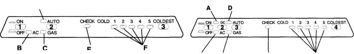


GAS MODE
Move the mode selector button (2) to the UP position. The GAS mode indicator lamp (C) will illuminate. After 45 seconds the burner should be ignited and operating normally.
On the initial refrigerator start-up, it may take longer than 45 seconds to allow air to be purged from the gas line. If the gas does not ignite within 45 seconds, the CHECK indicator lamp (D) will illuminate and the GAS mode indicator lamp (C) will go off.
NOTE: Do not continue to reset GAS operation if the CHECK indicator lamp continues to be illuminated after several tries.
Press the TEMPERATURE SELECTOR button (3) until the lamp at the desired position is illuminated.
TEMPERATURE SELECTOR
The temperature selector on the refrigerator controls both the gas and electric operation, thereby eliminating the necessity of resetting each time a different energy source is employed.
After the initial start-up, the temperature selector should be moved from “COLDEST” to the desired temperature setting, usually about mid-setting.
TO SHUT OFF THE REFRIGERATOR
The refrigerator may be shut off while in any mode of operation by pressing the main power ON/OFF button to the UP (OFF) position. This shuts off all DC power to the refrigerator, including the interior light.
DESCRIPTION OF OPERATING MODES
AUTO MODE
When operating in the AUTO mode, the AUTO mode indicator lamp (B) will illuminate. The control system will automatically select between AC and GAS operation with AC having priority over GAS. Either the AC indicator lamp (A) or the GAS indicator lamp (C) will illuminate depending on the energy source selected by the control system. If the control system is operating with AC energy and it then becomes unavailable, the system will automatically switch to GAS. As soon as AC becomes available again, the control will switch back to AC regardless of the status of GAS operation.
GAS MODE
When operating in the GAS mode, the AUTO mode indicator lamp (B) will be off and the GAS mode indicator lamp (C) will be illuminated. This mode provides LP gas operation only. The control system will activate the ignition system and will attempt to light the burner for a period of approximately 45 seconds. If unsuccessful, the CHECK indicator lamp (D) will illuminate and the GAS mode indicator lamp (C) will turn off.
To restart GAS operation, press the main power ON/OFF button (1) to the OFF and then ON position. The control system will attempt a new 45 second ignition sequence.
If the refrigerator has not been used for a long time or the LP tanks have just been refilled, air may be trapped in the supply lines. To purge the air from the lines may require resetting the main power ON/OFF button (1) three or four times. If repeated attempts fail to start the LP gas operation, check to make sure that the LP gas supply tanks are not empty and all manual shutoff valves in the lines are open.
SPECIAL FEATURES OF OPERATION
This control system contains a feature where it will continue to operate the cooling system in the event of a failure of a major operating component. Two different modes of operation can occur in this category.
If for some reason the display module becomes nonfunctional, the control system will revert to fully automatic operation - selecting the best energy source available with AC and GAS priority. The temperature of the refrigerator will be maintained at the MID position within normal temperature tolerances. The power module will continually attempt to reestablish operation of the display module.
The second standby mode of operation will execute when a failure of the temperature sensing device or associated electronic circuitry occurs. If this should occur, the control system will operate on the energy source selected via the control panel. The cooling unit will run continuously on the selected energy source. The refrigerator will continue to operate in this mode indefinitely or until a new sensor is installed and the system is reset.
ELITE REFRIGERATOR OPERATION (39WAY)
MODELS INCLUDE: RM4873
A 6 C |
D E |
3-WAY PANEL DISPLAY
AES/AUTO MODE
The AES/AUTO mode of operation takes priority over all other operating modes. If more than one mode selector button (2), (3) or (4) is in the down position, the priority is from left to right.
When operating in this mode, the AES/AUTO mode indicator lamp (A) will illuminate. In this mode the control system will automatically select the energy source with AC having top priority, DC second priority and GAS third priority. If the control system has selected a particular energy source such as AC, and then it becomes unavailable, it will automatically seek out the next available energy source.
Press the AES/AUTO mode selector button (2) to the DOWN position. Indicator lamp (A) should illuminate. Indicator lamp (D), (E) or (F) should also illuminate indicating which energy source the control has selected.
Press the TEMPERATURE SELECTOR button (5) until the lamp at the desired position is illuminated.
AC/GAS MODE
Press the AC/GAS mode selector button (3) to the DOWN (ON) position. Mode indicator lamp (B) should illuminate.
In this mode of operation the control system will automatically select between the AC and GAS energy sources with AC having first priority.
The AES/AUTO mode selector button (2) must be in the UP (OFF) position.
Indicator lamp (D) or (E) should also illuminate indicating which energy source the control has selected. If the CHECK indicator lamp (G) illuminates, see GAS MODE for further instructions.
Press the TEMPERATURE SELECTOR button (5) until the lamp at the desired position is illuminated.
10

GAS MODE
When operating in the GAS mode, the AES/AUTO (2) and AC/GAS (3) mode selector buttons must be in the UP (OFF) position.
The GAS mode provides LP gas operation only.
Press the GAS mode indicator button (4) to the DOWN (ON) position.
Indicator lamps (C) and (E) should illuminate indicating GAS operation. After45 seconds the burner should be ignited and operating normally.
On the initial refrigerator start-up, it may take longer than 45 seconds to allow air to be purged from the gas line. If the gas does not ignite within 45 seconds the CHECK indicator lamp (G) will illuminate and the GAS indictor lamp (C) and (E) will go off.
To reset when the CHECK indicator lamp (G) is illuminated, press the main power ON/OFF button (1) to the OFF then ON position.
NOTE: Do not continue to reset GAS operation if the CHECK indicator lamp continues to be illuminated after several tries. If repeated attempts fail to start the LP gas operation, check to make sure that the LP gas supply tanks are not empty and all manual shutoff valves in the lines are open.
Press the TEMPERATURE SELECTOR button (5) until the lamp (H) at the desired position is illuminated.
If the control is switched to the AES/AUTO or AC/GAS mode of operation while the CHECK indicator lamp is on, AC or DC will function properly, but the CHECK indicator lamp will not go off until the main power ON/OFF button is pressed to the OFF then ON position.
TEMPERATURE SELECTOR
The temperature selector on the refrigerator controls both the gas and electric operation, thereby eliminating the necessity of resetting each time a different energy source is employed.
After the initial start-up, the temperature selector should be moved from “COLDEST” to the desired temperature setting, usually about mid-setting.
TO SHUT OFF THE REFRIGERATOR
The refrigerator may be shut off while in any mode of operation by pressing the main power ON/OFF button to the UP (OFF) position. This shuts off all DC power to the refrigerator.
DESCRIPTION OF OPERATING MODES
AES/AUTO MODE
The AES/AUTO mode of operation takes priority over all other operating modes. If more than one mode selector button (2), (3) or (4) is in the down position the priority is from left to right.
When operating in the AES/AUTO mode, the AES/AUTO mode indicator lamp (A) will illuminate. In this mode the control system will automatically select the energy source with AC having top priority, DC second priority and GAS third priority. If the control system has selected a particular energy source such as AC, and then it becomes unavailable, it will automatically seek out the next available energy source.
AC/GAS MODE
When operating in the AC/GAS mode, the AC/GAS mode indicator lamp (B) will illuminate.
In this mode of operation the control system will automatically select between the AC and GAS energy sources with AC having first priority.
11
 Loading...