

D-Link DMS-1100-10TS, DMS-1100-10TP User Manual
User Manual
DMS -1100 Series
L2 2.5 Gigabit Ethernet Switch Series
Rev.A 1


D-Link DMS-1100 Series User Manual
ii
Table of Contents
Table of Contents ............................................................................................................................................. i
About This Guide ............................................................................................................................................. 1
Terms/Usage .................................................................................................................................................. 1
Copyright and Trademarks ............................................................................................................................ 1
1 Product Introduction ................................................................................................................................... 2
DMS-1100-10TS ............................................................................................................................................ 3
Front Panel ................................................................................................................................................. 3
Rear Panel .................................................................................................................................................. 3
DMS-1100-10TP ............................................................................................................................................ 4
Front Panel ................................................................................................................................................. 4
Rear Panel .................................................................................................................................................. 4
DMS-1100 LED Indicators ............................................................................................................................. 5
2 Hardware Installation .................................................................................................................................. 7
Safety Cautions .............................................................................................................................................. 7
Step 1: Unpacking .......................................................................................................................................... 8
Step 2: Switch Installation .............................................................................................................................. 8
Desktop or Shelf Installation ....................................................................................................................... 8
Rack Installation ......................................................................................................................................... 9
Step 3 – Plugging in the AC Power Cord with Power Cord Clip .................................................................... 9
Power Failure ........................................................................................................................................... 12
Grounding the Switch ............................................................................................................................... 12
3 Getting Started ........................................................................................................................................... 13
Management Options ................................................................................................................................... 13
Using Web-based Management .................................................................................................................. 13
Supported Web Browsers ........................................................................................................................ 13
Connecting to the Switch .......................................................................................................................... 13
Login Web-based Management ............................................................................................................... 13
Smart Wizard ............................................................................................................................................... 14
Web-based Management ............................................................................................................................. 14
4 Configuration ............................................................................................................................................. 15
Smart Wizard Configuration ......................................................................................................................... 15
IPv4 Information ....................................................................................................................................... 15
SNMP Settings ......................................................................................................................................... 16
User Accounts Settings ............................................................................................................................ 16
Web-based Management ......................................................................................................................... 17
Tool Bar > Save Menu ................................................................................................................................. 18
Save Configuration ................................................................................................................................... 18
Tool Bar > Tool Menu .................................................................................................................................. 19
Firmware Information................................................................................................................................ 19
Configuration Information ......................................................................................................................... 19
Firmware Upgrade & Backup > Firmware Upgrade from HTTP .............................................................. 19
Firmware Upgrade & Backup > Firmware Upgrade from TFTP ............................................................... 20
Firmware Backup to HTTP & Backup > Firmware Backup to HTTP ........................................................ 20
Firmware Backup to HTTP & Backup > Firmware Backup to TFTP ........................................................ 21
Configuration Upgrade & Backup > Configuration Restore from HTTP ................................................... 21
Configuration Upgrade & Backup > Configuration Restore from TFTP ................................................... 22
Configuration Upgrade & Backup > Configuration Backup to HTTP ....................................................... 22

D-Link DMS-1100DMS-1100 Series User Manual
ii
Configuration Upgrade & Backup > Configuration Backup to TFTP ........................................................ 22
Log Backup > Log Backup to HTTP ......................................................................................................... 23
Log Backup > Log Backup to TFTP ......................................................................................................... 23
Ping .......................................................................................................................................................... 23
Reset ........................................................................................................................................................ 24
Reboot System ......................................................................................................................................... 24
Tool Bar > Smart Wizard .............................................................................................................................. 25
Tool Bar > Online Help ................................................................................................................................. 25
Function Tree ............................................................................................................................................... 27
Device Information.................................................................................................................................... 27
System > System Information .................................................................................................................. 27
System > Port Configuration > Port Settings ........................................................................................... 28
System > Port Configuration > Port Status .............................................................................................. 29
System > Port Configuration > Error Disable Settings ............................................................................. 29
System > Port Configuration > Jumbo Frame .......................................................................................... 30
System > PoE > PoE System (DMS-1100-10TP only) ............................................................................ 31
System > PoE > PoE Status (DMS-1100-10TP only) .............................................................................. 32
System > PoE > PoE Configuration (DMS-1100-10TP only) ................................................................... 32
System > PoE > PoE Measurement (DMS-1100-10TP only) .................................................................. 33
System > System Log > System Log Settings ......................................................................................... 33
System > System Log > System Log Server Settings ............................................................................. 34
System > System Log > System Log ....................................................................................................... 35
System > Time and SNTP > Clock Settings ............................................................................................ 35
System > Time and SNTP > Time Zone Settings .................................................................................... 35
System > Time and SNTP > SNTP Settings ............................................................................................ 37
Management > User Accounts Settings ................................................................................................... 38
Management > Password Encryption ...................................................................................................... 39
Management > SNMP > SNMP Global Settings ...................................................................................... 39
Management > SNMP > SNMP View Table Settings .............................................................................. 40
Management > SNMP > SNMP Community Table Settings .................................................................... 41
Management > SNMP > SNMP Group Table Settings ............................................................................ 42
Management > SNMP > SNMP Engine ID Local Settings ....................................................................... 43
Management > SNMP > SNMP User Table Settings ............................................................................... 43
Management > SNMP > SNMP Host Table Settings ............................................................................... 45
Management > Web ................................................................................................................................. 45
Management > Session Timeout ............................................................................................................. 46
Management > D-Link Discover Protocol Settings................................................................................... 46
L2 Features > FDB > Static FDB > Unicast Static FDB ........................................................................... 47
L2 Features > FDB > Static FDB > Multicast Static FDB ......................................................................... 48
L2 Features > FDB > MAC Address Table Settings ................................................................................ 49
L2 Features > FDB > MAC Address Table .............................................................................................. 50
L2 Features > 802.1Q VLAN .................................................................................................................... 50
L2 Features > Asymmetric VLAN ............................................................................................................. 51
L2 Features > VLAN Interface .................................................................................................................. 51
L2 Features > Auto Surveillance VLAN > Auto Surveillance Properties .................................................. 53
L2 Features > Auto Surveillance VLAN > MAC Settings and Surveillance Device ................................. 54
L2 Features > Voice VLAN > Voice VLAN Global .................................................................................... 55
L2 Features > Voice VLAN > Voice VLAN Port ....................................................................................... 55
L2 Features > Voice VLAN > Voice VLAN OUI ........................................................................................ 56

D-Link DMS-1100 Series User Manual
iii
L2 Features > Voice VLAN > Voice VLAN Device ................................................................................... 57
L2 Features > Voice VLAN > Voice VLAN LLDP-MED Device ................................................................ 57
L2 Features > STP > STP Global Settings .............................................................................................. 57
L2 Features > STP > STP Port Settings .................................................................................................. 59
L2 Features > STP > MST Configuration Identification............................................................................ 61
L2 Features > STP > STP Instance ......................................................................................................... 62
L2 Features > STP > MSTP Port Information .......................................................................................... 62
L2 Features > ERPS(G.8032) > ERPS .................................................................................................... 63
L2 Features > ERPS(G.8032) > ERPS Profile ......................................................................................... 65
L2 Features > Loopback Detection .......................................................................................................... 66
L2 Features > Link Aggregation ............................................................................................................... 67
L2 Features > L2 Multicast Control > IGMP Snooping > IGMP Snooping Settings ................................. 69
L2 Features > L2 Multicast Control > IGMP Snooping > IGMP Snooping Groups Settings .................... 71
L2 Features > L2 Multicast Control > IGMP Snooping > IGMP Snooping Mrouter Settings ................... 72
L2 Features > L2 Multicast Control > IGMP Snooping > IGMP Snooping Statistics Settings ................. 72
L2 Features > L2 Multicast Control > MLD Snooping > MLD Snooping Setting ...................................... 73
L2 Features > L2 Multicast Control > MLD Snooping > MLD Snooping Groups Settings ....................... 75
L2 Features > L2 Multicast Control > MLD Snooping > MLD Snooping Mrouter Settings ...................... 76
L2 Features > L2 Multicast Control > MLD Snooping > MLD Snooping Statistics Settings .................... 77
L2 Features > LLDP > LLDP Global Settings .......................................................................................... 78
L2 Features > LLDP > LLDP Port Settings .............................................................................................. 79
L2 Features > LLDP > LLDP Management Address List ......................................................................... 80
L2 Features > LLDP > LLDP Basic TLVs Settings ................................................................................... 81
L2 Features > LLDP > LLDP Dot1 TLVs Settings .................................................................................... 82
L2 Features > LLDP > LLDP Dot3 TLVs Settings .................................................................................... 82
L2 Features > LLDP > LLDP-MED Port Settings ..................................................................................... 84
L2 Features > LLDP > LLDP Statistics Information ................................................................................. 84
L2 Features > LLDP > LLDP Local Port Information ................................................................................ 86
L2 Features > LLDP > LLDP Neighbor Port Information.......................................................................... 87
L3 Features > IPv4 Interface .................................................................................................................... 87
L3 Features > IPv4 Default Gateway ....................................................................................................... 89
L3 Features > IPv6 Interface .................................................................................................................... 89
L3 Features > IPv6 Default Gateway ....................................................................................................... 90
QoS > Port Default CoS ........................................................................................................................... 91
QoS > Port Scheduler Method ................................................................................................................. 91
QoS > Queue Settings ............................................................................................................................. 92
QoS > CoS to Queue Mapping ................................................................................................................ 93
QoS > Port Rate Limiting .......................................................................................................................... 93
Security > Safeguard Engine.................................................................................................................... 94
Security > Trusted Host ............................................................................................................................ 94
Security > Traffic Segmentation Settings ................................................................................................. 95
Security > Storm Control Settings ............................................................................................................ 95
Security > DoS Attack Prevention Settings .............................................................................................. 97
Security > SSL > SSL Global Setting ....................................................................................................... 97
Security > SSL > SSL Service Policy ....................................................................................................... 98
OAM > Cable Diagnostics ........................................................................................................................ 99
Monitoring > Statistics > Port ................................................................................................................... 99
Monitoring > Statistics > Port Counters .................................................................................................. 100
Monitoring > Statistics > Counters ......................................................................................................... 102

D-Link DMS-1100DMS-1100 Series User Manual
iv
Monitoring > Mirror Settings ................................................................................................................... 103
Green > Power Saving ........................................................................................................................... 104
Green > EEE .......................................................................................................................................... 104
Appendix A - Technical Specifications ..................................................................................................... 106
Hardware Specifications ............................................................................................................................ 106
Features ..................................................................................................................................................... 108
L2 Features ............................................................................................................................................ 108
L3 Features ............................................................................................................................................ 108
VLAN ...................................................................................................................................................... 108
QoS (Quality of Service) ......................................................................................................................... 108
Security ................................................................................................................................................... 108
OAM ....................................................................................................................................................... 108
Management ........................................................................................................................................... 108
D-Link Green Technology ...................................................................................................................... 108
Appendix B – Rack mount Instructions .................................................................................................... 109

D-Link DMS-1100 Series User Manual
1
About This Guide
This guide provides installation and instructions for the D-Link 2.5 Gigabit Ethernet L2 Switch (DMS-110010TS and DMS-1100-10TP).
Note: The model you have purchased may
appear slightly different from the illustrations
shown in the document. Refer to the sections for
detailed information about your switch, its
components, network connections, and technical
specifications.
This guide is divided into four parts:
1. Hardware Installation: Step-by-step hardware installation procedures.
2. Getting Started: A startup guide for basic switch installation and settings.
3. D-Link Network Assistant: An introduction to the central configuration utility.
4. Configuration: Information about the function descriptions and configuration settings.
Terms/Usage
In this guide, the term “Switch” (first letter capitalized) refers to the DMS-1100 Series switch and “switch”
(first letter lower case) refers to other Ethernet switches. Some technologies use “switch”, “bridge” and
“switching hubs” interchangeably, and all are commonly accepted terms for Ethernet switches.
A NOTE indicates important information that
helps you make better use of the device.
A CAUTION indicates the potential for property
damage or personal injury.
Copyright and Trademarks
Information in this document is subjected to change without notice.
© 2017 D-Link Corporation. All rights reserved.
Reproduction in any manner whatever without the written permission of D-Link Corporation is strictly
forbidden.
Trademarks used in this text: D-Link and the D-LINK logo are trademarks of D-Link Corporation; Microsoft
and Windows are registered trademarks of Microsoft Corporation.
Other trademarks and trade names may be used in this document to refer to either the entities claiming the
marks and names or their products. D-Link Corporation disclaims any proprietary interest in trademarks and
trade names other than its own.

D-Link DMS-1100 Series User Manual
2
1 Product Introduction
Thank you and congratulations on your purchase of D-Link DMS-1100 Series Switch.
D-Link's latest generation L2 2.5 Gigabit Ethernet switch series blends plug-and-play simplicity with
exceptional value and reliability for small and medium-sized business (SMB) networking. All models are
housed in a new style rack-mount metal case with easy-to-view front panel diagnostic LEDs, and provide
advance features including network security, traffic segmentation, QoS and versatile management.
Flexible Port Configurations: The DMS-1100 Series is D-Link’s latest 2.5G switch which provides 8-port
2.5GBASE-T plus 2 SFP+ models. The DMS-1100 Series switches, have the advantage of using intuitive
feature-rich software and utilizing a neat and simplified Web GUI allowing users to access and configure the
Switch from everywhere via a web browser. 2.5GBASE-T provides the requisite backward compatibility that
allows end users to transparently upgrade from 100/1000Mbps to 2.5 Gbps, using Cat 5e, unshielded and
shielded twisted-pair cables. 10G SFP+ has the advantage of lower power consumption, longer cable
distance, and better latency performance. Direct Attach Cables (DACs) can be used to provide a cost
effective way of connecting switches at 10 Gbps that are in close proximity to each other.
D-Link Green Technology: D-Link Green devices aim to provide eco-friendly alternatives without
compromising performance. D-Link Green Technology includes a number of innovations to reduce energy
consumption on DMS-1100 series switches, such as reducing power when a port does not have a device
attached, or adjusting the power usage according to the length of Ethernet cable connected to it.
Extensive Layer 2 Features: Implemented as complete L2 devices, these switches include functions such
as IGMP snooping, port mirroring, Spanning Tree, ERPS, 802.3ad LACP, SNTP, LLDP and Loopback
Detection to enhance performance and network reliability.
QoS: The switches support bandwidth control and 802.1p priority queues, enabling users to run bandwidthsensitive applications such as voice and video on the network. These functions allow the switches to work
seamlessly with VLANs, 802.1p traffic and IPv6 Traffic Class priority to prioritize traffic on the network.
Network Security: D-Link’s innovative Safeguard Engine function protects the switches against traffic
flooding caused by virus attacks. Additional features such as Storm Control can help to keep the network
from being overwhelmed by abnormal traffic. Port Security is another simple but useful authentication
method to maintain the network device integrity.
Versatile Management: The new generation of D-Link 2.5 Gigabit Ethernet Switches provide growing
businesses with a simple and easy management of their network, using a web-based management interface
that allows administrators to remotely control their network down to the port level. Alternatively, the Switch
can also be managed, in-band, by using a Telnet connection to any of the LAN ports on the Switch.
Users can also access the switch via Telnet. Some basic tasks can be performed such as changing the
Switch IP address, resetting the settings to factory defaults, setting the administrator password and rebooting
the Switch.
In addition, users can utilize the SNMP MIB (Management Information Base) to poll the switches for
information about the status, or send out traps of abnormal events. SNMP support allows users to integrate
the switches with other third-party devices for management in an SNMP-enabled environment. D-Link Smart
Managed Switches provides easy-to-use graphic interface and facilitates the operation efficiency.
D-Link DMS-1100 Series User Manual
3
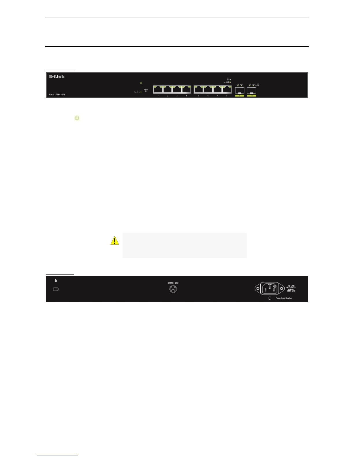
DMS-1100-10TS
8-Port 2.5GBASE-T and 2-Port 10G SFP+ Smart Managed Switch.
Front Panel
Figure 1.1 – DMS-1100-10TS Front Panel
Power LED : The Power LED lights up when the Switch is connected to a power source.
Fan Error: The Fan error LED lights up when the fan has runtime failure and is brought offline.
Reset: Press the Reset button for 1~5 seconds to reboot the device. Press the Reset button for 6~10
seconds to reset the Switch back to the default settings and led will be solid light with amber for 2 seconds.
Or press the Reset button over 11 seconds to enter the loader mode after device reboot and the led will be
solid light with green for 2 seconds. If the device cannot reboot the Switch, the device will enter the loader
mode automatically.
Port Link/Act/Speed LED (1-8): The port LEDs indicate a network link through the corresponding port.
Blinking indicates the Switch is either sending or receiving data to the port. When the port LED glows amber,
it indicates the port is running at 100 Mbps or 1000 Mbps. When the port LED glows green, it is running at
2.5 Gbps.
Port Link/Act/Speed LED (9F, 10F): The port LEDs indicate a network link through the corresponding port.
Blinking indicates the Switch is either sending or receiving data to the port. When the port LED glows green,
it is running at 1000 Mbps or 10 Gbps.
CAUTION: The MiniGBIC ports should use UL
listed Optical Transceiver product, Rated Laser
Class I. 3.3Vdc
Rear Panel
Figure 1.2 – DMS-1100-10TS Rear Panel
Power: Connect the AC power cord to this port.
D-Link DMS-1100 Series User Manual
4
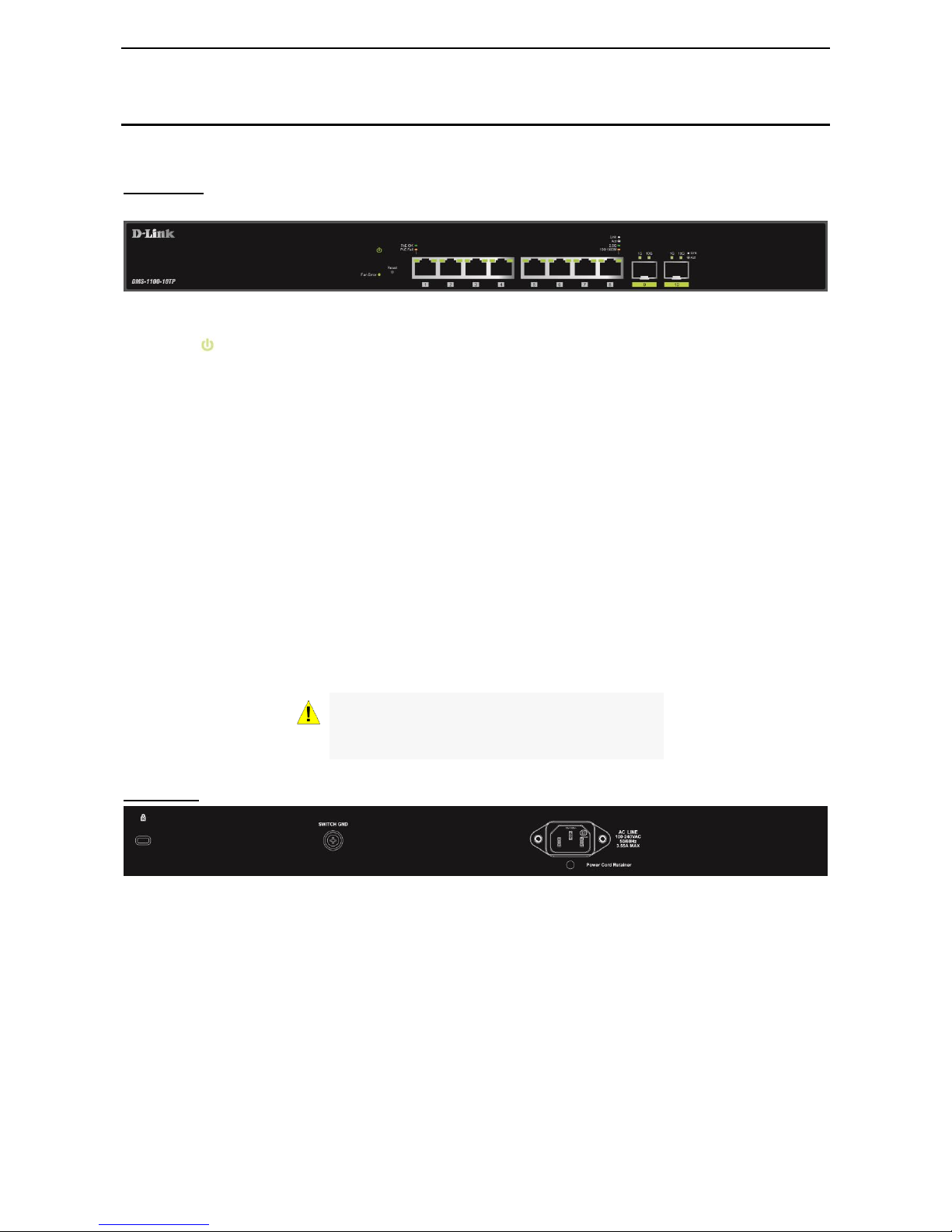
DMS-1100-10TP
8-port 2.5GBASE-T PoE+ and 2-port 10G SFP+ Smart Managed Switch.
Front Panel
Figure 1.3 – DMS-1100-10TP Front Panel
Power LED : The Power LED lights up when the Switch is connected to a power source.
Fan Error: The Fan error LED lights up when the fan has runtime failure and is brought offline.
Reset: Press the Reset button for 1~5 seconds to reboot the device. Press the Reset button for 6~10
seconds to reset the Switch back to the default settings and led will be solid light with amber for 2 seconds.
Or press the Reset button over 11 seconds to enter the loader mode after device reboot and the led will be
solid light with green for 2 seconds. If the device cannot reboot the Switch, the device will enter the loader
mode automatically.
PoE OK/FAIL: The PoE LED shows the status of the PoE ports, the green light (OK) indicates that PoE work
fine and the amber light (Fail) indicate that the PoE is working abnormally.
Port Link/Act/Speed LED (1-8): The port LEDs indicate a network link through the corresponding port.
Blinking indicates the Switch is either sending or receiving data to the port. When the port LED glows amber,
it indicates the port is running at 100 Mbps or 1000 Mbps. When the port LED glows green, it is running at
2.5 Gbps.
Port Link/Act/Speed LED (9F, 10F): The port LEDs indicate a network link through the corresponding port.
Blinking indicates the Switch is either sending or receiving data to the port. When the port LED glows green,
it is running at 1000 Mbps or 10 Gbps.
CAUTION: The MiniGBIC ports should use UL
listed Optical Transceiver product, Rated Laser
Class I. 3.3Vdc.
Rear Panel
Figure 1.4 – DMS-1110-10TP Rear Panel
Power: Connect the AC power cord to this port.

D-Link DMS-1100 Series User Manual
5
DMS-1100 LED Indicators
The Switch supports LED indicators for Power, Fan Error, PoE OK/Fail and Link/Act for each port. The
following shows the LED indicators for the DMS-1100 series Smart Managed Switch along with an
explanation of each indicator.
Figure 1.5 –LED Indicators on DMS-1100 series
Location
LED Indicative
Color
Status
Description
Per Device
Power
Green
Solid Light
Power on.
Light off
Power off.
Fan Error
Red
Solid light
The fan has runtime failure and is
brought offline.
LED Per
2.5GBASE-T
Port
Link/Act/Speed
Green/Amber
Solid Green
When there is a secure 2.5Gbps
connection (or link) at any of the
ports.
Blinking Green
When there is reception or
transmission (i.e. Activity—Act) of
data occurring at any of the ports.
Solid Amber
When there is a secure
100/1000Mbps Ethernet connection
(or link) at any of the ports.
Blinking Amber
When there is reception or
transmission (i.e. Activity—Act) of
data occurring at any of the port.
Light off
No link.
LED Per SFP+
Port
Link/Act/Speed
Green/Amber
Solid Green
When there is a secure 10Gbps
connection (or link) at any of the
ports.
Blinking Green
When there is reception or
transmission (i.e. Activity—Act) of
data occurring at any of the ports.
Solid Amber
When there is a secure 1000Mbps
Ethernet connection (or link) at any
of the ports.
Blinking Amber
When there is reception or
transmission (i.e. Activity—Act) of
data occurring at any of the port.
Light off
No link.
LED Per PoE
Port
(DMS-110010TP only)
PoE Status
Green/Amber
Solid Green
PD device insert and power feeding.
Solid Amber
PD device insert but failure occurs.
(PSE can't provide power to PD due
to PD error or power budget is not
enough.)

D-Link DMS-1100 Series User Manual
6
Light off
No PD device insert.

D-Link DMS-1100 Series User Manual
7
2 Hardware Installation
This chapter provides unpacking and installation information for the D-Link DMS-1100 Series Switch.
Safety Cautions
To reduce the risk of bodily injury, electrical shock, fire and damage to the equipment, observe the following
precautions:
Observe and follow service markings.
• Do not service any product except as explained in your system documentation.
• Opening or removing covers that are marked with the triangular symbol with a lightning bolt may
expose you to electrical shock.
Only a trained service technician should service components inside these compartments.
If any of the following conditions occur, unplug the product from the electrical outlet and replace the part
or contact your trained service provider:
• The power cable, extension cable, or plug is damaged.
• An object has fallen into the product.
• The product has been exposed to water.
• The product has been dropped or damaged.
• The product does not operate correctly when you follow the operating instructions.
Keep your system away from radiators and heat sources. Also, do not block cooling vents.
Do not spill food or liquids on your system components, and never operate the product in a wet
environment. If the system gets wet, contact your trained service provider.
Do not push any objects into the openings of your system. Doing so can cause fire or electric shock by
shorting out interior components.
Use the product only with approved equipment.
Allow the product to cool before removing covers or touching internal components.
Operate the product only from the type of external power source indicated on the electrical ratings label.
If you are not sure of the type of power source required, consult your service provider or local reseller.
Also, be sure that attached devices are electrically rated to operate with the power available in your
location.
Use only approved power cable(s). If you have not been provided with a power cable for your system or
for any AC powered option intended for your system, purchase a power cable that is approved for use in
your country. The power cable must be rated for the product and for the voltage and current marked on
the product’s electrical ratings label. The voltage and current rating of the cable should be greater than
the ratings marked on the product.
To help prevent electric shock, plug the system and peripheral power cables into properly grounded
electrical outlets.
These cables are equipped with three-prong plugs to help ensure proper grounding. Do not
use adapter plugs or remove the grounding prong from a cable. If you must use an extension
cable, use a 3-wire cable with properly grounded plugs.
Observe extension cable and power strip ratings. Make sure that the total ampere rating of all
products plugged into the extension cable or power strip does not exceed 80 percent of the
ampere ratings limit for the extension cable or power strip.
To help protect your system from sudden, transient increases and decreases in electrical
power, use a surge suppressor, line conditioner, or uninterruptible power supply (UPS).
Position system cables and power cables carefully; route cables so that they cannot be
stepped on or tripped over. Be sure that nothing rests on any cables.
D-Link DMS-1100 Series User Manual
8
Do not modify power cables or plugs. Consult a licensed electrician or your power company for
site modifications.
Always follow your local/national wiring rules.
When connecting or disconnecting power to hot-pluggable power supplies, if offered with your
system, observe the following guidelines:
• Install the power supply before connecting the power cable to the power supply.
• Unplug the power cable before removing the power supply.
• If the system has multiple sources of power, disconnect power from the system by
unplugging all power cables from the power supplies.
Move products with care; ensure that all casters and/or stabilizers are firmly connected to the system.
Avoid sudden stops and uneven surfaces.
Step 1: Unpacking
Open the shipping carton and carefully unpack its contents. Please consult the packing list located in the
User Manual to make sure all items are present and undamaged.
One D-Link DMS-1100 Series switch
One Multilingual Getting Started Guide
User Guide CD
Power Cord and Power Cord Retainer
Rack-mount kit and Rubber Feet
If any item is found missing or damaged, please contact the local reseller for replacement.
Step 2: Switch Installation
For safe switch installation and operation, it is recommended that you:
Visually inspect the power cord to see that it is secured fully to the AC power connector.
Make sure that there is proper heat dissipation and adequate ventilation around the switch.
Do not place heavy objects on the switch.
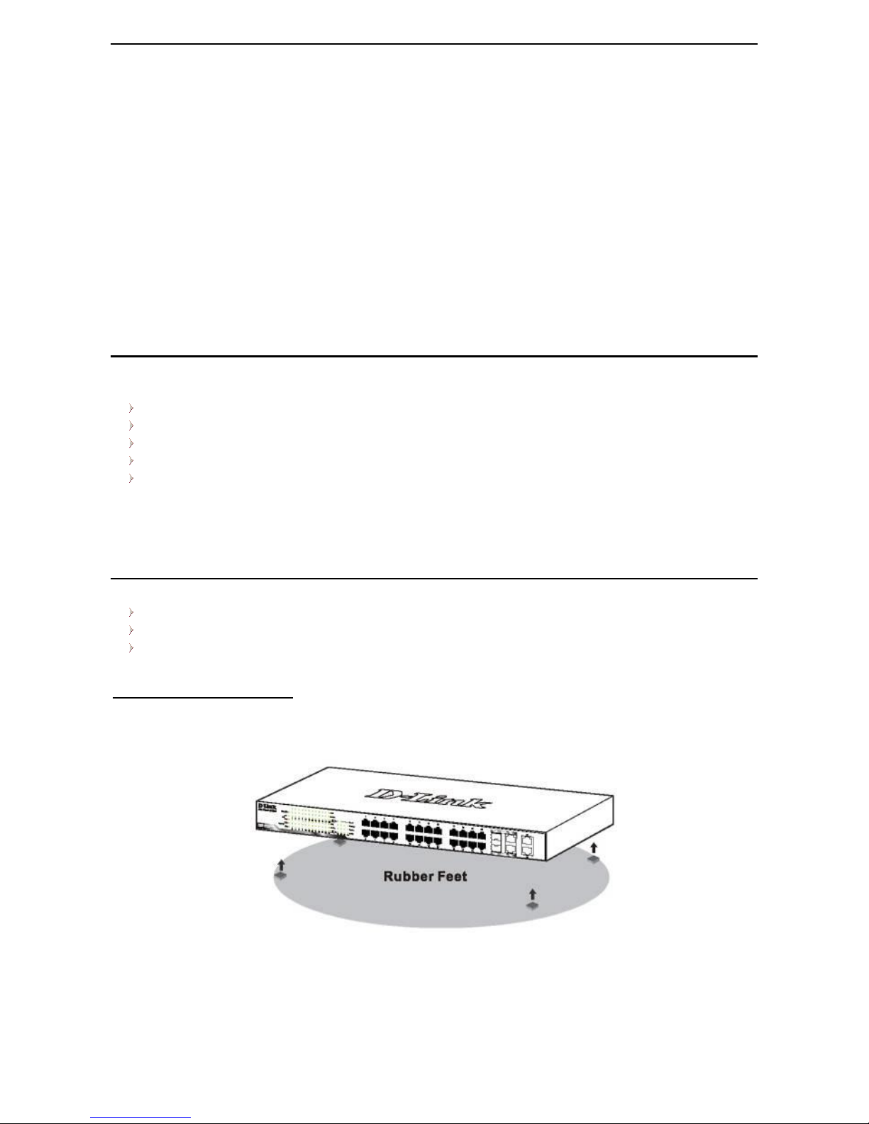
Desktop or Shelf Installation
When installing the switch on a desktop or shelf, the rubber feet included with the device must be attached
on the bottom at each corner of the device’s base. Allow enough ventilation space between the device and
the objects around it.
Figure 2.1 – Attach the adhesive rubber pads to the bottom
D-Link DMS-1100 Series User Manual
9
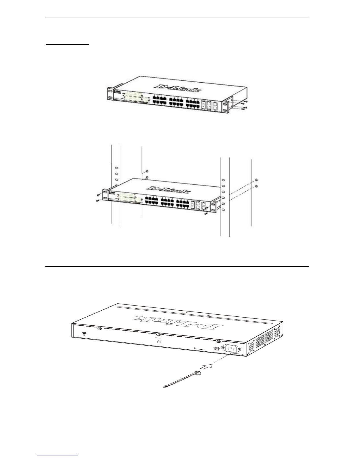
Rack Installation
The switch can be mounted in an EIA standard size 19-inch rack, which can be placed in a wiring closet with
other equipment. To install, attach the mounting brackets to the switch’s side panels (one on each side) and
secure them with the screws provided (with 8 M3*6.0 size screws).
Figure 2.2 – Attach the mounting brackets to the Switch
Then, use the screws provided with the equipment rack to mount the switch in the rack.
Figure 2.3 – Mount the Switch in the rack or chassis
Step 3 – Plugging in the AC Power Cord with Power Cord Clip
To prevent accidental removal of the AC power cord, it is recommended to install the power cord clip
together with the power cord.
A) With the rough side facing down, insert the Tie Wrap into the hole below the power socket.
Figure 2.1 – Insert Tie Wrap to the Switch
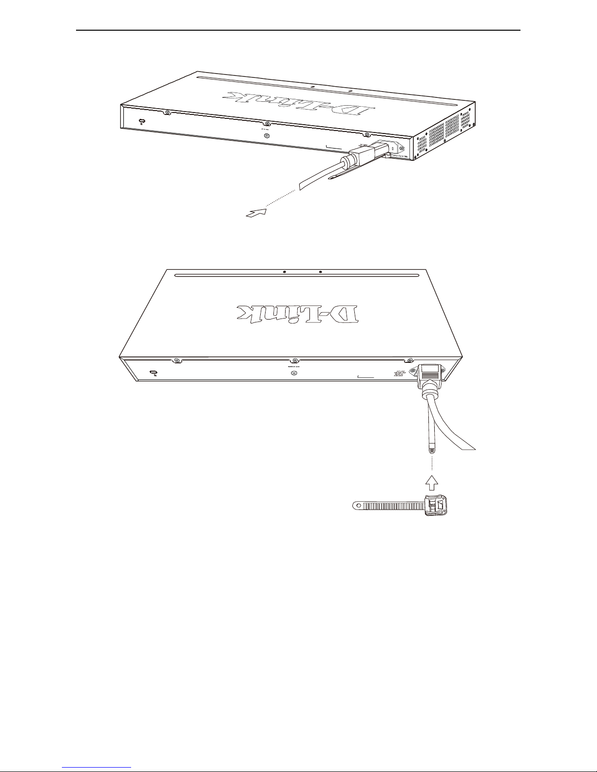
B) Plug the AC power cord into the power socket of the Switch.
D-Link DMS-1100 Series User Manual
10
Figure 2.2 – Connect the power cord to the Switch
C) Slide the Retainer through the Tie Wrap until the end of the cord.
Figure 2.3 – Slide the Retainer through the Tie Wrap
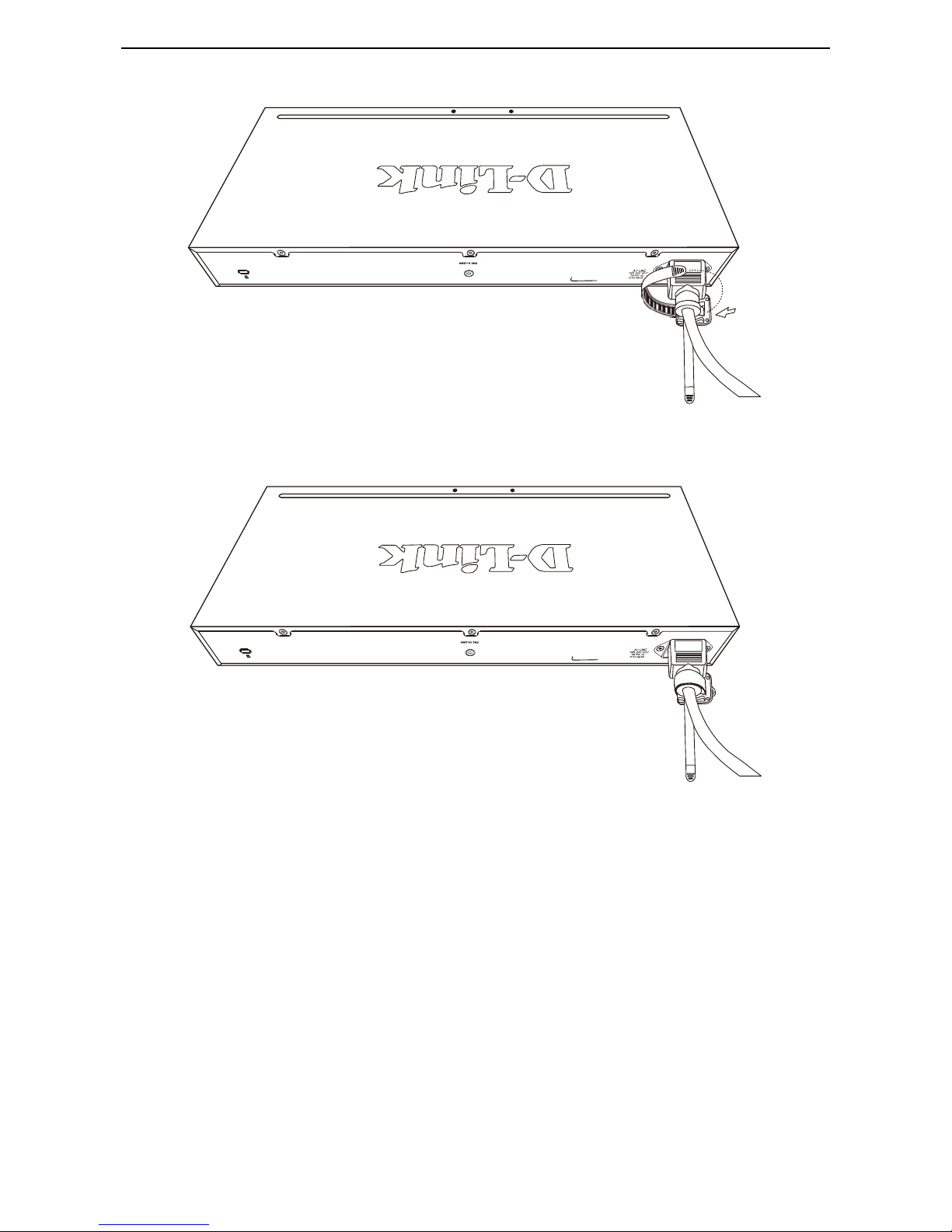
D) Circle the tie of the Retainer around the power cord and into the locker of the Retainer.
D-Link DMS-1100 Series User Manual
11
Figure 2.4 – Circle around the power cord
E) Fasten the tie of the Retainer until the power cord is secured.
Figure 2.5 – Secure the power cord
F) Users may now connect the AC power cord to an electrical outlet (preferably one that is grounded and
surge protected).
D-Link DMS-1100 Series User Manual
12
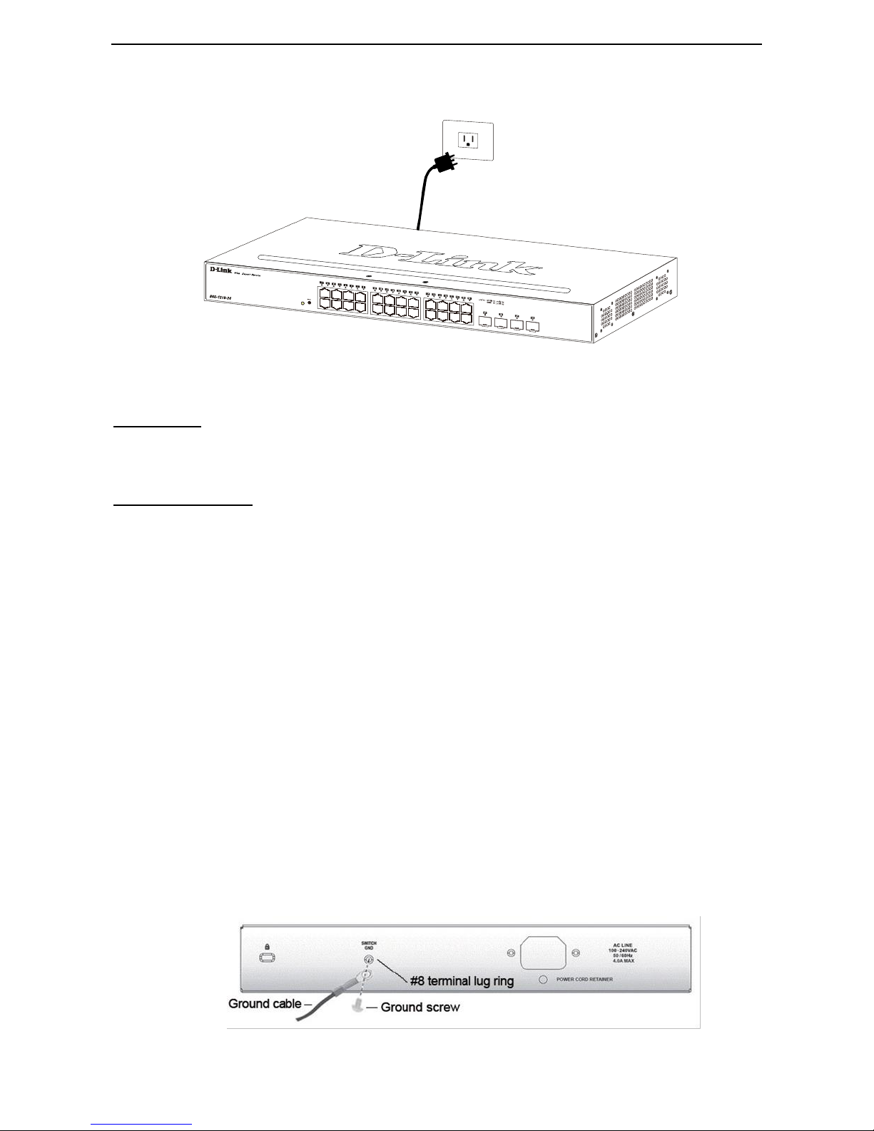
Figure 2.6 – Plugging the switch into an outlet
Power Failure
As a precaution, the switch should be unplugged in case of power failure. When power is resumed, plug the
switch back in.
Grounding the Switch
This section describes how to connect the DMS-1100 Series Switch to ground. You must complete this
procedure before powering your switch.
Required Tools and Equipment
Ground screws (included in the accessory kit): One M4 x 6 mm (metric) pan-head screw.
Ground cable (not included in the accessory kit): The grounding cable should be sized according to
local and national installation requirements. Depending on the power supply and system, a 12 to 6
AWG copper conductor is required for U.S installation. Commercially available 6 AWG wire is
recommended. The length of the cable depends on the proximity of the switch to proper grounding
facilities.
A screwdriver (not included in the accessory kit)
The following steps let you connect the switch to a protective ground:
Step 1: Verify if the system power is off.
Step 2: Use the ground cable to place the #8 terminal lug ring on top of the ground-screw opening, as
seen in the figure below.
Step 3: Insert the ground screw into the ground-screw opening.
Step 4: Using a screwdriver, tighten the ground screw to secure the ground cable to the switch.
Step 5: Attach the terminal lug ring at the other end of the grounding cable to an appropriate grounding
stud or bolt on rack where the switch is installed.
Step 6: Verify if the connections at the ground connector on the switch and the rack are securely
attached.
Figure 2.10 – Connect a Grounding Cable
D-Link DMS-1100 Series User Manual
13
3 Getting Started
This chapter introduces the management interface of D-Link DMS-1100 Series Switch.
Management Options
The D-Link DMS-1100 Series Switch can be managed through any port by using the Web-based
Management.
Each switch must be assigned its own IP Address, which is used for communication with the Web-Based
Management or a SNMP network manager. The PC should have an IP address in the same subnet as the
switch. Each switch can allow up to four users to access the Web-Based Management concurrently.
Please refer to the following installation instructions for the Web-based Management.
Using Web-based Management
After a successful physical installation, you can configure the Switch, monitor the network status, and display
statistics using a web browser.
Supported Web Browsers
The embedded Web-based Management currently supports the following web browsers:
Internet Explorer 7 or later version
Chrome
Firefox
Safari
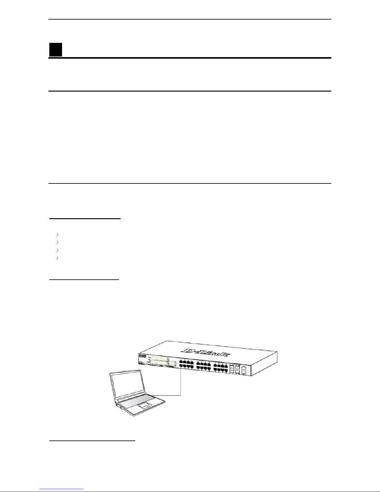
Connecting to the Switch
You will need the following equipment to begin the web configuration of your device:
1. A PC with a RJ-45 Ethernet connection
2. A standard Ethernet cable
Connect the Ethernet cable to any of the ports on the front panel of the switch and to the Ethernet port on the
PC.
Figure 3.1 – Connected Ethernet cable
Login Web-based Management
In order to login and configure the switch via Web-based GUI, the PC must have an IP address in the same
subnet as the switch. For example, if the switch has an IP address of 10.90.90.90, the PC should have an IP
D-Link DMS-1100 Series User Manual
14
address of 10.x.y.z (where x/y is a number between 0 ~ 254 and z is a number between 1 ~ 254), and a
subnet mask of 255.0.0.0. There are two ways to launch the Web-based Management.
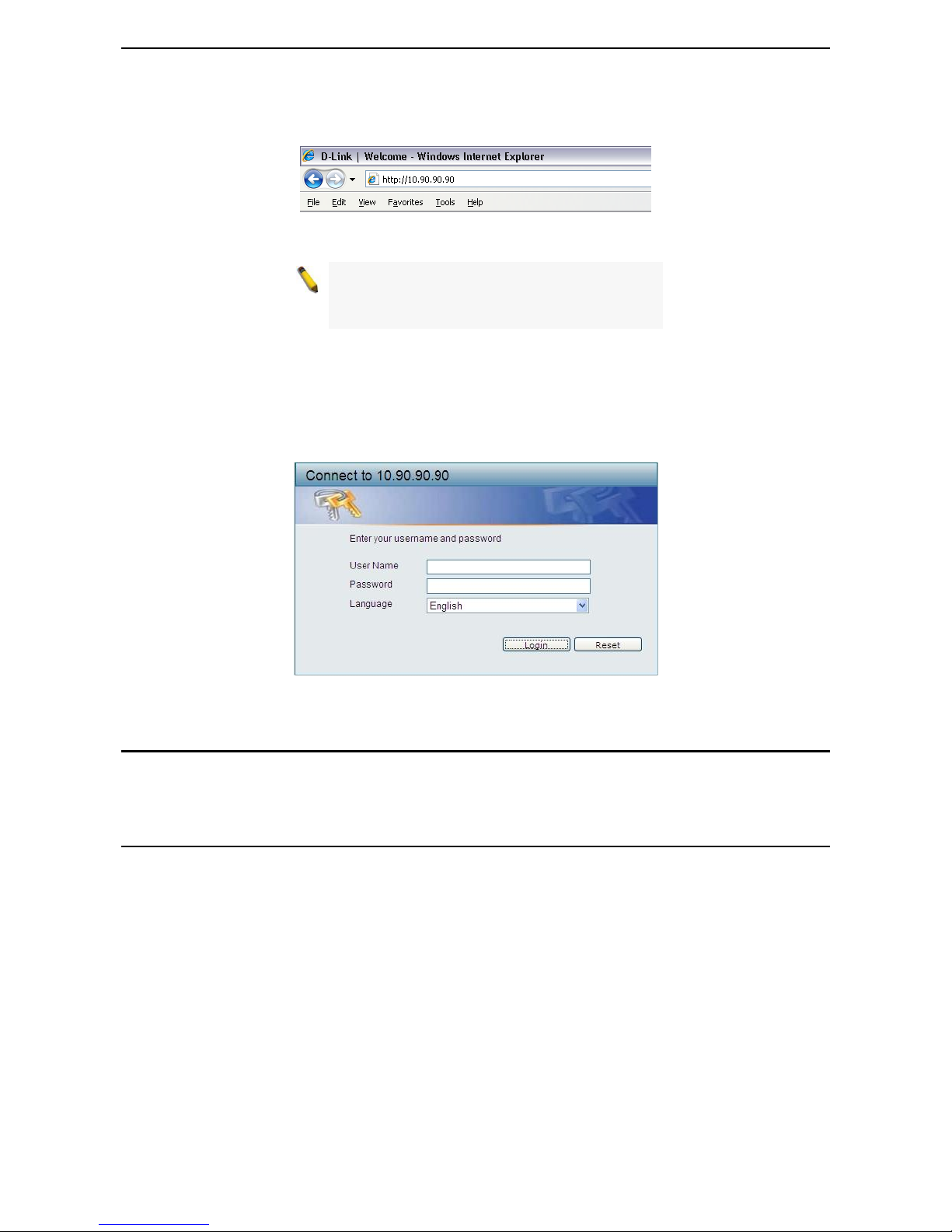
Figure 3.2 –Enter the IP address 10.90.90.90 in the web browser
NOTE: The switch's factory default IP address is
10.90.90.90 with a subnet mask of 255.0.0.0 and
a default gateway of 0.0.0.0.
When the following login dialog box appears, enter the password and choose the language of the Webbased Management interface then click OK.
The switch supports 10 languages including English, Traditional Chinese, Simplified Chinese, German,
Spanish, French, Italian, Portuguese, Japanese and Russian. By default, the language is English. Enter the
User name and Password with “admin” and press Login to enter the main configuration window.
Figure 3.3 – Login Dialog Box
Smart Wizard
After a successful login, the Smart Wizard will guide you through essential settings of the D-Link DMS-1100
Series Switch. Please refer to the Smart Wizard Configuration section for details.
Web-based Management
By clicking the Exit button in the Smart Wizard, you will enter the Web-based Management interface. Please
refer to Chapter 4 Configuration for detailed instructions.
D-Link DMS-1100 Series User Manual
15
4 Configuration
The features and functions of the D-Link DMS-1100 Series Switch can be configured for optimum use
through the Web-based Management Utility.
Smart Wizard Configuration
After a successful login, the Smart Wizard will guide you through essential settings of the D-Link DMS-1100
Series Switch. If you do not plan to change anything, click Exit to leave the Wizard and enter the Web
Interface. You can also skip it by clicking Ignore the wizard next time for the next time you logon to the
Web-based Management.
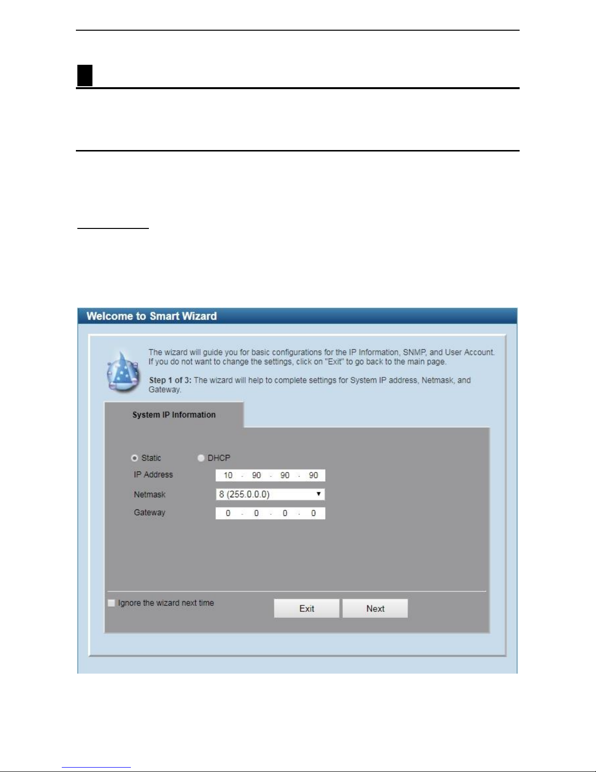
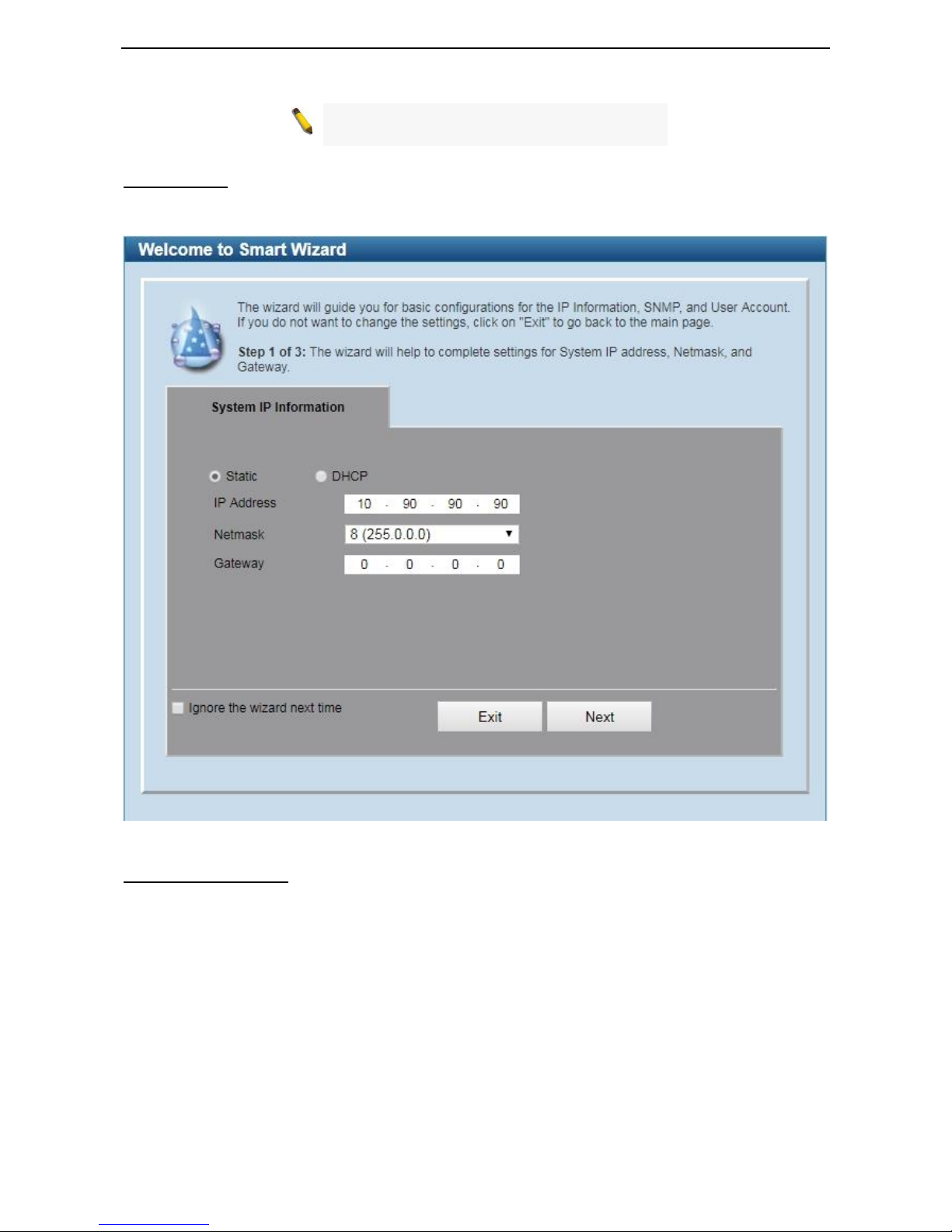
IPv4 Information
IPv4 Information will guide you to do basic configurations on 3 steps for the IP Information, access password,
and SNMP. Select Static, to manually enter a new IP Address, Netmask and Gateway address, or select
DHCP to automatically receive IP settings from a DHCP server. Click the Next button to enter the SNMP
settings page The IP address is allowed for IPv4 and IPv6 address. If you are not changing the settings, click
Exit button to go back to the main page. Or you can click on Ignore the wizard next time to skip wizard
setting when the switch boots up.
Figure 4.1 – IPv4 Information in Smart Wizard
D-Link DMS-1100 Series User Manual
16
NOTE: The IPv4 Information of Smart Wizard
does not support IPv6 address.
SNMP Settings
The SNMP Settings page allows user to quickly enable/disable the SNMP function. The default SNMP
Setting is Disabled. Click Enabled and then click Next, then it will enter the User Accounts Settings page.
Figure 4.2 – SNMP Settings in Smart Wizard
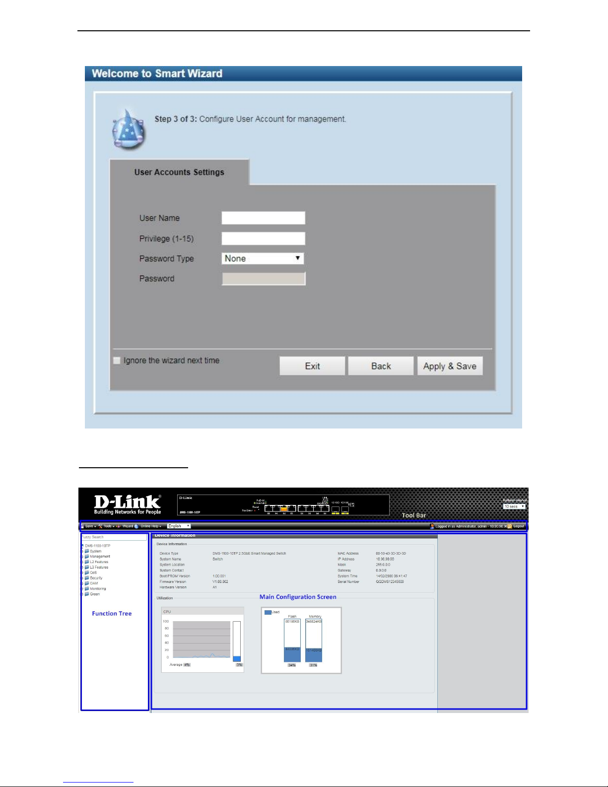
User Accounts Settings
The User Accounts Settings page allows user to quickly specify the user account function. Enter the User
Name, Privilege, Password Type and Password. Click Apply & Save to save the configuration.
D-Link DMS-1100 Series User Manual
17
Figure 4.3 – User Accounts Setting in Smart Wizard
Web-based Management
After clicking the Exit button in the Smart Wizard you will see the screen below:
Figure 4.4 – Web-based Management
D-Link DMS-1100 Series User Manual
18
The above image is the Web-based Management screen. The three main areas are the Tool Bar on top, the
Function Tree, and the Main Configuration Screen.
The Tool Bar provides a quick and convenient way for essential utility functions like firmware and
configuration management.
By choosing different functions in the Function Tree, you can change all the settings in the Main
Configuration Screen. The main configuration screen will show the current status of your Switch by clicking
the model name on top of the function tree.
At the upper right corner of the screen the username and current IP address will be displayed.
Under the username is the Logout button. Click this to end this session.
NOTE: If you close the web browser without
clicking the Logout button first, then it will be seen
as an abnormal exit and the login session will still
be occupied.
Click the D-Link logo at the upper-left corner of the screen to be redirected to the local D-Link website.
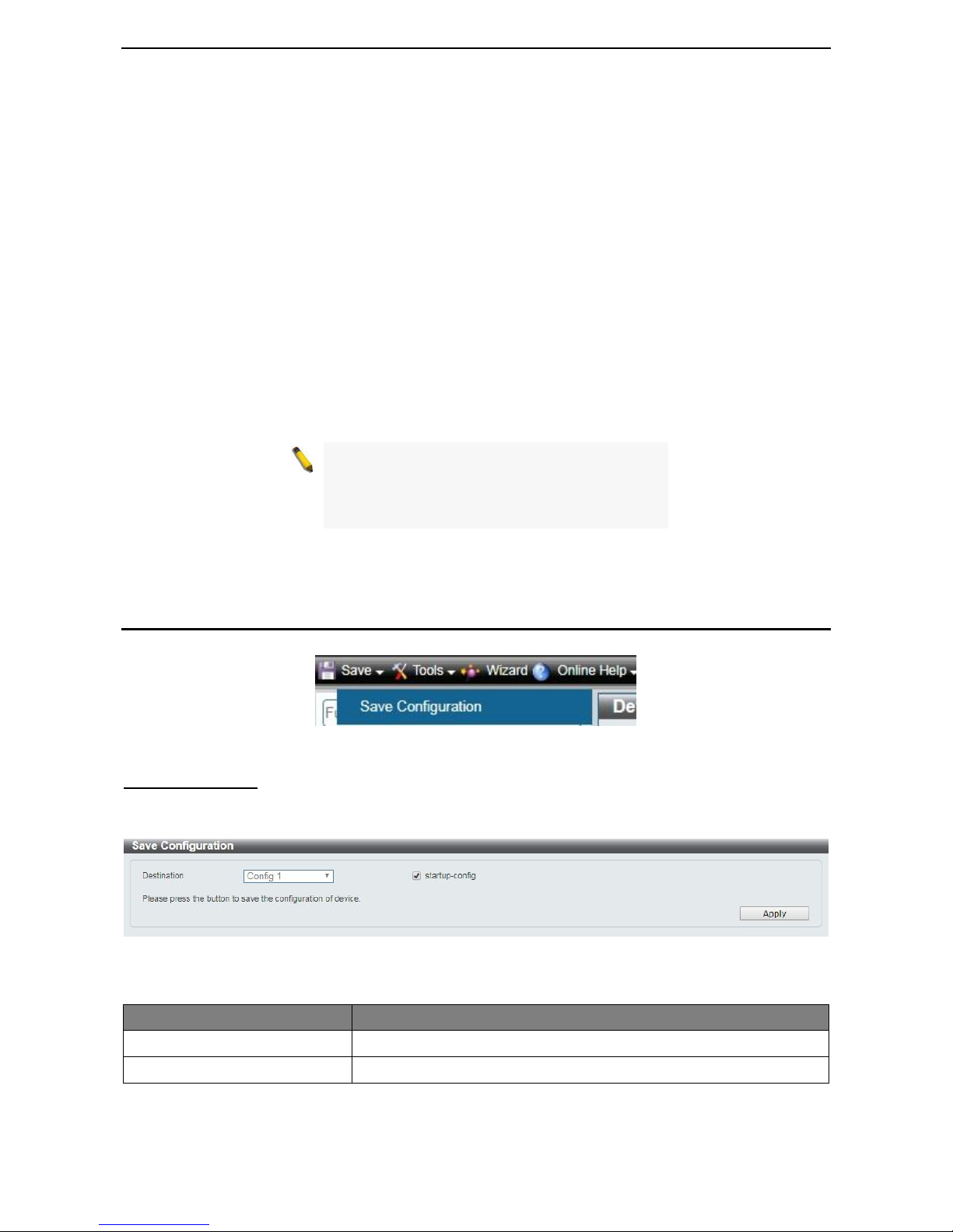
Tool Bar > Save Menu
The Save Menu provides Save Configuration and Save Log functions.
Figure 4.5 – Save Menu
Save Configuration
The Save Configuration page allows user to save the configuration changes to the S witch’s non-volatile
RAM.
Figure 4.6 – Save Configuration
The fields that can be configured for Save Configuration are described below:
Item
Description
Destination
Select the destination to save the configuration to.
Startup-config
Check the box to enable the startup configuration function.
Table 4.1
Click Apply to make the configurations take effect.
D-Link DMS-1100 Series User Manual
19
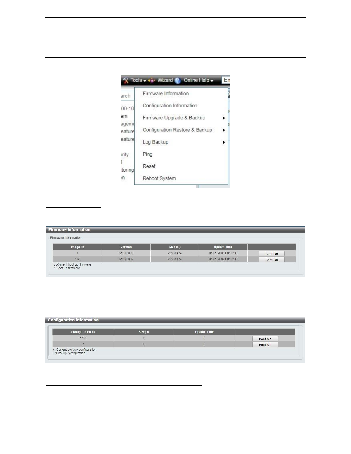
Tool Bar > Tool Menu
The Tool Menu offers global functions controls such as Reset, Reboot Device, Configuration Backup and
Restore, Firmware Backup and Upgrade.
Figure 4.7 – Tool Menu
Firmware Information
The Firmware Information page displays the firmware image information, including the image that has been
booted and the image that is selected for the next reboot.
Figure 4.8 – Tool Menu > Firmware Information
Configuration Information
The Configuration Information page displays information for the Switch configuration. This includes the
configuration that has been loaded and the configuration that is selected for the next reboot.
Figure 4.9 – Tool Menu > Configuration Information
Firmware Upgrade & Backup > Firmware Upgrade from HTTP
The Firmware upgrade from HTTP page allows user to upgrade the firmware of Switch from a firmware file.
D-Link DMS-1100 Series User Manual
20
Figure 4.10 – Tool Menu > Firmware Upgrade & Backup > Firmware Upgrade from HTTP
The fields that can be configured for Firmware Upgrade are described below:
Item
Description
Source URL
Click Choose File button to select the source URL to upgrade the
configuration from.
Destination URL
Displays the destination URL to upgrade to.
Table 4.2
Click Upgrade button to upload firmware to the Switch via HTTP.
Note: The new firmware will be set as another image in dual image system. User have to go
"system>firmware information" to select new image as boot up firmware and reboot the system.
Then new firmware will be activated.
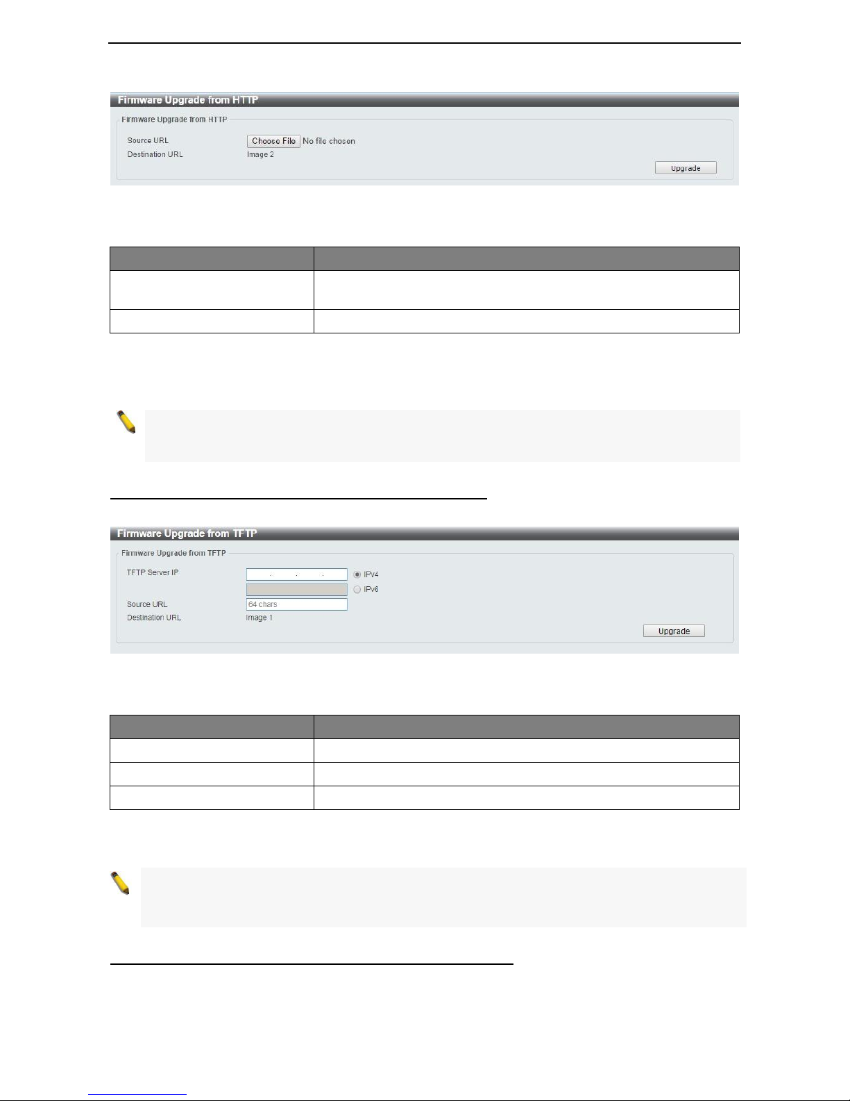
Firmware Upgrade & Backup > Firmware Upgrade from TFTP
This Firmware Upgrade from TFTP page allows user to upgrade firmware using TFTP.
Figure 4.11 – Tool Menu > Firmware Upgrade & Backup > Firmware Upgrade from TFTP
The fields that can be configured for Firmware Upgrade from TFTP are described below:
Item
Description
TFTP Server IP
Select IPv4 or IPv6 and enter the address to be configured.
Source URL
Enter the source URL address.
Destination URL
Displays the destination URL address.
Table 4.3
Click the Upgrade button to upgrade the firmware from specified TFTP address.
Note: The new firmware will be set as another image in dual image system. User have to go
"system>firmware information" to select new image as boot up firmware and reboot the system. Then
new firmware will be activated.
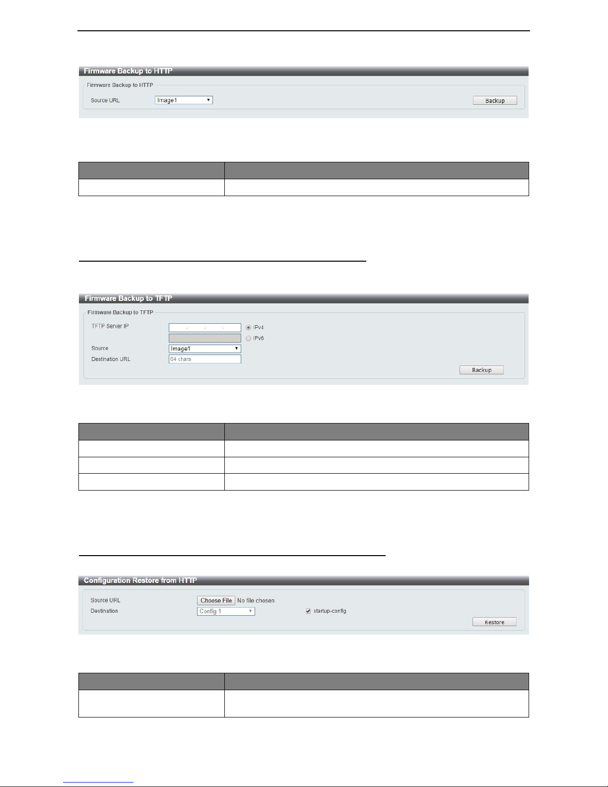
Firmware Backup to HTTP & Backup > Firmware Backup to HTTP
The Firmware Backup to HTTP page allows user to save a backup of the firmware, select the source URL
and then click Backup.
D-Link DMS-1100 Series User Manual
21
Figure 4.12 – Tool Menu > Firmware Upgrade & Backup > Firmware Backup to HTTP
The fields that can be configured for Firmware Backup to HTTP are described below:
Item
Description
Source URL
Select the source URL to be backup to.
Table 4.4
Click Backup button to backup the specified firmware.
Firmware Backup to HTTP & Backup > Firmware Backup to TFTP
The Firmware Backup to TFTP allows user to save a backup of the firmware using TFTP, enter the TFTP
server IP address, the source URL, and the destination URL. Click Backup.
Figure 4.13 – Tool Menu > Firmware Upgrade & Backup > Firmware Backup to TFTP
The fields that can be configured for Firmware Backup to TFTP are described below:
Item
Description
TFTP Server IP
Select IPv4 or IPv6 and enter the address to be configured.
Source
Enter the source URL address.
Destination URL
Displays the destination URL address.
Table 4.5
Click the Upgrade button to upgrade the firmware to specified TFTP address.
Configuration Upgrade & Backup > Configuration Restore from HTTP
The Configuration Restore from HTTP page allows user to restore the Switch from a saved configuration file.
Figure 4.14 – Tool Menu > Configuration Upgrade & Backup > Configuration Restore from HTTP
The fields that can be configured for Configuration Restore are described below:
Item
Description
Source URL
Click Choose File button to select the source URL to restore the
configuration from.
D-Link DMS-1100 Series User Manual
22
Destination URL
Displays the destination URL to upgrade to.
Startup-config
Check the box to enable the startup configuration function.
Table 4.6
Click Restore button to upload configuration to the Switch via HTTP.
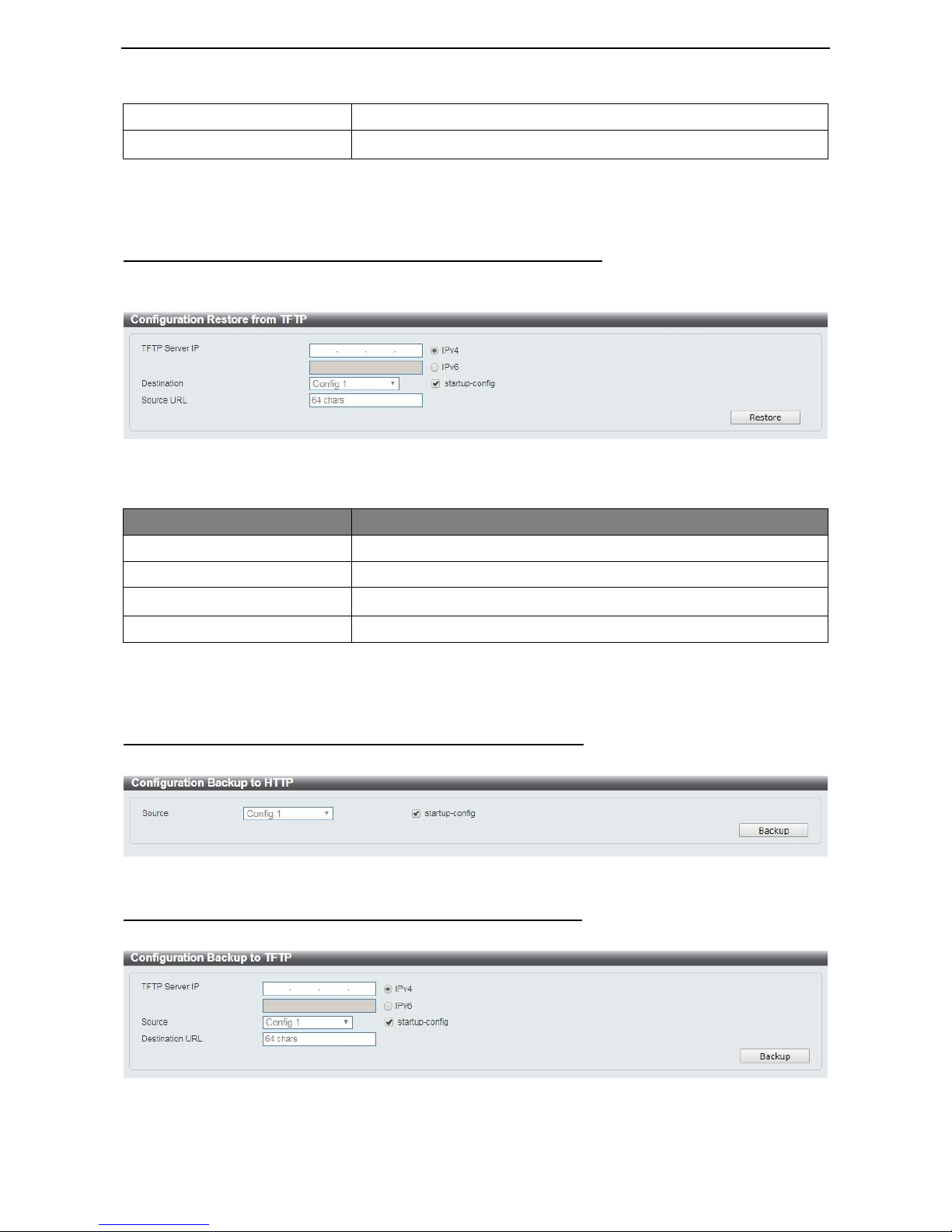
Configuration Upgrade & Backup > Configuration Restore from TFTP
The Configuration Restore from TFTP page allows user to load the Switch’s configuration from a saved
configuration file using TFTP.
Figure 4.15 – Tool Menu > Configuration Upgrade & Backup > Configuration Restore from TFTP
The fields that can be configured for Configuration Restore from TFTP are described below:
Item
Description
TFTP Server IP
Select IPv4 or IPv6 and enter the address to be configured.
Destination URL
Displays the destination URL address.
Startup-config
Check the box to enable the startup configuration function.
Source URL
Enter the source URL address.
Table 4.7
Click the Restore button to upgrade the configuration from specified TFTP address.
Configuration Upgrade & Backup > Configuration Backup to HTTP
The Configuration Backup to HTTP page allows user to save the current configuration to a file.
Figure 4.16 – Tool Menu > Configuration Upgrade & Backup > Configuration Backup to HTTP
Configuration Upgrade & Backup > Configuration Backup to TFTP
The Configuration Backup to TFTP page allows user to save the current configuration to a file using TFTP.
Figure 4.17 – Tool Menu > Configuration Upgrade & Backup > Configuration Backup to TFTP

D-Link DMS-1100 Series User Manual
23
The fields that can be configured for Configuration Backup from TFTP are described below:
Item
Description
TFTP Server IP
Select IPv4 or IPv6 and enter the address to be configured.
Source
Enter the source URL address.
Startup-config
Check the box to enable the startup configuration function.
Destination URL
Displays the destination URL address.
Table 4.8
Click the Backup button to save the configuration from specified TFTP address.
Log Backup > Log Backup to HTTP
The Log Backup to HTTP page allows user to save the log to a file.
Figure 4.18 – Tool Menu > Log Backup > Log Backup to HTTP
Log Backup > Log Backup to TFTP
The Log Backup to TFTP page allows user to save the log to a file using TFTP.
Figure 4.19 – Tool Menu > Log Backup > Log Backup to TFTP
The fields that can be configured for Log Backup are described below:
Item
Description
TFTP Server IP
Select IPv4 or IPv6 and enter the address to be configured.
Destination URL
Enter the destination URL for the backup.
Table 4.9
Click the Backup button to save the log to specified TFTP address.
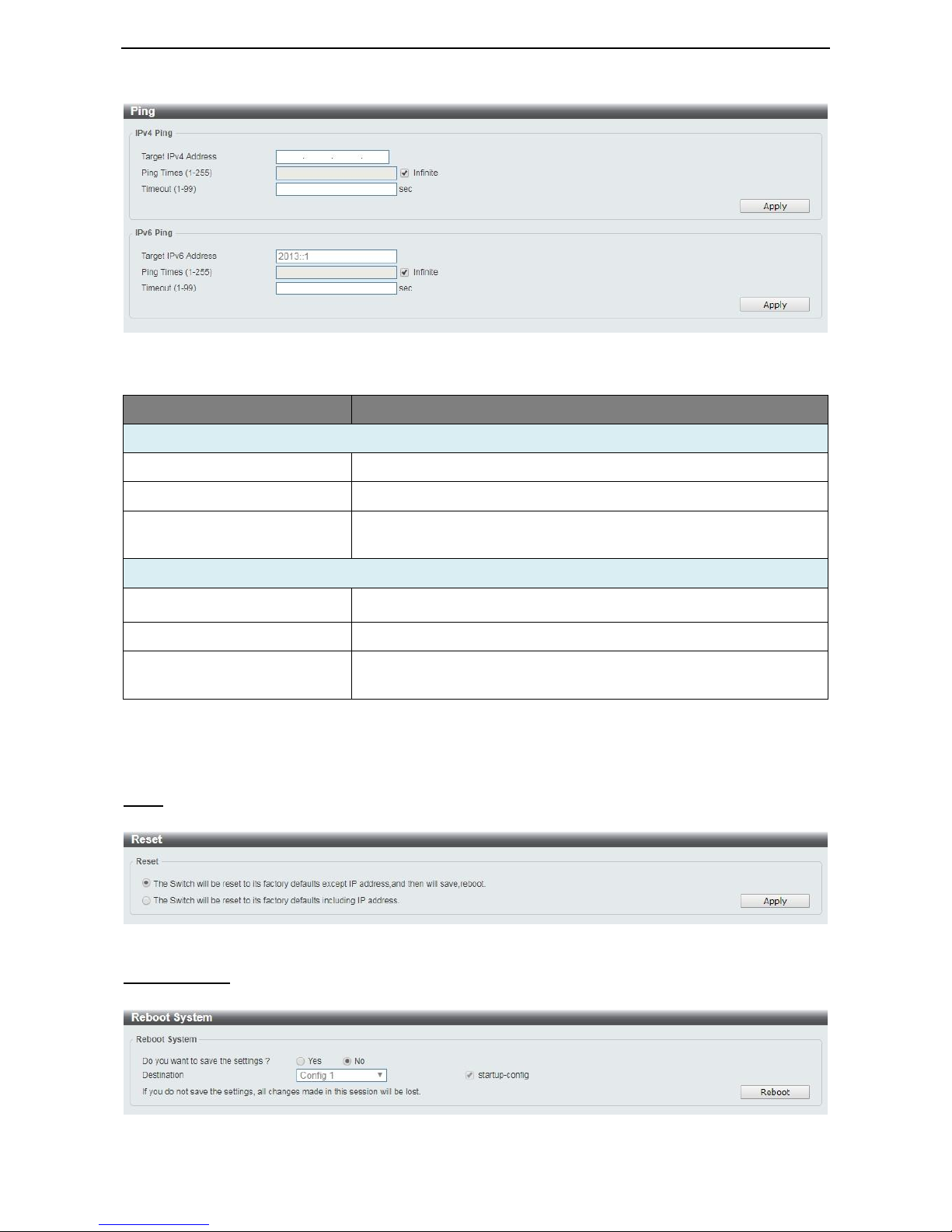
Ping
The Ping page allows user to ping a computer or device. The result will be displayed in the Result box.
D-Link DMS-1100 Series User Manual
24
Figure 4.20 – Ping
The fields that can be configured for Ping are described below:
Item
Description
IPv4 Ping
Target Ipv4 Address
Enter the IPv4 address to be pinged.
Ping Times (1-255)
Specify the ping time. The range is from 1 to 255.
Timeout (1-99)
Specify the timeout period while waiting for a response from the remote
device. The range is from 1 to 99 seconds.
IPv6 Ping
Target Ipv6 Address
Enter the IPv6 address to be pinged.
Ping Times (1-255)
Specify the ping time. The range is from 1 to 255.
Timeout (1-99)
Specify the timeout period while waiting for a response from the remote
device. The range is from 1 to 99 seconds.
Table 4.10
Click Apply to make the configurations take effect.
Reset
Select which reset option you want to perform and click Apply.
Figure 4.21 – Tool Menu > Reset
Reboot System
Select to save your current settings and then click Reboot to restart the Switch.
Figure 4.22 – Tool Menu > Reboot System
 Loading...