

Page 1

D-Link™ DGS-3100 Series
Gigabit Stackable Managed Switch
CLI Manual
V1.00
Page 2

DGS-3100 Series Gigabit Stackable Managed Switch CLI Manual
Information in this document is subject to change without notice.
© 2007 D-Link Computer Corporation. All rights reserved.
Reproduction in any manner whatsoever without the written permission of D-Link Computer Corporation is
strictly forbidden.
Trademarks used in this text: D-Link and the D-Link logo are trademarks of D-Link Computer Corporation;
Microsoft and Windows are registered trademarks of Microsoft Corporation.
Other trademarks and trade names may be used in this document to refer to either the entities claiming the
marks and names or their products. D-Link Computer Corporation disclaims any proprietary interest in
trademarks and trade names other than its own.
FCC Warning
This equipment has been tested and found to comply with the limits for a Class A digital device, pursuant to Part
15 of the FCC Rules. These limits are designed to provide reasonable protection against harmful interference
when the equipment is operated in a commercial environment. This equipment generates, uses, and can radiate
radio frequency energy and, if not installed and used in accordance with this user’s guide, may cause harmful
interference to radio communications. Operation of this equipment in a residential area is likely to cause harmful
interference in which case the user will be required to correct the interference at his own expense.
CE Mark Warning
This is a Class A product. In a domestic environment, this product may cause radio interference in which case
the user may be required to take adequate measures.
Warnung!
Dies ist ein Produkt der Klasse A. Im Wohnbereich kann dieses Produkt Funkstoerungen verursachen. In
diesem Fall kann vom Benutzer verlangt werden, angemessene Massnahmen zu ergreifen.
Precaución!
Este es un producto de Clase A. En un entorno doméstico, puede causar interferencias de radio, en cuyo case,
puede requerirse al usuario para que adopte las medidas adecuadas.
Attention!
Ceci est un produit de classe A. Dans un environnement domestique, ce produit pourrait causer des
interférences radio, auquel cas l`utilisateur devrait prendre les mesures adéquates.
Attenzione!
Il presente prodotto appartiene alla classe A. Se utilizzato in ambiente domestico il prodotto può causare
interferenze radio, nel cui caso è possibile che l`utente debba assumere provvedimenti adeguati.
VCCI Warning
March 2007
i
Page 3

DGS-3100 Series Gigabit Stackable Managed Switch CLI Manual
Table of Contents
INTRODUCTION ......................................................................................................................................................1
USING THE CONSOLE CLI.....................................................................................................................................4
COMMAND SYNTAX...............................................................................................................................................8
BASIC SWITCH COMMANDS...............................................................................................................................11
create account...................................................................................................................................................................... 12
config account..................................................................................................................................................................... 12
show account....................................................................................................................................................................... 12
show session........................................................................................................................................................................ 13
show switch......................................................................................................................................................................... 14
show serial_port .................................................................................................................................................................. 14
config serial_port ................................................................................................................................................................ 15
enable clipaging .................................................................................................................................................................. 15
disable clipaging ................................................................................................................................................................. 16
delete account...................................................................................................................................................................... 16
enable web .......................................................................................................................................................................... 17
disable web.......................................................................................................................................................................... 17
save ..................................................................................................................................................................................... 18
reboot .................................................................................................................................................................................. 18
reset..................................................................................................................................................................................... 18
login .................................................................................................................................................................................... 19
logout .................................................................................................................................................................................. 19
ping ..................................................................................................................................................................................... 19
show cpu utilization ............................................................................................................................................................ 20
show configuration.............................................................................................................................................................. 21
enable jumbo_frame............................................................................................................................................................ 21
disable jumbo_frame........................................................................................................................................................... 22
show jumbo_frame.............................................................................................................................................................. 22
locate................................................................................................................................................................................... 22
SWITCH PORT COMMANDS................................................................................................................................24
config ports ......................................................................................................................................................................... 24
show ports ........................................................................................................................................................................... 25
config ports description....................................................................................................................................................... 26
delete ports description ....................................................................................................................................................... 26
show ports description ........................................................................................................................................................ 26
NETWORK MANAGEMENT (SNMP) COMMANDS .............................................................................................28
create snmp user.................................................................................................................................................................. 29
delete snmp user.................................................................................................................................................................. 30
show snmp user................................................................................................................................................................... 30
create snmp view................................................................................................................................................................. 31
delete snmp view................................................................................................................................................................. 31
show snmp view.................................................................................................................................................................. 32
create snmp community ...................................................................................................................................................... 33
delete snmp community ...................................................................................................................................................... 33
show snmp community ....................................................................................................................................................... 34
config snmp engineID......................................................................................................................................................... 34
ii
Page 4

DGS-3100 Series Gigabit Stackable Managed Switch CLI Manual
show snmp engineID........................................................................................................................................................... 35
create snmp group ............................................................................................................................................................... 35
delete snmp group ............................................................................................................................................................... 37
show snmp groups............................................................................................................................................................... 37
create snmp host.................................................................................................................................................................. 39
delete snmp host.................................................................................................................................................................. 40
show snmp host................................................................................................................................................................... 40
create trusted_host............................................................................................................................................................... 41
show trusted_host................................................................................................................................................................ 41
delete trusted_host............................................................................................................................................................... 42
enable snmp traps................................................................................................................................................................ 42
disable snmp traps............................................................................................................................................................... 43
enable snmp authenticate trap ............................................................................................................................................. 43
disable snmp authenticate trap ............................................................................................................................................ 43
show snmp traps.................................................................................................................................................................. 44
config snmp system_contact ............................................................................................................................................... 44
config snmp system_location.............................................................................................................................................. 45
config snmp system_name.................................................................................................................................................. 45
DOWNLOAD/UPLOAD COMMANDS...................................................................................................................46
download............................................................................................................................................................................. 46
upload.................................................................................................................................................................................. 47
NETWORK MONITORING COMMANDS..............................................................................................................48
show packet ports................................................................................................................................................................ 48
show error ports .................................................................................................................................................................. 49
show utilization................................................................................................................................................................... 50
clear counters ...................................................................................................................................................................... 50
clear log............................................................................................................................................................................... 51
show log.............................................................................................................................................................................. 51
enable syslog....................................................................................................................................................................... 52
disable syslog...................................................................................................................................................................... 52
show syslog......................................................................................................................................................................... 53
create syslog host ................................................................................................................................................................ 53
config syslog host................................................................................................................................................................ 55
delete syslog host ................................................................................................................................................................ 57
show syslog host ................................................................................................................................................................. 58
SPANNING TREE COMMANDS............................................................................................................................59
config stp............................................................................................................................................................................. 59
config stp ports.................................................................................................................................................................... 60
config stp version................................................................................................................................................................ 61
enable stp ............................................................................................................................................................................ 62
disable stp............................................................................................................................................................................ 62
show stp .............................................................................................................................................................................. 63
show stp ports ..................................................................................................................................................................... 64
show stp instance_id ........................................................................................................................................................... 64
show stp mst_config_id ...................................................................................................................................................... 65
config stp instance_id.......................................................................................................................................................... 66
config stp priority................................................................................................................................................................ 67
iii
Page 5

DGS-3100 Series Gigabit Stackable Managed Switch CLI Manual
config stp mst_config_id..................................................................................................................................................... 67
config stp mst_ports............................................................................................................................................................ 68
FORWARDING DATABASE COMMANDS...........................................................................................................70
create fdb............................................................................................................................................................................. 70
create multicast_fdb ............................................................................................................................................................ 71
config multicast_fdb ........................................................................................................................................................... 71
config fdb aging_time ......................................................................................................................................................... 72
delete fdb............................................................................................................................................................................. 72
clear fdb .............................................................................................................................................................................. 73
show multicast_fdb ............................................................................................................................................................. 73
show fdb.............................................................................................................................................................................. 74
BROADCAST STORM CONTROL COMMANDS.................................................................................................76
config traffic control ........................................................................................................................................................... 76
show traffic control ............................................................................................................................................................. 77
QOS COMMANDS.................................................................................................................................................78
config scheduling ................................................................................................................................................................ 78
show scheduling.................................................................................................................................................................. 79
config 802.1p user_priority................................................................................................................................................. 80
show 802.1p user_priority................................................................................................................................................... 80
config 802.1p default_priority ............................................................................................................................................ 81
show 802.1p default_priority .............................................................................................................................................. 82
config scheduling_mechanism............................................................................................................................................ 82
show scheduling_mechanism.............................................................................................................................................. 83
config rate_limit.................................................................................................................................................................. 84
show rate_limit.................................................................................................................................................................... 84
PORT MIRRORING COMMANDS.........................................................................................................................86
config mirror ....................................................................................................................................................................... 86
delete mirror........................................................................................................................................................................ 87
show mirror......................................................................................................................................................................... 87
VLAN COMMANDS ...............................................................................................................................................88
create vlan ........................................................................................................................................................................... 88
delete vlan ........................................................................................................................................................................... 89
config vlan .......................................................................................................................................................................... 89
config gvrp.......................................................................................................................................................................... 90
enable gvrp.......................................................................................................................................................................... 90
disable gvrp......................................................................................................................................................................... 91
show vlan ............................................................................................................................................................................ 91
show gvrp............................................................................................................................................................................ 92
LINK AGGREGATION COMMANDS ....................................................................................................................93
create link_aggregation ....................................................................................................................................................... 93
delete link_aggregation ....................................................................................................................................................... 94
config link_aggregation ...................................................................................................................................................... 94
show link_aggregation ........................................................................................................................................................ 95
BASIC IP COMMANDS..........................................................................................................................................96
config ipif system................................................................................................................................................................ 96
show ipif.............................................................................................................................................................................. 97
IGMP SNOOPING COMMANDS............................................................................................................................98
iv
Page 6

DGS-3100 Series Gigabit Stackable Managed Switch CLI Manual
config igmp_snooping......................................................................................................................................................... 98
config router_port ............................................................................................................................................................... 99
enable igmp_snooping ........................................................................................................................................................ 99
disable igmp_snooping ..................................................................................................................................................... 100
show igmp_snooping ........................................................................................................................................................ 100
show igmp_snooping group .............................................................................................................................................. 101
show igmp_snooping forwarding...................................................................................................................................... 101
show router_port ............................................................................................................................................................... 102
802.1X COMMANDS............................................................................................................................................103
enable 802.1x .................................................................................................................................................................... 103
disable 802.1x ................................................................................................................................................................... 104
show 802.1x auth_state ..................................................................................................................................................... 104
show 802.1x auth_configuration....................................................................................................................................... 105
config 802.1x auth_parameter ports.................................................................................................................................. 106
config 802.1x init .............................................................................................................................................................. 107
config 802.1x auth_protocol ............................................................................................................................................. 108
config 802.1x reauth ......................................................................................................................................................... 108
config radius add............................................................................................................................................................... 109
config radius delete ........................................................................................................................................................... 109
config radius...................................................................................................................................................................... 110
show radius ....................................................................................................................................................................... 110
config 802.1x auth_mode.................................................................................................................................................. 111
config guest_vlan .............................................................................................................................................................. 111
config guest_vlan ports ..................................................................................................................................................... 112
show guest_vlan................................................................................................................................................................ 112
PORT SECURITY COMMANDS..........................................................................................................................113
config port_security .......................................................................................................................................................... 113
show port_security ............................................................................................................................................................ 114
TIME AND SNTP COMMANDS...........................................................................................................................115
config sntp......................................................................................................................................................................... 115
show sntp .......................................................................................................................................................................... 116
enable sntp ........................................................................................................................................................................ 116
disable sntp........................................................................................................................................................................ 117
config time date................................................................................................................................................................. 117
config time_zone............................................................................................................................................................... 118
config dst........................................................................................................................................................................... 118
show time.......................................................................................................................................................................... 120
ROUTING TABLE COMMANDS .........................................................................................................................121
create iproute..................................................................................................................................................................... 121
delete iproute..................................................................................................................................................................... 121
show iproute...................................................................................................................................................................... 122
ARP COMMANDS................................................................................................................................................123
create arpentry................................................................................................................................................................... 123
config arpentry.................................................................................................................................................................. 123
delete arpentry................................................................................................................................................................... 124
show arpentry.................................................................................................................................................................... 125
config arp_aging time ....................................................................................................................................................... 125
v
Page 7

DGS-3100 Series Gigabit Stackable Managed Switch CLI Manual
clear arptable..................................................................................................................................................................... 126
COMMAND HISTORY LIST COMMANDS..........................................................................................................127
?......................................................................................................................................................................................... 127
show command_history .................................................................................................................................................... 128
dir ...................................................................................................................................................................................... 128
config command_history................................................................................................................................................... 129
SSH COMMANDS................................................................................................................................................130
enable ssh.......................................................................................................................................................................... 130
disable ssh ......................................................................................................................................................................... 131
config ssh authmode.......................................................................................................................................................... 131
show ssh authmode ........................................................................................................................................................... 131
config ssh server................................................................................................................................................................ 132
show ssh server ................................................................................................................................................................. 132
show ssh algorithm............................................................................................................................................................ 133
config ssh crypto ............................................................................................................................................................... 133
show ssh crypto................................................................................................................................................................. 134
delete ssh crypto................................................................................................................................................................ 134
SSL COMMANDS................................................................................................................................................136
enable ssl........................................................................................................................................................................... 136
disable ssl.......................................................................................................................................................................... 137
show ssl............................................................................................................................................................................. 137
show ssl cachetimeout....................................................................................................................................................... 138
crypto certificate (generate) .............................................................................................................................................. 138
crypto certificate (request) ................................................................................................................................................ 139
crypto certificate (import) ................................................................................................................................................. 140
config ssl certificate .......................................................................................................................................................... 140
show crypto certificate mycertificate ................................................................................................................................ 141
ACCESS AUTHENTICATION CONTROL COMMANDS....................................................................................142
create authen_login method_list_name............................................................................................................................. 143
config authen_login........................................................................................................................................................... 143
delete authen_login method_list_name............................................................................................................................. 144
show authen_login ............................................................................................................................................................ 145
create authen_enable method_list_name........................................................................................................................... 145
config authen_enable ........................................................................................................................................................ 146
delete authen_enable method_list_name........................................................................................................................... 147
show authen_enable .......................................................................................................................................................... 148
config authen application .................................................................................................................................................. 148
show authen application.................................................................................................................................................... 149
create authen server_host.................................................................................................................................................. 150
config authen server_host ................................................................................................................................................. 151
delete authen server_host.................................................................................................................................................. 152
show authen server_host ................................................................................................................................................... 152
local_enable admin ........................................................................................................................................................... 153
config admin local_enable ................................................................................................................................................ 153
LACP COMMANDS .............................................................................................................................................155
config lacp port_priority ................................................................................................................................................... 155
show lacp .......................................................................................................................................................................... 155
vi
Page 8

DGS-3100 Series Gigabit Stackable Managed Switch CLI Manual
STACKING COMMANDS ....................................................................................................................................157
config box_id .................................................................................................................................................................... 157
show stack_information .................................................................................................................................................... 157
POE COMMANDS................................................................................................................................................159
config poe.......................................................................................................................................................................... 159
config poe ports................................................................................................................................................................. 160
show poe ........................................................................................................................................................................... 160
ACCESS CONTROL LIST COMMANDS ............................................................................................................162
create access_profile (Ethernet) ........................................................................................................................................ 162
create access_profile (IP) .................................................................................................................................................. 163
config access_profile (Ethernet) ....................................................................................................................................... 164
config access_profile (IP) ................................................................................................................................................. 166
config access_profile......................................................................................................................................................... 168
delete access_profile ......................................................................................................................................................... 168
show access_profile .......................................................................................................................................................... 169
TRAFFIC SEGMENTATION COMMANDS..........................................................................................................171
config traffic_segmentation .............................................................................................................................................. 171
show traffic_segmentation ................................................................................................................................................ 171
DEVICE SPECIFICATIONS.................................................................................................................................173
vii
Page 9
1
INTRODUCTION
The DGS-3100 is a member of the D-Link DGS-3100 switch family. The DGS 3100 product range consists of 24
/ 48 -port 10/100/1000Base-T PoE / NonPoE L2 Stackable Management Switches with 4 Combo SFPs.
The Switch can be managed through the Switch’s serial port, Telnet, or the Web-based management agent. The
Command Line Interface (CLI) can be used to configure and manage the Switch via the serial port or Telnet
interfaces.
This manual provides a reference for all of the commands contained in the CLI. Configuration and management
of the Switch via the Web-based management agent is discussed in the Manual. For detailed information on
installing hardware please refer also to the Manual.
Accessing the Switch via the Serial Port
The Switch’s serial port’s default settings are as follows:
• 9600 bps
• No parity
• 8 data bits
• 1 stop bit
A computer running a terminal emulation program capable of emulating a VT-100 terminal and a serial port
configured as above is then connected to the Switch’s serial port via an RS-232 DB-9 cable.
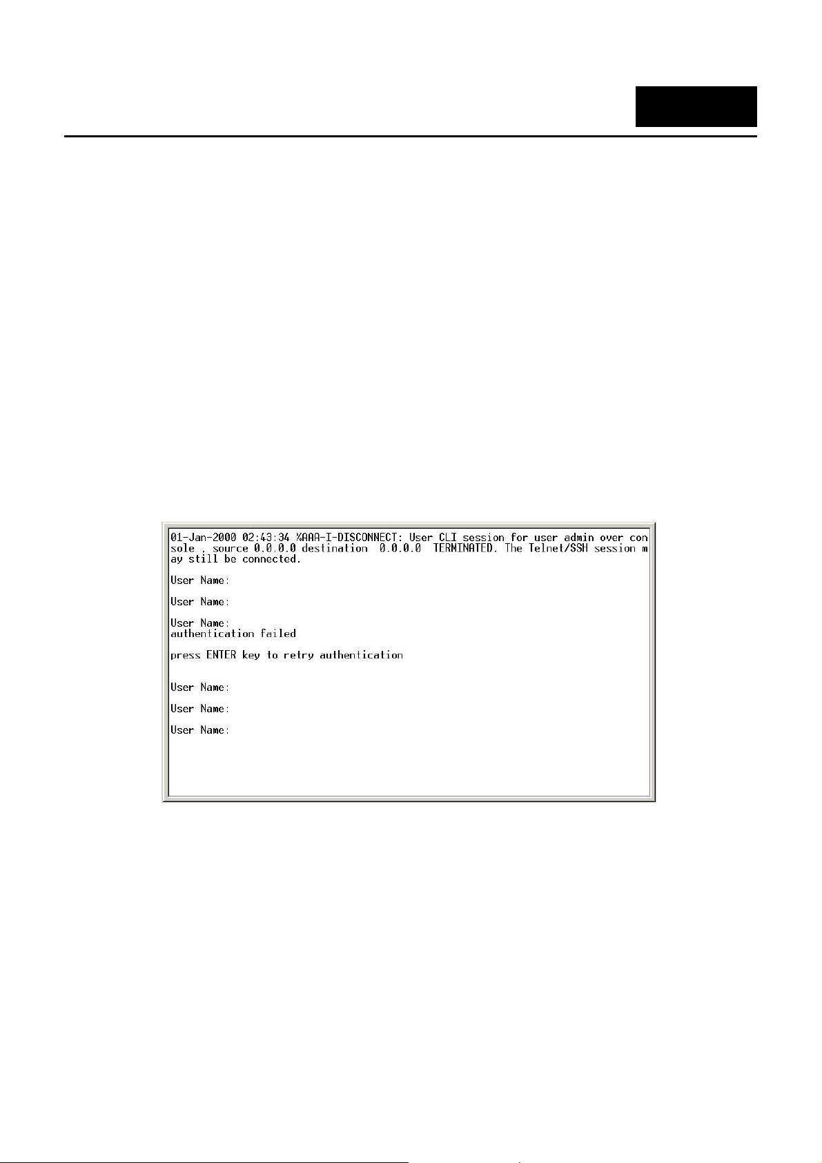
With the serial port properly connected to a management computer, the following screen should be visible. If this
screen does not appear, try pressing Ctrl+r to refresh the console screen.
[
Figure 1–1. Initial CLI screen
The initial username is admin (lower case). Press the Enter key twice to display the CLI input cursor. This is the
command line where all commands are input.
Setting the Switch’s IP Address
Each Switch must be assigned its own IP Address, which is used for communication with an SNMP network
manager or other TCP/IP application (for example BOOTP, TFTP). The Switch’s default IP address is
10.90.90.90. You can change the default Switch IP address to meet the specification of your networking address
scheme.
The Switch is also assigned a unique MAC address by the factory. This MAC address cannot be changed, and
can be found on the initial boot console screen – shown below.
1
Page 10
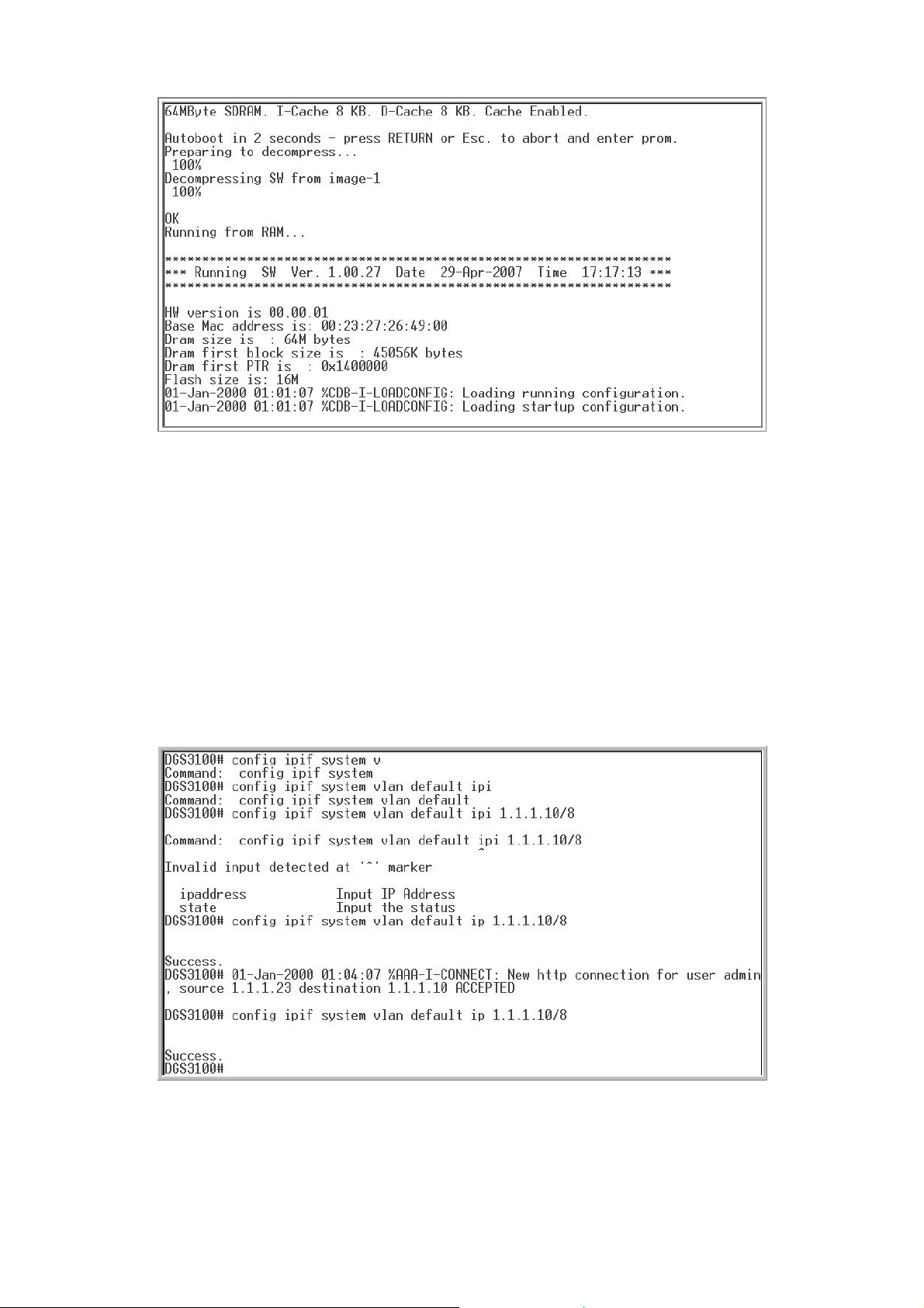
DGS-3100 Gigabit Ethernet Switch Manual
Figure 1–2. Boot Screen
The Switch’s MAC address can also be found in the Web management program on the Device Information
window on the Configuration menu.
The IP address for the Switch must be set before it can be managed with the Web-based manager. The Switch
IP address can be automatically set using BOOTP or DHCP protocols, in which case the actual address
assigned to the Switch must be known.
The IP address may be set using the Command Line Interface (CLI) over the console serial port as follows:
1. Starting at the command line prompt, enter the commands config ipif System vlan default ipaddress
xxx.xxx.xxx.xxx/yyy.yyy.yyy.yyy. Where the x’s represent the IP address to be assigned to the IP interface named
System and the y’s represent the corresponding subnet mask.
2. Alternatively, you can enter config ipif System ipaddress xxx.xxx.xxx.xxx/z. Where the x’s represent the IP
address to be assigned to the IP interface named System and the z represents the corresponding number of subnets
in CIDR notation.
The IP interface named System on the and subnet mask which can then
be used to connect a management s d management agent.
Switch can be assigned an IP address
tation to the Switch’s Telnet or Web-base
Figure 1–3. Assigning an IP Address
In the above example, the Switch was assigned an IP address of 10.53.13.26 with a subnet mask of 255.0.0.0.
The system message Success indicates that the command was executed successfully. The Switch can now be
2 3
Page 11

configured and managed via Telnet, SNMP MIB browser and the CLI or via the Web-based manage agent
using the above IP address to connect to the Switch.
NOTE: The DGS-3100 series of switches have the pability to be config d for an IP addre
of 0.0.0.0, or, in essence, have no IP address. Th
functions of the Switch. When the IP address is s
only be managed through the console port or SIM. Other management applications such as
Telnet, Web-based and SNMP cannot be used to manage the Switch when its IP address is
0.0.0.0.
ca ure ss
is function maybe used to disable Layer 3
et to 0.0.0.0 (invalid IP address), the Switch can
ment
Page 12
DGS-3100 Gigabit Ethernet Switch Manual
2
USING THE CONSOLE CLI
The Switch supports a console management interface that allows the user to connect to the Switch’s
management agent via a serial port and a terminal or a computer running a terminal emulation program. The
console can also be used over the network using the TCP/IP Telnet protocol. The console program can be used
to configure the Switch to use an SNMP-based network management software over the network.
This chapter describes how to use the console interface to access the Switch, change its settings, and monitor
its operation.
NOTE: Switch configuration settings are saved to non-volatile RAM using the save command.
The current configuration will then be retained in the Switch’s NV-RAM, and reloaded when the
Switch is rebooted. If the Switch is rebooted without using the save command, the last
configuration saved to NV-RAM will be loaded.
Connecting to the Switch
The console interface is used by connecting the Switch to a VT100-compatible terminal or a computer running
an ordinary terminal emulator program (for example, the HyperTerminal program included with the Windows
operating system) using an RS-232C serial cable.
• VT-100 compatible
• 9600 bps
• 8 data bits
• No parity
• One stop bit
• No flow control
Users may also access the same functions over a Telnet interface. Once you have set an IP address for your
Switch, you can use a Telnet program (in VT-10
All of the screens are identical, whether accessed from the console port or from a Telnet interface.
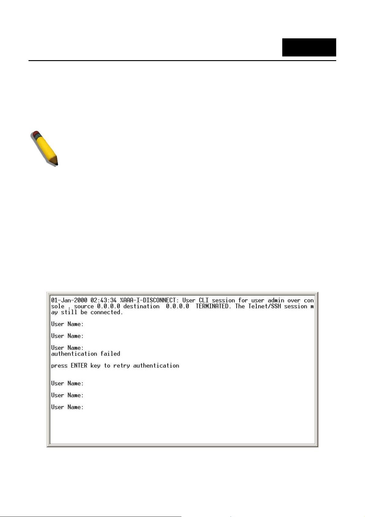
After the Switch reboots and you have logged in, the console looks like this:
Your terminal parameters will need to be set to:
0 compatible terminal mode) to access and control the Switch.
Figure 2–1. Initial Console Screen after Logging In
4
Page 13
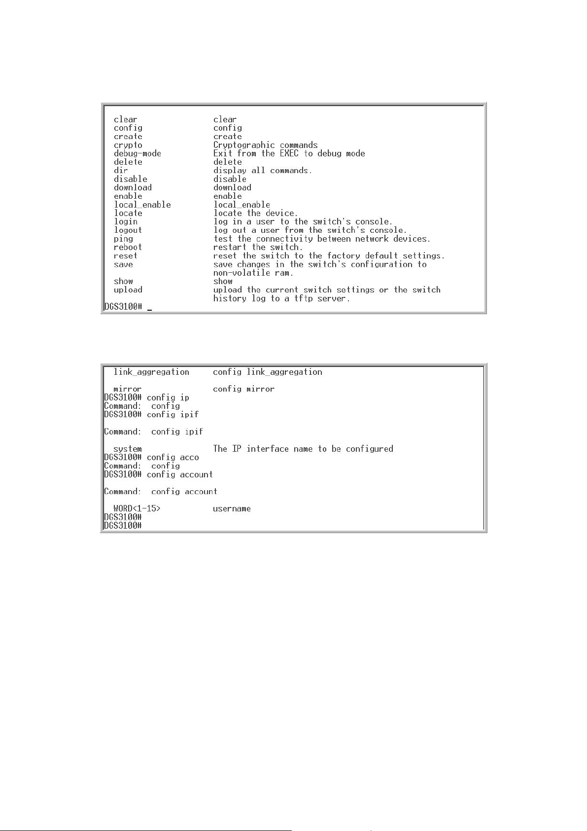
Commands are entered at the command prompt, DGS3100#.
There are a number of helpful features ommand will display a list of all of the included in the CLI. Entering the ? c
top-level commands.
Figure 2–2. The ? Command
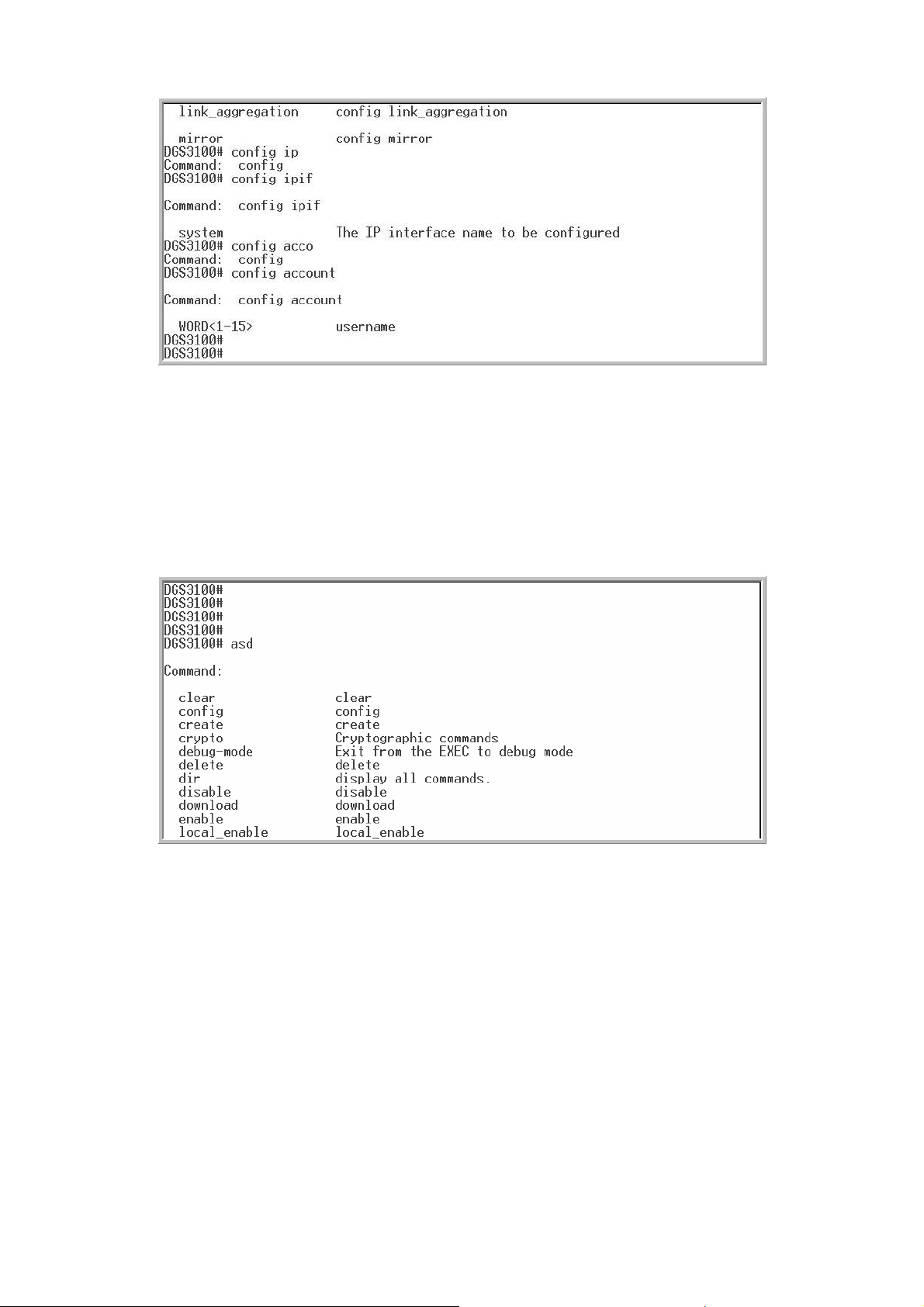
When entering a comma rompt: command: config nd without its required parameters, the CLI displays the p
account message and the options listed below.
Figure 2–3. Example Command Parameter Help
In this case, the command config account was entered with the parameter <username>. The CLI will then
prompt to enter the <username> with the message, command: config account. Every command in the CLI has
this feature, and complex commands have several layers of parameter prompting.
In addition, after typing any given command plus one space, users can see all of the next possible subcommands, in sequential order, by pressing the ? key.
To re-enter the previous command at the command prompt, press the up arrow cursor key. The previous
command will appear at the command prompt.
5
Page 14
DGS-3100 Gigabit Ethernet Switch Manual
Figure
2–4. Using the Up Arrow to Re-enter a Command
In the above rameter <username>,
the CLI returned the command: l key was pressed to re-enter
the previou config a be entered
and the con ommand
All command function in this way. In additi the help prompts are the same as
presented in this manual angle lue or character string. The < > can also
indicate a W mber fo character allowed.
a command is entered that is unrecognized by the CLI, the top-level commands will be displayed under the
If
Available c
example, the command config account was entered without the required pa
config account prompt. The up arrow cursor contro
s command (
fig account c
s in the CLI
ccount) at the command prompt. Now the appropriate username can
re-executed.
on, the syntax of
brackets < > indicate a numerical va
ord with nu
ommands: prompt.
Figure 2–5. Available Commands
The top-level ands consist of co commands require one or
more param narrow the t t? or config what? Where the
what? is the
For example, entering the show meters, the CLI will then display all of the
possible next para
comm
eters to
next parameter.
meters.
mmands such as show or config. Most of these
op-level command. This is equivalent to show wha
command with no additional para
6
Page 15

Figure 2–6. Next possible completions: Show Command
In the above meters for the show command are displayed. At the next
command w was used to re-enter the show command, followed by the
example, all of the possible next para
prompt in the example, the up arro
account parameter. The CLI then displays the user accounts configured on the Switch.
7
Page 16

DGS-3100 Gigabit Ethernet Switch Manual
3
COMMAND SYNTAX
The following symbols are used to describe how command entries are made and values and arguments are
specified in this manual. The online help contained in the CLI and available through the console interface uses
the same syntax.
NOTE: All commands are case-sensitive. Be sure to disable Caps Lock or any other unwanted
function that changes text case.
<angle brackets>
Purpose Encloses a variable or value that must be specified.
Syntax
Description In the above syntax example, users must supply a username in the
Example
Command
create account [admin | user] <username 15>
<username> space. Do not type the angle brackets.
create account admin newadmin1
[square brackets]
Purpose Encloses a required value or set of required arguments. One value
or argument can be specified.
Syntax
Description In the above syntax example, you must specify either an admin or a
Example
Command
create account [admin | user] <username 15>
user level account to be created. Do not type the square brackets.
create account user newuser1
| vertical bar
Purpose Separates two or more mutually exclusive items in a list, one of
which must be entered.
Syntax
Description In the above syntax example, users must specify either admin, or
Example
Command
All commands are case-sensitive. Be sure to disable Caps Lock or any other unwanted function that changes
text case.
create account [admin | user] <username 15>
user. Do not type the vertical bar.
create account user newuser1
8
Page 17

{braces}
Purpose Encloses an optional value or set of optional arguments.
Syntax reset {[config | system]}
Description In the above syntax example, users have the option to specify config
or system. It is not ne
however the effect of the system
value is specified. Therefore, with this example there are three
possible outcomes of performing a
chapter, Basic Com
command.
Example reset config
command
cessary to specify either optional value,
reset is dependent on which, if any,
system reset. See the following
mands for more details about the reset
Line Editing Key Usage
Delete Deletes the character under the cursor and then shifts the
remaining characters in the line to the left.
Backspace Deletes the character to the left of the cursor and then shifts the
remaining characters in the line to the left.
Insert or Ctrl+R Toggle on and off. When toggled on, inserts text and shifts previous
text to the right.
Left Arrow Moves the cursor to the left.
Right Arrow Moves the cursor to the right.
Up Arrow Repeats the previously entered command. Each time the up arrow
is pressed, the command previous to that displayed appears. This
way it is possible to review
session. Us
through the command history list.
Down Arrow The down arrow will display the next command in the command
history entered in the current session. This displays each command
sequentially as it was entered. Use the up arrow to review previous
commands.
Tab Shifts the cursor to the next field to the left.
e the down arrow to progress sequentially forward
the command history for the current
Multiple Pag ntrol Keys e Display Co
Space Displays the next page.
CTRL+c Stops the display of remaining pages when multiple pages are to be
displayed.
ESC Stops the display of remaining pages when multiple pages are to be
displayed.
n Displays the next page.
p Displays the previous page.
9
Page 18

DGS-3100 Gigabit Ethernet Switch Manual
q s the display of remaining pages when multiple pages are to be
Stop
disp
layed.
r Re y displayed. freshes the pages currentl
a Displays the remaining pages without pausing between pages.
Enter Displays the next line or table entry.
10
Page 19

4
SWITCH COMMANDS BASIC
The Basic S nds in mand Line Interface (CLI) are listed (along with the appropriate
parameters) in the following table.
witch comma the Com
Command Parameter
create account [admin | user] <username 15>
config account <username 15>
show account
show session
show switch
show serial_port
config serial_port
enable clipaging
disable clipaging
delete acc <userount name 15>
enable we <tcp_p 5535> b ort_number 1-6
{baud_ra
10_minutes | 15_minutes]}
te [9600 | 19200 | 38400] auto_logout [never | 2_minutes | 5_minutes|
disable web
save
reboot <box_id 1-6>
reset
login
logout
ping es <value 1-255>} {timeout <sec 1-99>} <ipaddr> {tim
show cpu utilization
show configuration [running | startup]
enable jumbo_frame
disable jumbo_frame
show jumbo_frame
locate
Each command is listed in detail, as follows:
11
Page 20

DGS-3100 Gigabit Ethernet Switch Manual
create account
Purpose To create user accounts.
Syntax
Description
Parameters admin − creates an administrator account.
Restrictions Only Administrator-level users can issue this command.
Example usage:
To create an administrator-level user account with the username “dlink”:
create account [admin | user] <username 15>
The create account command creates an administrator or user
account that consists of a username and an optional password. Up
to 31 accounts can be created. The system prompts for the
account’s password, which may be between 0 and 15 characters.
user −
<userna
15 characters.
DGS3100# create account admin dlink
Enter a case-sensitive password:****
Enter the password again for confirm
Success.
DGS3100#
creates a user account.
me 1-15> − The account username may be between 1 and
ation:****
config account
Purpose ccount. To change the password for an existing user a
Syntax
Description mmand changes the password for a user
Parameters sername. <username 1-15> − the account u
Restrictions ly Administrator-level users can issue this command. On
Example usage:
To configure the user password of “dlink” account:
config account <usern
The config account co
account that has been c
The system prompts for
between 0 and 15 chara
DGS3100# co
Enter a case-s
Enter the **
Succes
DGS3 #
100
nfig account dlink
ensitive new password:****
new password again for confirmation:**
s.
ame 15>
reated using the create account command.
the account’s new password, which may be
cters.
show account
Purpose n about all user accounts on the Switch. To display informatio
12
Page 21

Syntax
Description ount command displays all account usernames and
Parameters None.
Restrictions None.
Example usage:
To display the accounts that have been created:
show account
The show acc
their access
can exist on the
DGS3100# show account
Username
------------ Dlin
adm
Total Ent
DGS3
----------- -------------------k User
in Admin
ries: 2
100
#
levels created on the Switch. Up to 31 user accounts
Access Level
Switch at one time.
show session
Purpose To display information about currently logged-in users.
Syntax
Description and displays a list of all the users that are
Parameters None.
Restrictions None.
Example usage:
To display the way
show session
The show session comm
logged-in at the time the command is issued. The information
includes the session ID (0 for the first logge
logged-in user, etc.), the Protocol used to connect to the Switch, the
user’s IP address, the user’s access Level (1=user, 15=admin), and
the account name on the S
users logged in:
DGS3100#
ID Pr
------- ------------------- ------ --------------- -------- ---------------- 0 HTTP 10.6.10.43 15 admin
1 HTTP
2 Tel
DGS3100
show session
otocol From Level Name
10.6.10.43 15 admin
net 10.6.60.13 15 admin
#
witch.
d-in user, 1 for the next
13
Page 22

DGS-3100 Gigabit Ethernet Switch Manual
show switch
Purpose To display information about the Switch.
Syntax
Description The show switch command displays information about the Switch
Parameters None.
Restrictions None.
Example usage:
To display the Switch n:
show switch
settings, including Device Type, MAC Address, IP configurat
Hardware/Software version, System information, and Sw
Network configuratio
informatio
DGS3100# show switch
Device Type
MAC Add
IP Addres
VLAN Na : default
Subnet M 55.255.224
De ateway : 10.6.41.97
fault G
Boot PRO
Firmware
Hardware
S
ystem Name : DGS-3100
Sy ocation : 7th_flr_east_cabinet
stem L
System Contact : Julius_Erving_212-555-6666
Spanning Tree : Enabled
GVRP : Disable
IG
MP Snooping : Disabled
TELNET
W
EB
DGS3100#
: DGS-3100 Gigabit-Ethernet Switch
ress : DA-10-21-00-00-01
s : 10.6.41.104
me
ask : 255.2
M Version : 1.0.0.03
Version : 1.00.29
Version : 00.00.01
: Enabled
: Enabled (TCP 80)
n.
d
ion,
itch
show serial_port
Purpose To display the current serial port settings.
Syntax
Description The show serial_port command displays the current serial port
Parameters None.
Restrictions None.
Example usage:
To display the serial port settings:
show serial_port
settings.
DGS3100# show serial_port
14
Page 23

Baud Rate : 9600
D
ata Bits : 8
Parity Bits
S
top Bits : 1
Auto-Logou
DGS3100#
: None
t : 10 mins
config serial_port
Purpose To configure the serial port.
Example usa
To co e baud rate:
Syntax
Description The show serial_port command configures the serial port’s baud
Parameters − The serial bit rate used to
Restrictions Only administrator-level users can issue this command.
ge:
nfigure th
config serial_port {baud_rate [9600 | 19200 | 38400] auto_logou t
[never | 2_minutes | 5_minutes| 10_minutes |
rate and auto logout settings.
baud rate [9600 | 19200 | 38400]
communicate with the management host.
auto_logout - The amount of time the Switch’s serial port can be idle
before automatically logging out. The possible v
never − There is no time limit on the length of
be open with no us
2_minutes − The console will log out the current user if there is no
r input for 2 minutes.
use
5_minutes − The console will log out the current user if there is no
er input for 5 minutes.
us
10_minutes − The console will log out the current user if there is no
user input for 10 minutes.
15_minutes − The console will log out the current user if there is no
user input for 15 minutes.
er input.
15_minutes]}
alues are:
time the console can
DGS3100
Succes
DGS3100#
# config serial_port baud_rate 9600
s.
enable clipaging
Purpose To pause the scrolling of the console screen after each page when a
sh
ow command displays more than one page.
Syntax
Description The enable clipaging command pauses the scrolling of the console
enable clipaging
screen at the end of each page when issuing a command which
15
Page 24

DGS-3100 Gigabit Ethernet Switch Manual
would display more than one screen of information. The default
setting is enabled.
Parameters None.
Restrictions Only dministrator-level users can issue this command. a
Example usa
To enable pausing of the scree
ge:
n display when the show command output reaches the end of the page:
100 e clipaging
DGS3 # enabl
Succes
DGS3100#
s.
disable clipaging
Purpose disable the pausing of the console screen scrolling at the end of
Syntax
Description The disable clipaging command disables the pausing of the
Parameters None.
To
each page when the command displays more than one screen of
information.
disable clipaging
console screen at the end of each page when issuing a command
which would display more than one screen of information. This
causes the console screen to rapidly scroll through several pages.
Example usa
To di f the scre :
Example usa
To delete
Restrictions Only administrator-level users can issue this command.
ge:
sable pausing o en display when a command output reaches the end of the page
DGS3100# disable clipaging
Success
GS3100#
D
.
delete account
Purpose To delete an existing user account.
Syntax
Description The delete account command deletes a user account that has been
Parameters
Restrictions
ge:
the user account “System”:
delete account <username 15>
created using the create account command.
<username 1-15> − the account username.
Only Administrator-level users can issue this command.
DGS3100# delete account System
16
Page 25

A
re you sure to delete the last administrator account?(y/n)
Success.
DGS3100#
enable web
Purpose To enable the HTTP-based management software on the Switch.
Syntax
Description The enable web command enables the Web-based management
Parameters <tcp_port_number 1-65535> − The TCP port number. TCP ports are
Restrictions Only administrator-level users can issue this command.
Example usage:
To enable HTTP a figure the TCP port number to listen for Telnet requests:
disable web
Purpose P-based management software on the Switch. To disable the HTT
nd con
DGS3100# e
Success.
DGS3100#
enable web <tcp_port_number 1-65535>
software on the Switch. The user can specify the T
the Swi
numbered between 1 and 65535. The “well-known” port for the Webbased management software is 80.
tch will use to listen for Telnet requests.
nable web 80
CP port number
Syntax
Description The disable web command disables the Web-based management
Parameters None.
Restrictions Only inistrator-level users can issue this command. adm
Example usage:
To disable HTTP-based management software on the Switch:
disable web
software on the Switch.
DGS3100# disable web
Success.
DGS3 #
100
17
Page 26

DGS-3100 Gigabit Ethernet Switch Manual
save
Purpose To save changes in the Switch’s configuration to non-volatile RAM.
Exampl
Syntax
Description The save command saves the current switch configuration to non-
Parameters None.
Restrictions Only administrator-level users can issue this command.
e usage:
To save the Switch M:
’s current configuration to non-volatile RA
DGS3100# save
Saving all configurations to NV-RAM... Done.
DGS3100#
save
volatile RAM. The saved switch configuration will be loaded into the
Switch’s memory each time the Switch is restarted.
reboot
Purpose To restart the Switch. If the Switch is a member of a stack, it may be
rebooted individually, without affecting the other members of the
stack.
Syntax
Description The reboot command restarts the Switch.
Parameters ox_id 1-6> − The unit’s current stack membership number. <b
Restrictions Only Administrator-level users can issue this command.
Example usage:
start the Switch unit 1: To re
reset
Purpose To reset the Switch to the factory default settings.
Syntax
Description The reset command restores the Switch’s configuration to the
Parameters None.
DGS3100
DGS3100
reboot <box_id 1-6>
# reboot 1
#
reset
default settings assigne
command through
membership number.
the CLI retains the unit’s current stack
d from the factory. Execution of the reset
Restrictions Only ministrator-level users can issue this command. ad
Example usage:
To restore all of th eters to their default values: e Switch’s param
18
Page 27

DGS3100# reset
Are you sure to p
Success.
DGS3100
#
roceed with system reset?(y/n)
login
Purpose To log in a user to the Switch’s console.
Example usa
To in e:
Syntax
Description The login command initiates the login procedure. The user is
Parameters None.
Restrictions None.
ge:
itiate the login procedur
DGS
UserName:
login
prompted for
3100# login
the Username and Password.
logout
Purpose To log out a user from the Switch’s console.
Syntax
Description The logout command terminates the current user’s session on the
Logout
Switch’s console.
Example usa
To te e current user’
Parameters None.
Restrictions None.
ge:
rminate th s console session:
100
DGS3 # logout
ping
Purpose To test the connectivity between network devices.
Syntax
Description The ping command sends Internet Control Message Protocol
ping <ipaddr> {times <v
(ICMP)
address will then “echo
confirm connectivity between the Switch and the remote device.
echo messages to a remote IP address. The remote IP
alue 1-255>} {timeout <sec 1-99>}
” or return the message. This is used to
19
Page 28

DGS-3100 Gigabit Ethernet Switch Manual
Parameters <ipaddr> - The IP address of the host.
times <value 1-255> - The number of individual ICMP echo
messages
Pinging an
target device an infinite number of times.
timeout <sec 1-99> -
response from the remo
specified. The default is 1 second.
Restrictions None.
to be sent. The maximum value is 255. The default is 0.
IP address without the times parameter will ping the
The time-out period while waiting for a
te device. A value of 1 to 99 seconds can be
Example usa
To pi ss 10.6.15 e times:
ge:
ng the IP addre 0.34 thre
DGS3100# ping 10.6.150.34 times 3
Pinging
6 bytes from 10.6.150.34: icmp_seq=1. time=0 ms
5
56 bytes fr
5
6 bytes from 10.6.150.34: icmp_seq=3. time=0 ms
----10.6.150.34 PING Statistics---3 packets transmitted, 3 packets received, 0% packet loss
round-trip (ms) m
Succes
DGS3 #
10.6.150.34 with 56 bytes of data:
om 10.6.150.34: icmp_seq=2. time=0 ms
s.
100
in/avg/max = 0/0/0
show cpu utilization
Purpose tion. To measure CPU utiliza
Syntax
Description lization command displays information about
Parameters None.
Restrictions None.
Example usage:
To show CPU utilization information:
show cpu utilization
The show cpu uti
CPU utilization.
DGS3100# show cpu utilization
CPU utilization service is on.
CPU utili
-------------five seco
DGS3100
zation
-------nds:2% ;one minute:1% ;five minutes:1%
#
20
Page 29

show configuration
Purpose To display the current or saved version of the configuration settings
of the Sw
itch.
Syntax
Description The show configuration command displays the current or saved
Parameters running – Displays the current configuration.
Restrictions None.
Example usage:
To show current configuration information:
DGS3100# show configuration running
config snmp system_name DGS-3100
create vlan 2 tag 2
enable 802.1x
config 802.1x auth_protocol radius
config radius add 10.6.41.226 key 123456 auth_port 1812 acct_port 1813 priori
ty first
config ports (1-2,4-7) enable_reauth enable
config ports 3 port_control auto enable_reauth enable
config 802.1x auth_mode ports (1-7) mac_based
config guest_vlan 2 state enable
config guest_vlan ports 3
config ipif system dhcp
DGS3100#
show configuration [running | startup]
rsion of the configuration settings of the Switch.
ve
startup – Displays the configuration saved in NV-RAM.
enable jumbo_frame
Purpose To enable jumbo frames on the device.
Syntax
Description The enable jumbo_frame command enables jumbo frames on the
Parameters None.
Restrictions None.
Example usage:
To enable jumbo frames:
enable jumbo_frame
device.
DGS3100# enable jumbo_frame
Success.
DGS3100#
21
Page 30

DGS-3100 Gigabit Ethernet Switch Manual
disable jumbo_frame
Purpose To disable jumbo frames on the device.
Syntax
Description The disable jumbo_frame command disables jumbo frames on the
Parameters None.
Restrictions None.
Ex
ample usage:
To disable jumbo_fram
show jumbo_frame
Purpose To display the jumbo frame configuration.
Syntax
Description e The show jumbo_frame command displays the jumbo fram
disable jumbo_frame
device.
es:
DG ble jumbo_frame
S3100# disa
c
Su cess.
S3100#
G
D
show jumbo_frame
configuration.
Example usa
To show the jumbo_frames co
Parameters None.
Restrictions None.
ge:
nfiguration status on the device:
DGS3100
Jumbo frame r
Jumbo frames w
DGS3100#
# show jumbo_frame
s a e disabled.
ill be enabled after save and restart.
locate
Purpose To enable the user to locate the device he is working on.
Syntax
Description The cate command causes the seven segment display of the
locate
lo
currently active switch with Master ID to blink the lett
seconds.
er L for 20
22
Page 31

Parameters None.
Restrictions None.
Example usage:
To display the curren :
tly active switch
DGS3100# l
Success.
DGS3
ocate
100#
23
Page 32

DGS-3100 Gigabit Ethernet Switch Manual
5
MMANDS SWITCH PORT CO
The Switch nds in th priate
parameters) in the following table.
Port comma e Command Line Interface (CLI) are listed (along with the appro
Command Parameter
[all | < ] {speed [auto | 10_half | 10_full | 100_half | 100_full | 1000_full] |
portlist>
config ports
show ports {<portlist>}
config ports descriptio <portlist> <string 1-64> n
delete ports descriptio <portlist> n
show ports description >} {<portlist
Each command is listed in detail, as follows:
flow_control [enable | disable | auto] | learning [enable | disable] | state [enable |
]}
disable
config ports
Purpose To configure the Switch’s Ethernet port settings.
Syntax
config ports [all | <portlist>] {speed [auto | 10_half | 10_full |
100_half | 100_full | 1000_full] | flow_control [enable | disable |
auto] | learning [enable | disable
] | state [enable | disable]}
Description The config ports command configures the Switch’s Ethernet port
settings
Parameters <portlist> − A port or range of ports to be configured.
all − Co
speed – Sets the speed of a por
of one of the following:
flow_control [e
flow_control [disable] – Disables flow control for the specified po
flow_control [auto] – Specifies auto-neg
specified ports.
learning [enable | disable] − Enables or disables the MAC address
learning on the specified range of p
state [enable | disable] − Enables or disables the specified range of
ports.
Restrictions Only administrator-level users can issue this command.
. Only the ports listed in the <portlist> will be affected.
nfigures all ports on the Switch.
t or range of ports, with the addition
• auto − Enables auto-negotiation for the specified range of
ports.
• [10 | 100 | 1000] − Configures the speed in Mbps for the
specified range of ports.
• [half | full] − Configures the specified range of ports as either
half-duplex.
full or
nable] – Enables flow control for the specified ports.
rts.
otiation of flow control for the
orts.
Example usage:
24
Page 33

To configure the speed of ports 1-3 to
show ports
Purpose To display the current configuration of a range of ports.
Syntax
Description The show ports command displays the current configuration of a
Parameters <portlist> − A port or range of ports whose settings are to be
Restrictions None.
Example usage:
To display the configuration of all ports on the Switch:
be 10 Mbps, full duplex, learning and state enabled:
DGS3100# config ports 1-3 speed 10_full learning enable s
Success.
DGS3100#
show ports {<portlist>}
port or range of ports.
displayed.
tate enable
DGS3100# show ports
Port Port Settings Connection Address
State Speed/Duplex/FlowCtrl Speed/Duplex/FlowCtrl Learning
----- ------------ ------------------------------ ------------------------ ------ ----------1:1 Enabled Auto/Disabled Link Down Enabled
1:2 Enabled Auto/Disabled Link Down Enabled
1:3 Enabled Auto/Disabled 100M/Full/Disabled Enabled
1:4 Enabled Auto/Disabled 100M/Full/Disabled Enabled
1:5 Enabled Auto/Disabled Link Down Enabled
1:6 Enabled Auto/Disabled Link Down Enabled
1:7 Enabled Auto/Disabled Link Down Enabled
1:8 Enabled Auto/Disabled Link Down Enabled
1:9 Enabled Auto/Disabled Link Down Enabled
1:10 Enabled Auto/Disabled Link Down Enabled
1:11 Enabled Auto/Disabled Link Down Enabled
1:12 Enabled Auto/Disabled Link Down Enabled
1:13 Enabled Auto/Disabled Link Down Enabled
1:14 Enabled Auto/Disabled Link Down Enabled
1:15 Enabled Auto/Disabled Link Down Enabled
1:16 Enabled Auto/Disabled Link Down Enabled
1:17 Enabled Auto/Disabled Link Down Enabled
1:18 Enabled Auto/Disabled Link Down Enabled
1:19 Enabled Auto/Disabled Link Down Enabled
DGS3100#
25
Page 34

DGS-3100 Gigabit Ethernet Switch Manual
config ports description
Purpose To add a description to an interface or ranges of interface.
Ex
ample usage:
To add a description to
Syntax
Description The config ports description command adds a description to an
Parameters <portlist> − A port or range of ports to add a description to.
Restrictions None.
DG rts description 1:1 "For testing purposes only"
Succes
DG
config por description <portlist> <s
interface or a range of interfaces.
<string 1-6
port 1:
S3100# config po
s.
S3100#
ts tring 1-64>
4> − Description content.
delete ports description
Purpose tion of an interface or a range of interfaces. To delete a descrip
Syntax
delete ports description <portlist>
Example usa
To delete the descrip of port 1:
Description The delete ports description
interface or a range of interfac
Parameters <portlist> − A port or range of ports to delete descriptions from.
Restrictions None.
ge:
tion
DGS3 ts description 1:1
100# delete por
Suc
cess.
DG
S3100#
command deletes a description of an
es.
show ports iption descr
Purpose To display a description of an interface or a range of interfaces.
Syntax
Description The show ports description command displays a description of an
Parameters <portlist> − A port or range of ports whose descriptions are to be
show ports description {<portlist>}
interface or a range of interfaces.
displayed.
Restrictions None.
Example usage:
26
Page 35

To display the description of port 1:
DGS3100# show ports description 1:1
Port Description
--
----- ------ ----------------1:1 For testing purposes only
S3100#
DG
27
Page 36

DGS-3100 Gigabit Ethernet Switch Manual
6
NAGEMENT (SNMP) NETWORK M C A OMMANDS
The Network Management commands in the Comm opriate
parameters) in the following table.
and Line Interface (CLI) are listed (along with the appr
Command Parameter
<username 24>
create snmp user
delete snmp user <username 24>
show snmp user
create snmp view <view_name 30> <oid> view_type [included | excluded]
delete snmp view ame 30> [all | oid] <view_n
show snmp view {<view_name 30>}
create snmp
communit
delete snm
community
show snmp community {<community_string 20>}
config snm [defaup engineID lt | <snmp_engineID 10-64>]
y
p
<auth_password 1-32> | sha <auth_password 1-32>] | by_key auth [md
<auth_key 32 or 64>| sha<auth_key 40 or 72>]]]
<community
<comm
unity_string 20>
<groupname 30> [encrypted [by_password auth [md5
_string 20> view <view_name 30> [read_only | read_write]
5
show snmp e
create snm
delete snmp group <groupname 30>
show snmp groups
create snmp host
delete snmp host <ipaddr>
show snmp host } {<ipaddr>
create trus ted_host <ipaddr>
show trus ted_host {<ipaddr>}
delete tru <ipaddsted_host r>
enable sn
disable sn mp traps
enable snmp
authentica
ngineID
p group
mp traps
te trap
pname 30> [v1 | v2c | v3 [noauth_nopriv
<grou | auth_nopriv |
priv]{notify_view <view_name 30>}] {read_view <view_na
auth_ me 30> |
view <view_name 30>}
write_
<ipaddr> [v1<community_string 20> | v2c<community_string 20> | v3
[noauth
_nopriv | auth_nopriv | auth_priv]<auth_string 24>]
28
Page 37

Command Parameter
disable snmp
authenticate trap
show snmp traps
config snmp
system_contact
config snmp
system_location
config snmp
system_name
Each command is listed in
create snmp user
Purpose To create a new SNMP user and add the user to an SNMP group.
Syntax
Description The create snmp user command creates a new SNMP user and
<sw_contact>
e> <sw_nam
detail, as follows:
create snm
[by_password auth [md5 <auth_password 1-32> | sha
<auth_password 1-32>] | by_key auth [md5 <auth_key 32 or
64>| sha<auth_key 40 or 72>]]]
adds the user to an existing SNMP group
<sw_location>
p user <username 24> <groupname 30> [encrypted
.
Parameters
<username 24> − The new SNMP username, up to 24 alphanumeric
characters.
<groupname 30> − The SNMP groupname the new SNMP user will
be associated with, up to 30 alphanumeric characters.
encrypted – Allows the user to choose a type of authorization for
authentication using SNMP. The user may choose:
• by_password – Requires the SNMP user
password for authentication and privacy. The password is
defined by specifying the auth_password below. This
method is recommended.
• by_key – Requires the SNMP user to enter an e
key for authentication and privacy. The key is defined by
specifying the key in hex form below. This method is not
recommended.
th - The user may also choose the type of authentication
au
algorith
ms used to authenticate the snmp user. The choices are:
• md5 − Specifies that the HMAC-MD5-96 authentication
level will be used. md5 may be utilized by entering one
of the following:
• <auth password 1-32> - A string of between 1 and
32 alphanumeric characters used to authorize th
agent to receive packets for the
• <auth_key 32 or 64> - A string of exactly 32 or 64
alphanumeric characters, in hex form, to define the
key used to autho
for the host.
• sha − Specifies that the HM
rize the agent to receive packets
host.
AC-SHA-96 authentication
to enter a
ncryption
e
29
Page 38

DGS-3100 Gigabit Ethernet Switch Manual
Restrictions sue this command. Only administrator-level users can is
Example usage:
To create an SNMP Switch:
user on the
level will be used.
• <auth password 1-32> - A string of between 1 and
32 alphanumeric characters used to authorize the
agent to receive
• <auth_key 40 or 72> - A string of exac
alphanumeric characters, in hex form, to define the
key used to authorize the agent to receive packets
for the host.
packets for the host.
tly 40 or 72
delete snmp user
Purpose group and also to delete
Syntax
Description The delete snmp user command removes an SNMP user from its
Parameters ng of up to 24 alphanumeric characters that
Restrictions command. Only administrator-level users can issue this
Example usage:
To delete a previously created SNMP user on the Switch:
DGS3100#
auth md5 au
Success.
DGS3100
<username 24> − A stri
create snmp user dlink default encrypted by_password
th_password priv none
#
To remove an SNMP user from an SNMP
the ass
delete snmp user <username 24>
SNMP group and then d
identifies the SNMP use
ociated SNMP group.
eletes the associated SNMP group.
r to be deleted.
DGS3100# delete snmp user dlink
Success.
DGS3100#
show snmp user
Purpose username in the SNMP To display information about each SNMP
group username table.
Syntax
Description The w snmp user command displays information about each
Parameters ne. No
Restrictions Only administrator-level users can issue this command.
show snmp user
sho
SNMP username in the SNMP group username table.
30
Page 39

E
xample usage:
To di on the Switch:
splay the SNMP users currently configured
DGS3100# show snmp user
Username
------------Initial
Total Ent
DGS3100
Group Name SNMP Version Auth-Protocol
-- --------------- ------------ ------------ -
initial V3 None
ries: 1
#
create snmp view
Purpose s to limit which MIB objects an To assign views to community string
SNMP manager can access.
Example usa
To create
Syntax
Description The create snmp view command assigns views to community
Parameters <view_name 30> − A string of up to 30 alphanumeric characters that
Restrictions mand. Only administrator-level users can issue this com
ge:
an SNMP view:
DGS3100# create snmp v
uccess.
S
GS3100#
D
create snmp view <view_name 30>
excluded]
strings to limit which MIB objects an SNMP manager can access.
identifies the SNMP view to be created.
<oid> − The object ID that identifies an object tree (MIB tree) that
will be included or excluded from access by an SNMP manager.
included − Includes this object in the list of objects that an SNMP
manager can access.
excluded − Excludes this object from the list of objects that an
SNMP manager can access.
iew dlinkview 1.3.6 view_type included
<oid> view_type [included |
delete snmp view
Purpose To remove an SNMP view entry previously created on the Switch.
Syntax
Description SNMP view The delete snmp view command removes an
Parameters ric characters that <view_name 30> − A string of up to 30 alphanume
delete snmp view <view_name 30> [all | oid]
previously created on the Switch.
identifies the SNMP view to be deleted.
31
Page 40

DGS-3100 Gigabit Ethernet Switch Manual
all − Specifies that all of the SNMP views on the Switch will be
deleted.
<oid> − The object ID that identifies an object tree (MIB tree
will be deleted from the Switch.
Restrictions Only administrator-level users can issue this command.
) that
Exampl
e usage:
To delete a previou
show snmp view
Purpose To display an SNMP view previously created on the Switch.
Syntax
Description an SNMP view previously The show snmp view command displays
Parameters <view_name 30> − A string of up to 30 alphanumeric characters that
Restrictions None.
Example usage:
To display SNMP view configuration:
sly configured SNMP view from the Switch:
GS3100# delete snmp view dlinkview all
D
uccess.
S
DGS3100#
show snmp view {<view_name 30>}
created on the Switch.
identifies the SNMP view to be displayed.
DGS3100# show snmp view
Vacm View Table Setting
View Name Subts ree View Type
-------------------- ---------------- --------- ---------ReadView 1 Included
WriteView 1 Included
NotifyView 1.3.6 Included
Restricted 1.3.6.1.2.1.1 Included
Restricted 1.3.6.1.2.1.11 Included
restricted
restricted
restricted
Community
CommunityView 1.3.6.1.6.3 Excluded
CommunityView 1.3.6.1.6.3.1 Included
Total Entries: 11
DGS3100
#
1.3.6.1.6.3.10.2.1 Included
1.3.6.1.6.3.11.2.1 Included
1.3.6.1.6.3.15.1.1 Included
View 1 Included
32
Page 41

create snmp community
Purpose To create an SNMP community string to define the relationship
between the SNMP manager and an SNMP agent.
Syntax
Description The create snmp community command creates an SNMP
Parameters eric
create snmp
<view_name 30> [read_only | read_write]
community string and assigns a
community string. The commu
permit access to the agent on the S
following characteristics can be associated with the community
string:
An Acce
permitted to use the community string to gain access to the Switch’s
MP agent.
SN
An MIB view that defines the subset of all MIB objects to be
accessible to the SNMP community.
Read/write
accessible
<community_string 20> − A string of up to 20 alphanum
characters that is used to identify memb
This string is used like a
access to MIB objects in the Switch’s SNMP agent.
<view_name 30> − A string of up
is used
manager i
read_on
community string created with this command can only read the
contents of the MIBs on the Switch.
read_write − Specifies that SN
community string created
write to the contents of the MIBs on the Switch.
community <community_string 20> view
ccess-limiting characteristics to this
nity string acts like a password to
witch. One or more of the
ss List of IP addresses of SNMP managers that are
or read-only level permission for the MIB objects
to the SNMP community.
ers of an SNMP commu
password to give remote SNMP managers
to 30 alphanumeric characters that
to identify the group of MIB objects that a remote SNMP
s allowed to access on the Switch.
ly − Specifies that SNMP community members using the
MP community members using the
with this command can read from and
nity.
Restrictions l users can issue this command. Only administrator-leve
Example usage:
To create the SNM string “dlink:”
delete snmp community
Purpose To remove a specific SNMP community string from the Switch.
Syntax
Description The delete snmp community command removes a previously
Parameters <community_string 20> − A string of up to 20 alphanumeric
P community
DGS3100# create snmp community dlink view ReadView read_write
Success.
DGS3100
#
delete snmp community <community_string 2
defined SNMP community string from the Switch.
33
0>
Page 42

DGS-3100 Gigabit Ethernet Switch Manual
characters that is used to identify members of an SNMP community
to delete. This string is used like a password to give remote SNMP
managers access
Restrictions Only administrator-level users can issue this command.
Example usage:
To delete the SNMP commun
ity string “dlink”:
to MIB objects in the Switch’s SNMP agent.
show snmp community
Purpose To display SNMP community strings configured on the Switch.
Syntax
Description The show snmp community command displays SNMP community
Parameters <community_string 20> − A string of up to 20 alphanumeric
Restrictions None.
Example usage:
To display the currently entered SNMP
DGS3100
Success.
DGS3100#
# delete snmp community dlink
show snm
strings that are configured on the Switch.
characters that is used to identify members of an SNMP community.
This string is used like a password to give remote SNMP managers
access to MIB objects in the Switch’s SNMP agent.
p community {<community_string 20>}
community strings:
DGS3100
SNMP Comm i
Communit
-------------
priv
public
T ries: 3
otal Ent
DGS3100#
# show snmp community
un ty Table
ame View Name Access Right
y N
------------------- -------------------------- ------------------------
dlink ReadView read write
ate CommunityView read write
CommunityView read only
config snmp engineID
Purpose ure a name for the SNMP engine on the Switch. To config
Syntax
Description The config snmp engineID command configures a name for the
co
nfig snmp engineID [default | <snmp_engineID 10-64>]
34
Page 43

SNMP engine on the Switch.
Example usa
To give the SNMP agent on th
Parameters default
device ma
<snmp_engineID 10-64> − A string, of
alphanumeric characters, to be used to
the Switch.
Restrictions Only administrator-level users can issue this command.
ge:
e Switch the name “0035636666”
DGS3100 fig snmp engineID 0035636666
Success.
DGS3100#
# con
− defines the automatically created engineID based on the
c.
between 10 and 64
identify the SNMP engine on
show sn neID mp engi
Purpose To display the identification of the SNMP engine on the Switch.
Syntax
Description The sho
show snmp engineID
w snmp engineID command displays the identification of
the SNM
P engine on the Switch.
Example usa
To di nt name o
Parameters None.
Restrictions None.
ge:
splay the curre f the SNMP engine on the Switch:
DGS3100
SNMP Engine ID : 003
DGS3100#
# show snmp engineID
5636666
create snmp group
Purpose roup, or a table that maps SNMP users to To create a new SNMP g
SNMP views.
Syntax
Description mand creates a new SNMP group, or
create snmp group <gr
[noauth_nopriv | auth_
<view_name 30>}] {read
<view_name 30>}
The create snmp group com
a table that maps SNMP users to SNMP views.
oupname 30> [v1 | v2c | v3
nopriv | auth_priv]{notify_vie w
_view <view_name 30> | write_view
Parameters ame of up to 30 alphanumeric characters that
<groupname 30> − A n
identifies the SNMP grou
with.
v1 – Specifies that SNMP version 1 is to be used. The Simple
35
p the new SNMP user is to be associated
Page 44

DGS-3100 Gigabit Ethernet Switch Manual
Network Management Pr
management protocol th
otocol (SNMP), version 1, is a network
at provides a means to monitor and control
network devices.
v2c – Specifies that SNMP
version 2c is to be used. The SNMP v2c
supports both centralized and distributed network management
strategies. It includes im
Information (SMI) and add
v3 – Specifies that the S
provides secure access
authentication and encry
provements in the Structure of Management
s some security features.
NMP version 3 is to be used. SNMP v3
to devices through a combination of
p
ting packets over the network. SNMP v3
adds:
• Message integrity
− Ensures that packets have not been
tampered with during transit.
• Authentication
− Determines if an SNMP message is from a
valid source.
• Encryption − S
prevent it from be
noauth_nopriv − Spec
encryption of packets sent betwe
crambles the contents of messages to
ing viewed by an unauthorized source.
ifies that there is no authorization and no
en the Switch and a remote SNMP
manager.
auth_nopriv − Specifies tha
encryption of packets
t authorization is required, but there is no
sent between the Switch and a remote SNMP
manager.
auth_priv − Specifies tha
sent between the Swit
t authorization is required, and that packets
ch and a remote SNMP manger are
encrypted.
read_view – Specifies th
request SNMP messag
• <view_nam
e 30> − A string of up to 30 alphanumeric
characters
remote SNMP m
write_view –
Specifies that the SNMP group being created has write
at the SNMP group being created can
es.
that identifies the group of MIB objects that a
anager is allowed to access on the Switch.
privileges.
• <view_name 3
characters that ident
remote SNMP manag
notify_view − Specifies th
receive SNMP trap mes
0> − A string of up to 30 alphanumeric
ifies the group of MIB objects that a
er is allowed to access on the Switch.
at the SNMP group being created can
sages generated by the Switch’s SNMP
agent.
• <view_nam
characters that identifi
remote SNMP manage
e 30> − A string of up to 30 alphanumeric
es the group of MIB objects that a
r is allowed to access on the Switch.
Restrictions can issue this command. Only administrator-level users
Example usage:
To create an SNMP
group named “sg1:”
DGS3100# create snmp group sg1 v3 n
write_view v1 notify_view v1
Success.
DGS3100#
36
oauth_nopriv read_view v1
Page 45

delete snmp group
Purpose om the Switch. To remove an SNMP group fr
Syntax
Description command removes an SNMP group from The delete snmp group
Parameters p to 30 alphanumeric characters that
Restrictions can issue this command. Only administrator-level users
Example usage:
To delete the SNM
show snmp groups
Purpose f SNMP groups currently configured To display the group-names o
delete snmp group <groupname 30>
the Switch.
<groupname 30> − A string of u
identifies the SNMP group the
with.
P group named “sg1”.
DGS3100# delete snmp g
Success.
DGS3100#
on the Switch. The security model, level, and status of each group
are also displayed.
roup sg1
new SNMP user will be associated
Syntax
Description splays the group-names of The show snmp groups command di
Parameters None.
Restrictions None.
Example usage:
To display the currently confi
show snmp groups
SNMP groups currently configured on the Switch. The security
model, level, and status of each group are also displayed.
gured SNMP groups on the Switch:
DGS3100
Vacm Ac
Group Na : Group3
ReadView Na
WriteView Na
Notify View N
Security Mod
Security Level
Group Na
ReadView
WriteView
# show snmp groups
cess Table Settings
me
me : ReadView
me
: WriteView
ame : NotifyView
el : SNMPv3
: NoAuthNoPriv
me : Group4
Name : ReadView
Name : WriteView
37
Page 46

DGS-3100 Gigabit Ethernet Switch Manual
Notify Vie
Security : SNMPv3
Security
w Name : NotifyView
Model
Level : authNoPriv
Group Na
ReadView
WriteView w
Notify Vie
Security
Security
me : Group5
Name : ReadView
Name : WriteVie
w Name : NotifyView
Model : SNMPv3
Level : authNoPriv
Group Name : Group6
ReadView Name : ReadView
WriteView Name : WriteView
N
otify View Name : NotifyView
Security M
S
ecurity Level : authPriv
odel : SNMPv3
Group Name : Group7
ReadView Name : ReadView
WriteView Name : Wri
Notify View Na
Security
Security thPriv
me : NotifyView
Model : SNMPv3
Level : au
teView
Group Name
ReadView
WriteVie
Noti
fy Vie
Securit
Securit
: initial
Name : restricted
Name :
w
w Name : restricted
del : SNMPv3
y Mo
vel : NoAuthNoPriv
y Le
Group Nam
e : ReadGroup
ReadView Name : CommunityView
W
riteView Name :
Notify View
S
ecurity Model : SNMPv1
Security Le
Name : CommunityView
vel : NoAuthNoPriv
Group Name : ReadGroup
ReadView Na
WriteView Na
Notify Vie
Security NMPv2
Security
me : CommunityView
me :
w Name : CommunityView
Model : S
Level : NoAuthNoPriv
Group Na
ReadView
me : WriteGroup
Name : CommunityView
38
Page 47

WriteView mmunityView
Noti w Name : CommunityView
Security
Securit Level
Group Name : WriteGroup
ReadView Name : CommunityView
WriteView Name : Commu
N
otify View Name : CommunityView
Security Model
Security Level : NoAuthNoPriv
Total Entries: 10
D
GS3100#
Name : Co
fy Vie
Model : SNMPv1
y : NoAuthNoPriv
nityView
: SNMPv2
create snmp host
Purpose To create a recipient of SNMP traps generated by the Switch’s
SNMP a
gent.
Syntax
Description The create snmp host command creates a recipient of SNMP traps
Parameters
create snmp host <ipaddr> [v1<community_string 20> |
0> | v3 [noauth_nopriv | auth_nopriv | v2c<community_string 2
auth_priv]<auth_string 24>]
generated by the Switch’s SNMP agent.
<ipaddr> − The IP address of the remote management station to
serve as the SNMP host for the Switch.
v1 – Specifies that SNMP version 1 is to be used. The Simple
Network Management Protocol (SNMP), version 1, is a network
management protocol that provides a means to monitor
network devices.
v2c – Specifies that SNMP version 2c is to be used. The
supports both centralized and distributed network m
strategies. It includes improvements in the Structure of Management
Information (SMI) and adds some security features.
v3 – Specifies that the SNMP versio
provides secure access to device
authentication and encrypting packets over the network. SNMP v3
s:
add
• Message integrity − ensures that packets have not been
tampered with during transit.
• Authentication − determines if an SNMP message is from a
valid source.
• ryption − scrambles the contents of messages to prevent
Enc
it being viewed by an unauthorized source.
<community_string 20> − A string of up to 20 alphanumeric
characters that identifies members of an SNMP community. This
string is used like a password to g
access to MIB objects in the Switc
noauth_nopriv − Specifies that there is no authorization and no
n 3 is to be used. SNMP v3
s through a combination of
ive remote SNMP managers
h’s SNMP agent.
and control
SNMP v2c
anagement
39
Page 48

DGS-3100 Gigabit Ethernet Switch Manual
encryption of packets sent between the Switch and a remote SNMP
manager.
auth_no
encryption of packets sent between the Switch
manager.
auth_priv
sent between the Switch and a remote SNMP manger are
encrypted.
<auth
used in SNMP v3 to a
the Switch’s SNMP agent.
Restrictions Only ator-level users can issue this command. administr
Example usage:
To create an SNMP e SNMP messages:
host to receiv
priv − Specifies that authorization is required, but there is no
and a remote SNMP
− Specifies that authorization is required, and that packets
_string 24> − A string of up to 24 alphanumeric characters
uthorize a remote SNMP manager to access
delete snmp host
Purpose To remove a recipient of SNMP traps generated by the Switch’s
Syntax
Description The delete snmp host command deletes a recipient of SNMP traps
Parameters <ipaddr> − The IP address of a remote S
Restrictions Only administrator-level users can issue this command.
Example usage:
To delete an SNMP host entry:
DGS3100# create snmp
Success.
DGS3100#
SNMP agent.
delete snmp host <ipaddr>
generated by the Switch’s SNMP agent.
receives SNMP traps generated by the Switch’s
DGS3100# delete snmp host 10.48.74.100
Success.
DGS3100#
host 10.48.74.100 v3 auth_priv public
NMP manager that
SNMP agent.
show snmp host
Purpose To display the recipient of SNMP traps generated by the Switch’s
SNMP agent.
Syntax
Description The show snmp host command is used to display the IP addresses
show snmp
and configuration information of remote SNMP manag
designated as recipients of SNMP traps generated by the Switch’s
host {<ipaddr>}
ers that are
40
Page 49

Parameters <ipaddr> − The IP address of a remote SNMP manager that
Restrictions None.
Example usage:
To display the curr ed SNMP hosts on the Switch:
SNMP agent.
receives SNMP traps g
ently configur
DGS3100# show snmp host
SNMP Host Table
Host IP A SNMPv3 User Name
-------------- ------
10.48.76. private
1 100 V3 public
0.48.74.
T ries: 2
otal Ent
DGS3100#
ddress SNMP Version Community Name /
23 V2c
enerated by the Switch’s SNMP agent.
---- ----------------------------- -----------------
Example usa
To create th
create trusted_host
Purpose create a trusted host. To
Syntax
Description The create trusted_host command creates a trusted host. The
Parameters <ipaddr> − The IP address of the trusted host to be created.
Restrictions Only administrator-level users can issue this command.
ge:
e trusted host:
DGS3100# create truste
Success.
DGS3100#
create trusted_host <ipaddr>
Switch allows you to specif
to manage the Switch
management software. The
Management VLAN. If no IP addresses are s
nothing to prevent any IP add
provided the user knows the User
d_host 10.48.74.121
y up to four IP addresses that are allowed
via in-band SNMP or TELNET based
se IP addresses must be members of the
ress from accessing the Switch,
name and Password.
pecified, then there is
show trusted_host
Purpose To display a list of trusted hosts entered on
create trusted_host command above.
Syntax
show trusted_host {<ipaddr>}
41
the Switch using the
Page 50

DGS-3100 Gigabit Ethernet Switch Manual
Description The show trusted_host command displays a list of trusted hosts
entered on the Switch using the create
above.
Parameters <ipaddr> − The IP address of the trusted host.
Restrictions None.
trusted_host command
Exampl
e usage:
To display the list
of trusted hosts:
GS3100# show trusted_host
D
Managemen
IP Address
--------------------
10.48.74.121
Total Ent
DGS3 #
100
t Stations
---
ries: 1
delete trusted_host
Purpose To delete a trusted host entry made using the create trusted_host
command above.
Syntax
delete trusted_host <ipaddr>
Description command deletes a trusted host entry
Parameters <ipaddr> − The IP address of the trusted host.
Restrictions Only administrator-level users can issue this command.
Example usage:
To delete a trusted host with an IP address 10.48.74.121:
enable snmp traps
Purpose ble SNMP trap support. To ena
Syntax
Description NMP trap support on The enable snmp traps command enables S
Parameters None.
The delete trusted_host
made using the create trusted
DGS3100# delete trusted_host 10.48.74.121
Success.
DGS3100
#
enable snmp traps
the Switch.
_host command above.
Restrictions Only administrator-level users can issue this command.
42
Page 51

Example usage:
To enable SNMP tr p support on the Switch:
a
disable snmp traps
Purpose To disable SNMP trap support on the Switch.
Syntax
Description
Parameters None.
Restrictions Only administrator-level users can issue this command.
Example usage:
To preven
DGS3100#
Success.
DGS3100#
t SNMP traps from being sent from the Switch:
DGS3100# disable snmp traps
Success.
DGS3100#
enable snmp traps
disable snmp traps
The disable snmp traps command disables SNMP trap support on
the Sw
itch.
enable snmp authenticate trap
Purpose To enable SNMP authentication trap support.
Syntax
Description mmand enables SNMP The enable snmp authenticate trap co
Parameters None.
Restrictions Only administrator-level users can issue this command.
Example usage:
To tu thenticati
rn on SNMP au on trap support:
disable snmp authenticate trap
Purpose To disable SNMP authentication trap support.
Syntax
enable snmp authenticate trap
authentication trap support on the Switch.
DGS3100# enable snmp authenticate trap
Success.
GS3100# D
disable snmp authenticate trap
43
Page 52

DGS-3100 Gigabit Ethernet Switch Manual
Description The disable snmp authenticate trap command disables SN
Parameters None.
Restrictions Only administrator-level users can issue this command.
Example usage:
To disable the SNMP authentication trap support:
show snmp traps
Purpose To display SNMP trap support status on the Switch.
Syntax
Description The show snmp traps command displays the SNMP trap support
Parameters None.
MP
authentication trap support on the Switch.
DGS3100# disable snmp authenticate trap
Success.
DGS3100#
show snmp traps
status currently configured on the Switch.
Restrictions Only administrator-level users can issue this command.
Example usage:
To vi SNMP tra
ew the current p support:
config snmp system_contact
Purpose
Syntax
Description The config snmp system_contact command enters the name
DGS3100
SNMP Tr
Authentic
DGS3100
# show snmp traps
aps : enabled
ate Trap : enabled
#
To enter identification information of a contact person who is
responsible fo
config snmp system_contact <sw_contact>
and/or other information to identify a contact person who is
responsible for the Switch. A maximum of 255 characters can be
used.
r the Switch.
Example usa
To co
Parameters <sw_contact 0-255> - A maximum of 255 characters is allowed. A
NULL string is accepted if there is no contact.
Restrictions Only administrator-level users can issue this command.
ge:
nfigure the Switch contact to “MIS Department II”:
44
Page 53

DGS3100# config snmp system_contact MIS Department II
Success.
DGS3100#
config snmp system_location
Purpose To enter a description of the location of the Switch.
Example usa
To co ocation
Syntax
Description The config snmp system_location command enters a description
Parameters <sw_location 0-255> - A maximum of 255 characters is allowed. A
Restrictions Only administrator-level users can issue this command.
ge:
nfigure the Switch l for “HQ 5F”:
DGS3100
Succes
DGS3100
config snmp system_location <sw_location>
of the location of the Switch. A maximum of 255 characters can be
used.
NULL string is accepted if there is no location desired.
# config snmp system_location HQ 5F
s.
#
config snmp system_name
Purpose To define the name for the Switch.
Syntax
config snmp system_name <sw_name>
Example usa
To co h name as “DGS-3100 Switch”:
Description The config snmp system_name command defines the name of the
Switc
h.
Parameters <sw_name 0-255> - A maximum of 255 cha
NULL string is accepted if no name is desir
Restrictions Only administrator-level users can issue this command.
ge:
nfigure the Switc
DGS3100# config snmp system_name DGS-3100 Switch
Success.
DGS-3100 Switch#
45
racters is allowed. A
ed.
Page 54

DGS-3100 Gigabit Ethernet Switch Manual
7
DOWNLOAD/UPLOAD COMMANDS
The Download/Upload commands in the Command Line Interface (CLI) are listed (along with the appropriate
parameters) in the following table.
Command Parameter
download
upload uration <ipaddr> <path_filename 64> {startup | running} config
Each command is listed in detail, as follows:
[firmware <ipaddr> <path_filename 64> | boot <ipaddr> <path_filename 64> |
configuratio
n <ipaddr> <path_filename 64> {startup | running}]
download
Purpose To download and install a firmware, boot, or switch configuration file
from a TFTP server.
Syntax
Description The download command downloads a firmware, boot, or switch
Parameters
download [firmware <ipaddr> <path_filename 64> | boot
<ipaddr> <path_filename 64> | configuration <ipaddr>
<path_filename 64> {startup | running}]
configuration file from a TFTP server.
firmware − Downloads and installs firmware on the Switch from a
TFTP server.
boot − Downloads a boot file from a TFTP server.
configuration
server.
<ipaddr>
<path_filename 64> − The DOS path and filename of the firmware
or switch configuration file, up to 64 characters, on the TFTP server.
For exam
startup − Indicates the Startup Configuration file is to be
downlo
running
downloaded.
− Downloads a switch configuration file from a TFTP
− The IP address of the TFTP server.
ple, C:\31xx.had.
aded.
− Indicates the Running Configuration file is to be
Example usa
To download a firmware file:
Restrictions P server must be on the same IP subnet as the Switch.
ge:
DGS3100# download
01–Jan–2000 01:19:4
dgs_3lxx—10032.ros e
!!!!!!!!!!!!!!!!! !!!!!!!!!!!!!!!!!!!!!!!!!!!!!!!!!!!!!!!!!!!!!!!!!!!!!!!!!!!!!!!!!!!!!!!!!!!!!!!!!!!!!!!!!!!!
!!!!!!!!!!!!!!!!!!!!!!!!!!!!!! !!!!!!!!!!!!!!!!!!!!!!!!!!!!!!!!!!!!!!!!!!!!!!!!!!!!!!!!!!!!!!!!!!!!!!!!!!!!
!!!!!!!!!!!!!!!!! !!!!!!!!!!
!!!!!!!!!!!!!!!!!!!!!!!!!!!!!!!!!!!!!!!!!!!!!!!!!!!!!!!!!!!!!!!!!!!!!!!!!!!!!!!!!!!!!!!!!!!!!!!!!!!!!!!!!!!!!!!!!!!!!!!!!!
!!!!!!!!!!!!!
!!!!!!!!!!!!! !!!!!!!!!!!!!!!!!!!!!!!!!!!!!!!!!!!!!!!!!!!!!!!!!!!!!!!!!!!!!!!!!!!!!!!!!!!!!!!!!!
The TFT
Only administrator-level users ca
firmware 1.1.1.23 1\dgs_31xx-10032.ros
8 %COPY–I–FILECPY: Files Copy – source URL tftp://1.1.1.23 /1\
destination URL Unit all flash://imag
!!!!!!!!!!!!!!!!
46
n issue this command.
Page 55

!!!!!
!!!!!!!!!!!!!!!!!!!!!!!!!!!!!!!!!!!!!!!!!!!!!!!!!!!!!!!!!!!!!!!!!!!!!!!!!!!!!!!!!!!!!!!!!!!!!!!!!!!!!!!!!!!!!!!!!!!!!
!!!!!!!!!!!!!!!!!!!!!!!!!!!!!!!!!!!!!!!!!!!!!!
!!!!!!!!!!!!!!!! !!!!!!!!!!!!!!!!!!!!!!!!!!!!!!!!!!!!!!!!!!!!!!!!!!!!!!!!!!!!
!!!!!!!!!!!!!!!! !!!!!!!!!!!!!!!!!!!!
!!!!!!!!!!!!!!!!
!!!!!!!!!!!!!!!!
The copy o
!
3920460 by ]
DGS3100#
!!!!!!!!!!!!!!!!!!!!!!!!!!!!!!!!!!!!!!!!!!!!!!
!!!!!!!!!!!!!!!!!!!!!!!!!!!!!!!!!!!!!!!!!!!!!!!!!!!!!!!!!!!!!!!!!!!!!!!!!!!!!!!!!!!!!!
!!!!!!!!!!!!!!!!!!!!!!!!!!!!!!!!!!!!!!!!!!!!!!!!!!!!!!!!!!!!!!!!!!!!!!!!!!!!!!!!!!!!!!!!!!!!!!!!!!!!!!!!!!
!!!!!!!!!!!!!!!!!!!!!!!!!!!!!!!!!!!!!!!!!!!!!!!01–Jan–2000 01:22:49 %COPY–W– TRAP:
peration was completed successfully
tes copied in 00:03:01 [hh:mm:ss
!!!!!!!!!!!!!!!!!!!!!!!!!!!!!!!!!!!!!!!!!!!!!!!!!!!!!!!!!!!!!!!!!!!!!!!!!!!!
upload
Purpose itch settings to a TFTP server. To upload the current sw
Exampl
Syntax
Description The upload command uploads the Switch’s current settings to a
Parameters conf
Restrictions The TFTP server must be on the same IP subnet as the Switch.
e usage:
To up
load a configuration file:
GS3100# upload configuration 1.1.1.23 1\running—config
D
01–Jan–2000 01:2
destination URL tftp://1.1.1.23/1\running–config
… ..01–Jan–2000 01:26:16 %COPY–W–TRAP: The copy operation
success fully
!
158 bytes copied in 00:00:05 [hh:mm:ss]
DGS3100#
upload configuration <ipaddr> <path_filename 64> {startup |
running}
TFTP server.
iguration − Specifies that the Switch’s current settings are to be
uplo
aded to the TFTP server.
<ipaddr> − The IP address of the TFTP server. The TFT
must be on the same IP subne
<path_filename 64> − The loc
the TFTP server. This file will be replaced by the uploaded file from
the Switch.
startup − Indicates the Startup Configuration file is to be uploaded.
running − In
Only administrator-level users can issue this command.
6:11 %COPY–I–FILECPY: Files Copy – source URL running–config
dicates the Running Configuration file is to be uploaded.
t as the Switch.
ation of the Switch configuration file on
was completed
P server
47
Page 56

DGS-3100 Gigabit Ethernet Switch Manual
8
ORK MONITORING COMMANDS NETW
The Network Monitoring command nterface (CLI) are listed (along with the appropriate
parameters) in the following table.
s in the Command Line I
Command Parameter
show packet ports <portlist>
show error ports <portlist>
show utilization
clear counters
clear log
show log {index <value>}
enable syslog
disable syslog
show syslog
create syslog host
<index 1-4> ipaddress <ipaddr> {seve
[local0 | local1| local2 | loca
<udp_port_number>}
l3 | local4 | local5 | local6 | local7] | udp_port
rity [informational | warning | all] | facility
[all | <index 1-4>] {severity
config syslog host
delete syslog host [<index 1-4> | all]
show syslog host {<index 1-4>}
Each command is listed i
local2 | local3 | local4 | loca
ipaddress <ipaddr>}
n detail, as follows:
show packet ports
Purpose To display statistics about the packets sent and received by the
Switch.
Syntax
Description The show packet ports command displays statistics about packets
Parameters <portlis
sho
sent and received by ports specified in t
separated into three tables, labeled A,
below. Table A
relevant to the type of packets and Table C is relevant to the type of
frame associated with these packets.
displaye
[informational | warning | all] | facility [local0 | local1 |
l5 | local6 | local7] | udp_port <udp_port_number> |
w packet ports <portlist>
he port list. The results are
B, and C in the window
is relevant to the size of the packets, Table B is
t> − A port or range of ports whose statistics are to be
d.
Restrictions None.
48
Page 57

Exampl
e usage:
To display the pack
ets analysis for port 7:
D
GS3100# show packet ports 7
Port numb
F
rame Size Frame Counts Frames/sec Frame Type Total Total/sec
-----------------64 3275 10 RX Bytes 408973 1657
65-127 755 10 RX Frames 4395 19
12
8-255 316 1
25
6-511 145 0 TX Bytes 7918 178
512-1023 TX Frames 111 2
1024-151 0
ov 0 0
ersize
Unica
Multicas Rx 557 2
Broadcast Rx 3686 16
More: <space>, Quit:
er : 7 A B
-------------------- ---------- -- ---- ----------------- ------- -------- -----
15 0
8 0
C
st Rx 152 1
t
q, One line: <return>
Example usa
To di of port 3
show error ports
Purpose To display the error statistics for a port or a range of ports.
Syntax
Description The show error ports command displays all of the packet error
Parameters of ports whose error statistics are to be <portlist> − A port or range
Restrictions None.
ge:
splay the errors :
3100# show errors port 3
DGS
Port number : 3
Error Type R
--------------- ---------------- --------CRC Error 0 Excessive Deferra
Undersize 0 CRC Error
Oversize 0 Late Collision 0
Fragment 0 Excessiv e Collision
Jabber 0 Single Collision 0
Drop Pkts 0 Collision 0
DGS3100#
show error ports <portlist>
statistics collected and logged by t
a
displ yed.
X Frames Error Type TX Frames
------------------- ----------
he Switch for a given port list.
0
0
0
49
Page 58

DGS-3100 Gigabit Ethernet Switch Manual
show utilization
Purpose To display real-time port utilization statistics.
Examp
Syntax
Description The show utilization command displays the real-time port utilization
Parameters None.
Restrictions None.
le usage:
To display the port utilization statistics:
DGS3100# show utilization
Port TX/sec RX/sec Util
---- ---------- ---------- ----
1 0
2 0
3 0
4 0 0
5
6
7
8
9 0 0
10 0 0 0
11 0 0
12 0 0 0
13 0
14 0
15 0 0 0
16 0 0 0
17 0
18 0
19 0
CTRL+C ESC q Quit SPACE n Next Page ENTER Next Entry a ALL
show utilization
statistics for the Switch.
0 0
0 0
0 0
0
0 0
0
0 0
0
0 0 0
0 0 0
0
0
0 0
0 0
0 0
0 0
0 0
clear counters
Purpose To clear the Switch’s statistics counters.
Syntax
Description The clear counters command clears the counters used by the
Parameters None.
Restrictions Only administrator-level users can issue this command.
Example usage:
clear counters
Switch to compile
statistics.
50
Page 59

To clear the counters:
DGS3100# clear counters
Succes
DGS3100
s.
#
clear log
Purpose To clear the Switch’s history log.
Syntax
Description mmand clears the Switch’s history log. The clear log co
Parameters None.
Restrictions sers can issue this command. Only administrator-level u
Example usage:
To clear the log inf
show log
Purpose To display the Switch history log.
Syntax
Description The show log command displays the contents of the Switch’s
Parameters index <value> − The number of entries in the history log to display.
clear log
ormation:
DGS3100# clear log
Success.
DGS3100
#
show log {index <value>}
history log.
Restrictions None.
Example usage:
To display the Switch history l
DGS3100# show log
Index Time Log Text
-------- ---------------------------1 03-Jan-2000 17:48:21 in over
telnet , source 10.6.150.34
2 03-Jan-2000 17:48:02 r us er admin o
ver telnet , source 10.6.150 t/
SSH session may still be c
3 03-Jan-2000 17:38:46 %AAA-I-DISCONNECT: User CLI session for user admin o
og:
-- ---------------------------------- %AAA-I-CONNECT: User CLI session for user adm
destination 10.6.41.37 ACCEPTED
%AAA-I-DISCONNECT: User CLI session fo
.34 destination 10.6.41.37 TERMINATED. The Telne
onnected.
51
Page 60

DGS-3100 Gigabit Ethernet Switch Manual
ver console , source 0.0.0. destination 0.0.0.0 TERMINATED. The Telnet/SSH se
ssion may still be connect
4 03-Jan-2000 17:26:24 Y
ssfully
5 03-Jan-2000 17:26:17
fig destination URL flash:/
6 03-Jan-2000 17:25:40
telnet , source 10.6.150.34
DGS3100#
0
ed.
%COP
%COPY-I-FILECPY: Files Copy - source URL running-con
/startup-config
%AAA-I-CONNECT: User CLI session for user admin over
destination 10.6.41.37 ACCEPTED
-W-TRAP: The copy operation was completed succe
enable syslog
Purpose nt to a remote host. To enable the system log to be se
Syntax
Description s the system log to be sent to a The enable syslog command enable
enable syslog
remote host.
Parameters None.
Restrictions e this command. Only administrator-level users can issu
Example usage:
To enable the syslog function
disable syslog
Purpose g sent to a remote host. To disable the system log from bein
Syntax
Description bles the system log from being The disable syslog command disa
Parameters None.
Restrictions sue this command. Only administrator-level users can is
Example usage:
To disable the syslog function
DGS3100
Success.
DGS3100
on the Switch:
# enable syslog
#
disable syslog
sent to a remote host.
on the Switch:
DGS3100
Success.
DGS3100
# disable syslog
#
52
Page 61

show syslog
Purpose To display the syslog protocol status.
Syntax
Description or The show syslog command displays the syslog status (enabled
Parameters None.
Restrictions None.
Example usage:
To display the current status o
crea g host te syslo
Purpose To create a new syslog host.
Syntax
show syslog
disabled).
f the syslog function:
100
DGS3 # show syslog
log Global State: Enabled
Sys
DGS3100#
create
[inform
local3 | local4 | local5 | local6 | local7] | udp_port
<udp_port_number>}
syslog host <index 1-4> ipaddress <ipaddr> {severity
ational | warning | all] | facility [local0 | local1| local2 |
Description The create sy slog host command creates a new syslog host.
Parameters
all − Specifies that the command is to be applied to all hosts.
<index 1-4> − The syslog host index id. There are four a
indices, numbered 1 to
ipaddress <ipaddr> − The IP address of the remote host to which
syslog messages are to be sent.
severity − The message severity level indicato
described in the table below (Bold font indica
corresponding severity level is currently supported on the Switch):
Numerical Severity
Code
0 Emergency: system is unusable
Alert: action must be taken immediately
1
2 Critical: c
3
4
5 Notice: normal but significant con
6 Informational: informational messages
7 Debug: debug-level messa
Error: error conditions
Warning: warning conditions
4.
r. These are
tes that the
ritical conditions
dition
ges
vailable
53
Page 62

DGS-3100 Gigabit Ethernet Switch Manual
informational − Specifies that informational mes
to the remote host. This corresponds to number 6
above.
warning − Specifies that warning messages a
remote host. This corresponds to number 4 from
all
− Specifies that all of the currently supported syslog messages
that are generated by the Switch are to be sent to the remote host.
facility − Some of the operating system daemons and processes
have be
have not been explicitly assigned a Facility may use any of the "local
use" facilities or they may use the "user-level" Facility. T
Facilities that have been designated are shown in the table below
(Bold font indicates the facility values that the Switch currentl
supports):
Numerical Facility
Code
0 kernel messages
1
2 mail system
4
security/authorization messages
5 messages generat
6 line printer subsystem
7 network news
8 UUCP subsystem
9 clock daemon
10 security/authorization messages
11 FTP daemon
12 NTP subsystem
13 log audit
14 log alert
15 clock daemon
16 local use 0 (loc
17 local use 1 (local1
18 local use
19 local use
20 local use 4 (loc
21 local use 5 (local5)
22 local use 6 (local6)
23 local use 7 (local7)
local0 − Specifies that local use 0
remote host. This corresponds to nu
local1 − Specifies that local use 1
remote host. This corresponds to nu
local2 − Specifies that local use 2
re
mote host. This corresponds to number 18 from the list above.
sages are to be sent
from the list
re to be sent to the
the list above.
n assigned Facility values. Processes and daemons that
e
user-level messages
system daemons3
ed internally by syslog
subsystem
al0)
)
2 (local2)
3 (local3)
al4)
messages are to be sent to the
mber 16 from the list above.
messages are to be sent to the
mber 17 from the list above.
messages are to be sent to the
hose
y
54
Page 63

Restrictions Only administrator-level users can issue this command.
Example usage:
To create syslog host:
local3 − Specifies that local use 3 messages are to be sent to the
remote host. This corresponds to number 19 from the list above.
local4 − Specifies that local use 4 messages are to be sent to the
remote host. This corresponds to number 20 from the list above.
local5 − Specifies that local use 5 messages are to be sent to the
remote host. This corresponds to number 21 from the list above.
local6 − Specifies that local use 6 messages are to be sent to the
remote host. This corresponds to number 22 from the list above.
local7 − Specifies that local use 7 messages will be sent to
remote host. This corresponds to number 23 from the list above.
udp_port <udp_port_number> − Specifies the UDP port number t
the syslog protocol is to use to send messages to the remote host.
state [enable | disable] − Allows the sending of syslog messages to
the remote host, specified above, to be enabled and disabled.
the
hat
DGS3100# crea 4 severity all facility local0
Success.
DGS3100#
te syslog host 1 ipaddress 10.53.13.9
config s slog host y
Purpose To configure the syslog protocol to send system log data to a remote
host.
Syntax
Description The config syslog host command configures the syslog protocol to
Parameters sts.
config syslog host [all | <index 1-4>] {severity [informational |
warning | all] | facility [local0 | local1 | local2 | local3 | local4 |
local5 | local6 | local7] | udp_port <udp_port_number> |
ipaddr
send system log information to a remote host.
all − Specifies that the command applies to all ho
<index 1-4> − Specifies that the command applies to an index of
hosts. There are four available indices, numbered 1 to 4.
ipaddress <ipaddr> − The IP address of the remote host to which
syslog messages are to be sent.
severity − The message severity level indicato
described in the following table (Bold font indicate
corresponding severity level is currently supported on the
Numerical
Code
0 Emergency: system is unusable
1
2 Critical: critical conditions
ess <ipaddr>}
r. These are
s that the
Switch):
Severity
Alert: action must be taken immediately
55
Page 64

DGS-3100 Gigabit Ethernet Switch Manual
3 Error: error conditions
4 Warning: warning conditions
5
6
7 Debug: debug-level messages
informational − Specifies that informational messages are to be sent
to the remote host. This corresponds to number 6 from the list
above.
warning − Specifies that warning messages are to be sent to the
remote host. This correspo
all − Sp
that are generated by the Switch are to be sent to the remote host.
facil
have
have not been explicitly
use" facilities or they may use the "user-level" Facility. Those
Facilities that have been
Bold font indicates the facility va
supports.
Numerical Facility
Code
0 kernel messages
1 user-level messages
2
3 system daemons
4
5 messages generated internally by syslog
6 line printer subsystem
7 network news subsystem
8 UUCP subsystem
9 clock daemon
10 security/authorization messages
11 FTP daemon
12 NTP subsystem
13 log audit
14 log alert
15 clock daemon
16 local use 0 (local0)
17 local use 1 (local1)
18 local use 2 (local2)
19 local use 3 (local3)
20 local use 4 (local4)
21 local use 5 (local5)
22 local use 6 (local6)
23 local use 7 (local7)
local0 − Specifies that local use 0 messages are to be sent to the
Notice: normal but significant condition
Informational: informational messages
nds to number 4 from the list above.
ecifies that all of the currently supported syslog messages
ity − Some of the operating system daemons and processes
been assigned Facility values. Processes and daemons that
assigned a Facility may use any of the "local
designated are shown in the following:
lues that the Switch currently
mail system
security/authorization messages
56
Page 65

remote host. This corresponds to number 16 from the list above.
local1 − Specifies that local use 1 messages are to be sent to
remote host. This corresponds to number 17 from the list above.
local2 − Specifies tha
remote host. This corre
local3 − Specifies that local use 3 messages are to be sent to the
remote host. This corresponds to number 19 from the list above.
local4 − Specifies that local use 4 messages are to be sent to the
remote host. This corresponds to number 20 from the list above.
local5 − S
remote host. This corresponds to number 21 from the list above.
local6 − Specifies that local use 6 messages are to be sent to the
remote host. This corresponds to number 22 fro
local7 − Specifies that local use 7 messages are to be sent to the
remote host. This corresponds to numbe
udp_port <u
the syslog p
ipaddress <ipaddr> − Specifies the IP address of the remote host to
which syslog messages are to be sent.
state [enable | disable] − Allows the sending of syslog messages to
the remote host, specified above, to be enabled and disabled.
pecifies that local use 5 messages are to be sent to the
dp_port_number> − Specifies the UDP port number that
rotocol is to use to send messages to the remote host.
t local use 2 messages are to be sent to the
sponds to number 18 from the list above.
m the list above.
r 23 from the list above.
the
Example usa
To configure a sysl ost:
Restrictions Only administrator-level users can issue this command.
ge:
og h
3100# config syslog host all severity all facility local0
DGS
Suc
cess.
S3100#
DG
delete syslog host
Purpose To remove a previously configured syslog host from the Switch.
Syntax
Description The delete syslog host command removes a previously configured
Parameters able <index 1-4> − The syslog host index id. There are four avail
Restrictions Only administrator-level users can issue this command.
delete syslog host [<index 1-4> | all]
syslog host from the Switch.
indices, numbered 1 to 4.
all − Specifies that the command applies to all hosts.
Example usage:
To delete a previously configu
red syslog host:
100
DGS3 # delete syslog host 4
Success.
DGS3100
#
57
Page 66

DGS-3100 Gigabit Ethernet Switch Manual
show syslog host
Purpose To display the syslog hosts currently configured on the Switch.
Syntax
Description The show syslog host command displays the syslog hosts that are
Parameters
Restrictions None.
Example usage:
To show Syslog host informati
show syslog host {<index 1-4>}
currently configured on the Switch.
<index 1-4> − The syslog host index id. There are four available
indices, numbered
on:
DGS31
Syslog
Host Id
--------- 1
2 Local0 514
3
Total Entries : 3
DGS3100#
00# show syslog host
Global State: Disabled
Host IP address Severity Facility UDP port
------------------------ ------------- ------------- ---------------
10.1.1.2 All Local0 514
10.40.2.3 All
10.21.13.1 All Local0 514
1 to 4.
58
Page 67

9
SPANNING TREE COMMANDS
The Spanning Tree commands in the Co Line Interface (CLI) are listed (along with the appropriate
parameters) in the following table.
mmand
Command Parameter
{maxa
config stp
config stp ports
config stp version [mstp | rstp | stp]
enable stp
disable stp
show stp
show stp ports <portlist>}
show stp instance_id <value 0-15>}
show stp mst_config_id
config stp instance_id <value 1-15> [add_vlan | remove_vlan] <vidlist>
ge <value 6-40> | maxhops <value 1-20> | hellotime <value 1-10> |
forwar
ddelay <value 4-30>| fbpdu [enable | disable]}
<portl 2p
ist> {externalcost [auto | <value 1-200000000>] | edge [true | false] | p
false | auto ] | state [enable | disable]}
[true |
config stp priority <value 0-61440> instance_id <value 0-15>
config stp
mst_config_id
config stp mst_ports
Each command is listed i
{revision_level <int 0-65535> | name <string>}
<portlist> in 00000000] |
priority <value 0-240>}
n detail, as follows:
stance_id <value 0-15> {internalCost [auto | value 1-2
config stp
Purpose To setup STP, RSTP and MSTP on the Switch.
Syntax
Description The c
Parameters y be set to ensure that old
co
nfig stp {maxage <value 6-40> | maxhops <value 1-20> |
hellotime <value 1-10> | forwarddelay <value 4-30>| fbpdu
[enable | disable]}
onfig stp command configures the Spanning Tree Protocol
(STP)
for the entire switch. All commands here will be implemented
for the STP version that is currently set on the Sw
maxage <value 6-40> − This value ma
information does not endlessly circulate throug
the network, preventing the effective propagation of the new
information. Set by the Root Bridge, thi
that the Switch has spanning tree configuration values consistent
with other devices on the bridged LAN. If the value ages out and a
BPDU has s
till not been received from the Root Bridge, the Switch
59
itch.
h redundant paths in
s value will aid in determining
Page 68

DGS-3100 Gigabit Ethernet Switch Manual
will start sending its own BPDU to all other switches for permission
to become t
lowest Bridge Identifier, it will become the Root Bridge. The user
may choose a time between 6 and 40 seconds. The default value
20.
maxhops <value 1-20> − The number of hops between devices in a
spanning tree region before the BPDU (b
packet sent by the Switch will be discarded
count will reduce the hop co
The Switch will then discard the BDPU packet and the information
held for the port will age out. The value may be betwee
The default is 20.
hellotim
tra
nsmission of configuration messages by the root device in STP,
or by the designated router in RSTP, thus stating that the Switch is
still functioning. The value may be between 1 and 10 seconds. The
default value is 2 seconds.
In MSTP, the spanning tree is configured by port and therefore, the
hellotime must be set using the configure stp ports command for
switches utilizing the Multiple Spanning Tree Protocol
forwarddelay
seconds) that the root device will wait before changing states. The
value may be between 4 and 30 seconds. The default is 15 seconds.
fbpdu [enable | disable] − Allows
packets
Switch. The default is enable.
he Root Bridge. If it turns out that your switch has the
is
ridge protocol data unit)
. Each switch on the hop
unt by one until the value reaches zero.
n 1 and 20.
e <value 1-10> − The user may set the time interval between
.
<value 4-30> − The maximum amount of time (in
the forwarding of STP BPDU
from other network devices when STP is disabled on the
Exampl
Restrictions Only administrator-level users can issue this command.
e usage:
To configure STP ps of 15:
with maxage 18 and maxho
GS3100# config stp maxage 18 maxhops 15
D
uccess.
S
DGS3100#
config stp ports
Purpose To setup STP on the port level.
Syntax
Description The config stp ports command configures STP for a group of ports.
Parameters <portlist> − Specifies a range of ports to be configured. The port list
config stp ports <portlist> {externalcost [auto | <value 1200000000>] | edge [true | false] | p2p [true | false | auto ] | state
[enable | disable]}
is specified by listing the lowest switch number and the beginning
ort number on that switch, separated by a colon. Then the highest
p
switch numbe
separated by a
port list range are separated by a dash. For example, 1:3 specifies
ch number 1, port 3. 2:4 specifies switch number 2, port 4. 1:3-
swit
2:4 spe
port 4 − in numerical order.
cifies all of the ports between switch 1, port 3 and switch 2,
r, and the highest port number of the range (also
colon) are specified. The beginning and end of the
60
Page 69

externalCost − Defines a metric that indicates the relative cost of
forwarding packets to the specified port list. Port cost can be set
automatically or as a metric value. The default value is auto.
• auto – Automatically sets the speed for fo
to the specif
De
fault port cost: 100Mbps port = 200000. Gigabit port =
20000.
• <value
200000000 to determine the external cost. The lower the
number, the greater the probability the port will be chosen to
forward packets.
hellotime <value 1-10> − The time interval between transmission of
configuration
the bridged L
value may be between 1 and 10 seconds. The default is 2 seconds.
edge [true | false] – tru
ports cannot
status if a to
port normally should not receive BPDU packets. If a BPDU packet is
received it automatically
the port does not have edge port s
p2p [true | false | au
link. P2P ports ar
in that a P2P por
ports transition to
RSTP. A p2p value
status. auto allows the p
and operate as if the p
maintain thi
eration) the p2p status changes to operate as if the p2p value
op
were false. The default setting for this parameter is auto.
[enable | disable] − Allows STP to be enabled or disabled for
state
the ports spe
1-200000000> - Defines a value between 1 and
messages by the designated port, to other devices on
AN, thus stating that the Switch is still functioning. The
create loops, however an edge port can lose edge port
pology change creates a potential for a loop. An edge
s status (for example if the port is forced to half-duplex
cified in the port list. The default is enable.
ied port(s) in the list for optimal efficien
e designates the port as an edge port. Edge
loses edge port status. false indicates that
tatus.
to] – true indicates a point-to-point (P2P) shared
e similar to edge ports however they are restricted
must operate in full-duplex. Like edge ports, P2P
t
a forwarding state rapidly thus benefiting from
of false indicates that the port cannot have p2p
ort to have p2p status whenever possible
2p status were true. If the port cannot
rwarding packets
cy.
Restrictions Only trator-level users can issue this command. adminis
Example usage:
To configure STP econds and state enable for ports 1-5 of module 1.
config stp version
Purpose et the version of STP on the Switch. To globally s
Syntax
Description d sets the version of the spanning
Parameters ltiple Spanning Tree Protocol (MSTP) globally on mstp – Sets the Mu
with path cost 19, hellotime set to 5 s
DGS3100# config stp ports
state enable
Success.
DGS3100#
config stp version [mstp | rstp | stp]
The config stp version comman
tree to be implemented
the Switch.
1:1-1:5 externalCost 19 hellotime 5
on the Switch.
61
Page 70

DGS-3100 Gigabit Ethernet Switch Manual
Restrictions sers can issue this command. Only administrator-level u
Example usage:
To set the Switch g ltiple Spanning Tree Protocol (MSTP):
enable stp
Purpose To globally enable STP on the Switch.
Syntax
Description The enable stp command sets the Spanning Tree Protocol to be
Parameters None.
rstp – Sets the Ra
the Switch.
stp – Sets the Spa
lobally for the Mu
DGS3100# config stp version mstp
Success.
DGS3100
#
enable stp
globally enabled on the Switch.
pid Spanning Tree Protocol (RSTP) globally on
nning Tree Protocol (STP) globally on the Switch.
Example usa
To enable STP, globally, on the Switch:
Example usa
To disabl
Restrictions Only administrator-level users can issue this command.
ge:
DGS3100# enable stp
Success.
DGS3100#
disable stp
Purpose To globally disable STP on the Switch.
Syntax
Description The disable stp command sets the Spanning Tree Protocol to be
Parameters None.
Restrictions Only administrator-level users can issue this command.
ge:
e STP on the Switch:
disable stp
globally disabled on the Switch.
DGS3100
Succes
DGS3 #
# disable stp
s.
100
62
Page 71

show stp
Purpose To display the Switch’s current STP configuration.
Syntax
Description The show stp command displays the Switch’s current STP
Parameters None.
Restrictions None.
Example usage:
To display the statu
Status 1: STP ena
Status 2: STP enabled for RSTP
show stp
configuration.
s of STP on the Switch:
bled with STP compatible version
DGS3100# show stp
STP Status : Enabled
STP Version : STP C
Max Age : 20
Hello Time : 2
Forward Delay : 15
Max Hops : 20
DGS3100#
ompatible
d Forwarding BPDU : Enable
DGS3100# show stp
STP Statu
STP Vers
M
ax Age
H
ello Tim
For
ward : 15
M
ax Age : 20
TX Hold Count
Forwarding BPDU : Enabled
DGS3100#
Status 3: STP ena
bled for MSTP
DGS3100# show stp
STP Status : Enabled
STP Version
Max Age : 20
Hello Time
s : Enabled
ion : RSTP
: 20
e : 2
Delay
: 3
: MSTP
: 2
63
Page 72

DGS-3100 Gigabit Ethernet Switch Manual
Forward Dela
M
ax Age : 20
TX Hold Co
Forwarding BPDU : Enabled
DGS3100#
y : 15
unt : 3
show stp ports
Purpose To display the Switch’s current instance_id configuration.
Syntax
Description The show stp ports command displays the STP Instance Settings
Parameters The port list is
show stp ports <portlist>}
and STP Instance Operational Status currently implemented on the
Switch.
<portlist> − A port or a range of ports to be viewed.
specified by listing the lowest switch number and the beginning port
number on that switch, separated by a colon. Then the highest
switch number, and the highest port number of the range
separated by a colon) are specified. The beginning and end of the
port list range are separated by a dash. For example, 1:3 specifies
switch number 1, port 3. 2:4 specifies switch number 2, port 4. 1:32:4 specifies all of the ports between switch
port 4 − in numerical order.
1, port 3 and switch 2,
(also
Restrictions None.
Example usage:
To show stp ports 1 through 9
show stp instance_id
Purpose To display the Switch’s STP instance configuration
on switch one:
DGS3100# show
MSTP Po ation
--------------------------------Port Index : 1:9,Port STP enabled
External PathCost : Auto/20
Msti Designated Bridge Internal PathCost Prio Status Role
-------- - ------------------ ------------------------- ----- ---------------- ---------0 8000 00:23:27:26:46:00 200000 128 Disabled Disabled
DGS3100#
rt Inform
---------------
stp ports 1:9
0000,Edge Port : No /No,P2P : Auto /Yes
Syntax
Description The show stp instance_id command displays the Switch’s current
Parameters <value 0-15> - The value of the previously configured instance_id on
sh
ow stp instance_id <value 0-15>}
STP Instance Settings and the STP Instance Operational Status.
64
Page 73

the S
witch. The value may be between 0 and 15. An entry of 0
displa
ys the STP configuration for the CIST internally set on the
Switch.
Restrictions None.
Example usa
To display the STP instance c
ge:
onfiguration for instance 0 (the internal CIST) on the Switch:
DGS3100
Instance
Instan Status : Enabled
Instance
STP Insta
------------Designat : 32768/00:00:b9:89:46:79
Extern Root Cost : 200012
Regional Root Bridge : 32768/00:23:27:26:46:00
Internal Root Cost : 0
Root Port :
Max Age : 20
F
orward Delay : 15
Last Topo
T
opology Changes Count : 6
DGS3100#
# show stp instance 0
Type : CIST
ce
Priority : 32768
nce Operational Status
----------------------------------
ed Root Bridge
al
209
logy Change : 23542964
Example usa
To show the MSTP configura
show stp mst_config_id
Purpose To display the MSTP configuration identification.
Syntax
Description The show stp mst_config_id command displays the Switch’s
Parameters None.
Restrictions None.
ge:
DGS3100
Current M
-------------
Configur 1A:33:24 Revision Level :0
M Vid list
STI ID
----------- ------------------------------------------------------------- ------------------------ ---CIST 2-4094
show stp ms
current MSTP configuration identification.
tion identification currently set on the Switch:
# show stp mst_config_id
ST Configuration Identification
---------------------------------------------
ation Name : 00:53:13:
t_config_id
65
Page 74

DGS-3100 Gigabit Ethernet Switch Manual
1 1
DGS3100#
config stp instance_id
Purpose To add or delete an STP instance ID.
Syntax
Description Ds) to The config stp instance_id command maps VIDs (VLAN I
Parameters <value 1-15> - The value of the instance_id. The value may be
config stp
<vidlist>
previously configured STP instances on the Switch by creating an
instance_id. A STP instance may have multiple members with the
same MSTP configuration. There is no limit to the number of STP
regions in a network but each region only supports a maximum of 16
spanning tree instances (one unchangeable default entry). VIDs can
belong to only one spanning tree instance at a time.
Note that switches in the same spanning tree region having the
same STP instance_id must be mapped identically, and have the
same configuration revision_level number and the same name.
between 1 and 15. The Switch supports 16 STP regions with one
unchangeable default instance ID set as 0.
add_vlan – Indicates that VIDs specified in the <vidlist> parameter
are to be added to the previously configured STP instance_id.
remove_vlan – Indicates that VIDs specified in the <vidlist>
parameter are to be removed from the previously configured STP
instance_id.
<vidlist> – Specifies the ra
configured STP instance_id. Supported VIDs on the Switch range
from ID number 1 to 4094.
instance_id <value 1-15> [add_vlan | remove_vlan]
nge of VIDs to add to or remove from the
Restrictions Only administrator-level users can issue this command.
Example usage:
To configure instance id 2 to a
To remove VID 10 from insta
dd VID 10:
DGS3100# co ig
Success.
DGS3100#
DGS3100
Succes
DGS3100#
nf stp instance_id 2 add_vlan 10
nce id 2:
# config stp instance_id 2 remove_vlan 10
s.
66
Page 75

config stp priority
Purpose update the STP instance configuration. To
Syntax
Description The config stp priority command updates the STP instance
Parameters priority <value 0-61440> - The priority for a specified instance_id for
Restrictions Only administrator-level users can issue this command.
Example usage:
To set the priority value for instance_id 2 as 4096:
config stp priority <value 0-61440> instance_id <value 0-15>
configuration settings on the Switch. The MSTP uses the priority in
selecting the root bridge, root port and designated port. Assigning
higher priorities to STP regions instructs the Switch to give
precedence to the selected instance_id for forwarding packets. The
lower the priority value set, the higher the priority.
forwarding packets. The value may be between 0 and 61440, and
must be divisible by 4096. A lower value indicates a higher priority.
instance_id <value 0-15> - The value of the previously configured
instance id for which the user wishes to set the priority value. An
instance_id of 0 denotes the default instance_id (CIST) internally set
on the Switch.
DGS3100# config stp priority 4096 instance_id 2
Success.
DGS3100#
config stp mst_config_id
Purpose To update the MSTP configuration identification.
Syntax
Description The config stp mst_config_id command uniquely identifies the
Parameters revision_level <int 0-65535>– The MSTP region id number. The
Restrictions Only administrator-level users can issue this command.
Example usage:
To configure the MSTP region of the Switch with revision_level 10 and the name “Trinity”:
config stp mst_config_id {revision_level <int 0-65535> | name
<string>}
MSTP configuration currently configured on the Switch. Information
entered here is attached to BDPU packets as an identifier for the
MSTP region to which it belongs. Switches having the same
revision_level and name are considered to be part of the same
MSTP region.
value may be between 0 and 65535. This value, along with the
name, identifies the MSTP region configured on the Switch. The
default setting is 0.
name <string> - A string of up to 32 alphanumeric characters to
uniquely identify the MSTP region on the Switch. This name, along
with the revision_level value identifies the MSTP region configured
on the Switch. If no name is entered, the default name is the MAC
address of the device.
67
Page 76

DGS-3100 Gigabit Ethernet Switch Manual
DGS3100# config stp mst_config_id revision_level 10 name Trinity
Success.
DGS3100#
config stp mst_ports
Purpose STP instance. To update the port configuration for a M
Syntax
Description the port configuration
Parameters t is
config stp mst_ports < p
{internalCost [auto | va
The config stp mst_ports command updates
for a STP
port priority
a higher priority value
first. In instances wh rity value is identical, the MSTP
function implements the lowest port number into the forwarding state
and other interfaces are blocked. Remem
values mean higher priorities for forwarding pa
<portlist> - A port or range of ports to be configured. The port lis
specifi
number on that switch, separated by a colon. Then the highest
switch nu
separated by
port list range are separated by a dash. For example, 1:3 specifies
switch number 1, port 3. 2:4 specifies switch number 2, port 4. 1:32:4 specifies all of the ports between switch 1, port 3 and switch 2,
port 4, in numerical order.
instance_id <value 0-15> - The previously configured instance_id.
The value may be between 0 and 15. An entry of 0 denotes the
CIST (Common and Internal Spanning Tree.
internalCost – The relative cost of forwarding packets to specified
ports when an interface is selected within
default setting is auto. There are two options:
priority <value 0-240> - The priority for the port interface The value
may be
priority.
first.
instance_id. If a loop occurs, the MSTP function uses the
to select an interface to put into the forwarding state. Set
ed by listing the lowest switch number and the beginning port
mber, and the highest port number of the range (also
a colon) are specified. The beginning and end of the
• auto – Sp
optimally for an interface. The default value is derived from
the media speed of the interface.
• value 1-200000000 – Specifies setting the quickest route
when a loop occurs. The value may be in the range of 1-
200000000. A lower inte
transmission.
between 0 and 240. A lower number denotes a higher
A higher priority designates the interface to forward packets
ecifies setting the quickest route automatically and
ortlist> instance_id <value 0-15>
lue 1-200000000] | priority <value 0-240>}
for interfaces to be selected for forwarding
ere the prio
ber that lower priority
ckets.
an STP instance. The
rnalCost represents a quicker
Restrictions Only administrator-level users can issue this command.
Example usage:
To designate ports module one, with instance ID 2, to have an auto internalCost and a priority of 16:
1 through 5 on
DGS3100# config stp mst_config_id ports 1:1-1:5 instance_id 2
internalCost auto priority 16
68
Page 77

Success.
DGS3100
#
69
Page 78

DGS-3100 Gigabit Ethernet Switch Manual
10
NG DATABASE COMMANDS FORWARDI
The Forwardi base comman re listed (along with the appropriate
parameters) in the following table.
ng Data ds in the Command Line Interface (CLI) a
Command Parameter
create fdb <vlan_name 32> <macaddr> port <port>
create multicast_fdb <vlan_name 32> <macaddr>
config multicast_fdb <vlan_name 32><macaddr> [add | delete] <portlist>
config fdb aging_time <value 10-630>
delete fdb <vlan_name 32> <macaddr>
clear fdb all
show mul {vlan <ticast_fdb vlan_name 32> | mac_address <macaddr>}
{port < | mac_address <macaddr> | static |
show fdb
Each co , as follows:
mmand is listed in detail
port> | vlan <vlan_name 32>
time}
aging_
create fdb
Purpose To create a static entry in the unicast MAC address forwarding table
Syntax
Description The create fdb command creates a static entry in the Switch’s
Parameters h the MAC
Restrictions r-level users can issue this command. Only administrato
Example usage:
To cr AC FDB
eate a unicast M entry:
ase)
(datab
create fdb <vlan_name 32> <macaddr> port <port>
unicast MAC address forwarding database.
<vlan_name 32> − The name of the VLAN on whic
address resides.
<macaddr> − The MAC address to be adde
port <port> − The port number corresponding to the MAC
destination address. The Swit
specified device through this port.
DGS3100# create fdb default 00-00-00-00-01-02 port 2
Success.
GS3100#
D
ch will always forward traffic to the
d to the forwarding table.
70
Page 79

create multicast_fdb
Purpose To create a static entry in the multicast MAC address forwarding
table (database).
Exampl
Syntax
Description cast_fdb command creates a static entry in the
Parameters <vlan_name 32> − The name of the VLAN on which the MAC
Restrictions Only administrator-level users can issue this command.
e usage:
To create multicast MAC forwarding:
GS3100# create multicast_fdb default 01-00-5E-00-00-00
D
uccess.
S
DGS3100#
create multicast_fdb <vlan_name 32> <macaddr>
The create multi
multicast MAC
address resides.
<macaddr> − The MAC address that will be added to the forwarding
table.
address forwarding table (database).
config multicast_fdb
Purpose the Switch’s multicast MAC address forwarding To configure
database.
Syntax
Description cast MAC The config multicast_fdb command configures the multi
Parameters − The name of the VLAN on which the MAC
Restrictions s can issue this command. Only administrator-level user
Example usage:
To add multicast M
config multicast_fdb <vlan_name 32><macaddr> [add | dele
<portlist>
address forwarding table.
<vlan_name 32>
address resides.
<macaddr> − The MA
table.
add − Spe
forwarding table. Delete will remove the MAC address from the
forwarding
delete − Specifies that t
forwarding table.
<portlist> − A port or range of ports to be configured.
AC forwarding:
GS3100# config multicast_fdb default 01-00-5E-00-00-00 add 1
D
uccess.
S
DGS3100#
cifies that the MAC address is to be added to the
table.
C address that will be added to the forwarding
he MAC address is to be removed from the
te]
71
Page 80

DGS-3100 Gigabit Ethernet Switch Manual
config fdb aging_time
Purpose To set the aging time of the forwarding database.
Syntax
Description The config fdb aging_time command sets the aging time of the
Parameters <value 0-630> − The aging time for the MAC address forwarding
Restrictions Only administrator-level users can issue this command.
Example usage:
To set the fdb aging time:
config fdb aging_time <value 10-6
forwarding database. The aging
the Switch. Dynamic forwarding table entries, which are made up of
the source MAC addresses and their associated port numbers, are
deleted from the table if they are not accessed within the aging time.
The aging time can be from 0 to 630 minutes with a default value of
5 minutes. A very long aging time can result in dynamic forwarding
table entries that
incorrect packet forwarding decisions by the Switch. If the agin
is too short however, many entries may be aged out too soon. This
will result i
addresses cannot be found in the forwarding table, in which case the
Switch will broadcast the packet to all ports, negating many of the
benefits of having a Switch
database value, in minutes.
GS3100# config fdb aging_time 300
D
Success.
DGS3100#
are out-of-date or no longer exist. This may cau
n a high percentage of received packets whose source
30>
time affects the learning process of
se
g time
.
delete fdb
Purpose abase. To delete an entry in the Switch’s forwarding dat
Syntax
Description the Switch’s MAC The delete fdb command deletes an entry in
Parameters on which the MAC
Restrictions s command. Only administrator-level users can issue thi
Example usage:
To delete a perman
delete fdb <vlan_name 32> <macaddr>
address forwarding database.
<vlan_name 32> − The name of the VLAN
address resides.
<macaddr> − The MAC address to be removed
table.
ent FDB entry:
DGS3100# delete fdb default 00-00-00-00-01-02
Success.
DGS31
00#
72
from the forwarding
Page 81

clear fdb
Purpose clear the Switch’s forwarding database of all dynamically learned
Syntax
Description The clear fdb command clears dynamically learned entries from the
Parameters all − Clears all dynamic entries in the Switch’s forwarding database.
Restrictions Only administrator-level users can issue this command.
Example usage:
To clear all FDB dynamic entries:
show multicast_fdb
Purpose To display the contents of the Switch’s multicast forwarding
To
C addresses.
MA
clear fdb all
Switch’s forwarding database.
DGS3100# clear fdb all
Success.
DGS3100#
database.
Syntax
Description The show multicast_fdb command displays the current contents of
Parameters vlan <vlan_name 32> − The name of the VLAN on which the MAC
Restrictions None.
Example usage:
To display multicast MAC address table:
show multicast_fdb {vlan <vlan_name 32> | mac_address
<macaddr>}
the Switch’s multicast MAC address forwarding database.
address resides.
mac_address <macaddr> − The MAC address that will be added to
the forwarding table.
DGS3100# show multicast_fdb
VLAN Name : default
MAC Address : 01-00-5E-00-00-00
Egress Ports : 1-5,26
Mode : Static
Total Entries : 1
DGS3100#
73
Page 82

DGS-3100 Gigabit Ethernet Switch Manual
show fdb
Purpose To display the current unicast MAC address forwarding database.
Example usa
To di MAC addr
To display the agin time: g
Syntax
Description The show fdb command displays the current contents of the
Parameters he port number corresponding to the MAC destination
Restrictions None.
ge:
splay unicast ess table:
DGS3100
Unicast M
ID VLA
V
---- -----1 defau
1 default
1 default
1 default 72-2D 10 Dynamic
1 defau
1 defau
1 defau
1 defau
1
defau
1 default
1 default 00-00-E2-7F-6B-53 10 Dynamic
1 default 00-00-E2-82-7D-90 10 Dyna
1 default 00-00-F8-7C-1C-29 10 Dynamic
1
default 00-01-02-03-04-00 CPU Self
1 defaul
1
default 00-01-30-10-2C-C7 10 Dynamic
1 default 00-01-30-FA-5F-00 10 Dynamic
1
default 00-02-3F-63-DD-68 10 Dynamic
More: <sp
show fdb {port <port> | vlan <vlan_name 32> | mac_address
<macaddr> | static | aging_time}
Switch’s forwarding database.
<port> − T
address. The
through this port.
<vlan_name 32> − The name of the VLAN on which the MAC
address res
<macaddr>
static − Specifies that static MAC address entries are to be
displayed
aging_time − Displays the aging time for the MAC address
forwarding
# show fdb
AC Address Ageing Time = 300
N Name MAC Address Port Type
----------- ------------------- ------ ------ ---------------lt 00-00-39-34-66-9A 10 Dynamic
00-00-51-43-70-00 10 Dynamic
00-00-5E-00-01-01 10 Dynamic
lt 00-00-81-05-00-80 10 Dynamic
lt 00-00-81-05-02-00 10 Dynamic
lt 00-00-81-48-70-01 10 Dynamic
lt 00-00-E2-4F-57-03 10 Dynamic
lt 00-00-E2-61-53-18 10 Dynamic
00-00-E2-6B-BC-F6 10 Dynamic
t 00-01-02-03-04-05 10 Dynamic
ace>, Quit: q, One line: <return>l
Switch always forwards traffic to the specified device
ides.
− The MAC address entry in the forwarding table.
.
database.
00-00-74-60-
mic
74
Page 83

DGS3100#
Unicast MA
DGS3100#
show fdb aging_time
C Address Aging Time = 5
75
Page 84

DGS-3100 Gigabit Ethernet Switch Manual
11
BROADCAST STORM CONTROL COMMANDS
The Broadcast Storm Control commands in the Command Line Interface (CLI) are listed (along with the
appropriate parame
Command Parameter
ters) in the following table.
config traffic control
show traffic control s <portlist>} {port
Each command is listed in detail, as follows:
{[<portlist> | all] state [enable | disable] | sto
dcast_multicast | broadcast_multicast_dlf ] threshold <int 3500-1000000>}
broa
config traffic control
Purpose To configure broadcast / multicast traffic control.
Syntax
Description The config traffic control command configures broadcast and
Parameters <portlist> - A port or range of ports to be configured.
config
storm_type [broadcast | broadcast_multicast |
broadcast_multicast_dlf ] th
multicast storm control.
all − Specifies all ports on the Switch are to
storm_typ
traffic con
<int 3
traffic
broadcast/multicast/dlf packets, in Kbps, received by the Switch that
will trigger the storm traffic control measures. The value ranges in
size from 3500 to 1000000 Kbps.
traffic control {[<portlist> | all] state [enable | disable] |
• broadcast – Enables broadcast storm control only.
• b
500-1000000> − The upper threshold at which the specified
rm_type [broadcast |
reshold <int 3500-1000000>}
be configured.
e – The type of broadcast storm for which to configure the
trol. The options are:
roadcast_multicast – Enables broadcast and multicast
storm control.
control is switched on. The value is the number of
Restrictions Only administrator-level users can issue this command.
Example usage:
To configure traffic control an
DGS3100
Success.
DGS3100
Success.
DGS3100
d enable broadcast storm control system wide:
# config traffic control ports all state enable
# config traffic control storm_type broadcast threshold 15000
# config traffic control threshold 15000
76
Page 85

Success.
DGS3100
#
show traffic control
Purpose To display current traffic control settings.
Syntax
Description The show traffic control command displays the current storm traffic
Parameters ports <portlist> - A port or range of ports whose settings are to be
Restrictions None.
Example usage:
To display traffic control setti
show traffic control {ports <portlist>}
control configuration on the Switch.
displayed.
ng for ports 1-5:
100
DGS3 # show traffic control
Traffic Cont
Broadcast Multicast Destination
Port Threshold Storm Storm Lookup
-------- ---1:1 350
1:2 3500
1:3 3500
1:4 3500 disable disable disable
1:5 3500 disable disable disable
1:6 3500
1:7 3500 disable disable disable
1:8 35
1:9 35 disable disable
1:1 00 disable disable disable
0 35
1:11 35
1:12 35
1:13 35
1:1
4 35 disable disable disable
1:1
5 3500 disable disable disable
1:1 00
6 35 disable disable disable
1:17 3500 disable disable disable
CTRL+C ESC q Quit SPAC
rol
Fail
---------- ------------ ---------- -----------0 disable disable disable
disable disable disable
disable disable disable
disable disable disable
00 disable disable disable
00 disable
00 disable disable disable
00 disable disable disable
00 disable disable disable
00
E n Next Page ENTER Next Entry a ALL
77
Page 86

DGS-3100 Gigabit Ethernet Switch Manual
12
QOS COMMANDS
The QoS commands in t Line Interface (CLI) are listed (along with the appropriate parameters) in
e following table.
th
he Command
Command Parameter
config sch <classeduling _id 0-3> max_packet <value 1-15>
show scheduling
config 802
user_prio
show 802.1p
user_priority
config 802.1p
default_priority
show 802.1p
default_priority
config
scheduling_mechanism
show
scheduling_mechanism
.1p
rity
<prior
ity 0-7> <class_id 0-3>
[<portlist> | all] <priority 0-7>
{<portlist>}
<class in] _id 0-3> [strict | round_rob
config rate_limit [<port 500-1000000>] list> | all] [disable | <value 3
show rate_limit [<portlist> | all]
Each comma detail, as
nd is listed in follows:
config scheduling
Purpose To configure traffic scheduling for each of the Switch’s QoS queues.
Syntax
Description The config scheduling command configures traffic scheduling for
config scheduling <class_id 0-3> max_packet <value 1-15>
each of the Switch’s QoS queues.
The Switch contains four hardware classes of service. Incoming
packet
s must be mapped to one of these four hardware queues.
This command is used to specify the rotation by which these four
ware queues are emptied.
hard
e Switch’s default (if the config scheduling command is not
Th
used, or if the config scheduling command is entered with the
max_packet set to 0) is to empty the hardware queues in order –
from the highest
priority queue (ha
all of the packets in its buffer before allowing the next lower priority
queue to transmit its packets. When the lowest hardware priority
queue has finished transmitting all of its packets, the highest
hardware priority qu
priority queue (hardware class 3) to the lowest
rdware class 0). Each hardware queue transmits
eue can again transmit any packets it may have
78
Page 87

received.
The max_packets parameter allows the user to specify the
maximum number of packets a given hardware priority queue can
transmit before allowing the next lowest hardware priority queue to
begin transmitting its packets. A value
specifie
hardwa
packets
will be allowed to transmit 3 packets, and so on, until all of the
queu
d. For example, if a value of 3 is specified, then the highest
re priority queue (number 3) will be allowed to transmit 3
– then the next lowest hardware priority queue (number 2)
es have transmitted 3 packets. The process will then repeat.
between 1 and 15 can be
Parameters are classes of service to which the
Restrictions or-level users can issue this command. Only administrat
Example usage:
To configure traffi
show scheduling
<class_id 0-3> − The hardw
config scheduling command i
classes of service are identified by number (from 0 to 3) with class 3
having the hi
max_packet <value 1-15> − Specifies the maximum number of
packets the abo
transmit before
transmit its pack
The default valu
2, and 8 for clas
c scheduling:
GS3100# config scheduling 3 max_packet 15
D
Success.
DGS3100#
ghest priority.
ve specified priority class of service is allowed to
allowing the next lower priority class of service to
ets. The value may be between 1 and 15 packets.
e is 1 for class_id 0, 2 for class_id 1, 4 for class_id
s_id 3.
s to be applied. The four hardware
Purpose To display the currently configured traffic scheduling on the Switch.
Syntax
Description and displays the current configuration
Parameters None.
Restrictions None.
Example usage:
To display the current scheduling configuration:
show scheduling
The show scheduling comm
for the maximum number of packets (max_packet) va
the four priority classes of service on the Switch. The Switch empties
the four hardware queues in order, from the highest priority (class 3)
to the lowest priority (class 0).
DGS3100# show scheduling
QOS Output Scheduling
---------------------------
MAX. Packet
lue assigned to
79
Page 88

DGS-3100 Gigabit Ethernet Switch Manual
Class-0 1
Class-1 2
Class-2 3
Class-3
DGS3100
4
#
config 802.1p user_priority
Purpose To map the 802.1p user priority of an incoming packet to one of the
four hard
ware classes of service available on the Switch.
Syntax
Description The config 802.1p user_priority command configures the way the
Parameters riority 0-7> − The 802.1p priority value (0 to 7) to map to one of
<p
config 802.1p user_priority <priority 0-7> <class_id 0-3>
Switch maps an incoming packe
tag, to one of the four hardware p
on the S
priority
the follo
80
---------------- -----------------------------
-0 1
1 0
2 0
3 1
4 2
5 2
6 3
7 3
th
e Switch’s four hardware priority classes of service.
<c
to
3) to map to the 802.1p priority value specified above.
witch. The Switch’s default is to map the incoming 802.1p
values to the four hardware classes of service according to
wing chart:
2.1p Value Switch Priority Queue
lass_id 0-3> − The Switch’s hardware priority class of service (0
t, based on its 802.1p user priority
riority classes of service available
Restrictions Only administrator-level users can issue this command.
Example usage:
To configure 802.1 on the Switch:
show 802.1p user_priority
Purpose To display the current mapping between an incoming packet’s
user priority
DGS3100#
Success.
DGS3100#
802.1p priority value and one of the Switch’s eight hardwa
classes of service.
config 802.1p user_priority 1 3
re priority
80
Page 89

Syntax
Description The show 802.1p user_priority command displays the current
Parameters None.
Restrictions None.
Example usage:
To show 802.1p user priority:
show 802.1p user_priority
mapping of an incoming packet’s 802.1p priority value to one of the
Switch’s four hardware priority queues.
DGS3100
QOS Clas
Priority-0
Priority-1 ss-0>
Priorit -> <Class-0>
Priority-3
Priority-4
Priority-5
Priority-6
Priority-7
DGS3100
# show 802.1p user_priority
s of Traffic
-> <Class-0>
-> <Cla
y-2
-> <Class-1>
-> <Class-1>
-> <Class-2>
-> <Class-2>
-> <Class-3>
#
Example usa
To co default pr
config 802.1p default_priority
Purpose ming untagged packet that To assign an 802.1p priority tag to an inco
has no 802.1p priority tag.
Syntax
Description The config 802.1p default_priority command specifies the 802.1p
Parameters <portlist> − A port or range of ports to be configured.
Restrictions Only strator-level users can issue this command. admini
ge:
nfigure 802.1p iority on the Switch:
DGS3 # config
Succes
DGS3100#
config 802.1p defaul
iority value an untagged, incoming packet is assigned before being
pr
warded to its destination.
for
all − Specifies that the config 802.1p default_priority command
applies to all ports on th
<priority 0-7> − The 802.1p priority value that an untagged, incoming
packet is granted before being forwarded to its destination.
100 802.1p default_priority all 5
s.
t_priority [<portlist> | all] <priority 0-7>
e Switch.
81
Page 90

DGS-3100 Gigabit Ethernet Switch Manual
show 802.1p default_priority
Purpose rrently configured 802.1p priority value that is
Syntax
Description The 802.1p default_priority command displays the currently
Parameters A port or range of ports to be displayed. <portlist> −
Restrictions None.
Example usage:
To display the curr lt priority configuration on the Switch:
To display the cu
assigned t
its destina
show 802
configured
untagged
ent 802.1p defau
DGS3100# show 802.1p default_priority
Port Priori
------- ------- 1
2
3
0
4
5
0
6
7
8
9
10
11 0
12 0
13 0
14 0
15 0
16 0
17 0
18 0
19 0
20 0
More: <space>
ty
--0
0
0
0
0
0
0
0
o an inco
tion.
.1p default_priority {<portlist>}
show
802.1p priority value that is assigned to an incoming,
packet before being forwarded to its destination.
, Quit: q, One line: <return>l
ming, untagged packet before being forwarded to
config scheduling_mechanism
Purpose To configure the scheduling mechanism for the QoS function.
Syntax
config scheduling_mechanism <class_id 0-3>
round_robin]
82
[strict |
Page 91

Description The co
scheduling mechanism for the QoS function. It allows the user to
select between a round robin (WRR) and a strict mechanism for
emptying the priority classes of service of the QoS function. The
Switch contains four h
packets must be map
classes of service, or queues. This command is used to specify the
rotation b
The Switch’s default is to empty the four hardware priority queues in
order −
lowest pri
of the pa
que
be
hig
hig
allo
que
Parameters ass_id 0-3> – This specifies to which of the four hardware
<cl
cla
app
num
stri
pro
em
rou
em
dis
nfig scheduling_mechanism command configures the
ardware priority classes of service. Incoming
ped to one of these four hardware priority
y which these four hardware priority queues are emptied.
from the highest priority hardware queue (class 3) to the
ority hardware queue (class 0). Each queue will transmit all
ckets in its buffer before allowing the next lower priority
ue to transmit its packets. A lower priority hardware queue will
pre-empted from emptying its queue if a packet is received on a
her priority hardware queue. The packet that was received on the
her priority hardware queue will transmit its packet before
wing the lower priority hardware queue to resume clearing its
ue.
sses of service the config scheduling_mechanism command
lies. The four hardware classes of service are identified by
ber (from 0 to 3), with the 0 queue having the lowest priority.
ct – Specifies that the highest class of service is the first to be
cessed. That is, the highest class of service should finish
ptying before the others begin.
nd_robin – Specifies that the priority classes of service are to
pty packets in a weighted roundrobin (WRR) order, or in an even
tribution.
Restrictions Only administrator-level users can issue this command.
Example usage:
To configure the tr
show scheduling_mechanism
Purpose To display the current traffic scheduling mechanisms in use on the
Syntax
Description The show scheduling_mechanism command displays the current
Parameters None.
Restrictions None.
affic scheduling mechanism for each COS queue:
DGS3100# config scheduling_mechanism strict
Success.
DGS3100#
Switch.
show scheduling_mechanism
traffic scheduling mechanisms in use on the Switch.
Example usage:
To show the scheduling mechanism:
DGS3100# show scheduling_mechanism
83
Page 92

DGS-3100 Gigabit Ethernet Switch Manual
QOS scheduling_mechanism
CLASS ID Mechanism
-------------- ------------------Class-0 strict
Class-1 strict
Class-2
Class-3 strict
Cla
Class-5 strict
Cla
Cla
DGS3100#
strict
ss-4 strict
ss-6 strict
ss-7 strict
config rate_limit
Purpose To enable rate limitation of specific egress ports.
Syntax
Description The command enables setting of rate limitation of config rate_limit
Parameters
Restrictions None.
Example usage:
To configure a rate limit of eg
show rate_limit
config rate_limit [<portlist> | all] [disable | <value 35001000000>]
egress ports.
<portlist> − A port or range of ports to be set.
all − Specifies that all ports are to be configured.
disable − Di
<value 3500-1000000> The rate limit value. The value may
between 3500 and 1000000.
ress port 1:
DGS3100 _limit 1:1
Success.
DGS3 #
# config rate
100
sables rate limiting.
be
Purpose To show the rate limit of specific egress ports.
S
yntax
D show rate_limit command displays the rate limit of an egress
escription The
Parameters <portlist> − A port or range of ports whose rate limit is to be
show rate_limit [<portlist> | all]
port.
displayed.
all − Specifies that all ports are to be displayed.
84
Page 93

Example usa
To sh ’s rate limit:
Restrictions
ge:
ow a port
DGS3100# sho
Current rate limit
Port Ra
---- -----
- 35
1
2 3500
3 3500
4 3500
5 3500
6 3500
7 3500
8 3500
9 3500
10 3500
11 3500
12 3
13 3500
14 35
15 35
35
16 00
17 35
CT
RL+C ESC q Quit SPACE n Next Page ENTER Next Entry a ALL
None.
w rate_limit all
te Limit
----------
00
500
00
00
00
85
Page 94

DGS-3100 Gigabit Ethernet Switch Manual
13
PORT MIRRORING COMMANDS
The Port Mirroring commands in the Command Line Interface (CLI) are listed (along with the appropriate
parameters) in the fo
Command Parameter
config mirror ress | egress | both] target <port> source <port> direction [ing
delete mirror ce <port> target <port> sour
llowing table.
show mirror
Each command is listed in de
config mirror
Purpose To configure a mirror port − source port pair on the Switch.
Syntax
Description The config mirror command allows a port to have all of its traffic
Parameters target <port> − Specifies the port that mirrors traffic forwarding.
tail, as follows:
config mirro
egress | both]
also sent
device ca
that only traffic received by or sent by one or both is mirrored to the
target port.
source <port> – Specifies the p
cannot include the target port.
ingress – Allows mirroring of packets received by (flowing in
source port.
egress – Allows mirroring of packets sent to (flowing out o
source port.
both – Allows mirroring of all the pac
source port.
r target <port> source <port> direction [ingress |
to a designated port, where a network sniffer or other
n monitor the network traffic. In addition, you can specify
ort or ports being mirrored. This
kets received or sent by the
to) the
f) the
Restrictions
Example usage:
To add the mirroring ports:
A target port cannot be listed as a source port. Only administratorlevel users can issue this comma
DGS3100 ort 2 direction ingress
Success.
DGS3100
# config mirror source 1 target p
#
86
nd.
Page 95

delete mirror
Purpose To remove a previously entered port mirroring configuration.
Syntax
Description The delete mirror command removes a previously configured mirror
Parameters target <port> − Specifies the port that mirrors traffic forwarding.
Restrictions Only administrator-level users can issue this command.
Example usage:
To delete a mirroring configuration:
show mirror
Purpose To show the current port mirroring configuration on the Switch.
DGS3100#
Success.
DGS3100#
delete mirror target <port> source <port>
port − source
source <port> – Specifies the port or ports being mi
cannot include the target port.
delete mirror source 1 target port 2 ingress
port pair on the Switch.
rrored. This
Syntax
Description The show mirror command displays the current port mirroring
Parameters None.
Restrictions None.
Example usage:
To display mirroring configur
show mirror
configuration on the Switch.
ation:
DGS3100
Current S
Mirror St
Target Port for Ingress : 2
Target Po
M Port : 1
irrored
DGS3100#
# show mirror
ettings
atus : Enabled
rt for Egress : 3
87
Page 96

DGS-3100 Gigabit Ethernet Switch Manual
14
MANDS VLAN COM
The VLAN commands in the Comm are listed (along with the appropriate parameters) in
the following
table.
and Line Interface (CLI)
Command Parameter
create vla <vlan_n name 32> {tag <vlanid 2-4094>}
delete vlan <vlan_name 32>
<vlan_ h1-
config vlan
config gvrp
enable gvrp
disable gvrp
show vlan {<vlan_name 32>}
show gvrp {<portlist> | <ch1-32> ]}
Each command is listed i
n detail, as follows:
name 32> [add [tagged | untagged | forbidden] | delete] [ <portlist> | <c
32> ]
[<port
list> | <ch1-32> | all] { ingress_checking [enable | disable] |
accep
table_frame [tagged_only | admit_all] | pvid <vlanid 1-4094>}
create vlan
Purpose create a VLAN on the Switch. To
Syntax
Description The create vlan command creates a VLAN on the Switch.
Parameters <vlan_name 32> − The name of the VLAN to be created.
Restrictions ame can be up to 32 characters. If the VLAN is not Each VLAN n
Example usage:
To cr 1, tag 2:
eate a VLAN v
create vlan <vlan_name 32> {tag <vlanid 2-4094>}
tag <vlanid 2-4094> − The VLAN ID of the VLAN to be cre
allowed values range from 2 to 40
given a tag, it will be a port-based VLAN. Only administrator-level
users can issue this command.
100
DGS3 # create vlan v1 tag 2
Success.
D
GS3100#
ated. The
94.
88
Page 97

delete vlan
Purpose To delete a previously configured VLAN on the Switch.
Example usa
To re :
Syntax
Description The delete vlan command deletes a previously configured VLAN on
Parameters <vlan_name 32> − The name of the VLAN to be deleted.
Restrictions Only administrator-level users can issue this command.
ge:
move a vlan v1
DGS3100# delete vlan v1
Success.
GS3100#
D
delete vlan vlan_name 32>
the Switch.
config vlan
Purpose To add additional ports to a previously configured VLAN.
Syntax
config vlan <vlan_name 32> [add [tagged | untagged |
forbidden] | delete] [ <portlist> | <ch1-32> ]
Description The config vlan command allows the user to add or delete ports to
Parameters
Restrictions level users can issue this command. Only administrator-
Example usage:
To add ports 4 thro 1:
the port list of a previously con
additional ports as tagging, untagging, or forbidden. The default is to
assign the ports as untagged.
<vlan_name 32> − The name of the VLAN to which to add ports.
add − Specifies that ports are
vlan.
delete - Sp
created
tagged − Specifies the additional ports as tagged.
untagged − Specifie
forbidden − Spec
<portlist> − A
the VLAN.
<ch1-32> − assigns ports to a port-channel.
ugh 8 as tagged ports to the VLAN v
DGS3100# config vla
Success.
DGS3100#
ecifies that ports are to be deleted from a previously
vlan.
s the additional ports as untagged.
ifies the additional ports as forbidden.
port or range of ports to be added to or deleted from
n v1 add tagged 4-8
89
figured VLAN. You can specify the
to be added to a previously created
Page 98

DGS-3100 Gigabit Ethernet Switch Manual
config gvrp
Purpose To configure GVRP on the Switch.
Syntax
Description The config gvrp command configures the Group VLAN Registration
Parameters which to configure GVRP.
Restrictions Only administrator-level users can issue this command.
Example usage:
To set the ingress c
config gvrp [<portlist> | <ch1-32> | all] { ingress_checking
[enable
pvid <vlanid 1-4094>}
Protocol on the Switch. The us
sending and receiving of GVRP information, and the Port VLAN ID
(PVID).
<portlist> − A port or range of ports for
ch 1-32
all − Sp
ingress_checking [enable | disable] − Enables or disables ingress
che
acceptable_frame [
frame accepted. Accepta
only (tagged_only) or can accept tagged and untagged (admit_all).
pvid <vlanid 1-4
the port, by VLAN ID.
hecking status, the sending and receiving GVRP information :
DGS3100# config gvrp 1-4 state enable ingress
acceptable_frame tagged_only pvid 2
uccess. S
DGS3100#
| disable] | acceptable_frame [tagged_only | admit_all] |
er can configure ingress checking, the
− assigns ports to a port-channel.
ecifies all ports on the Switch.
cking for the specified port list.
tagged_only | admit_all] – Defines the type of
ble frames can be limited to tagged frames
094> – Specifies the default VLAN associated with
_checking enable
enable gvrp
Purpose To enable GVRP on the Switch.
Syntax
Description The enable gvrp command, along with the disable gvrp command
Parameters None.
Restrictions Only administrator-level users can issue this command.
Example usage:
To enable the generic VLAN Registration Protocol (GVRP):
enable gvrp
below, is used to enable and disable GVRP on the Switch, without
changing the GVRP configuration on the Switch.
DGS3100# enable gvrp
Success.
DGS3100#
90
Page 99

disable gvrp
Purpose To disable GVRP on the Switch.
Example usa
To disable the Generi VLAN Registration Protocol (GVRP):
Syntax
Description The disable gvrp command, along with the enable gvrp command
Parameters None.
Restrictions Only administrator-level users can issue this command.
ge:
c
G
D S3100# disable gvrp
Success.
DGS3100#
disable gvrp
above, is used to enable and disable GVRP on the Switch, without
changing t
he GVRP configuration on the Switch.
show vlan
Purpose To display the current VLAN configuration on the Switch
Syntax
show vlan {<vlan_name 32>}
Description The show vlan command displays summary information about each
Parameters ose settings are to be
Restrictions None.
Example usage:
To display the Switch’s current VLAN s
VLAN including the VLAN ID, VLAN name, the Tagging/Untagging
status, and the Member/Non-member
that is a member of the VLAN.
<vlan_name 32> − The name of the VLAN wh
displ
ayed.
ettings:
DGS3100# sho v
VID
VLAN TYPE
Member ports
Static ports
Untagge ports : 1-24g
Forbidden ports :
Total Entries : 1
D
GS3100#
w lan
: 1 VLAN Name : default
: static
: 1-24
: 1-24
d
/Forbidden status of each port
91
Page 100

DGS-3100 Gigabit Ethernet Switch Manual
show gvrp
Example usa
To display
Purpose To display the GVRP stat
Switch.
Syntax
Description s for a port list or The show gvrp command displays the GVRP statu
Parameters <portlist> − Specifies a port or range of ports for which the GVRP
Restrictions None.
ge:
GVRP port status:
DGS3100# sh
lobal GVRP : Disabled
G
ort PVID GVRP Ingress Checking Acceptable Frame Type
P
------ -------
1:1 1 Disabled Enabled All Frames
1:2 1 Disabled Enabled All Frames
1:3 1 Disabled Enabled
1:4 1 Disabled E
1:5 1
Total Ent
show gvrp {<portlist> | <ch1-32> ]}
a port channel on the Switch.
status is to be displayed.
<ch1-32> − Specifies a port-channel.
ow gvrp 1:1-5
------------- -------------------------- ---------------------------
nabled All Frames
Disabled Enabled All Frames
ries : 5
us for a port list or port channel on the
All Frames
92
 Loading...