

Page 1

D-Link™ DGS-3100 SERIES
GIGABIT STACKABLE MANAGED SWITCH
User Manual
V2.20
Page 2

Information in this document is subject to change without notice.
© 2007 D-Link Computer Corporation. All rights reserved.
Reproduction in any manner whatsoever without the written permission of D-Link Computer Corporation is strictly
forbidden.
Trademarks used in this text: D-Link an d the D-Link logo are trademarks of D-Link Computer Corporation; Microsoft and
Windows are registered trademarks of Microsoft Corp oration.
Other trademarks and trade names may be used in this document to refer to either the entities claiming the marks and names
or their products. D-Link Computer Corporation disclaims any proprietary interest in trademarks and trade names other than
its own.
FCC Warning
This equipment has been tested and found to comply with the limits for a Class A digital device, pursuant to Part 15 of the
FCC Rules. These limits are designed to provide reasonable protection against harmful interference when the equipment is
operated in a commercial environment. This equipment generates, uses, and can radiate radio frequency energy and, if not
installed and used in accordance with this user’s guide, may cause harmful interference to radio communications. Operation
of this equipment in a residential area is likely to cause harmful interference in which case the user will be required to
correct the interference at his own expense.
CE Mark Warning
This is a Class A product. In a domestic environment, this product may cause radio interference in which case the user ma y
be required to take adequate measures.
Warnung!
Dies ist ein Produkt der Klasse A. Im Wohnbereich kann dieses Produkt Funkstoerungen verurs achen. In diesem Fall kann
vom Benutzer verlangt werden, angemessene Massnahmen zu ergreifen.
Precaución!
Este es un producto de Clase A. En un entorno doméstico, puede causar interferencias de radio, en cuyo case, puede
requerirse al usuario para que adopte las medidas adecuadas.
Attention!
Ceci est un produit de classe A. Dans un environnement domestique, ce produit pourrait causer des interférences radio,
auquel cas l`utilisateur devrait prendre les mesures adéquates.
Attenzione!
Il presente prodotto appartiene alla classe A. Se utilizzato in ambiente domestico il prodotto può causare interferenze radio,
nel cui caso è possibile che l`utente debba assumere provvedimenti adeguati.
VCCI Warning
May, 2008 P/N
Page 3

Table of Contents
PREFACE..................................................................................................................................................................I
System Overview.................................................................................................................................................................. ii
Viewing the Device............................................................................................................................................................... ii
DGS-3100 Series Front Panel........................................................................................................................................... ii
DGS-3100-24TG Front Panel ........................................................................................................................................... ii
Device Management Methods..............................................................................................................................................iii
User Guide Overview........................................................................................................................................................... iv
Intended Audience............................................................................................................................................................... iv
Notes, Notices, and Cautions ............................................................................................................................................... iv
Safety Cautions.................................................................................................................................................................... iv
General Precautions for Rack-Mountable Products............................................................................................................. vi
GETTING STARTED................................................................................................................................................1
Using the Web-Based User Interface.................................................................................................................................... 1
Understanding the D-Link Embedded Web Interface........................................................................................................... 1
Using the Tool Menu............................................................................................................................................................ 3
Displaying the Stack Status............................................................................................................................................... 3
Locating Devices............................................................................................................................................................... 3
Backing up and Restoring Configuration Files................................................................................................................. 4
Resetting the Device ......................................................................................................................................................... 5
Downloading the Firmware............................................................................................................................................... 6
Rebooting the System....................................................................................................................................................... 8
Using the Web System Components..................................................................................................................................... 9
CONFIGURING BASIC CONFIGURATION ..........................................................................................................10
Viewing Device Information............................................................................................................................................... 11
Defining System Information.............................................................................................................................................. 13
Defining IP Addresses ........................................................................................................................................................ 14
Managing Stacking ............................................................................................................................................................. 15
Managing Stacking Modes.............................................................................................................................................. 15
Advanced Stacking.......................................................................................................................................................... 15
Stack Startup Process...................................................................................................................................................... 17
Building Stacks – Quick Start......................................................................................................................................... 19
Stack Management Examples......................................................................................................................................... 20
Configuring Stacking ...................................................................................................................................................... 26
Defining Ports..................................................................................................................................................................... 27
Configuring Port Properties ............................................................................................................................................ 27
Viewing Port Properties.................................................................................................................................................. 29
ARP Settings....................................................................................................................................................................... 30
Configuring User Accounts................................................................................................................................................. 31
Managing System Logs....................................................................................................................................................... 33
Configuring SNTP .............................................................................................................................................................. 34
Configuring Daylight Savings Time ............................................................................................................................... 36
Configuring SNMP ............................................................................................................................................................. 40
Defining SNMP Views ................................................................................................................................................... 41
Defining SNMP Groups.................................................................................................................................................. 42
Defining SNMP Users..................................................................................................................................................... 44
Defining SNMP Communities........................................................................................................................................ 46
Page 4

Defining SNMP Host Table............................................................................................................................................ 47
Defining SNMP Engine ID............................................................................................................................................. 49
Enabling SNMP Traps .................................................................................................................................................... 50
DHCP Auto Configuration.................................................................................................................................................. 51
Dual Image Services ........................................................................................................................................................... 52
Firmware Information..................................................................................................................................................... 52
Config Firmware Image.................................................................................................................................................. 53
CONFIGURING L2 FEATURES.............................................................................................................................54
Enabling Jumbo Frames...................................................................................................................................................... 55
Configuring VLANs ........................................................................................................................................................... 56
Understanding IEEE 802.1p Priority .............................................................................................................................. 56
VLAN Description.......................................................................................................................................................... 56
Notes about VLANs on the DGS-3100 Series ................................................................................................................ 56
IEEE 802.1Q VLANs...................................................................................................................................................... 56
802.1Q VLAN Tags........................................................................................................................................................ 58
Port VLAN ID................................................................................................................................................................. 59
Tagging and Untagging................................................................................................................................................... 59
Ingress Filtering .............................................................................................................................................................. 59
Default VLANs............................................................................................................................................................... 60
VLAN and Trunk Groups............................................................................................................................................... 60
VLAN Status................................................................................................................................................................... 60
Defining VLAN Properties............................................................................................................................................. 61
Configuring GVRP ............................................................................................................................................................. 63
Defining Trunking............................................................................................................................................................... 65
Traffic Segmentation........................................................................................................................................................... 67
Configuring LACP.............................................................................................................................................................. 68
Defining IGMP Snooping ................................................................................................................................................... 69
Configuring Port Mirroring................................................................................................................................................. 72
Configuring Spanning Tree................................................................................................................................................. 74
Defining Spanning Tree Global Parameters.................................................................................................................... 75
Defining STP Port Settings............................................................................................................................................. 77
Defining Multiple Spanning Tree Configuration Identification...................................................................................... 79
Defining MSTP Port Information................................................................................................................................... 80
Defining Forwarding and Filtering ..................................................................................................................................... 82
Defining Unicast Forwarding.......................................................................................................................................... 82
Defining Multicast Forwarding....................................................................................................................................... 83
CONFIGURING QUALITY OF SERVICE ..............................................................................................................85
Understanding QoS............................................................................................................................................................. 87
Defining Bandwidth Settings.............................................................................................................................................. 88
Configuring Storm Control ................................................................................................................................................. 89
Mapping Ports to Packet Priorities...................................................................................................................................... 90
Mapping Priority to Classes (Queues) ................................................................................................................................91
Configuring QoS Scheduling Mechanism...........................................................................................................................92
Defining Multi-Layer CoS Settings .................................................................................................................................... 93
SECURITY FEATURES .........................................................................................................................................94
Configuring Safeguard Engine............................................................................................................................................ 95
Configuring Trust Host ....................................................................................................................................................... 96
Page 5

Configuring Port Security ................................................................................................................................................... 97
Configuring Guest VLANs ................................................................................................................................................. 98
Configuring Port Authentication 802.1X............................................................................................................................ 99
Configuring MAC Authentication (by using Guest VLAN, 802.1X and Radius pages) .............................................. 104
Defining RADIUS Settings........................................................................................................................................... 107
Configuring Secure Socket Layer Security....................................................................................................................... 108
Configuring Secure Shell Security.................................................................................................................................... 110
Defining SSH Algorithm Settings................................................................................................................................. 111
Defining Application Authentication Settings .................................................................................................................. 113
Configuring Authentication Server Hosts ..................................................................................................................... 114
Defining Login Methods............................................................................................................................................... 115
Defining Enable Methods ............................................................................................................................................. 117
Configuring Local Enable Password............................................................................................................................. 119
MONITORING THE DEVICE............................................................................................................................... 120
Viewing Stacking Information.......................................................................................................................................... 121
Viewing CPU Utilization.................................................................................................................................................. 122
Viewing Port Utilization ................................................................................................................................................... 123
Viewing Packet Size Information ..................................................................................................................................... 124
Viewing Received Packet Statistics.............................................................................................................................. 125
Viewing UMB_cast Packet Statistics............................................................................................................................ 126
Viewing Transmitted Packet Statistics.......................................................................................................................... 127
Viewing RADIUS Authenticated Session Statistics ......................................................................................................... 129
Viewing ARP Table.......................................................................................................................................................... 130
Viewing Router Ports........................................................................................................................................................ 131
Viewing Session Table...................................................................................................................................................... 132
Viewing IGMP Group Information................................................................................................................................... 133
Defining Dynamic and Static MAC Addresses................................................................................................................. 134
Viewing System Log......................................................................................................................................................... 136
MANAGING POWER OVER ETHERNET DEVICES.......................................................................................... 137
Defining PoE System Information.................................................................................................................................... 138
Displaying and Editing PoE System Information ............................................................................................................. 140
DEFINING ACCESS PROFILE LISTS................................................................................................................ 141
ACL Configuration Wizard............................................................................................................................................... 142
Defining Access Profile Lists............................................................................................................................................ 144
Defining Access Rules Lists ............................................................................................................................................. 157
Finding ACL Rules........................................................................................................................................................... 160
TECHNICAL SUPPORT...................................................................................................................................... 171
Page 6

DGS-3100 Series Gigabit Stackable Managed Switch User Manual
Preface
This preface provides an overview to the guide, and includes the following sections:
System Overview
•
Viewing the Device
•
Device Management Methods
•
User Guide Overview
•
Intended Audience
•
Notes, Notices, and Cautions
•
Safety Cautions
•
General Precautions for Rack-Mountable Products
•
i
Page 7
DGS-3100 Series Gigabit Stackable Managed Switch User Manual
System Overview
The DGS-3100 series and the DGS-3100-24TG Gigabit Ethernet Switches enhance networks by providing a powerful
switch that eliminates network bottlenecks, enabling network administrators to fine tune network configurations.
The DGS-3100 series and the DGS-3100-24TG are perfect for d epartmental and enterprise connections, and are ideal for
backbone and server connections.
Viewing the Device
The devices described in this section are stackable Gigabit Ethernet Managed Switches. Device management is performed
using an Embedded Web Server (EWS) or through a Command Line Interface (CLI). The device configuration is performed
via an RS-232 interface. This section contains descriptions for the following:
• DGS-3100 series Front Panel
• DGS-3100-24TG Front Panel
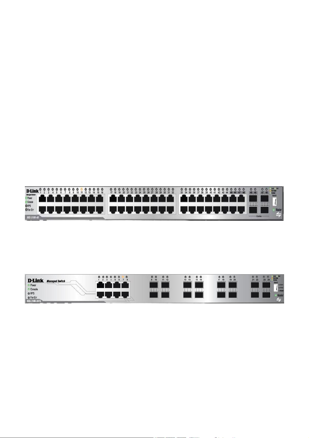
DGS-3100 Series Front Panel
The DGS-3100 series provides 24/48 high performance 1000BASE-T ports. The 1000Base-T por ts operate at 10/100/1000,
and connect to backbones, end-stations, and servers. The DGS-3100 series also provides 4 Mini-GBIC (SFP) co mbo ports
which connect fiber optic media to switches, servers, or network backbone. The DGS-3100 series provides an additional
RS-232 port (console port) for managing the switch via a console terminal or PC with a Terminal Emulation Program.
Figure 1 DGS-3100 Series 48 Port Front Panel
DGS-3100 Series Front Panel
The DGS-3100-24TG provides eight high performance 1000BASE-TX ports. The ports operate at 10/100/1000, and connect
to backbones, end-stations, and servers. The DGS-3100-24 TG also provides 16 Mini-GBIC (SFP) ports which connect fib er
optic media to switches, servers, or network backbone. The DGS-3100-24TG provide s an additional RS-232 port (console
port) for managing the switch via a console terminal or PC with a Terminal Emulation Program.
Figure 2 DGS-3100-24TG Front Panel
ii
Page 8

DGS-3100 Series Gigabit Stackable Managed Switch User Manual
Device Management Methods
The DGS-3100 series and DGS-3100-24TG provide dif ferent methods for managing the device including:
Web Based Management Interface
•
SNMP-Based Management
•
Command Line Console
•
Web Based Management Interface
Once the device is installed, network mangers can configure the switch, monitor the LED panel, and display statistics
graphically via a web browser, in cluding:
• Netscape Navigator (version 7.0 and higher)
• Microsoft® Internet Explorer (versi o n 5. 0) .
• Mozilla Firefox (version 2.0)
SNMP-Based Management
The system also supports SNMPv1, SNMPv2c, and SNMPv3. The SNMP agen t decodes the incoming SNMP messages,
and replies to requests with MIB objects stored in the database. The SNMP agent updates the MIB objects to generate
statistics and counters.
Command Line Console
The device also supports device configuration using the Command Line Interface. A terminal is connected to device via the
serial console port.
iii
Page 9

DGS-3100 Series Gigabit Stackable Managed Switch User Manual
User Guide Overview
This section provides an overview to the DGS-3100 series and the DGS-3100-24TG Switch Manual, including the guide
structure and a chapter overview:
• Section 1, Getting Started — Provides general background for understanding and using the Embedded Web
System, including an explanation of the interface buttons and general system functions.
• Section 2, Defining the Basic Device Configuration — Provides information for viewing system information,
defining IP addresses, managing stacking, defining ports, configuring SNMP management, and defining the system
time settings.
• Section 3, Configuring L2 Features — Provides information for enabling and configuring Jumbo frames, VLANs,
Trunks (LAGs), Traffic Segmentation, Multicast forwarding, and Spanning Tree.
• Section 4, Configuring Quality of Service — Provides information for ability to implement QoS and priority
queuing within a network.
• Section 5, Security Features — Provides information for enabling and configuring device security.
• Section 6, Monitoring the Device — Provides information for monitoring the device.
• Section 7, Managing Power over Ethernet Devices — Provides info rmation configuring the PoE function.
• Section 8, Defining Access Profile Lists — Provides information for configuring the ACL.
User Guide Overview
The DGS-3100 series/DGS-3100-24TG User Guide contains information for configuring and managing the DGS-3100
series/DGS-3100-24TG Switches. This guide is intended for network managers familiar with network management concep ts
and terminology.
Notes, Notices, and Cautions
NOTE: A NOTE indicates important information that helps you make better use of your device.
NOTICE: A NOTICE indicates either potential damage to hardware or loss of data and tells you
how to avoid the problem.
CAUTION: A CAUTION indicates a potential for property damage, personal injury, or death.
Safety Cautions
Use the following safety guidelines to ensure your own personal safety and to help protect your system from potential
damage. Throughout this safety section, the caution icon ( ) is used to indicate cautions and precautions that you need to
review and follow.
To reduce the risk of bodily injury, electrical shock, fire, and damage to the equipment, observe the following precautions.
iv
Page 10

DGS-3100 Series Gigabit Stackable Managed Switch User Manual
• Do not service any product except as explained in your system documentation. Opening or removing covers that
are marked with the triangular symbol with a lightning bolt may expose you to electrical shock. Only a trained
service technician should service components inside these compartments.
• If any of the following conditions occur, unplug the product from the electrical outlet and replace the part or
contact your trained service provider:
– The power cable, extension cable, or plug is damaged.
– An object has fallen into the product.
– The product has been exposed to water.
– The product has been dropped or damaged.
– The product does not operate correctly when you follow the operating instructions.
• Keep your system away from radiators and heat sources. Also, do not block the cooling vents.
• Do not spill food or liquids on your system components, and never operate the product in a wet environment. If the
system gets wet, see the appropriate section in your troubleshooting guide or contact your trained service provider.
• Do not push any objects into the openings of your system. Doing so can cause a fire or an electric shock by
shorting out interior components.
• Use the product only with approved equipment.
• Allow the product to cool before removing covers or touching internal components.
• Operate the product only from the type of external power source indicated on th e electrical ratings label. If you ar e
not sure of the type of power sour ce required, consult your service provider or local power co mpany.
• To help avoid damaging your system, be sure the voltage selection Switch (if provided) on the power supply is set
to match the power available at your location:
– 115 volts (V)/60 hertz (Hz) in most of North and South America and some Far Eastern countries such as South
Korea and Taiwan
– 100 V/50 Hz in eastern Japan and 100 V/60 Hz in western Japa n
– 230 V/50 Hz in most of Europe, the Middle East, and the Far East
• Also be sure that attached devices are electrically rated to operate with the power available in your location.
• Use only approved power cable(s). If you have not been provid ed with a power cable for your system or for any
AC-powered option intended for your system, purchase a power cable that is approved for use in your country. The
power cable must be rated for th e product and for the voltage and current marked on the product's electrical ratings
label. The voltage and current rating of the cable should be greater than the ratings marked on the product.
• To help prevent an electric shock, plug the system and peripheral power cables into properly grounded electrical
outlets. These cables are equipped with three-prong plugs to help en sure proper grounding. Do not use adapter
plugs or remove the grounding prong from a cable. If you must use an extension cable, use a 3-wire cable with
properly grounded plugs.
• Observe extension cable and power strip ratings. Make sur e that th e total ampere rating of all products plugged into
the extension cable or power strip does not exceed 80 percent of the ampere ratings limit for the ex tension cable or
power strip.
• To help protect your system from sudden, transient increases and decreases in electrical power, use a surge
suppressor, line conditioner, or uninterruptible power supply (UPS).
• Position system cables and power cables carefully; route cables so that they cannot be stepped on or tripped over.
Be sure that nothing rests on any cables.
• Do not modify power cables or plugs. Consult a licensed electrician or your power company for site modifications.
Always follow your local/national wiring rules.
• When connecting or disconnecting power to hot-pluggable power supplies, if offered with your system, observe the
following guidelines:
– Install the power supply before connecting the power cable to the power supply.
– Unplug the power cable before removing the power supply.
– If the system has multiple sources of power, disconnect power from the system by unplugging all power cables
from the power supplies.
v
Page 11
DGS-3100 Series Gigabit Stackable Managed Switch User Manual
Move products with care; ensure that all casters and/or stabilizers are firmly connected to the system. Avoid sudden stops
and uneven surfaces.
General Precautions for Rack-Mountable Products
Observe the following precautions for rack stability and safety. Also refer to the rack installation documentation
accompanying the system and the rack for specific caution statements and procedures.
Systems are considered to be components in a rack. Thus, "component" refers to any system as well as to various
peripherals or supporting hardware.
CAUTION: Installing systems in a rack without the front and side stabilizers installed could cause
the rack to tip over, potentially resulting in bodily injury under certain circumstances. Therefore,
always install the stabilizers before installing components in the rack.
After installing system/components in a rack, never pull more than one component out of the rack
on its slide assemblies at one time. The weight of more than one extended component could
cause the rack to tip over and may result in serious injury.
• Before working on the rack, make sure that the stabilizers are secured to the rack , extended to the floor, and that
the full weight of the rack rests on the floor. Install fro nt and side stabilizers on a single rack or front stabilizers for
joined multiple racks before working on the rack.
Always load the rack from the bottom up, and load the heaviest item in the rack first.
Make sure that the rack is level and stable before extending a component from the rack.
Use caution when pressing the component rail release latches and sliding a component into or out of a rack; the slide rails
can pinch your fingers.
After a component is inserted into the rack, carefully extend the rail into a lo cking position, and then slide the component
into the rack.
Do not overload the AC supply branch circuit that provides power to the rack. The total rack load should not exceed 80
percent of the branch circuit rating.
Ensure that proper airflow is provided to components in the rack.
Do not step on or stand on any component when servicing other components in a rack.
NOTE: A qualified electrician must perform all connections to DC power and to safety grounds. All
electrical wiring must comply with applicable local or national codes and practices.
CAUTION: Never defeat the ground conductor or operate the equipment in the absence of a
suitably installed ground conductor. Contact the appropriate electrical inspection authority or an
electrician if you are uncertain that suitable grounding is available.
CAUTION: The system chassis must be positively grounded to the rack cabinet frame. Do not
attempt to connect power to the system until grounding cables are connected. Completed power
and safety ground wiring must be inspected by a qualified electrical inspector. An energy hazard
will exist if the safety ground cable is omitted or disconnected.
vi
Page 12

DGS-3100 Series Gigabit Stackable Managed Switch User Manual
Protecting Against Electrostatic Discharge
Static electricity can harm delicate components inside your system. To prevent static damage, discharge static electricity
from your body before you touch any of the electronic components, such as the microprocessor. You can do so by
periodically touching an unpainted metal surface on the chassis.
You can also take the following steps to prevent damage from electrostatic discharge (ESD):
1. When unpacking a static-sensitive component from its shipping carton, do not remove the component from the
antistatic packing material until you are ready to install the component in your system. Just before unwrapping the
antistatic packaging, be sure to discharge static electricity from your body.
2. When transporting a sensitive component, first place it in an antistatic container or packaging.
3. Handle all sensitive components in a static-safe area. If possible, use antistatic floor pads and workbench pads and
an antistatic grounding strap.
Battery Handling Reminder
CAUTION: This is danger of explosion if the battery is incorrectly replaced. Replace only with the
same or equivalent type recommended by the manufacturer. Discard used batteries according to
the manufacturer's instructions.
vii
Page 13

DGS-3100 Series Gigabit Stackable Managed Switch User Manual
1
GETTING STARTED
To begin managing the device, simply run the browser installed on the management station and point it to the IP address
defined for the device. For example; http://123.123.123 .123. Please note that the proxy for session connection should be
turned off.
NOTE: The Factory default IP address for the Switch is 10.90.90.90.
This section contains information on starting the D-Link Embedded Web Interface. To access the D-Link user interface:
1. Open an Internet browser. Ensure that pop-up blockers are disabled. If pop-up blockers are enabled, edit, add, and
device information messages may not open.
2. Enter the device IP address in the address bar and press Enter.
Using the Web-Based User Interface
The user interface provides access to various switch configuration and management windows, allows you to view
performance statistics, and permits you to graphically monitor the system status.
DGS-3100-48 48 port device. The Web pages in the 24 port and the DGS-3100-24TG devices may vary slightly.
The screen captures in this Guide represent the
Understanding the D-Link Embedded Web Interface
The D-Link Embedded Web Interface Device Information Page contains the following information:
View Description
Tree View
Zoom View
Menu Information View
Device Information View
Stacking Status View
Displays the different system features, and configuration options.
Located at the top of the home page, the port LED indicators provide a visual
representation of the ports on the D-Link front panel.
Located below the Zoom View, displays Save, Tool menu, Stack ID, and Logout buttons. Also
displays Up Time information and User Loggin Identification.
Located in the main part of the home page, the device view provides a view of the
device, an information or table area, and configuration instructions.
Located at the bottom left corner of the home page, the stacking status view provides
a graphic representation of the stacking links and ports status.
Table 1-1. Web Interface Views
1
Page 14
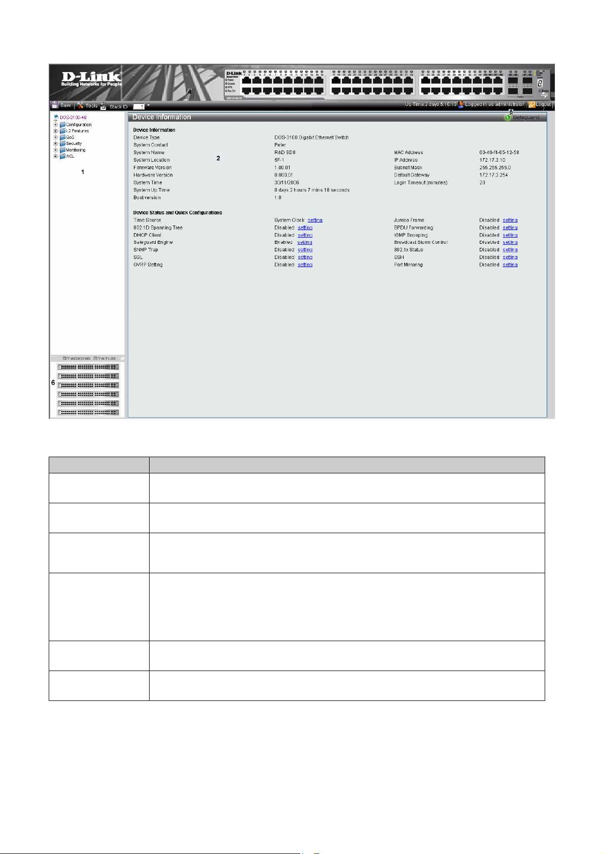
DGS-3100 Series Gigabit Stackable Managed Switch User Manual
Figure 1-1. Device Information Page
The following table describes the main 6 areas on the Device Information Page:
View Description
1. Tree View
Select the folder or window to be displayed. The folder icons can be opened to display the
hyperlinked menu buttons and subfolders contained within them.
2. Device
Presents Switch information based on the selection and the entry of configuration data
Information View
3. Menu
Information View
4. Zoom View
Presents the Save button, a menu for accessing device tools, and a menu for Stack ID
selection. The current
also here.
Up Time and current User Loggin information is reported. The Logout button is
Presents a graphical near real-time image of the front panel of the Swit ch . Thi s a rea di splays
the Switch's ports and expansion modules, showing port activity, duplex mode, or flow
control, depending on the specified mode.
Various areas of the graphic can be selected for performing management functions, including
port configuration
5 Device
Application Buttons
6 Stacking Status
Provides access to the device logout, and provides information about the Safe Guard mode
currently enabled on the device.
Provides a graphic representation of the stacking links and ports status.
View
Table 1-2. Main Areas
2
Page 15
DGS-3100 Series Gigabit Stackable Managed Switch User Manual
Using the Tool Menu
The tool menu contains menu options for:
Displaying the Stack Status
•
Locating Devices
•
Backing up and Restoring Configuration Files
•
Resetting the Device
•
Downloading the Firmware
•
Rebooting the System
•
Displaying the Stack Status
The Stacking Information Page provides specific information for stacked devices. For more information regarding the
stacking setup, see Managing Stacking section.
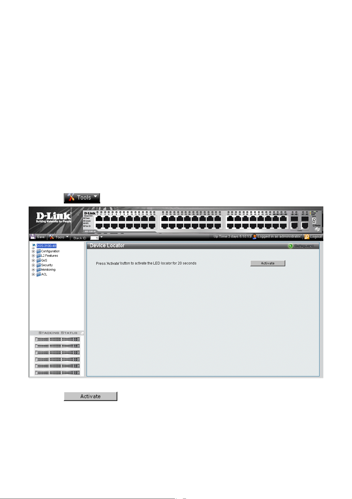
Locating Devices
The Device Locator Page enables locating system devices by activating LED locators. To locate devices:
1. Click
> Device Locator. The Device Locator Page opens.
3
2. Click
master unit.
Figure 1-2. Device Locator Page
. The LED locator is activated for 20 seconds On which the letter “L” will flash on the
Page 16
DGS-3100 Series Gigabit Stackable Managed Switch User Manual
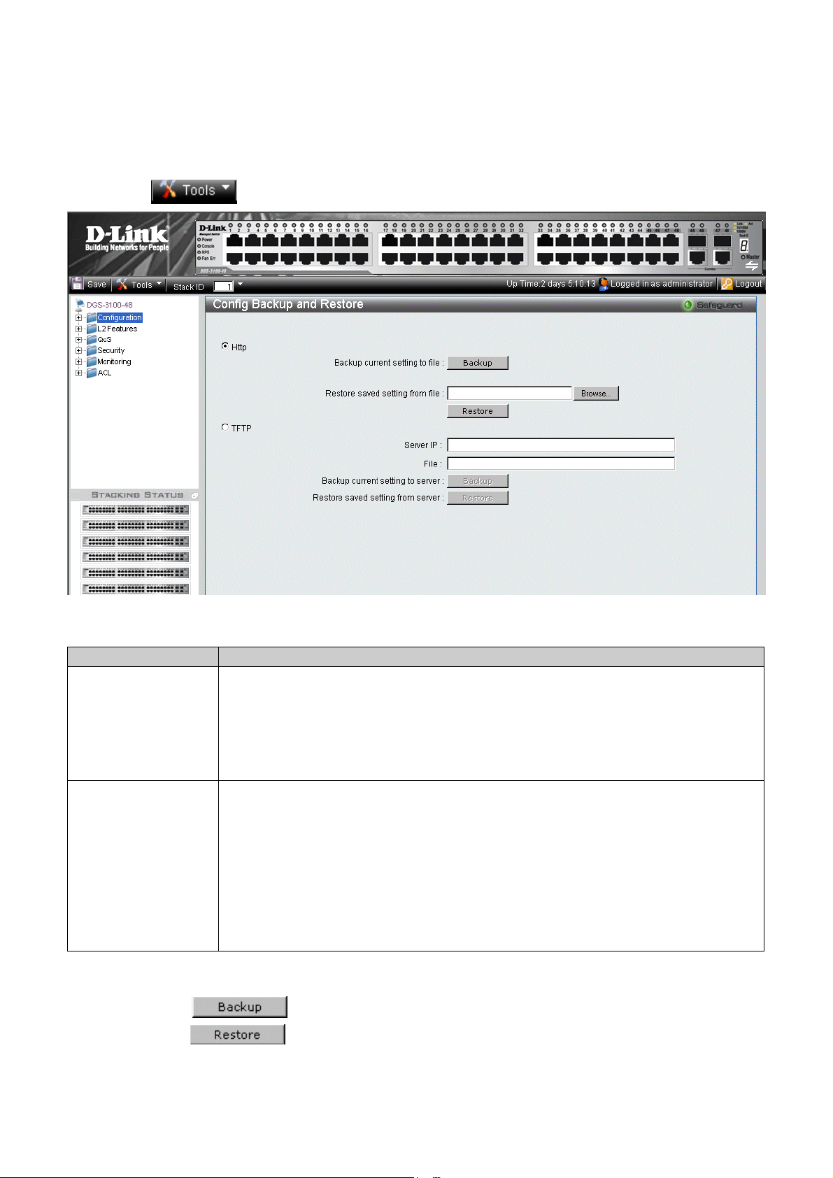
Backing up and Restoring Configuration Files
The Config Backup and Restore Page contains fields for downloading and uploading the configuration file from the device
through HTTP or TFTP server. To back up and restore configuration files:
1. Click
> Config Backup & Restore. The Config Backup and Restore Page opens.
Figure 1-3 Config Backup and Restore Page
The
Config Backup and Restore Page contains the following fields:
Field Description
Http
TFTP
2. Select HTTP or TFTP field.
3. Define the selected server method fields.
To backup files, click
To restore files, click
Indicates that the system files are backed up or restored via an HTTP server. The possible
field values are:
Backup current setting to file — Backs up the current configuration files via the HTTP
server.
Restore saved setting from file — Restores the current configuration files via the HTTP
server.
Indicates that the system files are backed up or restored via an TFTP server. The possible field
values are:
Server IP — Specifies the TFTP Server IP Address to which files are backed up or from
which they are restored.
File — Indicates the file that is backed up or restored.
Backup current setting to server — Backs up the current configuration files via the TFTP
server.
Restore saved setting from server — Restores the current configuration files via the TFTP
server.
.
.
4
Page 17
DGS-3100 Series Gigabit Stackable Managed Switch User Manual
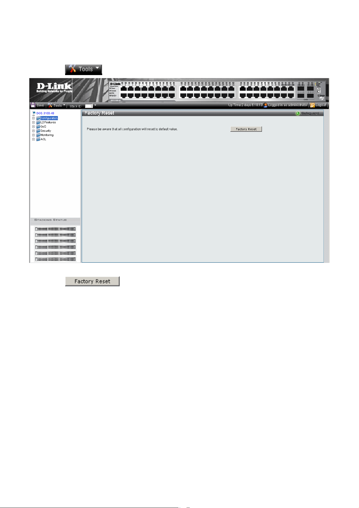
Resetting the Device
The Factory Reset Page restores the factory defaults. To restore the device to the factory default settings:
1. Click
> Reset. The Factory Reset Page opens:
2. Click
is updated.
Figure 1-4 Factory Reset Page
. The factory default settings are restored once it completely reloaded, an d the device
5
Page 18
DGS-3100 Series Gigabit Stackable Managed Switch User Manual
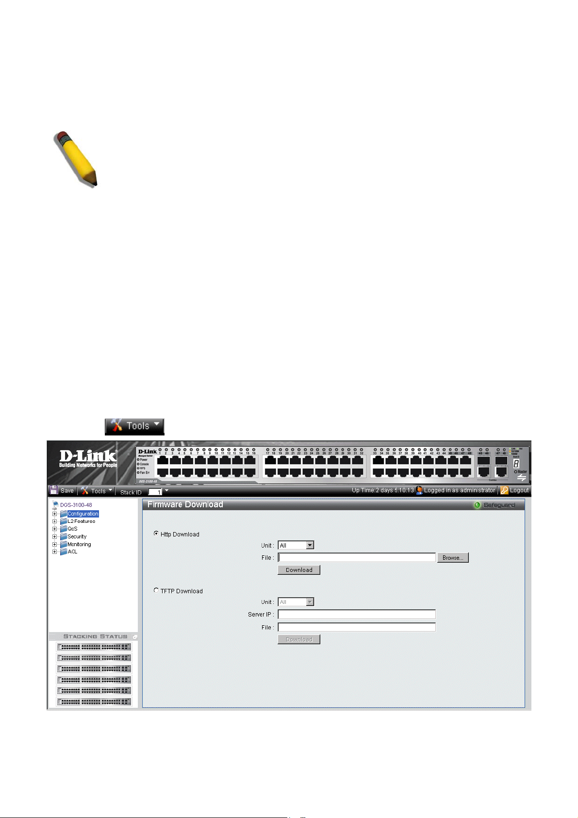
Downloading the Firmware
The ‘Firmware Download’ web page is used to download the firmware files that will be used to manage the device.
NOTE: Firmware version 1.x.x supports 4 SKUs od DGS-3100 series: DGS-3100-24, DGS-310024P, DGS-3100-48 and DGS-3100-48P, Firmware version 2.x.x supports in addition the 5
DGS-3100-24TG.
Firmware version 2.x.x includes as well additional features comparing to version 1.x.x, for more
details, please refer to the Release Notes.
When upgrading firmware from version 1.x.x to version 2.x.x on the switch, the user should
upgrade the boot software as well from version 1.0.0.3 to version 1.0.0.4
Upgrade Procedure – Important Note s:
ACL backward compatibility issue - In firmware 1.x.x, TCP/UDP ports of access profile are in hexadecimal instead of
decimal values. In version 2.x.x, TCP/UDP port value entries are in decimal value. However - if the user upgrades the
switch firmware from version 1.x.x to version 2.x.x, the value will be retained as hexadecimal value.
ACLs access rules priority did not work in firmware version 1.x.x. In firmware version 2.x.x, the priority is supported and it
is not allowed two identical access rules priority from different access profiles. If the user download configuration file from
version 1.x.x which including ACLs which has more than one rule, it might not work and there will be an error message.
The user can delete and create the ACLs again if he encountered a problem.
Tacacs/Radius backwards compatibility issue - In firmware version 1.x.x, it is possible to configure up to 4 Tacacs /Radius
servers. In firmware version 2.x.x, it is possible to configure up to 3 servers from each type. In addition to that it was not
required to configure priority to Tacacs server s in 1.x.x while in 2.x.x it is required. If the user configured 4 servers in
version 1.x.x and try to download the configuration to firmware 2.x.x, he will get an error message, the same event will
happened because of the Tacacs priority.
The
Firmware Download Page enables downloading files either via an HTTP or a TFTP server. To download Firm ware:
th
SKU:
1. Click
> Firmware Download. The Firmware Download Page opens:
Figure 1-5 Firmware Download Page
6
Page 19

DGS-3100 Series Gigabit Stackable Managed Switch User Manual
The
Firmware Download Page contains the following fields:
Field Description
HTTP Download
Indicates that the Firmware file is downloaded via an HTTP server.
Unit — Indicates if the Firmware file is downloaded to a specific stacking member or to
All stacking members.
File — Indicates the Firmware file that is downloaded to the stack or specific device.
TFTP Download
Indicates that the Firmware file is downloaded via a TFTP server .
Unit — Indicates if the Firmware file is downloaded to a specific stacking member or to
All stacking members.
Server IP Address — Specifies the TFTP Server IP Address from which files are
downloaded.
File — Indicates the Firmware file that is downloaded to the stack or specific device.
2. Select HTTP or TFTP Download field.
3. Define the Unit field.
4. For Http download, define the File field, or alternatively, browse to select the file.
5. Click
. The Firmware is downloaded, and the device is updated.
7
Page 20
DGS-3100 Series Gigabit Stackable Managed Switch User Manual
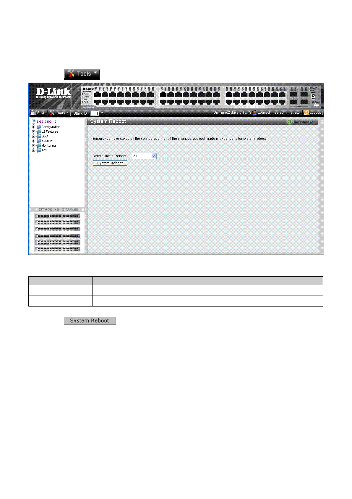
Rebooting the System
The System Reboot Page provides a method for selecting one, or all of the units to be rebooted. To reboot the system:
1. Click
> System Reboot. The System Reboot Page opens:
Figure 1-6 System Reboot Page
The
System Reboot Page contains the Select Unit to Reboot field. The possible values are:
Value Description
All
01 - 06
2. Define the Select Unit to Reboot field.
3. Click
Reboots all stacking members.
Reboots the specific stack member.
. The selected unit(s) is/are rebooted.
8
Page 21
DGS-3100 Series Gigabit Stackable Managed Switch User Manual
Using the Web System Components
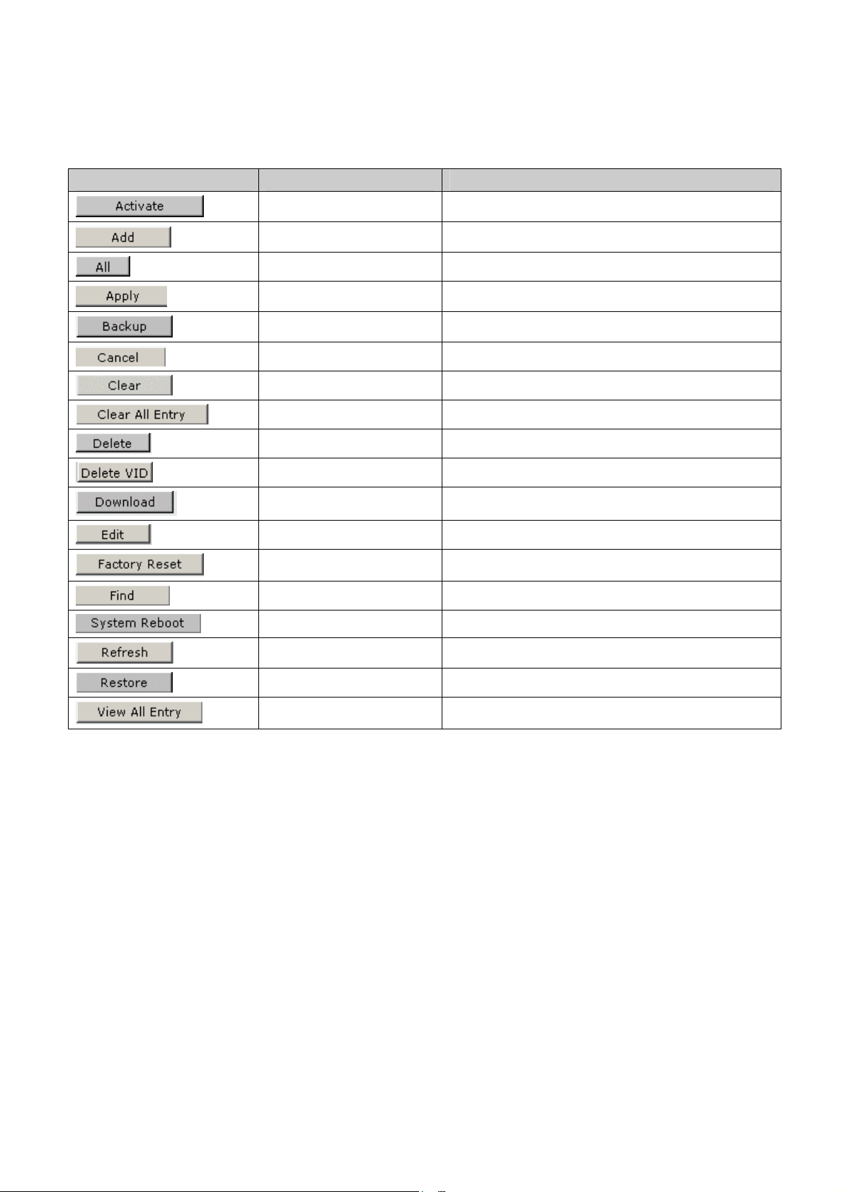
The following table contains information regarding the list of buttons:
Name Description Component
Activate Activates field commands
Add Adds selected items
ALL Selects all
Apply Applies field settings
Backup Evokes backup
Cancel Cancels settings
Clear Clears selected settings and fields
Clear All Clears all settings and fields
Delete Deletes selected fields
Delete VID Deletes VLAN Identification
Download Starts downloading system files.
Edit Modifies configuration Information
Factory Reset Resets the factory defaults
Find Finds a table entry.
System Reboot Reboot the system
Refresh Refreshes device information.
Restore Restores the specific configuration file.
View All Entry Displays table entries.
Table 1-3. User Interface Buttons
9
Page 22

DGS-3100 Series Gigabit Stackable Managed Switch User Manual
2
CONFIGURING BASIC CONFIGURATION
This section contains information for viewing device information, defining IP addresses, managing stacking, defining port
parameters, configuring system user accounts, configuring and managing system logs, defining the system time, and
configuring SNMP system management. This section contains the following topics:
Viewing Device Information
•
Defining System Information
•
Defining IP Addresses
•
Managing Stacking
•
Defining Ports
•
ARP Settings
•
Configuring User Accounts
•
Managing System Logs
•
Configuring SNTP
•
Configuring SNMP
•
DHCP Auto Configuration
•
Dual Image Services
•
10
Page 23
DGS-3100 Series Gigabit Stackable Managed Switch User Manual
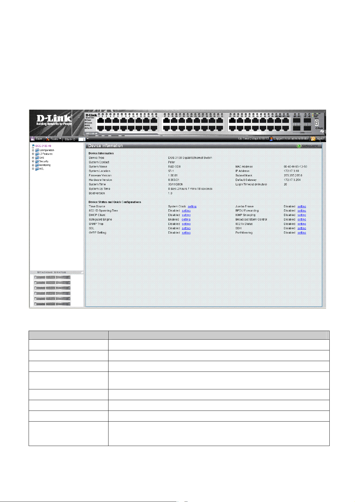
Viewing Device Information
The Device Information Page contains parameters for configuring general device information, including the system name,
location, and contact, the system MAC Address, System Up Time, and MAC addresses, and both software, boot, and
hardware versions.
In addition the
information:
• Click
Device Information Page provides shortcuts to device feature pages. To define the general system
DGS-3100-xx in the Tree View. The opens: Device Information Page
Figure 2-1 Device Information Page
The
Device Information Page contains the following fields:
Field Description
Device Type
System Contact
System Name
System Location
Firmware Version
Hardware Version
System Time
System Up Time
11
Displays the factory defined device name and type.
Displays the name of the contact person. The field range is 0-31 characters.
Displays the user-defined system name. The field range is 0-31 characters.
Displays the location where the system is currently running. The field range is 0-31
characters.
Displays the installed software version number.
Displays the installed device hardware version number.
Displays the system time. The field format is Day/Month/Year.
Displays the amount of time since the most recent device reboot. The system time is
displayed in the following format: Days, Hours, Minutes, and Seconds. For example, 41
days, 2 hours, 22 minutes and 15 seconds.
Page 24

Field Description
Boot Version
Displays the installed device boot version number.
DGS-3100 Series Gigabit Stackable Managed Switch User Manual
MAC Address
IP Address
Subnet Mask
Default Gateway
Login Timeout (minutes)
Time Source
802.1D Spanning Tree
DHCP Client
Safeguard Engine
SNMP Trap
SSL
GVRP Setting
Jumbo Frames
Displays the MAC address assigned to the device.
Displays the IP address assigned to the device.
Displays the subnet mask assigned to the device.
Displays the device default gateway assigned to the device.
Indicates the amount of time after which if no user activity occurs, the device times out.
The default is 10 minutes.
Provides a shortcut to viewing the system clock settings.
Indicates if STP is enabled on the device, and provides a shortcut to viewing the STP
settings.
Indicates if DCHP Client is enabled on th e device, and provides a shortcut to viewing the
DHCP Client settings.
Indicates if the Safeguard Engine is enabled on the device, and provides a shortcut to
viewing the Safeguard Engine settings.
Indicates if SNMP Traps are enabled on the device, and provides a shortcut to viewing
the SNMP Traps settings.
Indicates if Secure Socket Layer (SSL) is enabled on the device, and provides a shortcut
to viewing the SSL settings.
Indicates if Group VLAN Registration Protocol is enabled.
Indicates if Jumbo Frames are enabled on the device, and provides a shortcut to viewing
the Jumbo Frames settings.
BPDU Forwarding
Indicates if BPDU Forwarding is enabled on the device, and provides a shortcut to
viewing the BPDU Forwarding settings.
IGMP Snooping
Indicates if IGMP Snooping is enabled on the device, and provides a shortcut to viewing
the IGMP Snooping settings.
Broadcast Storm Control
Indicates if Broadcast Storm Control is enabled on the device, and prov ides a shortcut to
viewing the Broadcast Storm Contro l settings.
802.1X Status
Indicates if 802.1X is enabled on the device, and provides a shortcut to viewing the
802.1X settings.
SSH
Indicates if Secure Shell Protocol (SSH) is enabled on the device, and provides a shortcut
to viewing the SSH settings.
Port Mirroring
Indicates if Port Mirroring is enabled.
To view settings for a device feature:
1. Select a device feature under the Device Status and Quick Configuration Section.
2. Click setting next to the feature name. The configuration page for the selected device feature opens.
12
Page 25
DGS-3100 Series Gigabit Stackable Managed Switch User Manual
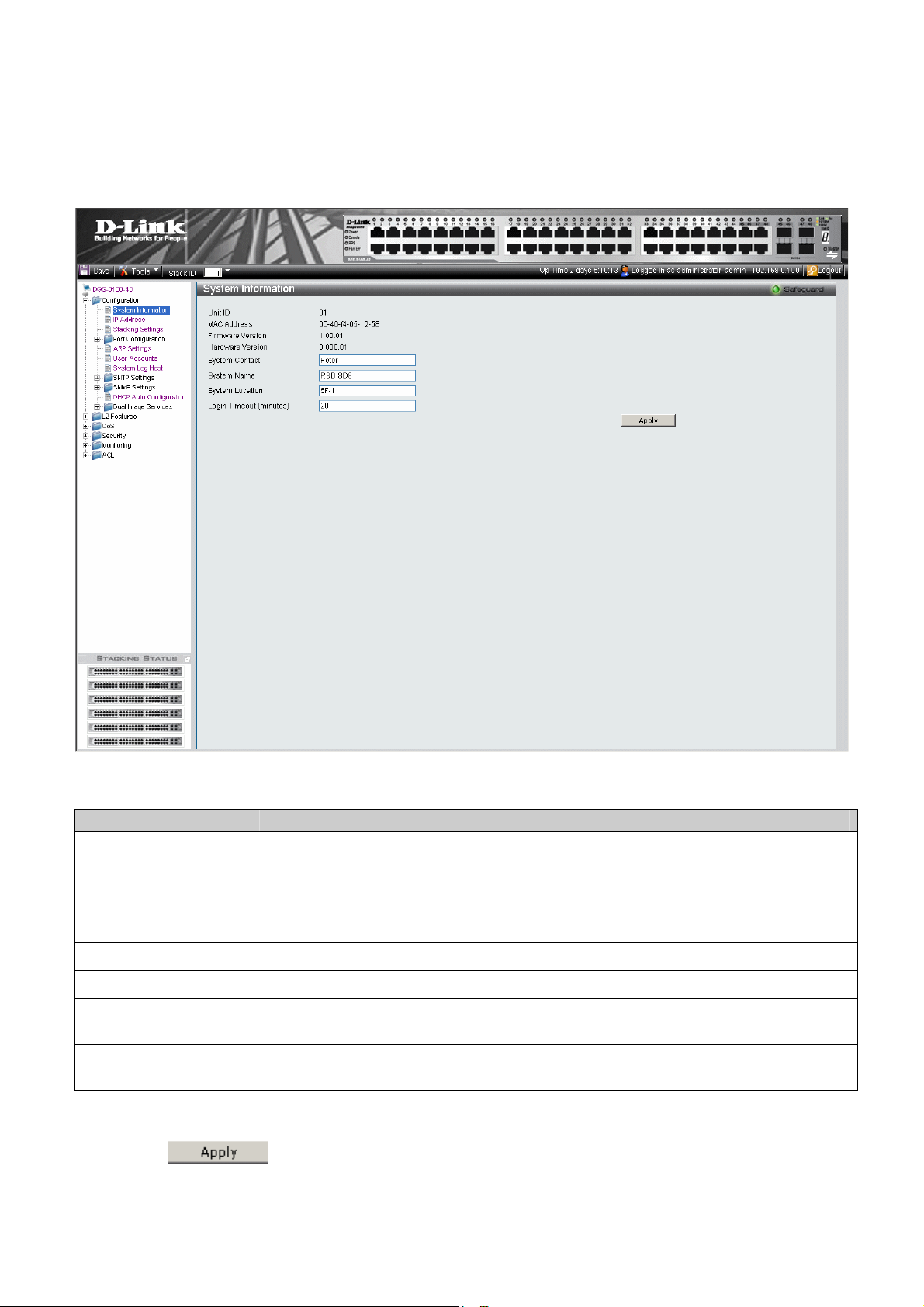
Defining System Information
The System Information Page provides device information about specific stacking members. To view system information:
1. Click
Configuration > System Information. The System Information Page opens:
Figure 2-2 System Information Page
The
System Information Page contains th e following fields:
Field Description
Unit ID
MAC Address
Firmware Version
Hardware Version
System Contact
System Name
System Location
Login Timeout (minutes)
2. Define the System Name field.
3. Define the System Location and Login Timeout (minutes) fields.
4. Click
13
Displays the stack unit ID.
Displays the MAC address assigned to the device
Displays the stacking memb er’s software version number.
Displays the stacking member’s hardware version number.
Defines the name of the contact person. The field range is 0-160 characters.
Defines the user-defined system name.
Defines the location where the system is currently running. The field range is 0-160
characters.
Defines the amount of time the device times out when no user activity occurs. The default is
10 minutes.
. The system information is defined, and the device is updated.
Page 26
DGS-3100 Series Gigabit Stackable Managed Switch User Manual
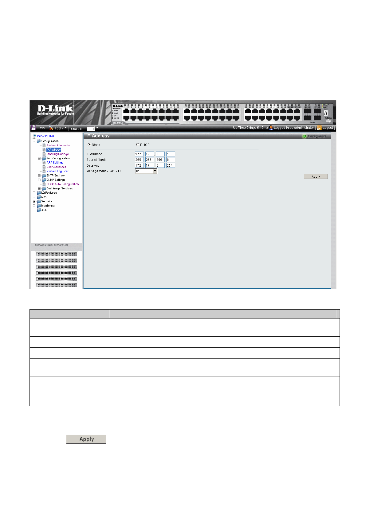
Defining IP Addresses
The IP Address Page contains fields for assigning IP addresses. Packets are forwarded to the default IP when frames are
sent to a remote network via the Default Gateway. The configured IP address must belong to the same IP address subnet of
one of the IP interfaces. The Dynamic Host Configuration Protocol (DHCP) assigns dynamic IP addresses to devices on a
network. DHCP ensures that network devices can have a different IP address every time the device connects to the network.
1. Click Configuration > IP Address. The IP Address Page opens:
Figure 2-3 IP Address Page
The
IP Address Page contains the following fields:
Field Description
Static
DHCP
IP Address
Subnet Mask
Gateway
Management VLAN VID
2. Select the IP address type in either the Static or DHCP fields.
3. If Static is the defined IP address type, define the IP Address field.
4. Define the Subnet Mask, Gateway, and Management VLAN VID fields.
5. Click
When selected, the IP address is static and user-defined in the IP Address field. This is the
default value.
When selected, the IP address is retrieved from a DHCP server.
Defines the IP address. This field is active if the IP address is static.
Defines the address mask that manages sub-netting on the network. The default value is
255.0.0.0.
Defines the default gateway. The default gateway manages connections to other subnets
and other networks.
Defines the management VLAN’s VID.
. The IP address information is defined, and the device is updated.
14
Page 27

DGS-3100 Series Gigabit Stackable Managed Switch User Manual
Managing Stacking
Stacking enhances network flexibility by building virtual switches with more ports then are available in a single device.
Stacks are managed by stacking member which called Stack Master., All ot her stacking members serve as ports only.
The following paragraphs provide a stacking explanation for DGS-3100 series and include the following topics:
Managing Stacking Modes
•
Advanced Stacking
•
Building Stacks – Quick Start
•
Stack Management Examples
•
Configuring Stacking
•
Managing Stacking Modes
A switch may operates in one of the following modes:
• Stand-Alone- Switches operating in stand-alone mode run as an independent unit. All ports of a stand-alone switch
operate as normal Ethernet links except the HX ports which are Disabled.
NOTE: The DGS-3100 series family stacking connections have two HX ports.
• Stacking - Switches operating in Stack mode run as organized group me mber of switches known as a Stack. A
stack consists of one Stack Master, a Backup Master, and up to four Stack Member Switches. However, in specific
scenarios, a single unit can be considered a Stack of One. A Stack of One is a single unit which does not connected
to any other stacking members.
Either stacking or stand-alone modes can be selected by the user before the next software boot which using CLI or the
Embedded WEB Interface, the new mode takes effect after the unit is rebooted. If the unit is reset to the factory defaults, the
unit is reloaded in stacking Auto-Numbering mode.
Advanced Stacking
This section provides information for understanding advanced stacking concepts, including:
• Unit ID and how they are allocated
• Stacking member start up process.
This section contains the following topics:
Allocating Unit IDs
•
Assigning Unit IDs
•
Allocating Unit IDs
Switches are shipped from the factory without a Unit ID and in Auto Assign mode. All switches must be assigned a Unit ID
before switches can operate as stacking members. More than one stacking member cannot receive the same Unit ID. Unit
IDs are assigned by:
• Assigned by the system administrator. Unit IDs that are assigned by the system administrator and can only be
changed manually by the system administrator.
• If the system administrator does not set the Unit IDs manually, the Auto Assign initializes the switches when they
are powered up. From the switches who are automatically assigned a Unit ID, one of the stacking members is
assigned the Unit ID 1. That stacking member is the Stack Master. If there were more than one switch in the stack,
there is a Master Election and Backup Master Election process. Following the Master Election process, the other
stacking members are assigned a Unit ID by the stack Master. For more information on the Master Election process,
please see
Electing a Stacking Master.
15
Page 28

DGS-3100 Series Gigabit Stackable Managed Switch User Manual
Stacking members maintain the assigned Unit ID even after the stacking member is rebooted. The Stack Master may
reallocate IDs during system initialization to resolve duplicate ID conflicts. Manually assig ned IDs cannot be changed by
the Stack Master, even if there is a conflict.
Unit ID assignments or modifications are effective only during system initialization, and do not occur during the system uptime.
Stacking members do not have to be numbered in sequence, and can be interconnected, as long as each stacking has a
unique ID, and at least, one stacking member serves as the Stack Master.
Assigning Unit IDs
Each stacking member has an assigned unique Unit ID. Unit ID numbers are assigned as follows:
• Unit ID 1 - Assigned to the Stack Master. The Stack Master is indicated by the Master LED on front which is lit
solid green.
• Unit ID 2 - Assigned to the Backup Master
• Unit ID 3, 4, 5, and 6 - Assigned to Stacking members.
NOTE: There are cases in which a unit to which Unit ID 1 is assigned is not the stack Master but a
Backup Master.
This section contains the following topics:
•
Defining a Stacking Master
Defining a Stacking Back Up Master
•
Defining Stacking Members
•
Master Enabled Stacking Members
•
Electing a Stacking Master
•
Defining a Stacking Master
The stacking member assigned the Unit ID1 operates as the Stack Master.
The Stack Master provides a single point of control, configuratio n, and management for the entire stack. In addition, the
Stack Master stores all stack member configuration. The individual stacking members do not store any configuration
information.
Defining a Stacking Back Up Master
The stacking member assigned the Unit ID 2 is defined as the stack’s Backup Master.
In addition to being a stack member, Backup Master serves as a backup in case the Stack Master fails or disconnected. If the
Stack Master fails or disconnected, the Backup Master takes over as the Stack Master.
The Stack Master stores an active configuration which copied on the Backup Master. The active configuration copy is used
if the Backup Master takes over for the Stack Master. Only the configuration file is copied. Any dynamically filled tables,
for example, learnt address, are not copied from the Stack Master to the Backup Master. If the Backup Master takes over the
role of Stack Master, the Backup Master builds new dynamic tables.
Defining Stacking Members
Switches assigned the Unit IDs 3,4,5,6 are called stacking members. The Stack Master (or Backup Master if the Stack
Master fails) manages the stack members operation. Stacking members cannot be directly managed or configured. If neither
the Stack Master nor the Backup Master were operating, the stacking members cannot function.
Master Enabled Stacking Members
Only Stacking members assigned to Unit ID 1 or 2 are called Master Enabled stacking members. Only the Master Enabled
stacking members participate in the Master Election process, and therefore can become master or backup master (that means
the s with assigned IDs of 3, 4, 5 and 6 can never become neither a master nor a backup master unless their ID is changed by
the system administrator or reset to the factory default firstly).
16
Page 29

DGS-3100 Series Gigabit Stackable Managed Switch User Manual
Electing a Stacking Master
Whenever a stack ing member ( or more than one) co mes up, one of the stacking members is elected to be the stack Master.
The Stack Master is selected as follows:
• If one of the master enabled stacking members in the stack was set to Force Master by the system administrator
(through the GUI – Stacking Master selector), that master enabled stacking member is the Stack Master. Stacking
members which are defined as Force Master stacking members are manually selected as the Stack Master. Only a
master enabled stacking member can be selected as the Force Master.
• If the stack contains more than one stacking member whose Unit ID is either 1 or 2, then one of the stacking
members are elected the Stack Master. It does not matter if the Unit ID was originally automatically or manually
assigned. These stacking members are called Master Enabled. If there is only one stacking member, that stacking
member is selected as the Stack Master, even if the stacking member’s Unit ID is 2.
• If there are more than one stacking members, the two stacking members decide which stacking member is elected
Stack Master by checking:
– Which stacking member has been running for a longer time. The up-time is measured in increments of 10
minutes. The stacking member running the longest is elected the Stack Master.
– If they have been running for the same amount of time, the stacking member with the Unit ID 1 is the stack
Master.
– If both stacking members have been running for the same amount of time, and both stacking membes have the
same Unit ID, the stacking members with the lowest MAC addressis selected as the Stack Master. The other
unit is rebooted and is assigned the Unit ID 2.
– If the stack contains one or more stacking members set to the factory default states, and there is no Unit ID
assigned to a stacking member, then the Stack Master is one of these stacking members. The stacking member
selected to be the Master is the stacking member running for the longest time. If all stacking members are
running the same amount of time, the stacking member with the lowest MAC address is selected as the Stack
Master.
The Master Election results in an elected Stack Master. The Stack master has a Unit ID of 1 and the Backup Master has a
Unit ID of 2 (if a Backup Master was included in the stack).
If a Master Enabled stacking member, a Unit ID of 1 or 2, is added to a stack and powered on, the newly added switch
invokes Master Election process. The Master Election process occurs even though the stack has an elected master. However,
the newly added switch loses in the election process (lower up-time) and joins the stack as a stacking member or Backup
Master.
Stack Startup Process
When a stacking member is initialized, either powered up or rebooted, the stacking member goes through the same exact
process including:
Discovering the Stacking Master.
•
Allocating Unit IDs/Resolving Unit ID Conflicts
•
Unit and Stacking Port Configuration
•
Discovering the Stacking Master
When a stacking member is initialized in stack mode, the stacking member’s behavior depends on its Unit ID.
• If the stacking member does not have a current Unit ID the stacking member operates in Factory Default mode. If
there is a Stacking Master, the stacking member is assigned a Unit ID through Unit ID Allocation. The stacking
members receive a Unit ID from the Stacking Master. If the stack does not have a Stacking master then the switch
participates in Master-Election, and may be elected either the new Stacking Master or Backup Master.
• If the stacking member’s current Unit ID is 1 or 2, the stacking member participates in the Master Election. For
example, the Unit ID was previously allocated, or the stacking member was in a different stack.
• If the stacking member has a current Unit ID the stacking members attempts to use the Unit ID in the new stack. If
the stacking member current ID is 3, 4, 5, or 6, then the stacking members attempts to connect to the running Stack
Master. The new stacking member does not proceed to the next stage until there is contact with the Stack Master.
17
Page 30

DGS-3100 Series Gigabit Stackable Managed Switch User Manual
These stacking members do not participate in the Master Election process, and if no Stack Master is present, the
stacking members’ network ports are shut down. Only the stacking ports are operational.
Both the Stack Master and all other stacking members carry out a continuous process of Master Discovery by frequently
exchanging stack control messages. This allows the stacking members to discover when a stacking member fails or is
unreachable.
Allocating Unit IDs/Resolving Unit ID Conflicts
Once the Stack Master is elected, it allocates the Unit IDs to the stacking members that do not have a Unit ID. Stacking
members that do not have a Unit ID operate in the Factory Defau lt mode.
In addition, the stack Master attempts to resolve all duplicate Unit IDs occurrences among stacking members. The Stack
Master reallocates the duplicate Unit ID if there are available Unit IDs.
If two stacks are merged, stacking units that were initially in the Stack Master’s sub-group retain their Unit ID. New
stacking member are allocated new Unit IDs.
If a conflict occurs after the stacking members are rebooted, the following occurs:
• If both duplicate stacking members are in Auto Assign mode, then the Unit ID is assigned by the MAC address.
The stacking member with the lowest MAC address maintains its Unit ID. The other stacking member is assigned a
new Unit ID.
• If one of the stacking members with duplicate Unit IDs is in Auto Assign mode and the other stacking member is in
manual mode, the stacking member in Manual mode maintains its Un it ID, The other stacking member is assigned
a new Unit ID. .
Stacking members are shut down if:
• If both duplicate stacking members are in Manual mode then both stacking members are shut down.
• If the Stack Master is able to allocate a Unit ID to each stacking me mber, then all stacking members operate as a
stack. If the Stack Master is unable to allocate a Unit ID to any stacking member, that stacking member is
effectively shut down and does not participate in the stack.
• Stacking members with a conflicting manually set ID are shut down as the Stack Master cannot override the system
administrator’s Unit ID assignment to resolve the conflict.
• If there are more stacking members than the maximum number allowed in a stack, and the incoming stacking
members are already in Factory Default mode, the Stack Master is elected following Master Discovery and Master
Election processes. All other stacking members are shut down in some extreme cases, due to during the boot
process, where some stacking members may be connected an d join the stack. If the new stacking members are
already assigned a Unit, then the new stacking members cannot join the stack. The switches are remains shut down.
If a stacking member is shut down, the stacking members stacking links are inactive. Moreover, if the stacking members are
connected in a chain topology, the shut down of one stacking member break s the chain. This may cause other stacking
members to be disconnected and shut down if the stacking members have no active link to the Stack Master.
Unit and Stacking Port Configuration
Each stacking member has a Unit ID; one of the stacking members is the stack Master, and, possibly, one of the stacking
members serves as Backup Master. The Stack Master now configures each stacking member according to the Configuration
file stored on the Stack Master.
If the stack has a Backup Master the Configuration file are also be copied to the Backup Master.
Once all the stacking members are configured, the stack proceeds to a normal operational mode. If any change is made to
the system configuration, the change is stored by the stack Master and is copied to the Backup Master.
18
Page 31

DGS-3100 Series Gigabit Stackable Managed Switch User Manual
Building Stacks – Quick Start
The DGS-3100 series supports the following stacking scenarios:
• Building a new stack from scratch
• Increasing the stack by adding units to an existing stack
This section contains the following topics:
Stack Resiliency
•
Managing a Self-Ordered Stack
•
Managing a New Manually Ordered Stack
•
Stack Resiliency
Topologies of stack can be either Ring or Chain. Best practice is to configure the stack in Ring topology, due to the high
resiliency in case of unit failure or stacking link failure.
Additionally, in case of redundant power supply usage it is recommended to make sure that Master and Backup Master s are
connected to a redundant power supply.
Managing a Self-Ordered Stack
This section describes managing a self-ordered stack. Self–ordered stacks are automatically assigned Unit IDs by the system
through the Master Election process. This section contains the following topics:
Building a New Self-Ordered Stack
•
Adding Members to a Self Ordered Running Stack
•
Building a New Self-Ordered Stack
To build a self ordered stack:
1. Connect the units physically through the stacking ports.
2. Turn on the units. After a short interval the stack will become operational with one of the units selected as the
Master of the stack. The Master and Backup selection is known as Ma ster Election. Master Election takes place if
there are one or more eligible candidates contending to be the Master unit. The Master Unit is indicated by the
green Master LED on the front panel. The Master LED is located near the Unit ID LEDs. If a serial console is
connected, the serial cable must be connected to the Stack Master console port since the only operational console
port in the stack is the one of the Master unit.
NOTE: To reset the stacking members to the factory defaults, press the Reset button for at least 5
seconds.
Adding Members to a Self Ordered Running Stack
1. Reset the new stacking units to the factory defaults by pressing the Reset button (optional).
2. Connect the stacking members physically to the stack.
3. Turn on the switches, the new units will become stacking members.
Managing a New Manually Ordered Stack
System administrator can also manually assign Unit IDs to stacking members. System administrator has to assign a unique
Unit ID from 1 to 6 to each stack member.
A Unit ID that is manually assigned is not subject to automatic numbering. The Unit IDs are assigned as follows:
• Unit ID 1 – Assigned to the Stacking Master. The Stack Master is indicated by the Master LED on front which is
lit solid green.
• Unit ID 2 - Assigned to the Backup Master
• Unit ID 3 4, 5, 6 –Assigned to the Stacking member.
19
Page 32

DGS-3100 Series Gigabit Stackable Managed Switch User Manual
This section contains the following topics:
Building New Manually Ordered Stacks
•
Adding Stacking Members to an Existing Manually Ordered Stack
•
Building New Manually Ordered Stacks
To build new a self ordered stack:
1. Connect the units physically through the stacking ports.
2. Turn on the units, one at a time.
3. Assign the Stack Master the Unit ID of 1 using a Stack Management Interfaces either the console port, Telnet, or
Embedded Web Interface.
4. Assign the Backup Master the Unit ID of 2 using a Stack Management Interfaces either the console port, Telnet, or
Embedded Web Interface.
5. Assign the remaining stacking members using a Stack Management Interfaces either the console port, Telnet, or
Embedded Web Interface.
6. Ensure that none of the stacking members have the same Unit ID.
7. Reboot all the stack units.
Adding Stacking Members to an Existing Manually Ordered Stack
To add units to an existing manually ordered stack:
1. Reset the new stacking units to the factory defaults by pressing the Reset button.
2. Connect the stacking members physically to the stack.
3. Turn on the switches, the new units become stacking members, but with automatically assigned Unit IDs.
4. Reassign the Unit ID manually to each of the newly added stacking members using a Stack Management Interfaces
either the console port, Telnet, or Embedded Web Interface. This step is optional, and the stack is operational even
if some unit IDs were manually configured while others are self-assigned.
5. Reboot the stacking members to ensure the Unit ID is permanent.
Stack Management Examples
This section contains information for troubleshooting stacking, and includ es the following topics:
Replacing Failed Stacking-Members in a Running Stack
•
Replacing a Failed Stack Master
•
Dividing Stacks
•
Merging Stacks
•
Stacking Cable Failure
•
Inserting Excess Stacking Members
•
Replacing Failed Stacking-Members in a Running Stack
This example assumes that a stacking member, other than master, has failed in a running stack, when the system
administrator is notified of the system failure the stacking member is removed and replaced with a new switch.
When the stacking member fails, the Stack Master identifies the failed stacking member using the Master Discovery process.
The Stack Master recognizes that the stacking member no longer responds. If the stack topology was ring topolog y, the
Stack Master directs all other stack members to route traffic around the failed stacking member. At the same time the Stack
Master notifies the system administrator of the failure using SYSLOG messages and SNMP traps.
When the failed stacking member is disconnected from the stack, all traffic is ro uted around the failed stacking memb er as
stated above. As long as all other stacking connections are intact, the stack continues to run.
When a new stacking member is inserted and the stack is powered up, the following occurs:
• The new stacking member which is in stacking mode, performs the Master Discovery process, and perhaps
participates in a Master Election .For more information on the Master Election process, see
.
Master
Electing a Stacking
20
Page 33

DGS-3100 Series Gigabit Stackable Managed Switch User Manual
– If the new stacking member has a Unit ID of 1 or 2, i.e. the stacking member is a master enabled unit, the new
stacking member initiates the Master Election process. However, since the running Stack Master has a longer
up-time, it remains the Stack Master and the new stacking member does not become a new Stack Master.
– If the new stacking member has a Unit ID of 3 to 6, the new unit attempts to become a stacking member, and
is subject to the already running Stack Master. The Master Election process does not occ ur.
• The Stack Master performs a Unit ID Allocation and Conflict Resolution process.
– If the new stacking member was in Factory Default mode (the unit does not have an assigned Unit ID). The
new stacking member is assigned the lowest available Unit ID by the Stack Master. It is strongly
recommended that automatic assigned Unit ID mode be used since it provides improved stack resiliency.
– If the new stacking member already has an assigned Unit ID, and that Unit ID is unused in the current stack ,
the new stacking member retains its assigned Unit ID. The Stack Master applies any configuration relevant to
that Unit ID.
– If the new stacking member already has an assigned Unit ID, an d that Unit ID conflicts with an existing Unit
ID the Stack Master reallocates a new Unit ID to the new stack ing member. , The lowest available Unit ID is
applied to the new stacking member. This occurs only if new stacking member does not have a manually
assigned Unit ID, which the Stack Master cannot change.
– If the new stacking member cannot be assigned an available Unit ID, then the new stacking member is
effectively shut down and cannot join the stack. For example, the stacking member replacement can only occur
if the new stacking member has a manually assigned Unit ID.
• The Stack Master now performs
• Any configuration information which the Stack Master stores that is relevant to the Unit ID is assigned to the new
stacking member. If the new stacking member was assigned the same Unit ID of the replaced stackin g member,
then the new stacking member receives the same configuration as the failed stacking me mber. If the new stacking
member is identical to the replaced stacking member, the entire configuration of the replaced stacking member is
applied to the new stacking member. The stack reverts to the stacking state it was running in before stacking
member failed. However, sometimes the new stacking member is not identical to th e failed stacking member. The
Stack Master applies the configuration as follows:
• If a 24-port switch replaces a failed 48-port switch, then the new stacking member’s ports are configured according
first 24 ports configuration of the failed stacking member.
Unit and Stacking Port Configuration for the new stacking member.
NOTE: The 48 port configuration of the failed stacking member is recorded, even though only the
first 24 port configuration is currently applied. If a 48 port switch is inserted and assigned the
same Unit ID, the switch is configured with the port configuration of the original 48 port stacking
member.
• If a 48-port stacking member replaces a 24-port stacking member, then the first 24 ports of thenew stacking
member are configured according failed stacking member’s ports configuration. The remaining new stacking
member ports are configured with the switch’s default settings.
Replacing a Failed Stack Master
This example assumes that that a stacking member acting as the Stack Master has failed in a running stack. When the
system administrator is notified of the Stack Master failure and replaces existing Stack Master with a new switch.
When the Stack Master fails, the stack’s Backup Master recognizes the failure an d that the Stack Master no longer responds
and assumes the role of Stack Master. The Backup Master uses Master Discovery process to id entify the failure. In case of
Ring topology the Backup Master directs all other stack members to route traffic around the failed stacking member. At the
same time the Backup Master notifies the system administrator of the failure using SYSLOG messages and SNMP traps.
When the failed stacking member is disconnected from the stack, all traff ic is already routed around the failed stacking
member. If all other stacking connections are left intact, the stack keeps running. When a new stacking member is inserted
and powered up, the following occurs:
• The new stacking member performs Master Discovery process, and participates in a Master Election process. For
more information on the Master Election, see
– If the new stacking member has a Unit ID of 1 or 2, i.e. the stacking member is a master enabled; Master
Election process is initiated. Since the running stack Backup Master has a longer run timeand if the Backup
Master has been running for more then 10 minutes, the Backup Master remains the elected Stack Master. The
new stacking member does not become the new Stack Master. This may result in new stacking member using
Electing a Stacking Master.
21
Page 34

DGS-3100 Series Gigabit Stackable Managed Switch User Manual
Unit ID 1, and serving as the stack Backup master, while the already running stacking member with Unit ID 2
remains the active Stack Master.
• The Stack Master performs Unit ID Allocation and Conflict Resolution process.
– If the new stacking member is in the Factory Default mode, the new stacking member is assigned the lowest
available Unit ID by the Stack Master. It is strongly recommended that Auto Assign mode is used to assign the
Unit ID. The Auto Assign mode provides better stack resiliency.
– If the new stacking member already has an assigned Unit ID, and that Unit ID is unused in the current stack ,
the incoming stacking member is assigned Unit ID. The Stack Master applies an y device configuration to the
new stacking member.
– If the new stacking member already has an assigned Unit ID, and that UnitID conflicts with an existing Unit
ID the Stack Master reallocates a new Unit ID to the new stacking member. The lowest available Unit ID is
applied to the new stacking member. This occurs only if new stacking member does not have a manually
assigned Unit ID, which the Stack Master cannot change.
– If the new stacking member cannot be assigned an available Unit ID, then the new stacking member is
effectively shut down and cannot join stack. For example, if stacking member replacement that can only occur
if the new stacking member has a manually assigned Unit ID.
• The Stack Master performs
• Any configuration information the Stack Master retains that is relevant to the Unit ID of the new stacking member
Unit and Stacking Port Configuration for the new stacking member.
is applied. If the new stacking member was assigned the same Unit ID of the replaced stacking member, then the
new stacking member receives the same switch configuration as the failed stacking member, described in
Replacing Failed Stacking-Members in a Running Stack.
Dividing Stacks
This example assumes that a working stack is divided into two groups. The stack is divided either by a failed stacking link
connected to two stacking members in the stack or by a failed stacking members in a chain topology which causes
disconnection between two units in the stack. In this case we should consider each sub-group as an independent running
stack configuration. For each sub-group we should consider three sub options:
• Both the Stack Master and the Backup Master are part of the sub-group.
• Either the Stack Master or the Backup Master is part of the sub-group.
• Neither the Stack Master nor the Backup Master is part of the sub-group.
When a stack is split into two parts, the following occurs in each partial stack according to the following scenario:
Both the Stack Master and the Backup Master are part of the sub-group.
Nothing changes, except the Stack Master recognizes the missing stacking members as removed stacking members and
routes traffic around them.
Since both the Stack Master and Backup Master are in this stacking section, this section is operating and the other section
cannot operate.
The following occurs when the stack is divided and both the Master and Backup master are in the sub-group:
• The Master Discovery, Master Election and Unit ID Allocation & Duplicate Unit ID Conflict Resolution processes
are performed, resulting in the following:
– Any configuration information stored by Stack Master, which remained in the group, that is relevant to the
stacking members remains unchanged.
– Topology information, inter-stacking member forwarding information for transmitting traffic to any other
stacking member, managed by the Stack Master includes only stacking members that remain connected after
the stack is divided.
– The divided stack continues to operates normally, the only difference is there are less stacking members than
prior to the stack division .
– No Unit ID changes are performed in each divided stack.
– The Stack Master notifies the system ad ministrator using SYSLOG messages and SNMP traps of the removed
stacking members. In addition the Stack Master also notifies the system administrator whichd ports belong to
unreachable stacking members and are reported as Not Present.
• Either the Stack Master or the Backup Master remain in the divided group
22
Page 35

DGS-3100 Series Gigabit Stackable Managed Switch User Manual
– If the Stack Master remains in this sub-group, the behavior is the same as described above. If the Backup
Master remains in this sub group the behavior is the same as described in
0 - Replacing a Failed Stack Master .
NOTE: If a stack is divided into two parts with one section which containing the Stack Master, and the
other section - Backup Master was operate.
The following occurs if either the Stack Master or the Backup Master remains in the divided group:
• TThe Master Discovery, Master Election and Unit ID Allocation & Duplicate Unit ID Conflict Resolution processes are
performed, resulting in the following:
– When the stack is divided and if the Stack Master remains in the split stack, the Stack Master recognizes that
the stacking units were no longer responds. This occurs using the Master Detection Process. The Stack Master
notifies the system administrato r using SYSLOG messages and SNMP traps of the removed stacking members.
In addition the Stack Master also notifies the system administrator whichd ports belong to unreachable
stacking members and are reported as Not Present.
– if the Backup Master remains in the split stack, when the stack is divided, the Backup Master identifies this as
of the Stack Master failing. The Backup Master takes over and manages the remaining stacking members as a
stack. The Backup Master retains the same Unit ID as before the stack was divided. Since the Backup Master
was not acting as the Stack Master prior to the split, the Back Master initiates a Topology Database and port
learning process. Traffic can be halted for a short period until the stack is synchronized, i.e., stacking membe r
and port configuraiton is completed. New stacking members are learnt by the Backup Master are notified to
the system administrator using SYSLOG messages and SNMP traps.
– The divided stack continues to operate normally, the only difference is there are less stacking members than
prior to the stack division.No Unit ID changes are performed in each the divided stacks.
– Even if each stacking section has a Stack Master, one section retains the Stack Master and the other section the
Backup Master, both stacks have the same configuration and the same IP address.
NOTE
: If both stacks have the same IP Address, this can lead to network problem. There is
no way for users to connect to any stacks through the stack IP address
If neither the Stack Master nor the Backup Master remain in the divided group.
• This is identical to failed Stack Master, where no backup is available.
• Stacking members whose Unit IDs are 3, 4, 5 or 6 in original stack do not renumber themselves. The stacking
members’ network ports remains shut down until a Stack Master is enabled, is conn ected and is operating as the
Stack Master .The Master-Discovery process recognized that the Stack Master has been separate d fr om the stac k.
• The stacking members lose connection with the Stack Master. Since the stacking members started as a running
stack, and the stacking members are not in the Factory Default Mode, the stacking members are not reassigned Unit
IDs. Resetting the stacking members will initiate Unit ID auto-assignment. No Unit ID changes are performed in
each one of the two stacking sections of the original stacks.
NOTE: None of the stacking members in either stacking sections can remember themselves.
23
Page 36

DGS-3100 Series Gigabit Stackable Managed Switch User Manual
Merging Stacks
This example assumes that the user would like to merge two working stacks. This creates one stack from two separate stacks.
There are two scenarios:
If new stacking members are powered down during insertion and then powered up
• This is identical to insert stacking members into a running stack, see
Running Stack
each stacking member inserted the same process occurs.
If stacks being merged are connecting via stacking cables and, both stacks are running the following occurs:
• If each of the joined stacks has a Stack Master, both Stack Masters s perform the Master Discovery process. Both
Stack Masters participate in the Master Election process. One Stack Master is selected as the Stack Master. The
criteria for selecting a Stack Master in a merged stack as follows:
– Force Master
– System Up Time
– Lowest Unit ID
– Lowest MAC Address
• The process of master selection between two Stack Masters is as follows:
– If Force Master is enabled, then the Stack Master which was forced is selected.
– The System Up Time is measured in increments of 10 minutes The Stack Master with longest System Up Time
is selected as Stack Master.
– If both Stack Masters have the same Up Time, th e Stack Master with the lowest Unit ID is selected as Stack
Master.
– If both Stack Master Unit IDs are equal the Stack Master with the lowest MAC address is selected.
– The Master Election process assigns a dynamically allocated Unit ID Reassignment of Unit Id to the other
Stack Master and is performed by the new Stack Master. The switch is either allocated as a stack memberor
the Backup Master. There cannot be two stacking members with the same Unit ID at the process end.
– The Stacking Master that loses the Master election process is shut down if the Unit ID was manually allocated.
It is recommended that the administrator configure the switch to Auto Assign mode before reconnecting the
switch to the stack.
– When two stacks are combined, all of the configuration information for one of the stacks is lost. After the
discovery/election process is completed, only the new Stack Master maintains its configuration information,
– If one of the merged stacks had neither a Stack Master unit nor a Backup Master, then stacking members
belonging to this groupare inserted into the stack as in
The Stack Master either connects stacking members to the stack using thecurrent Unit Ids or reallocates the
Unit IDs necessary. For more information see
If two stacks are merged into one stack, both stack configuration cannot be to maintained. All stacking member’s dynamic
information that belong to the portion of the stack that was not reelected is lost and the new Stack Master relearns the
information. .
. The only difference is that an additional stacking member is inserted into the stack. Therefore, for
Replacing Failed Stacking-Members in a Running Stack.
Replacing Failed Stacking-Members in a Running Stack.
Replacing Failed Stacking-Members in a
Stacking Cable Failure
This example assumes that Stacking Connection Cables failed and caused the stack to split, as described in Dividing Stacks.
When the stacking cable connection is fixed and stacking members are reconnected, it results in merging two stacks as
described in
This can be occured only if the topology of the stack is Chain topology. Single stacking cable failure does not causes a stack
split if a Ring topology is used.
Merging Stacks.
Inserting Excess Stacking Members
This example assumes that the user attempts to insert too many stacking members into s into a stack.
• All stacking members (existing and newly inserted) are powered on at the same time:
– A Stack Master is elected following Master Discovery and Master Election processes.
– All excess stacking members are shutdown.
24
Page 37

DGS-3100 Series Gigabit Stackable Managed Switch User Manual
• A running stacking member group is added to an existing stack, assuming each one of the stack groups has an
elected Stack Master. The total of existing stacking members and new stacking members exceeds the maximu m
allowed number of stacking members in a stack, which is 6 stacking members:
– Master Detection and Master Election processes determine the master out of one of two combined stacking
groups.
– When switches are added to a running stack, the Unit ID Allocation and Duplicate ID Conflict Resolution
process detects an error if too many switches are present in the stack, and no changes are to stacking members
that originally belonged to the grou p managed by the newly elected master. Th e original switches retain their
ID assignments and configurations. The stacking members that originally belonged to the group managed by
the Stack Master that lost the Master Election process are shut down.
25
Page 38

DGS-3100 Series Gigabit Stackable Managed Switch User Manual
Configuring Stacking
The Stacking Settings Page allows network managers to execute force master an d to change each and every unit its own unit
ID. To complete the changing process the user need to reboot the unit.
1. Click Configuration > Stacking Settings. The Stacking Settings Page opens:
Figure 2-4 Stacking Settings Page
The
Stacking Settings Page contains the following fields:
Field Description
Stacking Master
Current Stack ID
New Stack ID after
reset
2. Select the Stacking Master in the Stacking Master field.
3. Select a Unit ID in the New Stack ID after reboot field.
4. Click
the changes will be applied and occurd after the reboot.
Defines the stacking member with either stacking ID of 1 or 2 as the Stacking Master. The
possible field values are:
Unit 1 — Defines the member with the Unit ID 1 as the Stacking Master if unit ID 2 will
be selected unit ID 1 will be reboot and ID 2 will become stack master.
Unit 2 — Defines the member with the Unit ID 2 as the Stacking Master if unit ID 1 will
be selected unit ID 2 will be reboot and ID 1 will become stack master.
Displays the Stacking Member ID that the new Unit ID will replace after the device is rboot.
Defines the unit ID assigned to the Stacking Member after the device rboot.
. If force master was selected then current master will be rebooted. If unit ID was change then
26
Page 39

DGS-3100 Series Gigabit Stackable Managed Switch User Manual
Defining Ports
• Configuring Port Properties
Viewing Port Properties
•
Configuring Port Properties
The Port Setting Pa ge contains parameters for configuring port properties. Gigabit ports operate in full duplex mode only,
and take on certain characteristics that are different from the other choices listed.
To define port parameters:
1. Click Configuration >Port Configuration > Port Setting. The Port Setting Page opens:
The
Port Setting Page contains the following fields:
Field Description
Unit
From Port
To Port
State
Speed
27
Defines the stacking member for which the port settings are displayed.
Defines the port number from which the port configuration will apply..
Defines the port number to which ports the configuration will apply
Defines whether the port is currently operational or non-operational. The possible field values
are:
Enabled — Indicates that the port is currently receiving and transmitting traffic.
Disabled — Indicates that the port is currently not receiving and not transmitting traffic. This
is the default value.
Defines the configured rate for the port. The port rate determines what speed setting options are
available. The possible field values:
10M/Full — Indicates the port is currently operating at 10 Mbps and full duplex mode.
10M/Half — Indicates the port is currently operating at 10 Mbps and half duplex mode.
Figure 2-5 Port Setting Page
Page 40

Field Description
100M/Full — Indicates the port is currently operating at 100 Mbps and full duplex mode.
100M/Half — Indicates the port is currently operating at 100 Mbps and half duplex mode.
1000M/Full — Indicates the port is currently operating at 1000 Mbps and full duplex mode.
Auto —Indicates the port is automatically configured to the fastest network traffic the
interface can manage.
DGS-3100 Series Gigabit Stackable Managed Switch User Manual
Flow Control
Defines the flow control scheme used for the various port configurations. Ports configured for
full-duplex use 802.3x flow co ntrol, half-duplex ports use backpressu re flow control, and Auto
ports use an automatic selection of the two. The default is Disabled.
Learning
Defines whether MAC address learning is enabled on the ports. The possible field values are:
Enabled — Enables MAC address learning on the port. If MAC address learning is enabled,
the source and destination MAC address are recorded in the Forwarding Table. (This is the
default value)
Disabled — Disables MAC address learning..
2. Define the Unit, From Port, To Port, State, Speed, Flow Control, and Learning fields.
3. Click
. The port configuration is saved, and the device is updated.
28
Page 41

DGS-3100 Series Gigabit Stackable Managed Switch User Manual
Viewing Port Properties
The Port Description Page allows network managers provide a description of device ports. To define a port description:
1. Click
Configuration > >Port Configuration > Port Description. The Port Description Page opens:
Figure 2-6 Port Description Page
The
Port Description Page contains the following fields:
Field Description
Unit
From Port
To Port
Description
2. Define the Unit, From Port, To Port, and Description fields.
3. Click
Defines the stacking member for which the port settings are displayed.
Defines the port number from which the port parameters are configured.
Defines the port number to which the port parameters are configured.
Defines a user-defined port description.
The port description is saved, and the device is updated.
.
29
Page 42

DGS-3100 Series Gigabit Stackable Managed Switch User Manual
ARP Settings
The Address Resolution Protocol (ARP) converts IP addresses into physical addresses and maps the IP address to a MAC
address. ARP allows a host to communicate with other hosts only when the IP addresses of its neighbors are known. To
define ARP information:
1. Click Configuration > ARP Settings. The ARP Settings Page opens:
Figure 2-7 ARP Settings Page
The
ARP Settings Page contains the following fields:
Field Description
Interface Name
ARP Aging Time (1-65535)
IP Address
MAC Address
Static ARP Settings
2. Define the Interface Name and ARP Aging Time fields.
3. Click
4. Define the IP Address and MAC Address fields.
5. Click
Defines the interface (VLAN) name.
Defines the amount of time (in seconds) that passes between ARP Table entry requests.
Following the ARP Entry Age period, the entry is deleted from the table. The range is 1
- 65535. The default value is 300 seconds.
Defines the station IP address associated with the MAC address.
Defines the station MAC address associated in the ARP table with the IP address.
Displays current static ARP settings table, detailing the user-defined interface name, IP
address, and MAC address of each entry.
. The ARP global setting is updated.
. The ARP settings are saved, and the device is updated.
30
Page 43

DGS-3100 Series Gigabit Stackable Managed Switch User Manual
Configuring User Accounts
User accounts including user passwords and access rights are defined on the User Accounts Page. To define user account
information:
1. Click Configuration > User Accounts. The User Accounts Page opens:
Figure 2-8 User Accounts Page
The
User Accounts Page contains the following fields:
Field Description
User Name
New Password
Access Right
Confirm New Password
2. Define the User Name field.
3. Select the user access level in the Access Right field.
4. Enter a new password in the New Password field and then re-enter it again in the Confirm New Password field.
5. Click
Defines the user name. The user name can contain up-to 15 characters.
Defines the password assigned to the user account. The password can contain up-to 15
characters.
Displays the user access level. The possible field values are:
Admin — Assigns the user full administrative access through both the Web Interface and
the CLI.
Operator — Assigns the user operator-level access, which is similar to Admin access
except that the operator cannot update the firmware, startup configuration, user accounts,
or restore factory reset.
User — Assigns the user read-only access through the CLI only. A User cannot access the
Web Interface.
Confirms the user password.
. The new user accounts, passwords, and access rights are defined and the device is updated.
31
Page 44

To edit the
User Accounts Page:
1.
Select a name on the User List.
2. Click
3. Define the value.
DGS-3100 Series Gigabit Stackable Managed Switch User Manual
.
4. Click
To delete a
User Accounts Page entry:
1. Select an entry.
2. Click
. The new access rights are saved, and device is updated.
. The user account is deleted, and the device is updated.
32
Page 45

DGS-3100 Series Gigabit Stackable Managed Switch User Manual
Managing System Logs
System Logs record and manage events and report errors and informational messages. Event messages have a unique format,
as per the Syslog protocols recommended message format for all error reporting. For example, Syslog and local device
reporting messages are assigned a severity code, and include a message mnemonic, which identifies the source app lication
generating the message. Messages are filtered based on their urgency or relevancy. Each message severity determines the set
of event logging devices that are sent per each event message.
1. Click
Configuration > System Log Host. The System Log Host Page opens:
Figure 2-9 System Log Host Page
The
System Log Host Page contains the following fields:
Field Description
Index
Severity
Server IP
Facility
UDP Port(514 or 1-65535)
2. Define the Index, Severity, Server IP, Facility, and UDP Port fields.
3. Click
33
Defines syslog host index, 1 out of 4
Defines the minimum severity from which warning logs are sent to the server. There
are two levels. – warning (high) and informational (low):
Warning —The device is functioning, but an operational problem has occurred.
Informational — Provides device information through system logs.
All — Sends system logs for all levels of system logs.
Displays the IP address of the Log Server Host.
Defines an application from which system logs are sent to the remote server. Only one
facility can be assigned to a single server. If a second facility level is assigned, the first
facility is overridden.
Defines the UDP port to which the server logs are sent. The possible range is 1 - 65535.
The default value is 514.
. The System Log Host is defined, and the device is updated.
Page 46

DGS-3100 Series Gigabit Stackable Managed Switch User Manual
To delete a log entry:
1. Select the entry.
2. Click
. The entry is deleted, and the device is updated.
Configuring SNTP
The device supports the Simple Network Time Protocol (SNTP). SNTP assures accurate network device clock time
synchronization up to the millisecond. Time synchronization is performed by a network SNTP server. The device operates
only as an SNTP client, and cannot provide time services to other systems. The device polls Unicast type servers for the
server time.
Time sources are established by stratums. Stratums define the accuracy of the reference clock. The higher stratum (where
zero is the highest), the more accurate the clock. The device receives time from stratum 1 and above.
The following is an example of stratums:
Stratum Example
Stratum 0
A real time clock (such as a GPS system) is used as the time source.
Stratum 1
Stratum 2
Information received from SNTP servers is evaluated based on the Time level and server type. SNTP time definitions are
assessed and determined by the following time levels:
Time level SNTP Time Definition
T1
T2
T3
T4
Polling for Time Information
SNTP is used to poll time information from SNTP server. Using SNTP enables accurate system clock.
The Time Settings Page allows network managers to enable and configure the SNTP time settings on the device. To enable
SNTP:
1. Click Configuration > SNTP Settings > Time Settings. The Time Settings Page opens:
A server that is directly linked to a Stratum 0 time source is used as the time source. Stratum 1
time servers provide primary network time standards
The time source is distanced from the Stratum 1 server over a network path. For example, a
Stratum 2 server receives the time over a network link, via NTP, from a Stratum 1 server.
The time at which the original request was sent by the client.
The time at which the original request was received by the server.
The time at which the server sent the client a reply.
The time at which the client recived the server's reply.
34
Page 47

DGS-3100 Series Gigabit Stackable Managed Switch User Manual
Figure 2-10 Time Settings Page
The
Time Settings Page contains the following fields:
Status
Field Description
Time Source
Defines the time source by which the system time is set. The possible field values are:
SNTP — Indicates that the system time is retrieved from a SNTP server.
System Clock — Indicates that the system time is set locally by the device.
Current Time
Displays the current date and time.
SNTP Settings Section
Field Description
SNTP First Server
Defines the IP address of primary SNTP server from which the system time is
retrieved.
SNTP Second Server
Defines the IP address of secondary SNTP server from which the system time is
retrieved.
SNTP Poll Interval in Seconds
Defines the interval (in seconds) at which the SNTP server is polled for Unicast
information. The range is 60-86400 seconds. The Po ll Interval default is 1024 seconds.
Set Current Time
Field Description
Time Setting
Defines the current system date. The field format is Day/Month/Year.
Time in HH MM SS
Defines the current system time. The field format is HH:MM:SS based on the 24-hour
clock (Military Time) For example, 9:00PM is configured as 21:00:00.
2. Select a time source in the Time Source field.
3. Define the fields.
4. Click
. The SNTP settings are defied, and the device is updated.
35
Page 48

DGS-3100 Series Gigabit Stackable Managed Switch User Manual
Configuring Daylight Savings Time
The TimeZone Settings Page contains fields for defining system time parameters for both the local hardware clock and the
external SNTP clock. If the system time is kept using an external SNTP clock, and the external SNTP clock fails, the system
time reverts to the local hardware clock. Daylight saving times can be enabled on the device.
The following is a list of daylight savings start and end times in specific countries:
Albania — From the last weekend of March until the last weekend of October.
•
Australia — From the end of October until the end of March.
•
Australia - Tasmania — From the beginning of October until the end of March.
•
Armenia — From the last weekend of March until the last weekend of October.
•
Austria — From the last weekend of March until the last weekend of October.
•
Bahamas — From April to October, in conjunction with daylight savings in the United States.
•
Belarus — From the last weekend of March until the last weekend of October.
•
Belgium — From the last weekend of March until the last weekend of October.
•
Brazil — From the third Sunday in October until the third Saturday in March. Clocks go forward one hour in most
•
areas of southeast Brazil for daylight savings.
Chile —Easter Island: from March 9 until October 12. The rest of the country, from the first Sunday in March, or
•
after March 9.
China — China does not use daylight saving time.
•
Canada — From the first Sunday in April until the last Sunday of October. Daylight saving times are usually
•
regulated by provincial and territorial governments. Exceptions may exist in certain municipalities.
Cuba — From the last Sunday of March to the last Sunday of October.
•
Cyprus — From the last weekend of March until the last weekend of October.
•
Denmark — From the last weekend of March until the last weekend of October.
•
Egypt — From the last Friday in April until the last Thursday in September.
•
Estonia — From the last weekend of March until the last weekend of October.
•
Finland — From the last weekend of March until the last weekend of October.
•
France — From the last weekend of March until the last weekend of October.
•
Germany — From the last weekend of March until the last weekend of October.
•
Greece — From the last weekend of March until the last weekend of October.
•
Hungary — From the last weekend of March until the last weekend of October.
•
India — India does not use daylight saving time.
•
Iran — From Farvardin 1 until Mehr 1.
•
Iraq — From April 1 until October 1.
•
Ireland — From the last weekend of March until the last weekend of October.
•
Israel — Varies year-to-year.
•
Italy — From the last weekend of March until the last weekend of October.
•
Japan — Japan does not use daylight saving time.
•
Jordan — From the last weekend of March until the last weekend of October.
•
Latvia — From the last weekend of March until the last weekend of October.
•
Lebanon — From the last weekend of March until the last weekend of October.
•
Lithuania — From the last weekend of March until the last weekend of October.
•
Luxembourg — From the last weekend of March until the last weekend of October.
•
Macedonia — From the last weekend of March until the last weekend of October.
•
Mexico — From the first Sunday in April at 02:00 to the last Sunday in October at 02:00.
•
Moldova — From the last weekend of March until the last weekend of October.
•
36
Page 49

DGS-3100 Series Gigabit Stackable Managed Switch User Manual
Montenegro — From the last weekend of March until the last weekend of October.
•
Netherlands — From the last weekend of March until the last weekend of October.
•
New Zealand — From the first Sunday in October until the first Sunday on or after March 15.
•
Norway — From the last weekend of March until the last weekend of October.
•
Paraguay — From April 6 until September 7.
•
Poland — From the last weekend of March until the last weekend of October.
•
Portugal — From the last weekend of March until the last weekend of October.
•
Romania — From the last weekend of March until the last weekend of October.
•
Russia — From the last weekend of March until the last weekend of October.
•
Serbia — From the last weekend of March until the last weekend of October.
•
Slovak Republic - From the last weekend of March until the last weekend of October.
•
South Africa — South Africa does not use daylight saving time.
•
Spain — From the last weekend of March until the last weekend of October.
•
Sweden — From the last weekend of March until the last weekend of October.
•
Switzerland — From the last weekend of March until the last weekend of October.
•
Syria — From March 31 until October 30.
•
Taiwan — Taiwan does not use daylight saving time.
•
Turkey — From the last weekend of March until the last weekend of October.
•
United Kingdom — From the last weekend of March until the last weekend of October.
•
United States of America — From the second Sunday in March at 02:00 to the first Sunday in November at
•
02:00.
To configure the system time:
Click Configuration > SNTP Settings > TimeZone Settings. The TimeZone Settings Page opens:
•
37
Figure 2-11 TimeZone Settings Page
Page 50

The
TimeZone Settings Page contains the following fields:
Field Description
Daylight Savings Time State
Defines type of DST enabled on the device. The possible field values are:
Disable — Disables DST on the device. This is the default values.
Repeating — Enables setting repeating DST. This option requires defining
begin and end times by specific date and hour.
Annual — Enables setting annual DST. This option requires defining beg in
and end times by the specific dates.
DGS-3100 Series Gigabit Stackable Managed Switch User Manual
Daylight Saving Time Offset in
Minutes
Defines the local DST offset in minutes. The default time is 60 minutes. The
possible field values are:
30 — Defines the local offset for 30 minutes.
60 — Defines the local offset for 60 minutes.
90 — Defines the local offset for 90 minutes.
120 — Defines the local offset for 120 minutes.
Time Zone Offset:from GMT
Indicates the difference between Greenwich Mean Time (GMT) and local time.
For example, the Time Zone Offset for Paris is GMT +1, while the Time Zone
Offset for New York is GMT –5.
DST Repeating Settings Sections
The Repeating Mode enables setting repeating DST. This option requires defining begin and end times by specific day and
hour. For example, the network administrator defines that DST begins the second Saturday during April and ends on the last
Sunday in October.
Field Description
From Which Week of
the Month
Defines which numeric week of the month DST begi ns. The possibl e fi el d val ues are:
First — Indicates the first week of a month.
Second — Indicates the second week of a month.
Third — Indicates the third week of a month.
Fourth — Indicates the fourth week of a month.
From Day of Week
Defines the week day DST starts. The field range is Sunday–Saturday.
From Month
From time in HH MM
To Which Week of
the Month
To Day of Week
To Month
To time in HH MM
Defines the month DST starts. The field range is January–December.
Defines the time of day DST starts. The field format is Hour:Minutes based on the 24-hour
clock (Military Time). For example, 9:00PM is configured as 21:00.
Defines which numeric week of the month DST ends. The possible field values are:
First — Indicates the first week of a month.
Second — Indicates the second week of a month.
Third — Indicates the third week of a month.
Fourth — Indicates the fourth week of a month.
Defines the week day DST ends. The field range is Sunday–Saturday.
Defines the month DST ends. The field range is January–December.
Defines the time of day DST ends. The field format is Hour:Minutes based on the 24-hour clock
(Military Time). For example, 9:00PM is configured as 21:00.
38
Page 51

DGS-3100 Series Gigabit Stackable Managed Switch User Manual
DST Annual Settings Section
The Annual Mode enables setting a DST seasonal time adjustment. This option requires defining begin and end times by the
specific dates. For example, the network admini strat or def i nes that DST begins April 3 and ends October 14.
Field Description
From:Month
Defines the month of the year that DST starts. The field options are January-December.
From:Day
From:Time
Defines the date on which DST starts. The field options are 1-31.
Defines the time at which DST starts. The field format is HH:MM based on the 24-hour clock
(Military Time) For example, 9:00PM is configured as 21:00.
To:Month
To:Day
To:Time
Defines the month of the year in which DST ends. The field options are January-December.
Defines the date on which DST ends. The field options are 1-31.
Defines the time at which DST ends. The field format is HH:MM based on the 24-hour clock
(Military Time) For example, 9:00PM is configured as 21:00.
1. Select a daylight savings time source in the Daylight Saving Time State field.
2. Define the fields.
3. Click
. Daylight Savings Time is config ured, and the device is updated.
39
Page 52

DGS-3100 Series Gigabit Stackable Managed Switch User Manual
Configuring SNMP
Simple Network Management Protocol (SNMP) provides a method for managing network devices. The device supports the
following SNMP versions:
• SNMP version 1
• SNMP version 2c
• SNMP version 3
SNMP v1 and v2c
The SNMP agents maintain a list of variables used to manage the device. The variables are defined in the Management
Information Base (MIB). The SNMP agent defines the MIB specification format, as well as the format used to access the
information over the network. Access rights to the SNMP agents are controlled by access strings.
SNMP v3
SNMP v3 applies access control and a new traps mechanism. In addition, User Security Model (USM) parameters are
defined for SNMPv3, including:
Parameters Description
Authentication
Provides data integrity and data origin authentication.
Privacy
Key Management
The device supports SNMP notification filters based on Object IDs (OIDs). OIDs are used by th e system to manage device
features. SNMP v3 supports the following features:
• Security
• Feature Access Control
• Traps
Prevents message content disclosure. Cipher Block-Chaining (CBC) is used for encryption.
Either authentication is enabled on a SNMP message, or both authentication and privacy are
enabled on an SNMP message. However, privacy cannot be enabled without authentication.
Defines key generation, key updates, and key use.
40
Page 53

DGS-3100 Series Gigabit Stackable Managed Switch User Manual
Defining SNMP Views
SNMP views provide or block access to device features or aspects of features. For example, a view can be defined to show
that SNMP view A has included access to Multicast groups, while SNMP view B has excluded access to Multicast groups.
Feature access is granted via the MIB name or MIB Object ID.
1. Click Configuration > SMNP Settings > SNMP View Table. The SNMP View Table Page opens:
Figure 2-12 SNMP View Table Page
The
SNMP View Table Page contains the following fields:
Field Description
View Name
Subtree OID
View Type
2. Define the View Name, Subtree OID and View Type fields.
3. Click
To delete a view from the
1. Select an entry on the list.
2. Click
Defines the view name (limited to 30 alphanumeric characters).
Defines the OID included in, or excluded from, the selected SNMP view.
Defines whether the defined OID branch will be included in, or excluded from, the selected
SNMP view.
. The SNMP View Table is defined, and the device is updated.
SNMP View Table Page:
. The entry is deleted, and the device is updated.
41
Page 54

DGS-3100 Series Gigabit Stackable Managed Switch User Manual
Defining SNMP Groups
The SNMP Group Table Page provides information for creating SNMP groups and assigning SNMP access control
privileges to SNMP groups. Groups enable network managers to assign access rights to specific device features or feature
aspects. To define SNMP groups:
1. Click
Configuration > SMNP Settings > SNMP Group Table. The SNMP Group Table Page opens:
Figure 2-13 SNMP Group Table Page
The
SNMP Group Table Page contains the following fields:
Field Description
Group Name
Read View Name
Write View Name
Defines the user-defined group name to which access control rules are applied (limited to 30
alphanumeric characters).
Defines a Read Only view. The Read Only view management access is restricted to read-only,
and changes cannot be made to the assigned SNMP view. The possible values are:
Community/View
TestReadView
PWriteView
PrivateView
Defines a Write view. The Management view access is read/write, and changes can be made to
the assigned SNMP view. The possible values are:
Community/View
TestReadView
PWriteView
PrivateView
42
Page 55

DGS-3100 Series Gigabit Stackable Managed Switch User Manual
Field Description
Notify View Name
Defines a Notify view. The Notify view sends traps for the assigned SNMP view. This is
applicable for SNMPv3 only. The possible values are:
Community/View
TestReadView
PWriteView
PrivateView
Security Model
Defines the SNMP version attached to the group. T he pos si bl e field values are:
SNMPv1 — Defines SNMPv1 as the security model for the group.
SNMPv2 — Defines SNMPv2 as the security model for the group.
SNMPv3 — Defines SNMPv3 as the security model for the group.
Security Level
Defines the security level attached to the group. Security levels apply to SNMPv3 only. The
possible field values are:
NoAuthNoPriv — Defines that neither the Authentication nor the Privacy security levels are
assigned to the group.
AuthNoPriv — Authenticates SN MP messag es, and ensu res that the SNMP message’s origin
is authenticated.
AuthPriv — Encrypts SNMP messages.
2. Define the Group Name, Read View Name, Write View Name, and Notify View Name fields.
3. Select a security model from the Security Model list.
4. Click
To delete a Group Name from the
. The SNMP groups are defined, and the device is updated.
SNMP Group Table Page List:
1. Select a Group Name.
2. Click
. The Group Name is deleted, and the device is updated.
43
Page 56

DGS-3100 Series Gigabit Stackable Managed Switch User Manual
Defining SNMP Users
The SNMP User Table Page enables assigning system users to SNMP groups and defining the user authentication method.
To assign system users:
1. Click Configuration > SMNP Settings >SNMP User Table. The
SNMP User Table Page opens:
Figure 2-14 SNMP User Table Page
The
SNMP User Table Page contains the following fields:
Field Description
User Name
Group Name
SNMP V3 Encryption
Auth-Protocol by Password
Password
Confirm Password
Defines the SNMP user name included in the SNMP user group.
Defines the SNMP group and assigned to a user.
Defines the SNMPv3 user authentication method. The possible field values are:
None —No user authentication is used.
Password — Provides user authentication via the HMAC-SHA-96 authentication
level password or HMAC-MD5-96 password.
Key — Provides user authentication via the HMAC-MD5 algorithm or the HMAC-
SHA-96 authentication level.
Selects the authentication password type used to authenticate users. The possible field
values are:
MD5 — Defines that HMAC-MD5-96 password is used for authentication.
SHA — Defines that HMAC-SHA-96 authentication level password is used for
authentication.
Defines the password used for authentication. (1-32 digits).
Confirms the password used for authentication. (1-32 digits).
44
Page 57

DGS-3100 Series Gigabit Stackable Managed Switch User Manual
Field Description
Auth-Protocol by Key
Selects the authentication key type used to authenticate users. The possible field values
are:
MD5 — Defines that users are authenticated via a HMAC-MD5 algorithm key.
SHA — Defines that users are authenticated via a HMAC-SHA-96 authentication
level key.
Key
Defines the authentication key for authentication (MD5 – 32 or 64 digits), (SHA – 40 or
70 digits).
Confirm Key
Confirms the authentication key for authentication.
2. Define the User Name, Group Name, and SNMP V3 Encryption fields.
3. Define the authentication password or authentication key.
4. Click
. The SNMP authentication method is defined, and the device is updated.
45
Page 58

DGS-3100 Series Gigabit Stackable Managed Switch User Manual
Defining SNMP Communities
Access rights are managed by defining communities, using the SNMP Community Table Page. When the community names
are changed, access rights are also changed. SNMP communities are defined only for SNMP v1 and SNMP v2c. To define
SNMP communities:
1. Click Configuration > SMNP Settings > SNMP Community Table. The
SNMP Community Table Page opens:
Figure 2-15 SNMP Community Table Page
The
SNMP Community Table Page contains the following fields:
Field Description
Community Name
View Name
Access Rights
2. Define the Community Name, and View Name, Access Right fields.
3. Click
To delete a
SNMP Community Table Page List entry:
1. Select a Community Name.
2. Click
Defines advanced SNMP community name (limited to 20 alphanumeric characters).
Defines the group of MIB objects that a remote SNMP manager is allowed to access on the
switch.
Defines the access rights of the community. The possible field values ar e:
Read Only — Management access is restricted to read only, and changes cannot be made to
the community.
Read Write — Management access is read/write and changes can be made to the device
configuration, but not to the community.
. The SNMP Community Table is defined, and the device is updated.
. The entry is deleted, and the device is updated.
46
Page 59

DGS-3100 Series Gigabit Stackable Managed Switch User Manual
Defining SNMP Host Table
The SNMP Host Table Page contains information for defining filters that determine whether traps are sent to specific host,
as well as the trap type sent.
To define the SNMP Host Table Page:
1. Click Configuration > SMNP Settings > SNMP Host Table. The SNMP Host Table Page opens:
Figure 2-16 SNMP Host Table Page
47
Page 60

The
SNMP Host Table Page contains the following fields:
Field Description
Host IP Address
Defines the IP address to which the traps are sent.
DGS-3100 Series Gigabit Stackable Managed Switch User Manual
SNMP Version
Defines the trap type. The possible field values are:
SNMPV1 — Indicates that SNMP Version 1 traps are sent.
SNMPV2c —Indicates that SNMP Version 2 traps are sent.
SNMPV3-NoAuth-NoPriv — Indicates that the SNMP version 3 is
assigned with a NoAuth-NoPriv security level and traps of that level
will be sent
SNMPV3-Auth-NoPriv — Indicates that the SNMP version 3 is
assigned with an Auth-NoPriv security level and traps of that level will
be sent
SNMPV3-Auth-Priv — Indicates that the SNMP version 3 is assigned
with an Auth-Priv security level and traps of that level will be sent
Community String / SNMPv3 User Name
Defines the community string or assigned to the SNMP V3 user.
2. Define the Host IP Address field.
3. Select the trap type in the SNMP Version field.
4. Define the Community String / SNMPv3 User Name field.
5. Click
To delete a
SNMP Host Table Page List entry:
. The SNMP Host Table is defined, and the device is updated.
1. Select an entry.
2. Click
. The entry is deleted, and the device is updated.
48
Page 61

DGS-3100 Series Gigabit Stackable Managed Switch User Manual
Defining SNMP Engine ID
The Engine ID is a unique identifier used for SNMP V3 implementations. This is an alphanumeric string used to identify the
SNMP engine on the switch. To define the SNMP Engine ID:
1. Click Configuration > SMNP Settings > SNMP Engine ID. The SNMP Engine ID Page opens:
Figure 2-17 SNMP Engine ID Page
The
SNMP Engine ID Page contains the following fields:
Field Description
Engine ID
Use Default
2. Define the Engine ID or Use Default checkbox.
3. Click
Defines the local device Engine ID. The field value is a hexadecimal string. Each byte in
hexadecimal character strings is two hexadecimal digits. Each byte can be separated by a period
or a colon. The Engine ID must be defined before SNMPv3 is enabled. Select a default Engine
ID that is comprised of an Enterprise number and the default MAC address.
When selected, provides the device-generated Engine ID. The default Engine ID is based on the
device MAC address and is defined per standard as:
First 4 octets — first bit = 1, the rest is IANA Enterprise number.
Fifth octet — Set to 3 to indicate the MAC address that follows.
Last 6 octets — MAC address of the device.
. The SNMP Engine ID is defined, and the device is updated.
49
Page 62

DGS-3100 Series Gigabit Stackable Managed Switch User Manual
Enabling SNMP Traps
The SNMP Configuration Trap Page contains parameters for defining SNMP notification parameters. To enable SNMP
notifications: To enable SNMP Traps:
1. Click Configuration > SMNP Settings > SNMP Trap Configuration. The
opens:
SNMP Configuration Trap Page
Figure 2-18 SNMP Configuration Trap Page
The
SNMP Configuration Trap Page contains the following fields:
Field Description
SNMP Traps
SNMP Authentication
Traps
2. Define the SNMP Traps and SNMP Authentication Traps fields.
Click
3.
Specifies whether the device can send SNMP notifications. The possible field values are:
Enable — Enables SNMP notifications. This is the default value.
Disable — Disables SNMP notifications.
Specifies whether the device can send traps upon authentication failure notification.
Enable — Enables the device to send authentication failure notifications. This is the default
value.
Disable — Disables the device from sending authentication failure notifications.
. The SNMP trap status is modified, and the device is updated.
50
Page 63

DGS-3100 Series Gigabit Stackable Managed Switch User Manual
DHCP Auto Configuration
In the DHCP Auto Configuration Page, users can enable or disable automatic download of the latest image and
configuration files from the DHCP server. During reboot, if DHCP Auto Configuration is enabled, the device polls the
TFTP Server. From the DHCP server, the device receives the following, if necessary:
• IP address – The device will receive IP from the DHCP server regardless of current IP configuration (whether
static or dynamic). If the device already has a DHCP-defined IP address, it will retain the current address. If
Static IP is present in the configuration file, it will be ignored.
• Image file – If an updated image file is available on the network, and the DHCP server’s latest instruction file
refers to it, the device downloads the image file.
• Configuration file – If an updated configuration file is available on the network, and the DHCP server’s latest
instruction file refers to it, the device downloads the file as its new Running Configuration, and also saves it as the
Startup Configuration. If Static IP is present in the configuration file, it will be ignored.
To enable DHCP Auto Configuration:
1. Click Configuration > DHCP Auto Configuration. The
DHCP Auto Configuration Page opens:
Figure 2-19 DHCP Auto Configuration Page
The
DHCP Auto Configuration Page contains the following fields:
Field Description
DHCP Auto
Configuration
2. Select Enabled to turn on DHCP Auto configuration or Disabled to turn it off. Disabled is the default.
3. Click
51
Specifies whether the device gets an updated image file, and updated configuration file th rough
the DHCP Server whenever the device reboots. The DHCP server maintains the TFTP Server IP
address, where the files are saved. The possible field values are:
Enabled — Enables automatic updates from the DHCP server.
•
• Disabled — Disables automatic updates from the DHCP server. This is the default
value.
. The DHCP automatic configuration update is modified, and the device is updated.
Page 64

DGS-3100 Series Gigabit Stackable Managed Switch User Manual
Dual Image Services
The device contains two software images, one for reboot and one for backup, in its flash memory. When a software
download is successfully completed, the new image automatically becomes the new reboot file, unless the user manually
configures the other file to be active. In a stacked system, the user can define the active image file for every unit in the stack.
This feature includes two screens:
Firmware Information
•
Config Firmware Image
•
Firmware Information
The Firmware Information Page contains information about the image files stored for the device, or in case of a stacked
system, for all devices in the stack. To view the list of device images:
• Click Configuration > Dual Image Services > Firmware Information. The
Firmware Information Page opens:
Figure 2-20 Firmware Information Page
The
Firmware Information Page contains the following fields:
Field Description
Unit
Image
Version
Update Time
Displays the stacking member for which the firmware image information is displayed.
Each device has two image files, one for reboot and one for backup. Upon software
upgrade download, the downloaded image file is designated for reboot, although users
can modify this in the Config Firmware Image page.
An “*” indicates that this image file is used for reboot.
Displays the image file’s version number.
Displays the time and date which the software was saved to the server.
52
Page 65

DGS-3100 Series Gigabit Stackable Managed Switch User Manual
Config Firmware Image
TheConfig Firmware Image Config Firmware Image Page allows users to change each device’s image file. To change the
reboot file:
1. Click Configuration > Dual Image Services > Config Firmware Image. The
Firmware Image Page
opens:
Config Firmware Image Config
Figure 2-21 Config Firmware Image Page
The
Config Firmware Image Config Firmware Image Page contains the following fields:
Field Description
Unit
Image
2. Select the Unit and choose its reboot Image file.
3. Click
Defines the stacking memb er for which the reboot image file is defined.
Defines the image file used for reboot. The possible values are:
• 1 – Image-1 is the latest downloaded image file.
• 2 – Image-2 is the previously downloaded image file.
. The device will use the defined image file the next time it reboots.
53
Page 66

DGS-3100 Series Gigabit Stackable Managed Switch User Manual
3
CONFIGURING L2 FEATURES
This section contains information for enabling and configuring L2 Features. This section contains the following topics:
Enabling Jumbo Frames
•
Configuring VLANs
•
Configuring GVRP
•
Defining Trunking
•
Traffic Segmentation
•
Configuring LACP
•
Defining IGMP Snooping
•
Configuring Port Mirroring
•
Configuring Spanning Tree
•
Defining Forwarding and Filtering
•
54
Page 67

DGS-3100 Series Gigabit Stackable Managed Switch User Manual
Enabling Jumbo Frames
Jumbo Frame support is designed to enhance Ethernet networking throughput and significantly reduce the CPU utilization
of large file transfers like large multimedia files or large data files by enabling more efficient larger payloads per packet.
Jumbo Frame Page allows network managers to enable Jumbo Frames on the device.
The
1. Click L2 Features > Jumbo Frame. The Jumbo Frame Page opens:
Figure 3–1. Jumbo Frame Page
Jumbo Frame Page contains the following field:
The
Field Description
Jumbo Frame
2. Select Enable in the Jumbo Frames field. Jumbo Frames are enabled only after the configuration is saved and the
device is rebooted.
3. Click
Defines whether Jumbo Frames are enabled on the de vice. The possible field val ues are:
Enabled — Enables Jumbo Frames on the device.
Disabled — Disables Jumbo Frames on the device. This is the default value.
. Jumbo Frames are enabled after the device is reset.
55
Page 68

DGS-3100 Series Gigabit Stackable Managed Switch User Manual
Configuring VLANs
Understanding IEEE 802.1p Priority
Priority tagging is an IEEE 802.1p defined standard function designed to provide a means of manag ing traffic on networks
where many different types of data are transmitted simu ltaneously. It is intended to alleviate problems associated with the
delivery of time-critical data over congested networks. The quality of applicatio ns dependent on such data, such as video
conferencing, can be severely and adversely affected by even very small delays in transmission.
IEEE 802.1p standard-compliant network devices recognize the priority level of data packets and can assign priority labels
or tags to packets, as well as strip priority tags from packets. The priority tag determines the packet's degree of
expeditiousness and the queue to which it is assigned.
Priority tags are assigned values from 0 to 7, with 0 being assigned to the lowest priority data, and 7 to the highest.
Generally, tag 7 is used for data associated with video or aud io application s, sensitive to even sligh t delays, or for data from
specified end users whose data transmissions warrant special consideration.
The switch enables increased definition for handling priority tagged data packets on the network. Using queues to manage
priority tagged data enables user-specification for the data’s relative priority to suit the needs of th e network. Circu mstance s
can arise where it is advantageous to group two or more differently tagged packets into the same queue. Generally, however,
it is recommended that the highest priority queue, Queue 3, be reserved for data packets with a priority value of 7.
A weighted round robin system is employed on the switch to determine the rate at which the queues are emptied of packets.
The ratio used for clearing the queues is 8:1. This means that the highest priority queue, Queue 3, clears eight packets for
every one packet cleared from Queue 0.
It is important that the priority queue settings on the switch are for all ports, and all devices connected to the switch are
affected. The priority queuing system is especially beneficial for networks that employ priority tag assignment capable
switches.
VLAN Description
A Virtual Local Area Network (VLAN) is a network topolog y configured according to a logical scheme rather than the
physical layout. VLANs can be used to combine any collection of LAN segments into an autonomous user group that
appears as a single LAN. VLANs also logically segment the network into different broadcast domains so that packets are
forwarded only between ports within the VLAN. Typically, a VLAN corresponds to a particular subnet, although not
necessarily.
VLANs can enhance performance by conserving bandwidth, and improve security by limiting traffic to specific domains.
A VLAN is a collection of end nodes grouped by logic instead of physical location. End nodes that frequently communicate
with each other are assigned to the same VLAN, regardless of where they are physically on the network. Logically, a VLAN
can be equated to a broadcast domain, because broadcast packets are forwarded to only members of the VLAN on which the
broadcast was initiated.
Notes about VLANs on the DGS-3100 Series
No matter what basis is used to uniquely identify end nodes and assign these nodes VLAN membership, packets cannot
cross VLANs without a network device performing a routing function between the VLANs.
The DGS-3100 series supports IEEE 802.1Q VLANs. The port untagging function can be used to remove the 802.1Q tag
from packet headers to maintain compatibility with devices that are tag-unaware.
The switch's default is to assign all ports to a single 802.1Q VLAN named ‘default.’
The ‘default’ VLAN has a VID = 1.
IEEE 802.1Q VLANs
Some relevant terms:
Term Description
Tagging
The act of putting 802.1Q VLAN information into the header of a packet.
56
Page 69

DGS-3100 Series Gigabit Stackable Managed Switch User Manual
Term Description
Untagging
The act of stripping 802.1Q VLAN information out of the packet header.
Ingress port
A port on a switch where packets are flowing into the switch and VLAN decisions must be
made.
Egress port
A port on a switch where packets are flowing out of the switch, either to another switch or to
an end station, and tagging decisions must be made.
IEEE 802.1Q (tagged) VLANs are implemented on the switch. 802.1Q VLANs require tagging, which enables them to span
the entire network (assuming all switches on the network are IEEE 802.1Q-compliant).
VLANs allow a network to be segmented in order to reduce the size of broadcast domains. All pack ets entering a VLAN are
only forwarded to the stations (over IEEE 802.1Q enabled switches) that are members of that VLAN, and this includes
broadcast, multicast and unicast packets from unknown sources.
VLANs can also provide a level of security to a network. IEEE 802.1Q VLANs only deliver packets between stations that
are members of the VLAN.
Any port can be configured as either tagged or untagged. The untagging feature of IEEE 802.1Q VLANs allows VLANs to
work with legacy switches that don't recognize VLAN tags in packet headers. The tagging feature allows VLANs to span
multiple 802.1Q-compliant switches through a single physical connection and allows Spanning Tree to be enabled on all
ports and work normally.
The IEEE 802.1Q standard restricts the forwarding of untagged packets to the VLAN in which the receiving port is a
member.
The main characteristics of IEEE 802.1Q are as follows:
• Assigns packets to VLANs by filtering.
• Assumes the presence of a single global spanning tree.
• Uses an explicit tagging scheme with one-level tagging.
• 802.1Q VLAN Packet Forwarding
Packet forwarding decisions are made based upon the following three types of rules:
• Ingress rules - rules relevant to the classification of received packets belonging to a VLAN.
• Forwarding rules between ports - decides whether to filter or forward the packet.
• Egress rules - determines if the packet must be sent tagged or untagged.
57
Figure 3–2. IEEE 802.1Q Packet Forwarding
Page 70

DGS-3100 Series Gigabit Stackable Managed Switch User Manual
802.1Q VLAN Tags
The figure below shows the 802.1Q VLAN tag. There are four additional octets inserted after the source MAC address.
Their presence is indicated by a value of 0x8100 in the EtherType field. When a packet's EtherType field is equal to 0x8100,
the packet carries the IEEE 802.1Q/802.1p tag. The tag is contained in the following two octets and consists of 3 bits of user
priority, 1 bit of Canonical Format Identifier (CFI - used for encapsulating token ring packets so they can be carried across
Ethernet backbones), and 12 bits of VLAN ID (VID). The 3 bits of user priority are used by 802.1p. The VID is the VLAN
identifier and is used by the 802.1Q standard. Because the VID is 12 bits long, 4094 unique VLANs can be identified.
The tag is inserted into the packet header making the entire packet longer by 4 octets. All of the information originally
contained in the packet is retain ed.
Figure 3–3. IEEE 802.1Q Tag
The EtherType and VLAN ID are inserted after the MAC source address, but before the original EtherType/Length or
Logical Link Control. Due to the packet now being a bit longer than it was originally, the Cyclic Redundancy Check (CRC)
must be recalculated.
Figure 3–4. Adding an IEEE 802.1Q Tag
58
Page 71

DGS-3100 Series Gigabit Stackable Managed Switch User Manual
Port VLAN ID
Tagged packets (carrying the 802.1Q VID information) can be tr ansmitted from one 802.1Q compliant network device to
another with the VLAN information intact. This allows 802.1Q VLANs to span network devices (and the entire network,
providing all network devices are 802.1Q compliant).
Not all network devices are 802.1Q compliant. Such devices are referred to as tag-unaware. 802.1Q devices are referred to
as tag-aware.
Prior to the adoption of 802.1Q VLANs, port-based and MAC-based VLANs were in common use. These VLANs relied
upon a Port VLAN ID (PVID) to forward packets. A packet received on a given port would be assigned that port's PVID
and then be forwarded to the port th at corresponds to the packet's destination address (found in the switch's forwarding
table). If the PVID of the port receiving the packet is different from the PVID of the port that is to transmit the packet, the
switch drops the packet.
Within the switch, different PVIDs mean different VLANs (remember that two VLANs cannot communicate without an
external router). So, VLAN identification based upon the PVIDs cannot create VLANs that extend outside a given switch
(or switch stack).
Every physical port on a switch has a PVID. 802.1Q ports are also assigned a PVID, for use within the switch. If no VLANs
are defined on the switch, all ports are then assigned to a default VLAN with a PVID equal to 1. Untagged packets are
assigned the PVID of the port on which they were received. Forwarding decisions are based upon this PVID, in so far as
VLANs are concerned. Tagged packets are forwarded according to the VID contained within th e tag. Tagged packets are
also assigned a PVID, but the PVID is not used to make packet forwarding decisions, the VID is.
Tag-aware switc hes must k eep a table to relate PVIDs within the switch to VIDs on the network. The switch compares the
VID of a packet to be transmitted to the VID of the port that is to transmit the packet. If the two VIDs are different, the
switch drops the packet. As a result of the existence of the PVID for untagged packets, and the VID for tagged packets, tagaware and tag-unaware network devices can coexist on the same network.
A switch port can only have one PVID, but it can have as many VIDs that the switch’s memo ry storage capacity has in its
VLAN table, to store them.
As some devices on a network may be tag-unaware, a decision must be made at each port on a tag-aware device before
packets are transmitted; Should the packet to be transmitted have a tag or not? If the transmitting po rt is connected to a tagunaware device, the packet should be untagged. If the transmitting port is connected to a tag-aware device, the packet
should be tagged.
Tagging and Untagging
Every port on an 802.1Q compliant switch can be configured as tagged or untagged.
Tagging enabled ports put the VID number, priority, and other VLAN information into the header of all packets that flow
into and out of it. If a packet has previously been tagged, the port does not alter the packet, thus keeping the VLAN
information intact. The VLAN information in the tag is then used by other 802.1Q compliant devices on the network to
make packet-forwarding decisions.
Ports with untagging enabled strip the 802.1Q tag from all packets flowing into and out of those ports. If the packet doesn't
have an 802.1Q VLAN tag, the port does not alter the packet. As a result, all pack ets received by and forwarded by an
untagging port have no 802.1Q VLAN information (as the PVID is only used internally within the switch). Untagging is
used to send packets from an 802.1Q-compliant network device to a non-compliant network device.
Ingress Filtering
A port on a switch where packets are flowing into the switch, and VLAN decisions must be made, is referred to as an
ingress port. If ingress filtering is enabled for a port, the switch examines the VLAN information in the pack et header (if
present) and decides whether or not to forward the packet.
If the packet is tagged with VLAN information, the ingress port first determines if the ingress port itself is a member of the
tagged VLAN. If it is not, the packet is dropped. If the ingress port is a member of the 802.1Q VLAN, the switch determines
if the destination port is a member of the 802.1Q VLAN. If it is not, the packet is dropped. If the destination port is a
member of the 802.1Q VLAN, the packet is forwarded and the destination port transmits it to its attached network segment.
If the packet is not tagged with VLAN information, the ingress port tags the packet with its own PVID as a VID (if the port
is a tagging port). The switch then determines if the destination port is a member of the same VLAN (has the same VID) as
59
Page 72

DGS-3100 Series Gigabit Stackable Managed Switch User Manual
the ingress port. If it does not, the packet is dropped. If it has the same VID, the packet is forwarded and the destination port
transmits it on its attached network segment.
This process is referred to as ingress filtering, and is used to conserve bandwidth within the switch, by dropping packets that
are not on the same VLAN as the ingress port at the point of reception. This eliminates the subsequent processing of packets
that is just dropped by the destination port.
Default VLANs
The switch initially configures one VLAN, VID = 1, called ‘default.’ Th e factory default setting assigns all ports on the
switch to the ‘default.’
Ports can’t be removed from the default VLAN, If a port is configured as Untagged member to other VLAN it will be
authomatically removed from the default VLAN.
Packets cannot cross VLANs. If a member of one VLAN wants to connect to another VLAN, the link must be through an
external router.
NOTE: If no VLANs are configured on the switch, then all packets are forwarded to any
destination port. Packets with unknown source addresses are flooded to all ports. Broadcast and
multicast packets are also flooded to all ports.
An example is presented in this table:
VLAN Name VID Switch Ports
System (default) 1 5, 6, 7, 8, 21, 22, 23, 24
Engineering 2 9, 10, 11, 12
Marketing 3 13, 14, 15, 16
Finance 4 17, 18, 19, 20
Sales 5 1, 2, 3, 4
Table 3-1. VLAN Example - Assigned Ports
VLAN and Trunk Groups
Trunk Groups (LAGs) can be added as member to a VLAN (similar to ports).
The members of a trunk group have the same VLAN setting. Any VLAN setting on trunk group members applies to the
other member ports.
NOTE: In order to use VLAN segmentation in conjunction with port trunk groups, the port trunk
group(s) can first be set, and then the VLAN settings may be configured. Changing the port trunk
grouping with VLANs already in place doesn’t require reconfiguration of the VLAN settings after
changing the port trunk group settings. VLAN settings automatically change in conjunction with the
change of the port trunk group settings.
VLAN Status
The VLAN List displays VLANs, VLAN membership and me mbersh iop typ e. Th is w indow d isp lays the por ts on the sw itch
that are currently Egress or Tag ports. To view the following table, open the L2 features->VLAN folder and click the VLAN
Status Link.
This section contains the following topics:
Defining VLAN Properties
•
Configuring GVRP
•
60
Page 73

DGS-3100 Series Gigabit Stackable Managed Switch User Manual
Defining VLAN Properties
The VLAN Configuration Page provides information and global parameters for configuring and working with VLANs.
1. Click L2 Features > 802.1Q VLAN. The VLAN Configuration Page opens:
Figure 3–5. VLAN Configuration Page
The
VLAN Configuration Page contains the following fields:
Field Description
VID
VLAN Name
Untag VLAN Ports
Tag VLAN Ports
Forbidden VLAN Ports
Not Member
NOTE: The Guest VLAN should be disabled before deleting the VLAN which was defined as the
Guest VLAN..
Defines the VLAN ID.
Defines the user-defined VLAN name. The field ranges is 1-32 characters.
Defines the interface is an untagged VLAN member. Packets forwarded by the interface are
untagged.
Defines the interface is a tagged member of a VLAN. All packets forwarded by the
interface are tagged. The packets contain VLAN information.
Defines the interface VLAN membership, even if GVRP indicates the port is to be added.
Defined the interface is not a member of the VLAN.
61
Page 74

2. Click the Add/Edit VLAN tab. The
DGS-3100 Series Gigabit Stackable Managed Switch User Manual
Add/Edit VLAN Information Page opens:
Figure 3–6. Add/Edit VLAN Information Page
The
Add/Edit VLAN Information Page contains the following fields:
Field Description
VID
VLAN Name
Unit
Untag Port
Defines the VLAN ID.
Defines the user-defined VLAN name. The field ranges up to 32 characters.
Defines the stacking member for which the VLAN parameters are displayed.
Defines the interface is an untagged VLAN member. Packets forwarded by the interface are
untagged.
Tag Port
Defines the interface is a tagged member of a VLAN. All packets forwarded by the
interface are tagged. The packets contain VLAN information.
Forbidden Port
Not Member
Port Select All
Defines the interface VLAN membership, even if GVRP indicates the port is to be added.
Indicates that the interface is not a member of the VLAN.
Selects all ports and either untags, tags, excludes, or removes the VLAN memb ership.
3. Define the VID, VLAN Name, and port-related fields.
4. Select the Tagged, Untagged, and Forbidden ports.
5. Click
. The VLAN is saved, and the device is updated.
To modify a VLAN:
1. Click L2 Features > 802.1Q VLAN. The
VLAN Configuration Page opens:
2. Select a VLAN in the VLAN Table.
3. Click
. The configured VLAN parameters are displayed in the Add/Edit VLAN Information section.
4. Modify the VLAN parameters.
5. Click
. The VLAN information is modified, and the device is updated.
62
Page 75

DGS-3100 Series Gigabit Stackable Managed Switch User Manual
Configuring GVRP
GVRP timers need to be in the default values on all Layer 2-connected devices. If the GVRP timers are set differently on the
Layer 2-connected devices, the GVRP application does not operate successfully.
GARP VLAN Registration Protocol (GVRP) is specifically provided for automatic distribution of VLAN membership
information between VLAN-aware bridges. GVRP allows VLAN-aware bridges to automatically learn VLANs to bridge
port mapping without requiring the individual configuration of each bridge and register VLAN membership. To define
GVRP on the device:
1. Click L2 Features > GVRP Settings. The
GVRP Setting Page opens:
63
Figure 3–7. GVRP Setting Page
Page 76

The
GVRP Setting Page contains the following fields:
Field Description
GRVP Global Setting
Defines whether GRVP is enabled on the device. The possible field values are:
Enabled — Enables GRVP on the device.
Disabled — Disables GRVP on the device. This is the default value.
DGS-3100 Series Gigabit Stackable Managed Switch User Manual
Unit
From Port
To Port
PVID
GVRP
Defines the stacking member’s Unit ID and LAGs for which GVRP parameters are displayed.
Defines the first port number that is displayed to which GVRP are assigned.
Defines the last port number that is displayed to which GVRP are assigned.
Defines the PVID assigned to the port.
Defines whether GVRP is enabled on the port. The possi ble field values are:
Enabled — Enables GVRP on the selected port.
Disabled — Disables GVRP on the selected port. (This is the default value).
Ingress
Defines whether Ingress filtering is enabled on the device. The possible field values are:
Enabled — Enables Ingress filtering on the device. Ingress filtering compares an incoming
VID tag packet with the PVID number assigned to the port. If the PVIDs vary, the port
drops the packet. (This is the default value).
Acceptable Frame
Type
Disabled — Disables Ingress filtering on the device.
Defines the packet type accepted on the port. The possible field values are:
Admit Tagged Only —Only tagged packets are accepted on the port.
Admit All — Both tagged and untagged packets are accepted on the port. (This is the
default value).
2. Select a stacking member in the Unit field.
3. Select the ports to and from which the GVRP parameters are displayed in the From/To Port fields.
4. Define the PVID, GVRP, Ingress, and Acceptable Frame Type fields.
5. Click
. The GVRP is enabled, and the device is updated.
64
Page 77

DGS-3100 Series Gigabit Stackable Managed Switch User Manual
Defining Trunking
The Trunking Configuration Page contains information for assigning ports to LAGs and defining LAG parameters. To
assign ports to LAGs:
1. Click L2 Features > Trunking. The
Trunking Configuration Page opens:
Figure 3–8. Trunking Configuration Page
The
Trunking Configuration Page contains the following fields:
Field Description
Unit
Group ID
Type
Ports
2. Select a stacking unit in the Unit field.
3. Define the Group ID and Type fields.
4. Check the ports to be added to the LAG. The port numbers are displayed in the Ports field.
5. Click
Defines the stacking member’s Unit ID for which LAG parameters are displayed.
Displays the LAG number.
Defines the LAG type. The possible field values are:
Static — The LAG is static; LACP is disabled on the LAG. (This is the default value).
LACP — LACP is enabled on the device..
Displays the ports which are included in the LAG.
. The LAG settings are saved, and the device is updated.
65
Page 78

DGS-3100 Series Gigabit Stackable Managed Switch User Manual
Notes about Trunking on the DGS-3100 Series
DGS-3100 series supports up to 32 LAGs per device (or sta c k) .
NOTE: A port must belong to the default VLAN when the user is adding the port to a LAG, After
adding the port to the LAG, the LAG itself can be joined to other VLAN.
When a port is added to a LAG, the port’s configuration is stopping to be active, this con figuration will return to be active
only after the port will be removed from the LAG.
NOTE: It is not possible to set the speed or the duplex mode on a LAG.
66
Page 79

DGS-3100 Series Gigabit Stackable Managed Switch User Manual
Traffic Segmentation
The Traffic Segmentation Page enables administrators to force traffic from source ports to bypass the Forwarding Database
(FDB), and forward all Unicast, Multicast and Broadcast traffic to the forwarding port,. Forwarding decisions by the
forwarding port overwrite those of the protected source port. To define Traffic Segmentation:
1. Click L2 Features > Traffic Segmentation. The
Traffic Segmentation Page opens:
Figure 3–9. Traffic Segmentation Page
The
Traffic Segmentation Page contains the following fields:
Field Description
Source Ports
Forwarding Ports
2. Define the Source and Forwarding Ports.
3. Click
device is updated.
To delete a Traffic Segmentation entry:
1. Select the entry in the table.
2. Click
The port protected by the forwarding p ort , o r upl i n k.
Unit — The stacking member’s Unit ID and LAGs on which the source port is located.
Port — The source port number.
The uplink that protects the specified source port. This port’s forwarding decisions overwrite
the source port’s forwarding settings.
Unit — The stacking member’s Unit ID and LAGs on which the forwarding port is located.
Port — The forwarding port number.
. The new traffic forwarding definition appears in the Traffic Segmentation table, and the
. The entry is deleted, and the device is updated.
67
Page 80

DGS-3100 Series Gigabit Stackable Managed Switch User Manual
Configuring LACP
LAG ports can contain different media types if the ports are operating at the same speed. Aggregated links can be set up
manually or automatically established by enabling LACP on the relevant links. Aggregate ports can be linked into linkaggregation port-groups. Each group is comprised of po rts with the same speed. The
fields for configuring LACP LAGs.
1. Click L2 features > LACP Port Settings. The LACP Port Settings Page opens:
LACP Port Settings Page contains
Figure 3–10. LACP Port Settings Page
The
LACP Port Settings Page contains the following fields:
Field Description
Unit
From Port
To Port
Port-Priority (1-65535)
Timeout
2. Select a stacking member in the Unit field.
3. Select the ports to and from which the LACP parameters are displayed in the From/To Port fields.
4. Define the Port-Priority and LACP Timeout fields.
5. Click
Defines the stacking member’s Unit ID for which LACP parameters are displayed.
Defines the first port number that is displayed to which timeout and priority values are
assigned.
Defines the last port number that is displayed to which timeout and priority values are
assigned.
Displays the LACP priority value for the port. The field range is 1-65535.
Defines the administrative LACP timeout. The possible field values are:
Short (3 Sec) — Defines the LACP timeout as 3 seconds.
Long (90 Sec) — Defines the LACP timeout as 90 seconds. (This is the default
value).
. The LACP parameters are defined, and the device is updated.
68
Page 81

DGS-3100 Series Gigabit Stackable Managed Switch User Manual
Defining IGMP Snooping
When IGMP Snooping is enabled globally, all IGMP packets are forwarded to the CPU. The CPU analyzes the incoming
packets and determines the following information:
– Which ports want to join which Mult i cast grou ps.
– Which ports have Multicast routers generati n g IGM P queries.
– Which routing protocols are forwarding packets and Multicast traffic.
Ports requesting to join a specific Multicast group issue an IGMP report, specifying that this Mu lticast group is accepting
members. This results in the creation of the Multicast filtering database.
1. Click L2 Features > IGMP Snooping. The
IGMP Snooping Page opens:
Figure 3–11. IGMP Snooping Page
The
IGMP Snooping Page contains the following fields:
Field Description
IGMP Snooping
VLAN ID
VLAN Name
Leave Timer
69
Enables or disables IGMP Snooping. Bridge Multicast Filtering must first
be enabled in order to enable IGMP Snooping. The possible field values are:
Enabled — Enables IGMP Snooping on the device.
Disabled — Disables IGMP Snooping on th e device. (This is the default
value).
Specifies the VLAN ID.
Displays the user-defined VLAN name.
Defines the time a host waits to receive a Join message from another station
after requesting to leave the IGMP group, prior to timing out. If a Leave
Timeout occurs, the switch notifies the Multicast device to stop sending
traffic. The Leave Timeout value is either user-defined, or an immediate
leave value. The default timeout is 10 seconds. The field range is 0-
Page 82

Field Description
16711450 seconds.
DGS-3100 Series Gigabit Stackable Managed Switch User Manual
Host Timeout
Router Timeout
State
Static Router Port Setting (Edit button)
Multicast Entry Table (View Button)
2. Click
. The Static Router Ports Settings Page opens:
Defines the time the host waits to receive a message before timing out. The
default time is 260 seconds. The field range is 60-16711450 seconds.
Defines the time the Multicast router waits to receive a message before it
times out. The default value is 300 seconds. The field range is 1-1 6711450
seconds.
Indicates if IGMP snooping is enabled on the VLAN. The possible field
values are:
Enable — Enables IGMP Snooping on the VLAN.
Disable — Disables IGMP Snooping on the VLAN. (This is the default
value).
Displays the Static Router Ports Settings Page.
Displays the Multicast Entry Table.
Figure 3–12. Static Router Ports Settings Page
The
Static Router Ports Settings Page contains the following fields:
Field Description
VLAN ID
VLAN Name
Leave Timer
Specifies the VLAN ID
Displays the user-defined VLAN name.
Defines the time a host waits to receive a Join message from another station after
requesting to leave the IGMP group, prior to timing out. If a Leave Timeout occurs,
the switch notifies the Multicast device to stop sending traffic The Leave Timeout
value is either user-defined, or an immediate leave value. The default timeout is 10
seconds. The field range is 0-1671145 0 seconds.
70
Page 83

DGS-3100 Series Gigabit Stackable Managed Switch User Manual
Field Description
Host Timeout
Defines the time the host waits to receive a message before timing out. The default
time is 260 seconds. The field range is 60-16711450 seconds.
Router Timeout
Defines the time the Multicast router waits to receive a message before it times out.
The default value is 300 seconds. The field range is 1-16711450 seconds.
State
Indicates if IGMP snooping is enabled on the VLAN. The possible field values are:
Enable — Enables IGMP Snooping on the VLAN.
Disable — Disables IGMP Snooping on the VLAN
Unit
Static Router Ports
Ports
Dynamic Router Ports
Defines the unit number.
Defines the port numbers which can be added as static router ports.
Indicates the units and allocated ports as static router ports.
Displays the port numbers which was learned as dynamic router ports.
3. Define the Leave Timer, Host Timeout, Router Timeout, State, Static and Dynamic Router Ports fields.
4. Click
. Static Router Port Settings are defined, and the device is updated.
71
Page 84

DGS-3100 Series Gigabit Stackable Managed Switch User Manual
Configuring Port Mirroring
Switches inherently forward frames to relevant ports only. This creates difficulty when traffic needs to be monitored, either
for information gathering (such as statistical analysis, security traces, etc.) or for troubleshooting higher-layer protocol
operation. The device supports up to 8 source ports.
To enable the use of traffic analysis and monitoring devices, it is reco mmended enabling the user to specify that a desired
‘target’ port receives a copy of all traffic passing through a designated ‘source’ port.
In order to activate Port Mirroring, the target port must belong to the default VLAN.
1. Click L2 Features > Port Mirroring. The
Port Mirroring Page opens:
Figure 3–13. Port Mirroring Page
The
Port Mirroring Page contains the following fields:
Field Description
Status
Unit
Target Port
Source Port
Source Port Setting
Field Description
Unit
Tx
Rx
Both
Enables or disables target port setting. The default is Disabled.
Defines the unit number.
Defines the target port.
Displays the Sniffer Mode and the source port.
Selects the Unit to be displayed.
Indicates the transmit stream of data on the port.
Indicates the receive stream of data on the port.
Defines the port mirroring on both receiving and transmitting ports.
72
Page 85

DGS-3100 Series Gigabit Stackable Managed Switch User Manual
Field Description
None
2. Define the Status, Unit, and Target fields.
Defines that port mirroring is not applied to the ports.
3. Click
4. Define the Unit, Tx, and Rx. fields under Source Port Setting.
5. Click
table.
to activate the Port Mirroring function.
to capture the configured Source Ports in order to display them in the Source Port Setting
73
Page 86

DGS-3100 Series Gigabit Stackable Managed Switch User Manual
Configuring Spanning Tree
Spanning Tree Protocol (STP) provides tree topography for any arrangement of bridges, as well as providing a single path
between end stations on a network, thus eliminating loops.
Loops occur when alternate routes exist between hosts. Loops in an extended network can cause bridges to forward traffic
indefinitely, resulting in increased traffic and reducing network efficiency.
The device supports the following STP versions:
Version Description
Classic STP
Provides a single path between end stations, preventing loops from occurring.
Rapid STP
Multiple STP
The STP Bridge Global Settings Page contains parameters for enabling STP on the device. This section contains the
following topics:
Defining Spanning Tree Global Parameters
•
Defining STP Port Settings
•
Defining Multiple Spanning Tree Configuration Identification
•
Defining MSTP Port Information
•
Detects and uses network topologies that provide faster convergence of the spanning tree,
without creating forwarding loops.
Provides various load balancing scenarios. For example, if port A is blocked in one STP
instance, the same port can be placed in Forwarding State in another STP instance.
74
Page 87

DGS-3100 Series Gigabit Stackable Managed Switch User Manual
Defining Spanning Tree Global Parameters
While Classic STP prevents Layer 2 forwarding loops in a general network topology, convergence can take between 30-60
seconds. This time may delay detecting possible loops and propagating status topology changes. Rapid Spanning Tree
Protocol (RSTP) detects and uses network topologies that allow a faster STP convergence without creating forwarding loops.
When STP is enabled, Loopback Detection is also enabled. Loopback Detection identifies any Loopback BPDUs that the
Spanning Tree application receives on a port. In this case, the device sends a Loopback Detection trap for the port. When
the condition is resolved, the device sends a Loopback Detection Reso lved trap and the port learns the STP configuration
again.
The
STP Bridge Global Settings Page contains parameters for enabling STP on the device.
1. Click L2 Features > Spanning Tree > STP Bridge Global Settings. The STP Bridge Global Settings Page opens:
Figure 3–14. STP Bridge Global Settings Page
The
STP Bridge Global Settings Page contains the following fields:
Field Description
STP Status
STP Version
Forwarding BPDU
75
Enable or disables STP globally on the switch. The default is Disabled.
Defines the desired version of STP to be implemented on the switch. There are three
choices:
STP — Sets the Spanning Tree Protocol (STP) globally on the switch.
RSTP — Sets the Rapid Spanning Tree Protocol (RSTP) globally on the switch.
MSTP — Sets the Multiple Spanning Tree Protocol (MSTP) globally on the switch.
Bridges use Bridge Protocol Data Units (BPDU) to provide spanning tree information.
STP BPDUs filtering is useful when a bridge interconnects two regions; each region
needing a separate spanning tree. BPDU filtering functions only when STP is disabled
either globally or on a single interface. The possible values are:
Enabled – Allows the forwarding of STP BPDU packets from other network
devices..
Page 88

Field Description
Disabled – BPDU forwarding is disabled on the device. (This is the default value)
DGS-3100 Series Gigabit Stackable Managed Switch User Manual
Bridge Priority (0 – 61440)
Specifies the selected spanning tree instance device priority. The field range is 0-61440.
The default value is 32768.
Bridge Max Age (6- 40)
Set to ensure old information is not circulated endlessly through redundant path s in the
network, preventing the effective propagation of th e new information. Set by the Root
Bridge, this value aids in determining that the switch has spanning tree configuration
values consistent with other devices on the bridged LAN. If the value ages out and a
BPDU has still not been received from the Root Bridge, the switch will start sending its
own BPDU to all other switches for permission to become the Root Bridge. If your
switch has the lowest Bridge Identifier, it will become the Root Bridge. The user can
choose between 6 and 40 seconds. The default value is 20.
Bridge Hello Time (1 – 10)
The interval between two transmissions of BPDU packets sent by the Root Bridge to
indicate to all other switches that it is indeed the Root Bridge. The default value is 2.
Bridge Forward Delay
(4 – 30)
Max Hops (1 – 20)
Defines the time any port on the switch is in the listening state while moving from the
blocking state to learning state and then to the forwarding state. The default value is 15.
Specifies the total number of hops that occur before the BPDU is discarded. Once the
BPDU is discarded, the port information is aged out. The possible field range is 1-20.
The field default is 20 hops.
2. Select Enable/Disable in the STP Status field.
3. Define the STP Version, Forwarding BPDU, Bridge Priority, Bridge Max Age, Bridge Hello Time, Bridge
Forward Delay, and Max Hops fields.
4. Click
. The Spanning Tree Global Parameters are defined, and the device is updated.
76
Page 89

DGS-3100 Series Gigabit Stackable Managed Switch User Manual
Defining STP Port Settings
STP can be set up on a port per port basis. In addition to setting Spanning Tree parameters for use at the switch level, th e
switch enables configurin g groups of ports, in which case each port-group has its own spanning tree and requires some of its
own configuration settings. An STP group uses the switch level parameters entered abov e, with the addition of Port Priority
and Port Cost.
An STP group spanning tree works in the same way as the switch level spanning tree, however the roo t bridge concept is
replaced with a root port concept. A root port is a group po rt designated as the connection to the network for the group,
based on port priority and po rt cost. Redundant links are blocked, just as redundant links are blocked at the switch level.
The switch level STP blocks redundant links between switches (and similar network devices). The port level STP blocks
redundant links within an STP Group.
It is advisable to define an STP Gr oup to correspond to a VLAN group of ports.
1. Click L2 Features > Spanning Tree .> STP Port Settings. The
STP Port Settings Page opens:
Figure 3–15. STP Port Settings Page
The
STP Port Settings Page contains the following fields:
Field Description
Unit
From Port
To Port
Cost (0=Auto)
77
Indicates the stacking member for which the STP port settings are displayed.
Defines the first port in a consecutive sequence of ports.
Defines last port in a consecutiv e sequence of ports.
Defines a metric that indicates the relative cost of forwarding packets to the specified port list.
Port cost can be set automatically or as a metric value. The default value is 0 (auto).
0 (auto) — Setting 0 for the external cost automatically sets the speed for forwarding
packets to the specified port(s) in the list (for optimal efficiency). Default port cost:
10Mbps port = 2000000, 100Mbps port = 200000. Gigabit port = 20000, Port- channel =
20000
Value 1-200000000 — Define a value between 1 and 200000000 to determine the external
cost. The lower the number, the greater the probability the port will be chosen to forward
Page 90

Field Description
packets.
DGS-3100 Series Gigabit Stackable Managed Switch User Manual
Edge
Forwarding BPDU
P2P
Indicates whether the selected port is an edge port. The possible field values are:
True — Defines the port as an edge port. Edge ports cannot create loops; however, they
can lose edge port status if a topology change creates a potential for a loop. An edge port
normally should not receive BPDU packets. If a BPDU packet is received, it automatically
loses edge port status.
False — Indicates that the port does not have edge port status.
Bridges use Bridge Protocol Data Units (BPDU) to provide spanning tree information. STP
BPDUs filtering is useful when a bridge interconnects two regions; each region needing a
separate spanning tree. BPDU filtering functions only when STP is disabled either globally or
on a single interface. The possible field values are:
Disabled – BPDU filtering is enabled on the port.
Enabled – BPDU forwarding is enabled on the port (if STP is disabled).
Global – BPDU filtering functions according to the device-wide setting (see
Global Settings Page
).
STP Bridge
Indicates whether the selected port is P2P is enabled. The possible field values are:
True — Indicates a point-to-point (P2P) link, P2P ports transition to a forwarding state
rapidly thus benefiting from RSTP.
False — Indicates that the port cannot have P2P status.
Auto — Allows the port to have P2P status whenever possible and operate as if the P2P
status were true. (A port that operates in full-duplex is assumed to be point-to-point,
while a half-duplex port is considered as a shared port) If the port cannot maintain
this status, (for example if the port is forced to half-duplex operation) the P2P status
changes to operate as if the P2P value were False. The default setting is Auto.
State
Set to enable or disable STP for the selected group of ports. The default is Enabled. The po rt
STP State overrides the STP Global State
2. Define the Unit, From Port, To Port, Cost, Edge, P2P, and State fields.
3. Click
. The STP Port Settings are defined, and the device is updated.
78
Page 91

DGS-3100 Series Gigabit Stackable Managed Switch User Manual
Defining Multiple Spanning Tree Configuration Identification
Multiple Spanning Tree (MSTP) provides various load balancing scenarios by allowing multiple VLANs to be mapped to a
single spanning tree instance, providing multiple pathways across the network. For example, while port A is blocked in one
STP instance, the same port can be placed in the Forwarding state in another STP instance.
The MST Configuration Identification Page contains information for defining global MSTP settings, including region
names, MSTP revision level. To define MSTP:
1. Click L2 Features > Spanning Tree > MST Configuration Identification. The
opens:
Page
MST Configuration Identification
Figure 3–16. MST Configuration Identification Page
The
MST Configuration Identification Page contains the following fields:
Field Description
Configuration Name
Revision Level (0-65535)
MSTI ID
Type
VID List (1-4094)
2. Define the configuration name and revision level.
3. Click
79
A configured name set on the switch to uniquely identify the MSTI (multiple spanning
tree instance). If a configuration name is not set, this field shows the MAC address of the
device running MSTP.
This value, together with the configuration name, and identical vlans mapped for STP
instance IDs identifies the MST region configured on the switch.
Displays the MSTI ID associated with the VID List.
Defines the type of edit. The possible values are:
Add — Indicates that edit type is add
Remove — Indicates that edit type is remove.
Displays the VID List.
.
Page 92

DGS-3100 Series Gigabit Stackable Managed Switch User Manual
4. Click
5. Define the new value.
6. Click
updated.
to an ID row to edit the ID value.
. The Multiple Spanning Tree Configuration Identification is defined, and the device is
Defining MSTP Port Information
Network Administrators can assign MSTP Interface settings in the MSTI Config Information Page. To define MSTP
interface settings:
1. Click L2 Features > Spanning Tree > MSTP Port Information. The
MSTI Config Information Page opens:
Figure 3–17. MSTI Config Information Page
The
MSTI Config Information Page contains the following fields:
Field Description
Unit
Port
Instance ID
Internal Path Cost
Priority
Status
Defines the unit to find.
Defines the Port to find.
Lists the MSTP instances configured on the device. Possible field range is 0-7.
I
ndicates the port contribution to the Spanning Tree instance. The range should always be 1200,000,000. The default value is
cost: 10Mbps port = 2000000, 100Mbps port = 200000. Gigabit por t = 20000, Port-channel =
20000.
Defines the interface priority for the specified instance. The default value is 128.
Indicates whether the port is enabled for the specific instance. The possible field values are:
Forwarding — Enables the port for the specific instance.
Listening - Processes BPDUs received from the system module
Learning – Incorporates station location into its address database
Blocking - Discards frames received from the attached segment and frames switched from
automatically set cost, according to its speed. Default port
80
Page 93

DGS-3100 Series Gigabit Stackable Managed Switch User Manual
Field Description
another port for forwarding
Disabled — Disables the port for the specific instance.
Role
Indicates the port role assigned by the STP algorithm to provide to STP paths. The possible
field values are:
Enabled — Enables the port for the specific instance.
Root — Provides the lowest cost path to forward packets to the root device.
Designated — Indicates the port or LAG through which the designated device is attached
to the LAN.
Alternate — Provides an alternate path to the root device from the root interface.
Backup — Provides a backup path to the designated port path toward the Spanning Tree
leaves. Backup ports occur only when two ports ar e connected in a loop by a point- to-point
link or when a LAN has two or more connections connected to a shared segment.
Disabled — Indicates the port is not participating in the Spanning Tree.
2. Define the values in the Unit and Port fields.
3. Click
.
4. Define the Internal Path Cost and Priority fields.
5. Click
6. Click
.
adjacent to an MSTI ID row to edit the values for Internal Path Cost and Priority.
81
Page 94

DGS-3100 Series Gigabit Stackable Managed Switch User Manual
Defining Forwarding and Filtering
This section contains information for configuring both Unicast and Multicast filtering, and contains the following topics:
Defining Unicast Forwarding
•
Defining Multicast Forwarding
•
Defining Unicast Forwarding
The Unicast Forwarding Page contains parameters for configuring Unicast entries.
1. Click L2 Features > Forward & Filtering > Unicast Forwarding. The Unicast Fo rwarding Page opens:
Figure 3–18. Unicast Forwarding Page
The
Unicast Forwarding Page contains the following fields:
Field Description
Aging Time
VID
MAC Address
Unit
Port
2. Define the VID, MAC Address, Unit, and Port fields.
3. Click
Defines the aging time of a Unicast packet. If the pa cket is not forwarded after this interval, it
is discarded. Aging time is a global (FDB) database setting.
Defines the VLAN ID.
Defines the Unicast MAC address to which packets are forwarded.
Defines the unit number.
Defines the port number.
. The Unicast are defined, and the device is updated.
82
Page 95

DGS-3100 Series Gigabit Stackable Managed Switch User Manual
To edit a FDB table entry:
1. Select the entry.
2. Click
3. Define the values.
4. Click
To delete a FDB table entry:
1. Select the entry.
2. Click
.
. The entry is updated, and the device is updated.
. The entry is deleted, and the device is updated.
Defining Multicast Forwarding
The Multicast Forwarding Page displays the ports and LAGs attached to the Multicast service group in the Ports and LAGs
tables. Ports can be added either to existing groups or to new Multicast service groups. The
permits new Multicast service groups to be created. The
Multicast service address group.
1. Click L2 Features > Forward & Filtering > Multicast Forwarding. The
Multicast Forwarding Page also assigns ports to a specific
Multicast Forwarding Page opens:
Multicast Forwarding Page
Figure 3–19. Multicast Forwarding Page
The
Multicast Forwarding Page contains the following fields:
Field Description
VID
Multicast MAC Address
Unit
Egress
Define the VID, Multicast MAC Address, Unit, and Egress fields.
2.
83
Defines the VLAN ID
Defines the Multicast MAC address to which packets are forwarded.
Defines the unit number.
Defines the Egress ports per multicast group.
Page 96

DGS-3100 Series Gigabit Stackable Managed Switch User Manual
Select either all, or individual ports:
3.
–
Click
to select all ports as None or Egress;
– Alternatively, click to select the ports individually. The default is 1-48 None.
4. Click
To restore the default settings:
1. Click
2. To edit a VID entry:
3. Select the entry.
4. Click
.
5. Define the fields.
6. Click
To delete a VID entry:
1. Select the entry.
2. Click
.
.The Multicast forwarding settings are applied to the port, and the device is updated.
The default settings are restored.
. The entry is deleted, and the device is updated.
84
Page 97

DGS-3100 Series Gigabit Stackable Managed Switch User Manual
4
CONFIGURING QUALITY OF SERVICE
Configuring 1p
Priority tagging is an IEEE 802.1p defined standard function designed to provide a means of manag ing traffic on networks
where many different types of data are transmitted simu ltaneously. It is intended to alleviate problems associated with the
delivery of time-critical data over congested networks. The quality of applicatio ns dependent on such data, such as video
conferencing, can be severely and adversely affected by even very small delays in transmission.
IEEE 802.1p standard-compliant network devices recognize the priority level of data packets and can assign priority labels
or tags to packets, as well as strip priority tags from packets. The priority tag determines the packet's degree of
expeditiousness and the queue to which it is assigned.
Priority tags are assigned values from 0 to 7, with 0 being assigned to the lowest priority data, and 7 to the highest.
Generally, tag 7 is used for data associated with video or aud io application s, sensitive to even sligh t delays, or for data from
specified end users whose data transmissions warrant special consideration.
The switch enables increased definition for handling priority tagged data packets on the network. Using queues to manage
priority tagged data enables user-specification for the data’s relative priority to suit the needs of th e network. Circu mstance s
can arise where it is advantageous to group two or more different tagged packets into the same queue. Gen e rally, however, it
is recommended that the highest priority queue, Queue 1, be reserved for the data packets with a priority value of 7.
1) Classes not Queues should be used when explaining traffic handling techniques.
2) The ratio is Class0:Class1:Class2:Class3 = 1:2:4:8
A Weighted Round Robin system is employed on the switch to determine the rate which th e queues are emptied of packets.
The ratio used for clearing the queues is 4:1. This means that the highest priority queue, Queue 1, clears four packets for
every packet which cleared from Queue 0.
It is important that the priority queue settings on the switch are for all ports, and all devices connected to the switch are
affected. The priority queuing system is especially beneficial for networks that employ priority tag assignment capable
switches.
QoS is an implementation of the IEEE 802.1p standard that allows network administrators a method of reserving bandwidth
for important functions that require a large bandwidth or have a high priority, such as VoIP (voice-over Internet Protocol),
Web browsing applications, file server applications or video conferencing. Not only a larger bandwidth can be created, but
also a less critical traffic can be limited, so excessive bandwidth can be saved. The Switch has separate hardware queues on
every physical port to which packets from various applications can be mapped to, and in turn prioritized. View the following
map to see how the DGS-3100 series implements 802.1P priority queuing.
85
Page 98

DGS-3100 Series Gigabit Stackable Managed Switch User Manual
Figure 4-1. Mapping QoS on the Switch
The picture above shows the default priority setting for the Switch. Class-3 has the highest priority of the four priority
queues on the Switch. In order to implement QoS, the user is required to instruct the Switch to examine the header of a
packet to see if it has the proper identifying tag tagged. Then the user may forward these tagged packets to designated
queues on the Switch where they will be emptied, based on priority.
For example, let us say a user wishes to have a video conference between two remotely set computers. The administrator
can add priority tags to the video packets being sent out, utilizing the Access Profile commands. Then, on the receiving end,
the administrator instructs the Switch to examine packets for this tag, acquires the tagged packets and maps them to a class
queue on the Switch. Then in turn, the administrator will set a priority for this queue so that it will be emptied before any
other packet is forwarded. This process results in the end user receiving all packets sent as quickly as possible, thus
prioritizing the queue and allowing for an uninterrup ted stream of packets, which optimizes the use of bandwidth available
for the video conference.
86
Page 99

DGS-3100 Series Gigabit Stackable Managed Switch User Manual
Understanding QoS
The Switch has four priority queues. These priority queues are labeled as 3 (the highest queue) to 0 (the lowest queue). The
eight (0-7) priority tags, specified in IEE E 80 2. 1p are mapped to the Switch's priority tags as follows:
• Priorities 1 and 2 are assigned to the Switch's Q0 queue.
• Priorities 0 and 3 are assigned to the Switch's Q1 queue.
• Priorities 4 and 5 are assigned to the Switch's Q2 queue.
• Priorities 6 and 7 are assigned to the Switch's Q3 queue.
For strict priority-based scheduling, any packets residing in the higher priority queues are transmitted first. Multiple strict
priority queues empty based on their priority tags. Only when these queues are empty, are packets of lower priority
transmitted.
For weighted round-robin queuing, the number of packets sent from each priority queue depends upon the assigned weight.
For weighted round-robin queuing, if each CoS queue has the same weight value, then each CoS queue has an equal
opportunity to send packets just like round-r obin queuing.
For weighted round-robin queuing, if the weight for a CoS is set to 0, then it will stop processing the packets from this CoS.
The other CoS queues that have been given a nonzero value, and depending upon the weight, will follow a common
weighted round-robin scheme.
Strict Priority should be configured at higher class than WRR.
If the user configures WRR, at least two queues should be configured as WRR.
Remember that the DGS-3100 series has four priority queues (and eight Classes of Service) for each port on the Switch.
This section contains the following topics:
Defining Bandwidth Settings
•
Configuring Storm Control
•
Mapping Ports to Packet Priorities
•
Mapping Priority to Classes (Queues)
•
Configuring QoS Scheduling Mechanism
•
Defining Multi-Layer CoS Settings
•
87
Page 100

DGS-3100 Series Gigabit Stackable Managed Switch User Manual
Defining Bandwidth Settings
The Bandwidth Control Page allows netwo rk managers to define the bandwidth settin gs for a specified ingress interface.
1. Click QoS > Bandwidth Control. The Bandwidth Control Page opens:
Figure 4-2. Bandwidth Control Page
Bandwidth Control Page contains the following fields:
The
Field Description
Unit
From Port
To Port
No Limit
Ingress Rate (3500-1000000)
2. Define the Unit, From Port, To Port, No Limit and Ingress Rate fields.
3. Click
. The bandwidth settings are defined, and the device is updated.
Defines the stacking member for which the bandwidth parameters are displayed
Defines from which port number bandwidth settings are displayed.
Defines to which port number bandwidth settings are displayed.
Defines if bandwidth limitation is assigned to the port. The field value options
are:
Enabled — Ensures no bandwidth limitations on the port. (This is the default
value).
Disabled — Disables no bandwidth limitations on the port. When disabled,
user can enter a limit value in the ingress Rate field.
The possible field range is 3500 – 1000000.
88
 Loading...