

Page 1
Page 2

D-Link EasySmart Switch User Manual
Table of Contents
Table of Contents ............................................................................................................................................. i
About This Guide ............................................................................................................................................. 1
Terms/Usage .................................................................................................................................................. 1
Copyright and Trademarks ............................................................................................................................ 1
1 Product Introduction ................................................................................................................................... 2
DGS-1100-05 ................................................................................................................................................. 2
Front Panel ................................................................................................................................................. 2
Rear Panel .................................................................................................................................................. 2
DGS-1100-08 ................................................................................................................................................. 2
Front Panel ................................................................................................................................................. 3
Rear Panel .................................................................................................................................................. 3
DGS-1100-08P ............................................................................................................................................... 3
Front Panel ................................................................................................................................................. 3
Rear Panel .................................................................................................................................................. 4
DGS-1100-16 ................................................................................................................................................. 4
Front Panel ................................................................................................................................................. 4
Rear Panel .................................................................................................................................................. 5
DGS-1100-24 ................................................................................................................................................. 5
Front Panel ................................................................................................................................................. 5
Rear Panel .................................................................................................................................................. 5
2 Hardware Installation .................................................................................................................................. 6
Step 1: Unpacking .......................................................................................................................................... 6
Packing contents of DGS-1100-05/08 ........................................................................................................ 6
Packing contents of DGS-1100-08P .......................................................................................................... 6
Packing contents of DGS-1100-16/24 ........................................................................................................ 6
Step 2: Switch Installation .............................................................................................................................. 6
Desktop or Shelf Installation ....................................................................................................................... 6
Rack Installation ......................................................................................................................................... 7
Wall-mount ................................................................................................................................................. 8
Step 3 – Plugging in the AC Power Cord ....................................................................................................... 8
Power Failure ............................................................................................................................................. 9
Grounding the Switch ................................................................................................................................. 9
3 Getting Started ........................................................................................................................................... 10
Management Options ................................................................................................................................... 10
Using Web-based Management .................................................................................................................. 10
Supported Web Browsers ........................................................................................................................ 10
Connecting to the Switch .......................................................................................................................... 10
Login Web-based Management ............................................................................................................... 11
SmartConsole Utility ..................................................................................................................................... 11
4 SmartConsole Utility ................................................................................................................................. 13
SmartConsole Settings ................................................................................................................................ 13
Utility Settings ........................................................................................................................................... 13
Log ............................................................................................................................................................ 14
Trap .......................................................................................................................................................... 14
Monitor List ............................................................................................................................................... 14
About ........................................................................................................................................................ 15
Device Configuration .................................................................................................................................... 15
ii
Page 3

D-Link EasySmart Switch User Manual
Add (+), Delete (-) and Discover the device ............................................................................................. 17
Device List .................................................................................................................................................... 18
5 Configuration ............................................................................................................................................. 19
Web-based Management ............................................................................................................................. 19
Tool Bar > Save Menu ................................................................................................................................. 20
Save Configuration ................................................................................................................................... 20
Tool Bar > Tool Menu .................................................................................................................................. 20
Reboot Device .......................................................................................................................................... 20
Reset System ........................................................................................................................................... 20
Firmware Backup & Upgrade ................................................................................................................... 20
Configuration Backup & Restore .............................................................................................................. 21
Function Tree ............................................................................................................................................... 22
Device Information.................................................................................................................................... 22
System > System Settings ....................................................................................................................... 23
System > Port Settings ............................................................................................................................. 24
System > Trap Settings ............................................................................................................................ 24
System > 802.1az EEE Settings .............................................................................................................. 24
System > Password Access Control ........................................................................................................ 25
L2 Features > Jumbo Frame .................................................................................................................... 25
L2 Features > Port Trunking..................................................................................................................... 25
L2 Features > IGMP Snooping ................................................................................................................. 25
L2 Features > Multicast Entry Table (DGS-1100-08 only) ....................................................................... 26
L2 Features > Apple Talk ......................................................................................................................... 26
L2 Features > Port Mirroring .................................................................................................................... 26
L2 Features > Loopback Detection .......................................................................................................... 27
L2 Features > Statistics ............................................................................................................................ 27
L2 Features > Cable Diagnostics ............................................................................................................. 28
VLAN > 802.1Q VLAN .............................................................................................................................. 28
VLAN > 802.1Q Management VLAN ........................................................................................................ 29
VLAN > Port-Bas e VL AN .......................................................................................................................... 30
VLAN > Surveillance VLAN ...................................................................................................................... 31
VLAN > Voice VLAN ................................................................................................................................. 32
VLAN > Traffic Segmentation ................................................................................................................... 32
QoS > 802.1p Default Priority................................................................................................................... 32
QoS > Storm Control ................................................................................................................................ 33
QoS > Bandwidth Control ......................................................................................................................... 34
Security > MAC Address Table > Static MAC .......................................................................................... 34
Security > MAC Address Table > Dynamic Forwarding Table ................................................................. 35
PoE > PoE Global Settings (DGS-1100-08P only) .................................................................................. 35
PoE > PoE Port Settings (DGS-1100-08P only) ...................................................................................... 36
Appendix A - Ethernet Technology .............................................................................................................. 37
Gigabit Ethernet Technology ....................................................................................................................... 37
Fast Ethernet Technology ............................................................................................................................ 37
Switching Technology .................................................................................................................................. 37
Appendix B - Technical Specifications ....................................................................................................... 38
Hardware Specifications .............................................................................................................................. 38
Key Components / Performance .............................................................................................................. 38
Port Functions .......................................................................................................................................... 38
Physical & Environment ........................................................................................................................... 38
iiii
Page 4

D-Link Web Smart Switch User Manual
Emission (EMI) Certifications ................................................................................................................... 38
Safety Certifications.................................................................................................................................. 38
Features ....................................................................................................................................................... 38
L2 Features .............................................................................................................................................. 38
VLAN ........................................................................................................................................................ 38
QoS (Quality of Service) ........................................................................................................................... 38
Management ............................................................................................................................................. 38
Power Saving ........................................................................................................................................... 38
Appendix C – Rack mount Instructions ...................................................................................................... 39
iii
Page 5

Page 6

D-Link EasySmart Switch User Manual
he model you have purchased may
information that
About This Guide
This guide provides instructions to install the D-Link Gigabit Ethernet EasySmart Switch DGS-110005/08/08P/16/24, how to use the Web Utility, and to configure Web-based Management step-by-step.
Note: T
appear slightly different from the illustrations
shown in the document. Refer to the Product
Instruction and Technical Specification sections
for detailed information about your switch, its
components, network connections, and technica l
specifications.
This guide is mainly divided into four parts:
1. Hardware Installation: Ste p -by-step hardware installation procedures.
2. Getting Started: A startup guide for basic switch installation and settings.
3. Smart Console Utility: An introduction to the central management system.
4. Configuration: Information about the function descriptions and configuration settings.
Terms/Usage
In this guide, the term “Switch” (first letter capitalized) refers to the EasySmart Switch, and “switch” (first
letter lower case) refers to other Ethernet switch es. Some t echnologies refer to terms “s witch”, “bridge” a nd
“switching hubs” interchangeably, and both are commonly accepted for Ethernet switches.
A NOTE indicates important
helps a better use of the device.
A CAUTION indicates pote ntial prop erty dam age
or personal injury.
Copyright and Trademarks
Information in this document is subjected to change without notice.
© 2014 D-Link Corporation. All rights reserved.
Reproduction in any manner whatsoever without the written permission of D-Link Corporation is strictly
forbidden.
Trademarks used in th is text: D-Link and the D-LIN K logo are trademarks of D-Link Corporation; Micros oft
and Windows are registered trademarks of Microsoft Corporation.
Other trademarks and trade names ma y be used in this document to refer to either the entities cla iming the
marks and names or their products. D-Link Corporation discl aims an y proprietary interest i n trademark s and
trade names other than its own.
1
Page 7
D-Link EasySmart Switch User Manual
1 Product Introduction
Thank you and congratulations on your purchase of D-Link EasySmart Switch Products.
D-Link's next generati on EasySmart Ethernet s witch series blends plu g-and-play simp licity with exceptional
value and reliabil ity for small and m edium-sized business ( SMB) ne t working. All models are housed in a new
style rack-mount metal case with easy-to-view front panel diagnostic LEDs.
The brand-new DGS-1100 series are born t o be green by design of IEEE 802. 3az Energ y Efficient Ethern et
compliant (abbreviated as EEE) and D-Link Green Techno logies. It allows sign ificant power saving during
periods of low data ac ti vit y. In most of use cases and environments, switches are idle i n 9 0% or more of time.
While no traffic in a short period of time, ports on DGS-1100 switch get into power saving mode automatically.
Once if a packet is rec eived, the s witch wakes and works immediately. Connecting to EEE compliant devices,
such as PCs and servers, the network can save energy without compromising any performance. While
connecting to legac y devices which do not suppor t IEEE 802.3az, D-Link Green Technologies can red uce
power consumption by detecting short cable and link-down devices.
DGS-1100-05
5-Port 10/100/1000Mpbs EasySmart Switch.
Front Panel
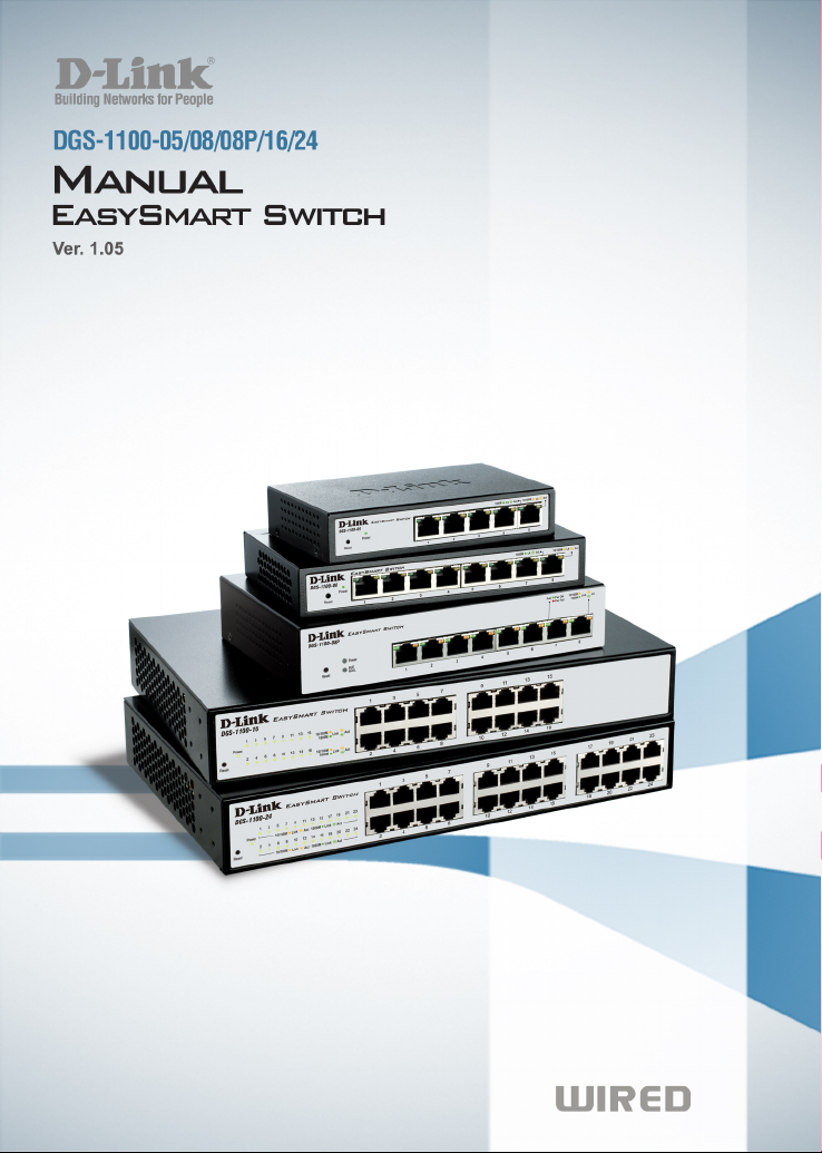
Figure 1– DGS-1100-05 Front Panel
Power LED: The Power LED lights up when the Switch is connected to a power source.
Link/Act/Speed LED (Ports 1-5):
Flashing: Indicates a network link through the correspond ing port.
Blinking: Indicates that the Switch is either sending or receiving data to the port.
Green: Indicates that the port is running at 1000M.
Amber: Indicates that the port is running at 10/100M.
Light off: No link.
Reset: By pressing the Reset button for 5 seconds the Switch will change back to the default configuration
and all changes will be lost.
Rear Panel
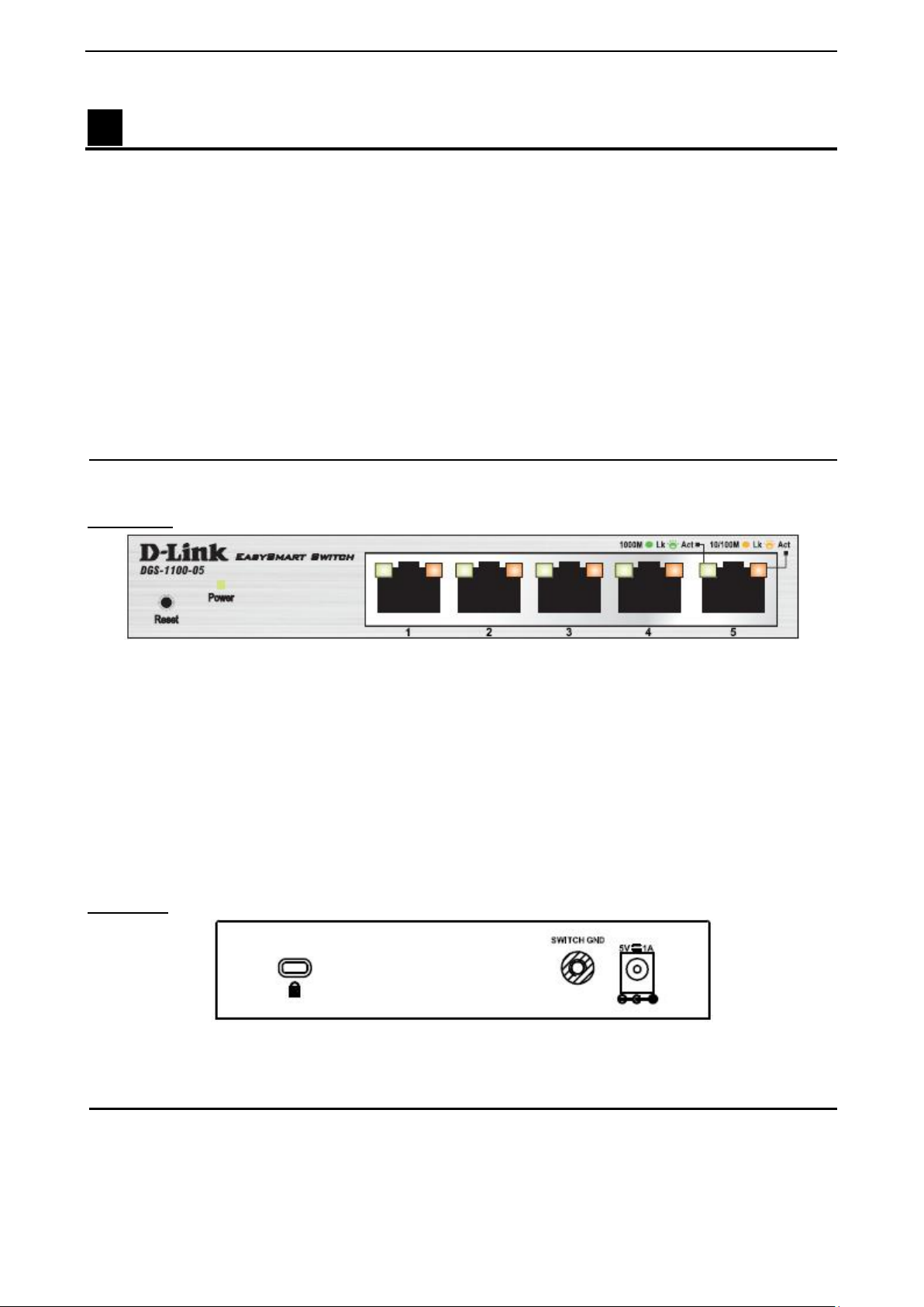
Figure 2– DGS-1100-05 Rear Panel
5V/1A AC adapter: The port is where to connect the 5V/1A AC adapter.
DGS-1100-08
8-Port 10/100/1000Mpbs EasySmart Switch.
2
Page 8
D-Link EasySmart Switch User Manual
Front Panel
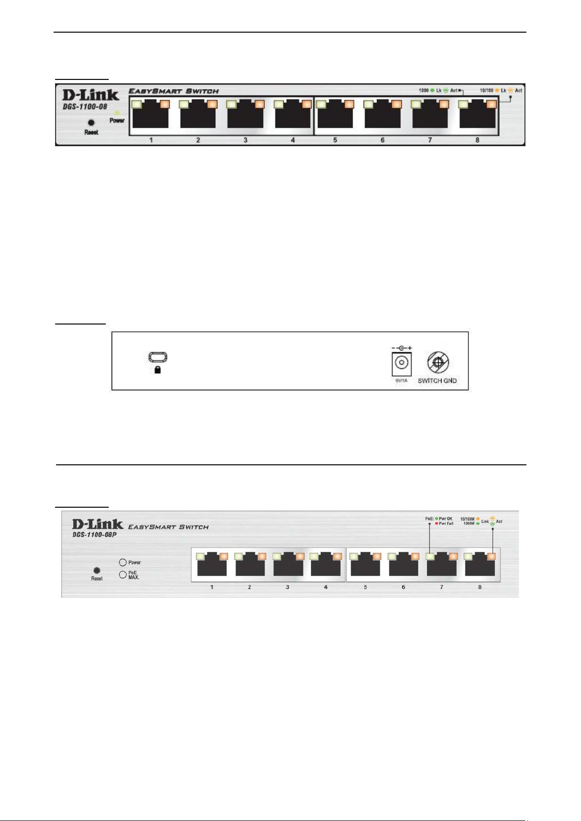
Figure 3 – DGS-1100-08 Front Panel
Power LED: The Power LED lights up when the Switch is connected to a power source.
Link/Act/Speed LED (Ports 1-8):
Flashing: Indicates a network link through the corresponding port.
Blinking: Indicates that the Switch is either sending or receiving data to the port.
Green: Indicates that the port is running at 1000M.
Amber: Indicates that the port is running at 10/100M.
Light off: No link.
Reset: By pressing the Reset button for 5 seconds the Switch will change back to the default configuration
and all changes will be lost.
Rear Panel
Figure 4 – DGS-1100-08 Rear Panel
5V/1A AC adapter: The port is where to connect the 5 V/1A AC adapter.
DGS-1100-08P
8-Port 10/100/1000Mpbs PoE EasySmart Switch.
Front Panel
Figure 5 – DGS-1100-08P Front Panel
Power LED: The Power LED lights up when the Switch is connected to a power source.
PoE MAX. LED:
Light up: Indicates the pow er output to PDs is over 57W. No additiona l PDs can be powered for
safety consideration.
Blinking: Indicates if the u s er unplugg ed c er ta in PDs and made the PoE power budget left over 7W,
the PoE MAX LED will blink 2 minutes.
Light off: Indicates the power budget is using less than 57W.
Link/Act/Speed LED (Ports 1-8):
Flashing: Indicates a network link through the corresponding port.
Blinking: Indicates that the Switch is either sending or receiving data to the port.
33
Page 9
D-Link EasySmart Switch User Manual
Green: Indicates that the port is running at 1000M.
Amber: Indicates that the port is running at 10/100M.
Light off: No link.
PoE LED (Ports 1-8):
Green: Indicates the PoE powered device (PD) is connected and the port supplies power
successfully.
Red: The PoE port has failed, possibly due to:
1. PoE total power budget shortage
2. Over current: Exceeds the power current of powered device's classification.
3. Short circuit: Short circuit has been performed on a powered device
Light off: Indicates no Powered Device (PD) connected.
Reset: By pressing the Res et button for 5 seconds th e Switch will change back to the default configuration
and all changes will be lost.
Rear Panel
Figure 6 – DGS-1100-08P Rear Panel
48V/1.57A Desktop adapter: The port is where to connect the 48V/1.57A Desktop adapter.
DGS-1100-16
16-Port 10/100/1000Mpbs EasySmart Switch.
Front Panel
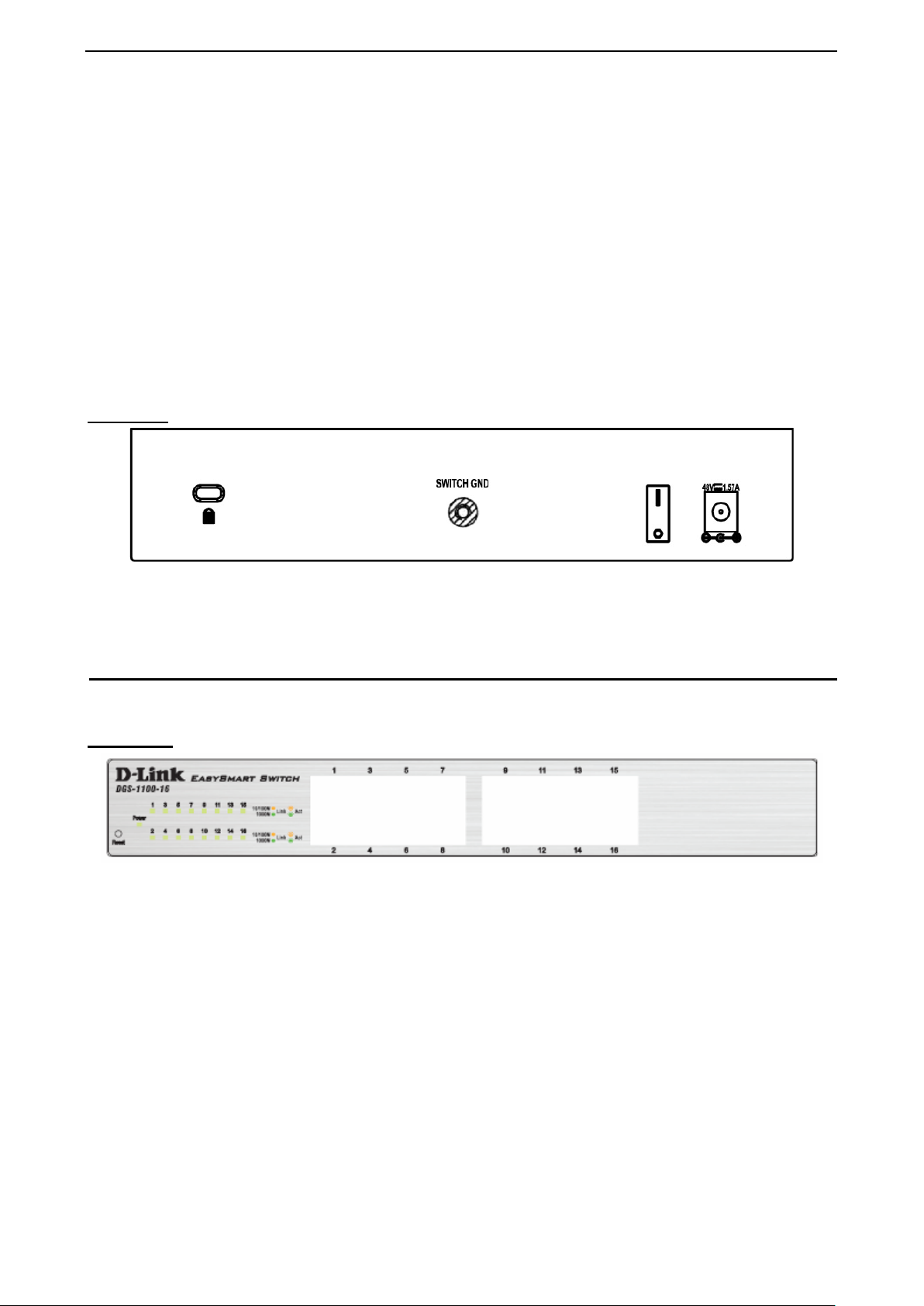
Figure 7 - DGS-1100-16 Fron t P anel
Power LED: The Power LED lights up when the Switch is connected to a power source.
Link/Act/Speed LED (Ports 1-16):
Flashing: Indicates a network link through the corresponding port.
Blinking: Indicates that the Switch is either sending or receiving data to the port.
Green: Indicates that the port is running at 1000M.
Amber: Indicates that the port is running at 10/100M.
Light off: No link.
Reset: By pressing the Res et button for 5 seconds th e Switch will change back to the default configurat ion
and all changes will be lost.
4
Page 10
D-Link EasySmart Switch User Manual
Rear Panel
Figure 8 – DGS-1100-16 Rear Panel
Power: The power port is where to connect the AC power cord.
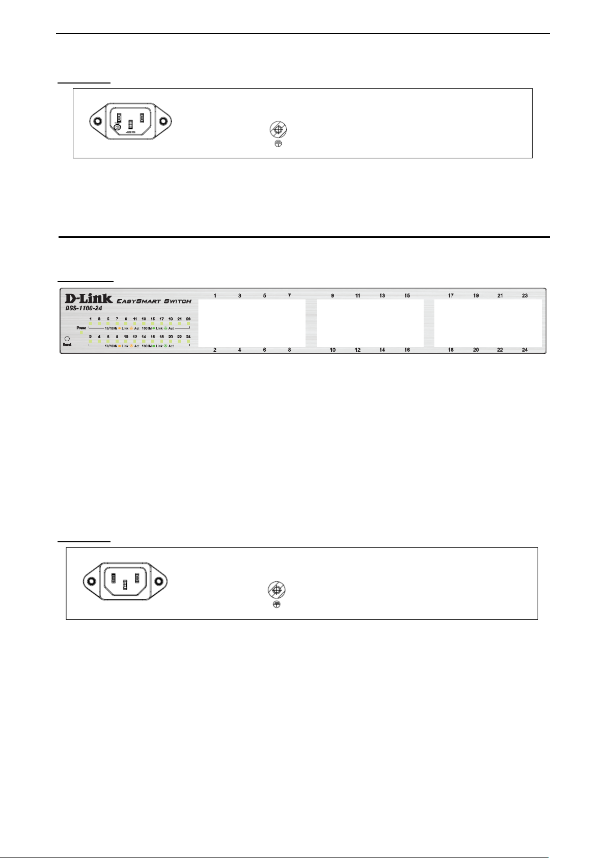
DGS-1100-24
24-Port 10/100/1000Mpbs EasySmart Switch.
Front Panel
Figure 9 – DGS-1100-24 Front P anel
Power LED: The Power LED lights up when the Switch is connected to a power source.
Link/Act/Speed LED (Ports 1-24):
Flashing: Indicates a network link through the corresponding port.
Blinking: Indicates that the Switch is either sending or receiving data to the port.
Green: Indicates that the port is running at 1000M.
Amber: Indicates that the port is running at 10/100M.
Light off: No link.
Reset: Press the reset but ton for 5 seconds to res et the Switch back to the default set tings. All previous
changes will be lost.
Rear Panel
Figure 10– DGS-1100-24 Rear Pan e l
Power: Connect the supplied AC power cable to this port.
55
Page 11

D-Link EasySmart Switch User Manual
2 Hardware Installat io n
This chapter provides unpacking and installation information for the D-Link EasySmart Switch.
Step 1: Unpacking
Open the shipping carton and carefully unpack its contents. Please c onsult the packing list located in the
User Manual to mak e sure all i tems are present and u ndamaged. If an y item is missing or dam aged, pleas e
contact your local D-Link reseller for replacement.
Packing contents of DGS-1100-05/08
One D-Link EasySmart Switch
One AC Power Adapter
Four rubber feet
One accessory kit for wall-mount installation
One ground screw that screw on the D-Link EasySmart Switch
One Multi-lingual Getting Started Guide
One CD with User Manual and SmartConsole Ut ility program
Packing contents of DGS-1100-08P
One D-Link EasySmart Switch
One Desktop Power Adapter
One AC power cord
Four rubber feet
One ground screw that screw on the D-Link EasySmart Switch
One Multi-lingual Getting Started Guide
One CD with User Manual and SmartConsole Ut ility program
Packing contents of DGS-1100-16/24
One D-Link EasySmart Switch
One AC power cord
Four rubber feet
Screws and two mounting brackets
One accessory kit for a ground screw
One Multi-lingual Getting Started Guide
One CD with User Manual and SmartConsole Ut ility program
If any item is found missing or damaged, please contact the local reseller for replacement.
Step 2: Switch Installation
For safe switch installation and operation, it is recommended that you:
Visually inspect the power cord to see that it is secured fully to the AC power connector.
Make sure that there is proper heat dissipation and adequate ventilation around the switch.
Do not place heavy objects on the switch.
Desktop or Shelf Installation
When installing the switc h on a desktop or shelf, the r ubber feet included w ith the device must be attac hed
on the bottom at each c orner of the device’s base. A llow enough ventilation s pace between the dev ice and
the objects around it.
6
Page 12
D-Link EasySmart Switch User Manual
Figure 11 – Attach the adhesive rubber pads to the bottom
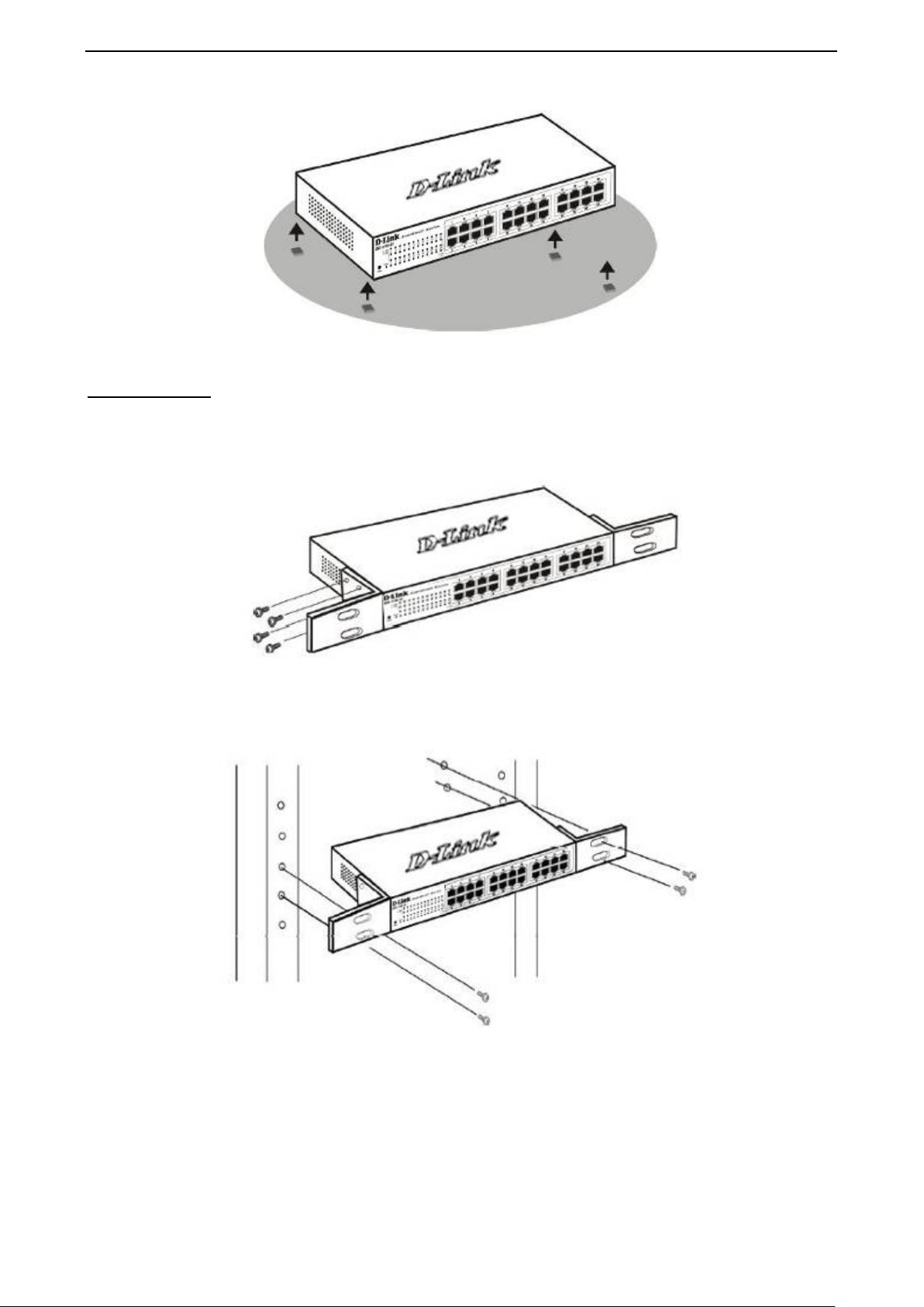
Rack Installation
The switch can be mounted in an EIA standard size 11-inch r ac k , which c a n be p lac ed i n a wir ing closet with
other equipment. T o install, attac h the m ounting br ackets to th e switc h’s side p anels (one on each s ide) and
secure them with the screws provided (please note that these brackets are not designed for palm size
switches).
Figure 12 – Attach the mounting brackets to the Switch
Then, use the screws provided with the equipment rack to mount the switch in the rack.
Figure 13– Mount the Switch in the rack or chassis
Please be aware of following safety Instructions when installing:
A) Elevated Operat ing Ambient - If instal led in a closed or multi-u nit rack assembly, the op erating ambient
temperature of the rac k environm ent ma y be greater than room ambient. T herefor e, considera tion should b e
given to installing the equipment in an environm ent c ompatible with the maximum ambient temperature (Tma)
specified by the manufacturer.
77
Page 13
D-Link EasySmart Switch User Manual
B) Reduced Air Flow - Installation of the e quipment in a rack should be such that the amount of air flow
required for safe operation of the equipment is not compromised.
C) Mechanical Loading - Mounting of the equipm ent in the r ack s hould be such th at a hazar dous c onditio n is
not achieved due to uneven mechanical loading.
D) Circuit Overloading - Consideration should be given to the connection of the equipment to the supply
circuit and the eff ect that over loading of t he circuits m ight hav e on overcur rent protecti on and suppl y wiring.
Appropriate consideration of equipment nameplate ratings should be used when addressing this concern.
E) Reliable Earthing - Reliable earthing of rack-mounted equipment should be maintained. Particular
attention should be give n to supply connecti ons other than direct c onnections to the branch c ircuit (e.g. use
of power strips)."
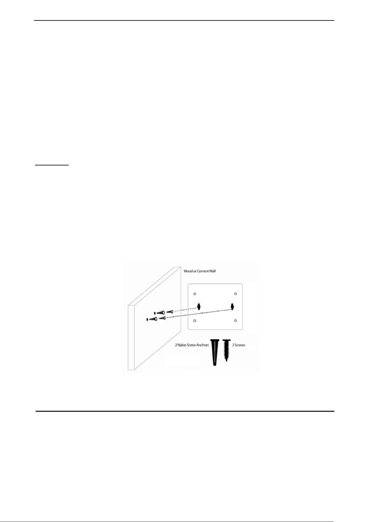
Wall-mount
The Switch can be mounted o n a wall. T wo mounting slots are pr ovided on the bottom of the switc h for this
purpose.
Please follow the installation steps to complete wall-mount process.
Mounting on a cement wall
Step 1: Mount the nylon screw anchors ø5 x 22L mm (included in the accessory kit ) into a cement wall
Step 2: Drive the T3 x 15L screws into the nylon screw anchors.
Step 3: Hook the mounting holes of the switch back on the screws.
Mounting on a wood wall
Step 1: Drive the T3 x 15L screws into a wood wall.
Step 2. Hook the mounting holes of the switch back on the screws.
Figure 14 –Wall mount installation
Step 3 – Plugging in the AC Power Cord
Users may now connect th e AC power cord into the r ear of the switch and to an electrical outlet (pref erably
one that is grounded and surge protected).
8
Page 14
D-Link EasySmart Switch User Manual
Figure 15 –Plugging the switch into an outlet
Power Failure
As a precaution, th e switch s hould be u nplugged in cas e of power f ailure. W hen po wer is resum ed, plug t he
switch back in.
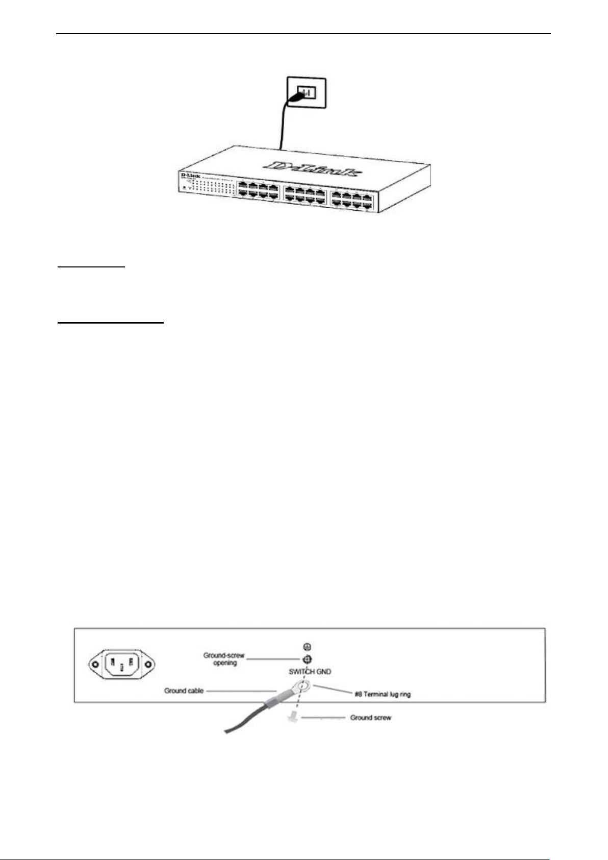
Grounding the Switch
This section describes ho w to connect the EasySmart Switch to ground. You m ust complete this procedure
before powering your switch.
Required Tools and Equipment
Ground screws (included in the accessory kit): One M4 x 6 mm (metric) pan-head sc rew
Ground cable (not included in the accessory kit): T he grounding cable sho uld be sized according to
local and national installation requirements. Depending on the power supply and system, a 12 to 6
AWG copper conductor is required for U.S installation. Commercially available 6 AWG wire is
recommended. The length of the cable depends on the proximity of the switch to proper grounding
facilities.
A screwdriver (not included in the accessory kit)
The following steps let you connect the switch to a protective ground:
Step 1: Verify if the system power is off.
Step 2: Use the ground cable to place the #8 term inal lug ring on top of the ground-screw opening, as seen
in the figure below.
Step 3: Insert the ground screw into the ground-screw opening.
Step 4: Using a screwdriver, tighten the ground screw to secure the ground cable to the switch.
Step 5: Attach the terminal lug r ing at the ot her end of the gr oundin g cable to an appropr iate ground ing stud
or bolt on rack where the switch is installed.
Step 6: Verify if the connections at the ground connector on the switch and the rack are securely attached.
Figure 16 –Ground cable, screw and #8 terminal lug rings
99
Page 15

D-Link EasySmart Switch User Manual
3 Getting Started
This chapter introduces the management interface of D-Link EasySmart Switch.
Management Options
The D-Link EasySmart Switch can be managed through an y port on the device by using the W eb-based
Management or through any PC using the SmartConsole Utility.
Each switch must be assigned its own IP Address, which is used for communication with Web-Based
Management. The PC’s IP address should be in the sam e range as the switch. Each s witch can allow only
one user to access the Web-Based Management at a time.
The PC should ha ve an IP address in the sam e range as the switch. Each switc h can allow one user to
access to the Web-Based Management at a time.
However, if you want to m anage multiple D-Link EasySmar t Switches, the SmartConsole Utility is a m ore
convenient choice. B y using the Smar tConsole Ut ility, you do not ne ed to cha nge the IP address of your PC
and it is easier to initialize multiple EasySmart Switches.
Please refer to the f ollowing i nstallation instructions f or the W eb-based Managem ent and th e SmartCons ole
Utility.
Using Web-based Management
After a successf ul ph ysica l ins ta lla tio n, you can configure the Switch, monitor the network status , an d d is play
statistics using a web browser.
Supported Web Browsers
The embedded Web-based Management currently supports the following web browsers:
Internet Explorer 6/7 or later version
Netscape 8 or later versi on
Mozilla
Firefox 1.5/2.0 or later vers ion
Chrome 5.0 or later version
Safari 4.0 or later version
Connecting to the Switch
You will need the following equipment to begin the web configuration of your device:
1. A PC with a RJ-45 Ethernet connection
2. A standard Ethernet cable
Connect the Ethernet cable to any of the ports on the front panel of the switch and to the Ethernet port on the
PC.
10
Page 16

D-Link EasySmart Switch User Manual
Figure 17 –Connected Et hernet cable
Login Web-based Management
In order to login and config ure the s witch vi a an Ether net connection, the PC m ust have a n IP addres s in t he
same subnet as the s witc h. For example, if the switch has an IP address of 10.90.90.90, the PC should have
an IP address of 10.x.y.z (where x/y is a num ber betw een 0 ~ 254 and z is a number bet ween 1 ~ 254), and
a subnet mask of 255.0.0.0. There are two ways to launch the Web-based Management, you may either click
the Web Access button at the top of the SmartConsole Utility or open the web browser and enter 10.90.90.90
(the factory-default IP address) in the address bar. Then press <Enter>.
Figure 18 –Enter the IP address 10.90.90.90 in the web browse r
NOTE: T he switch's f actor y default IP addres s is
10.90.90.90 with a subne t m ask of 255.0.0 .0 and
a default gateway of 0.0.0.0.
The web configuration can also be accessed through the SmartConsole Utility. Open the SmartConsole
Utility and double-click the switch as it appears in the Monitor List. This will automatically load the web
configuration in your web browser.
When the following logo n dialog box appears, enter the password then click OK. The default password is
admin.
Figure 19 – Logon Dialog Box
SmartConsole Utility
The SmartConsole Utili ty included in t he installation C D is a program for discovering D-Link Smart Switches
and EasySmart Switches within the same L2 net work segment connected to your PC. T his tool is only for
computers running Windows 2000, Windows XP, Windows Vista x64/32 or Windows 7 x64/32 operating
1111
Page 17

D-Link EasySmart Switch User Manual
SmartConsole Utility from your PC before
systems. There are two op tions for the installation of the SmartConsol e Utility; one is through the autorun
program on the installation CD and the other is manual installation.
NOTE: Please be sure to uninstall any existing
installing the latest SmartConsole Utility.
Option 1: Follow these steps to install the SmartConsole Utilit y via the autorun program on the ins tallation
CD.
1. Insert the Utility CD into your CD-Rom/DVD-Rom Drive.
2. The autorun program will appear automatically.
3. Click on the ”Install Sm artConsole Utility” butt on and an installation wi zard will guide you through the
process.
4. After successfully installing the SmartConsole Utility, you can open the utility by clicking Start >
Programs > D-Link SmartConsole Utility.
5. Connect the Smart Switch to the same L2 network segment of your PC and use the SmartConsole
Utility to discover the Smart Switches.
Option 2: Follow these steps to install the SmartConsole Utility manually.
1. Insert the Utility CD into your CD-Rom/DVD-Rom Drive.
2. From the Start menu on the Windows desktop, click Computer.
3. Double click on you CD-Rom/DVD-Rom Drive to start the a utorun menu, or right click on the Drive to
open the folder. Select SmartConsole Utility and double click on the .exe file.
4. Follow the on-screen instructions to install the utility.
5. Upon completion, go to Start > Program s > D-Link SmartConsole Ut ility and open the SmartCons ole
Utility.
6. Connect the Smart Switch to the same L2 network segment of your PC and use the SmartConsole
Utility to discover the Smart Switches.
For detailed explanations of SmartConsole’s functions, please refer to Chapter 4 SmartConsole Utility
12
Page 18

D-Link EasySmart Switch User Manual
4 SmartConsole Utility
The D-Link SmartConsole Utility allows the administr ator to quickly discover al l D-Link Smart Switches and
EasySmart Switches which are in the same dom ain of the PC, collect tra ps and log messages, and q uick
access to basic configurations of the switch.
The SmartConsole Utility consists of thr e e parts , Device Configurations at the top, Device L ist as the main
body, and SmartConsole Settings at the left.
Figure 20– SmartConsole Utility
SmartConsole Settings
The SmartConsole Settings at the left has five icons, Utility Settings, Log, Trap, File, and Help.
Utility Settings
Click this icon to launch the Utility Settings window. Refresh time refreshes the d ev ic es w hich wer e s elect ed
as monitored device in the Device List. Choices include 15 s ecs, 30 secs, 1mins, 2mins, and 5 mins for
selecting the monitoring tim e intervals. Utility Group Interval establishes the inter vals (in seconds) that the
Switch will be discovered in the Smar tCons ole De vice List.
Figure 21– SmartConsole Utility Settings
NOTE: If the Group Interval is set to 0, IGMP
Snooping must be disabled in the Switch or the
switches will not be discovered.
1133
Page 19

D-Link EasySmart Switch User Manual
Log
Click this icon t o launc h the Log window. Click Vi ew Log to show the events of the Sm ar tConsole Utilit y and
the device. Date/Time indicates when the message was received, IP denotes where it comes from and
Status shows the content of this log message. Click Clear Log to clear all log entries. Click OK to exit.
Figure 22– SmartConsole Log
Trap
Click this icon to launch the Trap w indow. Click View Trap to sho w the events of the SmartConsole Utility
and the device. Date/Time indicates when the trap message was recei ved, IP denotes w here it comes from
and Status shows the content of this trap message. Click Clear Trap to clear all entries. Click OK to exit
Figure 53 – SmartConsole Trap
The trap icon in the SmartConsole Settings will change while receiving new trap messages. Please see
below for detailed description.
Icon Description
No new traps
New traps was received
Monitor List
By clicking on this icon you will see below options:
14
Page 20

D-Link EasySmart Switch User Manual
Figure 24– SmartConsole Monitor List
Monitor Save: Records the setting of the Device List as default for th e next tim e the SmartConsole Utility is
used.
Monitor Save As: Records the setting of the Device List in an appointed filename and file path.
Monitor Load: Manually load a Device List setting file.
About
Click this icon to launch the SmartConsole Info window.
Figure 25– SmartConsole About
Device Configuration
The Device Configuration in the SmartConsole Utility has five icons:
Device Settings
Password Manager
Firmware Upgrade
DHCP Refresh
Web Access
And the
Select a switch f rom the Dev ice List. Click o n this ic on to lau nch t he Device Settings wi ndow. Here you can
configure the Product Name, IP Address , Gateway, Subnet Mask, System Name, Loc ation, Trap Host IP,
and DHCP Client Setti ng of the Switc h.
To apply the configurat ion, insert the correct device password in the Confirm Password box and the n click
OK
, device buttons for the Device List.
Device Settings
1155
Page 21

D-Link EasySmart Switch User Manual
. Therefore, ensure to
Figure 26 – SmartConsole Device Settings
NOTE: The EasySmart Switch automatically
sends out discovery packets to maintain the
connection between the devices and
SmartConsole Utility
configure the Group Interval setting.
Password Manager
Select a switch from the Device List. Click on this icon to launch the Device Password Manager window.
Here you can enter a new password and confirm it.
Figure 27– Smart C on s o le P assword Manager
Firmware Upgrade
Select one or many switches of same model name from the Device List. Click on this icon to launch the
Firmware Upgrade window. Specify the Firmware Pat h (or Browse f or one) that you are going to use. Input
the correct password of device, and then click Upgrade. The state will show "OK" after completion, and “Fail”
is firmware upgrade fails or cannot be completed for any reason.
16
Page 22

D-Link EasySmart Switch User Manual
Figure 28 –Firmware Upgrade
DHCP Refresh:
If a DHCP-client enabled s witch in the Device List shows the default IP is still used, it means the device did
not receive an IP address from the DHCP server successfully. Select that switch and c lick the DHC P ref res h
icon. Enter the correct D evice Password and then click OK. The device will renew the I P address from the
DHCP server.
Figure 29 – DHCP Refresh
Web Access
Select a switch from the Device List. Click this icon to launch your internet browser (e.g. The Internet
Explorer). Here you can co nfigure the S witch through the W eb-based Mana gement utility. You may also get
into the Web-based Management by double-clicking the device in the device list.
Add (+), Delete (-) and Discover the device
Click the Discovery button to display all the Web Smart and EasySmart switches located in the same
domain with the management PC.
Click the + and insert a device IP address to add a dev ice into Discover List, or select a device and click
the – button to remove it.
Figure 30 – SmartConsole Add device
1177
Page 23

D-Link EasySmart Switch User Manual
Figure 31 – SmartConsole Delete devic
Device List
This list displays all discovered Web Smart and EasySmart switches on the network.
e
Figure 32– SmartCons o le Dev ice List
Definitions of the Device List features:
Monitor: The
the device keep updating t he information, The icon will become
reachable, the icon will change to
in the monitor means the dev ice was discovered b y SmartConsole. Click the icon to have
. When the device was detected as not
. Please check if the power or the cable of this device is disconnected.
Product Name: Displays the device product name.
IP Address: Displays the current IP addresses of devices.
Subnet Mask: Displays the Subnet Mask setting of the device.
Gateway: Displays the Gateway setting of the device.
MAC Address: Displays the device MAC Addresses.
Firmware version: Displays the current Firmware version of this device.
System Name: Displays the appointed device system name.
Location: Displays where t he appointed device location.
SNMP: Displays the SNMP status of the device. This is not available for EasySmart switches.
Trap IP: Displays the IP address of host where the Trap information will be sent to.
DHCP: Specify if the device gets the IP address from a DHCP server.
Group Interval: Displays the intervals (in seconds). This feature is not available for EasySmart switches.
NOTE: If the devices are marked r ed in the d evice
list, it means that the devices require upgrading
firmware again.
18
Page 24

D-Link EasySmart Switch User Manual
If you close the web browser without
5 Configuration
The features and functions of the D-Link EasySmart Switch can be c onfigured for optim um use throug h the
Web-based Management Utility.
Web-based Management
After a successful login you will see the screen below:
Figure 33 – Web-based Management
Above is the Web-based M anagem ent screen. T he three main ar eas are the Tool Bar on top, the Function
Tree, and the Main Configuration Screen.
The Tool Bar provides a quick and convenient way for essential utility functions like firmware and
configuration management.
By choosing different functions in the Function Tree, you can change all the settings in the Main
Configuration Screen. The main configuration s cr ee n wil l show the current stat us of your Switch by click ing
the model name on top of the function tree.
At the upper right corner of the screen the username and current IP address will be displayed.
Under the username is the Logout button. Click this to end this session.
NOTE:
clicking the Logout button, it will be seen as an
abnormal exit and the login session will still be
occupied.
Finally, b y clic k ing on the D-Link logo at the upper-left corner of the screen you will be redirected to th e local
D-Link website.
1199
Page 25

D-Link EasySmart Switch User Manual
Tool Bar > Save Menu
The Save Menu provides Save Configuration.
Figure 34 – Save Menu
Save Configuration
Select to save the entire configuration changes you have made to the device to switch’s non-volatile RAM.
Figure 35– Save Configuration
Tool Bar > Tool Menu
The Tool Menu offers global function controls such as R eset Syst em, Reboot Device, Firmware Upgrade and
Configuration Backup & Restore.
Figure 36 – Tool Menu
Reboot Device Provide a safe way to reboot the system. Click Reboot to restart the switch.
Figure 37– Tool Menu > Reboot Devi ce
Reset System
Provide a safe reset option for the Switch. All configuration settings in non-volatile RAM will be reset to
factory default and then the Switch will reboot.
Figure 38– Tool Menu > Reset System
Firmware Backup & Upgrade
Click Backup to save the firmware to your disk.
Click Browse to browse your inventories for a saved firmware file.
Click Upgrade after selecting the firmware file you want to restore.
20
Page 26

D-Link EasySmart Switch User Manual
Figure 39 – Tool Menu > Firmware backup & upgrade
CAUTION: Do n ot disconnect the PC or remove
the power cord from device until upgrade is
complete. The Switch may crash if the Firmware
Upgrade is incomplete.
Configuration Backup & Restore
Allow the current conf iguration se ttings to be s aved to a f ile, and if neces sary, you c an restore configuration
settings from the file.
Figure 40– Tool Menu > Configure Backup and Restore
Select backup the current settings to file include password or exclude password.
Backup or restore the configuration file to or from your local drive.
Click Backup to save the current settings to your disk.
Click Choose File to browse your inventories for a saved backup settings file.
Click Restore after selecting the backup settings file you want to restore.
Note: Switch will reboot aft er restore and
all current configurations will be lost.
2211
Page 27

D-Link EasySmart Switch User Manual
Function Tree
All configuration opt ions on the switc h are accessed through the Setup menu on the left s ide of the scr een.
Click on the setup item that you want to configure. The following s ections provid e more detailed description
of each feature and function.
Figure 41–Function Tree
Device Information
The Device Information provi des an overview of the switch which includes essential inform ation such as
firmware, hardware and IP address.
It also offers an overall status of common software features:
Port Mirroring: Click L2 Features > Port Mirroring. By default this feature is disabled.
Storm Control: Click QoS > Storm Control. By default this feature is disabled.
IGMP Snooping: Click L2 Features > IGMP Snooping. By default this feature is disabled.
Port Trunking: Click L2 Features > Trunking Setting. By default this feature is disabled.
802.1Q VLAN: Click VLAN > 802.1Q VLAN. By default this feature is enabled.
Loopback Detection: Click L2 Features > Loopback Detection. By default this feature is disabled.
22
Page 28

D-Link EasySmart Switch User Manual
Figure 42– Device Information
System > System Settings
The System Setting allows the user to configure the IP address and the basic system information of the
Switch.
Figure 43 – System > System Setting
IP Information: There are two wa ys for the s witch to obtain an IP address: Static and DHCP (Dynamic Host
Configuration Protocol).
When using static m ode, the IP Address , Subnet Mask, Gateway and DHCP retry Time can be m anually
configured. W hen using DHCP mode, the Switch will f irst look for a DHCP server to provide it with an IP
address (including network mask and default gateway) before using the default or previously entered settings.
By default the IP setting is static mode with IP addr ess is 10.90.90.90 and s ubnet mask is 255.0.0.0. For
DGS-1100-16/24, the DHCP retry Time is not supported.
System Information: By entering a System Name and System Location, the device can m ore easily be
recognized through the SmartConsole Utility and from other EasySmart devices on the LAN.
Login Timeout: The Login Timeout contr ols the idle time-out period f or secur ity purposes, when there is no
action for a specif ic tim e sp an in the Web-bas ed Man agem ent. If th e curren t ses sion t im es out (ex pires), the
user is required a re-login before using the Web-based Mana gement again. Selective range is from 3 to 30
minutes, and the default setting is 5 minutes.
2233
Page 29

D-Link EasySmart Switch User Manual
Be sure to adjust port speed settings
appropriately after changing connected cable
System > Port Settings
In the Port Setting page, the status of all ports c an be m onitored an d adjusted f or optim um conf iguration. B y
selecting a range of por ts ( Fro m Port and To Port), the Speed can be set for all selecte d ports, ef fec tive by
clicking Apply. Press the Refresh button to view the latest information.
Figure 44 – System > Port Setting
Speed: Copper connection s can operate in Forced M ode settings (1000M F ull, 100M Full, 100M Half , 10M
Full, 10M Half), Auto, or Disabled. The default setting for all ports is Auto.
NOTE:
media types.
Link Status: Reporting Down indicates the port is disconnected.
Flow Control: You can enable this func tion to m itigat e the traff ic c ongestion. P orts configur ed for f ull-duplex
use 802.3x flow control, half-duplex ports use backpressure flow control. The default setting is disabled.
System > Trap Settings
By configuring the Trap Set ting, it allo ws SmartCons ole Utilit y to monitor spec ified events on this EasySmart
Switch. By default, Trap Setting is disabled. W hen the Trap Setting is enabled, enter the Destination IP
address of the managing station that will receive trap information.
Figure 45 - Sys tem > Trap Settings
Select the event message(s) to be sent out to the managing station.
System Event: The system level messages contain:
Device Bootup - System boot-up information.
Illegal Login - Events of incorrect password logins and records the IP of the source PC.
Twisted pair Port Link Up/Link Down: Copper port connection information.
Firmware Upgrade State: Information of firmware upgrade - success or failure.
System > 802.1az EEE Set t ing s The 802.1az EEE Settings page allows user to enable or disable the 802.1az EEE feature of the Switch.
Figure 46 - Sys tem > 802.1az EEE Setting
24
Page 30

D-Link EasySmart Switch User Manual
NOTE: The DGS-1100-16/24 does not support to
enable or disable 802.1az EEE function.
System > Password Access Control
Setting a password is a critical tool for managers to secure the EasySmart Switch. After enter ing the old
password and the new password two times, click Apply for the changes to take effect.
Figure 47 – System > Password Access Control
L2 Features > Jumbo Frame
Jumbo Frame suppor t is designed to enhance Ethern et networking throughput and sig nificantly reduce the
CPU utilization of larg e file transfers lik e large multimedia f iles or large data fil es by enabling more eff icient
larger payloads per pac ket. The Jum bo Frame page allows network m anagers to enable Jum bo Frames on
the device.
The Jumbo Frame default is disabled, Select Enabled then click Apply to turn on the jumbo frame support.
Figure 48 – System > Jumbo Frame
NOTE: DGS-1100-05/08/08P Supports Jumbo Frame
function, but DGS-1100-16/24 will not support it.
L2 Features > Port Trunking
The Trunking function allows the switch to combine t wo or four ports together to increase bandwidth. Select
the Trunking Groups, choose the Members to be grouped together, and then click Apply to activate the
selected Trunking Groups. Up to 4 Trunking Groups may be created, each supporting up to four ports.
Disable - Removes all the members in this trunk group.
Figure 49- L2 Features > Port Trunking Settings
L2 Features > IGMP Snooping
With Internet Group Management Protocol (IGMP) snooping, the EasySmart Switch can make intelligent
multicast forwarding decisions by examining the contents of each frame’s Layer 2 MAC header.
By default, IGMP is disa b le d . If enabled, the EasySmart switch can recognize IGMP qu er ies a nd r eports s e nt
between network stations or devices and an IGMP host. With IGMP snooping enabled, the EasySmart switch
will forward multicast traffic only to the connections that have members attached.
2255
Page 31

D-Link EasySmart Switch User Manual
not support
Figure 50 – L2 Features > IGMP Snoo ping setting
L2 Features > Multicast Entry Table (DGS-1100-08 only)
The Multicast Entry Table page displays the multicast entry information list.
Figure 52 – L2 Features > Multicast Entry Table
L2 Features > Apple Talk
The Apple Talk page allows user to enable or disable the Apple Talk function.
Figure 53 – L2 Features > Apple Talk
NOTE: The DGS-1100-16/24 does
Apple Talk function.
L2 Features > Port Mirroring
Port Mirroring is a method of monitoring network traffic that forwards a copy of each incoming and/or
outgoing packet fr om one port of the Switch to anoth er port where the packet c an be studied. This enable s
network managers to better monitor network performances.
Figure 54 – L2 Features > Port Mirroring
Target Port: Specifies the port to be mirrored.
Selection Sniffer Mode for the Source Ports is as follows:
TX (transmit) mode: Duplicates the data tr ans mitted from the sourc e por t a nd forwards it to t he T arget Port.
Click “all” to include all ports into port mirroring.
RX (receive) mode: Duplicates the data that received from the source port and forwards it to the Target Port.
Click “all” to include all ports into port mirroring.
Both (transmit and receive) mode: Duplicate bo th the data transmitted f rom and data sent to the s ource
port, and forwards all the data to the assigned Target Port. Click “all” to include all ports into port mirroring.
NOTE: T he tar get p orts w ill s top mirroring packets
if there are unknown tags or destination packets
sent out by source ports.
26
Page 32

D-Link EasySmart Switch User Manual
L2 Features > Loopback Detection
The Loopback Detec tion function is used to detec t the loop created by a spec ific port while Spanning Tr ee
Protocol (STP) is not enabled in the network, especially when the down links are hubs or unmanaged
switches. T he Switch will automatically shut dow n the port. The Loopbac k Detection port will be unlock ed
when the Loopback Detection Recover Time times out. The Loopback Detection function can be
implemented on a range of ports at a time.
Figure 55– L2 Features > Loopback Detection
Loopback Detection: Enable or disable Loopback detection. The default is Disabled.
Interval (1-32767): Set a Loop detection Interval between 1 and 32767 seconds. The default is 1 seconds.
Recover Time (0 or 60-1000000): Time allowed (in seconds) for recovery when a Loopback is detected.
The Loop Detection Recover Time can be set at 0 seconds, or 60 to 1000000 seconds. Entering 0 will
disable the Loop Detection Recover Time. The default is 60 seconds.
From Port: The beginning of a consecutive group of ports may be configured starting with the selected port.
To Port: The ending of a consecutive group of ports may be configured starting with the selected port.
State: Use the drop-down menu to toggle between Enabled and Disabled. Default is Disabled.
Click Apply to implement changes made.
L2 Features > Statistics
The Statistics screen displays the status of each port packet count.
Figure 56– L2 Features > Statistics menu
Refresh All: Renews the details collected and displayed.
Clear All Counters: To reset the details displayed.
TxOK: Number of packets transmitted successfully.
RxOK: Number of packets received successfully.
TxError: Number of transmitted packets resulting in error.
RxError: Number of received packets resulting in error.
2277
Page 33

D-Link EasySmart Switch User Manual
•
•
•
•
L2 Features > Cable Diagnostics
The Cable Diagnostics is designed primarily for administrators and customer service representatives to
examine of the copper cable quality. It rapidly determines the type of cable errors occurred in the cable.
Select a port and then click the Test Now button to start the diagnosis.
Figure 57 – L2 Features > Cable Diagnostics
Test Result: The description of the cable diagnostic results.
OK means the cable is good for the connection.
Short in Cable means the wires of the RJ45 cable may be in contact somewhere.
Open in Cable means the wires of RJ45 cabl e may be broken or the other end of the c able is simply
disconnected.
Test Failed m eans som e other errors occur red during c able diagnos tic s. Pleas e sel ect t he s am e port a nd
test again.
Cable Fault Distance (meters): Indicates the d istanc e of the ca ble f ault f rom the Switch por t, if the c able i s
less than 2 meters, it will show “No Cable”. The deviation of "Cable Fault Distance" is +/-2 meters.
NOTE: Cable length detect ion is effective at ever y
speed of 10Mbps, 100Mbps and 1Gbps.
VLAN > 802.1Q VLAN
A VLAN is a group of ports that can be anywher e in the network, but communicate as thoug h they were in
the same area.
VLANs can be eas ily or gan ized to ref lect department groups (such as R&D, M arketin g), us age gr oups ( such
as e-mail), or multicast groups (multimedia applicatio ns such as video conferencing), an d therefore help to
simplify network management by allowing users to move devices to a new VLAN without having to change
any physical connections.
By defau lt, 80 2.1Q VL AN is disabled. With 802.1Q VL AN ena ble d, the V LAN VID 1 is created b y default wit h
an empty VLAN name field and all ports are configured as “Untagged” members.
The 802.1Q VLAN configuration is accomplished in three steps:
Enabling 802.1Q VLAN function
Creating a new VID group and assigning ports as Untagged, Tagged or Not Member.
Configuring the PVID of access VLAN
Add VID: Click to create a new VID group, assigning ports from 1 to 8 as Untagged, Tagged, or Not
Member. VLAN VID is a unique number (between 1 and 4094) that identifies a particular VLAN. A port ca n
be untagged in only one VID. To save the VID group, click Apply. You can also change the nam e according
to the desired groups.
PVID settings: Port VLAN ID (PVID) is an identification that encompasses a particular switch port’s
identification and VLAN membership. This identification is used to classify the incoming untagged frames.
Click to configure the PVID of a port.
28
Page 34

D-Link EasySmart Switch User Manual
Figure 58 – VLAN > 802.1Q VLAN > Default Setting
Add VID: Click to create a new VID group, assigning ports from 1 to 8 as Untagged, Tagged, or Not
Member. VLAN VID is a unique number (between 1 and 4094) that identifies a particular VLAN. A port can
be untagged in only one VID. To save the VID group, click Apply. You can also change the name according
to the desired groups.
Figure 59 – VLAN > 802.1Q VLAN > Add VID
Figure 60 – VLAN > 802.1Q VLAN > Assign PVID
Rename: Click to rename the VLAN group.
Delete VID: Click to delete the VLAN group.
Figure 61 – VLAN > 802.1Q VLAN > VID Configuration
NOTE: When 802.1Q VLAN is enabled, th e PortBased VLAN settings will be set to Disabled.
VLAN > 802.1Q Management VLAN
802.1Q VLAN is used to decide which VLAN can access the switch.
2299
Page 35

D-Link EasySmart Switch User Manual
VLAN is
Figure 62 – VLAN > 802.1Q Management VLAN
NOTE: When 802.1Q Management
enabled, the 802.1Q VLAN should be enabled
first.
VLAN > Port-Base VLAN
Port-Based VLANs are the simplest and m ost com mon form of VLAN. It assigns the appliance LAN ports t o
VLANs, effec tively transforming the appliances. You can as sign multiple ports to the sam e VLAN, or each
port to a separate VLAN. The default is disabled.
Figure 63 – VLAN > Port-Based VLAN Settings
Select the Enabled radio to enable the Port-Based VLAN function.
Figure 64 – VLAN > Port-Based VLAN Enabled
Figure 65 – VLAN > Port-Based VLAN – Add VLAN
Add V LAN: Click to create a new VLAN nam e and to selec t VLAN ports. The VLAN name should be less
than 10 characters. To save the members in a group, click Apply.
Rename: Click to rename the VLAN group.
Delete VID: Click to delete the VLAN group.
NOTE: When Port-Based VLAN is enabled, the
802.1Q VLAN settings and 802.1Q management
VLAN settings will be set to Disabled as default.
By default, all ports are untagged.
30
Page 36

D-Link EasySmart Switch User Manual
VLAN > Surveillance VLAN
Surveillance VLAN is a feature that allows you to automatically place the video traffic from D-Link IP cameras
to an assigned VLAN to e nhance the IP surveillance service. With a higher pri ority and individual VLAN,
the quality and the s ecurity of surve illance traff ic are guaranteed. T he Surveillance VL AN function
will check the source MAC addres s / VLAN ID on the incom ing pack ets . If it matc hes specif ied MAC
address / VLAN ID, the packets will pass through switch with desired priority.
3
VViiddeeoo MMaannaaggeemmeenntt SSooffttwwaarree ++ SSttoorraaggee
VViiddeeoo MMaannaaggeemmeenntt SSooffttwwaarre
1
The Surveillance VLAN settings are accomplished in the following steps.
1. Enable Surveillanc e VL AN
2. Select a VLAN ID to become a surveillance VLAN and set the priority (By default, the priority is high)
3. D-Link Camer as can be rec ognized a nd pl aced into the VL AN d ynam icall y. For oth er br ands of cam er a or
storages/servers, manual settings are required in “User-Defined MAC Settings” with a maximum entry
number of 2:
Component Type: Surveillance VLAN will automatically detect D-Link Surveillance Devices by default.
There are another five surveillance components that could be options to be configured for surveillance
VLAN. These five components are Video Management Server (VMS), VMS Client, Video Encoder,
Network Storage, and Other IP brand’s Surveillance Devices. Usually, VMS and VMS Clients are
necessary components for an IP surveillance service.
Description: Enter description for a component.
MAC address: Enter MAC address of component.
1
e
EEaassyySSmmaarrtt SSwwiittcchh
2
Figure 66 – L2 Features > Surveillance VLAN Settings
3311
Page 37

D-Link EasySmart Switch User Manual
Figure 67 – L2 Features > Surveillance VLAN Settings > Component type
VLAN > Voice VLAN
Voice VLAN is a feature that allo ws you to automaticall y place the voice traffic from D-Link IP phones to an
assigned VLAN to enhanc e the IP voice servic e. With a higher pr iority and individual VLAN, the quality
and the security of voice traf fic are guaranteed. The Voice VLAN function will check the source MAC
address / VLAN ID on the incoming packets. If it matches specified MAC address / VLAN ID, the packets will
pass through switch with desired priority.
Figure 68 – L2 Features > Voice VLAN Settings
VLAN > Traffic Segmentation
Traffic segmentation is used to limit traffic flow for a group of ports on a single Switch. This method of
segmenting the flow of traf fic is similar to using VLANs to limit traff ic, but is more restrictive. To conf igure
traffic segmentatio n, specify several por ts as protecte d ports, the res t as unprote cted ports. Pr otected ports
or unprotected ports will be allowed to forward packets to other unprotec ted ports , however, pro tected ports
will be forbidden to forward packets to other protected ports.
By default, the Traffic Segmentation is disabled.
Figure 69 – VLAN > Traffic Segmentation
NOTE: DGS-1100-16/24 do not support Traffic Segmentation
function.
QoS > 802.1p Default Priority
QoS is an implementation of the IEEE 802.1p standard that allows network administrators to reserve
bandwidth for impor tant f unc tions th at r equ ire a larger bandwidth or that might ha ve a hi gher pr iority, such as
VoIP (voice-over Internet Protocol), web browsing applications, file server applications or video conferencing.
Thus with larger bandwidth, less critical traffic is limited, and therefore excessive bandwidth can be saved.
32
Page 38

D-Link EasySmart Switch User Manual
The following figure dis p lays the status of Quality of Service priority levels of eac h port, higher priority means
the traffic from this port will be first handled by the switch. For packets that are unt agged, the switch will
assign the priority depending on your configuration.
Figure 70 – QoS > 802.1p Default Priority
Queuing Mechanism: Select Strict Priorit y to process the packets with t he hig hes t priorit y first. Selec t W RR
(Weighted Round-Robin) to process packets according to the weigh t of each priority. W hen a priority level
has reached its egress weight, the system will process the packets in the next level even if there are
remaining packets . D-Link EasySmart Switc h system’s weight of priority levels are: 8 (H ighest), 4 (High), 2
(Medium) and 1 (Low) packet. By default, the queuing mechanism is Strict Priority.
For DGS-1100-08, it also supports DSCP Default Priorit y Setti ngs:
Figure 71 – QoS > 802.1p Default Priority
Select QoS Mode: Select 802.1p or DSCP mode to be specified.
QoS > Storm Control
The Storm Control feature provides the ability to control the receive rate of broadcast, multicast, and
unknown unicast pack ets. Once a pack et storm has been detecte d, the Switc h will drop p acket s coming into
the Switch until the storm has subsided.
Figure 72 – QoS > Storm Control
3333
Page 39

D-Link EasySmart Switch User Manual
24 support 128 Static MAC
Storm Control Type: User can select the different St orm type from Broadcast Onl y, Multicast & Broadc ast,
and Multicast & Broadcast & Unknown Unicas t.
Threshold (pps): If storm control is enabled (by default it is disab led), the threshold can be set from 1 to
1,000,000pps.
Click Apply for the settings to take effect.
QoS > Bandwidth Control
The Bandwidth Contr ol pag e allo ws net work manager s to d efine the ba ndwidt h se ttings for a s pecif ied por t’s
transmitting and receiving data rates.
Figure 73 – QoS > Bandwidth Control
From Port / To Port: A consecutive group of ports may be configured starting with the selected port.
Type: This drop-down m enu al lo ws you to select between RX (receive), TX ( transmit), and Both. T his setting
will determine whether the bandwidth ceiling is applied to receiving, transmitting, or both receiving and
transmitting packets.
No Limit: This drop-down menu allows you to specify that the selected port will have no bandwidth limit.
Enabled disables the limit.
Rate: This drop-down menu allows you to select data rate from 64Kbps to 512Mbps.
Click Apply to set the bandwidth control for the selected ports.
Security > MAC Address Table > Static MAC
This feature provides two distinct functions. The Disable Auto Learning Excluding Uplink Port table allows
turning off the f unction of learning MAC address auto matically, if a p ort isn't specified as an uplink port ( for
example, connects to a DHCP Server or Gateway). By default, this feature is Off (disabled).
Figure 74 – Security > Static Mac Address
NOTE: DGS-1100-16/
Address entries, but DGS-1100-05/08/08P only
support 32 entries.
To initiate the rem oval of auto-learning f or any of the uplink ports, click On to enable th is feature, and then
select the port(s) for auto learning to be disabled.
The Static MAC Address Setting table dis plays the static MAC ad dresses connected, as well as the VID.
Click Add Mac to add a new MAC address, you also need to select the assigned Port number, enter both the
34
Page 40

D-Link EasySmart Switch User Manual
Mac Address and VID and Click Apply. Clic k Delete to remove one entry or click Delete all to clear the lis t.
You can also copy a learn ed MAC address from Dynamic Forwarding Table (please refer to Security >
MAC Address Table > Dynamic Forwarding Table for details).
By disabling Auto Learning capabil ity and specify the static MAC addresses, the network is protec ted from
potential threats like hackers because traffic from illegal MAC addresses will not be forwarded by the Switch.
Security > MAC Address Table > Dynamic Forwarding Table
For each port, this table displays the MAC addr ess learned by the S witch. To add a MAC address to the
Static Mac Address List, cli ck the Add c h ec kbox, and then click Apply associated with the identified address.
Figure 75 – Security >Dynamic Forwarding Table
PoE > PoE Global Settings (DGS-1100-08P only)
This page allows user to conf igur e the g lo bal Po E setti ngs of the dev ice and a ls o displ a ys cur rent PoE s tat us
including Total PoE Power Budget, Power Used, Power Left and The percentage of system power supplied.
Figure 76 – PoE > PoE Global Settings
System Power Threshold (PoE Power Threshold): Manually configure the PoE power budget 7.1 ~ 64.0
watts.
System Setting Disc onnect Met hod (Power Shut Off Sequence): Defines the method used to den y power to
a port once the threshold is reached. The possible fields are:
Deny next port: When the power budget is exceeded, the next por t attempting to power up is denied,
regardless of the port priority.
Deny low priority port: The port with the lower priority will be shut down to allow the higher priority
port to power up.
Click Apply to make the configurations take effects.
System Power Status: Displays the system power status of device.
System Budget Power (Total PoE Power Budget): Displays the total PoE power budget of this switch.
Support Total Power (Power Used): Displays the current used PoE power.
Remainder Power (Power Left): Displays the left PoE power.
The ratio of system power supply (The percentage of PoE pow er supplied): Displa ys the per c en tag e
of PoE power supplied.
3355
Page 41

D-Link EasySmart Switch User Manual
Power Voltage, and Current is the power usage
For the PoE Port Settings table, if the
PoE > PoE Port Settings (DGS-1100-08P only)
DGS-1100-08P supports Po wer over Ethern et (PoE) as defined b y the IEEE s pecificatio n. It supplies power
to PD device up to 15.4W for all ports, meeting IEEE802.3af standards.
DGS-1100-08P works with all D-Link 802.3af devices. The Switch also works in PoE mode with all non-
802.3af capable D-Link AP, IP Cam and IP phone equipment via the PoE splitter DWL-P50.
DGS-1100-08P reserves 7 Watts for guard band in order to ensure the connection of the lowest priority PD.
The maximum power used by power devices is define d by the following classification
Class Usage Output power limit by PSE
0 Default 15.4W
1 Optional 4.0W
2 Optional 7.0W
3 Optional 15.4W
The PoE port table will disp lay the PoE status including, Port State, Priority, Power Limit, Power (W ) , Voltag e
(V), Current (m A), C lass if icatio n, Sta tus . You c an s ele ct F r om Port / To Port to cont rol the P oE f unc tio ns of a
port. DGS-1100-08P will auto disable the ports if port current is over 375mA in 802.3af mode.
NOTE: The PoE Status inf ormation of Power current,
information of the con nected PD; please "Refresh" to
renew the information.
Figure 77 – PoE > PoE Port Setting
From Port/To Port: Specifies the PoE function of a port or ports.
State: Select “Enabled” or “Disabled” to configure PoE function for designated port(s). Default is Enabled.
Priority: C onfigure the po wer supply priorit y as “Low”, “Norm al”, or “High” on designated port( s). Default is
Normal.
Power Limit: This function allows you to manually set the port power current limitation to be given to the PD.
To protect the DGS-1100-08P and the connecte d devices, the power limit func tion will disable the PoE
function of the port when the po wer is overloaded. Selec t from "Class 1", "Class 2", "Class 3" and "Auto"
for the power limit. "Auto" wil l negotiate and follow the c lassification from the PD po wer current based on
the 802.3at standard.
User Define: Check the box and input the power budget (fr om 1.0 to 15.4W) to manuall y assign an upper
limit of port power budget on designated port(s).
Click Apply to make the configurations take effects or click Refresh to redisplay the table.
NOTE:
classification was shown as “Legacy PD”, it will
be classified to non-AF PD or Legacy PD.
36
Page 42

D-Link EasySmart Switch User Manual
Appendix A - Ethernet Technology
This chapter will describe the features of the D-Link EasySmart Switch and provide some background
information about Ethernet/Fast Ethernet/Gigabit Ethernet switching technology.
Gigabit Ethernet Technology
Gigabit Ethernet is an extension of IEEE 802.3 Ethernet utilizing the same packet structure, format, and
support for CSMA/CD protocol, full duplex, and management objects, but with a tenfold increase in
theoretical throughput of over 100-Mbps Fast Eth ernet and a hundredfold inc rease over 10-Mbps Etherne t.
Since it is compatible with all 10-Mbps and 100-Mbps Ethernet en vironments, Gigabit Ethernet provides a
straightforward upgrade wit hout was ti ng existing investments in hardware, software, or trained personnel.
The increased spe ed and extra bandwidth off ered by Gigabit Ethernet is es sential to help solving network
bottlenecks that f requently develop as more advance d computer users and ne wer applications continue to
demand greater network resourc es. Upgr ading k ey com ponents , such as backbone connections and server s
to Gigabit Ethernet techn ology c an great l y improve netw ork respons e tim es as well as signif icant ly sp eed up
the traffic between subnets.
Gigabit Ethernet ena bles fast optica l fiber connec tions to supp ort video confer encing, com plex imaging, and
similar data-intensive applications. Likewise, since data transfer s occur 10 times faster than Fast E thernet,
servers outfitted with Gigabit Ethernet NIC’s ar e able to perform 10 tim es the number of operations in the
same amount of time.
In addition, the phenom enal bandwidth delivered by Gigabit Ethernet is the most cost-effective m ethod to
take advantage of today and tomorrow’s rapidly improving switching and routing internetworking
technologies. And with expected advances in the coming years in silicon technology and digital signal
processing that will enabl e Gigab it Eth ernet to event u a ll y operat e over uns hi elded tw isted-pair (UTP) cabling,
outfitting your net work with a powerful 1000-Mbps-capable backbone/ser ver connection which wi ll create a
flexible foundation for the next generation of network technology products.
Fast Ethernet Technology
The growing importance of LANs and the increasing complexity of desktop computing applications are
fueling the need for high performance networks. A number of high-speed LAN technologies have been
proposed to provid e gr eate r ban d width a nd improve client/server res p ons e times. Among them, 100 B AS E -T
(Fast Ethernet) provides a non-disruptive, smooth evolution from the current 10BASE-T technology. The
non-disruptive and sm ooth evolution natur e, and the dom inating potential m arket base, virtuall y guarantees
cost-effective and high performance Fast Ethernet solutions.
100Mbps Fast Ethernet is a standard specifie d by the IEEE 802.3 L AN committee. It is an ex tension of the
10Mbps Ethernet sta ndard with the ability to trans mit and receive data at 100 Mbps, while maintaining the
CSMA/CD Ethernet protoc ol. S ince the 1 00Mbps Fast Etherne t is com patible wit h all ot her 10Mbps Eth ernet
environments, it pro vides a straightf orward upgrade a nd utilizes exist ing investments in har dware, software,
and personnel training.
Switching Technology
Another approach to push beyond the limits of Ethernet technology is the development of switching
technology. A switch bridges Ethernet packets at the MAC address leve l of the Et h er net protocol transmitting
among connected Ethernet or Fast Ethernet LAN segments.
Switching is a cost-effective wa y of increasing the tot al network capacity avai lable to users on a loca l area
network. A switch increases capacity and decre ases network loading by d ividing a local area net work into
different segments which won’t compete with each other for network transmission capacity.
The switch acts as a high-speed selective bridge between the individual segments. The switch, without
interfering with any other segments, automatically forwards traffic that needs to go from one segment to
another. By doing this the total network capacity is multiplied, while still maintaining the same network
cabling and adapter cards.
3377
Page 43

Appendix B - Technical Specifications
D-Link EasySmart Switch User Manual
Hardware Specifications
Key Components / Performance
Switching Capacity:
- DGS-1100-05 :10Gbps
- DGS-1100-08/08P: 16Gbps
- DGS-1100-16: 32Gbps
- DGS-1100-24: 48Gbps
Max. Forwarding Rate:
- DGS-1100-05: 7.4 Mbps
- DGS-1100-08/08P: 11.9Mbps
- DGS-1100-16: 23.8Mbps
- DGS-1100-24: 35.7Mbps
Forwarding Mode: Store and Forward
Packet Buffer memory:
- DGS-1100-05: 1.0 Mbits
- DGS-1100-08/08P: 2.0 Mbits
- DGS-1100-16: 3.5 Mbits
- DGS-1100-24: 3.5 Mbits
Flash Memory: 2M Bytes
Port Functions
5/8/16/24 10/100/1000BaseTX ports
compliant with the following standards:
- IEEE 802.3
- IEEE 802.3u
- IEEE 802.3ab
- IEEE 802.3af(DGS-1100-08P only)
-Supports Full/half-Duplex operations at
10/100Mbps
-Supports Full-Duplex operation at
1000Mbps
-Supports IEEE 802.3x Flow Control
-Support Auto-Negotiation
-Compliant to IEEE 802.3az Energy
Efficiency Ethernet.
Physical & Environment
DGS-1100-05/08: External 5V/1A AC
Power Adapter
DGS-1100-08P: External 48V/1.57A
Desktop Power Adapter
DGS-1100-16/24: AC input, 100~240
VAC, 50/60Hz, internal universal power
supply
Acoustic Value:
- DGS-1100-05/08/08P/16/24: 0dB (Fanless)
Operation Temperature:
- DGS-1100-05/08/16/24: 0~40°C
- DGS-1100-08P:Device: 0~50°C
Power Adapter: 0~40°C
Storage Temperature -10~70°C
Operation Humidity: 10%~95% RH
Storage Humidity: 5%~95% RH
Emission (EMI) Certifications
FCC class A
CE Class A
VCCI Class A
BSMI Class A(DGS-1100-08P only)
Safety Certifications
CUL, LVD, CE, BSMI(DGS-1100-08P
only)
Features
L2 Features
Supports up to 8K MAC address
IGMP snooping
Loopback Detection
Port Mirroring
Port Trunking
Cable Diagnostics
VLAN
802.1Q VLAN standard (VLAN Tagging)
802.1Q Management VLAN
Port-Based VLAN
Surveillance VLAN
Voice VLAN:
QoS (Quality of Service)
802.1p priority,
Up to 4 queues per port
Bandwidth Control
Storm Control
Management
Web-based GUI or SmartConsole Utility
Configuration backup / restoration via
Web-based management
Firmware backup & upgrade via Web-
based management
Reset, Reboot system
Factory reset by pressing reset button
Power Saving
IEEE 802.3az Compliant (Energy Eff icient
Ethernet)
D-Link Green Technologies
- Power saving by cable length
- Power saving by link status
38
Page 44

D-Link EasySmart Switch User Manual
Appendix C – Rack mount Instructions
Safety Instructions - Rack Mount Instructions - The following or similar rack-mount instructions are included
with the installation instructions :
A) Elevated Operating Ambient - If installed in a closed or multi-unit rack assembly, the operating ambient
temperature of the rack environment may be greater than room ambient. Therefore, consideration should be
given to installing the equ ip ment in an environment compatible with the maximum ambient temperature (Tm a)
specified by the manufacturer.
B) Reduced Air Flow - Installation of the equipment in a rack should be such that the amount of air flow
required for safe operation of the equipment is not compromised.
C) Mechanical Loading - Mounting of the equipment in the rack should be such that a hazardous condition is
not achieved due to uneven mechanical loading.
D) Circuit Overloading - Consideration should be given to the connection of the equipment to the supply
circuit and the effect that overloading of the circuits might have on overcurrent protection and supply wiring.
Appropriate consideration of equipment nameplate ratings should be used when addressing this concern.
E) Reliable Earthing - Reliable earthing of rack-mounted equipment should be maintained. Particular
attention should be given to supply connections other than direct connections to the branch circuit (e.g. use
of power strips).
39
Page 45

Page 46

 Loading...