

Page 1

D-Link ™ DES-3250TG
Stackable Layer 2 Switch
User’s Guide
____________________
Page 2

D-Link DES-3250TG Standalone Layer 2 Switch
Information in this document is subject to change without notice.
© 2005 D-Link Computer Corporation. All rights reserved.
Reproduction in any manner whatsoever without the written permission of D-Link Computer Corporation is strictly forbidden.
Trademarks used in this text: D-Link and the D-Link logo are trademarks of D-Link Computer Corporation; Microsoft and Windows are registered trademarks
of Microsoft Corporation.
Other trademarks and trade names may be used in this document to refer to either the entities claiming the marks and names or their products. D-Link
Computer Corporation disclaims any proprietary interest in trademarks and trade names other than its own.
March 2005 P/N 651TG3250055
ii
Page 3

D-Link DES-3250TG Standalone Layer 2 Switch
Table of Contents
Preface ..............................................................................................................................................vii
Intended Readers...............................................................................................................................vii
Notes, Notices, and Cautions ..........................................................................................................vii
Safety Instructions .........................................................................................................................viii
Protecting Against Electrostatic Discharge ....................................................................................... x
Introduction .......................................................................................................................................... 1
Fast Ethernet Technology ................................................................................................................... 1
Gigabit Ethernet Technology ............................................................................................................... 1
Switch Stacking.................................................................................................................................. 1
Features ............................................................................................................................................. 2
Ports................................................................................................................................................... 2
Traffic Classification and Prioritization ............................................................................................... 3
Management....................................................................................................................................... 3
Unpacking and Setup............................................................................................................................ 4
Unpacking .......................................................................................................................................... 4
Installation ......................................................................................................................................... 4
Desktop or Shelf Installation ............................................................................................................ 4
Rack Installation .............................................................................................................................. 5
Power on............................................................................................................................................. 6
Power Failure ................................................................................................................................... 6
Identifying External Components .......................................................................................................... 7
Front Panel......................................................................................................................................... 7
Rear Panel .......................................................................................................................................... 7
Side Panels ......................................................................................................................................... 8
Gigabit Combo Ports ........................................................................................................................... 8
LED Indicators ................................................................................................................................... 8
Connecting the Switch ........................................................................................................................ 10
Switch to End Node .......................................................................................................................... 10
Switch to Hub or Switch ................................................................................................................... 10
10BASE-T Device ........................................................................................................................... 11
100BASE-TX Device....................................................................................................................... 11
Stacking vs. Standalone Operation ................................................................................................... 11
Managing Switch Stacks................................................................................................................... 12
Changes to Switch Stack Structure ................................................................................................ 13
Convert a Standalone Switch to a Stacked Switch .......................................................................... 13
Add a Switch to a Stack ................................................................................................................. 14
Swap a Master from a Stack........................................................................................................... 15
Stacking with DGS-3312SR ........................................................................................................... 16
Introduction to Switch Management.................................................................................................... 17
Management Options........................................................................................................................ 17
Web-based Management Interface .................................................................................................... 17
SNMP-Based Management................................................................................................................ 17
Command Line Console Interface Through the Serial Port ................................................................ 17
Connecting the Console Port (RS-232 DCE).................................................................................... 18
First Time Connecting to The Switch ................................................................................................ 19
Password Protection ......................................................................................................................... 20
SNMP Settings .................................................................................................................................. 21
Traps ............................................................................................................................................. 22
iii
Page 4

D-Link DES-3250TG Standalone Layer 2 Switch
MIBs .............................................................................................................................................. 22
IP Address Assignment ..................................................................................................................... 22
Connecting Devices to the Switch ..................................................................................................... 24
Web-based Switch Management .......................................................................................................... 25
Introduction ..................................................................................................................................... 25
Login to Web Manager ...................................................................................................................... 25
User Accounts Management ............................................................................................................. 26
Admin and User Privileges.............................................................................................................. 26
Save Changes ................................................................................................................................... 27
Areas of the User Interface................................................................................................................ 28
Web Pages ........................................................................................................................................ 29
Configuration ...................................................................................................................................... 30
IP Address ........................................................................................................................................ 31
Switch Information ........................................................................................................................... 33
Advanced Settings ............................................................................................................................ 33
Serial Port Settings ........................................................................................................................... 35
MAC Notification............................................................................................................................... 35
Port Configuration ............................................................................................................................ 36
Port Description................................................................................................................................ 38
Port Mirroring ................................................................................................................................... 39
Stack Setting .................................................................................................................................... 41
Static ARP Settings ........................................................................................................................... 42
IGMP ................................................................................................................................................ 43
IGMP Snooping .............................................................................................................................. 43
Static Router Ports Entry ............................................................................................................... 45
Spanning Tree .................................................................................................................................. 46
STP Switch Settings ....................................................................................................................... 48
STP Port Settings ........................................................................................................................... 50
Forwarding Filtering ......................................................................................................................... 53
Unicast Forwarding........................................................................................................................ 53
Multicast Forwarding ..................................................................................................................... 53
VLANs .............................................................................................................................................. 55
Static VLAN Entry .......................................................................................................................... 57
Port VLAN ID(PVID) ........................................................................................................................ 60
Port Bandwidth ................................................................................................................................ 63
SNTP Settings ................................................................................................................................... 65
Current Time Settings .................................................................................................................... 65
Time Zone and DST........................................................................................................................ 66
Port Security..................................................................................................................................... 66
Port Security Settings..................................................................................................................... 67
Port Security Clear ......................................................................................................................... 68
QOS (Quality of Service).................................................................................................................... 70
Traffic Control ................................................................................................................................ 70
802.1p Default Priority................................................................................................................... 72
802.1p User Priority ....................................................................................................................... 74
(QOS Output) Scheduling............................................................................................................... 74
Traffic Segmentation ...................................................................................................................... 75
LACP ................................................................................................................................................ 76
Link Aggregation ............................................................................................................................ 76
LACP Port ...................................................................................................................................... 79
Configuring the Access Profile Table ................................................................................................. 80
System Log Hosts ............................................................................................................................. 97
Port Access Entity (802.1X)............................................................................................................... 97
802.1x Port-Based and MAC-Based Access Control........................................................................ 97
Authentication Server .................................................................................................................... 98
iv
Page 5

D-Link DES-3250TG Standalone Layer 2 Switch
Authenticator ................................................................................................................................. 99
Client ........................................................................................................................................... 100
Authentication Process................................................................................................................. 101
Understanding 802.1x Port-based and MAC-based Network Access Control................................. 101
Port-Based Network Access Control ............................................................................................. 102
MAC-Based Network Access Control ............................................................................................ 103
Configure Authenticator ............................................................................................................... 103
Port Capability Settings................................................................................................................ 106
Initialize Port(s) for Port Based 802.1x.......................................................................................... 108
Initializing Ports for MAC Based 802.1x ....................................................................................... 109
Reauthenticate Port(s) for Port Based 802.1x ............................................................................... 109
Reauthenticate Port(s) for MAC-based 802.1x .............................................................................. 110
RADIUS Server............................................................................................................................. 110
Management ..................................................................................................................................... 112
Security IP ...................................................................................................................................... 112
User Accounts ................................................................................................................................ 112
SNMPV3 ......................................................................................................................................... 113
SNMP User Table ......................................................................................................................... 113
SNMP View Table ......................................................................................................................... 115
SNMP Group Table....................................................................................................................... 117
SNMP Community Table .............................................................................................................. 119
SNMP Host Table ......................................................................................................................... 120
SNMP Engine ID .......................................................................................................................... 121
Monitoring ........................................................................................................................................ 122
CPU Utilization ............................................................................................................................... 122
Port Utilization................................................................................................................................ 123
Packets........................................................................................................................................... 125
Received (RX) ............................................................................................................................... 125
UMB-cast (RX) ............................................................................................................................. 127
Transmitted (TX) .......................................................................................................................... 129
Errors............................................................................................................................................. 131
Received (RX) ............................................................................................................................... 131
Transmitted (TX) .......................................................................................................................... 133
Size ................................................................................................................................................ 135
Packet Size................................................................................................................................... 135
MAC Address .................................................................................................................................. 137
ARP Table ....................................................................................................................................... 139
IGMP Snooping Group .................................................................................................................... 140
IGMP Snooping Forwarding ............................................................................................................ 141
VLAN Status ................................................................................................................................... 142
Router Port ..................................................................................................................................... 143
Port Access Control ........................................................................................................................ 143
Authenticator Status.................................................................................................................... 143
Maintenance ..................................................................................................................................... 145
TFTP Utilities .................................................................................................................................. 145
Download Firmware from Server .................................................................................................. 145
Download Settings from TFTP Server............................................................................................ 146
Upload Settings to TFTP Server .................................................................................................... 146
Upload Log to TFTP Server ........................................................................................................... 146
Switch History ................................................................................................................................ 147
Ping Test......................................................................................................................................... 147
Save Changes ................................................................................................................................. 148
Reboot Services .............................................................................................................................. 148
Reboot ......................................................................................................................................... 149
v
Page 6

D-Link DES-3250TG Standalone Layer 2 Switch
Reset............................................................................................................................................ 149
Reset System ............................................................................................................................... 149
Reset Config ................................................................................................................................. 150
Logout.......................................................................................................................................... 150
Appendix A ....................................................................................................................................... 150
Technical Specifications.................................................................................................................. 150
Appendix B ....................................................................................................................................... 153
Understanding and Troubleshooting the Spanning Tree Protocol .................................................... 153
Warranty and Registration ................................................................................................................ 162
vi
Page 7

D-Link DES-3250TG Standalone Layer 2 Switch
Preface
The DES-3250TG Manual is divided into sections that describe the system installation and operating instructions with
examples.
Section 1, Introduction - Describes the Switch and its features.
Section 2, Unpacking and Setup- Helps you get started with the basic installation of the Switch and also describes the front
panel, rear panel, side panels, and LED indicators of the Switch.
Section 3, Identifying External Components - Tells how you can connect the Switch to your Ethernet network.
Section 4,
Ethernet/Gigabit Ethernet network.
Section 5, Switch Management and Operating Concepts - This chapter discusses many of the concepts and features used to
manage the switch, as well as the concepts necessary for the user to understand the functioning of the switch.
Section 6, Web-Based Switch Management - Introduces basic Switch management features, including password protection,
SNMP settings, IP address assignment and connecting devices to the Switch.
Section 7, Configuration - A detailed discussion about configuring some of the basic functions of the Switch, including
accessing the Switch information, using the Switch's utilities and setting up network configurations, such as Quality of
Service, The Access Profile Table, port mirroring and configuring the Spanning Tree.
Section 8, Management – A detailed discussion regarding the Simple Network Monitoring Protocol including description of
features and a brief introduction to SNMP.
Section 9, Monitoring - Features graphs and screens used in monitoring features and packets on the Switch.
Section 10, Maintenance - Features information on Switch utility functions, including TFTP Services, Switch History, Ping
Test, Save Changes and Rebooting Services.
Appendix A, Technical Specifications - The technical specifications of the Switch.
Appendix B, Understanding and Troubleshooting Spanning Tree Protocol -
Connecting The Switch - This chapter describes how to connect the DES-3250TG to your Ethernet/Fast
Intended Readers
The DES-3250 User’s Guide contains information for setup and management and of the DES-3250TG switch. This guide is
intended for network managers familiar with network management concepts and terminology.
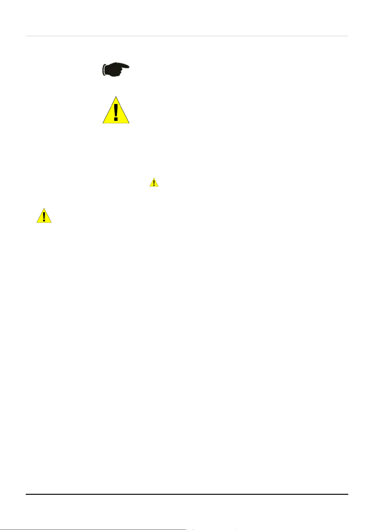
Notes, Notices, and Cautions
NOTE: A NOTE indicates important information that helps you make
better use of your device.
vii
Page 8
D-Link DES-3250TG Standalone Layer 2 Switch
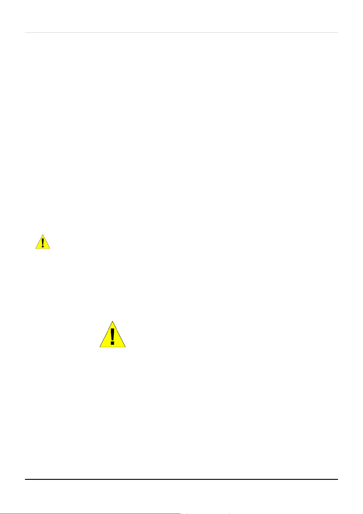
NOTICE: A NOTICE indicates either potential damage to hardware or loss
of data and tells you how to avoid the problem.
CAUTION: A CAUTION indicates a potential for property damage,
personal injury, or death.
Safety Instructions
Use the following safety guidelines to ensure your own personal safety and to help protect your system from potential damage.
Throughout this safety section, the caution icon ( ) is used to indicate cautions and precautions that you need to review and
follow.
Safety Cautions
To reduce the risk of bodily injury, electrical shock, fire, and damage to the equipment, observe the following precautions.
Observe and follow service markings. Do not service any product except as explained in your system documentation. Opening
or removing covers that are marked with the triangular symbol with a lightning bolt may expose you to electrical shock. Only
a trained service technician should service components inside these compartments.
If any of the following conditions occur, unplug the product from the electrical outlet and replace the part or contact your
trained service provider:
– The power cable, extension cable, or plug is damaged.
– An object has fallen into the product.
– The product has been exposed to water.
– The product has been dropped or damaged.
– The product does not operate correctly when you follow the operating instructions.
• Keep your system away from radiators and heat sources. Also, do not block cooling vents.
• Do not spill food or liquids on your system components, and never operate the product in a wet environment. If the
system gets wet, see the appropriate section in your troubleshooting guide or contact your trained service provider.
• Do not push any objects into the openings of your system. Doing so can cause fire or electric shock by shorting out
interior components.
• Use the product only with approved equipment.
• Allow the product to cool before removing covers or touching internal components.
• Operate the product only from the type of external power source indicated on the electrical ratings label. If you are
not sure of the type of power source required, consult your service provider or local power company.
• To help avoid damaging your system, be sure the voltage selection switch (if provided) on the power supply is set to
match the power available at your location:
– 115 volts (V)/60 hertz (Hz) in most of North and South America and some Far Eastern countries such as South
Korea and Taiwan
– 100 V/50 Hz in eastern Japan and 100 V/60 Hz in western Japan
– 230 V/50 Hz in most of Europe, the Middle East, and the Far East
• Also be sure that attached devices are electrically rated to operate with the power available in your location.
• Use only approved power cable(s). If you have not been provided with a power cable for your system or for any AC-
powered option intended for your system, purchase a power cable that is approved for use in your country. The power
cable must be rated for the product and for the voltage and current marked on the product's electrical ratings label.
The voltage and current rating of the cable should be greater than the ratings marked on the product.
viii
Page 9
D-Link DES-3250TG Standalone Layer 2 Switch
Safety Instructions (continued)
• To help prevent electric shock, plug the system and peripheral power cables into properly grounded electrical outlets.
These cables are equipped with three-prong plugs to help ensure proper grounding. Do not use adapter plugs or
remove the grounding prong from a cable. If you must use an extension cable, use a 3-wire cable with properly
grounded plugs.
• Observe extension cable and power strip ratings. Make sure that the total ampere rating of all products plugged into
the extension cable or power strip does not exceed 80 percent of the ampere ratings limit for the extension cable or
power strip.
• To help protect your system from sudden, transient increases and decreases in electrical power, use a surge
suppressor, line conditioner, or uninterruptible power supply (UPS).
• Position system cables and power cables carefully; route cables so that they cannot be stepped on or tripped over. Be
sure that nothing rests on any cables.
• Do not modify power cables or plugs. Consult a licensed electrician or your power company for site modifications.
Always follow your local/national wiring rules.
• When connecting or disconnecting power to hot-pluggable power supplies, if offered with your system, observe the
following guidelines:
– Install the power supply before connecting the power cable to the power supply.
– Unplug the power cable before removing the power supply.
– If the system has multiple sources of power, disconnect power from the system by
unplugging all power cables from the power supplies.
• Move products with care; ensure that all casters and/or stabilizers are firmly connected to the system. Avoid sudden
stops and uneven surfaces.
General Precautions for Rack-Mountable Products
Observe the following precautions for rack stability and safety. Also refer to the rack installation documentation
accompanying the system and the rack for specific caution statements and procedures.
Systems are considered to be components in a rack. Thus, "component" refers to any system as well as to various peripherals
or supporting hardware.
CAUTION: Installing systems in a rack without the front and side
stabilizers installed could cause the rack to tip over, potentially resulting in
bodily injury under certain circumstances. Therefore, always install the
stabilizers before installing components in the rack.
After installing system/components in a rack, never pull more than one
component out of the rack on its slide assemblies at one time. The weight
of more than one extended component could cause the rack to tip over
and may result in serious injury.
• Before working on the rack, make sure that the stabilizers are secured to the rack, extended to the floor, and that the
full weight of the rack rests on the floor. Install front and side stabilizers on a single rack or front stabilizers for joined
multiple racks before working on the rack.
ix
Page 10
D-Link DES-3250TG Standalone Layer 2 Switch
Safety Instructions (continued)
Always load the rack from the bottom up, and load the heaviest item in the rack first.
Make sure that the rack is level and stable before extending a component from the rack.
Use caution when pressing the component rail release latches and sliding a component into or out of a rack; the slide rails can
pinch your fingers.
After a component is inserted into the rack, carefully extend the rail into a locking position, and then slide the component into
the rack.
Do not overload the AC supply branch circuit that provides power to the rack. The total rack load should not exceed 80
percent of the branch circuit rating.
Ensure that proper airflow is provided to components in the rack.
Do not step on or stand on any component when servicing other components in a rack.
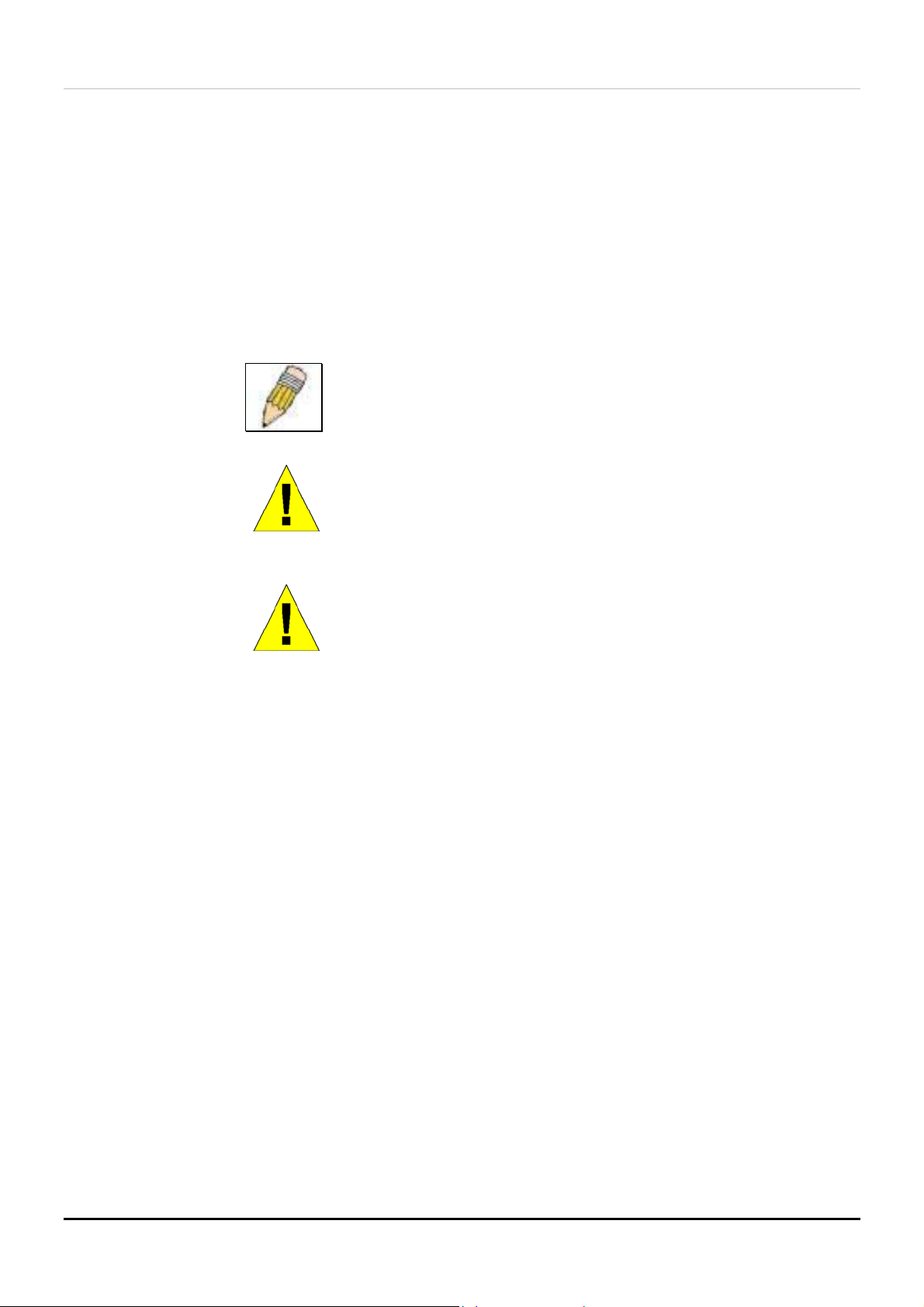
NOTE: A qualified electrician must perform all connections to DC power
and to safety grounds. All electrical wiring must comply with applicable
local or national codes and practices.
CAUTION: Never defeat the ground conductor or operate the equipment
in the absence of a suitably installed ground conductor. Contact the
appropriate electrical inspection authority or an electrician if you are
uncertain that suitable grounding is available.
CAUTION: The system chassis must be positively grounded to the rack
cabinet frame. Do not attempt to connect power to the system until
grounding cables are connected. Completed power and safety ground
wiring must be inspected by a qualified electrical inspector. An energy
hazard will exist if the safety ground cable is omitted or disconnected.
Protecting Against Electrostatic Discharge
Static electricity can harm delicate components inside your system. To prevent static damage, discharge static electricity from
your body before you touch any of the electronic components, such as the microprocessor. You can do so by periodically
touching an unpainted metal surface on the chassis.
You can also take the following steps to prevent damage from electrostatic discharge (ESD):
1. When unpacking a static-sensitive component from its shipping carton, do not remove the component from
the antistatic packing material until you are ready to install the component in your system. Just before
unwrapping the antistatic packaging, be sure to discharge static electricity from your body.
2. When transporting a sensitive component, first place it in an antistatic container or packaging.
3. Handle all sensitive components in a static-safe area. If possible, use antistatic floor pads and workbench
pads and an antistatic grounding strap.
x
Page 11

D-Link DES-3250TG Standalone Layer 2 Switch
Introduction
Fast Ethernet Technology
Gigabit Ethernet Technology
Switch Stacking
Performance Features
Ports
This section describes the functionality features of the DES-3250TG.
Section 1
Fast Ethernet Technology
100Mbps Fast Ethernet (or 100BASE-T) is a standard specified by the IEEE 802.3 LAN committee. It is an extension of the
10Mbps Ethernet standard with the ability to transmit and receive data at 100Mbps, while maintaining the Carrier Sense
Multiple Access with Collision Detection (CSMA/CD) Ethernet protocol.
Gigabit Ethernet Technology
Gigabit Ethernet is an extension of IEEE 802.3 Ethernet utilizing the same packet structure, format, and support for full duplex
and management objects, but with a tenfold increase in theoretical throughput over 100Mbps Fast Ethernet and a one hundredfold increase over 10Mbps Ethernet. Since it is compatible with all 10Mbps and 100Mbps Ethernet environments, Gigabit
Ethernet provides a straightforward upgrade without wasting a company’s existing investment in hardware, software, and
trained personnel.
Switch Stacking
The DES-3250TG can be used as a standalone or a stacked Switch by using the optional stacking module. Up to 12 Switches
may be stacked and managed as a unit with a single IP address. Management for the entire stack is done through the Master
Switch. You may add Switches later as needed. The Switch can also be grouped in a stack as a slave with the DES-3312SL
Switch (acting as the Master).
1
Page 12

D-Link DES-3250TG Standalone Layer 2 Switch
Features
The DES-3250TG Switch was designed for easy installation and high performance in an environment where traffic on the
network and the number of users increase continuously.
Switch features include:
• Store and forward switching scheme.
• Full and half-duplex for both 10Mbps and 100Mbps connections. The front-port Gigabit Ethernet module operates at
full duplex only. Full duplex allows the switch port to simultaneously transmit and receive data, and only works with
connections to full-duplex capable end stations and switches. Connections to hubs must take place at half-duplex.
• Auto-polarity detection and correction of incorrect polarity on the transmit and receive twisted-pair at each port.
• IEEE 802.3z compliant for Mini GBIC ports (optional module).
• IEEE 802.3ab compliant for 1000BASE-T (Copper) Gigabit ports (optional module).
• Data forwarding rate 14,880 pps per port at 100% of wire-speed for 10Mbps speed.
• Data forwarding rate 148,800 pps per port at 100% of wire-speed for 100Mbps speed.
• Data filtering rate eliminates all error packets, runts, etc. at 14,880 pps per port at 100% of wire-speed for 10Mbps
speed.
• Data filtering rate eliminates all error packets, runts, etc. at 148,800 pps per port at 100% of wire-speed for 100Mbps
speed.
• 8K active MAC address entry table per device with automatic learning and aging (10 to 1,000,000 seconds).
• 64 MB packet buffer per device.
• Supports Port Mirroring.
• Supports Port Trunking.
• 802.1D Spanning Tree support.
• 802.1Q Tagged VLAN support – up to 255 VLANs per device (one VLAN is reserved for internal use).
• GVRP – (GARP VLAN Registration Protocol) support for dynamic VLAN registration.
• 802.1p Priority support with 4 priority queues.
• IGMP Snooping support.
Ports
• Forty-eight high-performance NWay ports all operating at 10/100 Mbps for connecting to end stations, servers and
hubs.
• All 48 10/100 UTP ports can auto-negotiate (NWay) between 10Mbps/100Mbps, half-duplex or full duplex.
• One front panel slide-in module interface for a 2-port 1000BASE-T module (provided) and one front panel slide-in
module interface for a 2-port Mini GBIC Gigabit Ethernet module (optional). Please note that although these two front
2
Page 13

D-Link DES-3250TG Standalone Layer 2 Switch
panel modules can be used simultaneously, the ports must be different. For example, if port 49x is used on the Mini
GBIC module, port 49x is not available on the 1000BASE-T module, and vice versa.
• RS-232 DCE Diagnostic port (console port) for setting up and managing the Switch via a connection to a console
terminal or PC using a terminal emulation program.
Traffic Classification and Prioritization
• Based on 802.1p priority bits.
• Four priority queues.
Management
• RS-232 console port for out-of-band network management via a console terminal or PC.
• Fast Spanning Tree Algorithm Protocol for creation of alternative backup paths and prevention of network loops.
• SNMP V1, V2C, and V3 are supported.
• Fully configurable in-band control for SNMP based software.
• Flash memory for software upgrades. This can be done in-band via TFTP or out-of-band via the console.
• Built-in SNMP management:
SNMP V2-MIB (RFC 1907).
Bridge MIB (RFC 1493).
MIB-II (RFC 1213).
IF MIB (RFC 2233).
Entity MIB (RFC 2737).
RMON MIB (RFC 1757) – 4 groups. The RMON specification defines the Counters for the Receive function
only. However, the DES-3250TG implements counters for both receive and transmit functions.
802.1p MIB (RFC 2674).
Ether-Like MIB (RFC 2358) – dot3StatsTable.
• Supports Web-based management.
• CLI management support.
• TFTP support.
• BOOTP support.
• DHCP Client support.
• Password enabled.
3
Page 14

D-Link DES-3250TG Standalone Layer 2 Switch
Unpacking and Setup
Unpacking
Installation
Power On
This chapter provides unpacking and setup information for the Switch.
Unpacking
Section 2
Open the shipping carton of the Switch and carefully unpack its contents. The carton should contain the following items:
• One DES-3250TG Standalone Layer 2 Switch
• Mounting kit: 2 mounting brackets and screws
• Four rubber feet with adhesive backing
• One AC power cord
• This User’s Guide with Registration Card
If any item is found missing or damaged, please contact your local D-Link reseller for replacement.
Installation
Use the following guidelines when choosing a place to install the Switch:
• The surface must support at least 5 kg
• The power outlet should be within 1.82 meters (6 feet) of the device
• Visually inspect the power cord and see that it is secured to the AC power connector
• Make sure that there is proper heat dissipation from and adequate ventilation around the switch. Do not place
heavy objects on the switch
Desktop or Shelf Installation
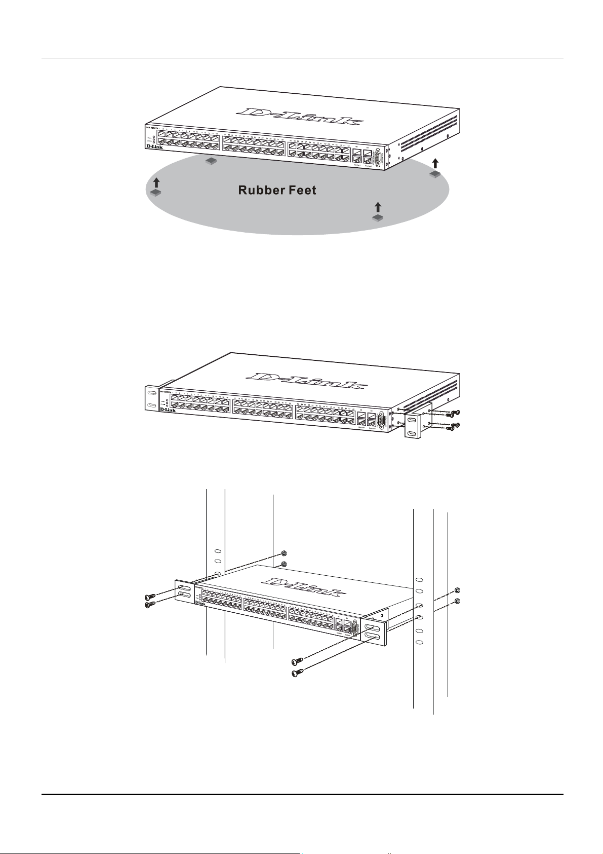
When installing the Switch on a desktop or shelf, the rubber feet included with the device should first be attached. Attach these
cushioning feet on the bottom at each corner of the device. Allow adequate space for ventilation between the device and the
objects around it.
4
Page 15
D-Link DES-3250TG Standalone Layer 2 Switch
Figure 2-1. Installing rubber feet for desktop installation
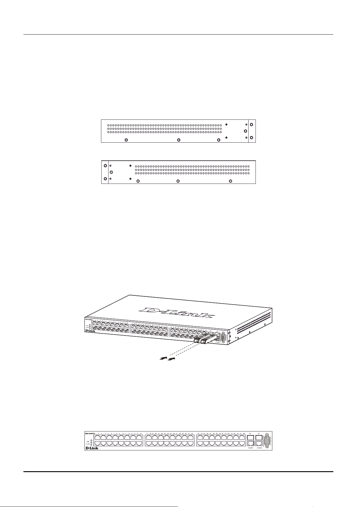
Rack Installation
The DES-3250TG can be mounted in an EIA standard-sized, 19-inch rack, which can be placed in a wiring closet with other
equipment. To install, attach the mounting brackets on the switch’s side panels (one on each side) and secure them with the
screws provided.
Figure 2- 2. Attaching the mounting brackets to the switch
Then, use the screws provided with the equipment rack to mount the switch on the rack.
Figure 2-3. Installing the switch on an equipment rack
5
Page 16

D-Link DES-3250TG Standalone Layer 2 Switch
Power on
The DES-3250TG switch can be used with AC power supply 100 - 240 VAC, 50 - 60 Hz. The power switch is located at the
rear of the unit adjacent to the AC power connector and the system fan. The switch’s power supply will adjust to the local
power source automatically and may be turned on without having any or all LAN segment cables connected.
After the power switch is turned on, the LED indicators should respond as follows:
• All LED indicators will momentarily blink. This blinking of the LED indicators represents a reset of the system
The power LED indicator is always on after the power is turned ON
•
• The console LED indicator will blink while the Switch loads onboard software and performs a self-test. It will
remain ON if there is a connection at the RS-232 port, otherwise this LED indicator is OFF
Power Failure
As a precaution in the event of a power failure, unplug the switch. When the power supply is restored, plug the switch back in.
6
Page 17
D-Link DES-3250TG Standalone Layer 2 Switch
Section 3
Identifying External Components
Front Panel
Rear Panel
Side Panels
Gigabit Combo Ports
LED Indicators
This chapter describes the front panel, rear panel, side panels, and optional plug-in module, and LED indicators of the
DES-3250TG.
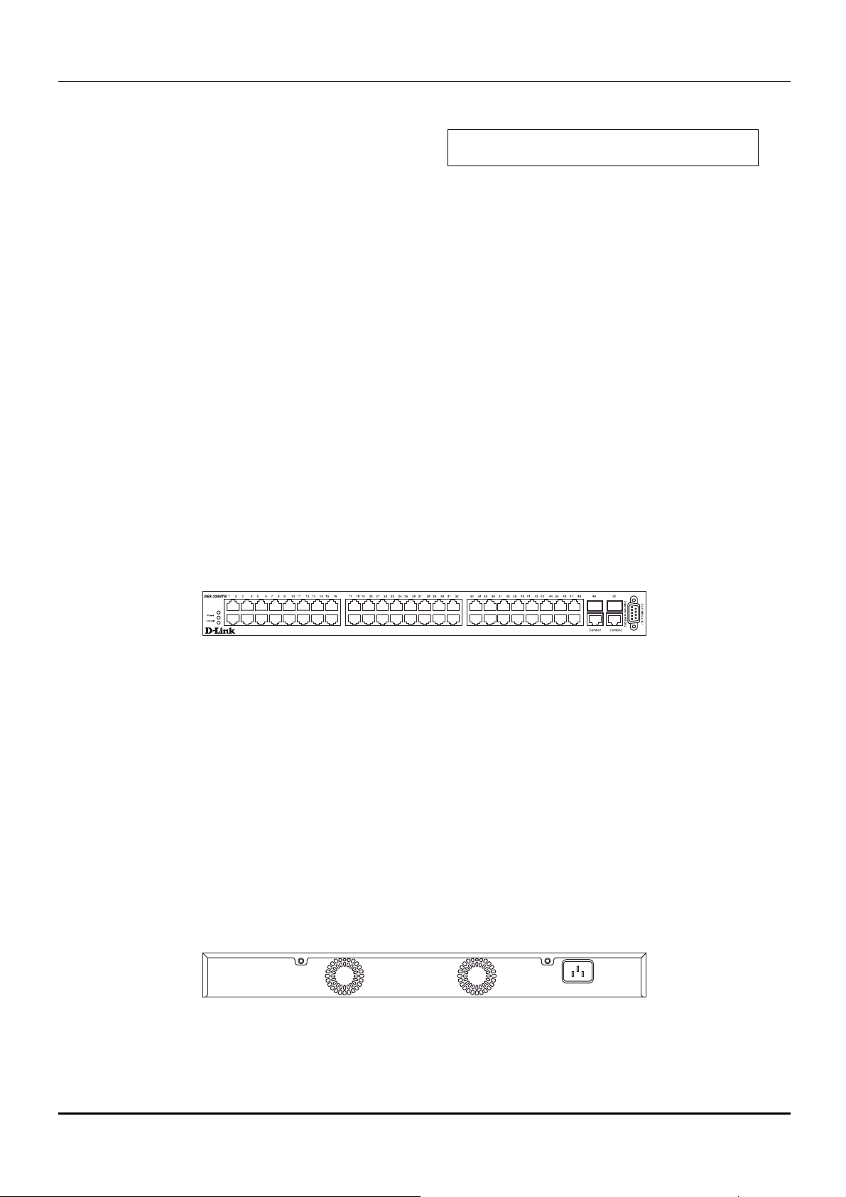
Front Panel
The front panel of the Switch consists of LED indicators, an RS-232 communication port, 48 (10/100 Mbps) Ethernet/Fast
Ethernet ports, and a pair of Gigabit Ethernet Combo ports for 1000BASE-T (plug-in module provided) and Mini GBIC
connections (optional plug-in module).
Figure 3-1. Front panel view of the Switch
● Comprehensive LED indicators display the status of the switch and the network (see the LED Indicators section
below).
● An RS-232 DCE console port for setting up and managing the switch via a connection to a console terminal or PC
using a terminal emulation program.
● Forty-eight high-performance NWay Ethernet ports, all of which operate at 10/100 Mbps for connections to end
stations, servers and hubs. All ports can auto-negotiate between 10Mbps or 100Mbps and full or half duplex.
● Two Gigabit Ethernet Combo ports for making 1000BASE-T and Mini GBIC connections.
Rear Panel
The rear panel of the switch consists of two fans and an AC power connector.
Figure 3-2. Rear panel view of the Switch
The system fans are used to dissipate heat. The sides of the system also provide heat vents to serve the same purpose. Do not
block these openings, and leave at least 6 inches of space at the rear and sides of the switch for proper ventilation. Be reminded
that without proper heat dissipation and air circulation, system components might overheat, which could lead to system failure.
7
Page 18
D-Link DES-3250TG Standalone Layer 2 Switch
The AC power connector is a standard three-pronged connector that supports the power cord. Plug-in the female connector of
the provided power cord into this socket, and the male side of the cord into a power outlet. Supported input voltages range
from 100 ~ 240 VAC at 50 ~ 60 Hz.
Side Panels
Each side panel contains heat vents to help to dissipate heat.
Figure 3-3. Side panel views of the Switch
The system fans are used to dissipate heat. The sides of the system also provide heat vents to serve the same purpose. Do not
block these openings, and leave at least 6 inches of space at the rear and sides of the switch for proper ventilation. Be reminded
that without proper heat dissipation and air circulation, system components might overheat, which could lead to system failure.
Gigabit Combo Ports
In addition to the 48 10/100 Mbps ports, the Switch features two Gigabit Ethernet Combo ports. These two ports are
1000BASE-T copper ports (provided) and Mini-GBIC ports (optional). See the diagram below to view the two Mini-GBIC
port modules being plugged into the Switch. Please note that although these two front panel modules can be used
simultaneously, the ports must be different. The GBIC port will always have the highest priority.
Figure 3-4. Mini-GBIC modules plug-in to the Switch
LED Indicators
The LED indicators of the Switch include Power, Console, and Link/Act. The following shows the LED indicators for the
Switch along with an explanation of each indicator.
Figure 3-5. The LED Indicators
8
Page 19

D-Link DES-3250TG Standalone Layer 2 Switch
● Power – This indicator on the front panel should be lit during the Power-On Self Test (POST). It will light green
approximately 2 seconds after the switch is powered on to indicate the ready state of the device.
● Console – This indicator is lit green when the switch is being managed via local console management through the
RS-232 console port.
● Link/Act – These indicators are located to the left and right of each port. They are lit when there is a secure
connection (or link) to a device at any of the ports. The LEDs blink whenever there is reception or transmission (i.e.
Activity--Act) of data occurring at a port.
9
Page 20
D-Link DES-3250TG Standalone Layer 2 Switch
Section 4
Connecting the Switch
Switch to End Node
Switch to Hub or Switch
10BASE-T Device
100BASE-TX Device
Stacking vs. Standalone Operation
Managing Switch Stacks
This chapter describes how to connect the DES-3250TG to your Ethernet/Fast Ethernet/Gigabit Ethernet network. The
Switch’s auto-detection feature allows all 48 10/100 ports to support both MDI-II and MDI-X connections.
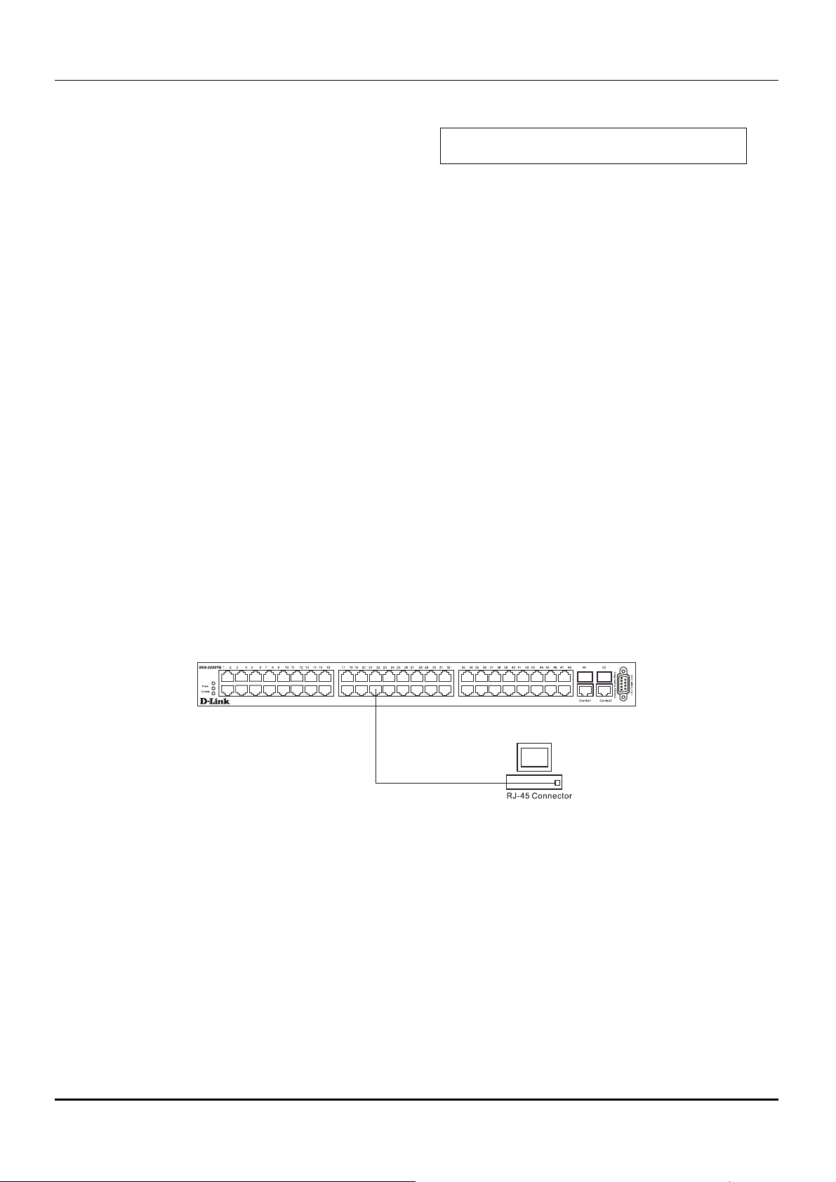
Switch to End Node
End nodes include PCs outfitted with a 10, 100, or 10/100 Mbps RJ-45 Ethernet/Fast Ethernet Network Interface Card (NIC)
and most routers.
An end node can be connected to the Switch via a two-pair Category 3, 4, or 5 UTP/STP cable. The end node should be
connected to any of the ports (1x - 48x) on the switch.
Figure 4- 1. Switch connected to an End Node
The Link/Act LEDs in the top row for each UTP port light green when the link is valid. A blinking LED in the top row
indicates packet activity on that port.
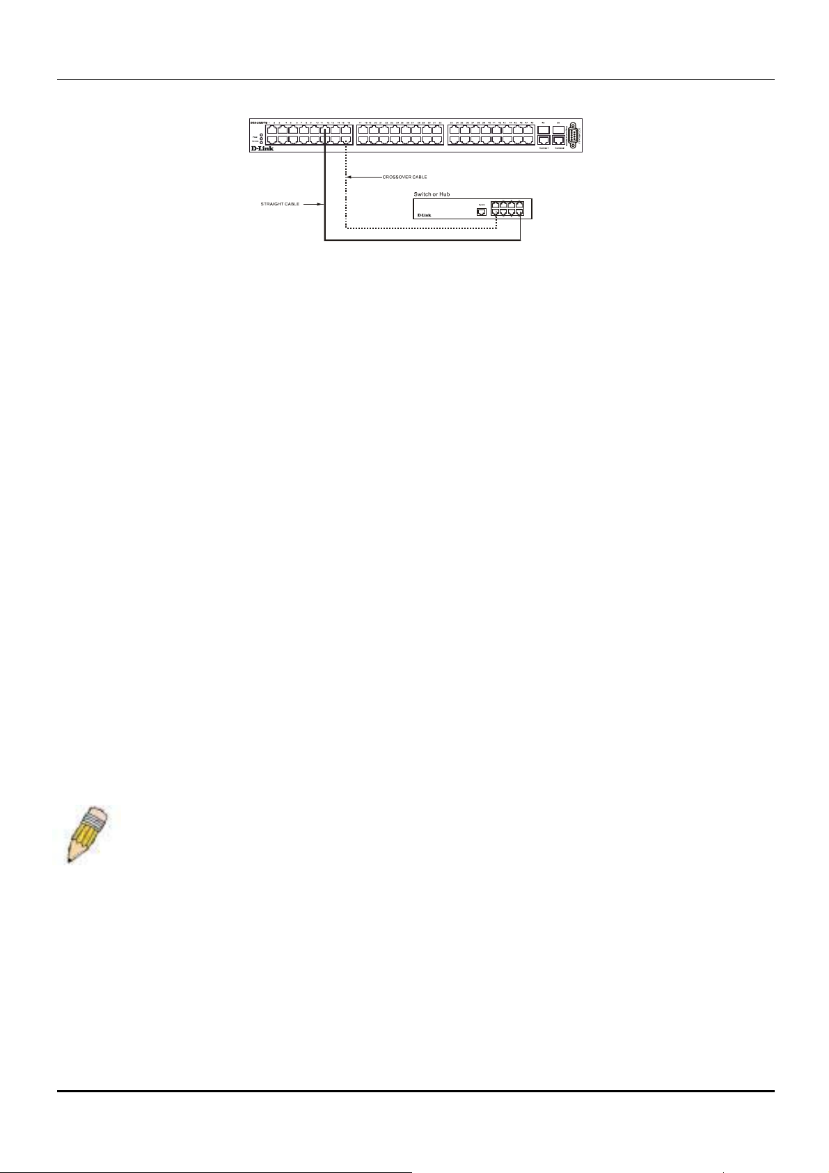
Switch to Hub or Switch
These connections can be accomplished in a number of ways using a normal cable.
● A 10BASE-T hub or switch can be connected to the Switch via a two-pair Category 3, 4 or 5 UTP/STP cable.
● A 100BASE-TX hub or switch can be connected to the Switch via a two-pair Category 5 UTP/STP cable.
10
Page 21
D-Link DES-3250TG Standalone Layer 2 Switch
Figure 4- 2. Switch connected to a port on a hub or switch using a straight or crossover cable
10BASE-T Device
For a 10BASE-T device, the Switch’s LED indicators should display the following:
● Link/Act indicator is ON.
100BASE-TX Device
For a 100BASE-TX device, the Switch’s LED indicators should display the following:
● Link/Act is ON.
Stacking vs. Standalone Operation
By default, the Switch configuration settings allow it to operate as a standalone device, or in a stacked group. It is not
necessary to change any settings for the Switch to function in either capacity. However, it is useful to understand how the
stacking mode operates in the Switch and the effects if any this may have on configuration settings in a Switch when its
stacking status is changed.
Stacking mode is enabled by default and can be changed using the CLI command config stacking mode. If the Switch has
stacking mode enabled and is properly connected to other DES-3250TG Switches, a negotiation takes place upon starting up
the Switches to determine how the Switch functions in the stack. For an all-DES-3250TG stack, any time a change occurs in
the structure or composition of a stacked Switch group the entire stack will restart and the negotiation process begins anew.
When the stacking mode is disabled (config stacking mode disable), the Switch only allows standalone operation. If
stacking mode is disabled on a Switch, it should be disconnected from a stacked group.
NOTE: The firmware for Release 4 allows stacking operation of the DES-3250TG as a slave to the
DGS-3312SR in a star topology. See the example below for more information.
Stacking mode can be changed using the CLI. When a DES-3250TG Switch stack is first assembled, it is advisable to
determine which Switch will function as the master before placing the Switches in a rack and connecting them. If the Switch is
used in a stacked group with the DGS-3312SR, the DGS-3312SR operates as the master and the DES-3250TG Switches in the
stacked group operate as slaves. The possible stacking configuration modes are as follows:
Enabled: Stacking mode is enabled by default. When enabled the Switch can operate as a standalone device or it can operate
with other DES-3250TG Switches in a properly connected stacked group. Stacking must be enabled for the Switch to function
in a stacked arrangement with other DES-3250TG Switches or with a DGS-3312SR Switch.
Auto: This is the default stacking mode setting for the DES-3250TG. In auto stacking mode, the Switch is eligible for stacking
or it can operate as a standalone device. If a DES-3250TG Switch stack is connected and all units are configured to operate in
11
Page 22

D-Link DES-3250TG Standalone Layer 2 Switch
auto stacking mode, the master-slave relationships is determined automatically. For DES-3250TG Switch stacks, the unit with
the lowest MAC address becomes the master (stack number 1). The order in which slave devices appear logically in the stack
(stack number 2+) is determined by how they are connected relative to the master Switch. The auto mode serves to first
determine if the device is stacked or standalone, then if stacked, it determines which Switch is the master and the remaining
stack numbers for the slave Switches.
Master: The auto mode described above may be overridden so that a properly connected Switch in a stack may be forced into
master mode. Only one Switch in a stack may act as the master and all configuration settings for the stacked group - including
stacking configuration - are saved in configuration files in the master Switch. The stack is managed as a single entity through
the master. It may be convenient to place the master unit in the upper-most slot of a stacked group to visually distinguish it
form the slave units. The master unit should be used to uplink the stack group to the backbone. If the master unit fails or is
replaced for any reason, it is possible to load configuration files saved from the original master unit in order to continue
operation with identical settings. See the example below for a description of how to swap the master unit of a stacked group. A
Switch configured as the stack master will maintain this status regardless of any changes that occur in the composition of the
stacked group. If for example a connection to a slave unit or a connection between two slave units were to fail, the entire stack
will restart automatically. After restarting, the designated master unit retains its status.
Slave: The auto mode may be overridden to force the Switch to operate in slave mode. When the Switch is in slave mode, it is
ineligible to function as a master and all configuration, is done through the master unit. A master Switch must be properly
connected to the stack for a Switch to operate in slave mode.
Disabled: This forces the Switch to operate as a standalone device. In standalone mode the Switch functions as a standalone
device even if a stacking module is installed. To force standalone operation it is necessary to use the CLI command
config stacking mode disable. A Switch that has stacking mode disabled should never connect to another
Switch through stacking ports.
NOTICE: Do not use stacking ports on a Switch that has the stacking mode disabled.
For DES-3250TG Switch stacks, changes made to the composition of a Switch stack group, that is, adding new Switches or
taking Switches out of the stack, require all Switches to restart. The new stacking order is negotiated to reflect the changes
made to the group. If the master Switch has been configured to force master status it retains this status, likewise Switches
forced to operate in slave mode retain the status after restarting. The restart occurs automatically if any stacking link is
disconnected.
For star topology arrangements, the DGS-3312SR Switches do not restart when a link or Switch failure occurs. Only the
effected Switch will restart if its link to the DGS-3312SR Switch fails. The remaining DES-3250TG Switches continue to
operate as before.
The command show stacking can be used to view stacking information. If stacking has been disabled, the stacking mode will
be listed as Standalone.
Managing Switch Stacks
Multiple DES-3250TG Switches equipped with stacking modules may be connected in a stacking arrangement so that up to
twelve Switches are managed as a single unit with a single IP address. The Release 4 DES-3250TG can connect to the DGS3312SR via the stacking port in a star topology. Up to twelve Switches may be connected to the DGS-3312SR and be managed
as slave devices through the DGS-3312SR Switch.
The default stacking mode will establish a master Switch for the stack through a negotiation process that takes place when all
devices are started up. In a DES-3250TG stack, the Switches negotiate the master-slave relationship. Once the master Switch is
determined, the remaining Switches function as slaves. The stack number of the slave Switches is determined by where it is
actually positioned in the stack. This can be taken into account when you are placing the Switches in an equipment rack.
For star topology stacking arrangements with the DGS-3312SR, the default settings of the DES-3250TG assign slave status
and the unit number is determined by the number of the port connected at the other end of the stacking connection.
12
Page 23
D-Link DES-3250TG Standalone Layer 2 Switch
Keep in mind the following important considerations for stacked Switch groups:
All management of the Switches in the stack is done through the master Switch. •
• The master Switch should be used to uplink to the Ethernet backbone.
For DES-3250TG stacks, the master Switch can be chosen automatically as each Switch in a connected stack competes for
status. However, you can choose a specific device and force it to operate as the master. Use the CLI command
stacking mode enabled master
for the selected Switch; leave the remaining Switches in the default auto-
config
stacking mode.
For DES-3250TG stacks, if the link between any two Switches fails or is disconnected, or if any Switch in a stacked group
fails, all of the Switches in the stack will automatically reboot. Since the stack is connected as a ring, the stack will need to be
connected to work around the failed link. Change the cabling to bypass the failed link and allow the stack to reboot. The
Switches will negotiate again since the composition of the stack has been altered. Read below for more information about
changes in stacked Switch groups.
A Switch stack has a single IP address − if the stacking link to a given Switch fails or is disconnected, that Switch will loose its
status in the stack and reboot as a standalone device with the IP settings it had before becoming a member of the Switch stack.
NOTE: For Release 4 the DES-3250TG maintains two separate configurations, one for standalone
operation and another for stacked operation. Each configuration has identical IP settings, VLANs, link
aggregation, QoS, etc. This dual system allows a Switch to change status from standalone to
stacking enabled and keep its configuration settings.
Changes to Switch Stack Structure
If Switches are added to or taken out of a stacked group of DES-3250TG Switches it is necessary to change the composition of
a Switch stack and rearrange the stacking connections. If a stacking link fails or if a member of a stacked group fails, the
composition of the stack will necessarily change also. In such a case intervention is required to at least reconnect the stacking
cable to bypass the failure. In addition to making changes to the cable links connecting the Switches in the stack, it may be
necessary or desirable to change the stacking mode configuration of one or more units. A few examples presented below to
help make the changes to cable connections for DES-3250TG stacks and if necessary, to Switch stacking mode configuration
settings.
NOTE: For a Switch that has already been configured with many settings already in place, it is a good
idea to save the configuration files to a server before changing the stacking mode status.
Configuration files can be saved using the CLI, SNMP manager or web manager interface.
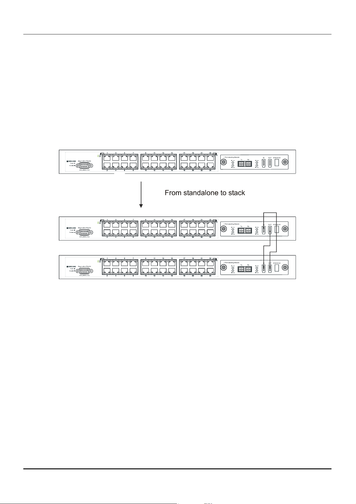
Convert a Standalone Switch to a Stacked Switch
A Switch that has previously acted in a standalone capacity may become a member of a stacked group simply by installing a
stacking module and connecting it to a connected Switch stack. For this example, let’s assume Switch A has been setup as a
standalone device and has been functioning on the network. We want to join this Switch with another DES-3250TG, Switch B,
to form a 2-Switch stack. Many configuration settings including IP settings have already been set on Switch A so we will keep
these and use them for the new stacked arrangement. Switch A is also uplinked to the backbone via the GBIC port in the
stacking module. Switch A will stay in its position in the uppermost slot in the rack and all network connections will remain in
place.
First, save the configuration files to a TFTP server so they may be reloaded if any problems occur. This should be done
whether or not stacking mode is changed.
13
Page 24
D-Link DES-3250TG Standalone Layer 2 Switch
Since we want to keep the same IP address and all the other settings on the standalone Switch, this Switch will become the
master of the stack and Switch B will become the slave. To make sure Switch A functions as the master we will enable
stacking and override the auto function.
Use the CLI to enter the command:
config stacking mode enable master
The stacking mode for Switch B is set to the default auto-stacking mode and therefore no changes are required. Switch B will
lose configuration settings including its IP settings, so if you want to save these be sure to upload the configuration files before
making the stacking connection.
Power off both devices and place Switch B under Switch A in the rack. It is not actually required that the slave device be
placed under the master in the stack but it may be easier so that the master Switch may be instantly recognized. This may prove
especially convenient where multiple Switch stacks are installed so it is always clear which unit should be used to uplink.
Figure 4- 3. Convert a Standalone Switch to a Stacked Switch
Both Switches are now powered off. Switch B is placed securely in the rack and connected to Switch A via the stacking ports.
Both devices are powered on; they recognize the stacking connection and begin negotiating the stacking relationship. Switch A
is configured to function as the master device. Switch B automatically assume slave status. Switch A will keep its IP settings
and its other configurations remain unchanged. The stack may now be configured as a single entity.
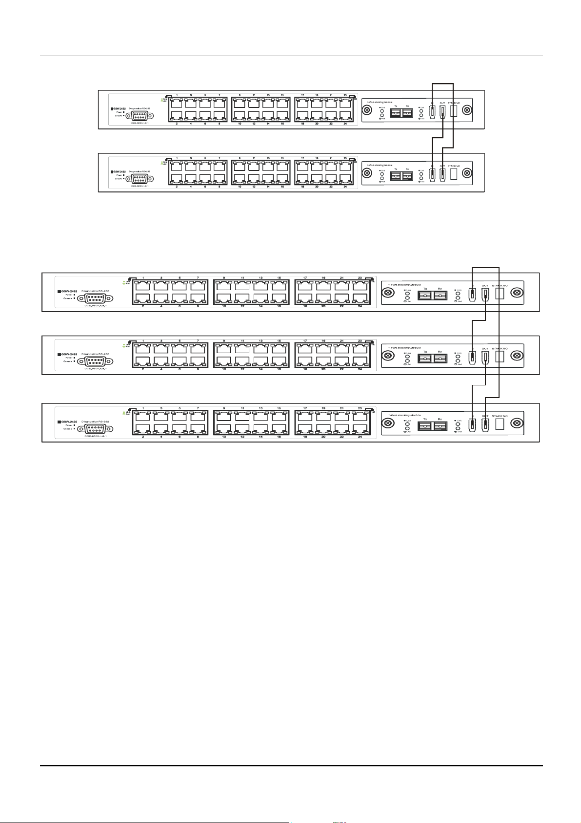
Add a Switch to a Stack
Adding a new slave device to a Switch stack is a simple procedure. If you are swapping an existing Switch, label each Ethernet
cable attached to the device being swapped so they can be placed in the same port number in the replacement device.
To add a new slave to a stack, place the new unit in the next available slot below the stack. Power off all Switches in the stack
and make the necessary changes to the stacking cable connections. Use the illustrations below as a guide.
14
Page 25
D-Link DES-3250TG Standalone Layer 2 Switch
Figure 4- 4. Add a Switch to a Stack
Switch C is added to the existing stack where Switch A is the designated master. Power off all devices and securely place
Switch C in the slot beneath Switch B. Adjust stacking cable connections so the OUT port on Switch B connects the IN port on
Switch C and the OUT port of Switch C connects to the IN port of Switch A.
Figure 4- 5. Add a third Switch to a stack
Power on the entire stack. The new stacking arrangement is recognized and the new relationship is negotiated. Switch A retains
status as the master of the stack, Switch C is in auto mode and therefore functions as a slave. The stack is ready for operation.
Swap a Master from a Stack
Let’s assume the stack arrangement in the previous example has a problem that requires the master unit, Switch A, to be
replaced. In this case, we can preserve all the same configuration settings by downloading the previously saved configuration
files to the replacement Switch.
Before disconnecting the network connections of the original master unit, label each Ethernet cable so they can be placed in the
same port number in the replacement Switch. Then remove the device from the rack.
Place the replacement Switch in the same slot. Power on the new Switch and attach a console cable to it. Configure the new
unit to be a master and save the settings. Connect the Ethernet cable needed to access the TFTP server containing the saved
configuration files of the previous master unit. Download the saved configuration files, use the command:
download configuration <ipaddr> <path_filename>
Save the new settings and power off the Switch. Now the stacking connections and Ethernet connections can be completed
exactly as before. Reconnect the stacking cables and Ethernet connections and power on the entire stack. The stack should now
function as before with all the configuration settings intact.
15
Page 26
D-Link DES-3250TG Standalone Layer 2 Switch
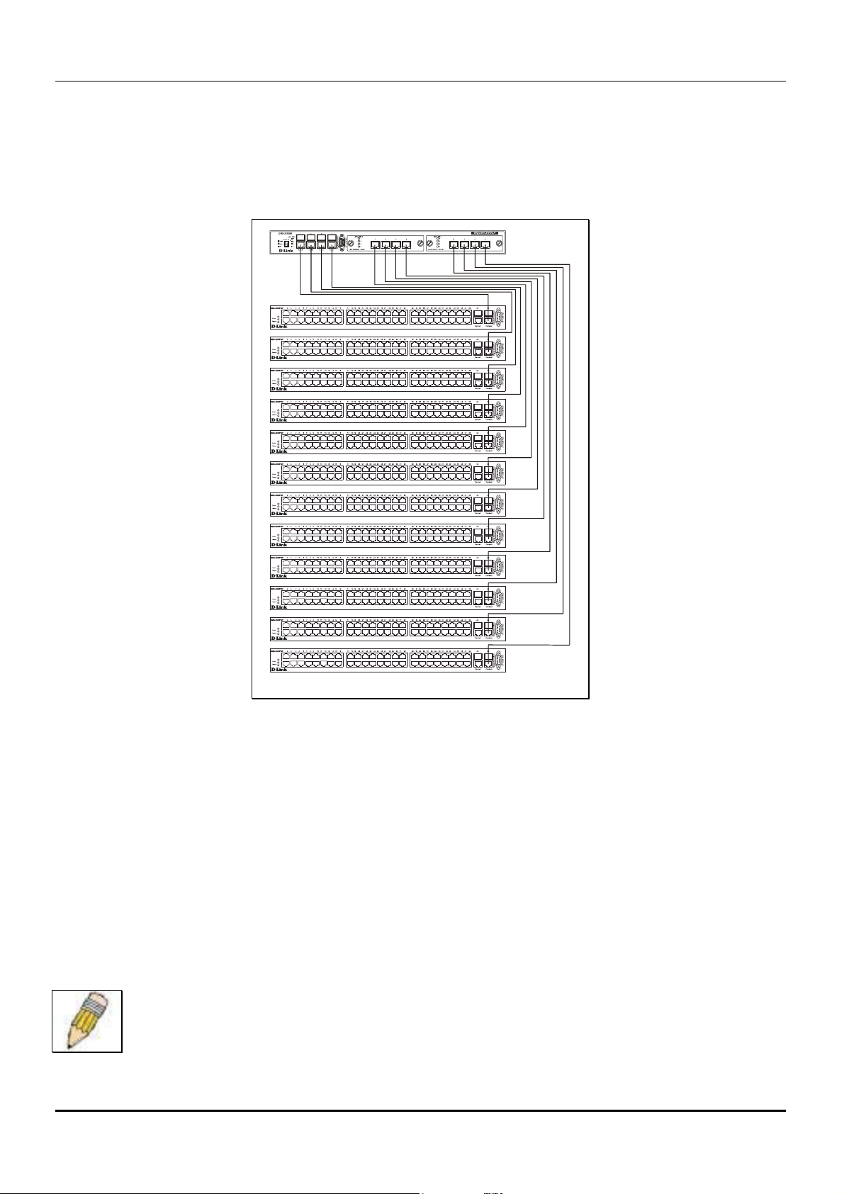
Stacking with DGS-3312SR
The DES-3250TG Release 4 Switch can be arranged in a star topology and managed as slave devices through the DGS3312SR Master Switch. Up to twelve Switches can be connected to the DGS-3312SR Switch in this arrangement.
Figure 4- 6. DES-3250TG Switches with DGS-3312SR
Setting up a star topology with a DGS-3312SR is a simple matter. Each DES-3250TG connects to the master through the
stacking port to a similar stacking port on a DGS-3312SR Switch equipped with one or two special stacking modules designed
for the DES-3250TG Switch. Each DES-3250TG slave must be configured with stacking mode enabled. When stacked in a
star topology arrangement with the DGS-3312SR, the Switch will automatically assume slave status. The unit number is
determined by the port number to which it is connected on the DGS-3312SR master. The DGS-3312SR must have a stacking
module installed and have stacking mode enabled as well. Stacking for the DGS-3312SR uses the identical CLI command:
config stacking mode enable. Be sure to save the configuration change using the CLI command save.
Remember that for star topology arrangements, if the stacking link to a given Switch fails or is disconnected, that Switch will
lose its status in the stack and reboot as a standalone device with the IP settings. The DGS-3312SR and remaining slave units
are not effected by the link failure.
NOTE: The DES-3250TG must have stacking mode enabled to be used with the DGS-3312SR in a
star topology arrangement.
16
Page 27

D-Link DES-3250TG Standalone Layer 2 Switch
Section 5
Introduction to Switch Management
Management Options
Web-based Management Interface
SNMP-Based Management
Managing User Accounts
Command Line Console Interface through the Serial Port
Connecting the Console Port (RS-232 DCE)
First Time Connecting to the Switch
Password Protection
SNMP Settings
IP Address Assignment
Connecting Devices to the Switch
Management Options
This system may be managed out-of-band through the console port on the front panel or in-band using Telnet. The user may
also choose the web-based management, accessible through a web browser.
Web-based Management Interface
After you have successfully installed the Switch, you can configure the Switch, monitor the LED panel, and display statistics
graphically using a web browser, such as Netscape Navigator (version 6.2 and higher) or Microsoft® Internet Explorer
(version 5.0).
SNMP-Based Management
You can manage the Switch with an SNMP-compatible console program. The Switch supports SNMP version 1.0, version 2.0
and version 3.0. The SNMP agent decodes the incoming SNMP messages and responds to requests with MIB objects stored in
the database. The SNMP agent updates the MIB objects to generate statistics and counters.
Command Line Console Interface Through the Serial Port
You can also connect a computer or terminal to the serial console port to access the Switch. The command-line-driven interface
provides complete access to all Switch management features.
17
Page 28

D-Link DES-3250TG Standalone Layer 2 Switch
Connecting the Console Port (RS-232 DCE)
The Switch provides an RS-232 serial port that enables a connection to a computer or terminal for monitoring and configuring
the Switch. This port is a female DB-9 connector, implemented as a data terminal equipment (DTE) connection.
To use the console port, you need the following equipment:
A terminal or a computer with both a serial port and the ability to emulate a terminal. •
• A null modem or crossover RS-232 cable with a female DB-9 connector for the console port on the Switch.
To connect a terminal to the console port:
1. Connect the female connector of the RS-232 cable directly to the console port on the Switch, and tighten the captive
retaining screws.
2. Connect the other end of the cable to a terminal or to the serial connector of a computer running terminal emulation
software. Set the terminal emulation software as follows:
3. Select the appropriate serial port (COM port 1 or COM port 2).
4. Set the data rate to 9600 baud.
5. Set the data format to 8 data bits, 1 stop bit, and no parity.
6. Set flow control to none.
7. Under Properties, select VT100 for Emulation mode.
8. Select Terminal keys for Function, Arrow, and Ctrl keys. Ensure that you select Terminal keys (not Windows keys).
NOTE: When you use HyperTerminal with the Microsoft® Windows® 2000
operating system, ensure that you have Windows 2000 Service Pack 2 or
later installed. Windows 2000 Service Pack 2 allows you to use arrow keys in
HyperTerminal's VT100 emulation. See www.microsoft.com for information
on Windows 2000 service packs.
9. After you have correctly set up the terminal, plug the power cable into the power receptacle on the back of the Switch.
The boot sequence appears in the terminal.
10. After the boot sequence completes, the console login screen displays.
11. Usernames and Passwords are not required on the initial screen after the first connection. Any additional user names
and passwords must first be created by the administrator. If you have previously set up user accounts, log in and
continue to configure the Switch.
12. Enter the commands to complete your desired tasks. Many commands require administrator-level access privileges.
Read the next section for more information on setting up user accounts. See the DES-3250TG Command Line
Interface Reference Manual on the documentation CD for a list of all commands and additional information on using
the CLI.
13. When you have completed your tasks, exit the session with the logout command or close the emulator program.
Make sure the terminal or PC you are using to make this connection is configured to match these settings.
If you are having problems making this connection on a PC, make sure the emulation is set to VT-100. You will be able to set
the emulation by clicking on the File menu in you HyperTerminal window, clicking on Properties in the drop-down menu, and
then clicking the Settings tab. This is where you will find the Emulation options. If you still do not see anything, try rebooting
the Switch by disconnecting its power supply.
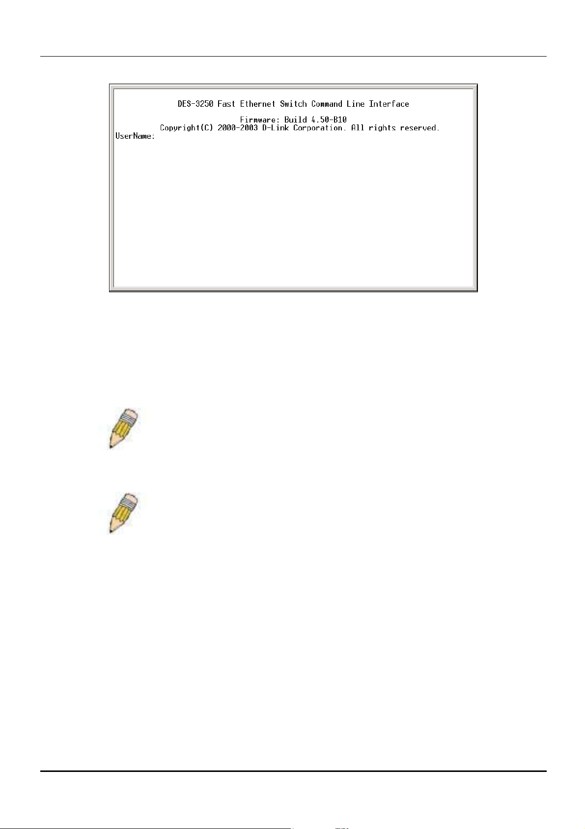
Once connected to the console, the screen below will appear on your console screen. This is where the user will enter
commands to perform all the available management functions. The Switch will prompt the user to enter a user name and a
password. Upon the initial connection, the user name and password are not required. These can be changed or deleted later.
18
Page 29
D-Link DES-3250TG Standalone Layer 2 Switch
Figure 5- 1. Initial screen after first connection
First Time Connecting to The Switch
The Switch supports user-based security that can allow you to prevent unauthorized users from accessing the Switch or
changing its settings. This section tells how to log onto the Switch.
NOTE: The passwords used to access the Switch are case-sensitive;
therefore, "S" is not the same as "s."
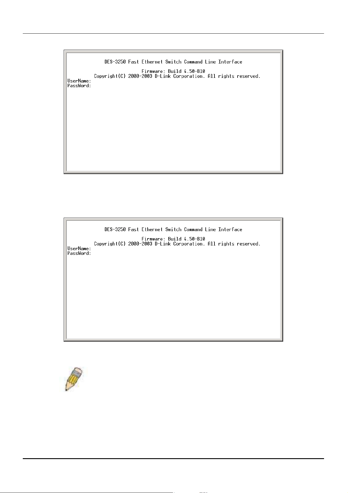
When you first connect to the Switch, you will be presented with the first login screen (shown below).
NOTE: Press Ctrl+R to refresh the screen. This command can be used at any
time to force the console program in the Switch to refresh the console screen.
19
Page 30
D-Link DES-3250TG Standalone Layer 2 Switch
Figure 5- 2. Initial screen, first time connecting to the Switch
Usernames and Passwords are not required on the initial screen after the first connection. Any additional user names and
passwords must first be created by the administrator. You will be given access to the command prompt DES-3250TG:4#
shown below:
Figure 5- 3. Command Prompt
NOTE: The first user automatically gets Administrator level
privileges. It is recommended to create at least one Admin-level user
account for the Switch.
Password Protection
The DES-3250TG does not have a default user name and password. One of the first tasks when settings up the Switch is to
create user accounts. If you log in using a predefined administrator-level user name, you have privileged access to the Switch's
management software.
20
Page 31

D-Link DES-3250TG Standalone Layer 2 Switch
After your initial login, define new passwords for both default user names to prevent unauthorized access to the Switch, and
record the passwords for future reference.
To create an administrator-level account for the Switch, do the following:
At the CLI login prompt, enter create account admin followed by the <user name> and press the Enter key. •
•
You will be asked to provide a password. Type the <password> used for the administrator account being created and
press the Enter key.
•
You will be prompted to enter the same password again to verify it. Type the same password and press the Enter
key.
Successful creation of the new administrator account will be verified by a Success message.
NOTE: Passwords are case sensitive. User names and passwords can be up to
15 characters in length.
The sample below illustrates a successful creation of a new administrator-level account with the user name "newmanager".
Figure 5- 4 Creation of a new Admin level account
NOTICE: CLI configuration commands only modify the running
configuration file and are not saved when the Switch is rebooted. To
save all your configuration changes in nonvolatile storage, you must
use the save command to copy the running configuration file to the
startup configuration.
SNMP Settings
Simple Network Management Protocol (SNMP) is an OSI Layer 7 (Application Layer) designed specifically for managing and
monitoring network devices. SNMP enables network management stations to read and modify the settings of gateways, routers,
switches, and other network devices. Use SNMP to configure system features for proper operation, monitor performance and
detect potential problems in the Switch, switch group or network.
Managed devices that support SNMP include software (referred to as an agent), which runs locally on the device. A defined set
of variables (managed objects) is maintained by the SNMP agent and used to manage the device. These objects are defined in a
Management Information Base (MIB), which provides a standard presentation of the information controlled by the on-board
21
Page 32

D-Link DES-3250TG Standalone Layer 2 Switch
SNMP agent. SNMP defines both the format of the MIB specifications and the protocol used to access this information over
the network.
The DES-3250TG supports SNMP versions 1, 2c, and 3. You can specify which version of SNMP you want to use to monitor
and control the Switch. The three versions of SNMP vary in the level of security provided between the management station and
the network device.
In SNMP v.1 and v.2, user authentication is accomplished using 'community strings', which function like passwords. The
remote user SNMP application and the Switch SNMP must use the same community string. SNMP packets from any station
that has not been authenticated are ignored (dropped).
The default community strings for the Switch used for SNMP v.1 and v.2 management access are:
public - Allows authorized management stations to retrieve MIB objects. •
• private - Allows authorized management stations to retrieve and modify MIB objects.
SNMP v.3 uses a more sophisticated authentication process that is separated into two parts. The first part is to maintain a list of
users and their attributes that are allowed to act as SNMP managers. The second part describes what each user on that list can
do as an SNMP manager.
The Switch allows groups of users to be listed and configured with a shared set of privileges. The SNMP version may also be
set for a listed group of SNMP managers. Thus, you may create a group of SNMP managers that are allowed to view read-only
information or receive traps using SNMP v.1 while assigning a higher level of security to another group, granting read/write
privileges using SNMP v.3.
Using SNMP v.3 individual users or groups of SNMP managers can be allowed to perform or be restricted from performing
specific SNMP management functions. The functions allowed or restricted are defined using the Object Identifier (OID)
associated with a specific MIB. An additional layer of security is available for SNMP v.3 in that SNMP messages may be
encrypted. To read more about how to configure SNMP v.3 settings for the Switch read the section entitled Management.
Traps
Traps are messages that alert network personnel of events that occur on the Switch. The events can be as serious as a reboot
(someone accidentally turned OFF the Switch), or less serious like a port status change. The Switch generates traps and sends
them to the trap recipient (or network manager). Typical traps include trap messages for Authentication Failure, Topology
Change and Broadcast\Multicast Storm.
MIBs
Management and counter information are stored by the Switch in the Management Information Base (MIB). The Switch uses
the standard MIB-II Management Information Base module. Consequently, values for MIB objects can be retrieved from any
SNMP-based network management software. In addition to the standard MIB-II, the Switch also supports its own proprietary
enterprise MIB as an extended Management Information Base. The proprietary MIB may also be retrieved by specifying the
MIB Object Identifier. MIB values can be either read-only or read-write.
IP Address Assignment
Each Switch must be assigned its own IP Address, which is used for communication with an SNMP network manager or other
TCP/IP application (for example BOOTP, TFTP). The Switch's default IP address is 10.90.90.90. You can change the default
Switch IP address to meet the specification of your networking address scheme.
The Switch is also assigned a unique MAC address by the factory. This MAC address cannot be changed, and can be found by
entering the command "show switch" into the command line interface, as shown below.
22
Page 33

D-Link DES-3250TG Standalone Layer 2 Switch
Figure 5- 5. Show switch command
The Switch's MAC address can also be found from the Web management program on the Switch Information (Basic Settings)
window on the Configuration menu.
The IP address for the Switch must be set before it can be managed with the Web-based manager. The Switch IP address can
be automatically set using BOOTP or DHCP protocols, in which case the actual address assigned to the Switch must be known.
The IP address may be set using the Command Line Interface (CLI) over the console serial port as follows:
Starting at the command line prompt, enter the commands config ipif System ipaddress xxx.xxx.xxx.xxx/yyy.yyy.yyy.yyy.
Where the x's represent the IP address to be assigned to the IP interface named System and the y's represent the corresponding
subnet mask.
Alternatively, you can enter config ipif System ipaddress xxx.xxx.xxx.xxx/z. Where the x's represent the IP address to be
assigned to the IP interface named System and the z represents the corresponding number of subnets in CIDR notation.
The IP interface named System on the Switch can be assigned an IP address and subnet mask that can then be used to connect a
management station to the Switch's Telnet or Web-based management agent.
Figure 5- 6. Assigning the Switch an IP Address
In the above example, the Switch was assigned an IP address of 10.58.44.6 with a subnet mask of 255.0.0.0. The system
message Success indicates that the command was executed successfully. The Switch can now be configured and managed via
Telnet and the CLI or via the Web-based management.
23
Page 34

D-Link DES-3250TG Standalone Layer 2 Switch
Connecting Devices to the Switch
After you assign IP addresses to the Switch, you can connect devices to the Switch.
To connect a device to an SFP transceiver port:
Use your cabling requirements to select an appropriate SFP transceiver type. •
•
Insert the SFP transceiver (sold separately) into the SFP transceiver slot.
•
Use the appropriate network cabling to connect a device to the connectors on the SFP transceiver.
NOTICE: When the SFP transceiver acquires a link, the associated
integrated 10/100/1000BASE-T port is disabled.
24
Page 35

D-Link DES-3250TG Standalone Layer 2 Switch
Web-based Switch Management
Introduction
Login to Web Manager
User Accounts Management
Admin and User Privileges
Save Changes
Areas of the User Interface
Web Pages
Section 6
Introduction
The DES-3250TG offers an embedded Web-based (HTML) interface allowing users to manage the switch from anywhere on
the network through a standard browser such as Netscape Navigator/Communicator or Microsoft Internet Explorer. The Web
browser acts as a universal access tool and can communicate directly with the Switch using the HTTP protocol.
The Web-based management module and the Console program (and Telnet) are different ways to access the same internal
switching software and configure it. Thus, all settings encountered in web-based management are the same as those found in
the console program.
Note: This Web-based Management Module does not accept Chinese language input (or other languages requiring 2 bytes
per character).
Login to Web Manager
The first step in getting started in using Web-based management for your Switch is to secure a browser. A Web browser is a
program that allows a person to read hypertext, for example, Opera, Netscape Navigator, or Microsoft Internet Explorer.
Follow the installation instructions for your browser.
The second step is to give the switch an IP address. This can be done manually through the console or automatically using
BOOTP/DHCP.
To begin managing your Switch simply run the browser you have installed on your computer and point it to the IP address you
have defined for the device. The URL in the address bar should read something like: http://123.123.123.123, where the
numbers 123 represent the IP address of the switch.
Note: The Factory default IP address for the switch is 10.90.90.90.
In the page that opens, click on the Login to make a setup button:
25
Page 36

D-Link DES-3250TG Standalone Layer 2 Switch
Figure 6- 1. Login button
This opens the management module’s main page.
The switch management features available in the Web-based manager are explained below.
User Accounts Management
From the Management menu, click User Accounts and then the User Account Management window appears.
Figure 6- 2. User Account Management window
Click Add to add a user.
Figure 6- 3. User Account Modify Table window
1. Enter the new user name, assign an initial password, and then confirm the new password. Determine whether the new
user should have Admin or User privileges.
2. Click Apply to make the user addition effective.
3. A listing of all user accounts and access levels is shown in the User Account Management window. This list is
updated when Apply is executed. Click Show All User Account Entries to access this window.
4. Please remember that Apply makes changes to the switch configuration for the current session only. All changes
(including User additions or updates) must be entered into non-volatile ram using the Save Changes command on the
Main Menu - if you want these changes to be permanent.
Admin and User Privileges
There are two levels of user privileges: Admin and User. Some menu selections available to users with Admin privileges may
not be available to those with User privileges.
The following table summarizes the Admin and User privileges:
Switch Configuration Privilege
Management Admin User
Configuration Yes Read Only
26
Page 37

D-Link DES-3250TG Standalone Layer 2 Switch
Network Monitoring Yes Read Only
Community Strings and Trap Stations Yes Read Only
Update Firmware and Configuration Files Yes Read Only
System Utilities Yes Ping Only
Factory Reset Yes No
Reboot Switch Yes No
User Account Management
Add/Update/Delete User Accounts Yes No
View User Accounts Yes No
Table 6-1. Admin and User Privileges
After establishing a User Account with Admin-level privileges, go to the Maintenance menu and click Save Changes. Next
click Save Configuration. The switch will now save any changes to its non-volatile ram and reboot. You can logon again and
are now ready to continue configuring the Switch.
Save Changes
The DES-3250TG has two levels of memory; normal RAM and non-volatile or NV-RAM. Configuration changes are made
effective by clicking the Apply button. When this is done, the settings will be immediately applied to the switching software in
RAM, and will immediately take effect.
Some settings, though, require you to restart the switch before they will take effect. Restarting the switch erases all settings in
RAM and reloads the stored settings from the NV-RAM. Thus, it is necessary to save all setting changes to NV-RAM before
rebooting the switch.
To retain any configuration changes permanently, click Save Changes from the Maintenance menu. The following
window will appear:
Figure 6- 4. Save Configuration window
Click the Save Configuration button to save the current switch configuration in NV-RAM. The following dialog box will
confirm that the configuration has been saved:
Figure 6- 5. Save Configuration Confirmation dialog box
Click the OK button to continue.
27
Page 38

D-Link DES-3250TG Standalone Layer 2 Switch
Once the switch configuration settings have been saved to NV-RAM, they become the default settings for the switch. These
settings will be used every time the switch is rebooted.
Areas of the User Interface
The user interface provides access to various switch configuration and management screens, allows you to view performance
statistics, and permits you to graphically monitor the system status. The figure below shows the user interface. The user
interface is divided into 3 distinct areas as described in the table.
Area 1
Area 2
Area 3
Figure 6- 6. Main Web-Manager window
Area Function
1
Presents a graphical near real-time image
of the front panel of the switch. This area
displays the switch’s ports and expansion
modules, showing port activity, or duplex
mode, depending on the specified mode.
Various areas of the graphic can be
selected for performing management
functions, including the ports, expansion
modules, management module, or the
case.
2
Allows the selection of commands.
3
Presents switch information based on your
selection and the entry of configuration
data.
28
Page 39

D-Link DES-3250TG Standalone Layer 2 Switch
NOTICE: Any changes made to the Switch configuration during the
current session must be saved in the Save Changes web menu
(explained below) or use the command line interface (CLI) command
save.
Web Pages
When you connect to the management mode of the Switch with a web browser, a login window is displayed. Enter a user name
and password to access the Switch's management mode.
Below is a list and description of the main folders available in the web interface:
Configuration – Contains windows concerning configurations for IP Address, Switch Information, Advanced Settings, Port
Configuration, IGMP, Spanning Tree, Forwarding Filtering, VLANs, Port Bandwidth, SNTP Settings, Port Security, QoS,
MAC Notification, LACP, Access Profile Table, System Log Servers, PAE Access Entity, and Layer 3 IP Networking.
Management – Contains windows concerning configurations for Security IP, User Accounts, Access Authentication Control,
Secure Sockets Layer (SSL), Secure Shell (SSH), and SNMP V3.
Monitoring – Contains windows concerning monitoring the Switch, pertaining to Port Utilization, CPU Utilization, Packets,
Errors Size, MAC Address, IGMP Snooping Group, IGMP Snooping Forwarding, VLAN Status, Router Port, Port Access
Control and Layer 3 Feature.
Maintenance – Contains windows concerning configurations and information about Switch maintenance, including TFTP
Services, Switch History, Ping Test, Save Changes, Reboot Services, and Logout.
.
NOTE: Be sure to configure the user name and password in the User
Accounts menu before connecting the Switch to the greater network.
29
Page 40

Configuration
IP Address
Switch Information
Advanced Settings
Serial Port Settings
MAC Notification
Port Description
Port Configuration
Port Mirroring
D-Link DES-3250TG Standalone Layer 2 Switch
Section 7
Stack Setting
Static ARP Settings
IGMP
Spanning Tree
Forwarding Filtering
VLANs
Port Bandwidth
SNTP Settings
Port Security
QoS
LACP
Access Profile Table
System Log Hosts
PAE Access Entity
This section, arranged by topic, describes how to perform common monitoring and configuration tasks on the DES-3250TG
switch using the Web-based Manager.
30
Page 41

D-Link DES-3250TG Standalone Layer 2 Switch
IP Address
The Switch needs to have an IP address assigned to it so that an In-Band network management system (for example, the Web
Manager or Telnet) client can find it on the network. The IP Address Settings window allows you to change the settings for
the Ethernet interface used for in-band communication.
To set the switch’s IP address:
Click IP Address on the Configuration menu to open the following window:
Figure 7- 1. IP Address Settings window
Note: The switch’s factory default IP address is 10.90.90.90 with a subnet mask of 255.0.0.0 and a default gateway of
0.0.0.0.
To manually assign the switch’s IP address, subnet mask, and default gateway address:
Select Manual from the Get IP From drop-down menu.
Enter the appropriate IP address and subnet mask.
If you want to access the switch from a different subnet from the one it is installed on, enter the IP address of the gateway. If
you will manage the switch from the subnet on which it is installed, you can leave the default address in this field.
If no VLANs have been previously configured on the switch, you can use the default VLAN − named “default.” The default
VLAN contains all of the switch ports as members. If VLANs have been previously configured on the switch, you will need to
enter the VLAN name of the VLAN that contains the port that the management station will access the switch on.
To use the BOOTP or DHCP protocols to assign the switch an IP address, subnet mask, and default gateway address:
Use the Get IP From pull-down menu to choose from Manual, BOOTP, or DHCP. This selects how the switch will be assigned
an IP address on the next reboot (or startup).
The following fields can be set:
Parameter Description
BOOTP
The switch will send out a BOOTP broadcast
request when it is powered up. The BOOTP
protocol allows IP addresses, network masks,
and default gateways to be assigned by a
central BOOTP server. If this option is set, the
Switch will first look for a BOOTP server to
31
Page 42

D-Link DES-3250TG Standalone Layer 2 Switch
provide it with this information before using
the default or previously entered settings.
DHCP
Manual
IP Address
The switch will send out a DHCP broadcast
request when it is powered up. The DHCP
protocol allows IP addresses, network masks,
and default gateways to be assigned by a
DHCP server. If this option is set, the switch
will first look for a DHCP server to provide it
with this information before using the default
or previously entered settings.
Allows the entry of an IP address, Subnet
Mask, and a Default Gateway for the switch.
These fields should be of the form
xxx.xxx.xxx.xxx, where each xxx is a number
(represented in decimal form) between 0 and
255. This address should be a unique address
on the network assigned for use by the network
administrator. The fields which require entries
under this option are as follows:
Determines the IP address used by the switch
for receiving SNMP and Telnet
communications. These fields should be of the
form xxx.xxx.xxx.xxx, where each xxx is a
number (represented in decimal) between 0 and
255. This address should be a unique address
on a network assigned to you by the central
Internet authorities.
Subnet Mask
Default Gateway
VLAN Name
A Bitmask that determines the extent of the
subnet that the Switch is on. Should be of the
form xxx.xxx.xxx.xxx, where each xxx is a
number (represented in decimal) between 0 and
255. The value should be 255.0.0.0 for a Class
A network, 255.255.0.0 for a Class B network,
and 255.255.255.0 for a Class C network, but
custom subnet masks are allowed.
IP address that determines where packets with a
destination address outside the current subnet
should be sent. This is usually the address of a
router or a host acting as an IP gateway. If your
network is not part of an intranet, or you do not
want the Switch to be accessible outside your
local network, you can leave this field
unchanged.
This allows the entry of a VLAN name from
which a management station (a computer) will
be allowed to manage the switch using TCP/IP
(in-band, or over the network). Management
stations that are on VLANs other than the one
entered in the VLAN Name field will not be
able to manage the switch in-band unless their
IP addresses are entered in the Management
Station IP Addresses field. The default VLAN
is named default and contains all of the
32
Page 43

D-Link DES-3250TG Standalone Layer 2 Switch
switch’s ports. There are no entries in the
Management Station IP Addresses table, by
default − so any management station can access
the switch.
Admin. State
This setting allows the IP interface named
“System” to be enabled or disabled.
Switch Information
Click the Switch Information link in the Configuration menu.
Figure 7- 2. Switch Information (Basic Settings) window
This window shows which (if any) external modules are installed, and the switch’s MAC Address (assigned by the factory and
unchangeable). In addition, the Boot PROM Version and Firmware Version numbers are shown. This information is helpful to
keep track of PROM and firmware updates and to obtain the switch’s MAC address for entry into another network device’s
address table – if necessary.
You can also enter the name of the System, its location, and the name and telephone number of the System Administrator. It is
recommended that the person responsible for the maintenance of the network system that this switch is installed on be listed
here.
Advanced Settings
Click Advanced Settings on the Configuration menu:
33
Page 44

D-Link DES-3250TG Standalone Layer 2 Switch
Figure 7- 3. Switch Information (Advanced Settings) window
The following fields can be set:
Parameter Description
MAC Address Aging
Time <300>
IGMP Snooping
<Disabled>
GVRP Status
<Disabled>
The MAC Address Aging Time specifies the
length of time a learned MAC Address will
remain in the forwarding table without being
accessed (that is, how long a learned MAC
Address is allowed to remain idle). The Aging
Time can be set to any value between 10 and
1,000,000 seconds.
IGMP Snooping allows the switch to read the
Multicast Group IP address and the
corresponding MAC address from IGMP
packets that pass through the switch. It can be
enabled globally by toggling Disabled to
Enabled.
To enable GVRP on the switch globally, toggle
Disabled to Enabled.
Telnet Status
<Disabled>
Web Status <Disabled>
Link Aggregation
Algorithm <Mac
Source>
The Switch can be accessed using Telnet.
Toggle Disabled to Enabled.
To enable the Web status, toggle Disabled to
Enabled.
The Link Aggregation Algorithm can be set to
one of the following: IP Src & Dest, IP
Destination, IP Source, Mac Src & Dest, Mac
34
Page 45

D-Link DES-3250TG Standalone Layer 2 Switch
Destination, or Mac Source.
RMON Status
<Disabled>
802.1x Status
Asymetric VLAN
<Disabled>
Syslog Global State
<Disabled>
To enable RMON capability, toggle Disabled
to Enabled.
To enable 802.1x port control access on a
global basis, toggle Disabled to Enabled.
To enable Asymetric VLANs, toggle to
Enabled. Please note that when the user sets
Asymetric VLANs to Disabled, then the
factory default VLAN setting is restored.
To enable Syslog Global State, toggle to
Enabled.
Serial Port Settings
The configure the serial port settings, open the configuration menu and click on the Serial Port Settings link. This window is
used to configure the console settings for the Command Line Interface or for a Telnet session.
Figure 7- 4. Serial Port Settings window
The Serial Port Settings window is used to change and view the Console settings for your switch. The default Baud Rate for
this switch is set at 9600 and may be altered from 119200, 38400, to 115200 to perform different functions. The Data Bits (8),
Parity Bits (none) and Stop Bits (1) are read only fields and cannot be changed using the web-based manager. The Auto
Logout field may be set to Never, 2 minutes, 5 minutes, 10 minutes, and 15 minutes, depending on the time the user wishes
the Switch to be idle before automatically logging out. The default for this setting is 10 minutes.
MAC Notification
MAC Notification is used to monitor MAC addresses learned and entered into the forwarding database. To globally set MAC
addresses on the Switch, 0pen the following screen by clicking MAC Notification on the Configuration menu.
35
Page 46

D-Link DES-3250TG Standalone Layer 2 Switch
Figure 7- 5. MAC Notification window
The following parameters can be configured.
Parameters Description
MAC Notification
MAC Notification
Interval
MAC Notification
History Size
To enable or disable MAC Notification on specific ports, click either Enable or Disable under the desired port(s). To save
the changes, click Apply.
Enable or disable MAC notification globally
on the Switch. The default setting is
Disabled.
The user may set the time, between 1 and
2,147,483,647 seconds, between MAC
notifications. The default setting is 1
second.
The maximum number of entries listed in
the history log used for notification. Up to
500 entries can be specified. The default
setting is 1.
Port Configuration
Click the Port Configuration link in the Configuration menu:
36
Page 47

D-Link DES-3250TG Standalone Layer 2 Switch
Figure 7- 6. Port Configuration window
The From and To drop-down dialog boxes allow different ports to be selected for configuration.
Use the State pull-down menu to either enable or disable the selected port.
Use the Speed/Duplex pull-down menu to select the speed and duplex/half-duplex state of the port. The Auto setting allows the
port to automatically determine the fastest settings the port on the device connected to the DES-3250TG can handle, and then
use those settings. The 10_auto setting allows the port to automatically determine the 10M settings and then use these settings.
The other options for ports 1-48 are 100M/Full, 100M/Half, 10M/Full, and 10M/Half. For Combo ports 49 and 50, if the
optional Mini-GBIC plug-in module is used, the options are Auto and 1000/Full. Otherwise, the two 1000BASE-T Copper
ports offer the same six choices for ports 1-48, plus a 1000/Full option.
37
Page 48

D-Link DES-3250TG Standalone Layer 2 Switch
Please note that although the two front panel modules can be used simultaneously, the ports must be different. For example, if
port 50x is used on the Mini GBIC module, port 50x is not available on the 1000BASE-T module. In addition, the fiber port
will always be the highest priority.
The following fields can be set:
Parameter Description
From and To
State <Enabled>
Speed/Duplex <Auto>
Enter the desired range of ports to be
configured in these fields.
Toggle the State field to either enable or disable
a given port.
Toggle the Speed/Duplex field to either select
the speed and duplex/half-duplex state of the
port. Auto – auto-negotiation between 10 and
100 Mbps devices, full- or half-duplex. The
Auto setting allows the port to automatically
determine the fastest settings the device the
port is connected to can handle, and then to use
those settings. The other options are
100M/Full,
10_auto –auto-negotiation to 10Mbps speed,
full or half-duplex.
100M/Half, 10M/Full, and 10M/Half. There is
no automatic adjustment of port settings with
any option other than Auto.
Port Description
The Switch supports a port description feature where the user may name various ports on the Switch. To assign names to
various ports, click the Port Description on the Configuration menu:
38
Page 49

D-Link DES-3250TG Standalone Layer 2 Switch
Figure 7- 7. Port Description Settings window
Use the From and To pull down menu to choose a port or range of ports to describe and Unit to choose the Switch in the
switch stack, and then enter a description of the port(s). Click Apply to set the descriptions in the Port Description Settings
Table
.
Port Mirroring
Click Port Mirroring on the Configuration menu:
39
Page 50

D-Link DES-3250TG Standalone Layer 2 Switch
Figure 7- 8. Setup Port Mirroring window
The target port is where information will be duplicated and sent for capture and network analysis. A network analyzer would
be attached to this port to capture packets duplicated from the source port.
It should be noted that a faster port (a 1000 Mbps Gigabit Ethernet port, for example) should not be mirrored to a slower port
(one of the 48 100 Mbps Fast Ethernet ports), because many packets will be dropped.
The following fields can be set:
Parameter Description
Source Port
Allows multiple ports to be mirrored. These
ports are the sources of the packets to be
duplicated and forwarded to the Target port.
None
Selecting this option prevents any packets
from either being received or transmitted.
Ingress
Selecting this option mirrors only received
packets.
Egress
Selecting this option mirrors only transmitted
packets.
Both
Selecting this option mirrors both received
and transmitted packets.
40
Page 51

D-Link DES-3250TG Standalone Layer 2 Switch
Target Port
Status
This port is where information will be
duplicated and sent for capture and network
analysis.
Toggle between Enabled and Disabled.
Stack Setting
When DES-3250TG Switches are properly interconnected in a stacked group, information about the stack is displayed in the
Stack Setting menu.
Click Stack Setting on the Configuration menu:
Figure 7- 9. Stack Setting window
If stacking has been disabled, the Switch will operate as a standalone device regardless of whether or not it has been stacked
with another switch. When the stacking mode is enabled the Switch may function in a properly connected and configured
Switch stack. By default the Switch has the stacking mode enabled. When enabled, the stacking mode can operate in Master,
Slave, or Auto modes.
The following parameters can be configured:
Parameters Description
Master
Slave
The Switch that the management station
is connected to (via the Switch’s serial
port) will become Unit 1 − the master
Switch. This Switch will then be used to
configure the Switch stack.
The Switch that the management station
is connected to (via the Switch’s serial
port) will never become the Master
Switch and will always be Unit 2 or
higher. If multiple Switches in the stack
are configured as slave Switches, their
unit numbers are determined by the
41
Page 52

D-Link DES-3250TG Standalone Layer 2 Switch
numerical value of their respective MAC
addresses.
Auto
ID
MAC Address
Port Range
Mode
Version
Switches in the stack will be assigned a unit
ID using a comparison of the numerical value
of the Switch’s MAC address. The lowest
MAC address in the Switch stack will
become Unit 1 (the Master Switch), the next
highest MAC address will become Unit 2,
and so on. This is the Switch’s default mode.
The field displays the Switch’s order in the
stack. The Switch with a Unit ID of 1 is the
Master Switch
The field displays the unique address of the
Switch assigned by the factory
The field displays the total number of ports
on the Switch. Note that the stacking port is
included in the total count
The field displays the method used to
determine the stacking order of the Switches
in the Switch stack
The field displays the version number of the
stacking firmware
RPS Status
This field displays the status of the
Redundant Power Supply for the
corresponding switch.
Static ARP Settings
The Address Resolution Protocol (ARP) is a TCP/IP protocol that converts IP addresses into physical addresses. This table
allows network managers to view, define, modify and delete ARP information for specific devices.
Static entries can be defined in the ARP Table. When static entries are defined, a permanent entry is entered and is used to
translate IP address to MAC addresses.
To open the Static ARP Settings window, open the Configuration, menu.
Figure 7- 10. Static ARP Settings window
42
Page 53

D-Link DES-3250TG Standalone Layer 2 Switch
The user may globally set the maximum amount of time, in minutes, that an Address Resolution Protocol (ARP) entry can
remain in the Switch’s ARP table, without being accessed, before it is dropped from the table. The value may be set in the
range of 0-65535 minutes with a default setting of 20 minutes. To add and an ARP entry click Add. The following window
will appear.
Figure 7- 11. Static ARP Settings (Add) window
The following fields can be set or viewed:
Parameter Description
IP Address
MAC Address
The IP address of the ARP entry.
The MAC address of the ARP entry.
IGMP
IGMP Snooping
From the Configuration menu, select the IGMP folder, and then click IGMP Snooping to open the following window:
Figure 7- 12. Current IGMP Snooping Group Entries window
To edit an IGMP Snooping entry on the switch, click the Modify button next to the entry on the Current IGMP Snooping
Group Entries window. The IGMP Snooping Settings window, shown below, will appear.
43
Page 54

D-Link DES-3250TG Standalone Layer 2 Switch
The following fields can be set:
Parameter Description
VLAN ID
VLAN Name
Query Interval
Max Response Time
Robustness Value
Last Member Query
Interval
Figure 7- 13. IGMP Snooping Settings window
Allows the entry of the VLAN ID for which
IGMP Snooping is to be configured.
Allows the entry of the name of the VLAN
for which IGMP Snooping is to be
configured.
Allows the entry of a value between 1 and
65535 seconds, with a default of 125
seconds. This specifies the length of time
between sending IGMP queries.
Sets the maximum amount of time allowed
before sending an IGMP response report.
A value between 1 and 25 seconds can be
entered, with a default of 10 seconds.
A tuning variable to allow for VLANs that
are expected to lose a large number of
packets. A value between 2 and 255 can
be entered, with larger values being
specified for VLANs that are expected to
lose larger numbers of packets.
Specifies the maximum amount of time
between group-specific query messages,
including those sent in response to leave
44
Page 55

D-Link DES-3250TG Standalone Layer 2 Switch
Host Timeout (1-
16711450)
Router Timeout (1-
16711450)
Leave Timer (1-
16711450)
Querier State
Querier Router
Behavior
State
group messages. The default is 1 second.
Specifies the maximum amount of time a
host can be a member of a multicast group
without the switch receiving a host
membership report. The default is 260
seconds.
Specifies the maximum amount of time a
route will remain in the switch’s forwarding
table without receiving a membership
report. The default is 260 seconds.
Specifies the maximum amount of time
between the switch receiving a leave group
message from a host, and the switch
issuing a group membership query. If the
switch does not receive a response from
the group membership query before the
Leave Timer expires, the forwarding table
entry for the multicast address is deleted
from the switch’s forwarding table. The
default is 2 seconds.
This field can be switched using the pulldown menu between Disabled and
Enabled.
This read-only field describes the behavior
of the router for sending query packets.
Querier will denote that the router is
sending out IGMP query packets. Non-
Querier will denote that the router is not
sending out IGMP query packets. This field
will only read Querier when the Querier
State and the State fields have been
Enabled.
This field can be switched using the pulldown menu between Disabled and
Enabled. This is used to enable or disable
IGMP Snooping for the specified VLAN.
Static Router Ports Entry
A static router port is a port that has a multicast router attached to it. Generally, this router would have a connection to a WAN
or to the Internet. Establishing a router port will allow multicast packets coming from the router to be propagated through the
network, as well as allowing multicast messages (IGMP) coming from the network to be propagated to the router.
A router port has the following behavior:
• All IGMP Report packets will be forwarded to the router port.
• IGMP queries (from the router port) will be flooded to all ports.
• All UDP multicast packets will be forwarded to the router port. Because routers do not send IGMP reports or
implement IGMP snooping, a multicast router connected to the router port of the Layer 2 switch would not be able to
receive UDP data streams unless the UDP multicast packets were all forwarded to the router port.
Click Static Router Ports Entry under the IGMP folder on the Configuration menu:
45
Page 56

D-Link DES-3250TG Standalone Layer 2 Switch
Figure 7- 14. Current Static Router Ports Entries window
To add a static router port configuration, click the pointer icon:
Figure 7- 15. Static Router Ports Settings window
The following fields are displayed:
Parameter Description
VID
VLAN Name
Member Ports
Displays the name of the VLAN ID the static
router port belongs to.
Displays the name of the VLAN the static
router port belongs to.
Each port can be set individually as a router
port by clicking the port’s click-box entry.
Spanning Tree
The Spanning Tree Protocol (STP) operates on two levels: on the switch level, the settings are globally implemented. On the
port level, the settings are implemented on a user-defined Group of ports basis.
46
Page 57

D-Link DES-3250TG Standalone Layer 2 Switch
802.1w Rapid Spanning Tree
The Switch implements two versions of the Spanning Tree Protocol, the Rapid Spanning Tree Protocol (RSTP) as defined by
the IEEE 802.1w specification and a version compatible with the IEEE 802.1d STP. RSTP can operate with legacy equipment
implementing IEEE 802.1d, however the advantages of using RSTP will be lost.
The IEEE 802.1w Rapid Spanning Tree Protocol (RSTP) evolved from the 802.1d STP standard. RSTP was developed in
order to overcome some limitations of STP that impede the function of some recent switching innovations, in particular, certain
Layer 3 function that are increasingly handled by Ethernet switches. The basic function and much of the terminology is the
same as STP. Most of the settings configured for STP are also used for RSTP. This section introduces some new Spanning
Tree concepts and illustrates the main differences between the two protocols.
Port Transition States
An essential difference between the two protocols is in the way ports transition to a forwarding state and the in the way this
transition relates to the role of the port (forwarding or not forwarding) in the topology. RSTP combines the transition states
disabled, blocking, and listening used in 802.1d and creates a single state: discarding. In either case, ports do not forward
packets; in the STP port transition states disabled, blocking, or listening, or in the RSTP port state discarding, there is no
functional difference, the port is not active in the network topology. Table 5-1 below compares how the two protocols differ
regarding the port state transition.
802.1d STP 802.1w RSTP Forwarding Learning
Disabled Discarding No No
Blocking Discarding No No
Listening Discarding No No
Learning Learning No Yes
Forwarding Forwarding Yes Yes
RSTP is capable of more rapid transition to a forwarding state – it no longer relies on timer configurations – RSTP-compliant
bridges are sensitive to feedback from other RSTP-compliant bridge links. Ports do not need to wait for the topology to
stabilize before transitioning to a forwarding state. In order to allow this rapid transition, the protocol introduces two new
variables: the edge port and the point-to-point (P2P) port.
Edge Port
The edge port is a configurable designation used for a port that is directly connected to a segment where a loop cannot be
created. An example would be a port connected directly to a single workstation. Ports that are designated as edge ports,
transition to a forwarding state immediately without going through the listening and learning states. An edge port loses its
status if it receives a BPDU packet, immediately becoming a normal spanning tree port.
P2P Port
A P2P port is also capable of rapid transition. P2P ports may be used to connect to other bridges. Under RSTP, all ports
operating in full-duplex mode are considered to be P2P ports, unless manually overridden through configuration.
47
Page 58

D-Link DES-3250TG Standalone Layer 2 Switch
802.1d/802.1w Compatibility
RSTP can interoperate with legacy equipment and is capable of automatically adjusting BPDU packets to 802.1d format when
necessary. However, any segment using 802.1 STP will not benefit from the rapid transition and rapid topology change
detection of RSTP. The protocol also provides for a variable used for migration in the event that legacy equipment on a
segment is updated to use RSTP.
STP Switch Settings
In the Configuration folder open the Spanning Tree folder, then click on the STP Switch Settings link.
Figure 7- 16. Switch Spanning Tree Settings window
Note: The factory default setting should cover the majority of installations. It is advisable to keep the default settings as set at
the factory unless it is absolutely necessary to change them.
48
Page 59

The following fields can be set:
Parameter Description
D-Link DES-3250TG Standalone Layer 2 Switch
Spanning Tree
Protocol <Disabled>
Bridge Max Age (6-40
Sec) <20 >
Bridge Hello Time (110 Sec) < 2 >
Bridge Forward Delay
(4-30 sec) <15 >
This field can be toggled between Enabled
and Disabled using the pull-down menu. This
will enable or disable the Spanning Tree
Protocol (STP), globally, for the switch.
The Bridge Maximum Age can be set from 6
to 40 seconds. At the end of the Max. Age, if
a BPDU has still not been received from the
Root Bridge, your switch will start sending
its own BPDU to all other switches for
permission to become the Root Bridge. If it
turns out that your switch has the lowest
Bridge Identifier, it will become the Root
Bridge.
The Bridge Hello Time can be set from 1 to
10 seconds. This is the interval between two
transmissions of BPDU packets sent by the
Root Bridge to tell all other switches that it is
indeed the Root Bridge.
The Bridge Forward Delay can be from 4 to
30 seconds. This is the time any port on the
switch spends in the listening state while
moving from the blocking state to the
forwarding state.
Bridge Priority (065535 Sec) <32768>
STP Version
TX Hold Count(1-10)
Forwarding BPDU
<Enabled>
A Bridge Priority for the switch can be set
from 0 to 65535. This number is used in the
voting process between switches on the
network to determine which switch will be
the root switch. A low number indicates a
high priority, and a high probability that this
switch will be elected as the root switch.
Choose rstp or StpCompatibility. Both
versions use STP parameters in the same
way. RSTP is fully compatible with IEEE
802.1d STP and will function with legacy
equipment.
This is the maximum number of Hello
packets transmitted per interval. The count
can be specified from 1 to 10. The default
value is 3.
This allows you to control whether or not to
forward Bridge Protocol Data Units.
Disabling this setting can be useful if, for
example, the present switch has been
designated as the root bridge and you do not
want that status to change.
Note: The Hello Time cannot be longer than the Max. Age. Otherwise, a configuration error will occur.
49
Page 60

D-Link DES-3250TG Standalone Layer 2 Switch
Observe the following formulas when setting the above parameters:
Max. Age ≤ 2 x (Forward Delay - 1 second)
Max. Age ≥ 2 x (Hello Time + 1 second)
STP Port Settings
The Spanning Tree Protocol (STP) operates on two levels: on the switch level, the settings are globally implemented. On the
port level, the settings are implemented on a user-defined Group of ports basis.
To configure STP, click the Spanning Tree folder on the Configuration menu and then click on the STP Port Settings link:
50
Page 61

D-Link DES-3250TG Standalone Layer 2 Switch
Figure 7- 17. STP Port Settings window
In addition to setting Spanning Tree parameters for use on the switch level, the switch allows for the configuration of a group
of ports. This STP Group will use the switch-level parameters entered above, with the addition of Port Priority and Port Cost.
The STP Group spanning tree works in the same way as the switch-level spanning tree, but the root bridge concept is replaced
with a root port concept. A root port is a port of the group that is elected on the basis of port priority and port cost, to be the
51
Page 62

D-Link DES-3250TG Standalone Layer 2 Switch
connection to the network for the group. Redundant links will be blocked, just as redundant links are blocked on the switch
level.
The STP on the switch level blocks redundant links between switches (and similar network devices). The port level STP will
block redundant links within the STP Group.
The following fields can be set:
Parameter Description
From and To
State<Disabled>
Cost
Priority
Migration <No>
Edge <No>
Consecutive groups of ports may be
configured starting with the selected port.
Toggle to enable STP on the selected ports.
A Port Cost can be set from 1 to 200000000.
The lower the number, the greater the
probability the port will be chosen to forward
packets.
Default port cost:
100Mbps port = 200000
Gigabit ports = 20000
A Port Priority can be from 0 to 240. The
lower the number, the greater the probability
the port will be chosen as the Root Port.
Select Yes or No. Choosing Yes will enable
the port to migrate from 802.1d STP status to
802.1w RSTP status. RSTP can coexist with
standard STP, however the benefits of RSTP
are not realized on a port where an 802.1d
network connects to an 802.1w enabled
network. Migration should be enabled (Yes)
on ports connected to network stations or
segments that will be upgraded to 802.1w
RSTP on all or some portion of the segment.
Select Yes or No. Choosing Yes designates
the port as an edge port. Edge ports cannot
create loops, however an edge port can lose
edge port status if a topology change creates
a potential for a loop. An edge port normally
should not receive BPDU packets. If a BPDU
packet is received it automatically loses edge
port status. No indicates the port does not
have edge port status.
P2P <No>
Select Yes or No. Choosing Yes indicates a
point-to-point (p2p) shared link. These are
similar to edge ports, however they are
restricted in that a p2p port must operate in
full duplex. Like edge ports, p2p ports
transition to a forwarding state rapidly thus
benefiting from RSTP.
52
Page 63

D-Link DES-3250TG Standalone Layer 2 Switch
Forwarding Filtering
MAC addresses can be statically entered into the switch’s MAC Address Forwarding Table. These addresses will never age
out.
Unicast Forwarding
To enter a MAC address into the switch’s forwarding table, click on the Forwarding Filtering folder on the Configuration
menu and then click Unicast Forwarding:
Figure 7- 18. Setup Static Unicast Forwarding Table window
The following fields can be set:
Parameter Description
VLAN ID
MAC Address
Allowed to Go Port
Allows the entry of the VLAN ID of the
VLAN the MAC address below is a member
of − when editing. Displays the VLAN ID the
currently selected MAC address is a member
of − when editing an existing entry.
Allows the entry of the MAC address of an
end station that will be entered into the
switch’s static forwarding table when adding a
new entry. Displays the currently selected
MAC address when editing.
Allows the selection of the port number on
which the MAC address entered above resides.
Multicast Forwarding
Multicast MAC addresses can be statically entered into the switch’s MAC Address Forwarding Table. These addresses will
never age out.
To enter a Multicast MAC address into the switch’s forwarding table, click on the Forwarding Filtering folder on the
Configuration menu and then click Multicast Forwarding:
53
Page 64

D-Link DES-3250TG Standalone Layer 2 Switch
Figure 7- 19. Static Multicast Forwarding Settings window
To add a new multicast MAC address to the switch’s forwarding table, click the Add button:
Figure 7- 20. Setup Static Multicast Forwarding Table window
The following fields can be set:
Parameter Description
VID
Multicast MAC Address
Port
None
Egress
Allows the entry of the VLAN ID of the
VLAN the MAC address below is a member
of.
Allows the entry of the multicast MAC
address of an end station that will be entered
into the switch’s static forwarding table.
Select the port number on which the MAC
address entered above resides.
Specifies the port as being none.
Specifies the port as being a source of
multicast packets originating from the MAC
address specified above.
54
Page 65

D-Link DES-3250TG Standalone Layer 2 Switch
VLANs
A VLAN is a collection of end nodes grouped by logic rather than physical location. End nodes that frequently communicate
with each other are assigned to the same VLAN, regardless of where they are located physically on the network. Logically, a
VLAN can be equated to a broadcast domain, because broadcast packets are forwarded only to members of the VLAN on
which the broadcast was initiated.
VLANs on the DES-3250TG
The DES-3250TG supports IEEE 802.1Q VLANs. The port untagging function can be used to remove the 802.1Q tag from
packet headers to maintain compatibility with devices that are tag-unaware (that is, network devices that do not support IEEE
802.1Q VLANs or tagging). The switch’s default is to assign all ports to a single 802.1Q VLAN named “default.”
IEEE 802.1Q VLANs
Some relevant terms:
• Tagging – The act of putting 802.1Q VLAN information into the header of a packet.
• Untagging – The act of stripping 802.1Q VLAN information out of the packet header.
• Ingress port – A port on a switch where packets are flowing into the switch and VLAN decisions must be made.
• Egress port – A port on a switch where packets are flowing out of the switch, either to another switch or to an end
station, and tagging decisions must be made.
IEEE 802.1Q (tagged) VLANs are implemented on the DES-3250TG Layer 2 switch. 802.1Q VLANs require tagging, which
enables the VLANs to span an entire network (assuming all switches on the network are IEEE 802.1Q-compliant).
Any port can be configured as either tagging or untagging. The untagging feature of IEEE 802.1Q VLANs allow VLANs to
work with legacy switches that don’t recognize VLAN tags in packet headers. The tagging feature allows VLANs to span
multiple 802.1Q-compliant switches through a single physical connection and allows Spanning Tree to be enabled on all ports
and work normally.
802.1Q VLAN Packet Forwarding
Packet forwarding decisions are made based upon the following three types of rules:
• Ingress rules – rules relevant to the classification of received frames belonging to a VLAN.
• Forwarding rules between ports – decides filter or forward the packet
• Egress rules – determines if the packet must be sent tagged or untagged.
55
Page 66

D-Link DES-3250TG Standalone Layer 2 Switch
Figure 7- 21. IEEE 802.1Q Packet Forwarding
802.1Q VLAN Tags
The figure below shows the 802.1Q VLAN tag. There are four additional octets inserted after the source MAC address. Their
presence is indicated by a value of 0x8100 in the EtherType field. When a packet’s EtherType field is equal to 0x8100, the
packet carries the IEEE 802.1Q/802.1p tag. The tag is contained in the following two octets and consists of 3 bits or user
priority, 1 bit of Canonical Format Identifier (CFI – used for encapsulating Token Ring packets so they can be carried across
Ethernet backbones) and 12 bits of VLAN ID (VID). The 3 bits of user priority are used by 802.1p. The VID is the VLAN
identifier and is used by the 802.1Q standard. Because the VID is 12 bits long, 4094 unique VLANs can be identified.
The tag is inserted into the packet header making the entire packet longer by four octets. All of the information contained in the
packet originally is retained.
Figure 7- 22. IEEE 802.1Q Tag
The EtherType and VLAN ID are inserted after the MAC source address, but before the original EtherType/Length or Logical
Link Control. Because the packet is now a bit longer than it was originally, the Cyclic Redundancy Check (CRC) must be
recalculated.
56
Page 67

D-Link DES-3250TG Standalone Layer 2 Switch
Figure 7- 23. Adding an IEEE 802.1Q Tag
Static VLAN Entry
The VLAN menu adds an entry to edit the VLAN definitions and to configure the port settings for IEEE 802.1Q VLAN
support. Go to the Configuration menu, select the VLANs folder, and click Static VLAN Entry to open the following
window:
Figure 7- 24. 802.1Q Static VLANs window
To delete an existing 802.1Q VLAN, click the corresponding click-box to the left of the VLAN you want to delete from the
switch and then click the Delete button.
To create a new 802.1Q VLAN, click the Add button:
57
Page 68

D-Link DES-3250TG Standalone Layer 2 Switch
Figure 7- 25. (Add) 802.1Q Static VLAN window
To edit an existing 802.1Q VLAN, click the corresponding Modify button on the 802.1Q Static VLANs window. The
following window will open:
58
Page 69

D-Link DES-3250TG Standalone Layer 2 Switch
Figure 4- 7. (Modify) 802.1Q Static VLAN window
The following fields can then be set in either of the two 802.1Q Static VLAN windows:
Parameter Description
VLAN ID (VID)
Allows the entry of a VLAN ID in the Add
window, or displays the VLAN ID of an
existing VLAN in the Modify window.
VLANs can be identified by either the
VID or the VLAN name.
VLAN Name
Allows the entry of a name for the new
VLAN in the Add window, or for editing
the VLAN name in the Modify window.
Advertisement
Advertising can be enabled or disabled
using this pull-down menu. Advertising
allows members to join this VLAN
through GVRP.
Port Settings
Allows an individual port to be specified
as member of a VLAN.
Tagged/None
Allows an individual port to be specified
as Tagging. A check in the Tagged field
specifies the port as a Tagging member
of the VLAN. When an untagged packet
is transmitted by the port, the packet
header is changed to include the 32-bit
tag associated with the VID (VLAN
Identifier – see below). When a tagged
packet exits the port, the packet header
59
Page 70

D-Link DES-3250TG Standalone Layer 2 Switch
is unchanged.
None
Egress
Forbidden
Allows an individual port to be specified
as None. When an untagged packet is
transmitted by the port, the packet
header remains unchanged. When a
tagged packet exits the port, the tag is
stripped and the packet is changed to an
untagged packet.
Egress Member - specifies the port as
being a static member of the VLAN.
Egress Member Ports are ports that will
be transmitting traffic for the VLAN.
These ports can be either tagged or
untagged.
Forbidden Non-Member - specifies the
port as not being a member of the VLAN
and that the port is forbidden from
becoming a member of the VLAN
dynamically.
Port VLAN ID(PVID)
Packets that are tagged (are carrying the 802.1Q VID information) can be transmitted from one 802.1Q compliant network
device to another with the VLAN information intact. This allows 802.1Q VLANs to span network devices (and indeed, the
entire network – if all network devices are 802.1Q compliant).
Unfortunately, not all network devices are 802.1Q compliant. These devices are referred to as tag-unaware. 802.1Q devices
are referred to as tag-aware.
Prior to the adoption 802.1Q VLANs, port-based and MAC-based VLANs were in common use. These VLANs relied upon a
Port VLAN ID (PVID) to forward packets. A packet received on a given port would be assigned that port’s PVID and then be
forwarded to the port that corresponded to the packet’s destination address (found in the switch’s forwarding table). If the
PVID of the port that received the packet is different from the PVID of the port that is to transmit the packet, the switch will
drop the packet.
Within the switch, different PVIDs mean different VLANs. (remember that two VLANs cannot communicate without an
external router). So, VLAN identification based upon the PVIDs cannot create VLANs that extend outside a given switch (or
switch stack).
Every physical port on a switch has a PVID. 802.1Q ports are also assigned a PVID, for use within the switch. If no VLANs
are defined on the switch, all ports are then assigned to a default VLAN with a PVID equal to 1. Untagged packets are
assigned the PVID of the port on which they were received. Forwarding decisions are based upon this PVID, insofar as
VLANs are concerned. Tagged packets are forwarded according to the VID contained within the tag. Tagged packets are also
assigned a PVID, but the PVID is not used to make packet forwarding decisions, the VID is.
Tag-aware switches must keep a table to relate PVIDs within the switch to VIDs on the network. The switch will compare the
VID of a packet to be transmitted to the VID of the port that is to transmit the packet. If the two VIDs are different, the switch
will drop the packet. Because of the existence of the PVID for untagged packets and the VID for tagged packets, tag-aware and
tag-unaware network devices can coexist on the same network.
A switch port can have only one PVID, but can have as many VIDs as the switch has memory in its VLAN table to store them.
Because some devices on a network may be tag-unaware, a decision must be made at each port on a tag-aware device before
packets are transmitted – should the packet to be transmitted have a tag or not? If the transmitting port is connected to a tag-
60
Page 71

D-Link DES-3250TG Standalone Layer 2 Switch
unaware device, the packet should be untagged. If the transmitting port is connected to a tag-aware device, the packet should
be tagged.
Tagging and Untagging
Every port on an 802.1Q compliant switch can be configured as tagging or untagging.
Ports with tagging enabled will put the VID number, priority and other VLAN information into the header of all packets that
flow into and out of it. If a packet has previously been tagged, the port will not alter the packet, thus keeping the VLAN
information intact. The VLAN information in the tag can then be used by other 802.1Q compliant devices on the network to
make packet forwarding decisions.
Ports with untagging enabled will strip the 802.1Q tag from all packets that flow into and out of those ports. If the packet
doesn’t have an 802.1Q VLAN tag, the port will not alter the packet. Thus, all packets received by and forwarded by an
untagging port will have no 802.1Q VLAN information. (Remember that the PVID is only used internally within the switch).
Untagging is used to send packets from an 802.1Q-compliant network device to a non-compliant network device.
Ingress Checking
A port on a switch where packets are flowing into the switch and VLAN decisions must be made is referred to as an ingress
port. If ingress filtering is enabled for a port, the switch will examine the VLAN information in the packet header (if present)
and decide whether or not to forward the packet.
If the packet is tagged with VLAN information, the ingress port will first determine if the ingress port itself is a member of the
tagged VLAN. If it is not, the packet will be dropped. If the ingress port is a member of the 802.1Q VLAN, the switch then
determines if the destination port is a member of the 802.1Q VLAN. If it is not, the packet is dropped. If the destination port is
a member of the 802.1Q VLAN, the packet is forwarded and the destination port transmits it to its attached network segment.
If the packet is not tagged with VLAN information, the ingress port will tag the packet with its own PVID as a VID (if the port
is a tagging port). The switch then determines if the destination port is a member of the same VLAN (has the same VID) as the
ingress port. If it does not, the packet is dropped. If it has the same VID, the packet is forwarded and the destination port
transmits it on its attached network segment.
This process is referred to as ingress filtering and is used to conserve bandwidth within the switch by dropping packets that are
not on the same VLAN as the ingress port at the point of reception. This eliminates the subsequent processing of packets that
will just be dropped by the destination port.
The “Default” VLAN
The switch initially configures one VLAN, VID = 1, called the “default” VLAN. The factory default setting assigns all ports
on the switch to the “default” VLAN.
Packets cannot cross VLANs. If a member of one VLAN wants to connect to another VLAN, the link must be through an
external router.
If no VLANs are configured on the switch, then all packets will be forwarded to any destination port. Packets with unknown
destination addresses will be flooded to all ports. Broadcast and multicast packets will also be flooded to all ports.
The 802.1Q Port Settings window, shown below, allows you to determine whether the switch will share its VLAN
configuration information with other GVRP (GARP VLAN Registration Protocol)-enabled switches. In addition, Ingress
Checking can be used to limit traffic by filtering incoming packets whose PVID does not match the PVID of the port.
To view the 802.1Q Port Settings window, open the Configuration menu, click on VLAN, and then click the Port VLAN ID
(PVID).
61
Page 72

D-Link DES-3250TG Standalone Layer 2 Switch
The following fields can be set:
Figure 7- 26. 802.1Q Port Settings window
62
Page 73

D-Link DES-3250TG Standalone Layer 2 Switch
Parameter Description
From and To
PVID
GVRP <Disabled>
Ingress <Disabled>
Acceptable Frame
Types
Enter the desired ports in these two
fields.
A Port VLAN Identifier is a classification
mechanism that associates a port with a
specific VLAN and is used to make
forwarding decisions for untagged
packets received by the port. For
example, if port #2 is assigned a PVID of
3, then all untagged packets received on
port #2 will be assigned to VLAN 3. This
number is generally the same as the
VID# number assigned to the port in the
Modify 802.1Q VLANs menu above.
The Group VLAN Registration Protocol
(GVRP) enables the port to dynamically
become a member of a VLAN.
This field can be toggled using the space
bar between Enabled and Disabled.
Enabled enables the port to compare the
VID tag of an incoming packet with the
PVID number assigned to the port. If the
two are different, the port filters (drops)
the packet. Disabled disables Ingress
filtering.
This field denotes the type of frame that
will be accepted by the port. The user
may choose between Tagged Only,
which means only VLAN tagged frames
will be accepted, and Admit_All, which
means both tagged and untagged frames
will be accepted. Admit_All is enabled by
default.
To enable or disable GVRP, globally, on the switch:
Go to the Configuration menu and click Advanced Settings. Toggle the drop-down menu for GVRP Status between Enabled
and Disabled. Click Apply to let your change take effect.
Port Bandwidth
The Bandwidth Settings window allows you to set and display the Ingress bandwidth and Egress bandwidth of specified ports
on the switch.
63
Page 74

D-Link DES-3250TG Standalone Layer 2 Switch
Figure 7- 27. Bandwidth Settings window
To use the bandwidth feature, enter the port or range of ports in the From and To fields. The third field allows you to set the
type of packets being received and/or transmitted by the Switch. Toggle the no_limit setting to Enabled in the fourth field, or
64
Page 75

D-Link DES-3250TG Standalone Layer 2 Switch
if you prefer, manually enter a value in the Rate field, and then click Apply. Please note that if no_limit is Enabled, the Switch
will not permit you to set the bandwidth rate manually.
SNTP Settings
The DES-3250TG supports Simple Network Time Protocol (SNTP), an adaptation of the Network Time Protocol (NTP). As
specified in RFC-1305 [MIL92], NTP is used to synchronize computer clocks in the global Internet. It provides comprehensive
mechanisms to access national time and frequency dissemination services, organize the time-synchronization subnet, and adjust
the local clock in each participating subnet peer.
The access paradigm is identical to the UDP/TIME Protocol and, in fact, it is usually easy to adapt a UDP/TIME client
implementation to operate using SNTP. Moreover, SNTP is also designed to operate in a dedicated server configuration
including an integrated radio clock. With careful design and control of the various latencies in the system, it is possible to
deliver time accurate to the order of microseconds.
Current Time Settings
To enable SNTP on the Switch, click SNTP Settings in the Configuration folder and then click Current Time Settings:
Figure 7- 28. Current Time window
To use SNTP, toggle the SNTP State in the Current Time: SNTP Settings section to Enabled and enter the IP address of the
relay the SNTP Primary Server and/or the SNTP Secondary Server. Enter an SNTP polling interval in the bottom field. The
default setting of 720 seconds is usually fine for most network configurations; a greater polling frequency will draw more
network resources. Click Apply to let your changes take effect.
65
Page 76

D-Link DES-3250TG Standalone Layer 2 Switch
To complete SNTP configuration, fill in the desired values in the Current Time: Set Current Time section and then click
Apply.
Time Zone and DST
To make time zone and Daylight Savings Time changes to the SNTP configuration, click SNTP Settings in the Configuration
folder and then click Time Zone and DST:
Figure 7- 29. Time Zone and DST Settings window
This window allows you to set the Daily Saving Time repeated and annual settings. Click Apply to let your changes take
effect.
Port Security
Port Security is a security feature that prevents unauthorized computers (with unknown source MAC addresses) from
connecting to the Switch’s locked ports and gaining access to the network.
66
Page 77

D-Link DES-3250TG Standalone Layer 2 Switch
Port Security Settings
A given port’s (or a range of ports’) dynamic MAC address learning can be locked such that the current source MAC addresses
entered into the MAC address forwarding table can not be changed once the port lock is enabled. The port can be locked by
changing the Admin State pull-down menu to Enabled, and clicking Apply.
The following fields can be set:
Parameter Description
From & To
Figure 7- 30. Port Security Settings window
Use this to specify a consecutively numbered
67
Page 78

D-Link DES-3250TG Standalone Layer 2 Switch
group of ports on the switch for configuration.
Admin State
<Disabled>
Max Learning
Addr.(0-10) <1 >
Lock Address Mode
<Delete On Reset>
Allows the selected port(s) dynamic MAC
address learning to be locked such that new
source MAC addresses cannot be entered into
the MAC address table for the locked port or
group of ports. It can be changed by toggling
between Disabled and Enabled.
Select the maximum number of addresses that
may be learned for the port. The port can be
restricted to 10 or less MAC addresses that are
allowed for dynamically learned MAC
addresses in the forwarding table.
Select Delete On Timeout to clear dynamic
entries for the ports on timeout of the
Forwarding Data Base (FDB). Specify Delete
On Reset to delete all FDB entries, including
static entries upon system reset or rebooting.
Port Security Clear
The Port Security Clear window is used to remove entries from the port security entries learned by the switch and entered
into the forwarding database. This function is only operable if the Mode in the Port Security window is selected as Permanent
or DeleteOnReset (only addresses that are permanently learned by the Switch can be deleted). To view the Port Security
Clear window click Configuration > Port Security > Port Security Clear.
68
Page 79

D-Link DES-3250TG Standalone Layer 2 Switch
Figure 7- 31. Port Security Clear window
Delete Port_security Entries is used to delete individual entries. Enter the VLAN, MAC address, and port of the device that
you want to delete from the port security entries table and click Delete. Clear Port_security port is used to clear a range of
ports from the port security entries learned by the switch and entered into the forwarding database. Enter the port or range of
ports and click Clear.
69
Page 80

D-Link DES-3250TG Standalone Layer 2 Switch
QOS (Quality of Service)
The DES-3250TG switch supports 802.1p priority queuing. The switch has four priority queues. These priority queues are
numbered from 0 — the lowest priority queue — to 3 — the highest priority queue. The eight priority queues specified in
IEEE 802.1p (Q0 to Q7) are mapped to the switch’s priority queues as follows:
Q2 and Q1 are assigned to the switch’s Q0 queue.
Q3 and Q0 are assigned to the switch’s Q1 queue.
Q5 and Q4 are assigned to the switch’s Q2 queue.
Q7 and Q6 are assigned to the switch’s Q3 queue.
The switch’s four priority queues are emptied in a round-robin fashion—beginning with the highest priority queue, and
proceeding to the lowest priority queue before returning to the highest priority queue.
For strict priority-based scheduling, any packets residing in the higher priority queues are transmitted first. Only when these
queues are empty, are packets of lower priority transmitted.
The weighted-priority based scheduling alleviates the main disadvantage of strict priority-based scheduling − in that lower
priority queues get starved of bandwidth − by providing a minimum bandwidth to all queues for transmission. This is
accomplished by configuring the maximum number of packets allowed to be transmitted from a given priority queue and the
maximum amount of time a given priority queue will have to wait before being allowed to transmit its accumulated packets.
This establishes a Class of Service (CoS) for each of the switch’s four hardware priority queues.
The possible range for maximum packets is: 0 to 255 packets.
The possible range for maximum latency is: 0 to 255 (in increments of 16 microseconds each).
Remember that the DES-3250TG has four priority queues (and thus four Classes of Service) for each port on the switch.
Traffic Control
This window allows you to manage traffic control on the switch.
Click Traffic control in the QoS folder on the Configuration menu:
70
Page 81

D-Link DES-3250TG Standalone Layer 2 Switch
The following fields can be set:
Parameter Description
Group <1>
Broadcast Storm
<Disabled>
Multicast Storm
<Disabled>
Destination Lookup
Fail <Disabled>
Figure 7- 32. Traffic Control Setting window
Select the desired group of ports from the
drop-down menu.
This field can be toggled between Enabled
and Disabled using the drop-down menu.
This enables or disables, globally, the
Switch’s reaction to Broadcast storms,
triggered at the threshold set in the last field.
This field can be toggled between Enabled
and Disabled using the drop-down menu.
This enables or disables, globally, the
Switch’s reaction to Multicast storms,
triggered at the threshold set above.
This field can be toggled between Enabled
and Disabled using the drop-down menu.
This enables or disables, globally, the
Switch’s reaction to Destination Address
Unknown storms, triggered at the threshold
set above.
Threshold <128>
This is the value in units of packets per
second, beyond which the ingress port for
that block discards packets. Each port
contains three counters, one each for
Broadcast, Multicast, and Destination
71
Page 82

D-Link DES-3250TG Standalone Layer 2 Switch
Lookup Fail packets. The counters are
cleared every second. If the counter for a
particular type of packet exceeds this
threshold within one second, then further
packets of that type will be dropped.
802.1p Default Priority
The switch allows the assignment of a default 802.1p priority to each port on the switch.
Click 802.1p default_priority in the QoS folder on the Configuration menu:
72
Page 83

D-Link DES-3250TG Standalone Layer 2 Switch
Figure 7- 33. 802.1p default_priority Settings window
This window allows you to assign a default 802.1p priority to any given port on the switch. The priority queues are numbered
from 0 − the lowest priority − to 7 − the highest priority.
73
Page 84

D-Link DES-3250TG Standalone Layer 2 Switch
802.1p User Priority
The DES-3250TG allows the assignment of a Class of Traffic to each of the 802.1p priorities.
Click 802.1p user_priority in the QoS folder on the Configuration menu:
Figure 7- 34. QoS Class of Traffic window
Once you have assigned a maximum number of packets and a maximum latency to a given Class of Service on the switch, you
can then assign this Class to each of the eight levels of 802.1p priorities.
(QOS Output) Scheduling
Click QoS on the Configuration menu, and then click scheduling:
Figure 7- 35. QoS Output Scheduling window
The Max. Packets(O-255) field specifies the number of packets that a queue will transmit before surrendering the transmit
buffer to the next lower priority queue in a round-robin fashion.
The Max. Latency(0-255) field specifies the maximum amount of time that a queue will have to wait before being given access
to the transmit buffer. The Max. Latency(0-255) is a priority queue timer. When it expires, it overrides the round-robin and
gives the priority queue that it was set for access to the transmit buffer.
There is a small amount of additional latency introduced because the priority queue that is transmitting at the time the Max.
Latency(0-255) time expires will finish transmitting its current packet before giving up the transmit buffer.
74
Page 85

D-Link DES-3250TG Standalone Layer 2 Switch
Traffic Segmentation
This window allows you to manage traffic segmentation on the switch.
Click Traffic Segmentation in the QoS folder on the Configuration menu:
Figure 7- 36. Traffic Segmentation Setting window
75
Page 86

D-Link DES-3250TG Standalone Layer 2 Switch
Enter a source port number in the first field and the range of the ports that you want to segment in the second field. For
example, if you enter “5” in the first field and “5-8” in the second field, packets from port 5 will only be forwarded to ports 5
to 8. Packets to port 9, then, will be dropped. Click Apply to let your changes take effect.
LACP
Link Aggregation
Link aggregation is used to combine a number of ports together to make a single high-bandwidth data pipeline. The
participating parts are called members of a link aggregation group, with one port designated as the master port of the group.
Since all members of the link aggregation group must be configured to operate in the same manner, the configuration of the
master port is applied to all members of the link aggregation group. Thus, when configuring the ports in a link aggregation
group, you only need to configure the master port.
The DES-3250TG supports link aggregation groups, which may include from two to eight switch ports each, except for a
Gigabit link aggregation group which consists of the two (optional) Gigabit Ethernet ports of the front panel.
Figure 7- 37. Link Aggregation Group
Data transmitted to a specific host (destination address) will always be transmitted over the same port in a link aggregation
group. This allows packets in a data stream to arrive in the same order they were sent. An aggregated link connection can be
made with any other switch that maintains host-to-host data streams over a single link aggregate port. Switches that use a loadbalancing scheme that sends the packets of a host-to-host data stream over multiple link aggregation ports cannot have an
aggregated connection with the DES-3250TG switch.
76
Page 87

D-Link DES-3250TG Standalone Layer 2 Switch
Link aggregation is most commonly used to link a bandwidth intensive network device or devices – such as a server – to the
backbone of a network.
The switch allows the creation of up to six link aggregation groups, each group consisting of up to eight links (ports). All of
the ports in the group must be members of the same VLAN. Further, the aggregated links must all be of the same speed and
should be configured as full duplex.
The Spanning Tree Protocol will treat a link aggregation group as a single link. STP will use the port parameters of the Master
Port in the calculation of port cost and in determining the state of the link aggregation group. If two redundant link aggregation
groups are configured on the switch, STP will block one entire group – in the same way STP will block a single port that has a
redundant link.
To configure link aggregation, click on the Link Aggregation hyperlink in the Configuration folder to bring up the Link
Aggregation Group Entries table:
Figure 7- 38. Port Link Aggregation Group window
To configure link aggregation, click the Add button to add a new group and use the Link Aggregation Settings menu (see
example below) to set up groups. To modify a group, click Modify on the corresponding to the entry you wish to alter. To
delete a link aggregation group, click the corresponding button under the Delete heading in the Current Link Aggregation
Group Entries table.
77
Page 88

D-Link DES-3250TG Standalone Layer 2 Switch
Figure 7- 39. Port Link Aggregation Settings (Add) window
Figure 7- 40. Port Link Aggregation Settings (Modify) window
The following fields can be set:
Parameter Description
Group ID(1-6)
Allows the entry of a number used to
identify the link aggregation group −
when adding a new group. Displays the
Group ID of the currently selected link
aggregation group − when editing and
78
Page 89

D-Link DES-3250TG Standalone Layer 2 Switch
State <Disabled>
Master Port <Port 1>
Member Port
Type <Static>
existing entry.
This field can be toggled between
Enabled and Disabled. This is used to
turn a link aggregation group on or off.
This is useful for diagnostics, to quickly
isolate a bandwidth intensive network
device, or to have an absolute backup
link aggregation group that is not under
automatic control.
The Master port of link aggregation
group.
Allows the specification of the ports that
will make up the link aggregation group.
Select Static or LACP (Link Aggregation
Control Protocol).
Active Port
Shows the port that is currently
forwarding packets.
Flooding Port
A trunking group must designate one
port to allow transmission of broadcasts
and unknown unicasts.
After setting the previous parameters, click Apply to allow your changes to be implemented. Successfully created trunk groups
will be show in the Current Link Aggregation Group Entries.
LACP Port
The DES-3250TG supports Link Aggregation Control Protocol. LACP allows you to bundle several physical ports together to
form one logical port. After the LACP negotiation, these candidates for trunking ports can be trunked as a logical port. If any
one of the connected port pairs does not have LACP capability, these two ports will stand as regular ports until the LACP
negotiation is successfully completed. Like the traditional port trunking explained earlier in this manual, the member ports of
an LACP trunk group can only be from a trunk with a peer LACP trunk group.
79
Page 90

D-Link DES-3250TG Standalone Layer 2 Switch
Figure 7- 41. Link Aggregation Settings window
Enter the port range in the From and To fields, select the desired Mode in the next field, and then click Apply to let your
changes take effect.
Configuring the Access Profile Table
Access profiles allow you to establish criteria to determine whether the Switch will forward packets based on the information
contained in each packet's header. These criteria can be specified on a basis of VLAN, MAC address or IP address.
80
Page 91

D-Link DES-3250TG Standalone Layer 2 Switch
Creating an access profile is divided into two basic parts. The first is to specify which part or parts of a frame the Switch will
examine, such as the MAC source address or the IP destination address. The second part is entering the criteria the Switch will
use to determine what to do with the frame. The entire process is described below in two parts.
Part 1
To display the currently configured Access Profiles on the Switch, open the Configuration folder and click on the Access
Profile Table link. This will open the Access Profile Table page, as shown below.
Figure 7- 42. Access Profile Table
To add an entry to the Access Profile Table, click the Add button. This will open the Access Profile Configuration page, as
shown below. There are three Access Profile Configuration pages; one for Ethernet (or MAC address-based) profile
configuration, one for IP address-based profile configuration and one for the Packet Content Mask. You can switch between
the three Access Profile Configuration pages by using the Type drop-down menu. The page shown below is the Ethernet
Access Profile Configuration page.
Ethernet
Figure 7- 43. Access Profile Table (Ethernet)
81
Page 92

D-Link DES-3250TG Standalone Layer 2 Switch
The following parameters can be set, for the Ethernet type:
Parameter Description
Profile ID (1-255)
Type
VLAN
Source MAC
Destination MAC
802.1p
Ethernet type
Port
Type in a unique identifier number for
this profile set. This value can be set
from 1 - 255.
Select profile based on Ethernet (MAC
Address), IP address or packet content
mask. This will change the menu
according to the requirements for the
type of profile.
Select Ethernet to instruct the Switch to
examine the layer 2 part of each packet
header.
Select IP to instruct the Switch to
examine the IP address in each frame's
header.
Select Packet Content Mask to specify a
mask to hide the content of the packet
header.
Selecting this option instructs the Switch
to examine the VLAN identifier of each
packet header and use this as the full or
partial criterion for forwarding.
Source MAC Mask - Enter a MAC
address mask for the source MAC
address.
Destination MAC Mask - Enter a MAC
address mask for the destination MAC
address.
Selecting this option instructs the Switch
to examine the 802.1p priority value of
each packet header and use this as the,
or part of the criterion for forwarding.
Selecting this option instructs the Switch
to examine the Ethernet type value in
each frame's header.
The user may set the Access Profile
Table on a per-port basis by entering a
port number in this field. The port list is
specified by listing the lowest switch
number and the beginning port number
on that switch, separated by a colon.
IP
The page shown below is the IP Access Profile Configuration page.
82
Page 93

D-Link DES-3250TG Standalone Layer 2 Switch
Figure 7- 44. Access Profile Configuration (IP)
The following parameters can be set, for IP:
Parameter Description
Profile ID (1-255)
Type
Type in a unique identifier number for
this profile set. This value can be set
from 1 - 255.
Select profile based on Ethernet (MAC
Address), IP address or packet content
mask. This will change the menu
according to the requirements for the
type of profile.
Select Ethernet to instruct the Switch to
examine the layer 2 part of each packet
83
Page 94

D-Link DES-3250TG Standalone Layer 2 Switch
VLAN
Source IP Mask
Destination IP Mask
DSCP
Protocol
header.
Select IP to instruct the Switch to
examine the IP address in each frame's
header.
Select Packet Content Mask to specify a mask to hide the content of the packet header.
Selecting this option instructs the Switch
to examine the VLAN part of each packet
header and use this as the, or part of the
criterion for forwarding.
Enter an IP address mask for the source
IP address.
Enter an IP address mask for the
destination IP address.
Selecting this option instructs the Switch
to examine the DiffServ Code part of
each packet header and use this as the,
or part of the criterion for forwarding.
Selecting this option instructs the Switch
to examine the protocol type value in
each frame's header. You must then
specify what protocol(s) to include
according to the following guidelines:
Select ICMP to instruct the Switch to
examine the Internet Control Message
Protocol (ICMP) field in each frame's
header.
Select Type to further specify that the
access profile will apply an ICMP type
value, or specify Code to further specify
that the access profile will apply an ICMP
code value.
Select IGMP to instruct the Switch to
examine the Internet Group Management
Protocol (IGMP) field in each frame's
header.
Select Type to further specify that the
access profile will apply an IGMP type
value
Select TCP to use the TCP port number
contained in an incoming packet as the
forwarding criterion. Selecting TCP
requires that you specify a source port
mask and/or a destination port mask.
The user may also identify which flag bits
to filter. Flag bits are parts of a packet
that determine what to do with the
packet. The user may filter packets by
filtering certain flag bits within the
packets, by checking the boxes
corresponding to the flag bits of the TCP
field. The user may choose between urg
84
Page 95

Port
D-Link DES-3250TG Standalone Layer 2 Switch
(urgent), ack (acknowledgement), psh
(push), rst (reset), syn (synchronize), fin
(finish).
src port mask - Specify a TCP port
mask for the source port in hex form (hex
0x0-0xffff), which you wish to filter.
dest port mask - Specify a TCP port
mask for the destination port in hex form
(hex 0x0-0xffff) which you wish to filter.
Select UDP to use the UDP port number
contained in an incoming packet as the
forwarding criterion. Selecting UDP
requires that you specify a source port
mask and/or a destination port mask.
src port mask - Specify a TCP port
mask for the source port in hex form (hex
0x0-0xffff).
dest port mask - Specify a TCP port
mask for the destination port in hex form
(hex 0x0-0xffff).
protocol id - Enter a value defining the
protocol ID in the packet header to mask.
Specify the protocol ID mask in hex form
(hex 0x0-0xffffffff).
The user may set the Access Profile
Table on a per-port basis by entering an
entry in this field. Entering all will denote
all ports on the Switch. The port list is
specified by listing the lowest switch
number and the beginning port number
on that switch, separated by a colon.
Then the highest switch number, and the
highest port number of the range (also
separated by a colon) are specified. The
beginning and end of the port list range
are separated by a dash. For example,
1:3 specifies switch number 1, port 3. 2:4
specifies switch number 2, port 4. 1:3 2:4 specifies all of the ports between
switch 1, port 3 and switch 2, port 4 − in
numerical order.
Packet Content Mask
The page shown below is the Packet Content Mask configuration window.
85
Page 96

D-Link DES-3250TG Standalone Layer 2 Switch
Figure 7- 45. Access Profile Configuration window (Packet Content Mask)
This screen will aid the user in configuring the Switch to mask packet headers beginning with the offset value specified. The
following fields are used to configure the Packet Content Mask:
Parameter Description
Profile ID (1-255)
Type in a unique identifier number for
this profile set. This value can be set
from 1 -255.
Type
Select profile based on Ethernet (MAC
Address), IP address or packet content
mask. This will change the menu
86
Page 97

Offset
Port
D-Link DES-3250TG Standalone Layer 2 Switch
according to the requirements for the
type of profile.
Select Ethernet to instruct the Switch to
examine the layer 2 part of each packet
header.
Select IP to instruct the Switch to
examine the IP address in each frame's
header.
Select Packet Content Mask to specify a
mask to hide the content of the packet
header.
This field will instruct the Switch to mask
the packet header beginning with the
offset value specified:
value (0-15) - Enter a value in hex form
to mask the packet from the beginning of
the packet to the 15th byte.
value (16-31) – Enter a value in hex form
to mask the packet from byte 16 to byte
31.
value (32-47) – Enter a value in hex form
to mask the packet from byte 32 to byte
47.
value (48-63) – Enter a value in hex form
to mask the packet from byte 48 to byte
63.
value (64-79) – Enter a value in hex form
to mask the packet from byte 64 to byte
79.
The user may set the Access Profile
Table on a per-port basis by entering an
entry in this field. Entering all will denote
all ports on the Switch. The port list is
specified by listing the lowest switch
number and the beginning port number
on that switch, separated by a colon.
Then the highest switch number, and the
highest port number of the range (also
separated by a colon) are specified. The
beginning and end of the port list range
are separated by a dash. For example,
1:3 specifies switch number 1, port 3. 2:4
specifies switch number 2, port 4. 1:3 2:4 specifies all of the ports between
switch 1, port 3 and switch 2, port 4 − in
numerical order.
Click Apply to implement changes made.
To establish the rule for a previously created Access Profile:
87
Page 98

D-Link DES-3250TG Standalone Layer 2 Switch
Part 2
IP
In the Configuration folder, click the Access Profile Table link opening the Access Profile Table. Under the heading Access
Rule, clicking Modify, will open the following window.
Figure 7- 46. Access Rule Table window (IP)
To create a new rule set for an access profile click the Add button. A new window is displayed. To remove a previously
created rule, click the corresponding
button.
Figure 7- 47. Access Rule Configuration window (IP)
88
Page 99

D-Link DES-3250TG Standalone Layer 2 Switch
Configure the following Access Rule Configuration settings for IP:
Parameter Description
Profile ID
Mode
Access ID
Type
Priority (0-7)
This is the identifier number for this
profile set.
Select Permit to specify that the packets
that match the access profile are
forwarded by the Switch, according to
any additional rule added (see below).
Select Deny to specify that packets that
do not match the access profile are not
forwarded by the Switch and will be
filtered.
Type in a unique identifier number for
this access. This value can be set from 1
- 50.
Selected profile based on Ethernet
(MAC Address), IP address or Packet
Content Mask.
Ethernet instructs the Switch to examine
the layer 2 part of each packet header.
IP instructs the Switch to examine the IP
address in each frame's header.
Packet Content Mask instructs the
Switch to examine the packet header
This parameter is specified if you want to
re-write the 802.1p default priority
previously set in the Switch, which is
used to determine the CoS queue to
which packets are forwarded to. Once
this field is specified, packets accepted
by the Switch that match this priority are
forwarded to the CoS queue specified
previously by the user.
Replace Dscp (0-63)
Replace priority with − Click the
corresponding box if you want to re-write
the 802.1p default priority of a packet to
the value entered in the Priority field,
which meets the criteria specified
previously in this command, before
forwarding it on to the specified CoS
queue. Otherwise, a packet will have its
incoming 802.1p user priority re-written
to its original value before being
forwarded by the Switch.
For more information on priority queues,
CoS queues and mapping for 802.1p,
see the QoS section of this manual.
Select this option to instruct the Switch to
replace the DSCP value (in a packet that
meets the selected criteria) with the
value entered in the adjacent field.
89
Page 100

D-Link DES-3250TG Standalone Layer 2 Switch
VLAN Name
Source IP
Destination IP
Dscp (0-63)
Protocol
To view the settings of a previously correctly configured rule, click in the Access Rule Table to view the following
screen:
Allows the entry of a name for a
previously configured VLAN.
Source IP Address - Enter an IP Address
mask for the source IP address.
Destination IP Address- Enter an IP
Address mask for the destination IP
address.
Destination IP Address- Enter an IP
Address mask for the destination IP
address.
This field allows the user to modify the
protocol used to configure the Access
Rule Table; depending on which
protocol the user has chosen in the
Access Profile Table.
Figure 7- 48. Access Rule Display window (IP)
Ethernet
To configure the Access Rule for Ethernet, open the Access Profile Table and click Modify for an Ethernet entry. This will
open the following screen:
90
 Loading...