

Page 1

DES-3226S
Layer 2 Switch
Release 4.01
User’s Guide
(December 2003)
651E3226S055
Printed In Taiwan
RECYCLABLE
Page 2

Wichtige Sicherheitshinweise
1. Bitte lesen Sie sich diese Hinweise sorgfältig durch.
2. Heben Sie diese Anleitung für den spätern Gebrauch auf.
3. Vor jedem Reinigen ist das Gerät vom Stromnetz zu trennen. Vervenden Sie keine Flüssig- oder Aerosolreiniger. Am besten dient ein angefeuchtetes
Tuch zur Reinigung.
4. Um eine Beschädigung des Gerätes zu vermeiden sollten Sie nur Zubehörteile verwenden, die vom Hersteller zugelassen sind.
5. Das Gerät is vor Feuchtigkeit zu schützen.
6. Bei der Aufstellung des Gerätes ist auf sichern Stand zu achten. Ein Kippen oder Fallen könnte Verletzungen hervorrufen. Verwenden Sie nur sichere
Standorte und beachten Sie die Aufstellhinweise des Herstellers.
7. Die Belüftungsöffnungen dienen zur Luftzirkulation die das Gerät vor Überhitzung schützt. Sorgen Sie dafür, daß diese Öffnungen nicht abgedeckt
werden.
8. Beachten Sie beim Anschluß an das Stromnetz die Anschlußwerte.
9. Die Netzanschlußsteckdose muß aus Gründen der elektrischen Sicherheit einen Schutzleiterkontakt haben.
10. Verlegen Sie die Netzanschlußleitung so, daß niemand darüber fallen kann. Es sollete auch nichts auf der Leitung abgestellt werden.
11. Alle Hinweise und Warnungen die sich am Geräten befinden sind zu beachten.
12. Wird das Gerät über einen längeren Zeitraum nicht benutzt, sollten Sie es vom Stromnetz trennen. Somit wird im Falle einer Überspannung eine
Beschädigung vermieden.
13. Durch die Lüftungsöffnungen dürfen niemals Gegenstände oder Flüssigkeiten in das Gerät gelangen. Dies könnte einen Brand bzw. Elektrischen Schlag
auslösen.
14. Öffnen Sie niemals das Gerät. Das Gerät darf aus Gründen der elektrischen Sicherheit nur von authorisiertem Servicepersonal geöffnet werden.
15. Wenn folgende Situationen auftreten ist das Gerät vom Stromnetz zu trennen und von einer qualifizierten Servicestelle zu überprüfen:
a. Netzkabel oder Netzstecker sint beschädigt.
b. Flüssigkeit ist in das Gerät eingedrungen.
c. Das Gerät war Feuchtigkeit ausgesetzt.
d. Wenn das Gerät nicht der Bedienungsanleitung ensprechend funktioniert oder Sie mit Hilfe dieser Anleitung keine Verbesserung
erzielen.
e. Das Gerät ist gefallen und/oder das Gehäuse ist beschädigt.
f. Wenn das Gerät deutliche Anzeichen eines Defektes aufweist.
16. Bei Reparaturen dürfen nur Orginalersatzteile bzw. den Orginalteilen entsprechende Teile verwendet werden. Der Einsatz von ungeeigneten Ersatzteilen
kann eine weitere Beschädigung hervorrufen.
17. Wenden Sie sich mit allen Fragen die Service und Repartur betreffen an Ihren Servicepartner. Somit stellen Sie die Betriebssicherheit des Gerätes sicher.
18. Zum Netzanschluß dieses Gerätes ist eine geprüfte Leitung zu verwenden, Für einen Nennstrom bis 6A und einem Gerätegewicht grőßer 3kg ist eine
Leitung nicht leichter als H05VV-F, 3G, 0.75mm2 einzusetzen.
Page 3

WARRANTIES EXCLUSIVE
IF THE D-LINK PRODUCT DOES NOT OPERATE AS WARRANTED ABOVE, THE CUSTOMER'S SOLE REMEDY SHALL BE, AT D-LINK'S OPTION,
REPAIR OR REPLACEMENT. THE FOREGOING WARRANTIES AND REMEDIES ARE EXCLUSIVE AND ARE IN LIEU OF ALL OTHER WARRANTIES,
EXPRESSED OR IMPLIED, EITHER IN FACT OR BY OPERATION OF LAW, STATUTORY OR OTHERWISE, INCLUDING WARRANTIES OF
MERCHANTABILITY AND FITNESS FOR A PARTICULAR PURPOSE. D-LINK NEITHER ASSUMES NOR AUTHORIZES ANY OTHER PERSON TO
ASSUME FOR IT ANY OTHER LIABILITY IN CONNECTION WITH THE SALE, INSTALLATION MAINTENANCE OR USE OF D-LINK'S PRODUCTS.
D-LINK SHALL NOT BE LIABLE UNDER THIS WARRANTY IF ITS TESTING AND EXAMINATION DISCLOSE THAT THE ALLEGED DEFECT IN THE
PRODUCT DOES NOT EXIST OR WAS CAUSED BY THE CUSTOMER'S OR ANY THIRD PERSON'S MISUSE, NEGLECT, IMPROPER INSTALLATION
OR TESTING, UNAUTHORIZED ATTEMPTS TO REPAIR, OR ANY OTHER CAUSE BEYOND THE RANGE OF THE INTENDED USE, OR BY
ACCIDENT, FIRE, LIGHTNING OR OTHER HAZARD.
LIMITATION OF LIABILITY
IN NO EVENT WILL D-LINK BE LIABLE FOR ANY DAMAGES, INCLUDING LOSS OF DATA, LOSS OF PROFITS, COST OF COVER OR OTHER
INCIDENTAL, CONSEQUENTIAL OR INDIRECT DAMAGES ARISING OUT THE INSTALLATION, MAINTENANCE, USE, PERFORMANCE, FAILURE OR
INTERRUPTION OF A D- LINK PRODUCT, HOWEVER CAUSED AND ON ANY THEORY OF LIABILITY. THIS LIMITATION WILL APPLY EVEN IF DLINK HAS BEEN ADVISED OF THE POSSIBILITY OF SUCH DAMAGE.
IF YOU PURCHASED A D-LINK PRODUCT IN THE UNITED STATES, SOME STATES DO NOT ALLOW THE LIMITATION OR EXCLUSION OF
LIABILITY FOR INCIDENTAL OR CONSEQUENTIAL DAMAGES, SO THE ABOVE LIMITATION MAY NOT APPLY TO YOU.
Limited Warranty
Hardware:
D-Link warrants each of its hardware products to be free from defects in workmanship and materials under normal use and service for a period
commencing on the date of purchase from D-Link or its Authorized Reseller and extending for the length of time stipulated by the Authorized
Reseller or D-Link Branch Office nearest to the place of purchase.
This Warranty applies on the condition that the product Registration Card is filled out and returned to a D-Link office within ninety (90) days of
purchase. A list of D-Link offices is provided at the back of this manual, together with a copy of the Registration Card.
If the product proves defective within the applicable warranty period, D-Link will provide repair or replacement of the product. D-Link shall have the
sole discretion whether to repair or replace, and replacement product may be new or reconditioned. Replacement product shall be of equivalent or
better specifications, relative to the defective product, but need not be identical. Any product or part repaired by D-Link pursuant to this warranty
shall have a warranty period of not less than 90 days, from date of such repair, irrespective of any earlier expiration of original warranty period.
When D-Link provides replacement, then the defective product becomes the property of D-Link.
Warranty service may be obtained by contacting a D-Link office within the applicable warranty period, and requesting a Return Material
Authorization (RMA) number. If a Registration Card for the product in question has not been returned to D-Link, then a proof of purchase (such as
a copy of the dated purchase invoice) must be provided. If Purchaser's circumstances require special handling of warranty correction, then at the
time of requesting RMA number, Purchaser may also propose special procedure as may be suitable to the case.
After an RMA number is issued, the defective product must be packaged securely in the original or other suitable shipping package to ensure that it
will not be damaged in transit, and the RMA number must be prominently marked on the outside of the package. The package must be mailed or
otherwise shipped to D-Link with all costs of mailing/shipping/insurance prepaid. D-Link shall never be responsible for any software, firmware,
information, or memory data of Purchaser contained in, stored on, or integrated with any product returned to D-Link pursuant to this warranty.
Any package returned to D-Link without an RMA number will be rejected and shipped back to Purchaser at Purchaser's expense, and D-Link
reserves the right in such a case to levy a reasonable handling charge in addition mailing or shipping costs.
Software:
Warranty service for software products may be obtained by contacting a D-Link office within the applicable warranty period. A list of D-Link offices
is provided at the back of this manual, together with a copy of the Registration Card. If a Registration Card for the product in question has not been
returned to a D-Link office, then a proof of purchase (such as a copy of the dated purchase invoice) must be provided when requesting warranty
service. The term "purchase" in this software warranty refers to the purchase transaction and resulting license to use such software.
D-Link warrants that its software products will perform in substantial conformance with the applicable product documentation provided by D-Link
with such software product, for a period of ninety (90) days from the date of purchase from D-Link or its Authorized Reseller. D-Link warrants the
magnetic media, on which D-Link provides its software product, against failure during the same warranty period. This warranty applies to
purchased software, and to replacement software provided by D-Link pursuant to this warranty, but shall not apply to any update or replacement
which may be provided for download via the Internet, or to any update which may otherwise be provided free of charge.
D-Link's sole obligation under this software warranty shall be to replace any defective software product with product which
substantially conforms to D-Link's applicable product documentation. Purchaser assumes responsibility for the selection of
appropriate application and system/platform software and associated reference materials. D-Link makes no warranty that its
software products will work in combination with any hardware, or any application or system/platform software product
provided by any third party, excepting only such products as are expressly represented, in D-Link's applicable product
documentation as being compatible. D-Link's obligation under this warranty shall be a reasonable effort to provide
compatibility, but D-Link shall have no obligation to provide compatibility when there is fault in the third-party hardware or
software. D-Link makes no warranty that operation of its software products will be uninterrupted or absolutely error-free, and
no warranty that all defects in the software product, within or without the scope of D-Link's applicable product documentation,
will be corrected.
ii
Page 4

Subject to the terms and conditions set forth herein, D-Link Systems, Inc. (“D-Link”) provides this Limited warranty for its product only to the
person or entity that originally purchased the product from:
D-Link or its authorized reseller or distributor and
Products purchased and delivered within the fifty states of the United States, the District of Columbia, U.S. Possessions or
Protectorates, U.S. Military Installations, addresses with an APO or FPO.
Limited Warranty: D-Link warrants that the hardware portion of the D-Link products described below will be free from material defects in
workmanship and materials from the date of original retail purchase of the product, for the period set forth below applicable to the product type
(“Warranty Period”), except as otherwise stated herein.
5-Year Limited Warranty for the Product(s) is defined as follows:
Hardware for as long as the original customer/end user owns the product, or five years after product discontinuance, whichever
occurs first (excluding power supplies and fans)
Power Supplies and Fans Three (3) Year
Spare parts and spare kits Ninety (90) days
D-Link’s sole obligation shall be to repair or replace the defective Hardware during the Warranty Period at no charge to the original owner or to
refund at D-Link’s sole discretion. Such repair or replacement will be rendered by D-Link at an Authorized D-Link Service Office. The
replacement Hardware need not be new or have an identical make, model or part. D-Link may in its sole discretion replace the defective
Hardware (or any part thereof) with any reconditioned product that D-Link reasonably determines is substantially equivalent (or superior) in all
material respects to the defective Hardware. Repaired or replacement Hardware will be warranted for the remainder of the original Warranty
Period from the date of original retail purchase. If a material defect is incapable of correction, or if D-Link determines in its sole discretion that it
is not practical to repair or replace the defective Hardware, the price paid by the original purchaser for the defective Hardware will be refunded
by D-Link upon return to D-Link of the defective Hardware. All Hardware (or part thereof) that is replaced by D-Link, or for which the purchase
price is refunded, shall become the property of D-Link upon replacement or refund.
Limited Software Warranty: D-Link warrants that the software portion of the product (“Software”) will substantially conform to D-Link’s then
current functional specifications for the Software, as set forth in the applicable documentation, from the date of original retail purchase of the
Software for a period of ninety (90) days (“Warranty Period”), provided that the Software is properly installed on approved hardware and
operated as contemplated in its documentation. D-Link further warrants that, during the Warranty Period, the magnetic media on which D-Link
delivers the Software will be free of physical defects. D-Link’s sole obligation shall be to replace the non-conforming Software (or defective
media) with software that substantially conforms to D-Link’s functional specifications for the Software or to refund at D-Link’s sole discretion.
Except as otherwise agreed by D-Link in writing, the replacement Software is provided only to the original licensee, and is subject to the terms
and conditions of the license granted by D-Link for the Software. Software will be warranted for the remainder of the original Warranty Period
from the date or original retail purchase. If a material non-conformance is incapable of correction, or if D-Link determines in its sole discretion
that it is not practical to replace the non-conforming Software, the price paid by the original licensee for the non-conforming Software will be
refunded by D-Link; provided that the non-conforming Software (and all copies thereof) is first returned to D-Link. The license granted
respecting any Software for which a refund is given automatically terminates.
Non-Applicability of Warranty: The Limited Warranty provided hereunder for hardware and software of D-Link's products will not be applied to
and does not cover any refurbished product and any product purchased through the inventory clearance or liquidation sale or other sales in
which D-Link, the sellers, or the liquidators expressly disclaim their warranty obligation pertaining to the product and in that case, the product is
being sold "As-Is" without any warranty whatsoever including, without limitation, the Limited Warranty as described herein, notwithstanding
anything stated herein to the contrary.
Submitting A Claim: The customer shall return the product to the original purchase point based on its return policy. In case the return policy
period has expired and the product is within warranty, the customer shall submit a claim to D-Link as outlined below:
The customer must submit with the product as part of the claim a written description of the Hardware defect or Software
nonconformance in sufficient detail to allow D-Link to confirm the same.
The original product owner must obtain a Return Material Authorization (“RMA”) number from the Authorized D-Link Service Office
and, if requested, provide written proof of purchase of the product (such as a copy of the dated purchase invoice for the product)
before the warranty service is provided.
After an RMA number is issued, the defective product must be packaged securely in the original or other suitable shipping package to
ensure that it will not be damaged in transit, and the RMA number must be prominently marked on the outside of the package. Do not
include any manuals or accessories in the shipping package. D-Link will only replace the defective portion of the Product and will not
ship back any accessories.
The customer is responsible for all in-bound shipping charges to D-Link. No Cash on Delivery (“COD”) is allowed. Products sent
COD will either be rejected by D-Link or become the property of D-Link. Products shall be fully insured by the customer and shipped
to D-Link Systems, Inc., 53 Discovery Drive, Irvine, CA 92618. D-Link will not be held responsible for any packages that are lost in
transit to D-Link. The repaired or replaced packages will be shipped to the customer via UPS Ground or any common carrier selected
by D-Link, with shipping charges prepaid. Expedited shipping is available if shipping charges are prepaid by the customer and upon
D-Link may reject or return any product that is not packaged and shipped in strict compliance with the foregoing requirements, or for which an
RMA number is not visible from the outside of the package. The product owner agrees to pay D-Link’s reasonable handling and return shipping
charges for any product that is not packaged and shipped in accordance with the foregoing requirements, or that is determined by D-Link not to
be defective or non-conforming.
What Is Not Covered: This limited warranty provided by D-Link does not cover: Products, if in D-Link’s judgment, have been subjected to
abuse, accident, alteration, modification, tampering, negligence, misuse, faulty installation, lack of reasonable care, repair or service in any way
that is not contemplated in the documentation for the product, or if the model or serial number has been altered, tampered with, defaced or
removed; Initial installation, installation and removal of the product for repair, and shipping costs; Operational adjustments covered in the
operating manual for the product, and normal maintenance; Damage that occurs in shipment, due to act of God, failures due to power surge,
and cosmetic damage; Any hardware, software, firmware or other products or services provided by anyone other than D-Link; Products that
have been purchased from inventory clearance or liquidation sales or other sales in which D-Link, the sellers, or the liquidators expressly
disclaim their warranty obligation pertaining to the product. Repair by anyone other than D-Link or an Authorized D-Link Service Office will void
this Warranty.
request.
iii
Page 5

Disclaimer of Other Warranties: EXCEPT FOR THE LIMITED WARRANTY SPECIFIED HEREIN, THE PRODUCT IS PROVIDED “AS-IS”
WITHOUT ANY WARRANTY OF ANY KIND WHATSOEVER INCLUDING, WITHOUT LIMITATION, ANY WARRANTY OF
MERCHANTABILITY, FITNESS FOR A PARTICULAR PURPOSE AND NON-INFRINGEMENT. IF ANY IMPLIED WARRANTY CANNOT BE
DISCLAIMED IN ANY TERRITORY WHERE A PRODUCT IS SOLD, THE DURATION OF SUCH IMPLIED WARRANTY SHALL BE LIMITED
TO NINETY (90) DAYS. EXCEPT AS EXPRESSLY COVERED UNDER THE LIMITED WARRANTY PROVIDED HEREIN, THE ENTIRE RISK
AS TO THE QUALITY, SELECTION AND PERFORMANCE OF THE PRODUCT IS WITH THE PURCHASER OF THE PRODUCT.
Limitation of Liability: TO THE MAXIMUM EXTENT PERMITTED BY LAW, D-LINK IS NOT LIABLE UNDER ANY CONTRACT,
NEGLIGENCE, STRICT LIABILITY OR OTHER LEGAL OR EQUITABLE THEORY FOR ANY LOSS OF USE OF THE PRODUCT,
INCONVENIENCE OR DAMAGES OF ANY CHARACTER, WHETHER DIRECT, SPECIAL, INCIDENTAL OR CONSEQUENTIAL
(INCLUDING, BUT NOT LIMITED TO, DAMAGES FOR LOSS OF GOODWILL, LOSS OF REVENUE OR PROFIT, WORK STOPPAGE,
COMPUTER FAILURE OR MALFUNCTION, FAILURE OF OTHER EQUIPMENT OR COMPUTER PROGRAMS TO WHICH D-LINK’S
PRODUCT IS CONNECTED WITH, LOSS OF INFORMATION OR DATA CONTAINED IN, STORED ON, OR INTEGRATED WITH ANY
PRODUCT RETURNED TO D-LINK FOR WARRANTY SERVICE) RESULTING FROM THE USE OF THE PRODUCT, RELATING TO
WARRANTY SERVICE, OR ARISING OUT OF ANY BREACH OF THIS LIMITED WARRANTY, EVEN IF D-LINK HAS BEEN ADVISED OF
THE POSSIBILITY OF SUCH DAMAGES. THE SOLE REMEDY FOR A BREACH OF THE FOREGOING LIMITED WARRANTY IS REPAIR,
REPLACEMENT OR REFUND OF THE DEFECTIVE OR NON-CONFORMING PRODUCT. THE MAXIMUM LIABILITY OF D-LINK UNDER
THIS WARRANTY IS LIMITED TO THE PURCHASE PRICE OF THE PRODUCT COVERED BY THE WARRANTY. THE FOREGOING
EXPRESS WRITTEN WARRANTIES AND REMEDIES ARE EXCLUSIVE AND ARE IN LIEU OF ANY OTHER WARRANTIES OR REMEDIES,
EXPRESS, IMPLIED OR STATUTORY
Governing Law: This Limited Warranty shall be governed by the laws of the State of California. Some states do not allow exclusion or
limitation of incidental or consequential damages, or limitations on how long an implied warranty lasts, so the foregoing limitations and
exclusions may not apply. This limited warranty provides specific legal rights and the product owner may also have other rights which vary from
state to state.
For detailed warranty outside the United States, please contact corresponding local D-Link office.
Register online your D-Link product at http://support.dlink.com/register/
Trademarks: D-Link is a registered trademark of D-Link Systems, Inc. Other trademarks or registered trademarks are the property of their
respective manufacturers or owners.
Copyright Statement: No part of this publication or documentation accompanying this Product may be reproduced in any form or by any
means or used to make any derivative such as translation, transformation, or adaptation without permission from D-Link Corporation/D-Link
Systems, Inc., as stipulated by the United States Copyright Act of 1976. Contents are subject to change without prior notice. Copyright
by D-Link Corporation/D-Link Systems, Inc. All rights reserved.
CE Mark Warning: This is a Class A product. In a domestic environment, this product may cause radio interference, in which case the user
may be required to take adequate measures.
FCC Statement: This equipment has been tested and found to comply with the limits for a Class A digital device, pursuant to part 15 of the
FCC Rules. These limits are designed to provide reasonable protection against harmful interference in a residential installation. This equipment
generates, uses, and can radiate radio frequency energy and, if not installed and used in accordance with the instructions, may cause harmful
interference to radio communication. However, there is no guarantee that interference will not occur in a particular installation. If this equipment
does cause harmful interference to radio or television reception, which can be determined by turning the equipment off and on, the user is
encouraged to try to correct the interference by one or more of the following measures:
Reorient or relocate the receiving antenna.
Increase the separation between the equipment and receiver.
Connect the equipment into an outlet on a circuit different from that to which the receiver is connected.
Consult the dealer or an experienced radio/TV technician for help.
©
2002
VCCI Warning
iv
Page 6

Table of Contents
Introduction....................................................................................................................................................................................1
Features ......................................................................................................................................................................................1
Ports........................................................................................................................................................................................1
Performance ...........................................................................................................................................................................1
Management...........................................................................................................................................................................2
Switch Stacking......................................................................................................................................................................2
Unpacking and Setup .....................................................................................................................................................................3
Installation..................................................................................................................................................................................3
Desktop or Shelf Installation..................................................................................................................................................3
Rack Installation.....................................................................................................................................................................4
Power on.................................................................................................................................................................................5
Power Failure .........................................................................................................................................................................5
Identifying External Components...................................................................................................................................................6
Front Panel .................................................................................................................................................................................6
Rear Panel ..................................................................................................................................................................................6
Side Panels .............................................................................................................................................................................7
Optional Plug-in Modules ..........................................................................................................................................................8
LED Indicators.........................................................................................................................................................................16
Stacking Module LED Indicators.........................................................................................................................................16
Connecting the Switch .................................................................................................................................................................17
Switch to End Node..................................................................................................................................................................17
Switch to Hub or Switch ..........................................................................................................................................................17
Switch Stack Connections........................................................................................................................................................18
Management Concepts .................................................................................................................................................................19
Local Console Management.................................................................................................................................................19
Stacking vs. Standalone Operation (Release 4.01)...................................................................................................................20
Managing Switch Stacks ......................................................................................................................................................21
Stacking with DGS-3212SR or DGS-3312SR .....................................................................................................................24
Switch IP Address ....................................................................................................................................................................25
SNMP Network Management ..................................................................................................................................................26
SNMP Versions 1, 2 and 3 ...................................................................................................................................................26
Forwarding and Filtering..........................................................................................................................................................27
Filtering and Access Profile Masking ..................................................................................................................................27
802.1w Rapid Spanning Tree...................................................................................................................................................28
Link Aggregation .....................................................................................................................................................................29
VLANs .....................................................................................................................................................................................30
VLAN Implementation.........................................................................................................................................................30
Multicasting..............................................................................................................................................................................34
Web-Based Switch Management .................................................................................................................................................37
Introduction ..........................................................................................................................................................................37
Configuring the Switch ............................................................................................................................................................38
Web-based Manager’s User Interface ..................................................................................................................................39
User Accounts Management.................................................................................................................................................41
Saving Changes........................................................................................................................................................................42
Page 7

Factory Reset............................................................................................................................................................................43
Restart System..........................................................................................................................................................................44
Basic Setup...........................................................................................................................................................................44
Stacking Information............................................................................................................................................................48
Configure Ports ....................................................................................................................................................................51
Port Security.........................................................................................................................................................................53
Traffic Segmentation............................................................................................................................................................55
SNTP and Time Settings ......................................................................................................................................................57
Network Management..............................................................................................................................................................60
SNMP Settings .....................................................................................................................................................................60
Switch Utilities.........................................................................................................................................................................66
TFTP Utilities.......................................................................................................................................................................66
Advanced Setup........................................................................................................................................................................69
Configuring VLANs.............................................................................................................................................................69
Asymmetric VLANs.............................................................................................................................................................72
Configure QoS (Quality of Service).....................................................................................................................................73
Bandwidth Control ...............................................................................................................................................................76
Port Mirroring ......................................................................................................................................................................77
Forwarding and Filtering..........................................................................................................................................................78
Spanning Tree ..........................................................................................................................................................................85
MAC Notification ................................................................................................................................................................88
Link Aggregation .................................................................................................................................................................89
802.1X Configuration...........................................................................................................................................................92
Access Profile Mask.............................................................................................................................................................98
System Log Server .............................................................................................................................................................101
IGMP Snooping Settings....................................................................................................................................................103
Network Monitoring...............................................................................................................................................................105
Technical Specifications.............................................................................................................................................................112
Page 8

DES-3226S Layer 2 Fast Ethernet Switch User’s Guide
1
Introduction
This section describes the functionality features of the DES-3226S. Some background information about Ethernet/Fast
Ethernet, Gigabit Ethernet, and Switching technology is presented.
Features
The DES-3226S Switch was designed for easy installation and high performance in an environment where traffic on the
network and the number of users increase continuously. Notable Switch features include:
Ports
• 24 high performance NWay ports all operating at 10/100 Mbps with Auto-MDIX function for connecting to end
stations, servers and hubs.
• All ports can auto-negotiate (NWay) between 10Mbps/ 100Mbps, half-duplex or full duplex and flow control for halfduplex ports.
• One front panel slide-in module interface for a 2-port 1000BASE-SX, 1000BASE-LX, 1000BASE-T, 100BASE-FX,
GBIC or 1-port GBIC & stacking module.
• RS-232 DCE Diagnostic port (console port) for setting up and managing the Switch via a connection to a console
terminal or PC using a terminal emulation program.
Performance
• 24 built-in 10/100 Mbps ports
• Switch stacking configuration: 8 units per stack + 8 GBIC ports
• Support for stacking with DGS-3212SR or DGS-3312SR in star topology arrangement
• 1 open slot for 2 10/100 Mbps ports, 1 or 2 optional Fast Ethernet fiber or 2 Gigabit port (stand-alone configuration)
• 8.8 Gbps Switching fabric capacity
• Auto MDI/MDIX uplink for all twisted-pair ports
• Supports 802.1Q VLAN, IGMP snooping, 802.1p Priority Queues, port mirroring
• Multi-layer ACL and QoS control
• 802.1x port-based and MAC-based access control
• Asymmetric VLAN support
• Simple Network Time Protocol support
• Multicast filtering per port
• Per-port bandwidth control
• IEEE 802.3z compliant for all Gigabit ports (optional)
• IEEE 802.3x compliant Flow Control support for all Gigabit ports (optional)
1
Page 9

DES-3226S Layer 2 Fast Ethernet Switch User’s Guide
Management
• RS-232 console port for out-of-band network management via a console terminal or PC.
• IEEE 802.1w Rapid Spanning Tree Algorithm Protocol for creation of alternative backup paths and prevention of
network loops.
• SNMP (v.1, v.2, v.3) Agent.
• IEEE 802.1X Support
• Port Security
• Fully configurable either in-band or out-of-band control via console serial connection.
• Flash memory for software upgrades. This can be done in-band via TFTP or out-of-band via the console. Download
the latest Switch firmware from the D-Link website.
• Built-in SNMP management:
Bridge MIB (RFC 1493)
MIB-II (RFC 1213)
Mini-RMON MIB (RFC 1757) – 4 groups
802.1p MIB (RFC 2674).
IF MIB (RFC 2233)
Ether-Like MIB (RFC 1643)
• Supports Web-based management.
• CLI management support
• TFTP support.
• BOOTP support.
• DCHP Client support.
Switch Stacking
The DES-3226S can be used as a standalone or stacked Switch − using the optional stacking module. Up to 8 Switches may be
stacked and managed as a unit with a single IP address.
Management for the entire stack is done through the Master Switch.
You may add Switches later as needed.
The Switch can also be grouped in a stack as a slave with the D-Link DGS-3212SR or DGS-3312SR Switch (acting as the
Master).
Fast Ethernet Technology
100Mbps Fast Ethernet (or 100BASE-T) is a standard specified by the IEEE 802.3 LAN committee. It is an extension of the
10Mbps Ethernet standard with the ability to transmit and receive data at 100Mbps, while maintaining the Carrier Sense
Multiple Access with Collision Detection (CSMA/CD) Ethernet protocol.
Gigabit Ethernet Technology
Gigabit Ethernet is an extension of IEEE 802.3 Ethernet utilizing the same packet structure, format, and support for CSMA/CD
protocol, full duplex, flow control, and management objects, but with a tenfold increase in theoretical throughput over
100Mbps Fast Ethernet and a one hundred-fold increase over 10Mbps Ethernet. Since it is compatible with all 10Mbps and
100Mbps Ethernet environments, Gigabit Ethernet provides a straightforward upgrade without wasting a company’s existing
investment in hardware, software, and trained personnel.
2
Page 10
DES-3226S Layer 2 Fast Ethernet Switch User’s Guide
2
Unpacking and Setup
This chapter provides unpacking and setup information for the Switch.
Unpacking
Open the shipping carton of the Switch and carefully unpack its contents. The carton should contain the following items:
1. One DES-3226S 24-port Fast Ethernet Layer 2 Switch
2. Mounting kit: 2 mounting brackets and screws
3. Four rubber feet with adhesive backing
4. One AC power cord
5. This User’s Guide with Registration Card
If any item is found missing or damaged, please contact your local D-Link reseller for replacement.
Installation
Use the following guidelines when choosing a place to install the Switch:
• The surface must support at least 3 kg
• The power outlet should be within 1.82 meters (6 feet) of the device
• Visually inspect the power cord and see that it is secured to the AC power connector
• Make sure that there is proper heat dissipation from and adequate ventilation around the Switch. Do not place heavy
objects on the Switch
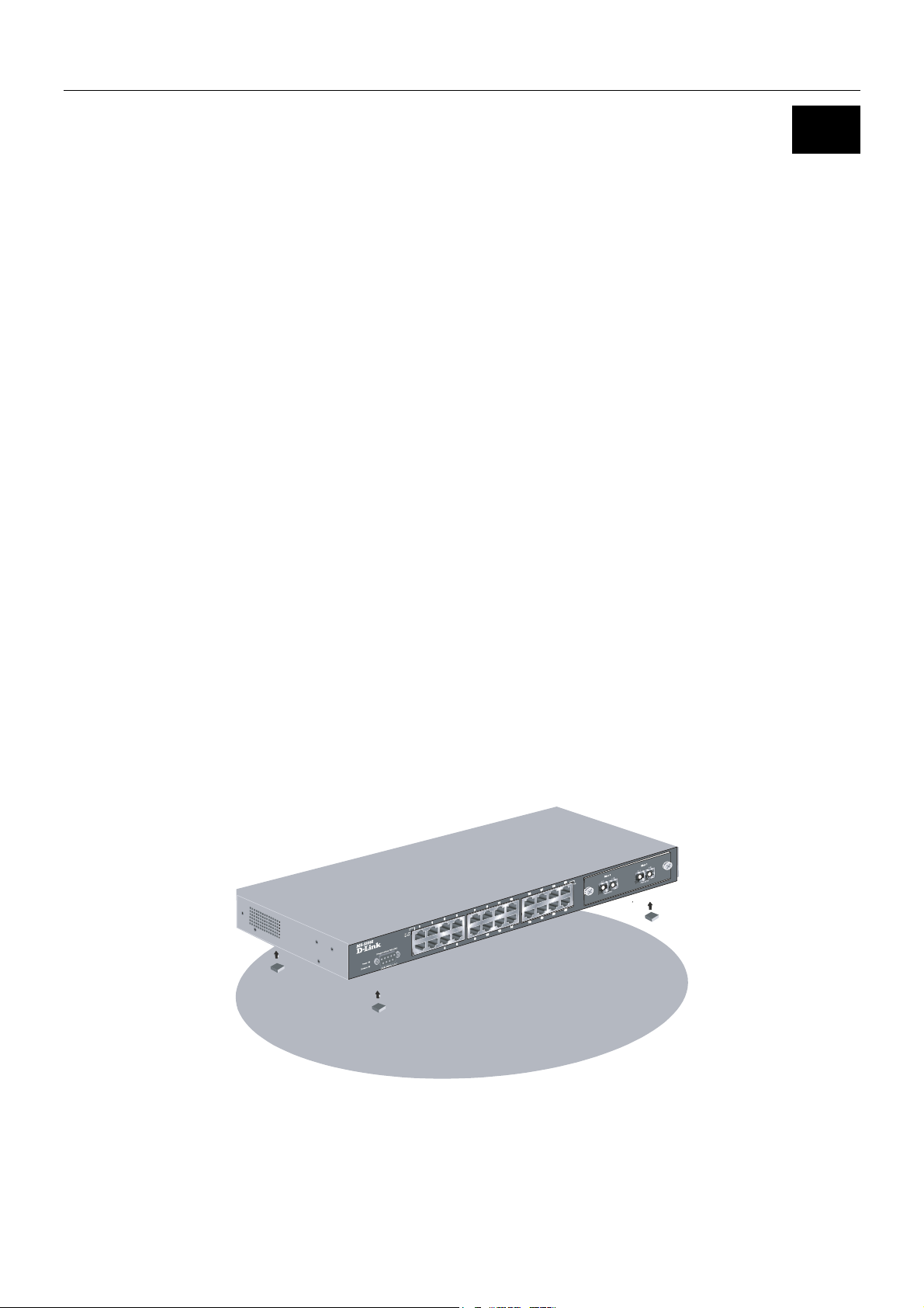
Desktop or Shelf Installation
When installing the Switch on a desktop or shelf, the rubber feet included with the device should first be attached. Attach these
cushioning feet on the bottom at each corner of the device. Allow adequate space for ventilation between the device and the
objects around it.
Figure 2-1. Installing rubber feet for desktop installation
3
Page 11
DES-3226S Layer 2 Fast Ethernet Switch User’s Guide
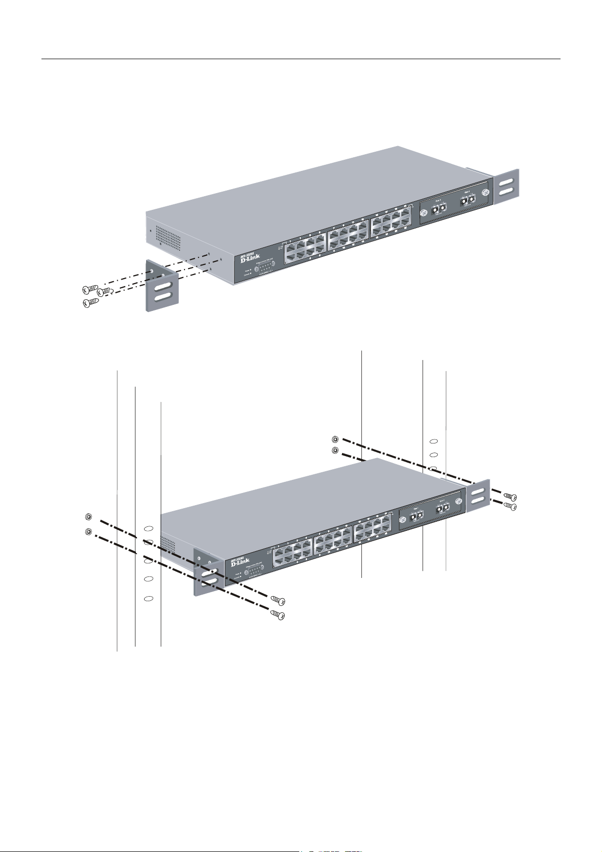
Rack Installation
The DES-3226S can be mounted in an EIA standard-sized, 19-inch rack, which can be placed in a wiring closet with other
equipment. To install, attach the mounting brackets on the Switch’s side panels (one on each side) and secure them with the
screws provided.
Figure 2- 2. Attaching the mounting brackets to the Switch
Then, use the screws provided with the equipment rack to mount the Switch on the rack.
Figure 2-3. Installing the Switch on an equipment rack
4
Page 12

DES-3226S Layer 2 Fast Ethernet Switch User’s Guide
Power on
The DES-3226S Switch can be used with AC power supply 100-240 VAC, 50 - 60 Hz. The power Switch is located at the rear
of the unit adjacent to the AC power connector and the system fan. The Switch’s power supply will adjust to the local power
source automatically and may be turned on without having any or all LAN segment cables connected.
After the power Switch is turned on, the LED indicators should respond as follows:
• All LED indicators will momentarily blink. This blinking of the LED indicators represents a reset of the system
The power LED indicator is always on after the power is turned ON
•
• The console LED indicator will blink while the Switch loads onboard software and performs a self-test. will remain ON if
there is a connection at the RS-232 port, otherwise this LED indicator is OFF
• The 100M LED indicator may remain ON or OFF depending on the transmission speed
Power Failure
As a precaution in the event of a power failure, unplug the Switch. When the power supply is restored, plug the Switch back
in.
5
Page 13
DES-3226S Layer 2 Fast Ethernet Switch User’s Guide
3
Identifying External Components
This chapter describes the front panel, rear panel, optional plug-in modules, and LED indicators of the DES-3226S.
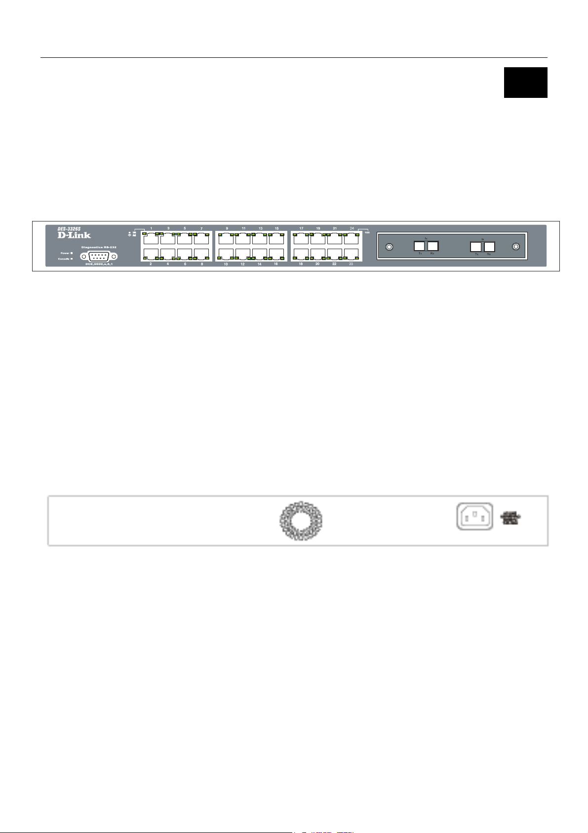
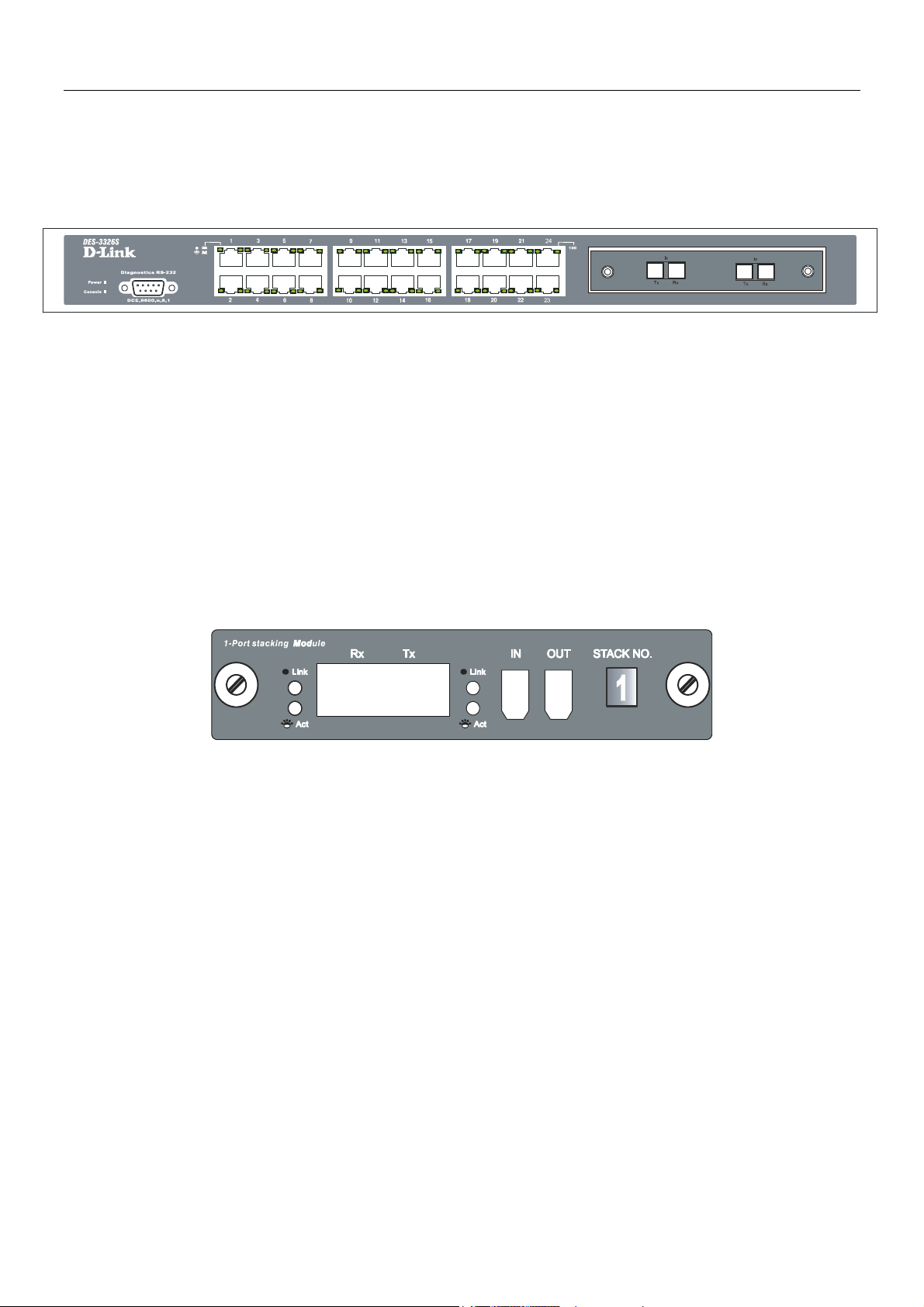
Front Panel
The front panel of the Switch consists of LED indicators, an RS-232 communication port, a slide-in module slot, and 24
(10/100 Mbps) Ethernet/Fast Ethernet ports.
Figure 3 - 1. Front panel view of the Switch
• Comprehensive LED indicators display the status of the Switch and the network (see the LED Indicators section below).
• An RS-232 DCE console port for setting up and managing the Switch via a connection to a console terminal or PC using a
terminal emulation program.
• A front-panel slide-in module slot for Gigabit Ethernet ports can accommodate a 2-port 1000BASE-T Gigabit Ethernet
module, a 2-port 1000BASE-SX Gigabit Ethernet module, a 2-port 1000BASE-LX Gigabit Ethernet module, or a 2-port
GBIC-based Gigabit Ethernet module.
• Twenty-four high-performance, NWay Ethernet ports all of which operate at 10/100 Mbps with Auto-MDIX function for
connections to end stations, servers and hubs. All ports can auto-negotiate between 10Mbps or 100Mbps, full or half
duplex, and flow control.
Rear Panel
The rear panel of the Switch contains an AC power connector.
Figure 3 - 2. Rear panel view of the Switch
The AC power connector is a standard three-pronged connector that supports the power cord. Plug-in the female connector of
the provided power cord into this socket, and the male side of the cord into a power outlet. Supported input voltages range
from 100 ~ 240 VAC at 50 ~ 60 Hz.
6
Page 14
DES-3226S Layer 2 Fast Ethernet Switch User’s Guide
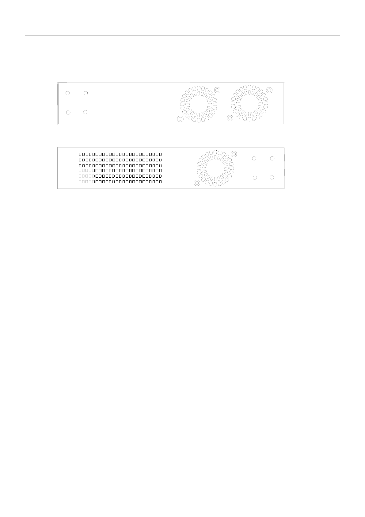
Side Panels
The right side panel of the Switch contains two system fans (see the top part of the diagram below). The left side panel
contains heat vents.
Figure 3 - 3. Side panel views of the Switch
The system fans are used to dissipate heat. The sides of the system also provide heat vents to serve the same purpose. Do not
block these openings, and leave at least 6 inches of space at the rear and sides of the Switch for proper ventilation. Be
reminded that without proper heat dissipation and air circulation, system components might overheat, which could lead to
system failure.
7
Page 15
DES-3226S Layer 2 Fast Ethernet Switch User’s Guide
Optional Plug-in Modules
The DES-3226S 24-port Fast Ethernet Switch is able to accommodate a range of optional plug-in modules in order to increase
functionality and performance. These modules must be purchased separately.
DES-132 2-port 100BASE-TX Module
Figure 3 - 4. 100BASE-TX two-port module
Port Functions
• Fully compliant with IEEE802.3 10BASE-T, IEEE802.3u 100BASE-TX
• Supports auto-negotiation in the following operation:
• 10/100M operation
• Full/Half Duplex operation
• Flow control: IEEE 802.3x compliant Flow Control support for full-duplex. Back pressure Flow Control support for
half-duplex mode.
LED Indicators
Speed
Link
Active
Off – 10M
Solid Green – 100M
Off – No Link
Solid Green – Link
Off – No Activity
Blinking Green – Activity
8
Page 16

DES-3226S Layer 2 Fast Ethernet Switch User’s Guide
DES-131F/132F 1/2-port 100BASE-FX Module
Figure 3 - 5. 100BASE-FX two-port module
Port Functions
• Fully compliant with IEEE802.3u 100BASE-FX
• Supports auto-negotiation in the following operation: 100M / Full-duplex / Flow control
• IEEE 802.3x compliant Flow Control support for full-duplex
Connector: SC Type
Distance: 2km
LED Indicators
Link
Active
Off – No Link
Solid Green – Link
Off – No Activity
Blinking Green – Activity
9
Page 17
DES-3226S Layer 2 Fast Ethernet Switch User’s Guide
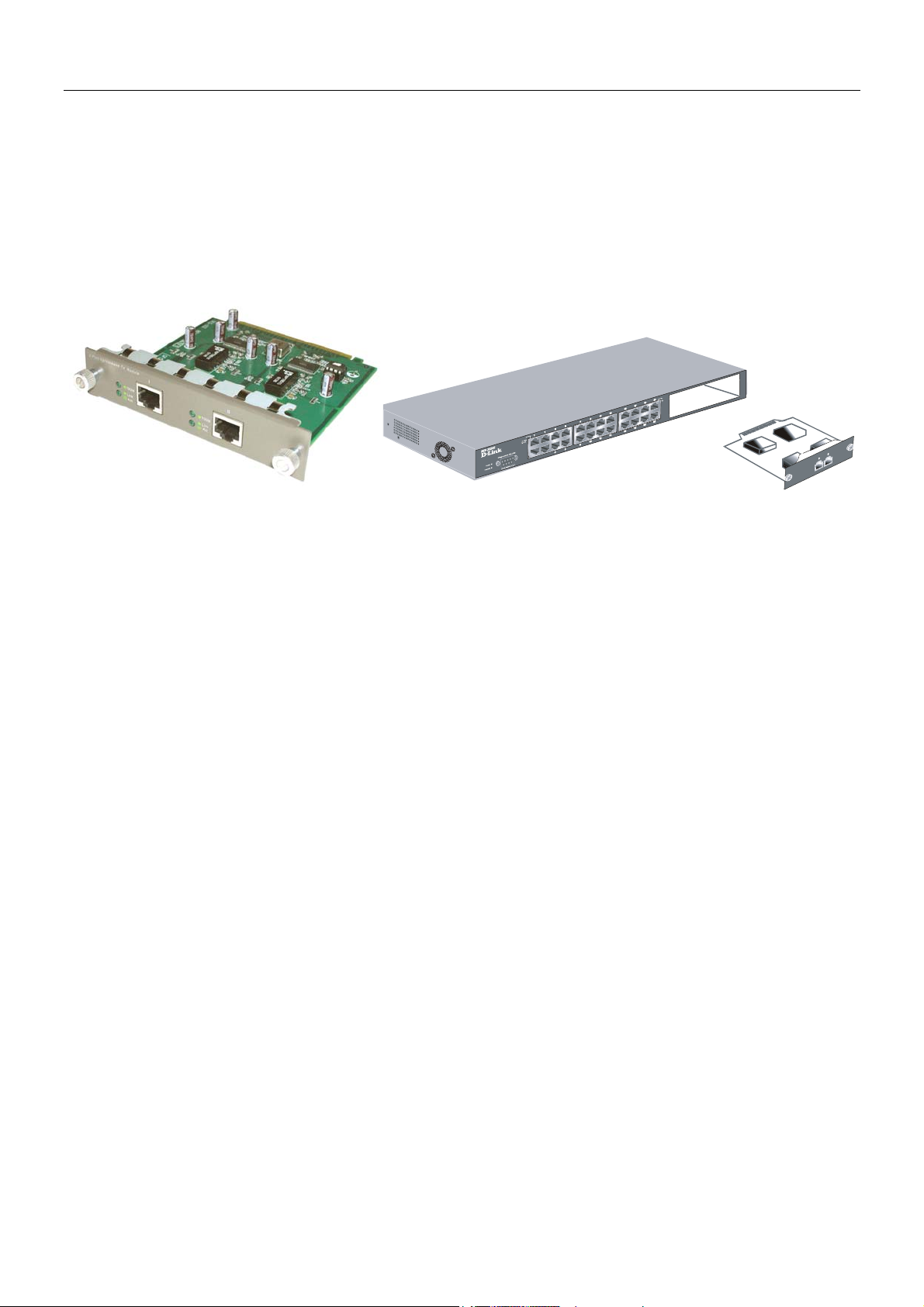
DES-131FL/132FL 1/2-port 100BASE-FX Module
Figure 3 - 6. 100BASE-FX module
Port Functions
• Fully compliant with IEEE802.3u 100BASE-FX
• Supports auto-negotiation in the following operation: 100M / Full-duplex / Flow control
• IEEE 802.3x compliant Flow Control support for full-duplex
Connector: SC type
Distance: 15km
LED Indicators
Link
Active
Off – No Link
Solid Green – Link
Off – No Activity
Blinking Green – Activity
10
Page 18

DES-3226S Layer 2 Fast Ethernet Switch User’s Guide
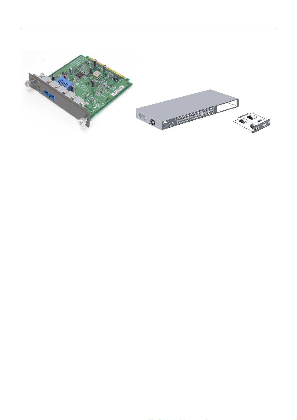
DES-132T 2-port 1000BASE-T Module
Figure 3 - 7. 1000BASE-T two-port module
Port Functions
• 2 1000BASE-T Gigabit Ethernet ports
• Fully compliant with IEEE802.3 10BASE-T, IEEE802.3u 100BASE-TX, and IEEE802.3ab 1000BASE-T
• Supports auto-negotiation in the following operation: 10/100/1000M / Full-duplex / Flow control
• IEEE 802.3x compliant Flow Control support for full-duplex
LED Indicators
Speed
(1000M)
Link
Active
Off – 10/100M
Solid Green – 1000M
Off – No Link
Solid Green – Link
Off – No Activity
Blinking Green – Activity
11
Page 19
DES-3226S Layer 2 Fast Ethernet Switch User’s Guide
DES-132G 2-port 1000BASE-SX Gigabit Ethernet Module
Figure 3 - 8. 1000BASE-SX two-port module
Port Functions
• 2 1000BASE-SX Gigabit Ethernet ports
• IEEE 802.3z 1000BASE-SX compliance
• Supports Full-duplex operations
• IEEE 802.3x compliant Flow Control support for full-duplex
Connector: SC Type
Distance: 550m
DEM-320S 2-port 1000BASE-SX Gigabit Ethernet Module
Port Functions
• 2 1000BASE-SX Gigabit Ethernet ports
• IEEE 802.3z 1000BASE-SX compliance
• Supports Full-duplex operations
• IEEE 802.3x compliant Flow Control support for full-duplex
Connector: SC Type
Distance: 550m
LED Indicators
Link
Active
Off – No Link
Solid Green – Link
Off – No Activity
Blinking Green – Activity
12
Page 20
DES-3226S Layer 2 Fast Ethernet Switch User’s Guide
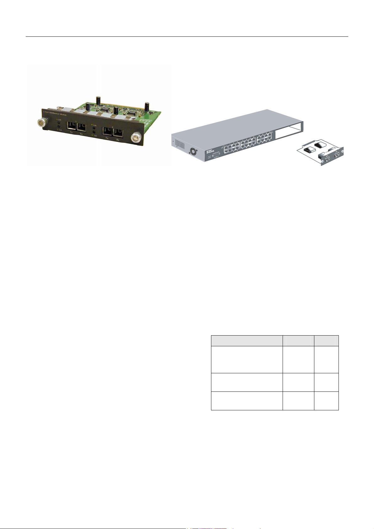
DES-132GL 2-port 1000BASE-LX Gigabit Ethernet Module
Figure 3 - 9. 1000BASE-LX two-port module
Port Functions
• 2 1000BASE-LX Gigabit Ethernet ports
• IEEE 802.3z 1000BASE-LX compliance
• Supports Full-duplex operations
• IEEE 802.3x compliant Flow Control support for full-duplex
• Supports multi-mode fiber optic cable connections of up to 550 meters or 5 km single-mode fiber-optic cable
connections.
Connector: SC Type
Distance: 5km
DEM-320L 2-port 1000BASE-LX Gigabit Ethernet Module
Port Functions
• 2 1000BASE-LX Gigabit Ethernet ports
• IEEE 802.3z 1000BASE-LX compliance
• Supports Full-duplex operations
• IEEE 802.3x compliant Flow Control support for full-duplex
• Supports single-mode fiber optic cable connections of up to 550 meters or 5 km single-mode fiber-optic cable
connections.
Connector: SC Type
Distance: 10km (9/125um)
LED Indicators
Link
Active
Off – No Link
Solid Green – Link
Off – No Activity
Blinking Green – Activity
The 1000BASE-SX module allows connections
using multi-mode fiber optic cable in the following
configurations:
Modal bandwidth
(min. overfilled launch)
Unit: MHz*km
Operating distance
Unit: meters
Channel insertion loss
Unit: dB
62.5µm 50µm
200 500
275 550
2.53 3.43
13
Page 21

DES-3226S Layer 2 Fast Ethernet Switch User’s Guide
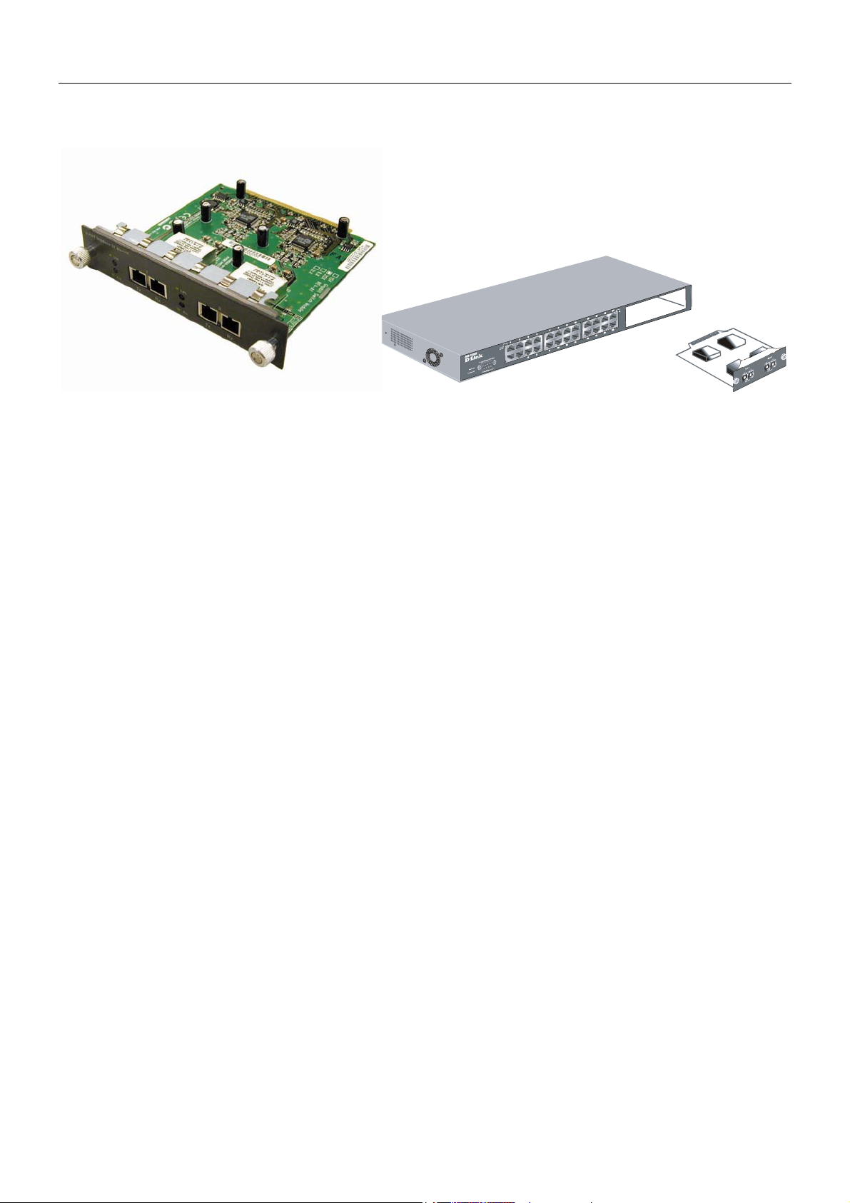
DES-132GB 2-port GBIC-based Gigabit Ethernet Module
Figure 3 - 10. GBIC two-port module
Port Functions
• 2 GBIC-based Gigabit Ethernet ports
• Allows multi-mode fiber optic connections of up to 550 m (SX and LX) and single-mode fiber optic connections of
up to 5 km (LX only). GBIC modules are available in –SX and –LX fiber optic media.
• IEEE 802.3z compliance
• Supports full-duplex operations
• IEEE 802.3x compliant Flow Control support for full-duplex
DEM-320GH 2-port GBIC-based Gigabit Ethernet Module
Port Functions
• 2 GBIC-based Gigabit Ethernet ports
• Allows multi-mode fiber optic connections of up to 550 m (SX and LX) and single-mode fiber optic connections of
up to 5 km (LX only). GBIC modules are available in –SX and –LX fiber optic media.
• IEEE 802.3z compliance
• Supports full-duplex operations
• IEEE 802.3x compliant Flow Control support for full-duplex
LED Indicators
Link
Active
Off – No Link
Solid Green – Link
Off – No Activity
Blinking Green – Activity
14
Page 22
DES-3226S Layer 2 Fast Ethernet Switch User’s Guide
t
r
d
a
r
d
p
f
f
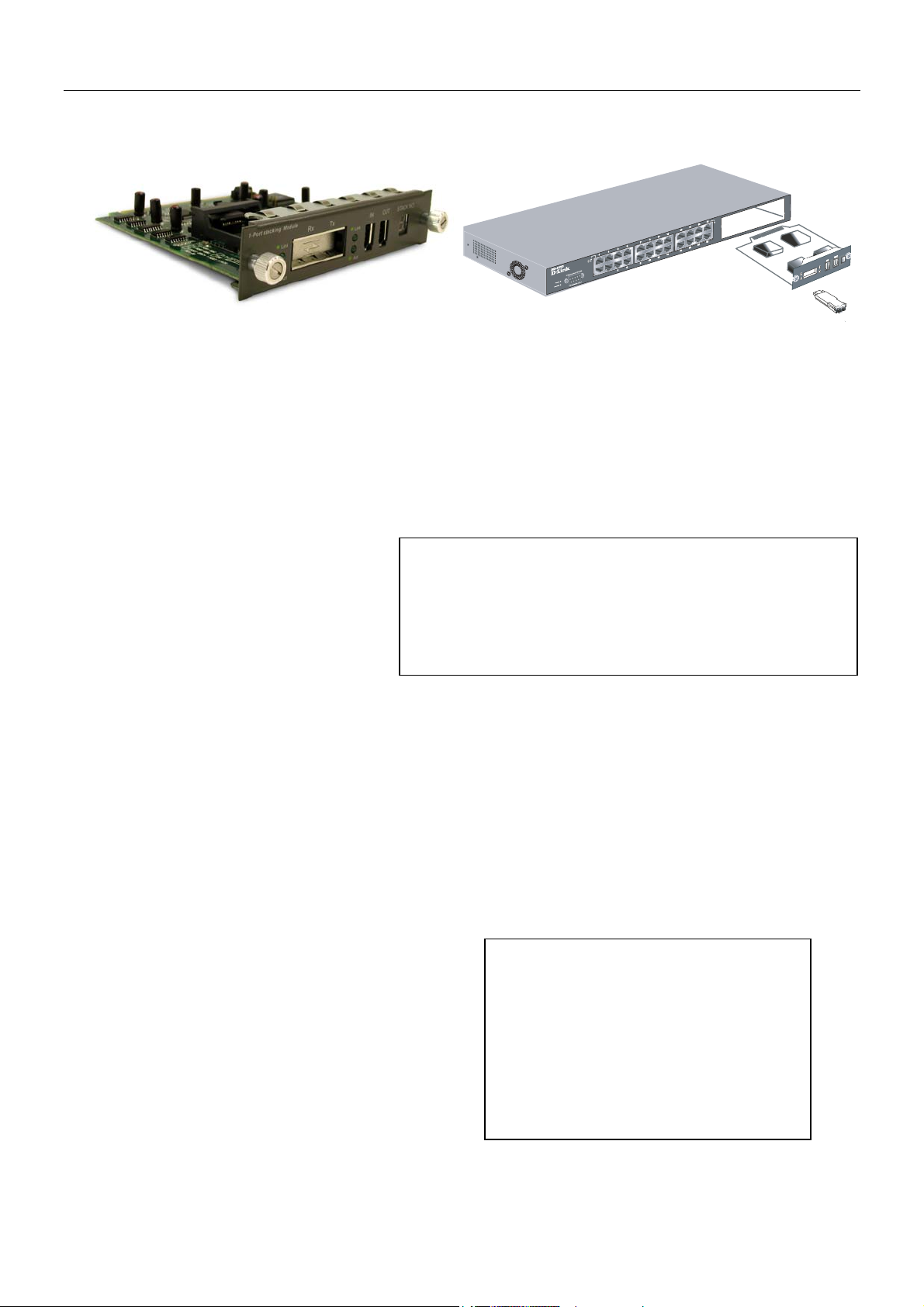
DES-332GS 1-port GBIC-Based Gigabit Ethernet Switch and stacking Module
Figure 3 - 11. Stacking Module with one GBIC port
Port Functions
• 1 GBIC-Based Gigabit Ethernet port
• Allows multi-mode fiber optic connections of up to 550 m (SX and LX) and single-mode fiber optic connections of
up to 5 km (LX only). GBIC modules are available in –SX and –LX fiber optic media.
• IEEE 802.3z 1000BASE-SX compliance
• Supports Full-duplex operations
• IEEE 802.3x compliant Flow Control support for full-duplex
Stacking Port Function
• 1 transmitting port and 1 receiving port
• IEEE1394.b compliance
• Forwarding rate up to 965Mbps
The stacking ports are marked IN and OUT. The IEEE 1394 compliant
cable must be connected from an IN port on one Switch to an OUT
the next Switch in the stack. The last two Switches (at the top and bottom o
the stack) must also be connected from the IN port on one Switch to the
OUT port on the other Switch. In this way, a loop is made such that all o
the Switches in the Switch stack have the IN stacking port connected to
another Switch’s OUT stacking port.
ort on
DEM-320GS 1-port GBIC-Based Gigabit Ethernet Switch and stacking Module
Port Functions
• 1 GBIC-Based Gigabit Ethernet port
• Allows multi-mode fiber optic connections of up to 550 m (SX and LX) and single-mode fiber optic connections of
up to 5 km (LX only). GBIC modules are available in –SX and –LX fiber optic media.
• IEEE 802.3z 1000BASE-SX compliance
• Supports Full-duplex operations
• IEEE 802.3x compliant Flow Control support for full-duplex
Stacking Port Function
• 1 transmitting port and 1 receiving port
• IEEE1394.b compliance
• Forwarding rate up to 965Mbps
LED Indicators
Link
Active
Off – No Link
Solid Green – Link
Off – No Activity
Blinking Green – Activity
The optional Stacking Module allows up to eigh
DES-3226S Switches to be interconnected via thei
individual stacking modules. This forms an eightSwitch stack that can then be managed an
configured as thought the entire stack were a single
Switch. The Switch stack is then accessed through
single IP address or alternatively, through the maste
Switch’s serial port (via the management station’s
console and the Switch’s Command Line Interface).
The stacking module’s LED indicators are describe
below.
15
Page 23
DES-3226S Layer 2 Fast Ethernet Switch User’s Guide
LED Indicators
The LED indicators of the Switch include Power, Console, and Link/Act. The following shows the LED indicators for the
Switch along with an explanation of each indicator.
Figure 3 - 12. The LED Indicators
• Power This indicator on the front panel should be lit during the Power-On Self Test (POST). It will light green
approximately 2 seconds after the Switch is powered on to indicate the ready state of the device.
• Console This indicator is lit green when the Switch is being managed via out-of-band/local console management
through the RS-232 console port using a straight-through serial cable.
• Act/Link/Speed These indicators are located to the left and right of each port. The right side indicator will light
when the port has a link of 100 Mbps; the Link indicator will not light for 10 Mbps links. The LEDs blink whenever
there is reception or transmission (i.e. Activity--Act) of data occurring at a port.
Stacking Module LED Indicators
The Switch’s current order in the Switch stack is also displayed on the Stacking Module’s front panel − under the STACK
NO. heading:
Figure 3 - 13. Stacking Module LED Indicators
The Link and Act LEDs have the same function as the corresponding LEDs for the Switch’s Ethernet ports. The Link LED
lights to confirm a valid link, while the ACT LED blinks to indicate activity on the link.
The Stack No. seven-segment LED displays the unit number assigned to the Switch. The numeral 1 in the display indicates
that the stacking module is in the process of determining the stack status and has not yet resolved the Switch’s unit number.
If the master Switch fails, a new master Switch should be configured for the stack until the failure can be fixed. Any time the
composition of a stacked Switch group changes, all Switches in the stack will reboot automatically and the master-slave
relationship and stack number will be renegotiated. A link failure will require reconnecting the stacking ports to work around
the failed link.
16
Page 24
DES-3226S Layer 2 Fast Ethernet Switch User’s Guide
4
Connecting the Switch
This chapter describes how to connect the DES-3226S to your Fast Ethernet network.
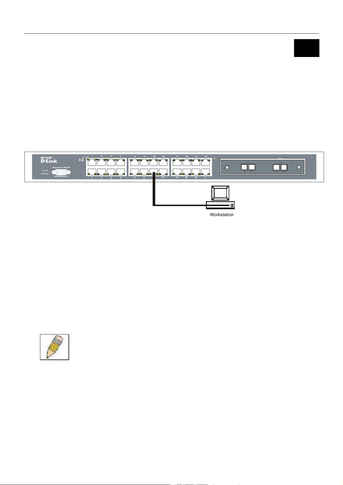
Switch to End Node
End nodes include PCs outfitted with a 10, 100 or 10/100 Mbps RJ-45 Ethernet/Fast Ethernet Network Interface Card (NIC)
and most routers.
An end node can be connected to the Switch via a two-pair Category 3, 4, 5 UTP/STP straight cable (be sure to use Category 5
UTP or STP cabling for 100 Mbps Fast Ethernet connections. Connections to 1000 Mbps Gigabit ports on the 1000BASE-T
Module must also use Category 5e). The end node should be connected to any of the twenty-four ports of the DES-3226S.
Figure 4 - 1. Switch connected to an End Node
The LED indicators for the port the end node is connected to are lit according to the capabilities of the NIC. If LED indicators
are not illuminated after making a proper connection, check the PC’s LAN card, the cable, Switch conditions, and connections.
The following LED indicator states are possible for an end node to Switch connection:
• The 100 LED indicator comes ON for a 100 Mbps and stays OFF for 10 Mbps.
• The Link/Act LED indicator lights up upon hooking up a PC that is powered on.
Switch to Hub or Switch
These connections can be accomplished at any port in either straight-through cable or a crossover cable because the Switch
supports Auto-MDIX function.
NOTE: Auto-MDIX function is not supported by the 100BASE-TX module.
• A 10BASE-T hub or Switch can be connected to the Switch via a two-pair Category 3, 4 or 5 UTP/STP cable.
• A 100BASE-TX hub or Switch can be connected to the Switch via a two-pair Category 5 UTP cable.
• A 1000BASE-T connections use two-pair Category 5e UTP cable.
17
Page 25
DES-3226S Layer 2 Fast Ethernet Switch User’s Guide
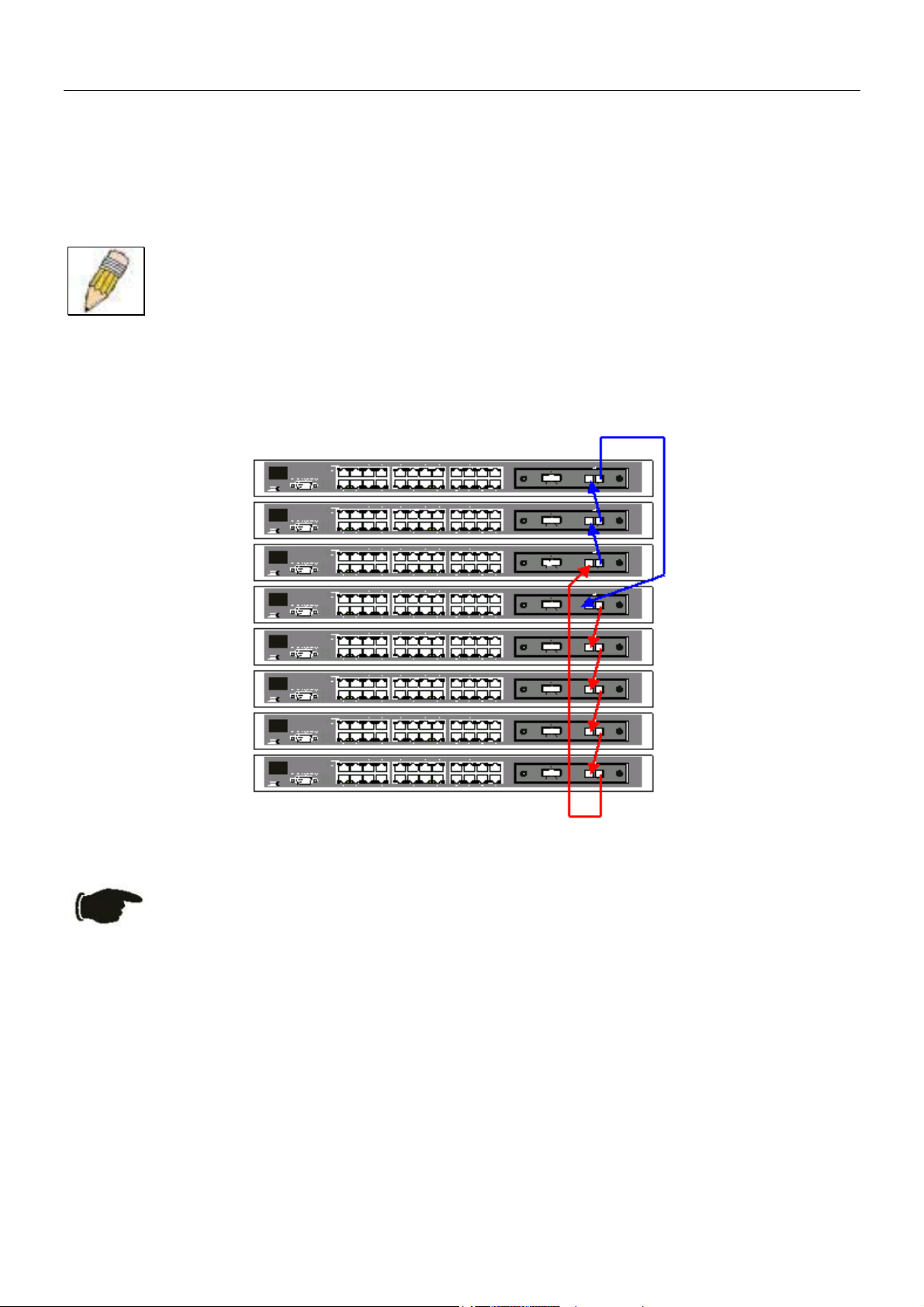
Switch Stack Connections
Up to eight DES-3226S Switches (with optional stacking modules installed) can be stacked into a Switch stack that can then be
configured and managed as a single unit. The management agent of the master Switch can configure and manage all of the
Switches in a Switch stack − using a single IP address (the IP address of the Master Switch).
NOTE: Stacking mode is configured using the CLI command config stacking mode. The default
settings allow the Switch to function as a standalone device or as a member of a stacked group.
The stacking ports are marked IN and OUT. The IEEE 1394 compliant cable must be connected from an IN port on one
Switch to an OUT port on the next Switch in the stack. The last two Switches (at the top and bottom of the stack) must also be
connected from the IN port on one Switch to the OUT port on the other Switch. In this way, a loop is made such that all of the
Switches in the Switch stack have the IN stacking port connected to another Switch’s OUT stacking port.
An example stacking port interconnection is shown below:
Figure 4 - 2. Switch Stack connections between optional stacking modules
NOTICE: If a link between stacked Switches fails the stacked group must be connected to work
around the failed link. As with any changes in the composition of the stacked Switch group, the new
stacking relationship must be negotiated. Any change to the composition of a stacked Switch group
or any failure of a stacking port will cause the entire stack to restart and negotiate the new stacking
composition.
10BASE-T Device
For a 10BASE-T device, the Switch’s LED indicators should display the following:
• 100 LED speed indicator is OFF.
• Link/Act indicator is ON.
100BASE-TX Device
For a 100BASE-TX device, the Switch’s LED indicators should display the following:
• 100 LED speed indicator is ON.
• Link/Act is ON.
18
Page 26

DES-3226S Layer 2 Fast Ethernet Switch User’s Guide
5
Management Concepts
This chapter discusses many of the concepts and features used to manage the Switch, as well as the concepts necessary for the
user to understand the functioning of the Switch. Further, this chapter explains many important points regarding these features.
Configuring the Switch to implement these concepts and make use of its many features is discussed in detail in the next
chapters.
Local Console Management
A local console is a terminal or a workstation running a terminal emulation program that is connected directly to the Switch via
the RS-232 serial console port on the front of the Switch. A console connection is referred to as an ‘Out-of-Band’ connection,
meaning that console is connected to the Switch using a different circuit than that used for normal network communications.
So, the console can be used to set up and manage the Switch even if the network is down.
Local console management uses the terminal connection to operate the console program built-in to the Switch. A network
administrator can manage, control and monitor the Switch from the console program.
The DES-3226S contains a CPU, memory for data storage, flash memory for configuration data, operational programs, and
SNMP agent firmware. These components allow the Switch to be actively managed and monitored from either the console
port or the network itself (out-of-band, or in-band).
Diagnostic (console) port (RS-232 DCE)
Out-of-band management requires connecting a terminal, such as a VT-100 or a PC running a terminal emulation program
(such as HyperTerminal, which is automatically installed with Microsoft Windows) a to the RS-232 DCE console port of the
Switch. Switch management using the RS-232 DCE console port is called Local Console Management to differentiate it from
management performed via management platforms, such as D-View, HP OpenView, etc. Web-based Management describes
management of the Switch performed over the network (in-band) using the Switch’s built-in Web-based management program
(see Chapter 6 – Web-based Network Management). The operations to be performed and the facilities provided by these two
built-in programs are identical.
The console port is set at the factory for the following configuration:
• Baud rate: 9,600
• Data width: 8 bits
• Parity: none
• Stop bits: 1
• Flow Control None
Make sure the terminal or PC you are using to make this connection is configured to match these settings.
If you are having problems making this connection on a PC, make sure the emulation is set to VT-100. If you still don’t see
anything, try pressing <Ctrl> + r to refresh the screen.
19
Page 27

DES-3226S Layer 2 Fast Ethernet Switch User’s Guide
Stacking vs. Standalone Operation (Release 4.01)
By default, the Switch configuration settings allow it to operate as a standalone device, or in a stacked group. It is not
necessary to change any settings for the Switch to function in either capacity. However, it is useful to understand how the
stacking mode operates in the Switch and the effects if any this may have on configuration settings in a Switch when its
stacking status is changed.
Stacking mode is enabled by default and can be changed using the CLI command config stacking mode. If the Switch
has stacking mode enabled and is properly connected to other DES-3226S Switches, a negotiation takes place upon starting up
the Switches to determine how the Switch functions in the stack. For an all-DES-3226S stack, any time a change occurs in the
structure or composition of a stacked Switch group the entire stack will restart and the negotiation process begins anew. When
the stacking mode is disabled (config stacking mode disable), the Switch only allows standalone operation. If
stacking mode is disabled on a Switch, it should be disconnected from a stacked group.
NOTE: The firmware for Release 4.01 allows stacking operation of the DES-3226S as a slave to the
DGS-3212SR and DGS-3312SR in a star topology. See the example below for more information.
Stacking mode can be changed using the CLI. When a DES-3226S Switch stack is first assembled, it is advisable to determine
which Switch will function as the master before placing the Switches in a rack and connecting them. If the Switch is used in a
stacked group with the DGS-3212SR or DGS-3312SR, the DGS-3x12SR series Switch operates as the master and the DES3226S Switches in the stacked group operate as slaves. The possible stacking configuration modes are as follows:
Enabled: Stacking mode is enabled by default. When enabled the Switch can operate as a standalone device or it can operate
with other DES-3226S Switches in a properly connected stacked group. Stacking must be enabled for the Switch function in a
stacked arrangement with other DES-3226S Switches or with a DGS-3212SR High-Density Layer 2 or DGS-3312SR Layer 3
Gigabit Ethernet Switch.
Auto: This is the default stacking mode setting for the DES-3226S. In auto stacking mode the Switch is eligible for stacking or
it can operate as a standalone device. If a DES-3226S Switch stack is connected and all units are configured to operate in auto
stacking mode, the master-slave relationships is determined automatically. For DES-3226S Switch stacks, the unit with the
lowest MAC address becomes the master (stack number 1). The order in which slave devices appear logically in the stack
(stack number 2+) is determined by how they are connected relative to the master Switch. The auto mode serves to first
determine if the device is stacked or standalone, then if stacked, it determines which Switch is the master and the remaining
stack numbers for the slave Switches.
Master: The auto mode described above may be overridden so that a properly connected Switch in a stack may be forced into
master mode. Only one Switch in a stack may act as the master and all configuration settings for the stacked group - including
stacking configuration - are saved in configuration files in the master Switch. The stack is managed as a single entity through
the master. It may be convenient to place the master unit in the upper-most slot of a stacked group to visually distinguish it
form the slave units. The master unit should be used to uplink the stack group to the backbone. If the master unit fails or is
replaced for any reason, it is possible to load configuration files saved from the original master unit in order to continue
operation with identical settings. See the example below for a description of how to swap the master unit of a stacked group. A
Switch configured as the stack master will maintain this status regardless of any changes that occur in the composition of the
stacked group. If for example a connection to a slave unit or a connection between two slave units were to fail, the entire stack
will restart automatically. After restarting, the designated master unit retains its status.
Slave: The auto mode may be overridden to force the Switch to operate in slave mode. When the Switch is in slave mode, it is
ineligible to function as a master and all configuration, is done through the master unit. A master Switch must be properly
connected to the stack for a Switch to operate in slave mode.
Disabled: This forces the Switch to operate as a standalone device. In standalone mode the Switch functions as a standalone
device even if a stacking module is installed. To force standalone operation it is necessary to use the CLI command
config stacking mode disable. A Switch that has stacking mode disabled should never connect to another Switch
through stacking ports.
NOTICE: Do not use stacking ports on a Switch that has the stacking mode disabled.
20
Page 28

DES-3226S Layer 2 Fast Ethernet Switch User’s Guide
For DES-3226S Switch stacks, changes made to the composition of a Switch stack group, that is, adding new Switches or
taking Switches out of the stack, require all Switches to restart. The new stacking order is negotiated to reflect the changes
made to the group. If the master Switch has been configured to force master status it retains this status, likewise Switches
forced to operate in slave mode retain the status after restarting. The restart occurs automatically if any stacking link is
disconnected.
For star topology arrangements, the DGS-3212SR or DGS-3312SR does not restart when a link or Switch failure occurs. Only
the effected Switch will restart if its link to the DGS-3x12SR series Switch fails. The remaining DES-3226S Switches continue
to operate as before.
The command show stacking can be used to view stacking information. If stacking has been disabled, the stacking mode will
be listed as Standalone.
Managing Switch Stacks
Multiple DES-3226S Switches equipped with stacking modules may be connected in a stacking arrangement so that up to eight
Switches are managed as a single unit with a single IP address. The Release 4.01 DES-3226S can connect to the DGS-3212SR
or DGS-3312SR via the stacking port in a star topology. Up to eight Switches may be connected to the DGS-3x12SR and be
managed as a slave device through the DGS-3x12SR series Switch.
The default stacking mode will establish a master Switch for the stack through a negotiation process that takes place when all
devices are started up. In a DES-3226S stack, the Switches negotiate the master-slave relationship. Once the master Switch is
determined, the remaining Switches function as slaves. The stack number of the slave Switches is determined by where it is
actually positioned in the stack. This can be taken into account when you are placing the Switches in an equipment rack.
For star topology stacking arrangements with the DGS-3212SR or DGS-3312SR, the default settings of the DES-3226S assign
slave status and the unit number is determined by the number of the port connected at the other end of the stacking connection.
Keep in mind the following important considerations for stacked Switch groups:
• All management of the Switches in the stack is done through the master Switch.
• The master Switch should be used to uplink to the Ethernet backbone.
• For DES-3226S stacks, the master Switch can be chosen automatically as each Switch in a connected stack competes
for status. However, you can choose a specific device and force it to operate as the master. Use the CLI command
config stacking mode enabled master for the selected Switch; leave the remaining Switches in the
default auto-stacking mode.
• For DES-3226S stacks, if the link between any two Switches fails or is disconnected, or if any Switch in a stacked
group fails, all of the Switches in the stack will automatically reboot. Since the stack is connected as a ring, the stack
will need to be connected to work around the failed link. Change the cabling to bypass the failed link and allow the
stack to reboot. The Switches will negotiate again since the composition of the stack has been altered. Read below for
more information about changes in stacked Switch groups.
• A Switch stack has a single IP address − if the stacking link to a given Switch fails or is disconnected, that Switch will
loose its status in the stack and reboot as a standalone device with the IP settings it had before becoming a member of
the Switch stack.
NOTE: For Release 4.01 the DES-3226S maintains two separate configurations, one for standalone
operation and another for stacked operation. Each configuration has identical IP settings, VLANs, link
aggregation, QoS, etc. This dual system allows a Switch to change status from standalone to stacking
enabled and keep its configuration settings.
Changes to Switch Stack Structure
If Switches are added to or taken out of a stacked group of DES-3226S Switches it is necessary to change the composition of a
Switch stack and rearrange the stacking connections. If a stacking link fails or if a member of a stacked group fails, the
composition of the stack will necessarily change also. In such a case intervention is required to at least reconnect the stacking
cable to bypass the failure. In addition to making changes to the cable links connecting the Switches in the stack, it may be
necessary or desirable to change the stacking mode configuration of one or more units. A few examples presented below to
help make the changes to cable connections for DES-3226S stacks and if necessary, to Switch stacking mode configuration
settings.
21
Page 29
DES-3226S Layer 2 Fast Ethernet Switch User’s Guide
NOTE: For a Switch that has already been configured with many settings already in place, it is a good
idea to save the configuration files to a server before changing the stacking mode status.
Configuration files can be saved using the CLI, SNMP manager or web manager interface.
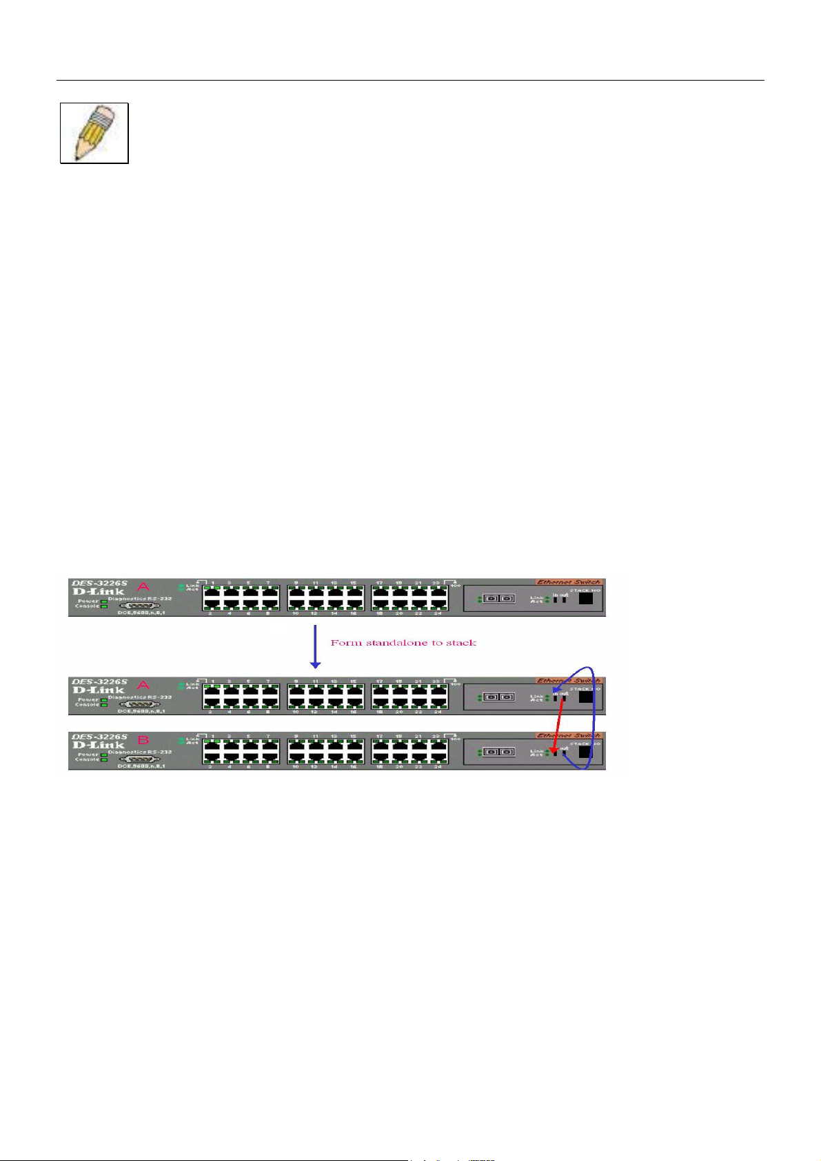
Convert a Standalone Switch to a Stacked Switch
A Switch that has previously acted in a standalone capacity may become a member of a stacked group simply by installing a
stacking module and connecting it to a connected Switch stack. For this example, let’s assume Switch A has been setup as a
standalone device and has been functioning on the network. We want to join this Switch with another DES-3226S, Switch B,
to form a 2-Switch stack. Many configuration settings including IP settings have already been set on Switch A so we will keep
these and use them for the new stacked arrangement. Switch A is also uplinked to the backbone via the GBIC port in the
stacking module. Switch A will stay in its position in the uppermost slot in the rack and all network connections will remain in
place.
First, save the configuration files to a TFTP server so they may be reloaded if any problems occur. This should be done
whether or not stacking mode is changed.
Since we want to keep the same IP address and all the other setting on the standalone Switch, this Switch will become the
master of the stack and Switch B will be the slave. To make sure Switch A functions as the master we will enable stacking and
override the auto function.
Use the CLI to enter the command: config stacking mode enable master
The stacking mode for Switch B is set to the default auto-stacking mode and therefore no changes are required. Switch B will
lose configuration settings including its IP settings, so if you want to save these be sure to upload the configuration files before
making the stacking connection.
Power off both devices and place Switch B under Switch A in the rack. It is not actually required that the slave device be
placed under the master in the stack but it may be easier so that the master Switch may be instantly recognized. This may prove
especially convenient where multiple Switch stacks are installed so it is always clear which unit should be used to uplink.
Both Switches are now powered off. Switch B is placed securely in the rack and connected to Switch A via the stacking ports.
Both devices are powered on; they recognize the stacking connection and begin negotiating the stacking relationship. Switch A
is configured to function as the master device. Switch B automatically assume slave status. Switch A will keep its IP settings
and its other configurations remain unchanged. The stack may now be configured as a single entity.
Add a Switch to a Stack
Adding a new slave device to a Switch stack is a simple procedure. If you are swapping an existing Switch, label each Ethernet
cable attached to the device being swapped so they can be placed in the same port number in the replacement device.
To add a new slave to a stack, place the new unit in the next available slot below the stack. Power off all Switches in the stack
and make the necessary changes to the stacking cable connections. Use the illustrations below as a guide.
22
Page 30
DES-3226S Layer 2 Fast Ethernet Switch User’s Guide
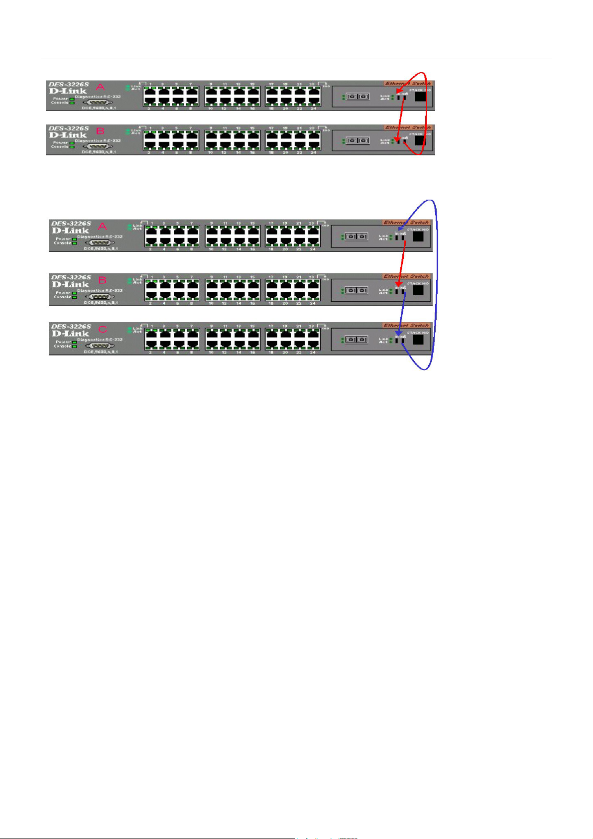
Switch C is added to the existing stack where Switch A is the designated master. Power off all devices and securely place
Switch C in the slot beneath Switch B. Adjust stacking cable connections so the OUT port on Switch B connects the IN port on
Switch C and the OUT port of Switch C connects to the IN port of Switch A.
Power on the entire stack. The new stacking arrangement is recognized and the new relationship is negotiated. Switch A retains
status as the master of the stack, Switch C is in auto mode and therefore functions as a slave. The stack is ready for operation.
Swap a Master from a Stack
Let’s assume the stack arrangement in the previous example has a problem that requires the master unit, Switch A, to be
replaced. In this case, we can preserve all the same configuration settings by downloading the previously saved configuration
files to the replacement Switch.
Before disconnecting the network connections of the original master unit, label each Ethernet cable so they can be placed in the
same port number in the replacement Switch. Then remove the device from the rack.
Place the replacement Switch in the same slot. Power on the new Switch and attach a console cable to it. Configure the new
unit to be a master and save the settings. Connect the Ethernet cable needed to access the TFTP server containing the saved
configuration files of the previous master unit. Download the saved configuration files, use the command:
download configuration <ipaddr> <path_filename>
Save the new settings and power off the Switch. Now the stacking connections and Ethernet connections can be completed
exactly as before. Reconnect the stacking cables and Ethernet connections and power on the entire stack. The stack should now
function as before with all the configuration settings intact.
23
Page 31

DES-3226S Layer 2 Fast Ethernet Switch User’s Guide
Stacking with DGS-3212SR or DGS-3312SR
The DES-3226S Release 4.01 Switch can be arranged in a star topology and managed as slave devices through either the DGS3212SR or DGS-3312SR Master Switch. Up to eight Switches can be connected to the DGS-3x12SR series Switch in this
arrangement.
Figure 5 - 1. DES-3226S Switches with DGS-3212SR
Setting up a star topology with a DGS-3212SR or DGS-3312SR is a simple matter. Each DES-3226S connects to the master
through the stacking port to a similar stacking port on a DGS-3x12SR series Switch equipped with one or two special stacking
modules designed for the DGS-3x12SR series Switch. Each DES-3226S slave must be configured with stacking mode enabled.
When stacked in a star topology arrangement with the DGS-3x12SR, the Switch will automatically assume slave status. The
unit number is determined by the port number to which it is connected on the DGS-3x12SR master. The DGS-3x12SR must
have a stacking module installed and have stacking mode enabled as well. Stacking for the DGS-3x12SR uses the identical
CLI command: config stacking mode enable. Be sure to save the configuration change using the CLI command
save.
Remember that for star topology arrangements, if the stacking link to a given Switch fails or is disconnected, that Switch will
loose its status in the stack and reboot as a standalone device with the IP settings. The DGS-3212SR/DGS-3312SR and
remaining slave units are not effected by the link failure.
NOTE: The DES-3226S must have stacking mode enabled to be used with the DGS-3212SR or the
DGS-3312SR in a star topology arrangement.
24
Page 32

DES-3226S Layer 2 Fast Ethernet Switch User’s Guide
Switch IP Address
Each Switch must be assigned its own IP Address, which is used for communication with an SNMP network manager or other
TCP/IP application (for example BOOTP, TFTP). The Switch’s default IP address is 10.90.90.90. You can change the default
Switch IP Address to meet the specification of your networking address scheme.
The Switch is also assigned a unique MAC address by the factory. This MAC address cannot be changed, and can be found
from the initial boot console screen – shown below.
Figure 5 - 2. Console Boot Screen
The Switch’s MAC address can also be found from the console program under the Switch Information menu item, as shown
below.
Setting an IP Address
The IP address for the Switch must be set before it can be managed with the web-based manager. The Switch IP address may
be automatically set using BOOTP or DHCP protocols, in which case the actual address assigned to the Switch must be
known.
The IP address may alternatively be set using the Command Line Interface (CLI) over the console serial port as follows:
1. Starting at the command line prompt DES3226S4# − enter the commands config ipif System ipaddress
xxx.xxx.xxx.xxx/yyy.yyy.yyy.yyy. Where the x’s represent the IP address to be assigned to the IP
interface named System and the y’s represent the corresponding subnet mask.
2. Alternatively, you can enter DES3226S4# − enter the commands config ipif system ipaddress
xxx.xxx.xxx.xxx/z. Where the x’s represent the IP address to be assigned to the IP interface named System
and the z represents the corresponding number of subnets in CIDR notation.
Using this method, the Switch can be assigned an IP address and subnet mask which can then be used to connect a
management station to the Switch’s web-based management agent.
25
Page 33

DES-3226S Layer 2 Fast Ethernet Switch User’s Guide
SNMP Network Management
The Simple Network Management Protocol (SNMP) is an OSI layer 7 (the application layer) protocol for remotely monitoring
and configuring network devices. SNMP enables network management stations to read and modify the settings of gateways,
routers, Switches, and other network devices. SNMP can be used to perform many of the same functions as a directly
connected console, or can be used within an integrated network management software package such as DView.
SNMP performs the following functions:
• Sending and receiving SNMP packets through the IP protocol.
• Collecting information about the status and current configuration of network devices.
• Modifying the configuration of network devices.
The DES-3226S has a software program called an ‘agent’ that processes SNMP requests, but the user program that makes the
requests and collects the responses runs on a management station (a designated computer on the network). The SNMP agent
and the user program both use the UDP/IP protocol to exchange packets.
SNMP Versions 1, 2 and 3
The DES-3226S supports SNMP version 3 as well as versions 1 and 2. The chief difference between Version 3 (SNMP v.3)
and Versions 1 and 2 (SNMP v.1 and SNMP v.2) is that it provides a substantially higher level of security than the previous
versions.
In SNMP v. and v.2, user authentication is accomplished using ‘community strings’, which function like passwords. The
remote user SNMP application and the router SNMP must use the same community string. SNMP packets from any station
that has not been authenticated are ignored (dropped).
SNMP v.3 uses a more sophisticated authentication process that is separated into two parts. One part is to maintain a list of
users and their attributes that are allowed to act as SNMP managers. The second part describes what each user on that list can
do as an SNMP manager.
The Switch allows groups of users to be listed and configured with a shared set of privileges. The SNMP version may also be
set for a listed group of SNMP managers. Thus, you may create a group of SNMP managers that are allowed to view read-only
information or receive traps using SNMP v.1 while assigning a higher level of security to another group, granting read/write
privileges using SNMP v.3.
Using SNMP v.3 individual users or groups of SNMP managers can be allowed to perform or be restricted from performing
specific SNMP management functions. The functions allowed or restricted are defined using the Object Identifier (OID)
associated with a specific MIB.
An additional layer of security is available for SNMP v.3 in that SNMP messages may be encrypted (using HMAC-SHA-96 or
HMAC-MDA-96 authentication levels).
Traps
Traps are messages that alert network personnel of events that occur on the Switch. The events can be as serious as a reboot
(someone accidentally turned OFF the Switch), or less serious like a port status change. The Switch generates traps and sends
them to the trap recipient (or network manager).
Trap recipients are special users of the network who are given certain rights and access in overseeing the maintenance of the
network. Trap recipients will receive traps sent from the Switch; they must immediately take certain actions to avoid future
failure or breakdown of the network.
You can also specify which network managers may receive traps from the Switch. This can be done by entering a list of the IP
addresses of authorized network managers. You may further specify the SNMP version to use for authentication. Up to four
trap recipient IP addresses, and four corresponding SNMP community strings can be entered.
The following are trap types the Switch can send to a trap recipient:
• Cold Start This trap signifies that the Switch has been powered up and initialized such that software settings are
reconfigured and hardware systems are rebooted. A cold start is different from a factory reset in that configuration
settings saved to non-volatile RAM used to reconfigure the Switch.
• Warm Start This trap signifies that the Switch has been rebooted, however the POST (Power On Self-Test) is
skipped.
• Authentication Failure This trap signifies that someone has tried to logon to the Switch using an invalid SNMP
community string. The Switch automatically stores the source IP address of the unauthorized user.
26
Page 34

DES-3226S Layer 2 Fast Ethernet Switch User’s Guide
• Topology Change A Topology Change trap is sent by the Switch when any of its configured ports transitions from
the Learning state to the Forwarding state, or from the Forwarding state to the Blocking state. The trap is not sent if a
new root trap is sent for the same transition.
• Link Change Event This trap is sent whenever the link of a port changes from link up to link down or from link down
to link up.
• Port Partition This trap is sent whenever the port state enters the partition mode (or automatic partitioning, port
disable) when more than thirty-two collisions occur while transmitting at 10Mbps or more than sixty-four collisions
occur while transmitting at 100Mbps.
• Broadcast\Multicast Storm This trap is sent whenever the port reaches the threshold (in packets per second) set
globally for the Switch. Counters are maintained for each port, and separate counters are maintained for broadcast
and multicast packets. The Switch’s default setting is 128 kpps for both broadcast and multicast packets.
MIBs
Management and counter information are stored in the Switch in the Management Information Base (MIB). The Switch uses
the standard MIB-II Management Information Base module. Consequently, values for MIB objects can be retrieved from any
SNMP-based network management software. In addition to the standard MIB-II, the Switch also supports its own proprietary
enterprise MIB as an extended Management Information Base. These MIBs may also be retrieved by specifying the MIB’s
Object-Identifier (OID) at the network manager. MIB values can be either read-only or read-write.
Read-only MIBs variables can be either constants that are programmed into the Switch, or variables that change while the
Switch is in operation. Examples of read-only constants are the number of port and type of ports. Examples of read-only
variables are the statistics counters such as the number of errors that have occurred, or how many kilobytes of data have been
received and forwarded through a port.
Read-write MIBs are variables usually related to user-customized configurations. Examples of these are the Switch’s IP
Address, Spanning Tree Algorithm parameters, and port status.
If you use a third-party vendors’ SNMP software to manage the Switch, a diskette listing the Switch’s propriety enterprise
MIBs can be obtained by request. If your software provides functions to browse or modify MIBs, you can also get the MIB
values and change them (if the MIBs’ attributes permit the write operation). This process however can be quite involved, since
you must know the MIB OIDs and retrieve them one by one.
Forwarding and Filtering
The Switch enters the relationship between destination MAC or IP addresses and the Ethernet port or gateway router the
destination resides on into its forwarding table. This information is then used to forward packets. This reduces the traffic
congestion on the network, because packets, instead of being transmitted to all ports, are transmitted to the destination port
only. Example: if Port 1 receives a packet destined for a station on Port 2, the Switch transmits that packet through Port 2
only, and transmits nothing through the other ports. This process is referred to as ‘learning’ the network topology.
MAC Address Aging Time
The Aging Time affects the learning process of the Switch. Dynamic forwarding table entries, which are made up of the
source MAC addresses and their associated port numbers, are deleted from the table if they are not accessed within the aging
time.
The aging time can be from 10 to 1,000,000 seconds with a default value of 300 seconds. A very long aging time can result in
dynamic forwarding table entries that are out-of-date or no longer exist. This may cause incorrect packet forwarding decisions
by the Switch.
If the Aging Time is too short however, many entries may be aged out too soon. This will result in a high percentage of
received packets whose source addresses cannot be found in the forwarding table, in which case the Switch will broadcast the
packet to all ports, negating many of the benefits of having a Switch.
Static forwarding entries are not affected by the aging time.
Filtering and Access Profile Masking
The DES-3226S Switch can use a form of manually configured packet filtering to segment the network and control
communication between segments. It can also filter packets off the network for intrusion control. Filtering is done by setting up
an Access Profile Mask.
The access profile mask uses information contained in packet headers to determine whether the packet is forwarded or filtered
(i.e. dropped). The forwarding decision is made first by examining header information; looking at the VLAN or MAC address.
27
Page 35

DES-3226S Layer 2 Fast Ethernet Switch User’s Guide
Additional criteria are applied to the forwarding decision. Depending on what header information is being examined,
forwarding is permitted or denied based on the packet’s source or destination, its protocol classification, DiffServ code, 802.1p
level or VLAN.
Routine Packet Filtering
Some filtering is done automatically by the Switch in the course of other routing functions. These routine functions
include:
• Dynamic filtering as a function of automatic learning and aging of MAC addresses.
• The 802.1d and 802.1w Spanning Tree Protocols filter packets based on topology to prevent loops.
• Filtering done for VLAN integrity.
Some filtering requires the manual entry of information into a filtering table:
MAC address filtering – the manual entry of specific MAC addresses to be filtered from the network. Packets sent from one
manually entered MAC address can be filtered from the network. The entry may be specified as either a source, a destination,
or both.
802.1w Rapid Spanning Tree
The Switch implements two versions of the Spanning Tree Protocol, the Rapid Spanning Tree Protocol (RSTP) as defined by
the IEE 802.1w specification and a version compatible with the IEEE 802.1d STP. RSTP can operate with legacy equipment
implementing IEEE 802.1d, however the advantages of using RSTP will be lost.
The IEEE 802.1w Rapid Spanning Tree Protocol (RSTP) evolved from the 802.1d STP standard. RSTP was developed in order
to overcome some limitations of STP that impede the function of some recent Switching innovations, in particular, certain
Layer 3 function that are increasingly handled by Ethernet Switches. The basic function and much of the terminology is the
same as STP. Most of the settings configured for STP are also used for RSTP. This section introduces some new Spanning
Tree concepts and illustrates the main differences between the two protocols.
Port Transition States
An essential difference between the two protocols is in the way ports transition to a forwarding state and the in the way this
transition relates to the role of the port (forwarding or not forwarding) in the topology. RSTP combines the transition states
disabled, blocking and listening used in 802.1d and creates a single state Discarding. In either case, ports do not forward
packets; in the STP port transition states disabled, blocking or listening or in the RSTP port state discarding there is no
functional difference, the port is not active in the network topology. The table below compares how the two protocols differ
regarding the port state transition.
Both protocols calculate a stable topology in the same way. Every segment will have a single path to the root bridge. All
bridges listen for BPDU packets. However, BPDU packets are sent more frequently – with every Hello packet. BPDU packets
are sent even if a BPDU packet was not received. Therefore, each link between bridges are sensitive to the status of the link.
Ultimately this difference results faster detection of failed links, and thus faster topology adjustment. A drawback of 802.1d is
this absence of immediate feedback from adjacent bridges.
802.1d STP 802.1w RSTP Forwarding? Learning?
Disabled Discarding No No
Blocking Discarding No No
Listening Discarding No No
Learning Learning No Yes
Forwarding Forwarding Yes Yes
Table 1. Comparing Port States
RSTP is capable of more rapid transition to a forwarding state – it no longer relies on timer configurations – RSTP compliant
bridges are sensitive to feedback from other RSTP compliant bridge links. Ports do not need to wait for the topology to
stabilize before transitioning to a forwarding state. In order to allow this rapid transition, the protocol introduces two new
variables: the edge port and the point-to-point (P2P) port.
Edge Port
28
Page 36

DES-3226S Layer 2 Fast Ethernet Switch User’s Guide
The edge port is a configurable designation used for a port that is directly connected to a segment where a loop cannot be
created. An example would be a port connected directly to a single workstation. Ports that are designated as edge ports,
transition to a forwarding state immediately without going through the listening and learning states. An edge port loses its
status if it receives a BPDU packet, immediately becoming a normal spanning tree port.
P2P Port
A P2P port is also capable of rapid transition. P2P ports may be used to connect to other bridges. Under RSTP, all ports
operating in full-duplex mode are considered to be P2P ports, unless manually overridden through configuration.
802.1d/802.1w Compatibility
RSTP can interoperate with legacy equipment and is capable of automatically adjusting BPDU packets to 802.1d format when
necessary. However, any segment using 802.1 STP will not benefit from the rapid transition and rapid topology change
detection of RSTP. The protocol also provides for a variable used for migration in the event that legacy equipment on a
segment is updated to use RSTP.
Link Aggregation
Link aggregation is used to combine a number of ports together to make a single high-bandwidth data pipeline. The
participating parts are called members of a link aggregation group, with one port designated as the master port of the group.
Since all members of the link aggregation group must be configured to operate in the same manner, the configuration of the
master port is applied to all members of the link aggregation group. Thus, when configuring the ports in a link aggregation
group, you only need to configure the master port.
The DES-3226S supports link aggregation groups, which may include from 2 to 8 Switch ports each, except for a Gigabit link
aggregation group which consists of the 2 (optional) Gigabit Ethernet ports of the front panel. These ports are the two
1000BASE-SX, -LX –TX or GBIC ports contained in a front-panel mounted module.
Static vs. LACP Link Aggregation
DES-3226S Release 4.01 firmware supports the option of designating LACP compliant ports for link aggregation groups.
IEEE 802.1ad Link Aggregation Control Protocol (LACP) is used to negotiate a dynamic aggregated link between this Switch
and another network device. For static aggregated links (the default port setting for link agregation is static), the linked
Switches must be manually configured and do not allow dynamic changes to the aggregated port group. For dynamic
aggregated links (designated LACP-compliant ports), the Switches must comply with LACP to allow negotiation of the
aggregated link. Dynamic link aggregation can be negotiated if one port group is configured to be the “active” group while the
other port group is desigated as a “passive” group.
Figure 5 - 3. Link Aggregation Group
29
Page 37

DES-3226S Layer 2 Fast Ethernet Switch User’s Guide
Data transmitted to a specific host (destination address) will always be transmitted over the same port in a link aggregation
group. This allows packets in a data stream to arrive in the same order they were sent. A aggregated link connection can be
made with any other Switch that maintains host-to-host data streams over a single link aggregate port. Switches that use a loadbalancing scheme that sends the packets of a host-to-host data stream over multiple link aggregation ports cannot have an
aggregated connection with the DES-3226S Switch.
VLANs
A VLAN is a collection of end nodes grouped by logic rather than physical location. End nodes that frequently communicate
with each other are assigned to the same VLAN, regardless of where they are located physically on the network. Logically, a
VLAN can be equated to a broadcast domain, because broadcast packets are forwarded only to members of the VLAN on
which the broadcast was initiated.
VLAN Implementation
The following rules are important to keep in mind when setting up VLANs on your network:
1. No matter what basis is used to uniquely identify end nodes and assign these nodes VLAN membership, packets
cannot cross VLANs without a network device performing a routing function between the VLANs.
2. The DES-3226 supports only IEEE 802.1Q VLANs. The port untagging function can be used to remove the 802.1Q
tag from packet headers to maintain compatibility with devices that are tag unaware.
3. The Switch’s default is to assign all ports to a single 802.1Q VLAN named DEFAULT_VLAN.
4. The DEFAULT_VLAN has a VID = 1.
5. The DES-3226 supports Asymmetric VLANs. The member ports of VLANs can be overlapped. See the section on
Asymmetric VLANs below.
IEEE 802.1Q VLANs
Some relevant terms:
Tagging - The act of putting 802.1Q VLAN information into the header of a packet.
Untagging - The act of stripping 802.1Q VLAN information out of the packet header.
Ingress port - A port on a Switch where packets are flowing into the Switch and VLAN decisions must be made.
Egress port - A port on a Switch where packets are flowing out of the Switch, either to another Switch or to an end station,
and tagging decisions must be made.
IEEE 802.1Q (tagged) VLANs are implemented on the DES-3226S Switch. 802.1Q VLANs require tagging, which enables
the VLANs to span an entire network (assuming all Switches on the network are IEEE 802.1Q-compliant).
Any port can be configured as either tagging or untagging. The untagging feature of IEEE 802.1Q VLANs allow VLANs to
work with legacy Switches that don’t recognize VLAN tags in packet headers. The tagging feature allows VLANs to span
multiple 802.1Q VLAN compliant Switches through a single physical connection and allows Spanning Tree to be enabled on
all ports and work normally.
802.1Q VLAN Packet Forwarding
Packet forwarding decisions are made based upon the following three types of rules:
• Ingress rules – rules relevant to the classification of received frames belonging to a VLAN.
• Forwarding rules between ports – decides filter or forward the packet
• Egress rules – determines if the packet must be sent tagged or untagged.
30
Page 38

DES-3226S Layer 2 Fast Ethernet Switch User’s Guide
Figure 5 - 4. IEEE 802.1Q Packet Forwarding
802.1Q VLAN Tags
The figure below shows the 802.1Q VLAN tag. There are four additional octets inserted after the source MAC address. Their
presence is indicated by a value of 0x8100 in the EtherType field. When a packet’s EtherType field is equal to 0x8100, the
packet carries the IEEE 802.1Q/802.1p tag. The tag is contained in the following two octets and consists of 3 bits or user
priority, 1 bit of Canonical Format Identifier (CFI – used for encapsulating Token Ring packets so they can be carried across
Ethernet backbones) and 12 bits of VLAN ID (VID). The 3 bits of user priority are used by 802.1p. The VID is the VLAN
identifier and is used by the 802.1Q standard. Because the VID is 12 bits long, 4094 unique VLANs can be identified.
The tag is inserted into the packet header making the entire packet longer by 4 octets. All of the information contained in the
packet originally is retained.
Figure 5 - 5. IEEE 802.1Q Tag
The EtherType and VLAN ID are inserted after the MAC source address, but before the original EtherType/Length or Logical
Link Control. Because the packet is now a bit longer than it was originally, the Cyclic Redundancy Check (CRC) must be
recalculated.
31
Page 39

DES-3226S Layer 2 Fast Ethernet Switch User’s Guide
Figure 5 - 6. Adding an IEEE 802.1Q Tag
Port VLAN ID
Packets that are tagged (are carrying the 802.1Q VID information) can be transmitted from one 802.1Q compliant network
device to another with the VLAN information intact. This allows 802.1Q VLANs to span network devices (and indeed, the
entire network – if all network devices are 802.1Q compliant).
Unfortunately, not all network devices are 802.1Q compliant. These devices are referred to as tag-unaware. 802.1Q devices
are referred to as tag-aware.
Prior to the adoption 802.1Q VLANs, port-based and MAC-based VLANs were in common use. These VLANs relied upon a
Port VLAN ID (PVID) to forward packets. A packet received on a given port would be assigned that port’s PVID and then be
forwarded to the port that corresponded to the packet’s destination address (found in the Switch’s forwarding table). If the
PVID of the port that received the packet is different from the PVID of the port that is to transmit the packet, the Switch will
drop the packet.
Within the Switch, different PVIDs mean different VLANs. (remember that two VLANs cannot communicate without an
external router). So, VLAN identification based upon the PVIDs cannot create VLANs that extend outside a given Switch (or
Switch stack).
Every physical port on a Switch has a PVID. 802.1Q ports are also assigned a PVID, for use within the Switch. If no VLANs
are defined on the Switch, all ports are then assigned to a default VLAN with a PVID equal to 1. Untagged packets are
assigned the PVID of the port on which they were received. Forwarding decisions are based upon this PVID, in so far as
VLANs are concerned. Tagged packets are forwarded according to the VID contained within the tag. Tagged packets are also
assigned a PVID, but the PVID is not used to make packet forwarding decisions, the VID is.
Tag-aware Switches must keep a table to relate PVIDs within the Switch to VIDs on the network. The Switch will compare
the VID of a packet to be transmitted to the VID of the port that is to transmit the packet. If the two VIDs are different, the
Switch will drop the packet. Because of the existence of the PVID for untagged packets and the VID for tagged packets, tagaware and tag-unaware network devices can coexist on the same network.
A Switch port can have only one PVID, but can have as many VIDs as the Switch has memory in its VLAN table to store
them.
Because some devices on a network may be tag-unaware, a decision must be made at each port on a tag-aware device before
packets are transmitted – should the packet to be transmitted have a tag or not? If the transmitting port is connected to a tagunaware device, the packet should be untagged. If the transmitting port is connected to a tag-aware device, the packet should
be tagged.
Tagging and Untagging
Every port on an 802.1Q compliant Switch can be configured as tagging or untagging.
Ports with tagging enabled will put the VID number, priority and other VLAN information into the header of all packets that
flow into and out of it. If a packet has previously been tagged, the port will not alter the packet, thus keeping the VLAN
information intact. The VLAN information in the tag can then be used by other 802.1Q compliant devices on the network to
make packet forwarding decisions.
Ports with untagging enabled will strip the 802.1Q tag from all packets that flow into and out of those ports. If the packet
doesn’t have an 802.1Q VLAN tag, the port will not alter the packet. Thus, all packets received by and forwarded by an
untagging port will have no 802.1Q VLAN information. (Remember that the PVID is only used internally within the Switch).
Untagging is used to send packets from an 802.1Q-compliant network device to a non-compliant network device.
32
Page 40

DES-3226S Layer 2 Fast Ethernet Switch User’s Guide
Ingress Filtering
A port on a Switch where packets are flowing into the Switch and VLAN decisions must be made is referred to as an ingress
port. If ingress filtering is enabled for a port, the Switch will examine the VLAN information in the packet header (if present)
and decide whether or not to forward the packet.
If the packet is tagged with VLAN information, the ingress port will first determine if the ingress port itself is a member of the
tagged VLAN. If it is not, the packet will be dropped. If the ingress port is a member of the 802.1Q VLAN, the Switch then
determines if the destination port is a member of the 802.1Q VLAN. If it is not, the packet is dropped. If the destination port
is a member of the 802.1Q VLAN, the packet is forwarded and the destination port transmits it to its attached network
segment.
If the packet is not tagged with VLAN information, the ingress port will tag the packet with its own PVID as a VID (if the port
is a tagging port). The Switch then determines if the destination port is a member of the same VLAN (has the same VID) as
the ingress port. If it does not, the packet is dropped. If it has the same VID, the packet is forwarded and the destination port
transmits it on its attached network segment.
This process is referred to as ingress filtering and is used to conserve bandwidth within the Switch by dropping packets that are
not on the same VLAN as the ingress port at the point of reception. This eliminates the subsequent processing of packets that
will just be dropped by the destination port.
Asymmetric VLANs
The DES-3226S supports Asymmetric VLANs implementation for more efficient use of shared resources such as server or
gateway devices. An asymmetric VLAN can be set up to allow a server (or several servers) to communicate with several
clients through a single physical link on the Switch. At the same time however, the clients are not allowed to link to each other
directly. For example, asymmetric VLANs can be set up so that the network email server can be accessed by all email clients.
All email clients can send and receive data packets through the port connected to the email server, but they are not allowed to
send and receive data to the remaining ports. The email server can freely associate with all ports, that is, all clients connected
to the Switch.
The key difference between conventional 802.1q VLAN implementation or symmetric VLANs, and asymmetric VLANs is in
how address mapping is handled. Symmetric VLANs use separate address tables so there is no address sharing between
VLANs. Asymmetric VLANs can use a single, shared address table. Address sharing however takes place in only one
direction. In the example above, the VLAN created for the port connected to the email server has the entire address table at its
disposal so that any address can be mapped to its port (PVID).
33
Page 41

DES-3226S Layer 2 Fast Ethernet Switch User’s Guide
Multicasting
Multicasting is a group of protocols and tools that enable a single source point to send packets to groups of multiple destination
points with persistent connections that last for some amount of time. The main advantage to multicasting is a decrease in the
network load compared to broadcasting.
Multicast Groups
Class D IP addresses are assigned to a group of network devices that comprise a multicast group. The four most
significant four bits of a Class D address are set to “1110”. The following 28 bits is referred to as the ‘multicast group ID’.
Some of the range of Class D addresses are registered with the Internet Assigned Numbers Authority (IANA) for special
purposes. For example, the block of multicast addresses ranging from 224.0.0.1 to 224.0.0.225 is reserved for use by routing
protocols and some other low-level topology discovery and maintenance protocols.
Figure 5 - 7. Class D Multicast Address
34
Page 42

DES-3226S Layer 2 Fast Ethernet Switch User’s Guide
Some of the reserved IP multicast addresses are as follows:
Address Assignment
224.0.0.0
224.0.0.1
224.0.0.2
224.0.0.3
224.0.0.4
224.0.0.5
224.0.0.6
224.0.0.7
224.0.0.8
224.0.0.9
224.0.0.10
224.0.0.11
224.0.0.12
224.0.0.13
224.0.0.14
224.0.0.15
224.0.0.16
224.0.0.17
224.0.0.18
224.0.0.19
through
224.0.0.225
224.0.0.21
Base Address (reserved)
All Systems on this subnet
All Routers on this subnet
Unassigned
DVMRP Routers
OSPF IGP Routers
OSPF IGP Designated Routers
ST Routers
ST Hosts
All RIP2 Routers
All IGRP Routers
Mobile Agents
DHCP Servers and Relay Agents
All PIM Routers
RSVP Encapsulation
All CBT Routers
Designated Sbm
All Sbms
VRRP
Unassigned
DVMRP on MOSPF
Table 2. Reserved Multicast Address Assignment
Internet Group Management Protocol (IGMP)
End users that want to receive multicast packets must be able to inform nearby routers that they want to become a multicast
group member of the group these packets are being sent to. The Internet Group Management Protocol (IGMP) is used by
multicast routers to maintain multicast group membership. IGMP is also used to coordinate between multiple multicast routers
that may be present on a network by electing one of the multicast routers as the ‘querier’. This router then keep track of the
membership of multicast groups that have active members on the network. IGMP is used to determine whether the router
should forward multicast packets it receives to the subnetworks it is attached to or not. A multicast router that has received a
multicast packet will check to determine if there is at least one member of a multicast group that has requested to receive
multicast packets from this source. If there is one member, the packet is forwarded. If there are no members, the packet is
dropped.
IGMP Versions 1 and 2
Users that want to receive multicast packets need to be able to join and leave multicast groups. This is accomplished using
IGMP.
Figure 5 - 8. IGMP Message Format
35
Page 43

DES-3226S Layer 2 Fast Ethernet Switch User’s Guide
The IGMP Type codes are shown below:
Type Meaning
0x11
Membership Query (if Group Address is 0.0.0.0)
0x11 Specific Group Membership Query (if Group Address
is Present)
0x16 Membership Report (version 2)
0x17 Leave a Group (version 2)
0x12 Membership Report (version 1)
Table 3. IGMP Type Codes
Multicast routers use IGMP to manage multicast group memberships:
• An IGMP “report” is sent by a user’s computer to join a group
• IGMP version 1 does not have an explicit ‘leave’ message. Group members have an expiration timer, and if this timer
expires before a query response is returned, the member is dropped from the group.
• IGMP version 2 introduces an explicit “leave” report. When a user wants to leave a group, this report is sent to the
multicast router (for IGMP version 2).
• Multicast routers send IGMP queries (to the all-hosts group address: 224.0.0.1) periodically to see whether any group
members exist on their subnetworks. If there is no response from a particular group, the router assumes that there are
no group members on the network, and multicast packets are not forwarded.
The TTL field of query messages is set to 1 so that the queries do not get forwarded to other subnetworks.
IGMP version 2 introduces a few extensions to IGMP version 1 such as, the election of a single multicast querier for each
network, explicit ‘leave’ reports, and queries that are specific to a particular multicast group.
The router with the lowest IP address is elected as the querier. The explicit group leave message is added to decrease latency,
and routers can ask for membership reports from a particular multicast group ID.
The transition states a host will go through to join or leave a multicast group are shown in the diagram below.
Figure 5 - 9. IGMP State Transitions
36
Page 44

DES-3226S Layer 2 Fast Ethernet Switch User’s Guide
6
Web-Based Switch Management
Introduction
The DES-3226S offers an embedded Web-based (HTML) interface allowing users to manage the Switch from anywhere on the
network through a standard browser such as Netscape Navigator/Communicator or Microsoft Internet Explorer. The Web
browser acts as a universal access tool and can communicate directly with the Switch using the HTTP protocol.
The Web-based management module and the Console program (and Telnet) are different ways to access the same internal
Switching software and configure it. Thus, all settings encountered in web-based management are the same as those found in
the console program.
NOTE: This Web-based Management Module does not accept Chinese language input (or other
languages requiring 2 bytes per character).
Getting Started
The first step in getting started in using web-based management for your Switch is to secure a browser. A Web browser is a
program which allows a person to read hypertext, for example, Netscape Navigator or Microsoft Internet Explorer. Follow the
installation instructions for your browser.
The second step is to configure an IP interface on the Switch. This can be done manually through the console or automatically
using BOOTP/DHCP.
37
Page 45

DES-3226S Layer 2 Fast Ethernet Switch User’s Guide
Configuring the Switch
To begin managing your Switch simply run the browser you have installed on your computer and point it to the IP address you
have defined for the device. The URL in the address bar should read something like: http://123.123.123.123, where the
numbers 123 represent the IP address of the Switch.
NOTE: The Factory default IP address for the Switch is 10.90.90.90 with a Netmask 255.0.0.0.
In the page that opens, click on the Login hyperlink. This opens the management module’s main page.
Figure 6- 1. Welcome Page
The Switch management features available in the web-based manager are explained below.
38
Page 46

DES-3226S Layer 2 Fast Ethernet Switch User’s Guide
A
Web-based Manager’s User Interface
The user interface provides access to various Switch configuration and management screens, allows you to view performance
statistics, and permits you to graphically monitor the system status.
Areas of the User Interface
The figure below shows the user interface. The user interface is divided into 3 distinct areas as described in the table.
Area 1
Area 2
rea 3
Figure 6 - 1. Main Web-Manager Screen
39
Page 47

DES-3226S Layer 2 Fast Ethernet Switch User’s Guide
Area Function
Presents a graphical near real-time image of the front panel of the Switch. This area
displays the Switch’s ports and expansion modules, showing port activity, duplex mode, or
1
flow control, depending on the specified mode.
Various areas of the graphic can be selected for performing management functions,
including the ports, expansion modules, management module, or the case.
2
3
Folders, subfolders and hyperlinks for the selection of command sets and menus.
Presents Switch information based on your selection and the entry of configuration data.
This section, arranged by topic, describes how to perform common monitoring and configuration tasks on the DES-3226S
Switch using the Web-based Manager, you can perform any of the tasks described in the following sections.
40
Page 48

DES-3226S Layer 2 Fast Ethernet Switch User’s Guide
User Accounts Management
From the Main Menu, highlight Setup User Accounts and press Enter, then the User Account Management menu appears.
Figure 6 - 2. User Accounts Control Table
Click New to add a user.
Figure 6 - 3. User Accounts Control Table – Add
1. Enter the new user name, assign an initial password, and then confirm the new password. Determine whether the new
user should have Admin or User privileges.
2. Click on APPLY to make the user addition effective.
3. A listing of all user accounts and access levels is shown on the user accounts control table. This list is updated when
Apply is executed.
4. Please remember that Apply makes changes to the Switch configuration for the current session only. All changes
(including User additions or updates) must be entered into non-volatile ram using the Save Changes command on the
Main Menu - if you want these changes to be permanent.
41
Page 49

DES-3226S Layer 2 Fast Ethernet Switch User’s Guide
Admin and User Privileges
There are two levels of user privileges: Admin and User. Some menu selections available to users with Admin privileges may
not be available to those with User privileges.
The following table summarizes the Admin and User privileges:
Switch Configuration Privilege
Management Admin User
Configuration Yes Read Only
Network Monitoring Yes Read Only
Community Strings and Trap
Stations
Update Firmware and
Configuration Files
System Utilities Yes Ping Only
Factory Reset Yes No
Reboot Switch Yes No
User Account Management
Add/Update/Delete User Accounts Yes No
View User Accounts Yes No
Table 4. Admin and User Privileges
After establishing a User Account with Admin-level privileges, highlight Save Changes and press Enter (see below). The
Switch will save any changes to its non-volatile ram and reboot. You can logon again and are now ready to continue
configuring the Switch.
Yes Read Only
Yes No
Saving Changes
The DES-3226S has two levels of memory; normal RAM and non-volatile or NV-RAM. Configuration changes are made
effective by highlighting Apply and pressing the Apply button. When this is done, the settings will be immediately applied
to the Switching software in RAM, and will immediately take effect.
Some settings, though, require you to restart the Switch before they will take effect. Restarting the Switch erases all settings in
RAM and reloads the stored settings from the NV-RAM. Thus, it is necessary to save all setting changes to NV-RAM before
rebooting the Switch.
To retain any configuration changes permanently, highlight Save Changes from the Main Menu. The following screen will
appear:
Figure 6 - 4. Save Changes Screen
42
Page 50

DES-3226S Layer 2 Fast Ethernet Switch User’s Guide
Click the Save Configuration button to save the current Switch configuration in NV-RAM. The following dialog box will
confirm that the configuration has been saved:
Figure 6 - 5. Save Configuration Confirmation
Click the OK button to continue.
Once the Switch configuration settings have been saved to NV-RAM, they become the default settings for the Switch. These
settings will be used every time the Switch is rebooted.
Factory Reset
The Factory Reset function has several options when resetting the Switch. Some of the current configuration parameters can
be retained while resetting all other configuration parameters to their factory defaults.
NOTE: Only the Reset System option will enter the factory default parameters into the Switch’s nonvolatile RAM, and then restart the Switch. All other options enter the factory defaults into the current
configuration, but do not save this configuration. Reset System will return the Switch’s configuration
to the state it was when it left the factory.
Reset gives the option of retaining the Switch’s User Accounts and History Log while resetting all other configuration
parameters to their factory defaults. If the Switch is reset with this option enabled, and Save Changes is not executed, the
Switch will return to the last saved configuration when rebooted.
The Reset Config option will reset all of the Switch’s configuration parameters to their factory defaults, without saving these
default values to the Switch’s non-volatile RAM. If the Switch is reset with this option enabled, and Save Changes is not
executed, the Switch will return to the last saved configuration when rebooted.
In addition, the Reset System option is added to reset all configuration parameters to their factory defaults, save these
parameters to the Switch’s non-volatile RAM, and then restart the Switch. This option is equivalent to Reset Config (above)
followed by Save Changes.
Click the Apply button to reset the Switch.
Figure 6 - 6. Factory Reset Screen
43
Page 51

DES-3226S Layer 2 Fast Ethernet Switch User’s Guide
Restart System
Use the menu below to restart the Switch.
Click to check the Yes option if you want to save the current configuration to non-volatile RAM before restarting the Switch.
Click the No option if you do not want to save the current configuration before restarting the Switch. In this case, all of the
configuration information entered from the last time Save Changes was performed will be lost.
NOTE: Clicking the Yes option in the Restart menu is equivalent to executing Save Changes and
then restarting the Switch.
Click the Restart button to restart the Switch.
Figure 6 - 7. Restart System Screen
Basic Setup
The hyperlinked menus contained in the Basic Setup folder include:
• Switch Information
• Basic Switch Setup
• Stacking Information
• Port Configuration
• Port Security Settings
• Multicast Port Filtering Mode
• Traffic Segmentation Table
• User Accounts
• Management Station Ip Address
• Serial Port Settings
These menus are discussed below in this section with the exception of the User Accounts (see previous section on User
Accounts Management).
The menus within subfolders in the Basic Setup folder are presented in separate sections including
• SNTP SETTINGS
• NETWORK MANAGEMENT
• SWITCH UTILITIES
44
Page 52

DES-3226S Layer 2 Fast Ethernet Switch User’s Guide
Switch Information
Click the Switch Information link in the Basic Setup folder to
display basic information. Switch Information
Click the Switch Information link in the Basic Setup folder to
display basic information.
The Switch Information window shows which (if any) external
modules are installed, and the Switch’s MAC Address (assigned by
the factory and unchangeable). In addition, the Boot PROM and
Firmware Version numbers are shown. This information is helpful
to keep track of PROM and Firmware updates and to obtain the
Switch’s MAC address for entry into another network device’s
address table – if necessary.
The Switch’s IP settings and system name, location and contact
information are configured in the Basic Switch Setup menu.
Figure 6 - 8. Switch Information – Basic Settings
Configuring the Switch’s IP Address
The Switch needs to have an IP address assigned to it so that an In-Band network management system (for example, the Web
Manager or Telnet) client can find it on the network. The Basic Switch Setup window allows you to change the settings for
the Ethernet interface used for in-band communication.
The fields listed under the Current IP Settings heading are those that are currently being used by the Switch. Those fields
listed under the New Switch IP Setting heading are those that will be used after clicking on the Apply button.
To set the Switch’s IP address:
Click the Basic Switch Setup link (in the Basic Setup folder) to open the menu illustrated below.
To manually assign the Switch’s IP address, subnet mask, and default gateway address:
1. Select Manual from the Get IP From drop-down menu.
2. Enter the appropriate IP address and subnet mask. If you want to access the Switch from a different subnet from the
one it is installed on, enter the IP address of the gateway. If you will manage the Switch from the subnet on which it is
installed, you can leave the default address in this field.
3. If no VLANs have been previously configured on the Switch, you can use the default VLAN − named default. The
default VLAN contains all of the Switch ports as members. If VLANs have been previously configured on the
Switch, you will need to enter the name of the VLAN containing the port where the management station will operate.
45
Page 53

DES-3226S Layer 2 Fast Ethernet Switch User’s Guide
To use the BOOTP or DHCP protocols to assign the Switch an IP address, subnet mask, and default gateway address:
Use the Get IP From: <Manual> pull-down menu to choose from Manual, BOOTP, or DHCP. This selects how the Switch
will be assigned an IP address on the next reboot.
Figure 6 - 9. Basic Switch Setup
NOTE: The factory default IP address for the Switch is 10.90.90.90 with a subnet mask of 255.0.0.0
and a default gateway of 0.0.0.0.
46
Page 54

DES-3226S Layer 2 Fast Ethernet Switch User’s Guide
The New Switch IP Settings options include:
Parameter Description
BOOTP
The Switch will send out a BOOTP broadcast request when it is powered up. The BOOTP
protocol allows IP addresses, network masks, and default gateways to be assigned by a
central BOOTP server. If this option is set, the Switch will first look for a BOOTP server to
provide it with this information before using the default or previously entered settings.
DHCP
The Switch will send out a DHCP broadcast request when it is powered up. The DHCP
protocol allows IP addresses, network masks, and default gateways to be assigned by a
DHCP server. If this option is set, the Switch will first look for a DHCP server to provide it
with this information before using the default or previously entered settings.
Manual
Allows the entry of an IP address, Subnet Mask, and a Default Gateway for the Switch.
These fields should be of the form xxx.xxx.xxx.xxx, where each xxx is a number
(represented in decimal form) between 0 and 255. This address should be a unique
address on the network assigned for use by the network administrator. The fields which
require entries under this option are as follows:
Subnet Mask
A Bitmask that determines the extent of the subnet that the Switch is on. Should be of the
form xxx.xxx.xxx.xxx, where each xxx is a number (represented in decimal) between 0 and
255. The value should be 255.0.0.0 for a Class A network, 255.255.0.0 for a Class B
network, and 255.255.255.0 for a Class C network, but custom subnet masks are allowed.
Default Gateway
IP address that determines where packets with a destination address outside the current
subnet should be sent. This is usually the address of a router or a host acting as an IP
gateway. If your network is not part of an intranet, or you do not want the Switch to be
accessible outside your local network, you can leave this field unchanged.
VLAN Name
This allows the entry of a VLAN name from which a management station (a computer) will
be allowed to manage the Switch using TCP/IP (in-band, or over the network).
Management stations that are on VLANs other than the one entered in the VLAN Name
field will not be able to manage the Switch in-band unless their IP addresses are entered in
the Management Station IP Addresses field. The default VLAN is named default and
contains all of the Switch’s ports. There are no entries in the Management Station IP
Addresses table, by default − so any management station can access the Switch.
In addition to IP settings, the Basic Switch Setup menu is also where you may enter optional settings to assign a name, location
description and contact information for the network manager. This information appears in the Switch Information display in
the web manager or when the show switch command is used in the CLI interface.
47
Page 55

DES-3226S Layer 2 Fast Ethernet Switch User’s Guide
Stacking Information
When DES-3226S Switches are properly interconnected in a stacked group, information about the stack is displayed in the
Stack Information menu. This link is visible only when a Switch stack has been connected and the optional stacking modules
are active.
NOTE: Stacking mode is configured using the CLI command config stacking mode. The default
settings allow stacking with other DES-3226S Switches in a ring topology or with a DGS-3212SR or
DGS-3312SR Switch in a star topology.
The Switch stack (up to 8 − total) is displayed in the upper right-hand corner of you web-browser. The icons are in the same
order as their respective Unit numbers.
To view the stacking information, click on the Stacking Information link from the Basic Setup folder:
Figure 6 - 10. Stacking Information
The Unit ID field displays the Switch’s order in the stack. The Switch with a Unit ID of 1 is the Master Switch.
The MAC Address field displays the unique address of the Switch assigned by the factory.
The Start Port field displays the first port assigned to the corresponding Switch in the Switch stack.
The Port Range field displays the total number of ports on the Switch. Note that the stacking port is included in the total
count.
Mode displays the method used to determine the stacking order of the Switches in the Switch stack.
The Version field displays the version number of the stacking firmware.
The Switch’s current order in the Switch stack is also displayed on the Stacking Module’s front panel − under the STACK
NO. heading:
Figure 6 - 11. The Stacking Module’s Front Panel
The Stack No. seven-segment LED displays the Unit number assigned to the Switch. A 0 (a zero) in the display indicates that
the stacking module is in the process of determining the stack status and has not yet resolved the Switch’s Unit number.
48
Page 56

DES-3226S Layer 2 Fast Ethernet Switch User’s Guide
The stacking order can be automatically configured using the Switch’s MAC address − the lower the numerical value of a
given Switch’s MAC address, the lower the number in the stacking order the Switch will be assigned. The Switch with the
lowest MAC address, will then become the Master Switch.
Alternatively, the stacking order can be manually assigned using the console’s Command Line Interface (CLI).
You can use the show stacking command to display the current Switch stack information. The syntax of the show stacking
command is as follows:
show stacking {mode}
Using the optional parameter mode displays only the stacking mode of the Switches in the Switch stack.
Entering the show stacking command with no parameters returns all of the relevant stacking information for all of the
Switches in the stack:
Figure 6 - 12. Console CLI show stack Command
The same Switch stack information is displayed in the console as is displayed in the web-based management agent.
The config stacking mode command allows you to configure the Switch stack manually.
The syntax of the config stacking mode command is as follows:
config stacking mode [ disable | enable [master | auto | slave ] ]
One of the parameters auto/master/slave/standalone must be entered along with the config stacking mode command. These
parameters have the following effects:
disable If stacking has been disabled, the Switch will operate as a standalone device regardless of whether or not it
has a stacking module installed.
enable When the stacking mode is enabled the Switch may function in a properly connected and configured Switch
stack. By default the Switch has the stacking mode enabled. When enabled the stacking mode can operate in
master, slave or auto modes.
auto Switches in the stack will be assigned a unit ID using a comparison of the numerical value of the Switch’s
MAC address. The lowest MAC address in the Switch stack will become Unit 1 (the Master Switch), the
next highest MAC address will become Unit 2, and so on. This is the Switch’s default mode.
master The Switch that the management station is connected to (via the Switch’s serial port) will become Unit 1 −
the master Switch. This Switch will then be used to configure the Switch stack.
slave The Switch that the management station is connected to (via the Switch’s serial port) will never become the
Master Switch and will always be Unit 2 or higher. If multiple Switches in the stack are configured as slave
Switches, their unit numbers are determined by the numerical value of their respective MAC addresses.
The following example configures the two Switches in a two-Switch stack to give the Switch with the lowest MAC address a
Unit number greater than 1 (configured as a slave). The second Switch is configured to always have a Unit number of 1
(configured as the master):
With the management station’s console connected to the serial port of the Switch with the MAC address 00-00-00-22-22-00,
enter the following command at the prompt:
config stacking mode slave
This will configure the Switch with MAC address 00-00-00-22-22-00 to always have a Unit number greater than 1 (as a slave).
49
Page 57

DES-3226S Layer 2 Fast Ethernet Switch User’s Guide
Now move the management station’s console connection (via the serial port) to the Switch with MAC address 00-11-33-44-5560, and enter the following command:
config stacking mode master
This will configure the Switch with MAC address 00-11-33-44-55-60 to always have a Unit number of 1 (as the master).
You can then use the show stacking command to verify the stacking configuration, as shown below:
Figure 6 - 13. config stacking Command
50
Page 58

DES-3226S Layer 2 Fast Ethernet Switch User’s Guide
n
t
u
k
Configure Ports
Click the Port Configurations link in the Basic Setup folder:
For stacked switch installations,
it will be necessary to select the
Unit (switch) according to its
logical position in the stack.
Click the selection butto
on the far left tha
corresponds to the port yo
want to configure and clic
the Edit button.
Figure 6 - 14. Choose Switch from stack
Figure 6 - 15. Port Configurations
51
Page 59

DES-3226S Layer 2 Fast Ethernet Switch User’s Guide
Click on the port you want to configure on the Port Configurations menu and then click the Edit button. This will open the
following dialog box:
Figure 6 - 16. Port Configurations − Edit
The Unit drop-down dialog box allows you to select different Switches in a Switch stack, if you have the optional stacking
module installed and the Switches in the stack are properly interconnected.
The Port drop-down dialog box allows different ports (on the currently selected Unit) to be selected for configuration.
Use the State<Enabled> pull-down menu to either enable or disable the selected port.
Use the Flow Control<Off> pull-down menu to either turn flow control on or off for the selected port.
Use the Speed/Duplex<Auto> pull-down menu to either select the speed and duplex/half-duplex state of the port. Auto – auto-
negotiation between 10 and 100 Mbps devices, full- or half-duplex. The Auto setting allows the port to automatically
determine the fastest settings the device the port is connected to can handle, and then to use those settings. The other options
are 100M/Full, 100M/Half, 10M/Full, and 10M/Half. There is no automatic adjustment of port settings with any option other
than Auto.
52
Page 60

DES-3226S Layer 2 Fast Ethernet Switch User’s Guide
t
u
k
Port Security
A given port’s (or a range of port’s) dynamic MAC address learning can be locked such that the current source MAC addresses
entered into the MAC address forwarding table can not be changed once the port lock is enabled. The port can be locked by
using the Learn <Disabled> pull-down menu to Enabled, and clicking Apply.
To disable learning on a port provides added security because it prevents unauthorized computers from connecting to the
Switch’s locked ports and gaining access to the network. If a computer with source MAC addresses unknown to the Switch
prior to locking the port attempts to forward packets through the learning disabled port, the packets are dropped.
The following fields can be set:
Parameter Description
State <Enabled>
Speed/Duplex <Auto>
Flow Control: Auto
Learn <Disabled>
Toggle the State <Enabled> field to either enable or disable a given port.
Toggle the Speed/Duplex <Auto> field to either select the speed and duplex/halfduplex state of the port. Auto – auto-negotiation between 10 and 100 Mbps
devices, full- or half-duplex. The Auto setting allows the port to automatically
determine the fastest settings the device the port is connected to can handle, and
then to use those settings. The other options are 100M/Full, 100M/Half, 10M/Full,
and 10M/Half. There is no automatic adjustment of port settings with any option
other than Auto.
Displays the flow control scheme used for the various port configurations. Ports
configured for full-duplex use 802.3x flow control, half-duplex ports use
backpressure flow control, and Auto ports use an automatic selection of the two.
Allows the selected port (or port’s) dynamic MAC address learning to be locked
such that new source MAC addresses can not be entered into the MAC address
table for the locked port. It can be changed by toggling between Disabled and
Enabled.
Port Security Settings
Click the selection button
on the far left tha
corresponds to the port yo
want to configure and clic
the Edit button.
Figure 6 - 17. Configure Port Security
53
Page 61

DES-3226S Layer 2 Fast Ethernet Switch User’s Guide
Select the port you want to configure and click Edit. The Port Security Edit menu appears, notice that once this menu is
available you may move to any port on any Switch in the stack to configure security for that port.
Figure 6 - 18. Port Security Settings
Configure the following parameters for Port Security:
Parameter Description
Admin State <Disabled>
Max Learning Address <1 >
Toggle Admin State to either enable or disable port security for the port.
Select the maximum number of addresses that may be learned for the port. The
port can be restricted to 10 or less MAC addresses that are allowed for
dynamically learned MAC addresses in the forwarding table.
Lock Address Mode
<Delete On Reset>
Select Delete On Timeout to clear dynamic entries for the ports on timeout of the
Forwarding Data Base (FDB). Specify Delete On Reset to delete all FDB entries,
including static entries upon system reset or rebooting.
Configure Ports from __ to
__
Use this to specify a consecutively numbered group of ports on the Switch for
configuration.
54
Page 62

DES-3226S Layer 2 Fast Ethernet Switch User’s Guide
Traffic Segmentation
The traffic segmentation table is used to limit traffic flow from a single port to other ports on the Switch. It cannot be used to
segment traffic between Switch units in a stack. For this it would be appropriate to use VLANs or a filtering method. This
provides an additional tool to direct traffic flow without relying on the Master CPU.
Figure 6 - 19. Traffic Segmentation Table
Click the selection button on the far left that corresponds to the port you want to configure and click the Edit button. This will
open the following dialog box:
55
Page 63
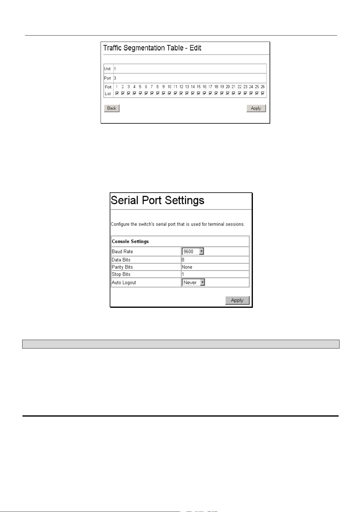
DES-3226S Layer 2 Fast Ethernet Switch User’s Guide
Figure 6 - 20. Traffic Segmentation – Edit
To configure Traffic Segmentation for a port, select the ports from the Port List that are allowed to receive forwarded frames
from the port that is being configured. Click the Apply button to add the ports to the forward list.
Serial Port Settings
The Serial Port Settings window allows the configuration of the Switch’s serial port.
Click on the Serial Port Settings link from the Basic Setup folder.
Figure 6 - 21. Serial Port Settings
The following fields can then be set for the serial port:
Parameter Description
Baud Rate
Data Bits
Stop Bits
Auto-Logout
Set the serial bit rate used to communicate with a management station. The console baud
rate is 9600 bits per second.
Displays the number of bits that make up a word when communicating with the
management station. The console interface uses 8 data bits.
Displays the number of bits used to indicate that a word has been completely transmitted.
The console interface uses 1 stop bit.
This sets the time the interface can be idle before the Switch automatically logs-out the
user. The options are 2 mins, 5 mins, 10 mins, 15 mins, or Never.
56
Page 64

DES-3226S Layer 2 Fast Ethernet Switch User’s Guide
SNTP and Time Settings
Use the Current Time Settings and Time Zone/DST Settings menus to configure the system time settings manual or use SNTP
service.
Current Time
The Current Time Settings menu is used to set system time. SNTP service can be enabled and configured here or use manual
settings. The read-only information here includes:
• System Boot Time – Time elapsed since last boot up sequence.
• Current Time – Current System Time expressed HH:MM:SS
• Time Source – Source of time settings, SNTP or interneal system clock.
Figure 6 - 22. Time Settings
57
Page 65

DES-3226S Layer 2 Fast Ethernet Switch User’s Guide
Configure the following settings in the Current Time Settings menu:
Parameter Description
SNTP State
SNTP Primary Server
Enable or Disable SNTP service
Enter the IP address of the primary server the SNTP information will be taken
from.
SNTP Secondary Server
Enter the IP address of the secondary server the SNTP information will be taken
from in the event the primary server is unavailable.
SNTP Polling Interval
This is the interval between requests for updated SNTP information. The polling
interval ranges from 30 to 99,999 seconds.
Set Current Time
Year
Month
Day
Time in HH MM SS
Select the year for manual date setting.
Select the month for manual date setting.
Select the day of the month for manual date setting.
Set time for system clock using 24-hour time clock (military time) notation.
Figure 6 - 23. Time Zone/DST Settings
58
Page 66

DES-3226S Layer 2 Fast Ethernet Switch User’s Guide
Daylight Savings Time settings can be enabled and set using either a formula for Repeating DST settings or using a definitive
date, Annual DST settings.
Parameter Description
DST State
DST Offset (in minutes)
Time Zone Offset (+/- GMT)
Enable or Disable the DST seasonal time adjustment for the Switch.
Choose to add (+) or subtract (-) time to adjust for time zone relative to GMT.
DST Repeating Settings
From Which Week (of the
month)?
From Which Day (of the
week)?
From Which Month?
From What Time HH:MM?
To Which Week?
To Which Day?
To Which Month?
To What Time HH:MM?
DST Annual Settings
From What Month?
From What Date?
From What Time?
To What Month?
To What Date?
To What Time?
Select the week of the month in which DST begins.
Select the day of the week in which DST begins.
Select the month in which DST begins.
Select the time of day to begin DST. Time is expressed using a 24-hour clock
using the hour and minute only.
Select the week of the month in which DST ends.
Select the day of the week in which DST ends.
Select the month in which DST ends.
Select the time of day to end DST. Time is expressed using a 24-hour clock.
Select the month in which DST begins.
Choose the specific date (day of the month) to begin DST.
Select the time of day to begin DST. Time is expressed using a 24-hour clock using
the hour and minute only.
Select the month in which DST ends.
Choose the specific date (day of the month) to begin DST.
Select the time of day to end DST. Time is expressed using a 24-hour clock.
59
Page 67

DES-3226S Layer 2 Fast Ethernet Switch User’s Guide
n
p
d
Network Management
The DES-3226S incorporates a flexible SNMP management for the Switching environment. SNMP management can be
customized o suit the needs of the networks and the preferences of the network administrator. Use the SNMP V3 menus to
select the SNMP version used for specific tasks.
SNMP Settings
The DES-3226S supports the Simple Network Management Protocol (SNMP) versions 1, 2c, and 3. The SNMP version used
to monitor and control the Switch can be specified by the administrator. The three versions of SNMP vary in the level of
security provided between the management station and the network device.
SNMP settings are configured using the menus located on the SNMP V3 folder of the web manager. Workstations on the
network that are allowed SNMP privileged access to the Switch can be restricted with the Management Station IP Address
menu.
SNMP View Table
The SNMP View Table is used to assign views to community strings that define which MIB objects can be accessed by an
SNMP manager.
To delete an existing View Table
entry, click the selection button o
the far left that corresponds to the
ort you want to configure an
click the Delete button. To create
a new entry, click the New button,
a separate menu will appear.
Figure 6 - 24. SNMP View Table
Figure 6 - 25. SNMP View Table – Add New
60
Page 68

DES-3226S Layer 2 Fast Ethernet Switch User’s Guide
Parameter Description
View Name
Subtree
View Type
Type an alphanumeric string of up to 32 characters. This is used to identify the new
SNMP view being created.
Type the Object Identifier (OID) Subtree for the view. The OID identifies an object tree
(MIB tree) that will be included or excluded from access by an SNMP manager.
Select Included to include this object in the list of objects that an SNMP manager can
access. Select Excluded to exclude this object from the list of objects that an SNMP
manager can access.
SNMP Group Table
The SNMP Group created with this table maps SNMP users (identified in the SNMP User Table) to the views created in the
previous menu.
Figure 6 - 26. SNMP Group Table
To delete an existing entry, click the selection button on the far left that corresponds to the port you want to configure and click
the Delete button. To create a new entry, click the New button, a separate menu will appear.
Figure 6 - 27. SNMP Group – Add New
61
Page 69

DES-3226S Layer 2 Fast Ethernet Switch User’s Guide
Parameter Description
Group Name
Read View Name
Write View Name
Notify View Name
Security Model
Security Level
Type an alphanumeric string of up to 32 characters. This is used to identify the new
SNMP group of SNMP users.
This name is used to specify the SNMP group created can request SNMP messages.
Specify a SNMP group name for users that are allowed SNMP write privileges to the
Switch’s SNMP agent.
Specify a SNMP group name for users that can receive SNMP trap messages generated
by the Switch’s SNMP agent.
Use the pull-down menu to select the SNMP version. Select one of the following:
SNMPv1 – Specifies that SNMP version 1 will be used.
SNMPv2 – Specifies that SNMP version 2c will be used. The SNMP v2c supports both
centralized and distributed network management strategies. It includes improvements in
the Structure of Management Information (SMI) and adds some security features.
USM – (User-based Security Module) Specifies that the SNMP version 3 will be used.
SNMP v3 provides secure access to devices through a combination of authentication and
encrypting packets over the network.
Use the pull-down menu to select the SNMP version:
NoAuthNoPriv − Specifies that there will be no authorization and no encryption of packets
sent between the Switch and a remote SNMP manager.
AuthNoPriv − Specifies that authorization will be required, but there will be no encryption
of packets sent between the Switch and a remote SNMP manager.
AuthPriv − Specifies that authorization will be required, and that packets sent between the
Switch and a remote SNMP manger will be encrypted.
SNMP Community Table
Use this table to create an SNMP community string to define the relationship between the SNMP manager and an agent. The
community string acts like a password to permit access to the agent on the Switch. One or more of the following
characteristics can be associated with the community string:
An Access List of IP addresses of SNMP managers that are permitted to use the community string to gain access to the
Switch’s SNMP agent.
An MIB view that defines the subset of all MIB objects that will be accessible to the SNMP community.
Read/write or read-only level permission for the MIB objects accessible to the SNMP community
Figure 6 - 28. SNMP Community Table
To delete an existing entry, click the selection button on the far left that corresponds to the port you want to configure and click
the Delete button. To create a new entry, click the New button, a separate menu will appear. Configure the parameters as
desired and click the Apply button to add the new string to the SNMP Community Table.
62
Page 70

DES-3226S Layer 2 Fast Ethernet Switch User’s Guide
Figure 6 - 29. SNMP Community Table – Add New
Configure the following for the new SNMP Community entry:
Parameter Description
Community Name
View Name
Access Right
Type an alphanumeric string of up to 33 characters that is used to identify members of an
SNMP community. This string is used like a password to give remote SNMP managers
access to MIB objects in the Switch’s SNMP agent.
Type an alphanumeric string of up to 32 characters that is used to identify the group of
MIB objects that a remote SNMP manager is allowed to access on the Switch. The view
name must exist in the SNMP View Table.
Use the pull-down menu to select the access right:
read_only − Specifies that SNMP community members using the community string
created with this command can only read the contents of the MIBs on the Switch.
read_write − Specifies that SNMP community members using the community string
created with this command can read from and write to the contents of the MIBs on the
Switch.
SNMP Engine ID
The Engine ID is a unique identifier used for SNMP V3 implementations. This is an alphanumeric string used to identify the
SNMP engine on the Switch.
Figure 6 - 30. Engine ID
To change the Engine ID, type the new Engine ID in the space provided and click the Apply button.
63
Page 71

DES-3226S Layer 2 Fast Ethernet Switch User’s Guide
SNMP Host Table
Use the SNMP Host Table to set up trap recipients.
Figure 6 - 31. SNMP Host Table
To delete an existing entry, click the selection button on the far left that corresponds to the port you want to configure and click
the Delete button. To create a new entry, click the New button, a separate menu will appear.
Figure 6 - 32. SNMP Host Table – Add New
Parameter Description
IP Address
SNMP Version
Community String or
SNMP V3 User Name
Type the IP address of the remote management station that will serve as the SNMP host
for the Switch.
From the pull-down menu select:
V1 – To specifies that SNMP version 1 will be used.
V2 – To specify that SNMP version 2 will be used.
V3 – To specify that the SNMP version 3 will be used.
Type in the community string or SNMP V3 user name as appropriate.
64
Page 72

DES-3226S Layer 2 Fast Ethernet Switch User’s Guide
SNMP User Table
Use the SNMP User Table to create a new SNMP user and add the user to an existing SNMP group or to a newly created
group.
Figure 6 - 33. SNMP User Table
To delete an existing entry, click the selection button on the far left that corresponds to the port you want to configure and click
the Delete button. To create a new entry, click the New button, a separate menu will appear.
Figure 6 - 34. SNMP User Table – Add New
Parameter Description
User Name
Type in the new SNMP V3 user name or community string for V1 or V2. This can be any
alphanumeric name of up to 32 characters that will identify the new SNMP user.
Group Name
Type in the new SNMP V3 group name. Again, this can be any alphanumeric name of up
to 32 characters that will identify the SNMP group the new SNMP user will be associated
with.
SNMP Version
From the pull-down menu select:
V1 – To specifies that SNMP version 1 will be used.
V2 – To specify that SNMP version 2 will be used.
V3 – To specify that the SNMP version 3 will be used.
If Encryption (V3 only) is
checked configure also:
Auth-Protocol
In the Space provided, type an alphanumeric sting of between 8 and 20 characters that
will be used to authorize the agent to receive packets for the host.
From the pull-down menu select:
MD5 − To specify that the HMAC-MD5-96 authentication level will be used.
SHA − To specify that the HMAC-SHA-96 authentication level will be used.
If Encryption (V3 only) is
checked configure also:
In the Space provided, type an alphanumeric string of between 8 and 16 characters that
will be used to encrypt the contents of messages the host sends to the agent.
Priv-Protocol
65
Page 73

DES-3226S Layer 2 Fast Ethernet Switch User’s Guide
Switch Utilities
TFTP Utilities
Trivial File Transfer Protocol (TFTP) services allow the Switch firmware to be upgraded by transferring a new firmware file
from a TFTP server to the Switch. A configuration file can also be loaded into the Switch from a TFTP server, Switch settings
can be saved to the TFTP server, and a history log can be uploaded from the Switch to the TFTP server.
NOTE: To get the latest firmware for the Switch go to the D-Link website:
www.dlink.com.
Update Firmware from Server
To update the Switch’s firmware, click on the Basic Setup folder and then the Switch Utilities folder and then the TFTP
Services folder and finally click on the Download Firmware from TFTP Server link:
Figure 6 - 35. Download Firmware from Server
Select which Switch of a Switch stack you want to update the firmware on. This allows the selection of a particular Switch
from a Switch stack if you have installed the optional stacking module and have properly interconnected the Switches.
1. Enter the IP address of the TFTP server in the Server IP Address field.
2. The TFTP server must be on the same IP subnet as the Switch.
3. Enter the path and the filename to the firmware file on the TFTP server. Note that in the above example, the firmware
file is in the root directory of the D drive of the TFTP server.
4. The TFTP server must be running TFTP server software to perform the file transfer. TFTP server software is a part of
many network management software packages – such as NetSight, or can be obtained as a separate program.
5. Click Download to record the IP address of the TFTP server. Use the Save Settings to enter the address into NV-
RAM.
6. Click Start to initiate the file transfer.
66
Page 74

DES-3226S Layer 2 Fast Ethernet Switch User’s Guide
Use Configuration File on Server
To download a configuration file for the Switch’s, click on the Basic Setup folder and then the Switch Utilities folder and
then the TFTP Services folder and finally click on the Download Configuration from TFTP Server link:
Figure 6 - 36. Use Configuration File on Server
1. Enter the IP address of the TFTP server and specify the location of the Switch configuration file on the TFTP server.
2. Click Save Settings to record the IP address of the TFTP server.
3. Use Save Changes from the Maintenance menu to enter the address into NV-RAM.
4. Click Start to initiate the file transfer.
Save Settings To Server
To download a configuration file for the Switch’s, click on the Basic Setup folder and then the Switch Utilities folder and
then the TFTP Services folder and finally click on the Upload Settings to TFTP Server link:
Figure 6 - 37. Save Settings To TFTP Server
Enter the IP address of the TFTP server and the path and filename of the settings file on the TFTP server and click Save
Settings. Click Upload to initiate the file transfer.
67
Page 75

DES-3226S Layer 2 Fast Ethernet Switch User’s Guide
Save History Log to Server
To download a configuration file for the Switch’s, click on the Basic Setup folder and then the Switch Utilities folder and
then the TFTP Services folder and finally click on the Upload history Log to TFTP Server link:
Figure 6 - 38. Save Switch History to TFTP Server
Enter the IP address of the TFTP server and the path and filename for the history log on the TFTP server. Click Save Settings
to make the changes current. Click Upload to initiate the file transfer.
Ping Test
Ping is a small program that sends data packets to the IP address you specify. The destination node then returns the packets to
the Switch. This is very useful to verify connectivity between the Switch and other nodes on the network.
Figure 6 - 39. Ping Test Screen
The Infinite times checkbox, in the Number of Repetitions field, tells ping to keep sending data packets to the specified IP
address until the program is stopped.
68
Page 76

DES-3226S Layer 2 Fast Ethernet Switch User’s Guide
Advanced Setup
Advanced setup menus include menus used to setup VLANs, change QoS scheduling, configure link aggregation, adjust
Spanning Tree and Rapid Spanning Tree configuration, setup 802.1x parameters, assign unicast and multicast forwarding and
configure port mirroring.
Configuring VLANs
To create a new 802.1Q VLAN:
The VLAN menu adds an entry to edit the VLAN definitions and to configure the port settings for IEEE 802.1Q VLAN
support. Go to the Advanced Setup folder, select VLAN Configurations, and click the 802.1Q VLANs link to open the
following dialog box:
Figure 6 - 40. 802.1Q VLANs
To delete an existing 802.1Q VLAN, click the corresponding click-box to the left of the VLAN you want to delete from the
Switch and then click the Delete button.
To create a new 802.1Q VLAN, click the New button:
Figure 6 - 41. 802.1Q Static VLANs Entry Settings – Add
69
Page 77

DES-3226S Layer 2 Fast Ethernet Switch User’s Guide
To edit an existing 802.1Q VLAN, click the corresponding click-box and then click the Edit icon to open the following
dialog box:
Figure 6 - 42. 802.1Q Static VLANs Entry Settings – Edit
The following fields can then be set in either the Add or Edit dialog boxes:
Parameter Description
VLAN ID (VID)
Allows the entry of a VLAN ID in the Add dialog box, or displays the VLAN ID of an
existing VLAN in the Edit dialog box. VLANs can be identified by either the VID or the
VLAN name. The Auto Assign click box will instruct the Switch to assign VLAN IDs − in
ascending numerical order starting with 1 − to each VLAN as it is created.
VLAN Name
Allows the entry of a name for the new VLAN in the Add dialog box, or for editing the
VLAN name in the Edit dialog box.
Advertisement
Advertising can be enabled or disabled using this pull-down menu. Advertising allows
members to join this VLAN through GVRP.
Port
Tagged/Untagged
Allows an individual port to be specified as member of a VLAN.
Allows an individual port to be specified as Tagging. A Check in the Tagged field
specifies the port as a Tagging member of the VLAN. When an untagged packet is
transmitted by the port, the packet header is changed to include the 32-bit tag associated
with the VID (VLAN Identifier – see below). When a tagged packet exits the port, the
packet header is unchanged.
Untagged
Allows an individual port to be specified as Untagged. When an untagged packet is
transmitted by the port, the packet header remains unchanged. When a tagged packet
exits the port, the tag is stripped and the packet is changed to an untagged packet.
Egress
Egress Member - specifies the port as being a static member of the VLAN. Egress
Member Ports are ports that will be transmitting traffic for the VLAN. These ports can be
either tagged or untagged.
Forbidden
Forbidden Non-Member - specifies the port as not being a member of the VLAN and that
the port is forbidden from becoming a member of the VLAN dynamically.
The Port VLAN ID (PVID) dialog box, shown below, allows you to determine whether the Switch will share its VLAN
configuration information with other GARP VLAN Registration Protocol (GVRP) enabled Switches. In addition, Ingress
Checking can be used to limit traffic by filtering incoming packets whose PVID does not match the PVID of the port.
70
Page 78

DES-3226S Layer 2 Fast Ethernet Switch User’s Guide
Figure 6 - 43. Port VLAN ID (PVID)
The following fields can be set:
Parameter Description
PVID
A Port VLAN Identifier is a classification mechanism that associates a port with a specific
VLAN and is used to make forwarding decisions for untagged packets received by the
port. For example, if port #2 is assigned a PVID of 3, then all untagged packets received
on port #2 will be assigned to VLAN 3. This number is generally the same as the VID#
number assigned to the port in the Edit 802.1Q VLANs menu above.
GVRP <Disabled>
The Group VLAN Registration Protocol (GVRP) enables the port to dynamically become a
member of a VLAN.
Ingress Checking
<Disabled>
This field can be toggled using the space bar between Enabled and Disabled. Enabled
enables the port to compare the VID tag of an incoming packet with the PVID number
assigned to the port. If the two are different, the port filters (drops) the packet. Disabled
disables Ingress filtering.
71
Page 79

DES-3226S Layer 2 Fast Ethernet Switch User’s Guide
To enable or disable GVRP, globally, on the Switch:
Go to the VLAN Configurations link and click on the Switch GVRP link:
Figure 6 - 44. – Switch GVRP
Parameter Description
GVRP <Disabled>
Group VLAN Registration Protocol (GVRP) – this enables and disables GVRP on the
Switch without changing the port GVRP settings.
Asymmetric VLANs
The DES-3226S supports Asymmetric VLANs implementation for more efficient use of shared resources such as server or
gateway devices. An asymmetric VLAN can be set up to allow a server (or several servers) to communicate with several
clients through a single physical link on the Switch. At the same time however, the clients are not allowed to link to each other
directly. For example, asymmetric VLANs can be set up so that the network email server can be accessed by all email clients.
All email clients can send and receive data packets through the port connected to the email server, but they are not allowed to
send and receive data to the remaining ports. The email server can freely associate with all ports, that is, all clients connected
to the Switch.
The key difference between conventional 802.1q VLAN implementation or symmetric VLANs, and asymmetric VLANs is in
how address mapping is handled. Symmetric VLANs use separate address tables so there is no address sharing between
VLANs. Asymmetric VLANs can use a single, shared address table. Address sharing however takes place in only one
direction. In the example above, the VLAN created for the port connected to the email server has the entire address table at its
disposal so that any address can be mapped to its port (PVID).
This feature can be enabled with the following important restrictions:
• Asymmetric VLAN support is limited to standalone Switches.
• Each participating port must be untagged.
• GVRP and IGMP Snooping is not supported.
When Asymmetric VLANs have been enabled, a unique PVID is assigned to all ports creating a separate VLAN for each port.
Each port is still able to receive frames from the defult VLAN. Asymmetric VLANs are disabled by default.
Figure 6 - 45. Asymmetric VLANs (enable or disable)
To enable Asymmetric VLANs for a standalone Switch, select Enabled and click the Apply button.
72
Page 80

DES-3226S Layer 2 Fast Ethernet Switch User’s Guide
Configure QoS (Quality of Service)
The DES-3226S Switch supports 802.1p priority queuing. The Switch has 4 priority queues. These priority queues are
numbered from 0 (Class 0) — the lowest priority queue — to 3 (Class 3) — the highest priority queue. The eight priority
queues specified in IEEE 802.1p (p0 to p7) are mapped to the Switch’s priority queues as follows:
• p1 and p2 are assigned to the Switch’s Class 0 queue.
• p0 and p3 are assigned to the Switch’s Class 1 queue.
• p4 and p5 are assigned to the Switch’s Class 2 queue.
• p6 and p7 are assigned to the Switch’s Class 3 queue.
Priority scheduling is implemented using two types of methods, strict priority and round-robin priority. If no changes are made
to the QoS priority scheduling settings the method used is strict priority.
For strict priority-based scheduling, packets residing in the higher priority queues are transmitted first. Only when these
queues are empty, are packets of lower priority allowed to be transmitted. Higher priority packets always receive preference
regardless of the amount of lower priority packets in the buffer and regardless of the time elapsed since any lower priority
packets have been transmitted. By default the Switch is configured to empty the buffer using strict priority.
NOTICE: The default QoS scheduling arrangement is a strict priority schedule. To customize
scheduling to set up round-robin queue clearing, the MAX. Latency and MAX. Packets values need
to be changed using the config scheduling command. See config scheduling below.
To use implement round-robin (weighted) priority, the Switch’s four priority queues can be configured to reduce the buffer in a
round-robin fashion - beginning with the highest priority queue, and proceeding to the lowest priority queue before returning to
the highest priority queue.
The weighted-priority based scheduling alleviates the main disadvantage of strict priority-based scheduling − in that lower
priority queues get starved of bandwidth − by providing a minimum bandwidth to all queues for transmission. This is
accomplished by configuring the maximum number of packets allowed to be transmitted from a given priority queue and the
maximum amount of time a given priority queue will have to wait before being allowed to transmit its accumulated packets.
This establishes a Class of Service (CoS) for each of the Switch’s four hardware priority queues.
The possible range for maximum packets is: 0 to 255 packets.
The possible range for maximum latency is: 0 to 255 (in increments of 16 microseconds each).
Remember that the DES-3226S has four priority queues (and thus four Classes of Service) for each port on the Switch.
Configuring QoS Output Scheduling
Click the Configure QoS link on the Advanced Setup menu, and the click on the QoS Output Scheduling link:
Figure 6 - 46. QoS Output Scheduling
The MAX. Packets field specifies the number of packets that a queue will transmit before surrendering the transmit buffer to
the next lower priority queue in a round-robin fashion. The default value of 0 combined with the default MAX. Latency value
of 0 will enforce a strict scheduling for output queues. The maximum value for MAX. Packets is 255.
The MAX. Latency field specifies the maximum amount of time—in multiples of 16 microseconds—that a queue will have to
wait before being given access to the transmit buffer. The MAX. Latency is a priority queue timer. When it expires, it
73
Page 81

DES-3226S Layer 2 Fast Ethernet Switch User’s Guide
overrides the round-robin queuing and gives the priority queue that it was set for access to the transmit buffer. The default
value of 0 combined with the default MAX. Packets value of 0 will enforce a strict scheduling for output queues. The
maximum value for MAX. Latency is 255.
NOTE: There is a small amount of additional latency introduced because the priority queue that is
transmitting at the time the MAX. Latency time expires will finish transmitting its current packet before
giving up the transmit buffer.
Configuring 802.1p User Priority
The DES-3226S allows the assignment of a User Priority to each of the 802.1p priorities.
Figure 6 - 47. QoS Class of Traffic
Once you have assigned a maximum number of packets and a maximum latency to a given Class of Service on the Switch, you
can then assign this Class to each of the 8 levels of 802.1p priorities.
74
Page 82

DES-3226S Layer 2 Fast Ethernet Switch User’s Guide
Configuring Default Priority
The Switch allows the assignment of a default 802.1p priority to each port on the Switch.
Click on the Default Priority link:
Figure 6 - 48. Priority Based on Port
This window allows you to assign a default 802.1p priority to any given port on the Switch. The priority queues are numbered
from 0 − the lowest priority − to 7 − the highest priority.
75
Page 83

DES-3226S Layer 2 Fast Ethernet Switch User’s Guide
t
t
d
Bandwidth Control
The bandwidth control settings are used to place a ceiling on the transmitting and receiving data bit rates for any port.
To change the maximum allowed bandwidth
for a given port:
In the Bandwidth Control Table, click the
selection button in the far left column tha
corresponds to the port you want to configure
and click the Edit button. A new dialog box
used to edit bandwidth settings opens.
Figure 6 - 49. Edit Port Bandwidth
To limit either the Rx or Tx rates, deselec
the No Limit check box and type the desire
rate. Rates can be expressed using whole
numbers up to the maximum available rate
for the port.
Figure 6 - 50. Bandwidth Control Table
76
Page 84

DES-3226S Layer 2 Fast Ethernet Switch User’s Guide
Port Mirroring
To configure a port for port mirroring:
Click the Mirroring link and then the Target Port Selection link:
Figure 6 - 51. Target Port Selection
The target port is the port where information will be duplicated and sent for capture and network analysis. This is the port
where a network analyzer would be attached to capture packets duplicated from the source port.
Up to 25 entries can be made to the port mirroring table, but it should be noted that a faster port (a 1000 Mbps Gigabit Ethernet
port, for example) should not be mirrored to a slower port (one of the 24 100 Mbps Fast Ethernet port), because many packets
will be dropped.
The following fields can be set:
Parameter Description
Source Port
Direction <Ingress>
Allows the entry of the port number of the port to be mirrored. This port is the source of the
packets to be duplicated and forwarded to the Target port.
This field can be toggled between Either, Ingress and Egress. Ingress mirrors only
received packets, while Egress mirrors only transmitted packets.
77
Page 85

DES-3226S Layer 2 Fast Ethernet Switch User’s Guide
Forwarding and Filtering
MAC Address Aging Time
The MAC Address Aging Time specifies the length of time a learned MAC Address will remain in the forwarding table
without being accessed (that is, how long a learned MAC Address is allowed to remain idle). The Aging Time can be set to
any value between 300 and 1,000,000 seconds.
To configure the MAC Address Aging Time, click on the Forwarding folder and then the MAC Forwarding folder, then
click on the MAC Address Aging Time link:
Figure 6 - 52. MAC Address Aging Time
Unicast MAC Address Forwarding
MAC addresses can be statically entered into the Switch’s MAC Address Forwarding Table. These addresses will never age
out.
To enter a MAC address into the Switch’s forwarding table, click on the Forwarding folder and then the MAC Forwarding
folder and then click the Unicast MAC Address Setting:
Figure 6 - 53. Unicast MAC Address Settings
78
Page 86

DES-3226S Layer 2 Fast Ethernet Switch User’s Guide
To add a new MAC address to the MAC Address Forwarding Table, click the New button:
Figure 6 - 54. Unicast MAC Address Settings − Add
To edit an existing entry in the MAC address in the MAC Address Forwarding Table, click the Edit button:
Figure 6 - 55. Unicast MAC Address Settings − Edit
The following fields can be set:
Parameter Description
MAC Address
VLAN Name
Unit
Port
Allows the entry of the MAC address of an end station that will be entered into the
Switch’s static forwarding table when adding a new entry. Displays the currently selected
MAC address when editing.
Allows the entry of the VLAN Name of the VLAN the MAC address below is a member of
− when editing. Displays the VLAN the currently selected MAC address is a member of −
when editing an existing entry.
Allows the selection of a given Switch from a Switch stack − if you have the optional
stacking module installed and have properly interconnected the Switches in a Switch
stack.
Allows the entry of the port number on which the MAC address entered above resides.
79
Page 87

DES-3226S Layer 2 Fast Ethernet Switch User’s Guide
Multicast MAC Address Forwarding
Multicast MAC addresses can be statically entered into the Switch’s MAC Address Forwarding Table. These addresses will
never age out.
To enter a Multicast MAC address into the Switch’s forwarding table, click on the Forwarding folder and then the MAC
Forwarding folder and then click on the Multicast MAC Address Settings link:
Figure 6 - 56. Multicast MAC Address Settings
To add a new multicast MAC address to the Switch’s forwarding table, click the New button:
Figure 6 - 57. Multicast MAC Address Settings − Add
To edit an existing entry to the Switch’s forwarding table, click the entry’s corresponding click-box and then click the edit
button:
Figure 6 - 58. Multicast MAC Address Settings − Edit
80
Page 88

DES-3226S Layer 2 Fast Ethernet Switch User’s Guide
The following fields can be set:
Parameter Description
MAC Address:[ ]
Allows the entry of the MAC address of an end station that will be entered into the
Switch’s static forwarding table.
VLAN Name
Allows the entry of the VLAN name of the VLAN the MAC address below is a member of −
when adding a new entry to the table. Displays the VLAN name of the VLAN the MAC
address is a member of − when editing an existing entry.
Port: [ ]
None
Egress
Allows the entry of the port number on which the MAC address entered above resides.
Specifies the port as being none.
Specifies the port as being a source of multicast packets originating from the MAC
address specified above.
Forbidden
Forbidden Non-Member - specifies the port as not being a member of the VLAN and that
the port is forbidden from becoming a member of the VLAN dynamically.
81
Page 89

DES-3226S Layer 2 Fast Ethernet Switch User’s Guide
r
u
t
Multicast Port Filtering
This command configures the multicast filtering and forwarding for specified ports.
Click the selection button on the fa
left that corresponds to the port yo
want to configure and click the Edi
button. This will open the following
dialog box:
Figure 6 - 59. Multicast Port Filtering
82
Page 90

DES-3226S Layer 2 Fast Ethernet Switch User’s Guide
Figure 6 - 60. Edit Multicast Port Filtering
To configure Multicast Port Filtering, select the ports from the Port List. Click the Apply button to add the ports to the forward
list.
Parameter Description
Port
forward_all_groups
forward_unregistered_groups
filter_unregistered_groups
Configure Ports from __ to __
Select the port number to configure.
Forward all multicast packets, i.e. no filtering takes places since multicast
packets from unregistered and registered multicast groups are forwarded in the
specified port group.
Forward only multicast packets from unregistered multicast groups. Multicast
packets from registered groups are dropped.
Filter all multicast packets from unregistered multicast groups. Multicast packets
from registered groups are forwarded.
Use this to specify a consecutively numbered group of ports on the Switch for
configuration.
83
Page 91

DES-3226S Layer 2 Fast Ethernet Switch User’s Guide
Broadcast/Multicast Storm Control
Broadcast and Multicast storms consist of broadcast or multicast packets that flood and/or are looped on a network causing
noticeable performance degradation and, in extreme cases, network failure.
The DES-3226S allows some control over broadcast/multicast storms by setting thresholds on the number of
broadcast/multicast packets received (in thousands of packets per second or Kpps), and then following a user-specified course
of action when this threshold is exceeded.
To configure Broadcast/Multicast storm control:
Click on the Forwarding folder, and then on the MAC Forwarding folder, and finally on the Broadcast/Multicast Storm
Control link:
Figure 6 - 61. Broadcast/Multicast Storm Control
Broadcast/Multicast storm control is applied to groups of ports on the DES-3226S. Group 1 contains ports 1 through 8.
Group 2 contains ports 9 through 16. Group 3 contains ports 17 through 24. Group 4 and Group 5 contain the ports on the
optional plug-in module.
The Upper Threshold (Kpps) sets the rate of broadcast or multicast packets received on any of the ports in the corresponding
port group that will trigger the action to be taken by the Switch, as detailed below. A range of thousands of packets received
per second (Kpps) between 0 and 255 can be specified.
When any one of the ports contained within a given port group receives more broadcast or multicast packets per second than is
specified in the Upper Threshold (Kpps) field, the Switch will take the actions specified in the Broadcast Storm Mode,
Multicast Storm Mode, and the Destination Lookup Fail pull-down menus.
The Broadcast Storm Mode is Enabled or Disabled using the pull-down menu for the corresponding port group. When the
Broadcast Storm Mode is enabled, and a port contained within the corresponding port group receives more broadcast packets
than specified in the Upper Threshold (Kpps) field, the Switch will drop all broadcast packets received by any port in the port
group until the rate of broadcast packets received by the port group falls.
The Multicast Storm Mode is Enabled or Disabled using the pull-down menu for the corresponding port group. When the
Multicast Storm Mode is enabled, and a port contained within the corresponding port group receives more multicast packets
than specified in the Upper Threshold (Kpps) field, the Switch will drop all multicast packets received by any port in the port
group until the rate of multicast packets received by the port group falls.
The Destination Lookup Fail is Enabled or Disabled using the pull-down menu for the corresponding port group. When the
Destination Lookup Fail is enabled, and a port contained within the corresponding port group receives more destination
lookup failed packets than specified in the Upper Threshold (Kpps) field, the Switch will drop all destination lookup failed
packets received by any port in the port group until the rate of destination lookup failed packets received by the port group
falls.
84
Page 92

DES-3226S Layer 2 Fast Ethernet Switch User’s Guide
Spanning Tree
The Switch supports 802.1d Spanning Tree Protocol (STP) and 802.1w Rapid Spanning Tree Protocol (RSTP). RSTP is
compatible with 802.1d STP however the advantages of rapid network convergence is lost if the Switch is connect to a
segment that cannot support RSTP.
STP Switch Settings
Spanning Tree Protocol operates on two levels: on the Switch level, the settings are globally implemented. On the port level,
the settings are implemented on a per user-defined Group of ports basis.
Figure 6 - 62. STP Switch Settings
Configure the following parameters and click the Apply button to implement them:
Parameter Description
Status <Disabled>
Max Age: (6 - 40 sec)
<20 >
Hello Time: (1 - 10
sec) < 2 >
Forward Delay: (4 - 30
sec) <15 >
Priority: (0 - 61440)
<32768>
STP Version <RSTP > Choose RSTP (default) or STP Compatibility. Both versions use STP parameters in the
Tx Hold Count <3 >
Forwarding BPDU
<Enabled >
This field can be toggled between Enabled and Disabled using the pull-down menu. This
will enable or disable the Spanning Tree Protocol (STP), globally, for the Switch.
The Max. Age can be set from 6 to 40 seconds. At the end of the Max. Age, if a BPDU has
still not been received from the Root Bridge, your Switch will start sending its own BPDU to
all other Switches for permission to become the Root Bridge. If it turns out that your Switch
has the lowest Bridge Identifier, it will become the Root Bridge.
The Hello Time can be set from 1 to 10 seconds. This is the interval between two
transmissions of BPDU packets sent by the Root Bridge to tell all other Switches that it is
indeed the Root Bridge.
The Forward Delay can be from 4 to 30 seconds. This is the time any port on the Switch
spends in the listening state while moving from the blocking state to the forwarding state.
A Priority for the Switch can be set from 0 to 61440. This number is used in the voting
process between Switches on the network to determine which Switch will be the root
Switch. A low number indicates a high priority, and a high probability that this Switch will be
elected as the root Switch.
same way. RSTP is fully compatible with IEEE 802.1d STP and will function with legacy
equipment.
This is the maximum number of Hello packets transmitted per interval. The count can be
specified from 1 to 10. Default value = 3.
This can enabled or disabled. When it is enabled it allows the forwarding of STP BPDU
packets from other network devices when STP is disabled on the Switch. The default is
enabled.
85
Page 93

DES-3226S Layer 2 Fast Ethernet Switch User’s Guide
NOTE: The Hello Time cannot be longer than the Max. Age. Otherwise, a configuration error will
occur.
Observe the following formulas when setting the above parameters:
Max. Age ≤ 2 x (Forward Delay - 1 second)
Max. Age ≥ 2 x (Hello Time + 1 second)
STP Port Settings
For stacked Switch installations, first select the Unit to be configured.
To change STP settings for a port or a group of ports on the same Switch,
select the first (lowest numbered) port from the list and click the Edit
button, a separate menu will appear.
Figure 6 - 63. Edit STP Port Settings
Figure 6 - 64. STP Port Settings
In addition to setting Spanning Tree parameters for use on the Switch level, the Switch allows for the configuration of groups
of ports, each port-group of which will have its own spanning tree, and will require some of its own configuration settings. An
STP Group will use the Switch-level parameters entered above, with the addition of Port Priority and Port Cost.
An STP Group spanning tree works in the same way as the Switch-level spanning tree, but the root bridge concept is replaced
with a root port concept. A root port is a port of the group that is elected on the basis of port priority and port cost, to be the
connection to the network for the group. Redundant links will be blocked, just as redundant links are blocked on the Switch
level.
86
Page 94

DES-3226S Layer 2 Fast Ethernet Switch User’s Guide
The STP on the Switch level blocks redundant links between Switches (and similar network devices). The port level STP will
block redundant links within an STP Group.
It is advisable to define an STP Group to correspond to a VLAN group of ports.
The following fields can be set:
Parameter Description
Cost
A Port Cost can be set from 1 to 200000000. The lower the number, the greater
the probability the port will be chosen to forward packets.
Default port cost:
100Mbps port = 200000
Gigabit ports = 20000
Priority <128>
A Port Priority can be from 0 to 240. The lower the number, the greater the
probability the port will be chosen as the Root Port.
Migration <No>
Select Yes or No. Choosing Yes will enable the port to migrate from 802.1d STP
status to 802.1w RSTP status. RSTP can coexist with standard STP, however the
benefits of RSTP are not realized on a port where an 802.1d network connects to
an 802.1w enabled network. Migration should be enabled (yes) on ports
connected to network stations or segments that will be upgraded to 802.1w RSTP
on all or some portion of the segment.
Edge <No>
Select True or False. Choosing true designates the port as an edge port. Edge
ports cannot create loops, however an edge port can lose edge port status if a
topology change creates a potential for a loop. An edge port normally should not
receive BPDU packets. If a BPDU packet is received it automatically loses edge
port status. False indicates the port does not have edge port status.
P2P <Yes>
Select True or False. Choosing true indicates a point-to-point (p2p) shared link.
These are similar to edge ports however they are restricted in that a p2p port must
operate in full-duplex. Like edge ports, p2p ports transition to a forwarding state
rapidly thus benefiting from RSTP.
Configure Ports from __ to __
A consecutive group of ports may be configured starting with the selected port.
87
Page 95

DES-3226S Layer 2 Fast Ethernet Switch User’s Guide
MAC Notification
MAC address notification is used to monitor MAC addresses learned and entered into the forwarding database.
Global Settings
Figure 6 - 65. MAC Notification Global Settings
Configure the following MAC notification global settings:
Parameter Description
State
Interval
History Size
Enable or Disable MAC notification Switch-wide from the pull-down menu.
This is the time in seconds between notifications.
This is maximum number of entries listed in the history log used for notification. Up to 500
entries can be specified.
MAC Notification Port Settings
Enable or disable MAC notification for ports with the menu below.
Figure 6 - 66. MAC Notification Port Settings
88
Page 96

DES-3226S Layer 2 Fast Ethernet Switch User’s Guide
To change MAC Notification settings for a port or a group of ports on the same Switch, select the first (lowest numbered) port
from the list and click the Edit button, a separate menu will appear.
Figure 6 - 67. MAC Notification Port Settings - Edit
Configure the following MAC notification global settings:
Parameter Description
Port
State
Configure Ports from __ to __
Select the port or lowest number of the group of ports being configured.
Enable or Disable MAC notification for the port from the pull-down menu.
A consecutive group of ports may be configured starting with the selected port.
Link Aggregation
Link aggregation allows several ports to be grouped together and to act as a single link. This gives a bandwidth that is a
multiple of a single link’s bandwidth.
Link aggregation is most commonly used to link a bandwidth intensive network device or devices – such as a server – to the
backbone of a network.
The Switch allows the creation of up to 6 link aggregation groups, each group consisting of up of up to 8 links (ports). The
aggregated links must be contiguous (they must have sequential port numbers) except the two (optional) Gigabit ports – which
can only belong to a single link aggregation group. A link aggregation group may not cross an 8-port boundary, starting with
port 1 (a group may not contain ports 8 and 9, for example) and all of the ports in the group must be members of the same
VLAN. Further, the aggregated links must all be of the same speed and should be configured as full-duplex.
The configuration of the lowest numbered port in the group becomes the configuration for all of the ports in the aggregation
group. This port is called the Master Port of the group, and all configuration options – including the VLAN configuration – that
can be applied to the Master Port are applied to the entire link aggregation group.
Load balancing is automatically applied to the ports in the aggregated group, and a link failure within the group causes the
network traffic to be directed to the remaining links in the group.
The Spanning Tree Protocol will treat a link aggregation group as a single link, on the Switch level. On the port level, the STP
will use the port parameters of the Master Port in the calculation of port cost and in determining the state of the link
aggregation group. If two redundant link aggregation groups are configured on the Switch, STP will block one entire group –
in the same way STP will block a single port that has a redundant link.
89
Page 97

DES-3226S Layer 2 Fast Ethernet Switch User’s Guide
Figure 6 - 68. Link Aggregation Algorithm − Selection
Mac_source − Indicates that the Switch should examine the MAC source address.
Mac_destination − Indicates that the Switch should examine the MAC destination address.
Mac_source_dest − Indicates that the Switch should examine the MAC source and destination addresses.
IP_source − Indicates that the Switch should examine the IP source address.
IP_destination − Indicates that the Switch should examine the IP destination address.
IP_source_dest − Indicates that the Switch should examine the IP source and destination addresses.
To configure a link aggregation group, click on the Link Aggregation link from the Advanced Setup folder:
Figure 6 - 69. Link Aggregation
To add a new multicast MAC address to the Switch’s forwarding table, click the New button:
90
Page 98

DES-3226S Layer 2 Fast Ethernet Switch User’s Guide
Figure 6 - 70. Link Aggregation − New
To edit an existing entry to the Switch’s forwarding table, click the entry’s corresponding click-box and then click the edit
button:
Figure 6 - 71. Link Aggregation − Edit
The following fields can be set:
Parameter Description
Group ID
Allows the entry of a number used to identify the link aggregation group − when adding a
new group. Displays the Group ID of the currently selected link aggregation group −
when editing and existing entry.
Type
Select the type of link aggregation used for the group. If type is not specified the default
type is Static. Aggregated ports may be either LACP or Static. LACP indicates the port
group as LACP compliant so they can be connected to a n LACP compliant device.
Static trunk groups are not able to adjust dynamically and both devices connected to the
static trunk group must be manually configured if the composition of the group is
changed.
Master Port <1>
Unit
The Master port of link aggregation group.
Allows the selection of a particular Switch in a Switch stack, if you have the optional
stacking module installed and have properly interconnected the Switches in the Switch
stack.
Port Member
Status <Disabled>
Allows the specification of the ports that will make up the link aggregation group.
This field can be toggled between Enabled and Disabled. This is used to turn a link
aggregation group on or off. This is useful for diagnostics, to quickly isolate a bandwidth
intensive network device or to have an absolute backup link aggregation group that is not
under automatic control.
91
Page 99

DES-3226S Layer 2 Fast Ethernet Switch User’s Guide
802.1X Configuration
The DES-3226S implements the server-side of the IEEE 802.1x Port-based Network Access Control. This mechanism is
intended to allow only authorized users, or other network devices, access to network resources by establishing criteria for each
port on the Switch that a user or network device must meet before allowing that port to forward or receive frames.
IEEE 802.1X operation must be enabled on the Switch before it will function. It will necessary to determine the whether to
port-based or MAC-based 802.1x authorization (see below).
802.1X State
To use 802.1x on the Switch, choose the type of authorization to use and click the Apply button.
Figure 6 - 72. 802.1X State
Port-based Authorization means that ports configured for 802.1x function (see 802.1X Port Settings) are initialized based on
the port number only and subject to any authorization parameters as configured.
MAC-based Authorization means that ports configured for 802.1x function (see 802.1X Port Settings) are initialized based on
port number and MAC address, then subject to any authorization parameters configured. Additional configuration is required
to list the MAC address in the authorization list and to specify the port from which request is made (see Initialize Ports below).
802.1X Port Settings
Existing 802.1X port settings are displayed and can be con figured using the menu below.
Figure 6 - 73. 802.1X Port Settings
92
Page 100

DES-3226S Layer 2 Fast Ethernet Switch User’s Guide
Click the selection button on the far left that corresponds to the port you want to configure and click the Edit button, a separate
menu will appear.
Parameter Description
Port status
PAE State
Lists the current status of port, Authorized or Unauthorized.
Displays the administrative control over the port’s authorization status. Force Authorized
forces the Authenticator of the port to become Authorized. Force Unauthorized forces the
port to become Unauthorized.
Backend State
OperCtlState
Shows the current state of the Backend Authenticator.
This displays whether a controlled Port that is unauthorized will exert control over
communication in both receiving and transmitting directions, or just the receiving
direction.
Figure 6 - 74. 802.1X Port Settings – Edit
93
 Loading...