

Page 1

DES-3226L
Release 3
Layer 2 Switch
24 Port 10/100 Managed Switch
Plus 2 Combo Gigabit Copper/SFP Ports
Web User Guide
Business Class Networking
Page 2

Page 3

Table of Contents
Table of Contents . . . . . . . . . . . . . . . . . . . . . . . . . . . . . . . . . . . . . . . . 3
List of Figures. . . . . . . . . . . . . . . . . . . . . . . . . . . . . . . . . . . . . . . . . . . 7
About This Book . . . . . . . . . . . . . . . . . . . . . . . . . . . . . . . . . . . . . . . . 9
Document Organization . . . . . . . . . . . . . . . . . . . . . . . . . . . . . . . . . . . . . . . . 9
Audience . . . . . . . . . . . . . . . . . . . . . . . . . . . . . . . . . . . . . . . . . . . . . . . . . . . . 9
Related Documentation. . . . . . . . . . . . . . . . . . . . . . . . . . . . . . . . . . . . . . . . . 9
Trademarks . . . . . . . . . . . . . . . . . . . . . . . . . . . . . . . . . . . . . . . . . . . . . . . . . 10
Copyright Statement . . . . . . . . . . . . . . . . . . . . . . . . . . . . . . . . . . . . . . . . . . 10
D-Link Offices for Registration and Warranty Service. . . . . . . . . . . . . . . . 10
Features . . . . . . . . . . . . . . . . . . . . . . . . . . . . . . . . . . . . . . . . . . . . . . . . . . . 10
Product Overview . . . . . . . . . . . . . . . . . . . . . . . . . . . . . . . . . . . . . . 13
Notes, Notices, and Cautions . . . . . . . . . . . . . . . . . . . . . . . . . . . . . . . . . . . 13
Safety Instructions. . . . . . . . . . . . . . . . . . . . . . . . . . . . . . . . . . . . . . . . . . . . 13
Safety Cautions . . . . . . . . . . . . . . . . . . . . . . . . . . . . . . . . . . . . . . . . . . . . . . . . 13
General Precautions for Rack-Mountable Products. . . . . . . . . . . . . . . . . . . . 15
Protecting Against Electrostatic Discharge . . . . . . . . . . . . . . . . . . . . . . . . 16
Switch Description . . . . . . . . . . . . . . . . . . . . . . . . . . . . . . . . . . . . . . . . . . . 16
Technical Specifications . . . . . . . . . . . . . . . . . . . . . . . . . . . . . . . . . . . . . . . . . 17
3
Installing the Hardware . . . . . . . . . . . . . . . . . . . . . . . . . . . . . . . . . 19
Preparing the Site for Installation . . . . . . . . . . . . . . . . . . . . . . . . . . . . . . . 19
Installing the D-Link DES-3226L Switch . . . . . . . . . . . . . . . . . . . . . . . . . . 19
Unpacking the Switch . . . . . . . . . . . . . . . . . . . . . . . . . . . . . . . . . . . . . . . . . . . 20
Setting up the Switch . . . . . . . . . . . . . . . . . . . . . . . . . . . . . . . . . . . . . . . . . . . . 20
Connecting the Switch to a Power Supply. . . . . . . . . . . . . . . . . . . . . . . . . . . . 20
Installing on a Flat Surface (Free-standing Switch). . . . . . . . . . . . . . . . . . . . 21
Installing in a Rack . . . . . . . . . . . . . . . . . . . . . . . . . . . . . . . . . . . . . . . . . . . . . 22
Starting and Configuring the Switch. . . . . . . . . . . . . . . . . . . . . . . . . . . . . . 23
Configuring for In-band Connectivity. . . . . . . . . . . . . . . . . . . . . . . . . . . . . . . 23
Using BootP or DHCP . . . . . . . . . . . . . . . . . . . . . . . . . . . . . . . . . . . . . . . . . 24
Using the RS-232 Port . . . . . . . . . . . . . . . . . . . . . . . . . . . . . . . . . . . . . . . . . 24
Configuring for Out-Of-Band Connectivity . . . . . . . . . . . . . . . . . . . . . . . . . . 25
Starting the Switch. . . . . . . . . . . . . . . . . . . . . . . . . . . . . . . . . . . . . . . . . . . . . . 26
Initial Configuration . . . . . . . . . . . . . . . . . . . . . . . . . . . . . . . . . . . . . . . . . . . . 26
Initial Configuration Procedure . . . . . . . . . . . . . . . . . . . . . . . . . . . . . . . . . . . 27
Example Session . . . . . . . . . . . . . . . . . . . . . . . . . . . . . . . . . . . . . . . . . . . . . . . 27
LED Indicators . . . . . . . . . . . . . . . . . . . . . . . . . . . . . . . . . . . . . . . . . . . . . . 29
Software Installation . . . . . . . . . . . . . . . . . . . . . . . . . . . . . . . . . . . . 31
Upgrading the Switch Firmware. . . . . . . . . . . . . . . . . . . . . . . . . . . . . . . . . 31
Quick Starting the Networking Device . . . . . . . . . . . . . . . . . . . . . . . . . . . . 32
System Information and System Setup . . . . . . . . . . . . . . . . . . . . . . . . . . . . 32
Page 4

4 Web User Guide
Using the Web Interface. . . . . . . . . . . . . . . . . . . . . . . . . . . . . . . . . 37
IGMP Snooping. . . . . . . . . . . . . . . . . . . . . . . . . . . . . . . . . . . . . . . . 41
Configuration Scripting . . . . . . . . . . . . . . . . . . . . . . . . . . . . . . . . . 45
Configuring for Web Access . . . . . . . . . . . . . . . . . . . . . . . . . . . . . . . . . . . . 37
Web Page Layout . . . . . . . . . . . . . . . . . . . . . . . . . . . . . . . . . . . . . . . . . . . . . . . 38
Starting the Web Interface . . . . . . . . . . . . . . . . . . . . . . . . . . . . . . . . . . . . . . . . 39
Command Buttons . . . . . . . . . . . . . . . . . . . . . . . . . . . . . . . . . . . . . . . . . . . . . . 40
Overview. . . . . . . . . . . . . . . . . . . . . . . . . . . . . . . . . . . . . . . . . . . . . . . . . . . 41
CLI Examples . . . . . . . . . . . . . . . . . . . . . . . . . . . . . . . . . . . . . . . . . . . . . . . 41
Example #1: show igmpsnooping . . . . . . . . . . . . . . . . . . . . . . . . . . . . . . . . . . 41
Example #2: show mac-address-table igmpsnooping . . . . . . . . . . . . . . . . . . . 41
Web Examples. . . . . . . . . . . . . . . . . . . . . . . . . . . . . . . . . . . . . . . . . . . . . . . 42
Overview. . . . . . . . . . . . . . . . . . . . . . . . . . . . . . . . . . . . . . . . . . . . . . . . . . . 45
Considerations . . . . . . . . . . . . . . . . . . . . . . . . . . . . . . . . . . . . . . . . . . . . . . 45
CLI Examples . . . . . . . . . . . . . . . . . . . . . . . . . . . . . . . . . . . . . . . . . . . . . . . 45
Example #1: script. . . . . . . . . . . . . . . . . . . . . . . . . . . . . . . . . . . . . . . . . . . . . . 45
Example #2: script list and script delete . . . . . . . . . . . . . . . . . . . . . . . . . . . . . 46
Example #3: script apply running-config.scr . . . . . . . . . . . . . . . . . . . . . . . . . 46
Example #4: Creating a Configuration Script. . . . . . . . . . . . . . . . . . . . . . . . . 46
Example #5: Upload a Configuration Script. . . . . . . . . . . . . . . . . . . . . . . . . . 47
Example #6: script validate running-config.scr . . . . . . . . . . . . . . . . . . . . . . . 47
Example #7: Validate another Configuration Script . . . . . . . . . . . . . . . . . . . . 48
Port Mirroring . . . . . . . . . . . . . . . . . . . . . . . . . . . . . . . . . . . . . . . . 49
Overview. . . . . . . . . . . . . . . . . . . . . . . . . . . . . . . . . . . . . . . . . . . . . . . . . . . 49
CLI Examples . . . . . . . . . . . . . . . . . . . . . . . . . . . . . . . . . . . . . . . . . . . . . . . 49
Example #1: show monitor session . . . . . . . . . . . . . . . . . . . . . . . . . . . . . . . . . 49
Example #2: show port all. . . . . . . . . . . . . . . . . . . . . . . . . . . . . . . . . . . . . . . . 49
Example #3: show port interface. . . . . . . . . . . . . . . . . . . . . . . . . . . . . . . . . . . 50
Example #4: show monitor session 1. . . . . . . . . . . . . . . . . . . . . . . . . . . . . . . . 50
Example #5: (Config) monitor session 1 mode . . . . . . . . . . . . . . . . . . . . . . . . 50
Example #6: (Config) monitor session 1 source interface. . . . . . . . . . . . . . . . 51
Web Examples. . . . . . . . . . . . . . . . . . . . . . . . . . . . . . . . . . . . . . . . . . . . . . . 51
Syslog . . . . . . . . . . . . . . . . . . . . . . . . . . . . . . . . . . . . . . . . . . . . . . . . 53
Overview. . . . . . . . . . . . . . . . . . . . . . . . . . . . . . . . . . . . . . . . . . . . . . . . . . . 53
Persistent Log Files . . . . . . . . . . . . . . . . . . . . . . . . . . . . . . . . . . . . . . . . . . . . . 53
Interpreting Log Files . . . . . . . . . . . . . . . . . . . . . . . . . . . . . . . . . . . . . . . . . . . 53
CLI Examples . . . . . . . . . . . . . . . . . . . . . . . . . . . . . . . . . . . . . . . . . . . . . . . 54
Example #1: show logging. . . . . . . . . . . . . . . . . . . . . . . . . . . . . . . . . . . . . . . . 54
Example #2: show logging persistent . . . . . . . . . . . . . . . . . . . . . . . . . . . . . . . 54
Example #3: show logging traplogs . . . . . . . . . . . . . . . . . . . . . . . . . . . . . . . . 54
Example #4: logging port configuration . . . . . . . . . . . . . . . . . . . . . . . . . . . . . 55
Example #5: show logging hosts . . . . . . . . . . . . . . . . . . . . . . . . . . . . . . . . . . . 55
Web Examples. . . . . . . . . . . . . . . . . . . . . . . . . . . . . . . . . . . . . . . . . . . . . . . 56
Page 5

Traceroute. . . . . . . . . . . . . . . . . . . . . . . . . . . . . . . . . . . . . . . . . . . . . 57
Traceroute Overview. . . . . . . . . . . . . . . . . . . . . . . . . . . . . . . . . . . . . . . . . . 57
CLI Example . . . . . . . . . . . . . . . . . . . . . . . . . . . . . . . . . . . . . . . . . . . . . . . . 57
Virtual LANs . . . . . . . . . . . . . . . . . . . . . . . . . . . . . . . . . . . . . . . . . . 59
VLAN Configuration Example . . . . . . . . . . . . . . . . . . . . . . . . . . . . . . . . . . 59
CLI Examples . . . . . . . . . . . . . . . . . . . . . . . . . . . . . . . . . . . . . . . . . . . . . . . . . 60
Graphical User Interface . . . . . . . . . . . . . . . . . . . . . . . . . . . . . . . . . . . . . . . . 62
Private Edge VLANs. . . . . . . . . . . . . . . . . . . . . . . . . . . . . . . . . . . . . . . . . . 62
CLI Example . . . . . . . . . . . . . . . . . . . . . . . . . . . . . . . . . . . . . . . . . . . . . . . . . . 62
Class of Service (CoS) . . . . . . . . . . . . . . . . . . . . . . . . . . . . . . . . . . . 63
CoS Queue Mapping. . . . . . . . . . . . . . . . . . . . . . . . . . . . . . . . . . . . . . . . . . 63
CLI Examples . . . . . . . . . . . . . . . . . . . . . . . . . . . . . . . . . . . . . . . . . . . . . . . . . 64
Example #1 classofservice dot1p-mapping . . . . . . . . . . . . . . . . . . . . . . . . . 64
Example #2: show classofservice dot1p-mapping . . . . . . . . . . . . . . . . . . . . 64
Example #3: show classofservice trust . . . . . . . . . . . . . . . . . . . . . . . . . . . . 64
Traffic Shaping and Rate Limiting . . . . . . . . . . . . . . . . . . . . . . . . . . . . . . . 64
traffic-shape. . . . . . . . . . . . . . . . . . . . . . . . . . . . . . . . . . . . . . . . . . . . . . . . . . . 64
rate-limit . . . . . . . . . . . . . . . . . . . . . . . . . . . . . . . . . . . . . . . . . . . . . . . . . . . . . 65
Example #4 (Interface Config) traffic-shape . . . . . . . . . . . . . . . . . . . . . . . . 65
Example #5 show interfaces cos-queue slot/port . . . . . . . . . . . . . . . . . . . . . 65
Web Example. . . . . . . . . . . . . . . . . . . . . . . . . . . . . . . . . . . . . . . . . . . . . . . . . . 66
5
Link Aggregation. . . . . . . . . . . . . . . . . . . . . . . . . . . . . . . . . . . . . . . 67
Link Aggregation. . . . . . . . . . . . . . . . . . . . . . . . . . . . . . . . . . . . . . . . . . . . . 67
Example #1: Link Aggregation Configuration Example. . . . . . . . . . . . . . . . . 67
Limited Warranty (USA only) . . . . . . . . . . . . . . . . . . . . . . . . . . . . 71
Registration . . . . . . . . . . . . . . . . . . . . . . . . . . . . . . . . . . . . . . . . . . . 75
Technical Support . . . . . . . . . . . . . . . . . . . . . . . . . . . . . . . . . . . . . . 77
International Offices . . . . . . . . . . . . . . . . . . . . . . . . . . . . . . . . . . . 103
Appendix A – Cables and Connectors . . . . . . . . . . . . . . . . . . . . A-1
Appendix B – Connector Pinouts . . . . . . . . . . . . . . . . . . . . . . . . B-1
Appendix C– Cable Lengths and Wavelengths . . . . . . . . . . . . . C-1
Page 6

6 Web User Guide
Page 7

List of Figures
Figure 1. D-Link DES-3226L - Front View ......................................................... 19
Figure 2. Connecting Power Cable....................................................................... 21
Figure 3. Prepare the Switch for Installation on a Desktop or Shelf .................... 21
Figure 4. Attaching the Brackets .......................................................................... 22
Figure 5. Installing the DES-3226L in a Rack...................................................... 23
Figure 6. D-Link DES-3226L - Front View ......................................................... 25
Figure 7. Connecting to the Console Port............................................................. 26
Figure 8. Firmware Download for D-Link DES-3226L....................................... 31
Figure 9. Web Interface Panel-Example .............................................................. 38
Figure 10. Configuring an SNMP V3 User Profile .............................................. 39
Figure 11. IGMP Snooping - Global Configuration and Status Page................... 42
Figure 12. IGMP Snooping - Interface Configuration Page................................. 43
Figure 13. IGMP Snooping - VLAN Status Page................................................. 43
Figure 14. System - Port Summary....................................................................... 51
Figure 15. System - Port - Multiple Port Mirroring.............................................. 52
Figure 16. Persistent Log Configuration Page...................................................... 56
Figure 17. Persistent Logs .................................................................................... 56
Figure 18. VLAN example network diagram....................................................... 60
Figure 19. CoS Interface Configuration ............................................................... 66
Figure 20. LAG example network diagram.......................................................... 68
7
Page 8

8 Web User Guide
Page 9

About This Book
This document describes the D-Link™ DES-3226L hardware and software installation
process, and provides an understanding of the CLI an d Web configuration options for features
in this release. It provides basic information to install, configure, and operate the
D-Link DES-3226L switch. For more information, go to the D-Link Support web site at
http://support.dlink.com/ for the latest updates on documentation and software.
Document Organization
This document contains sections to help you:
z Install the D-Link DES-3226L switch an d prepare it for in stalling the D-Link DES-3226L
software package
z Install the D-Link DES-3226L software
This document also describes the use of the CLI and web interfaces and gives configuration
information about the following:
About This Book 9
z IGMP Snooping
z Configuration Scripting
z Port Mirroring
z Syslog
z Traceroute
z VLANs
z Link Aggregation
z Class of Service
Warranty, registration, and international technical support contact information appear at the
end of the document.
Audience
Use this guide if you are:
z Network manager familiar with network management concepts and terminology.
z System administrator who is responsible for configuring and operating a network.
z Level 1 and Level 2 Support.
You should have a basic knowledge of Ethernet and networking concepts.
Related Documentation
The D-Link DES-3226L CLI Guide provides information about the CLI commands used to
configure the switch. The document provides command mode descriptions and descriptions,
syntax, and default values for individual commands.
Page 10

10 Web User Guide
Trademarks
Contents subject to change without prior notice.
D-Link is a registered trademark of D-Link Corporation/D-Link Systems, Inc. All other
trademarks belong to their respective proprietors.
Copyright Statement
Copyright © 2006 D-Link Corporation D-Link Systems, Inc.
No part of this publication may be reproduced in any form or by any means or used to make
any derivative such as translation, transformation, or adaptation without permission from
D-Link Corporation/D-Link Systems Inc., as stipulated by the United States Copyright Act of
1976.
D-Link Offices for Registration and Warranty Service
Features
The Registration section at the back of this manual contains a web address for registering this
product.
To obtain an RMA number for warranty service as to a hardware product, or to obtain
warranty service as to a software product, contact the D-Link office nearest you. An
address/telephone/fax/e-mail/Web site list of D-Link offices is provided in the back of this
manual.
This version of D-Link’s networking software includes the following features:
z Layer 2 Features
IEEE 802.1Q VLAN operation
VLAN Tagging
Link Aggregation
Bridging Support
Multiple Spanning Tree
Rapid Spanning Tree
Spanning Tree
Virtual LANs/Port-based VLANs
Ethernet Priority with User Provisioning and Mapping
Port Based Authentication
Flow Control
IGMP Snooping
Port Mirroring
Broadcast Storm Control
Multicast Storm control
XMODEM
Page 11

Support for:
User Datagram Protocol (UDP)
Trivial File Transfer Protocol (TFTP)
Internet Protocol (IP)
Internet Control Message Protocol (ICMP)
TCP
Bootstrap Protocol (BootP)
Interoperability between BootP and Dynamic Host Configuration Protocol
(DHCP)
DHCP Client
DHCP Options and BootP Vendo r Extensions
RADIUS Client
RADIUS Accounting
RADIUS Attributes for Tunnel Protocol support
RADIUS Extensions
RADIUS Support for EAP
802.1x RADIUS Usage Guidelines
Private Edge VLANs
z Quality of Service
z Management Features
Telnet
Telnet Option
SMI v1, SMI v2
Textual Conventions for SMI v2
Conformance statements for SMI v2
Simple Network Management Protocol (SNMP)
Community-based SNMP v2
Protocol Operations for SNMP v2
Transport Mappings for SNMP v2
Management Information Base for SNMP v2
Coexistence between SNMP v1 and SNMP v2
SNMP Framework MIB
Architecture for Describing SNMP Management Frameworks
Message Processing and Dispatching
View-based Access Control Model
Coexistence between SNMP v1, v2, and v3
SNMB v3 Applications
User Based Security Model for SNMP v3
Concise MIB Definitions
HTML/2.0 Forms with File Upload Extensions
HTTP/1.1 Protocol per draft-ietf-http-v11-spec-rev-03
Transparent Content Negotiation
Remote Variant Selection
HTML 4.0 Specification
Java and Java Script 1.3
Configurable Management VLAN ID
Industry Standard CLI
Logging
Configuration Migration
About This Book 11
Page 12

12 Web User Guide
Layer 2 MIBs
MIB-II
Bridge MIB
Ethernet-like MIB
The Interfaces Group MIB using SMI v2
RADIUS Authentication Client MIB
RADIUS Accounting MIB
VLAN and Ethernet Priority MIB
RMON Groups 1,2,3, and 9
Internet Addresses MIB
IANA-ifType-MIB
IEEE 802.1x MIB (IEEE8021-PAE-MIB)
IEEE 802.3AD MIB (IEEE8021-AD-MIB
Enterprise MIB - Support for all managed objects not contained in standards-
based MIBs according to the functions listed above
Page 13

Product Overview
This section contains an overview and technical specifications of the D-Link DES-3226L
switch.
The D-Link DES-3226L is a high-performance Fast Ethernet switch that provides 24 10/100
Mbps switched ports with two combo gigabit copper/Small Form Factor Pluggable (SFP)
ports. The switched 10/100 Mbps ports are ideal for segmenting networks into small,
connected sub networks for superior performance, enabling the most demanding multimedia
and imaging applications over the network. The two fixed-in gigabit copper ports support 10/
100/1000BASE-T speed. There are also two SFP ports that provide optional fiber gigabit
uplinks. These SFP ports are associated with the gigabit copper ports, so that if the SFP ports
are used, the gigabit copper ports are disabled.
Notes, Notices, and Cautions
A NOTE indicates important information that helps you make better use of your device.
Product Overview 13
A CAUTION indicates a potential for property damage, personal injury, or death.
Safety Instructions
Use the following safety guidelines to ensure your own personal safety and to help protect
your system from potential damage. Throughout this safety section, the caution icon ( ) is
used to indicate cautions and precautions that you need to review and follow.
Safety Cautions
To reduce the risk of bodily injury, electrical shock, fire, and damage to the equipment,
observe the following precautions.
z Observe and follow service markings.
Do not service any product except as explained in your system documentation.
Opening or removing covers that are marked with the triangular symbol with a lightning bolt
may expose you to electrical shock.
Only a trained service technician should service components inside these compartments.
z If any of the following conditions occur, unplug the product from the electrical outlet and
replace the part or contact your trained service provider:
The power cable, extension cable, or plug is damaged.
An object has fallen into the product.
The product has been exposed to water.
The product has been dropped or damaged.
The product does not operate correctly when you follow the operating instructions.
z Keep your system away from radiators and heat sources. Also, do not block cooling vents.
z Do not spill food or liquids on your system components, and never operate the product in
a wet environment. If the system gets wet, see the appropriate section in your troubleshooting guide or contact your trained service provider.
Page 14

14 Web User Guide
z Do not push any objects into the openings of your system. Doing so can cause fire or elec-
z Use the product only with approved equipment.
z Allow the product to cool before removing covers or touching internal components.
z Operate the product only from the type of external power source indicated on the electrical
z To help avoid damaging your system, be sure the voltage selection switch (if provided) on
z Also, be sure that attached devices are electrically rated to operate with the power avail-
z Use only approved power cable(s). If you have not been provided with a power cable for
z To help prevent electric shock, plug the system and peripheral power cables into properly
z These cables are equipped with three-prong plugs to help ensure proper grounding. Do not
z Observe extension cable and power strip ratings. Make sure that the total ampere rating of
z To help protect your system from sudden, transient increases and decreases in electrical
z Position system cables and power cables carefully; route cables so that they cannot be
z Do not modify power cables or plugs. Consult a licensed electrician or your power com-
z Always follow your local/national wiring rules.
z When connecting or disconnecting power to hot -pluggable power supplies, if o ffered with
z Move products with care; ensure that all casters and/or stabilizers are firmly connected to
tric shock by shorting out interior components.
ratings label. If you are not sure of the type of power source required, consult your service
provider or local power company.
the power supply is set to match the power available at your location:
115 volts (V)/60 hertz (Hz) in most of North and South America and some Far Eastern coun-
tries such as South Korea and Taiwan
100 V/50 Hz in eastern Japan and 100 V/60 Hz in western Japan
230 V/50 Hz in most of Europe, the Middle East, and the Far East
able in your location.
your system or for any AC powered option intended for your system, purchase a power
cable that is approved for use in your country. The power cable must be rated for the product and for the voltage and current marked on the product's electrical ratings label. The
voltage and current rating of the cable should be greater than the ratings marked on the
product.
grounded electrical outlets.
use adapter plugs or remove the grounding prong from a cable. If you must use an extension cable, use a 3-wire cable with properly grounded plugs.
all products plugged into the extension cable or power strip does not exceed 80 percent of
the ampere ratings limit for the extension cable or power strip.
power, use a surge suppressor, line conditioner, or uninterruptible power supply (UPS).
stepped on or tripped over. Be sure that nothing rests on any cables.
pany for site modifications.
your system, observe the following guidelines:
Install the power supply before connecting the power cable to the power supply.
Unplug the power cable before removing the power supply.
If the system has multiple sources of power, disconnect power from the system by unplugging
all power cables from the power supplies.
the system. Avoid sudden stops and uneven surfaces.
Page 15

General Precautions for Rack-Mountable Products
Observe the following precautions for rack stability and safety. Also, refer to “Installing in a
Rack” on page 22 and the rack installation documentation accompanying the rack for specific
caution statements and procedures.
z Systems are considered to be components in a rack. Thus, component refers to any system
as well as to various peripherals or supporting hardware.
Product Overview 15
Caution:
z Before working on the rack, make sure that the stabilizers are secured to the rack,
CAUTION: Installing systems in a rack without the front and side
stabilizers installed could cause the rack to tip over, potentially resulting in
bodily injury under certain circumstances. Therefore, always install the
stabilizers before installing components in the rack. After installing system/
components in a rack, never pull more than one component out of the rack on its
slide assemblies at one time. The weight of more than one extended component
could cause the rack to tip over and may result in serious injury.
extended to the floor, and that the full weight of the rack rests on the floor. Install front and
side stabilizers on a single rack or front stabilizers for joined multiple racks before working on the rack.
z Always load the rack from the bottom up, and load the heaviest item in the rack first.
z Make sure that the rack is level and stable before extending a component from the rack.
z Use caution when pressing the component rail release latches and sliding a component
into or out of a rack; the slide rails can pinch your fingers.
z After a component is inserted into the rack, carefully extend the rail into a locking position
and then slide the component into the rack.
z Do not overload the AC supply branch circuit that provides power to the rack. The total
rack load should not exceed 80 percent of the branch circuit rating.
z Ensure that proper airflow is provided to components in the rack.
z Do not step on or stand on any component when servicing other components in a rack.
NOTE:
A qualified electrician must perform all connections to DC power and to safety
grounds. All electrical wiring must comply with applicable local or national codes
and practices.
Caution: CAUTION: Never defeat the ground conductor or operate the equipment in
the absence of a suitably installed ground conductor. Contact the appropriate
electrical inspection authority or an electrician if you are uncertain that suitable
grounding is available.
CAUTION: The system chassis must be positively grounded to the rack cabinet frame.
Do not attempt to connect power to the system until grounding cables are connected.
Completed power and safety ground wiring must be inspected by a qualified electrical
inspector. An energy hazard will exist if the safety ground cable is omitted or disconnected.
Page 16

16 Web User Guide
Protecting Against Electrostatic Discharge
Static electricity can harm delicate components inside your system. To prevent static damage,
discharge static electricity from your body before you touch any of the electronic components,
such as the microprocessor. You can do so by periodically touching an unpainted metal
surface on the chassis.
You can also take the following steps to prevent damage from electrostatic discharge (ESD):
1. When unpacking a static-sensitive component from its shipping carton, do not remove the component from the antistatic packing material until you are ready to install the component in your system. Just before unwrapping the antistatic packaging, be sure to discharge static electricity from
your body.
2. When transporting a sensitive component, first place it in an antistatic container or packaging.
3. Handle all sensitive components in a static-safe area. If possible, use antistatic floor pads, workbench pads and an antistatic grounding strap.
Switch Description
D-Link's DES-3226L switch is a high port-density Layer 2 switch that combines ultimate
performance with fault tolerance, security, and management functions with flexibility and
ease-of-use.
The D-Link DES-3226L switch has a combination of 1000BASE-T ports and SFP ports that
may be used in uplinking various network devices to the switch (including PCs, hu bs, and
other switches) to provide a gigabit Ethernet uplink in full-duplex mode. The Small Form
Factor Pluggable (SFP) combo ports are to be used with fiber-optical transceiver cabling in
order to uplink various other networking devices for a gigabit link that may span great
distances. These SFP ports support full-duplex transmissions, have auto-negotiation, and can
be used with DEM -310GT (1000BASELX) and DEM-311GT (1000BASE-SX) transceivers.
NOTE:
The SFP combo ports on the switch cannot be used simultaneously with the corresponding 1000BASE-T ports. If both ports are in use at the same time (for example,
port 25 of the SFP and port 25 of the 1000BASE-T), the SFP ports will take priority
over the combo ports and render the 1000BASE-T ports inoperable.
Page 17

Technical Specifications
This section displays specifications for the D-Link DES-3226L switch as follows:
z General specifications
z Physical and environmental specifications
z Performance
Table 1. General Specifications
Specifications Description
Standards IEEE 802.3 10BASE-T Ethernet
Protocol CSMA/CD
Data Transfer Rate Ethernet: 10Mbps (half duplex), 20Mbps (full-duplex)
Topology Star
Network Cables 10BASET: 2-pair UTP Cat. 3, 4, 5; up to 100m
Number of Ports 24 × 10/100 Mbps Auto-MDIX RJ-45 ports
Product Overview 17
IEEE 802.3u 100BASE-TX Fast Ethernet
IEEE 802.3ab 1000BASE-T Gigabit Ethernet
IEEE 802.3x Full Duplex Flow Control
IEEE 802.3z 1000BASE-SX/LX Gigabit Ethernet
Fast Ethernet: 100Mbps (half duplex), 200Mbps (full-duplex)
Gigabit Ethernet: 2000Mbps (full-duplex)
100BASE-TX: 2-pair UTP Cat. 5; up to 100m
1000BASE-T: 4-pair UTP Cat. 5; up to 100m
Fiber module: mini-GBIC Fiber module
2 × combo gigabit copper/SFP ports
Table 2. Physical and Environmental Factors
Feature Description
AC inputs 100-240V AC, 50/60 Hz internal universal power supply
Power Consumption 9.5 Watts (Max)
Temperature Operating: 0 ~ 50° C, Storage: -10 ~ 70° C
Humidity Operating: 10% ~ 90%, Storage: 5% ~ 90%
Dimensions 440 x 210 x 44 mm/17.4 x 8.3 x 1.8 inches (W x D x H)
EMI: FCC Class A, CE Mark Class A, VCCI Class A
Safety: CUL, LVD
Page 18

18 Web User Guide
Table 3. Performance
Transmits Method: Store-and-forward
Filtering Address Table: 8K entries per device
Packet Filtering/Forwarding Rate: 10Mbps Ethernet: 14,880/pps
MAC Address Learning: Automatic update
Transmits Method: Store-and-forward
RAM Buffer: 256K bytes per device
Feature Description
100Mbps Fast Ethernet: 148,800/pps
1000Mbps Gigabit Ethernet: 1,488,000/pps
Page 19
Installing the Hardware
This chapter provides instructions for installing the D-Link DES-3226L switch hardware. The
following sections describe this installation process.
Preparing the Site for Installation
D-Link DES-3226L switches can be mounted in a standard 48.26-cm (19-inch) rack or left
freestanding (placed on a tabletop).
Before installing the switch or switches, make sure that the chosen installation location meets
the following site requirements:
z Power — The switch is installed near an easily accessible 100–250 VAC, 50–60 Hz out-
let.
z General — The power supply is correctly installed by checking that the LEDs on the front
panel are illuminated.
z Clearance — There is adequate frontal clearance for operator access. Allow clearance for
cabling, power connections, and ventilation.
z Cabling — The cabling is routed to avoid sources of electrical noise such as radio trans-
mitters, broadcast amplifiers, power lines, and fluorescent lighting fixtures.
z Ambient — The ambient switch operating temperature range is 0 to 50ºC (32 to 122ºF) at
a relative humidity of 10 to 90 percent, non-condensing.
Installing the Hardware 19
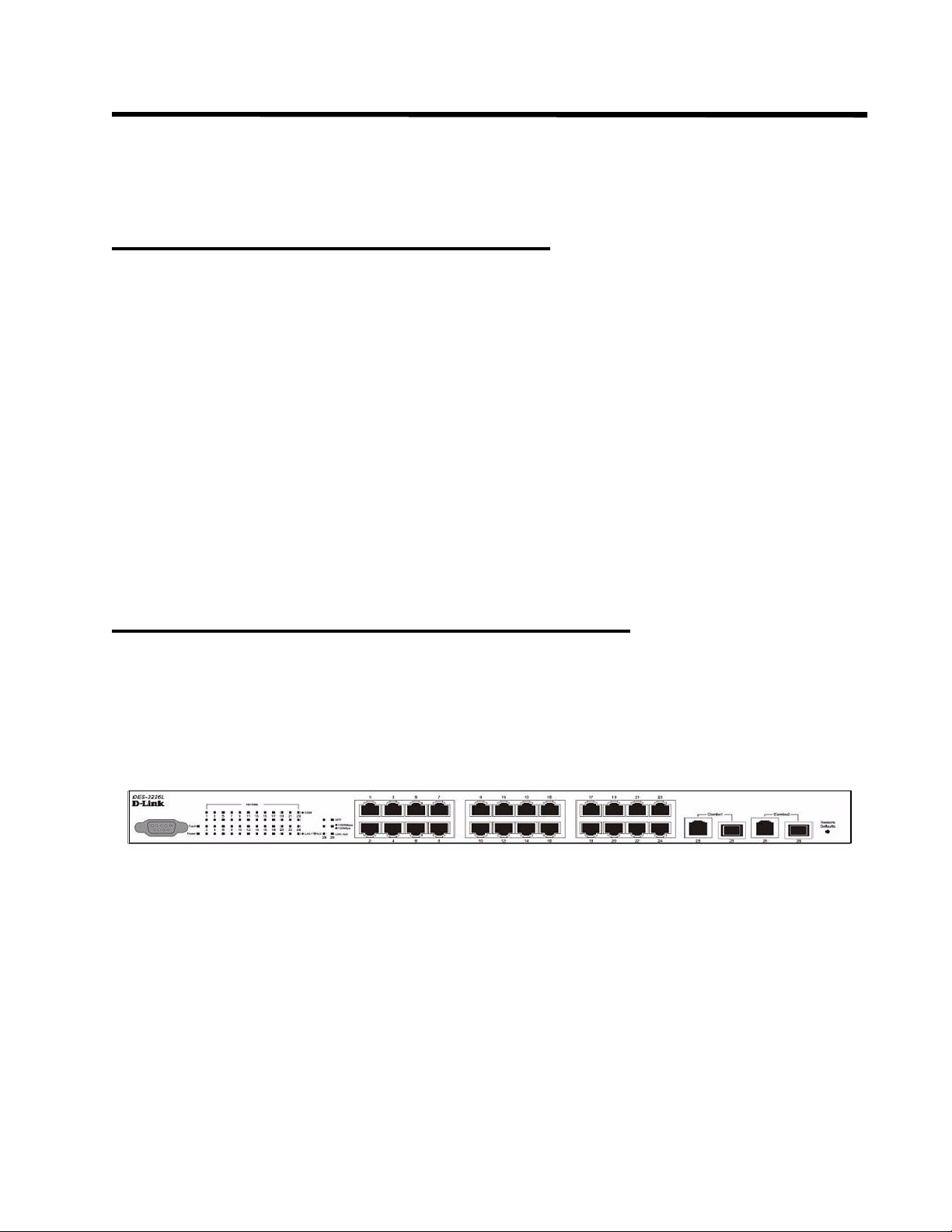
Installing the D-Link DES-3226L Switch
This section discusses installing the D-Link DES-3226L switch.
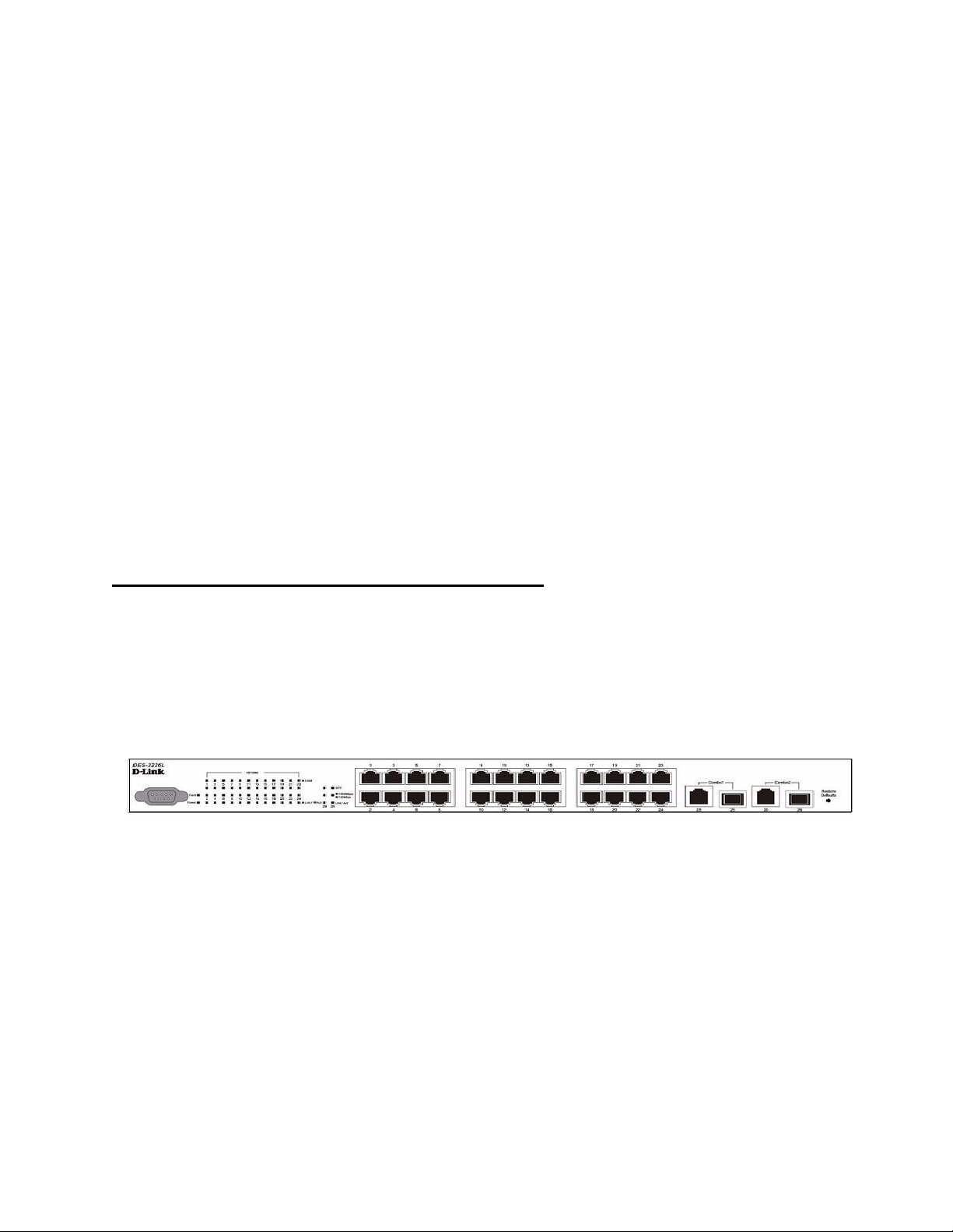
NOTE:
Figure 1. D-Link DES-3226L - Front View
Before unpacking the switch, inspect the container and report any evidence of damage.
Page 20

20 Web User Guide
Unpacking the Switch
1. Place the container on a clean flat surface and cut all straps securing the container.
2. Unpack the DES-3226L switch from the box. Save the packing material and box. Open the shipping carton of the switch and carefully unpack its contents. The carton should contain the following
items:
One DES-3226L stand-alone switch
One AC power cord
Rack mount kit (two brackets and screws)
Four rubber feet with adhesive backing
RS-232 console cable
Manual CD
NOTE:If any item is found missing or damaged, please contact your local D-Link Reseller
for replacement.
3. Carefully remove the switch from the container and place it on a secure and clean surface. See Section “Setting up the Switch.”
4. Remove all packing material.
5. Inspect the product and accessories for damage. Report any damage immediately.
Setting up the Switch
The site where you install the switch may greatly affect its performance. Please follow these
guidelines for setting up the switch.
z Install the switch on a sturdy, level surface that can support at least 6.6 lb. (3 kg) of
weight. Do not place heavy objects on the switch.
z Ensure that the power outlet is within 1.82 meters (6 feet) of the switch.
z Visually inspect the power cord and see that it is fully secured to the AC power port. See
Section “Connecting the Switch to a Power Supply.”
z Make sure that there is proper heat dissipation from and adequate ventilation around the
switch. Leave at least 10 cm (4 inches) of space at the front and rear of the switch for ventilation.
z Install the switch in a fairly cool and dry place for the acceptable temperature and humid-
ity operating ranges.
z Install the switch in a site free from strong electromagnetic field generators (such as
motors), vibration, dust, and direct exposure to sunlight.
z When installing the switch on a level surface, attach the rubber feet to the bottom of the
device. The rubber feet cushion the switch, protect the casing from scratches, and prevent
it from scratching other surfaces.
Connecting the Switch to a Power Supply
1. Connect one end of the AC power cable to the AC power connector located on the back panel (see
Figure 2) and the other end into the local power source outlet.
NOTE:Do not connect the power cable to a grounded AC outlet at this time. Connect the
switch to a power source as described in the step detailed in “Starting and Configuring the Switch” on page 23."
Page 21
NOTE:Read the safety information in the Product Information Guide as well as the safety
information for other switches that connect to or support the switch.
Figure 2. Connecting Power Cable
Connect a power cable to the DES-3226L.
2. After the switch is powered on, the LED indicators momentarily blink and then display solidly.
This blinking of the LED indicators represents a reset of the system.
Caution: CAUTION: As a precaution, in the event of a power failure, unplug the
switch. When power is resumed, plug the switch back into the wall outlet.
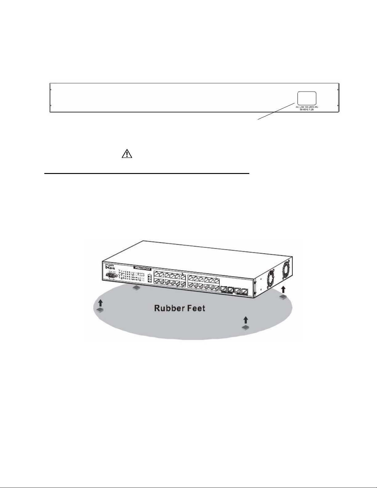
Installing on a Flat Surface (Free-standing Switch)
Install the switch on a flat surface if you are not installing it in a rack. The surface must be able
to support the weight of the switch and the switch cables.
Installing the Hardware 21
1. Attach the self-adhesive rubber pads on each location marked on the bottom of the chassis.
Figure 3. Prepare the Switch for Installation on a Desktop or Shelf
2. Set the switch on a flat surface, leaving 5.08 cm (2 inches) on each side and 12.7 cm (5 inches) at
the back.
3. Make sure that the switch has proper ventilation.
Page 22
22 Web User Guide
Installing in a Rack
The D-Link DES-3226L switch can be mounted in a standard 19” rack.
Caution:
CAUTION: Do not use rack mounting kits to suspend the switch from
under a table or desk or attach it to a wall.
Caution: CAUTION: Disconnect all cables from the switch before continuing.
Remove all self-adhesive pads from the underside of the switch if they have been
attached.
Caution: CAUTION: When mounting multiple switches into a rack, mount the
switches from the bottom up.
Caution: CAUTION: Make sure that the supplied rack bolts fit the pre-threaded
holes in the rack.
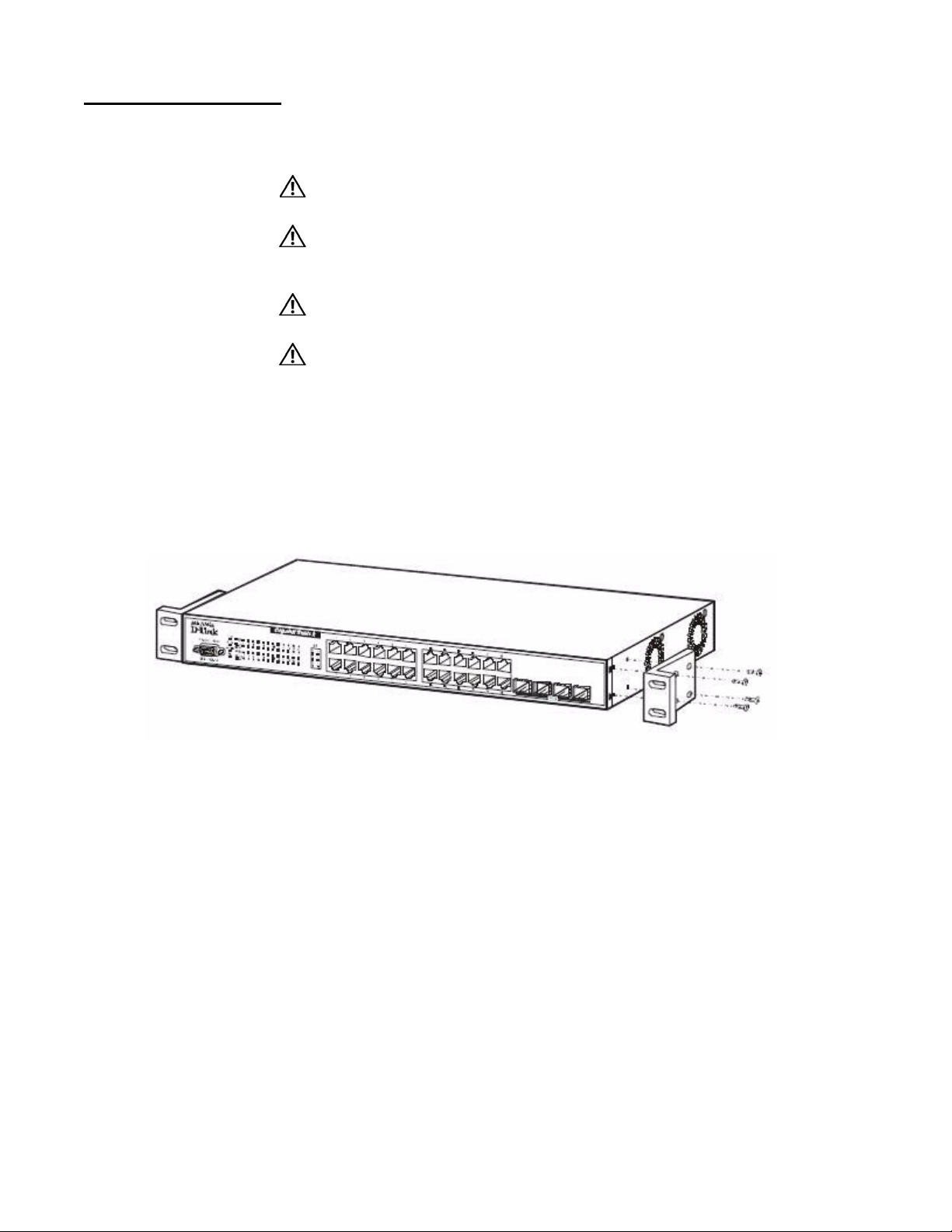
1. Place the supplied rack-mounting bracket on one side of the switch, ensuring that the mounting
holes on the switch line up to the mounting holes in the rack-mounting bracket. Figure 4 illustrates
where to mount the brackets.
Figure 4. Attaching the Brackets
Note: This figure is not an actual DES-3226L. It is used for explanatory purposes only.
2. Insert the supplied bolts into the rack-mounting holes and tighten with a screwdriver.
3. Repeat the process for the rack-mounting bracket on the other side of the switch.
4. Insert the switch into the 48.26 cm (19 inch) rack, ensuring that the rack-mounting holes on the
switch line up to the mounting holes in the rack.
Page 23
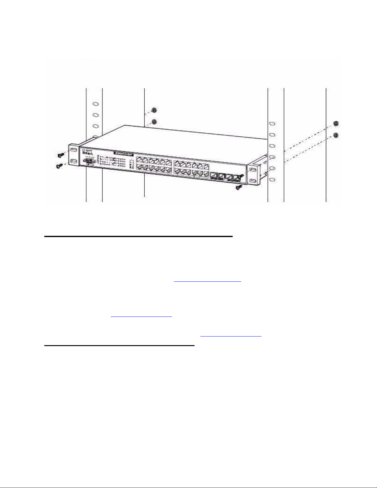
Installing the Hardware 23
Figure 5. Installing the DES-3226L in a Rack
Note: This figure is not an actual DES-3226L. It is used for explanatory purposes only.
5. Secure the switch to the rack with either the rack bolts or cage nuts and cage nut bolts with washers
(depending on the kind of rack you have). Fasten the bolts on bottom before fastening the bolts on
top. Make sure that the ventilation holes are not obstructed.
Starting and Configuring the Switch
After completing all external connections, connect a terminal to a switch to configure the
switch. Additional advanced functions are described in the DES-3226L CLI Guide or check
the D-Link Support web site at http://support.dlink.com/
documentation and software.
NOTE:
NOTE:We recommend that you obtain the most recent version of the user documentation
Configuring for In-band Connectivity
In-band connectivity allows you to access the D-Link DES-3226L from a remote workstation
using the Ethernet network. To use in-band connectivity, you must configure the DES-3226L
with IP information (IP address, subnet mask, and default gateway).
Read the release notes for this product before proceeding. You can download the
release notes from the D-Link Support website at
http://support.dlink.com/
from the D-Link Support website at http://support.dlink.com/
.
for the latest updates on
.
Configure for In-band connectivity using one of the following methods:
z BootP or DHCP
z RS-232 port
Page 24

24 Web User Guide
Using BootP or DHCP
You can assign IP information initially over the network or over the Ethernet service port
through BootP or DHCP. The DES-3226L has BootP enabled.
You need to configure the BootP or DHCP server with information about the DES-3226L —
obtain this information through the serial port connection using the
Set up the server with the following values:
IP Address
Unique IP address for the DES-3226L. Each IP parameter is made up of four decimal numbers,
ranging from 0 to 255. The default for all IP parameters is zeroes (0.0.0.0).
Subnet
Subnet mask for the LAN
gateway
IP address of the default router, if the switch is a node outside the IP range of the LAN
MAC Address
MAC address of the DES-3226L
show network command.
When you connect the DES-3226L to the network for the first time after setting up the BootP
or DHCP server, it is configured with the information supplied above. The DES-3226L is
ready for in-band connectivity over the network.
If you do not use BootP or DHCP, acces s the sw itch through the RS-232 port, and configure
the network information as described below.
Using the RS-232 Port
You can use a locally or remotely attached terminal to configure in-band management through
the RS-232 port.
1. To use a locally attached terminal, attach one end of a null-modem serial cable to the RS-232 port
of the switch and the other end to the COM port of the terminal or workstation.
For remote attachment, attach one end of the serial cable to the RS-232 port of the switch and the
other end to the modem.
NOTE:You must use the cable that was shipped with the D-Link DES-3226L.
2. Set up the terminal for VT100 terminal emulation.
A. Set the terminal ON.
B. Launch the VT100 appl ication.
C. Configure the COM port as follows:
I. Set the data rate to 115,200 baud.
II. Set the data form at to 8 data bits, 1 stop bit, and no parity.
III. Set the flow control to none.
IV. Select the proper mode under Properties.
V. Select Terminal keys.
3. The Log-in User prompt displays when the terminal interface initializes.
Enter an approved user name and password. The default is admin for the user name and the pass-
Page 25
Installing the Hardware 25
word is blank.
The DES-3226L is installed and loaded with the default configuration.
4. Reduce network traffic by turning off the Network Configuration Protocol. Enter the following
command:
configure network protocol none
5. Set the IP address, subnet mask, and gateway address by issue the following command:
config network parms ipaddress netmask gateway
IP Address
Unique IP address for the DES-3226L. Each IP parameter is made up of four decimal numbers,
ranging from 0 to 255. The default for all IP parameters is zeroes (0.0.0.0).
Subnet
Subnet mask for the LAN.
gateway
IP address of the default router, if the switch is a node outside the IP range of the LAN.
6. To enable these changes to be retained during a reset of the DES-3226L, type Ctrl-Z to return to
the main prompt, type save config at the main menu prompt, and type y to confirm the changes.
7. To view the changes and verify in-band information, issue the command: show network.
8. The DES-3226L is configured for in-band connectivity and ready for Web-based management.
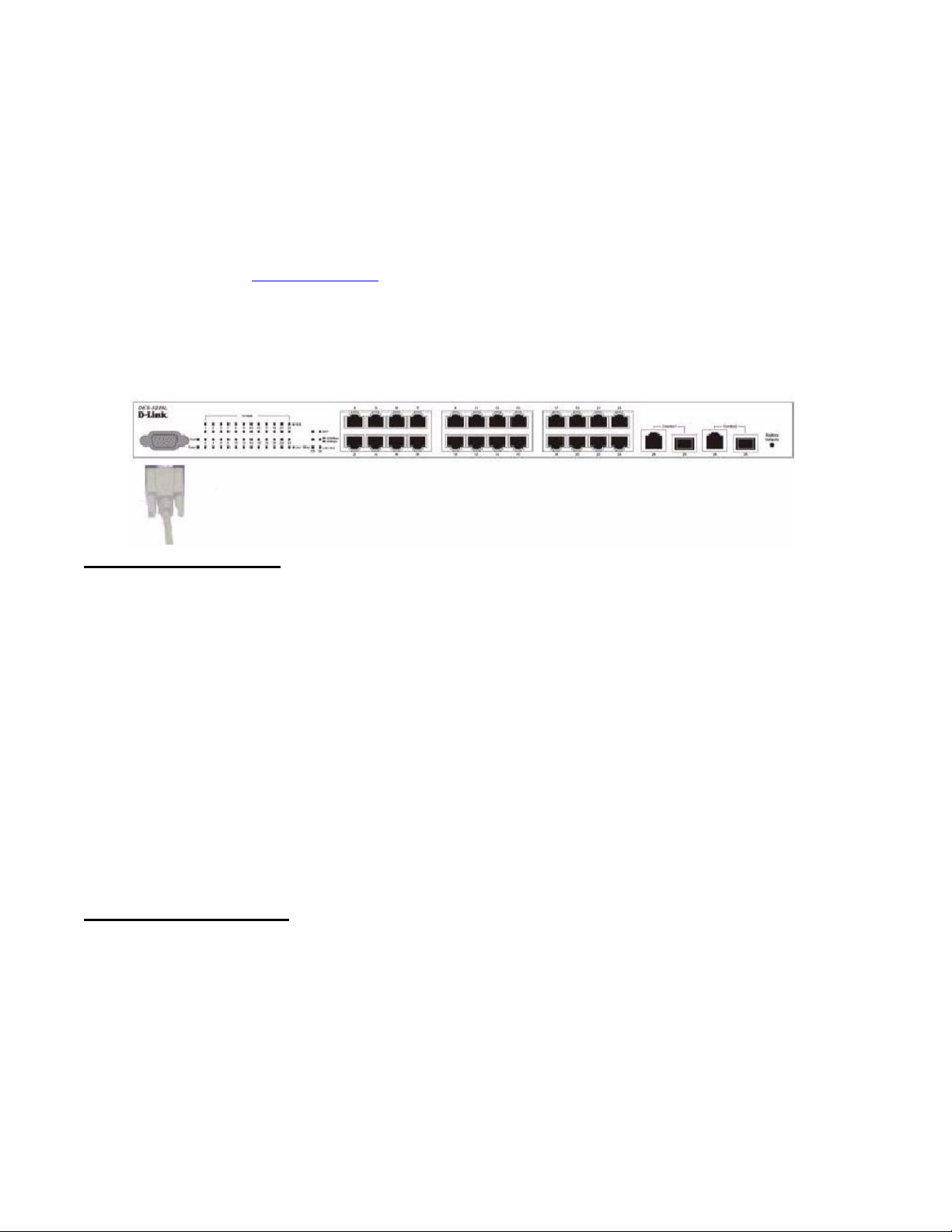
Configuring for Out-Of-Band Connectivity
To monitor and configure the switch using out-of-band connectivity, use the console port to
connect the switch to a terminal desktop system running terminal emulation software. The
console port connector is a male DB-9 connector, implemented as a data terminal equipment
(DTE) connector.
Figure 6. D-Link DES-3226L - Front View
The following hardware is required to use the console port:
z VT100-compatible terminal, or a desktop, or a portable system with a serial port running
VT100 terminal emulation software.
z An RS-232 crossover cable with a female DB-9 connector for the console port and the
appropriate connector for the terminal.
Perform the following tasks to connect a terminal to the switch console port using out-of-band
connectivity:
1. Connect an RS-232 crossover cable to the terminal running VT100 terminal emulation software.
2. Configure the terminal emulation software as follows:
A. Select the appropriate serial port (serial port 1 or serial port 2) to connect to the console.
B. Set the data rate to 115,200 baud.
Page 26
26 Web User Guide
NOTE:When using HyperTerminal with Microsoft Windows 2000, make sure that you have
3. Connect the female connector of the RS-232 crossover cable directly to the switch console port,
Figure 7. Connecting to the Console Port
C. Set the data format to 8 data bits, 1 stop bit, and no parity.
D. Set the flow control to none.
E. Select the proper mode under Properties.
F. Select Terminal keys.
Windows 2000 Service Pack 2 or later installed. With W indows 2000 Service Pack 2,
the arrow keys function properly in HyperTerminal's VT100 emulation. Go to
www.microsoft.com
and tighten the captive retaining screws. The DES-3226L series console port is located on the front
panel as shown in Figure 7.
for more information on Windows 2000 service packs.
Starting the Switch
1. Make sure that the switch console port is connected to a VT100 terminal or VT100 terminal emulator via the RS-232 crossover cable.
2. Locate an AC power receptacle.
3. Deactivate the AC power receptacle.
4. Connect the switch to the AC receptacle.
5. Activate the AC power receptacle.
When the power is turned on with the local terminal already connected, the switch goes
through a power-on self-test (POST). POST runs every time the switch is initialized and
checks hardware components to determine if the switch is fully operational before completely
booting. If POST detects a critical problem, the startup procedure stops. If POST passes
successfully, a valid executable image is loaded into RAM. POST messages are displayed on
the terminal and indicate test success or failure. The boot process runs for approximately 60
seconds.
Initial Configuration
The initial simple configuration procedure is based on the following assumptions:
z The DES-3226L switch was not configured before and is in the same state as when you
received it.
z The DES-3226L switch booted successfully.
z The console connection was established and the console prompt appears on the screen of a
VT100 terminal or terminal equivalent.
Page 27

Installing the Hardware 27
The initial switch configuration is performed through the console port. After the initial
configuration, you can manage the switch either from the already-connected console port or
remotely through an interface defined during the initial configuration.
NOTE:
The switch is not configured with a default user name and password.
NOTE:All of the settings below are necessary to allow the remote management of the switch
through Telnet (Telnet client) or HTTP (Web browser).
Before setting up the initial configuration of the switch, obtain the following information from
your network administrator:
z The IP address to be assigned to the management interface through which the switch is
managed.
z The IP subnet mask for the network.
z The IP address of the default gateway.
Initial Configuration Procedure
You can perform the initial configuration using the D-Link Easy Setup Wizard or by using the
Command Line Interface (CLI). The Setup Wizard automatically starts when the switch
configuration file is empty. You can exit the wizard at any point by entering [ctrl+z]. The
wizard sets up the following configuration on the switch:
z Establishes the initial privileged user account with a valid password. The wizard config-
ures one privileged user account during the set up.
z Enables CLI login and HTTP access to use the local authentication setting only.
z Sets up the IP address for the management interface.
z Sets up the SNMP community string to be used by the SNMP manager at a given IP
address. You may choose to skip this step if SNMP management is not used for this
switch.
z Allows you to specify the management server IP or permit SNMP access from all IP
addresses.
z Configures the default gateway IP address.
Example Session
This section describes an Easy Setup Wizard session. The following values are used by the
example session:
z IP address for the management interface is 192.168.1.100:255.255.255.0.
z The user name is admin, and no password is needed. Type in admin and press Enter.
z The network management system IP address is 192.168.1.10.
z The default gateway is 192.168.1.1.
The setup wizard configures the initial values as defined above. After you complete the
wizard, the system is configured as follows:
z SNMPv1/2c is enabled and the community string is set up as defined above. SNMPv3 is
disabled by default.
z The admin user account is set up as defined.
Page 28

28 Web User Guide
z A network management system is configured. From this management station, you can
z An IP address is configured for the default management interface (1).
z A default gateway address is configured.
access the SNMP, HTTP, and CLI interfaces. You may also choose to allow all IP
addresses to access these management interfaces by choosing the (0.0.0.0) IP address.
NOTE:
In the example below , the possible user options are enclosed in [ ]. Also, where possible, the default value is provided in { }. If you enter <Return> with no options
defined, the default value is accepted. Help text is in parentheses.
The following example contains the sequence of prompts and responses associated with
running an example D-Link Easy Setup Wizard session, using the input values listed above.
After the switch completes the POST and is booted, the following dialog appears:
U-Boot 0.3.0 (Sep 23 2005 - 14:05:10)
Board: DLink DES-3226L
DRAM: Less than 128MB hence resetting to try 64MB
U-Boot 0.3.0 (Sep 23 2005 - 14:05:10)
Board: DLink DES-3226L
DRAM: 64 MB
Flash: 8 MB
In: serial
Out: serial
Err: serial
Hit any key to stop autoboot: 0
0
## Booting image at a0400000 ...
Image Name: Linux 2.4.20
Image Type: MIPS Linux Multi-File Image (gzip compressed)
Data Size: 1876253 Bytes = 1.8 MB
Load Address: 80001000
Entry Point: 80196048
Contents:
Verifying Checksum ... OK
Uncompressing Multi-File Image ... OK
Starting kernel ...
Broadcom BCM947XX Startup Rev: 1.3
Select startup mode. If no selection is made within 3 seconds,
the Broadcom BCM947XX Application will start automatically...
1 - Start Broadcom BCM947XX Application
2 - Display Utility Menu
Select (1, 2):
Starting Broadcom BCM947XX application...
Console starting...\
SPI unit 0: Dev 0xbc20, Rev 0x01, Chip BCM5324_A1, Driver BCM5324_A1
PCI unit 1: Dev 0x4713, Rev 0x09, Chip BCM4713_A0, Driver BCM4713_A0
SPI device BCM5324_A1 attached as unit 0.
-/enable_irq(4) unbalanced from c007b7a0
Broadcom BCM47xx 10/100 Mbps Ethernet Controller 2002.9.27.0
started!
(Unit 1)>
User:
Page 29

LED Indicators
The following table explains what the various LEDs on the switch represent when they light
up.
Table 4. LED Indicators
Power LED The indicator lights solid green when the switch is receiving
Fault state LED • The light blinks green on start-up (post).
Per port Speed/Link/Activity
state LED
Installing the Hardware 29
LED Description
power; otherwise, the light is off.
• The light turns off while the system is running.
• The light turns on solid green if a u-boot permanent fault occurs.
• Link/Act LED: The indicators light up when there is a secure
connection (or link) to an Ethernet device per port. The
indicator blinks whenever there is reception or transmission
(that is, Activity/Act) per port.
• Speed LED:
- When 10/100Mbps per port, the indicator light is:
Green when linked to 100Mbps.
Off when linked to 10Mbps.
- When 10/100/1000Mbps per port, the indicator light is:
Yellow when linked to 100Mbps.
Light green when linked to 1000Mbps.
Off when linked to 10Mbps.
• SFP LED: The indicator lights green when linked to a SFP
interface.
Page 30

30 Web User Guide
Page 31

Software Installation
This section contains procedures to help you become acquainted quickly with the D-Link
DES-3226L switch software.
Upgrading the Switch Firmware
Use the information in this section to upgrade the D-Link DES-3226L firmware to the latest
version. Follow these instructions to upgrade:
1. Open your web browser to the D-Link support website:
http://support.dlink.com/
2. Select your D-Link product from the drop-down: DES 3226L
3. Click Go.
4. The D-Link Switches Product Description web page appears.
5. Scroll down to the section of this web page where the Firmware tab is disp layed. An example of
this tab is displayed in Figure 8.
Software Installation 31
NOTE:Figure 8 is only an example. This website is updated for new firmware releases.
Figure 8. Firmware Download for D- Link DES-3226L
6. Select Download Now for the latest version of firmwa re to beg in your download.
7. Click OK on the next warning screen.
8. Click Run to run the upgrade from the D-Link site.
Page 32

32 Web User Guide
Quick Starting the Networking Device
NOTE:Before you use the information in this section, ensure that you have upgraded to the
latest firmware. See “Upgrading the Switch Firmware” on page 31.
1. Read “Installing the Hardware” on page 19 for the connectivity procedure. In-band connectivity
allows access to the D-Link software locally or from a remote workstation. You must configure the
device with IP information (IP address, subnet mask, and default gateway).
2. Turn the Power ON.
3. Allow the device to load the software until the login prompt appears. The device initial state is
called the default mode.
4. When the prompt asks for operator login, do the following steps:
Type admin at the login prompt. Since a number of the Quick Setup commands
require administrator account rights, D-Link suggests logging into an administrator
account.
Do not enter a password because the default mode does not use a password.
The CLI User EXEC prompt is displayed.
Enter enable to switch to the Privileged EXEC mode from User EXEC.
Enter configure to switch to the Global Config mode from Privileged EXEC.
Enter exit to return to the previous mode.
Enter ? to show a list of commands that are available in the current mode.
System Information and System Setup
This section describes the commands you use to view system information and to setup the
network device. Table 5 contains the Quick Start commands that allow you to view or
configure the following information:
z Software versions
z Physical port data
z User account management
z IP address configuration
z Uploading from Networking Device to Out-of-Band PC (Only XMODEM)
z Downloading from Out-of-Band PC to Networking Device (Only XMODEM)
z Downloading from TFTP Server
z Restoring factory defaults
If you configure any network parameters, you should execu te the following command:
copy system:running-config nvram:startup-config
This command saves the changes to the configuration file. Y ou must be in the correct mode to
execute the command. If you do not save the configuration, all changes are lost when a you
power down or reset the networking device.
Page 33

Software Installation 33
T able 5 describes the c ommand s yntax, the m ode you mu st be in to execute th e comman d, and
the purpose and output of the command.
Table 5. Quick Start Commands
Command Mode Description
show hardware Privileged
EXEC
show users Privileged
EXEC
show
loginsession
users passwd
<username>
copy system:runningconfig
nvram:startupconfig
logout User EXEC
User EXEC Displays all of the login session information.
Global Config Allows the user to set passwords or change passwords
Privileged
EXEC
Privileged
EXEC
Shows hardware version, MAC address, and software version information.
Displays all of the users that are allowed to access the networking device.
Access Mode shows whether the user is able to change
parameters on the networking device (Read/Write) or is
only able to view them (Read Only).
As a factory default, the ‘admin’ user has Read/Write
access and the ‘guest’ user has Read Only access. There
can only be one Read/Write user and up to five Read Only
users.
needed to login.
A prompt appears after the command is entered requesting
the users old password. In the absence of an old password
leave the area blank.
User password should not be more than eight characters in
length.
Saves passwords and all other changes to the device.
If you do not save the configuration, all changes are lost
when you power down or reset the networking device.
Logs the user out of the networking device.
Page 34

34 Web User Guide
Table 5. Quick Start Commands
show network User EXEC Di splays the following network configuration informa-
network parms
<ipaddr> <netmask> [gateway]
copy
nvram:startupconfig
<ipaddress>/
<filepath>/
<filename>>
copy
nvram:errorlog
<tftp://<ipaddress>/<filepath>/
<filename>>
Command Mode Description
tion:
• IP Address - IP Address of the interface (default:
0.0.0.0)
• Subnet Mask - IP Subnet Mask for the interface (default:
0.0.0.0)
• Default Gateway - The default Gate way for this interface (default: 0.0.0.0)
• Burned in MAC Address - The Burned in MAC Address
used for in-band connectivity
• Locally Administered MAC Address - Can be configured to allow a locally administered MAC address
• MAC Address Type - Specifies which MAC address
should be used for in-band connectivity
• Network Configurations Protocol Current - Indicates
which network protocol is being used (default: none)
• Management VLAN Id - Specifies VLAN id
• Web Mode - Indicates whether HTTP/Web is enabled.
• Java Mode - Indicates whether java mode is enabled.
Privileged
EXEC
Sets the IP address, subnet mask and gateway of the
router. The IP address and the gateway must be on the
same subnet. IP address range is from 0.0.0.0 to
255.255.255.255.
Privileged
EXEC
<tftp://
Starts the configuration file upload, displays the mode and
type of upload and confirms the upload is progressing.
The URL must be specified as:
xmodem:<filepath>/<filename>
For example:
If the user is using HyperTerminal, the user must specify
where the file is going to be received by the PC.
Privileged
EXEC
Starts the error log upload, displays the mode and type of
upload and confirms the upload is progressing.
The URL must be specified as:
xmodem:<filepath>/<filename>
copy nvram:traplog
<tftp://
<ipaddress>/
<filepath>/
<filename>>
Privileged
EXEC
Starts the trap log upload, displays the mode and type of
upload and confirms the upload is progressing.
The URL must be specified as:
xmodem:<filepath>/<filename>
Page 35

Table 5. Quick Start Commands
Command Mode Description
copy <tftp://
<ipaddress>/
<filepath>/
<filename>>
nvram:startupconfig
Privileged
EXEC
Sets the destination (download) datatype to be an image
(system:image) or a configuration file (nvram:startup-config).
The URL must be specified as:
xmodem:<filepath>/<filename>
For example:
If the user is using Hyper Terminal, the user must specify
which file is to be sent to the networking device.
The Networking Device restarts automatically once the
code has been downloaded.
copy
<ipaddress>/
<filepath>/
<filename>>
<tftp://
sys-
tem:image
copy
<ipaddress>/
<filepath>/
<filename>>
<tftp://
nvram:startupconfig
Privileged
EXEC
Privileged
EXEC
Sets the destination (download) datatype to be an image
(system:image) or a configuration file (nvram:startup-config).
The URL must be specified as:
xmodem:<filepath>/<filename>
Sets the destination (download) datatype to be a configu-
ration file.
The URL must be specified as:
tftp://<ipaddress>/<filepath>/<filename>
Before starting a TFTP server download, you must config-
ure the IP address.
copy
<ipaddress>/
<filepath>/
<filename>>
<tftp://
sys-
tem:image
clear config Privileged
copy system:running-
Privileged
EXEC
EXEC
Privileged
EXEC
Sets the destination (download) datatype to be an image.
The URL must be specified as:
tftp://<ipaddress>/<filepath>/<filename>
The system:image option downloads the code file.
Enter yes when the prompt pops up to clear all the config-
urations made to the networking device.
Enter yes when the prompt pops up that asks if you want
to save the configurations made to the networking device.
config
nvram:startupconfig
reload (or cold boot
the networking
device)
Privileged
EXEC
Enter yes when the prompt pops up that asks if you want
to reset the system.
You can reset the networking device or cold boot the networking device, both work effectively.
Software Installation 35
Page 36

36 Web User Guide
Page 37

Using the Web Interface
This chapter is a brief introduction to the web interface.
Tip: Use the Web interface for configuration instead of the CLI interface. Web configuration
is quicker and easier than entering the multiple required CLI commands.
You can manage your switch through a Web browser and Internet connection. This is referred
to as W eb-based management. To use Web-based management, the DES-3226L must be set up
for in-band connectivity.
To access the switch, the Web browser must support:
z HTML version 4.0, or later
z HTTP version 1.1, or later
z JavaScript
This section explains how to access the switch Web-based management panels to configure
and manage the switch.
Note that there are equivalent functions in the Web interface as in the terminal interface —
that is, both applications usually employ the same menus to accomplish a task. For example,
when you log in, there is a Main Menu with the same functions available, etc.
(TM)
version 1.2, or later
Using the Web Interface 37
There are several differences between the Web and terminal interfaces. For example, on the
Web interface the entire forwarding database can be displayed, while the terminal interface
only displays 10 entries starting at specified addresses.
To terminate the Web login session, close the web browser.
Configuring for Web Access
To enable Web access to the switch:
1. Configure the switch for in-band connectivity. See “Configuring for In-band Connectivity” on
page 23 for instructions.
2. Enable Web mode:
A. At the CLI prompt, enter the show network
B. Set Web Mode to Enabled.
command.
Page 38

38 Web User Guide
Web Page Layout
A Web interface panel for the switch Web page consists of three areas (Figure 9).
A banner graphic of the switch appears across the top of the panel.
The second area, a hierarchical-tree view appears to the left of the panel. The tree consists of a
combination of folders, subfolders, and configuration and status HTML pages. You can think
of the folders and subfolders as branches and the configuration and status HTML pages as
leafs. Only the selection of a leaf (not a folder or subfolder) will cause the display of a new
HTML page. A folder or subfolder has no corresponding HTML page.
The third area, at the bottom-right of the panel, displays the currently selected device
configuration status and/or the user configurable information that you have selected from the
tree view.
Figure 9. Web Interface Panel-Example
Page 39

Starting the Web Interface
Follow these steps to start the switch DES-3226L Web interface:
1. Enter the IP address of the switch in the Web browser address field.
2. When the Login panel is displaye d, click Login, then enter the appropriate User Name and Password. The User Name and associated Password are the same as those used for the terminal interface. Click on the Login button. The System Description Menu displays as shown in Figure 9, with
the navigation tree appearing to the left of the screen.
3. Make a selection by clicking on the appropriate item in the navigation tree.
4. Configuring an SNMP V3 User Profile
Configuring an SNMP V3 user profile is a part of user configuration. Any user can connect to
the D-Link DES-3226L switch using the SNMPv3 protocol, but for authentication and
encryption, additional steps are needed. Use the following steps to configure an SNMP V3
new user profile.
1. Select System>Configuration>User Accounts from the hierarchical tree on the left side of the
web interface (see Figure 10).
Figure 10. Configuring an SNMP V3 User Profile
Using the Web Interface 39
2. Using the User pulldown menu, select Create to create a new user.
3. Enter a new user name in the User Name field.
4. Enter a new user password in the Password field and then retype it in the Confirm Password field.
Page 40

40 Web User Guide
NOTE: If SNMPv3 Authentication is to be used for this user, the password must be eight or
more alphanumeric characters.
5. If you do not need authentication, go to Step 9.
6. To enable authentication, use the Authentication Protocol pulldown menu to select either MD5 or
SHA for the authentication protocol.
7. If you do not need encryption, go to Step 9.
8. To enable encryption, use the Encryption Protocol pulldown menu to select DES for the encryp-
tion scheme. Then, enter in the Encryption Key field an encryption code of eight or more alphanumeric characters.
9. Click Submit.
Command Buttons
The following command buttons are used throughout the Web interface panels for the switch:
Save Pressing the Save button implements and saves the changes you just made. Some set-
Refresh Pressing the Refresh button that appears next to the Apply button in Web interface
tings may require you to reset the system in order for them to take effect.
panels refreshes the data on the panel.
Submit Pressing the Submit button sends the updated configuration to the switch. Configura-
tion changes take effect immediately, but these changes are not retained across a
power cycle unless a save is performed.
Page 41

IGMP Snooping
This section describes the Internet Group Management Protocol (IGMP) feature: IGMPv3 and
IGMP Snooping.
Overview
IGMP:
z Uses Version 3 of IGMP
z Includes snooping
z Snooping can be enabled per VLAN
CLI Examples
IGMP Snooping 41
The following are examples of the commands used in the IGMP Snooping feature.
Example #1: show igmpsnooping
(Console) #show igmpsnooping?
<cr> Press Enter to execute the command.
<slot/port> Enter interface in slot/port format.
mrouter Display IGMP Snooping Multicast Router information.
<1-4093> Display IGMP Snooping valid VLAN ID information.
(Console) #show igmpsnooping
Admin Mode...............................Enable
Multicast Control Frame Count............0
Interfaces Enabled for IGMP Snooping.....0/10
Vlans enabled for IGMP snooping..........20
Example #2: show mac-address-table igmpsnooping
(Console) #show ip igmp interface?
MAC Address TypeDescriptionInterfaces
----------------------- --------------------------------
00:01:01:00:5E:00:01:16 DynamicNetwork AssistFwd: 0/47
00:01:01:00:5E:00:01:18 DynamicNetwork AssistFwd: 0/47
00:01:01:00:5E:37:96:D0 DynamicNetwork AssistFwd: 0/47
00:01:01:00:5E:7F:FF:FA DynamicNetwork AssistFwd: 0/47
00:01:01:00:5E:7F:FF:FE DynamicNetwork AssistFwd: 0/47
Page 42

42 Web User Guide
Web Examples
The following web pages are used in the IGMP Snooping feature. Click Help for more
information on the web interface.
Figure 11. IGMP Snooping - Global Configuration and Status Page
Page 43

Figure 12. IGMP Snooping - Interface Configuration Page
IGMP Snooping 43
Figure 13. IGMP Snooping - VLAN Status Page
Page 44

44 Web User Guide
Page 45

Configuration Scripting
This section describes the Configuration Scripting feature.
Overview
Configuration Scripting:
z Allows you to generate text-formatted files
z Provides scripts that can be uploaded and downloaded to the system
z Provides flexibility to create command configuration scripts
z May be applied to several switches
z Can save up to ten scripts or 500K of memory
z Provides List, Delete, Apply, Upload, Download
z Provides script format of one CLI command per line
Configuration Scripting 45
Considerations
z Total number of scripts stored on box limited by NVRAM/FLASH size.
z Application of scripts is partial if script fails. For example, if the script executes five of ten
commands and the script fails, the script stops at five.
z Scripts cannot be modified or deleted while being applied.
z Validation of scripts checks for syntax errors only. It does not validate that the script will
run.
CLI Examples
The following are examples of the commands used for the Configuration Scripting feature.
Example #1: script
(Console) #script ?
apply Applies configuration script to the switch.
delete Deletes a configuration script file from the switch.
list Lists all configuration script files present on the
show Displays the contents of configuration script.
validate Validate the commands of configuration script.
switch.
Page 46

46 Web User Guide
Example #2: script list and script delete
(Console) #script list
Configuration Script Name Size(Bytes)
------------------------- ----------basic.scr 93
running-config.scr 3201
2 configuration script(s) found.
1020706 bytes free.
(Console) #script delete basic.scr
Are you sure you want to delete the configuration script(s)? (y/n) y
1 configuration script(s) deleted.
Example #3: script apply running-config.scr
(Console) #script apply running-config.scr
Are you sure you want to apply the configuration script? (y/n) y
The systems has unsaved changes.
Would you like to save them now? (y/n) y
Configuration Saved!
Example #4: Creating a Configuration Script
(Console) #show running-config running-config.scr
Config script created successfully.
(Console) #script list
Configuration Script Name Size(Bytes)
------------------------- ---------running-config.scr 3201
1 configuration script(s) found.
1020799 bytes free.
Page 47

Example #5: Upload a Configuration Script
(Console) #copy nvram: script running-config.scr
tftp://192.168.77.52/running-config.scr
Mode......................... TFTP
Set TFTP Server IP........... 192.168.77.52
TFTP Path.................... ./
TFTP Filename................ running-config.scr
Data Type.................... Config Script
Source Filename.............. running-config.scr
Are you sure you want to start? (y/n) y
File transfer operation completed successfully.
Example #6: script validate running-config.scr
(Console) #script validate running-config.scr
network protocol dhcp
no network javamode
vlan database
exit
configure
stack
member 2 1
exit
logging buffered
logging host 192.168.77.151
Configuration Scripting 47
Configuration script ‘running-config.scr’ validated.
(Console) #script apply running-config.scr
Are you sure you want to apply the configuration script? (y/n) y
The system has unsaved changes.
Would you like to save them now? (y/n) y
Configuration Saved!
Page 48

48 Web User Guide
Example #7: Validate another Configuration Script
(Console) #script validate default.scr
network parms 172.30.4.2 255.255.255.0 0.0.0.0
vlan database
exit
configure
lineconfig
exit
spanning-tree configuration name 00-18-00-00-00-10
interface 0/1
exit
interface 0/2
exit
interface 0/3
exit
... continues through interface 0/26 ...
exit
exit
Configuration script 'default.scr' validation succeeded.
Page 49

Port Mirroring
This section describes the Port Mirroring feature.
Overview
Port Mirroring:
z Allows you to monitor network traffic with an external network analyzer
z Forwards a copy of each incoming and outgoing packet to a specific port
z Is used as a diagnostic tool, debugging feature or means of fending off attacks
z Assigns a specific port to copy all packets to
z Allows inbound or outbound packets to switch to their destination and to be copied to the
mirrored port
CLI Examples
Port Mirroring 49
The following are examples of the commands used in the Port Mirroring feature.
Example #1: show monitor session
(Console) #show monitor session 1
Session ID Admin Mode Probe Port Mirrored Port
---------- ---------- ---------- -------------
1 Enable 0/5 0/4
NOTE:
Monitor session ID “1” - “1” is a hardware limitation.
Example #2: show port all
(Console) #show port all
Admin PhysicalPhysicalLink Link LACP
Intf Type Mode Mode StatusStatus Trap Mode
---- ---- ------ ---------------------- ---- ----
0/1 Enable Auto Down Enable Enable
0/2 Enable Auto Down Enable Enable
0/3 Enable Auto Down Enable Enable
0/4 Mirror Enable Auto Down Enable Enable
0/5 Probe Enable Auto Down Enable Enable
0/6 Enable Auto Down Enable Enable
0/7 Enable Auto Down Enable Enable
0/8 Enable Auto Down Enable Enable
0/10 Enable Auto Down Enable Enable
Page 50

50 Web User Guide
Example #3: show port interface
Use this command for a specific port. The output shows whether the port is the mirror or the
probe port, what is enabled or disable on the port, etc.
(Console) #show port 0/4
Admin Physical PhysicalLink Link LACP
Intf Type Mode Mode Status Trap Mode
---- ---- ------ -------- -------------- ---- ---0/4 Mirror Enable Auto Down Enable Enable
(Console) #show port 0/5
Admin Physical PhysicalLink Link LACP
Intf Type Mode Mode Status Trap Mode
---- ---- ------ -------- -------------- ---- ---0/5 Probe Enable Auto Down Enable Enable
Example #4: show monitor session 1
(Console) #show monitor session 1?
<cr> Press Enter to execute the command.
(Console) #show monitor session 1
Session ID Admin Mode Probe Port Mirrored Port
---------- ---------- ---------- ------------1 Enable 0/5 0/4
Example #5: (Config) monitor session 1 mode
To set up port mirroring, specify the monitor session, then the mode.
(Console)(Config) #monitor?
session Configure port mirroring.
(Console)(Config) #monitor session?
<1-1> Session number.
(Console)(Config) #monitor session 1?
destination Configure the probe interface.
mode Enable/Disable port mirroring session.
source Configure the source interface.
(Console)(Config) #monitor session 1 mode?
<cr> Press Enter to execute the command.
(Console)(Config) #monitor session 1 mode
Page 51

Example #6: (Config) monitor session 1 source interface
Specify the source ports and destination port.
(Console)(Config) #monitor session 1 source?
interface Configure interface.
(Console)(Config) #monitor session 1 source interface?
<slot/port> Enter the interface.
(Console)(Config) #monitor session 1 source interface 0/4
(Console)(Config) #monitor session 1 destination?
interface Configure interface.
(Console)(Config) #monitor session 1 destination interface?
<slot/port> Enter the interface.
(Console)(Config) #monitor session 1 destination interface 0/5
Web Examples
Port Mirroring 51
The following web pages are used with the Port Mirroring feature.
Figure 14. System - Port Summary
Page 52

52 Web User Guide
Figure 15. System - Port - Multiple Port Mirroring
Page 53

Syslog
Overview
Persistent Log Files
Syslog 53
This section provides information about the Syslog feature.
Syslog:
• Allows you to store system messages and/or errors
• Can store to local files on the switch or a remote server running a syslog daemon
• Method of collecting message logs from many systems
• Currently three - one for each of the last three sessions
• Each log has two parts:
- Start up log is the first 32 messages after system startup
- Operational log is the last 32 messages received after the startup log is full
• Files are stored in ASCII format
- slog0.txt - slog2.txt
- olog0.txt - olog2.txt
Where 0 is for the boot, 1 is for the last boot, 2 is for the boot before that, and the third one
falls off.
• Can be saved to local server to monitor at a later point in time
Interpreting Log Files
<130> JAN 01 00:00:06 0.0.0.0-1 UNKN [0x800023]: bootos.c(386) 4 %% Event (0xaaaaaaaa)
AB
A. Priority
B. Timestamp
C. Stack ID
D. Component Name
E. Thread ID
F. File Name
G. Line Number
H Sequence Number
I. Message
C
DEF GH I
Page 54

54 Web User Guide
CLI Examples
The following are examples of the commands used in the Syslog feature.
Example #1: show logging
(Console) #show logging
Logging Client Local Port :514
CLI Command Logging :disabled
Persistent Logging :enabled
Persistent Logging Severity Filter :alert
Syslog Logging :disabled
Log Messages Received :66
Log Messages Dropped :0
Log Messages Relayed :0
Log Messages Ignored :0
Example #2: show logging persistent
(Console) #show logging persistent
Persistent Logging :enabled
Persistent Logging Severity Filter :alert
Persistent Log Count :2
<6> Jan 1 00:00:20 STK1 BOOT[83]: bootos.c(307) 0 %% Starting code...
<6> Jan 1 00:00:20 STK1 BOOT[83]: bootos.c(308) 1 %% rc = 10
Example #3: show logging traplogs
(Console) #show logging traplogs?
<cr> Press Enter to execute the command.
(Console) #show logging traplogs
Number of Traps Since Last Reset......... 6
Trap Log Capacity........................256
Number of Traps Since Log Last Viewed.... 6
Log System Up Time Trap
--- -------------- --------------------------------------0 0 days 05:52:59 Multiple Users: Unit: 1 Slot: 3 Port: 1
1 0 days 05:04:15 Multiple Users: Unit: 1 Slot: 3 Port: 1
2 0 days 00:00:54 Cold Start: Unit: 0
3 0 days 00:00:36 Link Up: Unit: 1 Slot: 0 Port: 1
Page 55

Example #4: logging port configuration
(Console) #config
(Console) (Config)# logging ?
cli-command CLI Command Logging Configuration.
host Enter IP Address for Logging Host
persistent Logging Persistent Configuration.
syslog Syslog Configuration.
(Console) (Config)# logging host ?
<hostaddress> Enter Logging Host IP Address
reconfigure Logging Host Reconfiguration
remove Logging Host Removal
(Console) (Config)# logging host ?
<cr> Press Enter to execute the command.
<port> Enter Port Id
(Console) (Config)# logging host 10.254.24.153 4 ?
<cr> Press Enter to execute the command.
<severitylevel> Enter Logging Severity Level (emergency|0, alert|1,
critical|2, error|3, warning|4, notice|5, info|6,
debug|7).
Syslog 55
(Console) (Config)# logging host 10.254.24.153 4 1 ?
<cr> Press Enter to execute the command.
(Console) (Config)# logging host 10.254.24.153 4 1
(Console) (Config)# exit
(Console) (Config)#exit
Example #5: show logging hosts
(Console) #show logging hosts ?
<cr> Press Enter to execute the command.
(Console) #show logging hosts
Index IP Address Severity Port Status
----- ----------------- ---------- ---- ------------1 10.254.24.153 warning 7 Active
Page 56

56 Web User Guide
Web Examples
The following web pages are used in the Syslog feature.
Figure 16. Persistent Log Configuration Page
Figure 17. Persistent Logs
Page 57

Traceroute
This section describes the Traceroute feature.
Traceroute Overview
Use Traceroute to discover the routes that packets take when traveling on a hop-by-hop basis
to their destination through the network.
z Maps network routes by sending packets with small Time-to-Live (TTL) values and
watches the ICMP time-out announcements
z Command displays all L3 devices
z Can be used to detect issues on the network
z Tracks up to 20 hops
z Default UPD port used 33343 unless modified in the traceroute command
NOTE: You can execute Traceroute with CLI commands only — there is no Web
interface for this feature.
Traceroute 57
CLI Example
The following shows an example of using the traceroute command to determine how many
hops there are to the destination.
The command output shows each IP address the packet passes through and how long it takes
to get there. In this example, the packet takes 13 hops to reach its destination.
(Console) #traceroute?
<ipaddr> Enter IP address.
(Console) #traceroute 216.109.118.74 ?
<cr> Press Enter to execute the command.
<port> Enter port no.
(Console) #traceroute 216.109.118.74
Tracing route over a maximum of 20 hops
1 10.254.24.1 40 ms 9 ms 10 ms
2 10.254.253.1 30 ms 49 ms 21 ms
3 63.237.23.33 29 ms 10 ms 10 ms
4 63.144.4.1 39 ms 63 ms 67 ms
5 63.144.1.141 70 ms 50 ms 50 ms
6 205.171.21.89 39 ms 70 ms 50 ms
7 205.171.8.154 70 ms 50 ms 70 ms
8 205.171.8.222 70 ms 50 ms 80 ms
9 205.171.251.34 60 ms 90 ms 50 ms
10 209.244.219.181 60 ms 70 ms 70 ms
11 209.244.11.9 60 ms 60 ms 50 ms
12 4.68.121.146 50 ms 70 ms 60 ms
13 4.79.228.2 60 ms 60 ms 60 ms
14 216.115.96.185 110 ms 59 ms 70 ms
15 216.109.120.203 70 ms 66 ms 95 ms
16 216.109.118.74 78 ms 121 ms 69 ms
Page 58

58 Web User Guide
Page 59

Virtual LANs
Adding Virtual LAN (VLAN) support to a Layer 2 switch offers some of the benefits of both
bridging and routing. Like a bridge, a VLAN switch forwards traffic based on the Layer 2
header, which is fast, and like a router, it partitions the network into logical segments, which
provides better administration, security and management of multicast traffic.
A VLAN is a set of end stations and the switch ports that connect them. You may have many
reasons for the logical division, such as department or project membership. The only physical
requirement is that the end station and the port to which it is connected both belong to the
same VLAN.
Each VLAN in a network has an associated VLAN ID, which appears in the IEEE 802.1Q tag
in the Layer 2 header of packets transmitted on a VLAN. An end station may omit the tag, or
the VLAN portion of the tag, in which case the first switch port to receive the packet may
either reject it or insert a tag using its default VLAN ID. A given port may handle traffic for
more than one VLAN, but it can only support one default VLAN ID.
The Private Edge VLAN feature lets you set protection between ports located on the switch.
This means that a protected port cannot forward traffic to another protected port on the same
switch.
Virtual LANs 59
The feature does not provide protection between ports located on different switches.
VLAN Configuration Example
The diagram in this section shows a switch with four ports configured to handle the traffic for
two VLANs. Port 0/2 handles traffic for both VLANs, while port 0/1 is a member of VLAN 2
only, and ports 0/3 and 0/4 are members of VLAN 3 only. The script following the diagram
shows the commands you would use to configure the switch as shown in the diagram.
Page 60

60 Web User Guide
Figure 18. VLAN example network diagram
Layer 2 Switch
CLI Examples
The following examples show how to c reate V LANs, assign ports to the VLANs, and assign a
VLAN as the default VLAN to a port.
Example #1: Create Two VLANs
Use the following commands to create two VLANs and to assign the VLAN IDs while leaving
the names blank.
VLAN 2
Port 0/1
VLAN 2
Port 0/2
VLANs 2 & 3
Port 0/4
VLAN 3
Port 0/3
VLAN 3
VLAN 3
(Console) #vlan database
(Console) (Vlan)#vlan 2
(Console) (Vlan)#vlan 3
(Console) (Vlan)#exit
Example #2: Assign Ports to VLAN2
This sequence shows how to assign ports to VLAN2, specify that frames will always be
transmitted tagged from all member ports, and that untagged frames will be rejected on
receipt.
(Console) #config
(Console) (Config)#interface 0/1
(Console) (Interface 0/1)#vlan participation include 2
(Console) (Interface 0/1)#vlan acceptframe vlanonly
(Console) (Interface 0/1)#exit
(Console) (Config)#interface 0/2
(Console) (Interface 0/2)#vlan participation include 2
(Console) (Interface 0/2)#vlan acceptframe vlanonly
(Console) (Interface 0/2)#exit
(Console) (Config)#exit
Page 61

Virtual LANs 61
(Console) #config
(Console) (Config)#vlan port tagging all 2
(Console) (Config)#exit
Example #3: Assign Ports to VLAN3
This example shows how to assign the ports that will belong to VLAN 3, and to specify that
untagged frames will be accepted on port 0/4.
Note that port 0/2 belongs to both VLANs and that port 0/1 can never belong to VLAN 3.
(Console) #config
(Console) (Config)#interface 0/2
(Console) (Interface 0/2)#vlan participation include 3
(Console) (Interface 0/2)#exit
(Console) (Config)#interface 0/3
(Console) (Interface 0/3)#vlan participation include 3
(Console) (Interface 0/3)#exit
(Console) (Config)#interface 0/4
(Console) (Interface 0/4)#vlan participation include 3
(Console) (Interface 0/4)#exit
(Console) (Config)#
(Console) (Config)#exit
(Console) #config
(Console) (Config)#interface 0/4
(Console) (Interface 0/4)#vlan acceptframe all
(Console) (Interface 0/4)#exit
(Console) (Config)#exit
Example #4: Assign VLAN3 as the Default VLAN
This example shows how to assign VLAN 3 as the default VLAN for port 0/2.
(Console) #config
(Console) (Config)#interface 0/2
(Console) (Interface 0/2)#vlan pvid 3
(Console) (Interface 0/2)#exit
(Console) (Config)#exit
Page 62

62 Web User Guide
Graphical User Interface
Use the following screens to perform the same configuration using the Graphical User
Interface:
z Switching --> VLAN--> Configuration. To create the VLANs and specify port participa-
tion.
z Switching --> VLAN --> Port Configuration. To specify the handling of untagged
frames on receipt, and whether frames will be transmitted tagged or untagged.
Private Edge VLANs
Use the Private Edge VLAN feature to prevent ports on the switch from forwarding traffic to
each other even if they are on the same VLAN.
z Protected ports cannot forward traffic to other protected ports in the same group, even if
they have the same VLAN membership. Protected ports can forward traffic to unprotected
ports in their group.
z Unprotected ports can forward traffic to both protected and unprotected ports.
You can also configure groups of protected ports. Each group’s configuration consists of a
name and a mask of ports. A port can belong to only one set of protected ports, but if a port is
unprotected in one group it can be protected in another group.
The group name is configurable by the network administrator.
Use the switchport protected command to designate a port as protected. Use the show
switchport protected command to display a listing of the protected ports.
CLI Example
Example #1: switchport protected
(Console) #config
(Console) (Config)#interface 0/1
(Console) (Interface 0/1)#switchport protected ?
<cr> Press Enter to execute the command.
(Console) (Interface 0/1)#switchport protected
Example #2: show switchport protected
(Console) #show switchport protected
0/1
Page 63

Class of Service (CoS)
This section describes the Class of Service (CoS) Queue Mapping and CoS Interface
Configuration features.
CoS Queue Mapping
You can configure ports as trusted or untrusted.
Trusted ports have the following features:
z Takes at face value certain priority designation for arriving packets
z Trust only applies to packets that have that trust information
z Can only have one trust field at a time
802.1p User Priority (default trust mode - Managed through Switching configuration)
IP Precedence
IP DiffServ Code Point (DSCP)
Class of Service (CoS) 63
Untrusted ports have the following features:
z No incoming packet priority designation is trusted, therefore the port default priority value
is used
z All ingress packets from Untrusted ports, where the packet is classified by an ACL or a
DiffServ policy, are directed to specific CoS queues on the appropriate egress port. That
specific CoS queue is determined by either the default priority of the port or a DiffServ or
ACL.
z Used when trusted port mapping is unable to be honored - i.e. when a non-IP packet
arrives at a port configured to trust IP precedence or IP DSCP
Packets arriving at the port ingress are inspected and their trusted field value is used to
designate the CoS queue where the packet is placed when forwarded to the appropriate egress
port. You configure a CoS mapping table to associate the trusted field value with the desired
CoS queue.
The three internal traffic class queues available are:
z Queue 2 - Minimum of 50% of available bandwidth
z Queue 1 - Minimum of 33% of available bandwidth
z Queue 0 - Lowest priority, minimum of 17% of available bandwidth
For untagged traffic, you can specify default 802.1p priority on a per-port basis.
NOTE: From the Web interface, you map IP Precedence and IP DSCP values to the internal
traffic classes on the QoS > Class of Service > Mapping Table Configuration page
and you map 802.1p priority values to the traffic classes on the Switching > Class of
Service > 802.1p Priority Mapping page.
Page 64

64 Web User Guide
CLI Examples
The following are examples of the commands used in the CoS Queuing feature.
Example #1 classofservice dot1p-mapping
Use the following command to enter the 802.1p priority and the traffic class queue.
(Console) (Config)#classofservice dot1p-mapping ?
<0-7> Enter the 802.1p priority.
(Console) (Config)#classofservice dot1p-mapping 1 ?
<0-2> Enter the traffic class to map the 802.1p priority to.
(Console) (Config)#classofservice dot1p-mapping 1 2 ?
<cr> Press Enter to execute the command.
(Console) (Config)#classofservice dot1p-mapping 1 2
(Console) (Config)#exit
Example #2: show classofservice dot1p-mapping
(Console) #show classofservice dot1p-mapping
User Priority Traffic Class
------------- ------------ 0 1
1 2
2 0
3 1
4 2
5 2
6 2
7 2
Example #3: show classofservice trust
(Console) #show classofservice ?
dot1p-mapping Display 802.1p priority mapping information.
ip-dscp-mapping Display IP DSCP Information
ip-precedence-mapping Display ClassofService IP Precedence Information
trust Display ClassofService Trust Information
(Console) #show classofservice trust ?
<cr> Press Enter to execute the command.
(Console) #show classofservice trust
Class of Service Trust Mode: Dot1P
Traffic Shaping and Rate Limiting
Traffic shaping controls the amount and volume of traffic transmitted through a network. This
has the effect of smoothing temporary traffic bursts over time.
Rate limiting specifies the maximum ingress bandwidth allowed, typically used to rate limit
the inbound transmission rate. This value is controlled independently of any per-flow input
policing configurations. It is effectively a hard-limit for allowed ingress traffic rate.
traffic-shape
Use this command to enable traffic shaping by specifying the maximum transmission
bandwidth limit for all interfaces (Global Config) or for a single interface (Interface Config).
Page 65

The <0-100> value is the percentage of port speed. For example, a value of 20 means the port
speed for egress traffic is at 20% of the maximum rate. The
absolute bandwidth value of the port in kilobits per second in increments of 64 kbps. The
default bandwidth value is 0, meaning no upper limit is enforced, which allows the interface to
transmit up to its maximum line rate.
The bandwidth value is independent of any per-queue maximum bandwidth value(s) in effect
for the interface and should be considered as a second-level transmission rate control
mechanism that regulates the output of the entire interface regardless of which queues
originate the outbound traffic.
Format traffic-shape {<0-100> | rate <0-10000000>}
Modes Global Config
rate-limit
This command allows you to limit the rate of ingress traffic arriving on the port. You can set
the rate on a per-port basis or on all ports. The
to limit. For example, a value of 20 means that the port speed for ingress traffic is at 20% of
the maximum rate. The
increments of 64 kbps.
Class of Service (CoS) 65
<rate 0-10000000> is the
Interface Config
<0-100> value is the percentage of bandwidth
<rate 0-10000000> value is the absolute bandwidth value in
The default ingress rate shaping value is 0, meaning no upper limit is enforced, which allows
the port to accept up to its maximum traffic rate.
Default 0
Format
rate-limit {<0-100> | rate <0-10000000>}
Modes Global Config
Interface Config
To verify the traffic-shape and rate limit values, from Privileged Exec mode enter:
show interfaces cos-queue - shows traffic-shape value for all interfaces
show interface cos-queue <slot/port> - shows traffic-shape value for the specified
interface.
Example #4 (Interface Config) traffic-shape
(Console) #config
(Console) (Config)#interface 0/1
(Console) (Interface 0/1)#traffic-shape 60
(Console) (Interface 0/1)#exit
(Console) (Config)#exit
Example #5 show interfaces cos-queue slot/port
(Console) #show interfaces cos-queue 0/1
Interface...................................... 0/1
Interface Rate Limit........................... 0 percent
Interface Shaping Rate......................... 60 percent
Page 66

66 Web User Guide
Queue Id Min. Bandwidth Scheduler Type Queue Management Type
-------- -------------- -------------- --------------------0 0 Weighted Tail Drop
1 0 Weighted Tail Drop
2 0 Weighted Tail Drop
Web Example
Figure 19 shows the CoS Interface configuration Web page with an interface rate limit of
60%. In this example, the Slot/Port field is set to Global, which means the interface rate limit
is applied to all ports on the system.
Figure 19. CoS Interface Configuration
Page 67

Link Aggregation
This section includes instructions on configuring Link Aggregation using the Command Line
Interface and the Graphical User Interface.
Link Aggregation
Link Aggregation (LAG) allows the switch to treat multiple physical links between two endpoints as a single logical link. All of the physical links in a given LAG must operate in fullduplex mode at the same speed.
Link Aggregation can be used to directly connect two switches when the traffic between them
requires high bandwidth and reliability, or to provide a higher bandwidth connection to a
public network. LAG offers the following benefits:
• Increased reliability and availability -- if one of the physical links in the LAG goes down,
traffic is dynamically and transparently reassigned to one of the other physical links.
• Better use of physical resources -- traffic can be load-balanced across the physical links.
• Increased bandwidth -- the aggregated physical links deliver higher bandwidth than each
individual link.
• Incremental increase in bandwidth -- A physical upgrade could produce a 10-times
increase in bandwidth; LAG produces a two- or five-times increase, useful if only a small
increase is needed.
Link Aggregation 67
Management functions treat a LAG as if it were a single physical port.
You can include a LAG in a VLAN. You can configure more than one LAG for a given
switch.
Example #1: Link Aggregation Configuration Example
This section provides an example of configuring the software to support Link Aggregation
(LAG) to a server and to a Layer 2 switch.
Page 68

68 Web User Guide
Figure 20 shows the example network.
Figure 20. LAG example network diagram
Server
Port 0/2
LAG_10
Port 0/8
LAG_20
Subnet
3
Port 0/3
LAG_10
Layer 3 Switch
Port 0/9
LAG_20
Layer 2 Switch
Subnet 3Subnet 2
Create two LAGS:
(Console) #config
(Console) (Config)#port-channel lag_10
(Console) (Config)#port-channel lag_20
(Console) (Config)#exit
Use the show port-channel all command to show the logical interface ids you will use to
identify the LAGs in subsequent commands. Assume that lag_10 is assigned id 1/1 and lag_20
is assigned id 1/2.
(Console) #show port-channel all
Port- Link
Log. Channel Adm. Trap STP Mbr Port Port
Intf Name Link Mode Mode Mode Type Ports Speed Active
------ --------------- ------ ---- ---- ------ ------- ------ --------- -----1/1 lag_10 Down En. En. Dis. Dynamic
1/2 lag_20 Down En. En. Dis. Dynamic
Page 69

Add the ports to the appropriate LAG:
(Console) #config
(Console) (Config)#interface 0/2
(Console) (Interface 0/2)#addport 1/1
(Console) (Interface 0/2)#exit
(Console) (Config)#interface 0/3
(Console) (Interface 0/3)#addport 1/1
(Console) (Interface 0/3)#exit
(Console) (Config)#exit
(Console) #config
(Console) (Config)#interface 0/8
(Console) (Interface 0/8)#addport 1/2
(Console) (Interface 0/8)#exit
(Console) (Config)#interface 0/9
(Console) (Interface 0/9)#addport 1/2
(Console) (Interface 0/9)#exit
(Console) (Config)#exit
Enable both LAGs. By default, the system enables link trap notification
(Console) #config
(Console) (Config)#port-channel adminmode all
(Console) (Config)#exit
Link Aggregation 69
At this point, the LAGs could be added to VLANs.
To perform the same configuration using the Graphical User Interface, use:
Switching --> Link Aggregation --> Configuration.
To create the LAGs, specify port participation and enable LAG support on the switch.
Page 70

70 Web User Guide
Page 71

Limited Warranty (USA only)
Subject to the terms and conditions set forth herein, D-Link Systems, Inc. (“D-Link”) provides
this Limited Warranty:
• Only to the person or entity that originally purchased the product from D-Link or its
authorized reseller or distributor, and
• Only for products purchased and delivered within the fifty states of the United States, the
District of Columbia, U.S. Possessions or Protectorates, U.S. Military Installations, or
addresses with an APO or FPO.
Limited Warranty: D-Link warrants that the hardware portion of the D-Link product
described below (“Hardware”) will be free from material defects in workmanship and
materials under normal use from the date of original retail purchase of the product, for the
period set forth below (“Warranty Period”), except s otherwise stated herein.
Limited Lifetime Warranty for the product is defined as follows:
Limited Warranty (USA only) 71
• Hardware: For as long as the original customer/end user owns the product, or five (5) years
after product discontinuance, whichever occurs first (excluding power supplies and fans)
• Power supplies and fans: Three (3) Year
• Spare parts and spare kits: Ninety (90) days
The customer's sole and exclusive remedy and the entire liability of D-Link and its suppliers
under this Limited Warranty will be, at D-Link’s option, to repair or replace the defective
Hardware during the W arranty Period at no charge to the original owner or to refund the actual
purchase price paid. Any repair or replacement will be rendered by D-Link at an Authorized
D-Link Service Office. The replacement hardware need not be new or have an identical make,
model or part. D-Link may, at its option, replace the defective Hardware or any part thereof
with any reconditioned product that D-Link reasonably determines is substantially equivalent
(or superior) in all material respects to the defective Hardware. Repaired or replacement
hardware will be warranted for the remainder of the original Warranty Period or ninety (90)
days, whichever is longer, and is subject to the same limitations and exclusions. If a material
defect is incapable of correction, or if D-Link determines that it is not practical to repair or
replace the defective Hardware, the actual price paid by the original purchaser for the
defective Hardware will be refunded by D-Link upon return to D-Link of the defective
Hardware. All Hardware or part thereof that is replaced by D-Link, or for which the purchase
price is refunded, shall become the property of D-Link upon replacement or refund.
Limited Software Warranty: D-Link warrants that the software portion of the product
(“Software”) will substantially conform to D-Link’s then current functional specifications for
the Software, as set forth in the applicable documentation, from the date of original retail
purchase of the Software for a period of ninety (90) days (“Software Warranty Period”),
provided that the Software is properly installed on approved hardware and operated as
contemplated in its documentation. D-Link further warrants that, during the Software
Warranty Period, the magnetic media on which D-Link delivers the Software will be free of
physical defects. The customer's sole and exclusive remedy and the entire liability of D-Link
Page 72

72 Web User Guide
and its suppliers under this Limited Warranty will be, at D-Link’s option, to replace the nonconforming Software (or defective media) with software that substantially conforms to DLink’s functional specifications for the Software or to refund the portion of the actual purchase
price paid that is attributable to the Software. Except as otherwise agreed by D-Link in
writing, the replacement Software is provided only to the original licensee, and is subject to
the terms and conditions of the license granted by D-Link for the Software. Replacement
Software will be warranted for the remainder of the original Warranty Period and is subject to
the same limitations and exclusions. If a material non-conformance is incapable of correction,
or if D-Link determines in its sole discretion that it is not practical to replace the nonconforming Software, the price paid by the original licensee fo r t he n on-co nfor min g S oftware
will be refunded by D-Link; provided that the non-conforming Software (and all copies
thereof) is first returned to D-Link. The license granted respecting any Software for which a
refund is given automatically terminates.
Non-Applicability of Warranty: The Limited Warranty provided hereunder for Hardware and
Software portions of D-Link's products will not be applied to and does not cover any
refurbished product and any product purchased through the inventory clearance or liquidation
sale or other sales in which D-Link, the sellers, or the liquidators expressly disclaim their
warranty obligation pertaining to the product and in that case, the product is being sold "As-Is"
without any warranty whatsoever including, without limitation, the Limited Warranty as
described herein, notwithstanding anything stated herein to the contrary.
Submitting A Claim: The customer shall return the product to the original purchase point
based on its return policy . In case the return po licy period has expired and the product is within
warranty, the customer shall submit a claim to D-Link as outlined below:
• The customer must submit with the product as part of the claim a written description of the
Hardware defect or Software nonconformance in sufficient detail to allow D-Link to confirm
the same, along with proof of purchase of the product (such as a copy of the dated purchase
invoice for the product) if the product is not registered.
• The customer must obtain a Case ID Number from D-Link Technical Support at 1-877-4535465, who will attempt to assist the customer in resolving any suspected defects with the
product. If the product is considered defective, the customer must obtain a Return Material
Authorization (“RMA”) number by completing the RMA form and entering the assigned Case
ID Number at https://rma.dlink.com/.
• After an RMA number is issued, the defective product must be packaged securely in the
original or other suitable shipping package to ensure that it will not be damaged in transit, and
the RMA number must be prominently marked on the outside of the package. Do not include
any manuals or accessories in the shipping package. D-Link will only replace the defective
portion of the product and will not ship back any accessories.
• The customer is responsible for all in-bound shipping charges to D-Link. No Cash on
Delivery (“COD”) is allowed. Products sent COD will either be rejected by D-Link or become
the property of D-Link. Products shall be fully insured by the customer and shipped to D-Link
Systems, Inc., 17595 Mt. Herrmann, Fountain Valley, CA 92708. D-Link will not be held
responsible for any packages that are lost in transit to D-Link. The repaired or replaced
packages will be shipped to the customer via UPS Ground or any common carrier selected by
D-Link. Return shipping charges shall be prepaid by D-Link if you use an address in the
United States, otherwise we will ship the product to you freight collect. Expedited shipping is
available upon request and provided shipping charges are prepaid by the customer.
Page 73

Limited Warranty (USA only) 73
D-Link may reject or return any product that is not packaged and shipped in strict compliance
with the foregoing requirements, or for which an RMA number is not visible from the outside
of the package. The product owner agrees to pay D-Link’s reasonable handling and return
shipping charges for any product that is not packaged and shipped in accordance with the
foregoing requirements, or that is determined by D-Link not to be defective or nonconforming.
What Is Not Covered: The Limited Warranty provided herein by D-Link does not cover:
Products that, in D-Link’s judgment, have been subjected to abuse, accident, alteration,
modification, tampering, negligence, misuse, faulty installation, lack of reasonable care, repair
or service in any way that is not contemplated in the documentation for the product, or if the
model or serial number has been altered, tampered with, defaced or removed; Initial
installation, installation and removal of the product for repair, and shipping costs; Operational
adjustments covered in the operating manual for the product, and normal maintenance;
Damage that occurs in shipment, due to act of God, failures due to power surge, and cosmetic
damage; Any hardware, software, firmware or other products or services provided by anyone
other than D-Link; and Products that have been purchased from inventory clearance or
liquidation sales or other sales in which D-Link, the sellers, or the liquidators expressly
disclaim their warranty obligation pertaining to the product. While necessary maintenance or
repairs on your Product can be performed by any company, we recommend that you use only
an Authorized D-Link Service Office. Improper or incorrectly performed maintenance or
repair voids this Limited Warranty.
Disclaimer of Other Warranties: EXCEPT FOR THE LIMITED WARRANTY SPECIFIED
HEREIN, THE PRODUCT IS PROVIDED “AS-IS” WITHOUT ANY WARRANTY OF
ANY KIND WHATSOEVER INCLUDING, WITHOUT LIMITATION, ANY WARRANTY
OF MERCHANTABILITY, FITNESS FOR A PARTICULAR PURPOSE AND NONINFRINGEMENT. IF ANY IMPLIED WARRANTY CANNOT BE DISCLAIMED IN ANY
TERRITORY WHERE A PRODUCT IS SOLD, THE DURATION OF SUCH IMPLIED
WARRANTY SHALL BE LIMITED TO NINETY (90) DAYS. EXCEPT AS EXPRESSLY
COVERED UNDER THE LIMITED WARRANTY PROVIDED HEREIN, THE ENTIRE
RISK AS TO THE QUALITY, SELECTION AND PERFORMANCE OF THE PRODUCT
IS WITH THE PURCHASER OF THE PRODUCT.
Limitation of Liability: TO THE MAXIMUM EXTENT PERMITTED BY LAW, D-LINK IS
NOT LIABLE UNDER ANY CONTRACT, NEGLIGENCE, STRICT LIABILITY OR
OTHER LEGAL OR EQUITABLE THEORY FOR ANY LOSS OF USE OF THE
PRODUCT, INCONVENIENCE OR DAMAGES OF ANY CHARACTER, WHETHER
DIRECT, SPECIAL, INCIDENTAL OR CONSEQUENTIAL (INCLUDING, BUT NOT
LIMITED TO, DAMAGES FOR LOSS OF GOODWILL, LOSS OF REVENUE OR
PROFIT, WORK STOPPAGE, COMPUTER FAILURE OR MALFUNCTION, FAILURE
OF OTHER EQUIPMENT OR COMPUTER PROGRAMS TO WHICH D-LINK’S
PRODUCT IS CONNECTED WITH, LOSS OF INFORMATION OR DATA CONTAINED
IN, STORED ON, OR INTEGRATED WITH ANY PRODUCT RETURNED TO D-LINK
FOR WARRANTY SERVICE) RESULTING FROM THE USE OF THE PRODUCT,
RELATING TO WARRANTY SERVICE, OR ARISING OUT OF ANY BREACH OF THIS
LIMITED WARRANTY, EVEN IF D-LINK HAS BEEN ADVISED OF THE POSSIBILITY
OF SUCH DAMAGES. THE SOLE REMEDY FOR A BREACH OF THE FOREGOING
LIMITED WARRANTY IS REPAIR, REPLACEMENT OR REFUND OF THE
DEFECTIVE OR NON-CONFORMING PRODUCT. THE MAXIMUM LIABILITY OF DLINK UNDER THIS WARRANTY IS LIMITED TO THE PURCHASE PRICE OF THE
Page 74

74 Web User Guide
PRODUCT COVERED BY THE WARRANTY. THE FOREGOING EXPRESS WRITTEN
WARRANTIES AND REMEDIES ARE EXCLUSIVE AND ARE IN LIEU OF ANY
OTHER WARRANTIES OR REMEDIES, EXPRESS, IMPLIED OR STATUTORY.
Governing Law: This Limited Warranty shall be governed by the laws of the State of
California. Some states do not allow exclusion or limitation of incidental or consequential
damages, or limitations on how long an implied warranty lasts, so the foregoing limitations
and exclusions may not apply. This Limited Warranty provides specific legal rights and you
may also have other rights which vary from state to state.
Trademarks: D-Link is a registered trademark of D-Link Systems, Inc. Other trademarks or
registered trademarks are the property of their respective owners.
Copyright Statement: No part of this publication or documentation accompanying this
product may be reproduced in any form or by any means or used to make any derivative such
as translation, transformation, or adaptation without permission from D-Link Corporation/DLink Systems, Inc., as stipulated by the United States Copyright Act of 1976 and any
amendments thereto. Contents are subject to change without prior notice. Copyright 2005 by
D-Link Corporation/D-Link Systems, Inc. All rights reserved.
CE Mark Warning: This is a Class A product. In a residential environment, this product may
cause radio interference, in which case the user may be required to take adequate measures.
FCC Statement: This equipment has been tested and found to comply with the limits for a
Class A digital device, pursuant to part 15 of the FCC Rules. These limits are designed to
provide reasonable protection against harmful interference in a commercial installation. This
equipment generates, uses, and can radiate radio frequency energy and, if not installed and
used in accordance with the instructions, may cause harmful interference to radio
communication. However, there is no guarantee that interference will not occur in a particular
installation. Operation of this equipment in a residential environment is likely to cause harmful
interference to radio or television reception. If this equipment does cause harmful interference
to radio or television reception, which can be determined by turning the equipment off and on,
the user is encouraged to try to correct the interference by one or more of the following
measures:
• Reorient or relocate the receiving antenna.
• Increase the separation between the equipment and receiver.
• Connect the equipment into an outlet on a circuit different from that to which the receiver is
connected.
• Consult the dealer or an experienced radio/TV technician for help.For detailed warranty
information applicable to products purchased outside the United States, please contact the
corresponding local D-Link office.
For detailed warranty information applicable to products purchased outside the United States,
please contact the corresponding local D-Link office.
Page 75

Registration
Registration 75
Page 76

76 Web User Guide
Page 77

Technical Support
Technical Support 77
Page 78

78 Web User Guide
Page 79

Technical Support 79
Page 80

80 Web User Guide
Page 81

Technical Support 81
Page 82

82 Web User Guide
Page 83

Technical Support 83
Page 84

84 Web User Guide
Page 85

Technical Support 85
Page 86

86 Web User Guide
Page 87

Technical Support 87
Page 88

88 Web User Guide
Page 89

Technical Support 89
Page 90

90 Web User Guide
Page 91

Technical Support 91
Page 92

92 Web User Guide
Page 93

Technical Support 93
Page 94

94 Web User Guide
Page 95

Technical Support 95
Page 96

96 Web User Guide
Page 97

Technical Support 97
Page 98

98 Web User Guide
Page 99

Technical Support 99
Page 100

100 Web User Guide
 Loading...