

Page 1

D-Link
Internet Camera
Manual
(12/13/2002)
DCS-2000
Building Networks for People
Page 2

Contents
Contents of Package..........................................................................3
Introduction ........................................................................................ 5
Features and Benefits ........................................................................5
Connections .......................................................................................7
Hardware Installation ......................................................................... 9
Software Installation ........................................................................10
Installing the Surveillance Software ...............................................15
Using the DCS-2000 ......................................................................... 19
Firmware Upgrades ..........................................................................40
Using the Surveillance Software .....................................................42
Monitor Program .............................................................................. 42
Playback Program ............................................................................72
Appendix ...........................................................................................87
Frequently Asked Questions ................................................87
Troubleshooting ....................................................................88
How to PING Your IP Address ...............................................90
Reset and Restore .................................................................91
I/O Connector .........................................................................92
Adjusting the Cameras Focus ..............................................95
Replacing the Lens................................................................97
Technical Specifications .......................................................98
Contacting Technical Support ......................................................100
Warranty and Registration ............................................................. 101
2
Page 3

Package Contents
Contents of Package
D-Link DCS-2000 Internet Camera
Power Adapter
Installation software and manual on CD
Quick Installation Guide
Camera Stand
Category 5 Ethernet Cable
If any of the above items are missing, please contact your
reseller.
Using a power supply with a different voltage than the one included with the
DCS-2000 will cause damage and void the warranty for this product.
System Requirements
Internet Explorer 5.x or higher t Web Browser
CPU: Pentium III, 500 MHz or above
Memory Size: 32 MB (64 MB recommended)
VGA card resolution: 800 x 600 or above
These are minimum requirements. Please see Appendix xxx for requirements for various modes of the enclosed Surveillance Software.
3
Page 4

Cautions and Warnings
Voltage Alert!
The voltage used must be
the same as that specified on
this unit. Using this product
with a higher voltage than is
specified is dangerous and
may result in a fire or other
type of accident causing
damage.
Caution!
Use of controls or
adjustments or
performance of
procedures other than
herein may result in
hazardous radiation
exposure.
For your safety, please do
not detach the cover!
To avoid accident of electric shock,
please do not attempt to detach the
cover of the unit or the DC power
supply connector.Customer should
contact a qualified technician
regarding any repair job.
Warning!
Keep the unit away from direct
sunlight, strong magnetic fields,
excessive dust, humidity and
electronic/electrical equipment
(home computers, facsimiles, etc.)
which generate electrical noise.
4
Page 5

Introduction
The D-Link DCS-2000 Internet Camera is a full featured survellance system that
connects to an Ethernet, Fast Ethernet or broadband Internet connection to provide
remote high-quality video and audio. The DCS-2000 Internet Camera differs from a
conventional PC Camera because the Internet Camera is a stand-alone system with
a built-in CPU and Web server providing a low-cost solution capable of solving
demanding security and home/office monitoring needs. The Internet Camera can be
accessed remotely, and controlled, from any PC or notebook computer over the
Internet from anywhere in the world. Simple installation procedures, along with the
built-in Web-based interface offers easy integration to your network environments.
Features and Benefits
The DCS-2000 Internet Camera is a stand-alone system requiring no special hardware
or software such as PC frame grabber cards. All that is required is a computer with
the Internet Explorer Web browser (version 5.x or above). Just plug-in the camera and
view the picture from your Internet Camera with a valid IP Address.
Supports a Variety of Platforms
Supporting TCP/IP networking, SMTP e-mail, HTTP and other Internet related
protocols, the Internet Camera can be integrated easily into other Internet/Intranet
applications because of its standards-based features.
Broad Range of Applications
With today’s high-speed Internet services, the Internet Camera can provide the ideal
solution for live video images over the Intranet and Internet for remote monitoring. The
Internet Camera allows remote access from your Internet Explorer Web browser for
live image viewing and allows the administrator to manage and control the Internet
Camera anywhere and any time in the world. Apply the Internet Camera to monitor
various objects and places such as homes, offices, banks, hospitals, child-care
centers, amusement parks and other varieties of industrial and public monitoring.
The Internet Camera can also be used for intruder detection with its motion-detection
mode, capture still images and video images for archiving and many more applications.
Web Configuration
Using the Internet Explorer Web browser, administrators can configure and manage
the Internet Camera directly from its own web page via the Intranet or Internet. Up to
20 user names and passwords are permitted, with privilege settings controlled by the
administrator.
5
Page 6

Features & Benefits (continued)
Remote Monitoring Utility
The powerful Surveillance Software application assigns an administrator with a predefined user ID and password who can modify the Internet Camera settings from the
remote site via an Intranet or the Internet. Users are allowed to monitor the image,
record the image to a hard drive, and take snapshots.
Connection to External Devices
Supporting auxiliary Input/Output connectors, you can connect the Internet Camera to
a variety of external devices such as IR-sensors, switches and alarm relays. Combined
with programmable alarming facilities, you can develop a variety of security applications
that are triggered on alarm-based events. The Internet Camera provides an industry
standard in/out external connector for connectivity.
6
Page 7

Connections
Reset Button
DC Power Connector
I/O Connector
Ethernet Cable Connector
The Internet Camera’s rear panel features an RJ-45 connector for connections to 10BaseT Ethernet cabling or 100Base-TX Fast Ethernet cabling. This network port supports the
NWay protocol, allowing the Internet Camera to automatically detect or negotiate the
transmission speed of the network.
The Ethernet cable included with the DCS-2000 Internet
Camera is a Category 5 cable. This is the
recommended cable type when the camera is installed
into a 100 Mbps Fast Ethernet network.
Ethernet Cable
DC Power Connector
The DC power input connector is located on the Internet Camera’s rear panel and is
labeled DC 12V with a single socket to supply power to the Internet Camera.
Reset Button
Reset will be initiated when the reset button is pressed once and Power LED begins to
flash.
Factory reset will be initiated when the reset button is pressed continuously
for 5 seconds or when the Power LED begins to light up. Release the reset
button and the Power LED will begin to flash indicating that the Internet
Camera’s settings are reverting back to the factory settings.
7
Page 8

Connections (continued)
I/O Connector
There are two I/O connectors,one for input and one for output situated on the
rear panel. The I/O connectors provide the physical interface to send and receive
digital signals to a variety of external alarm devices. Please refer to the
appendix in this manual for detailed information.
Bottom Panel
Socket for stand
Connecting to the Camera Stand
Located on the bottom panel of the Internet Camera, the socket is used to
connect the camera stand onto the Internet Camera by attaching the screw
head on the camera stand into the Internet Camera.
Power LED
LED stands for Light-Emitting Diode.
The Power LED is positioned on the right side of the Internet Camera lens. As
soon as the power adapter is connected to the Internet camera the power
LED will flash red and green several times. The Internet camera is conducting
a quick self-test while the LED flashes. Upon passing the self-test the LED
will turn green to indicate a good connection to an Ethernet port or red to
indicate no connection has been made.
8
Page 9

Hardware Installation
Connect an Ethernet cable
Connect an Ethernet cable to the network
cable connector located on the Internet
Camera’s rear panel and attach it to the
network.
Attach the external power supply
Attach the external power supply to the DC
power input connector located on the
Internet Camera’s rear panel and labeled
DC 12V and connect it to your local power
supply.
When you have a proper connection the LED will turn from red to green. The
light may cycle on and off and your computer may show an intermittant loss
of connectivity, this is normal until you have configured your Internet Camera.
Connecting the Internet Camera to the Camera Stand
The Internet Camera comes with a camera
stand with a swivel ball screw head that
can be attached to the Internet Camera
bottom bracket cavity. Attach the camera
stand to the Internet Camera and station it
for your application. There is a hole located
in the base of the camera stand allowing
the Internet Camera to be mounted on the
ceiling or any wall securely.
9
Page 10

Software Installation
After you have successfully completed the hardware installation of the DCS2000 Internet Camera, it is necessary to install software to configure and operate
the camera. The first step is to run a program on the CD called IP Installer.
The program will allow you to use the Internet Camera with you Internet browser.
The IP Installer program allows you to enter settings that permit the camera to
access the Internet directly or your Ethernet network.
After the IP Installer software program is completed, you will have an operating
and controllable Internet Camera. From your Internet Explorer Web browser
you will be able to access the video and sound from the Internet camera. The
camera has a software program built in (called firmware) built-in Web server.
This Web server is the program that allows the camera to access the Internet
without an attached computer and permits users to view the video and audio
remotely.
After running the IP Installer software program this built-in Web server program,
along with your Internet browser, is the only software needed to actually operate
the DCS-2000 and view the camera remotely.
However it is necessary to install the Surveillance Software from the enclosed
CD to create a truly powerful monitoring and surveillance system. The following
section will detail installing the IP Installer and the Surveillance software.
Installing the IP Installer program
Insert the CD that is included with the DCS-2000 Internet Camera. The IP Installer
program will start up automatically from the CD. If it does not (the Windows
operating system can turn this autorun function off , for example) simply access
the CD from Windows and click on the software program IP Installer.
Click on the Installer button.
Click Installer
10
Page 11

The opening Installer screen will appear.
IMPORTANT:
A hardware reset of the Internet Camera is now necessary to allow the Installer
program to configure the camera correctly. To accomplish this reset, lightly
insert a paper clip into the reset hole on the back of the camera (see page7 for
the location of the reset hole.) The LED on the front of the camera will begin
blinking red and green. When it stops the blinking cycle continue to hold in the
reset button until a second cycle of blinking red and green lights indicates a
second reset cyle has completed. This will take approximately 5-7 seconds.
The installer will now show a MAC address for the DCS-2000 and an IP address.
This IP address may not be correct at this step in the installlation.
Highlight the MAC address and then click on the Wizard button to activate the
installation Wizard.
Press Next on the Welcome screen to continue the Wizard.
Click Next
11
Page 12
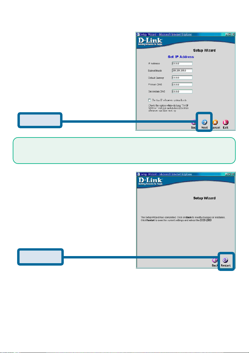
Enter the information needed by the
Intrnet Camera to connect with your
network or Internet connection. Enter
your IP Address, Subnet Mask,
Gateway and at least 1 DNS address. If you do not know what to put
in this fields, please contact your
network System Adminstrator or your
Internet Service Provider.
Click Next
Click the checkbox titled Use this IP whenever systems boots to avoid running this
install application each time you boot up the DCS-2000. Only check this if you are sure
the IP address being entered will not change the next time the DCS-2000 boots up.
If you need to make any changes,
click Back to modify your camera
settings. To accept the settings,
click Restart.
Click Restart
12
Page 13

Click OK and the DCS-2000 Internet Camera will reboot to accept the settings.
If the Installer has not made any modifications to the settings, it will warn you
that the settings were accepted but no changes were made.
You should now see the opening Installer screen with an IP address assigned
to the MAC address of the DCS-2000.
Click on Exit to close the Installer.
You have now completed the Setup Wizard and are ready to use your
camera!
Testing the DCS-2000 Internet Camera
Open your Internet browser
and type in the IP address of
the DCS-2000. In this example
the address is:
http://192.168.0.146
(your DCS-2000 may have a
different IP address based on
what you used in the Installer
program.)
The window in the center of your browser is the camera image window. You
should now see a video image and hear the audio over your computer speakers from the DCS-2000. If you are having problems please consult the
Troubleshooting section of this manual.
13
Page 14

Security
At this point it is highly recommended that you click on the Configuration button on the Home screen, and then the Tools tab to bring you to the Admin
screen and enter a password for security purposes.
To ensure the highest security and prevent unauthorized use of the Internet
Camera, the Administrator has the exclusive privilege to access the System
Administration settings to allow users the security level of entry and authorize
privileges for all users. The Internet Camera supports multi-level password
protection/access to the Internet Camera that can be restricted to defined users
who have a User Name and User Password which is assigned by the
Administrator.
The Administrator can release a public user name and password so that when
remote users access the Internet Camera they will have the right to view the
image transmitted by the Internet Camera.
When the Internet Camera is used for the first time it is highly
recommended that the Administrator set the Administrator Password
to constrain user access to the Internet Camera since the Default
settings are Null String (no password). Once the Password is defined
only the Administrator has access to the management of the Internet
Camera. This procedure should be done as soon as possible since the
security features of the Internet Camera will not be enabled until the
Administrator Password is defined.
14
Page 15

Installing the Surveillance Software
The Surveillance Software on the CD included with the DCS-2000 Internet
Camera converts the DCS-2000 into a powerful, yet flexible, surveillance
system for home or business.
Features and Benefits
• Real-time Monitoring
• Video Recording to hard disk
• High quality video
• High compression ratio
• Maximum to 16 cameras with different monitor layouts
• Smart playback
• Trigged event browsing
• Fast database searching
• Auto alarm in different ways
• Account-password protection
• Scheduled recording for each camera
• Just-in-time snapshot
• AVI export
• Motion detection for each camera
To install the Surveillance Software, click on the Setup file on the CD included with the
Internet Camera. The Welcome screen appears:
Click Next
15
Page 16

Click Yes
Please read the Software Licensing Agreement and click yes if you agree with
the agreement. Click “No” to exit.
Click Next
Enter your name and company information and click “Next”.
16
Page 17

Click Next
Select the destination directory and click “Next”.
Click Next
Select the Program Folder the software will be installed into and click “Next”.
17
Page 18

Click Next
Click “Next” and the program will begin copying onto your hard drive.
Click Finish
Click “Finish ” to end the installation.
18
Page 19

Using the DCS-2000
If you are following this manual in the order it is presented, you should now have
an operating DCS-2000 Internet Camera configured with the Installer program.
You also have installed the Surveillance Software from the CD. This section
of the manual wil deal with using the Internet Camera in two parts:
• Using the DCS-2000 with an Internet browser and accessing
the screens to control and monitor the camera.
• Using the Surveillance Software with the DCS-2000.
Using the DCS-2000 with an Internet browser
Open your Internet Explorer Webbrowser and enter the IP address for your
Internet Camera.
In the example this address is 192.168.0.146. Your address may differ.
If a window appears asking to install a Versign certificate for authentication
D-Link click “Yes”.
19
Page 20

Home Page Screen
The image from the the DCS-2000 should be visible from the Home page on
your computer monitor. There are two buttons on the left side of the Home
page:
Connection Type and Configuration.
Click Connection Type
Click on the Connection Type button to change settings related to the
connection.
20
Page 21

Home > Connections Screen
The following options are available from the Connections settings screen:
Media Option:
Option for users to disable or enable audio when viewing video.
Protocol Option
The UDP Protocol should be chosen for the most users. Generally the client
computer will automatically try these protocols in the following order, UDP ->
TCP -> HTTP.
After the client connects to the DCS-2000 successfully, the working protocol
will be displayed in “Protocol Option”. The chosen protocol will be recorded
in the user’s PC and used for the next connection. If the network environment
is changed or users want to let the web browser automatically detect the
protocol, select UDP manually and click Save to change the setting and
return Home to reconnect with the new setting.
Options:
UDP Protocol - Quality real-time performance compared to TCP. Some
packet loss due to network burst traffic and images may be obscure.
TCP Protocol - Packet loss is less likely to occur and video displays are
more accurate.
HTTP Protocol - If the network is protected by a firewall and it opens HTTP
port (80) only, HTTP protocol must be selected. In this mode, audio is
disabled and only video can be viewed.
Click the Home tab to return to the DCS-2000 Home page.
21
Page 22

Home > Configuration
Click on the Configuration button on the Home page:
Click Configuration
There are 5 tabs across the top of the Configuration screen controlling
different elements the DCS-2000 can configure. The Advanced tab is the
default screen in Configuration and Network is the default screen under
Advanced.
22
Page 23

Configuration > Advanced > Network Settings
Any changes made to these settings will require the system to
restart to validate. Make sure every field is correctly typed before
clicking on:
Reset IP address at next boot
The box is checked when first installed.To avoid performing a software installation
whenever the DCS-2000 starts, and once the network settings, especially the IP
address, are correct, uncheck this box. This option can also be disabled using the IP
Installer program. Once the option is disabled, the DCS-2000 will skip installation at
the next boot and the IP Installer program will no longer find the installed units if any
changes are necessary to the network settings. It may be necessary in that case to
to recover the DCS-2000 by restoring factory default settings. However, with this
option disabled the DCS-2000 can automatically operate normally after restarting in
case of losing power.
General
IP address - Necessary for network identification.
Subnet mask - Used to determine if the destination is in the same
subnet. The default value is “255.255.255.0”.
Default router - The gateway used to forward frames to destinations
in a different subnet. Invalid router setting will fail in
transmission to destinations in different subnet.
Primary DNS - Primary domain name server who translates names
to IP addresses.
Secondary DNS - Secondary domain name server to backup the
primary one.
SMTP
SMTP(mail) server 1 - The domain name or IP address of external email
server.
Recipient email address 1 - The email address of recipients for snapshots or log
file. Multiple recipients must be separated by
semicolon, ‘;’.
SMTP(mail) server 2 - The domain name or IP address of another email
server once the previous server is unreachable.
Recipient email address 2 - the email address of recipients for the backup server.
Return email address The return email address once the mails fail to send
out.
Continued on Next Page
23
Page 24

Configuration > Advanced >Network Settings (continued)
FTP Settings
Local FTP server port - It can be other than default port 21. After changing,
the external FTP client program must change the
server port of the connection accordingly.
1st FTP server - The domain name or IP address of the external FTP
server. The following user settings must be correctly
configured for remote access.
1st FTP user name - Granted user name on the external FTP server.
1st FTP password - Granted password on the external FTP server.
1st FTP remote folder - Granted folder on the external FTP server. The string
must conform to the external FTP server. Some FTP
servers cannot accept a preceding slash symbol
before the path if there is no virtual path mapping.
Refer to the instructions of the external FTP server
for details. The folder privilege must be open for
upload.
Primary FTP passive mode - If the DCS-2000 is located inside the network
protected by firewall, a data connection for FTP may
be prohibited. Passive mode FTP can bypass the
rule and succeed to upload snapshots. If the passive
mode is selected, the DCS-2000 can automatically
attempt for an active mode if the external FTP server
does not support passive mode.
2nd FTP server - The domain name or IP address of the external FTP
server.
2nd FTP user name - Granted user name on the backup FTP server.
2nd FTP password - Granted password on the backup FTP server.
2nd FTP remote folder - Granted folder on the backup FTP server.
Secondary FTP passive
Mode - Passive mode setting for the backup FTP server.
HTTP Settings
Http port - Can be to other than the default port 80. Once the
port is changed, users must be informed for
successful connection. For instance, when the
administrator changes the HTTP port of the DCS2000, whose IP address is 192.168.0.100 from 80 to
8080, users must type in the web browser
“http://192.168.0.100:8080” instead of
“http://192.168.0.100”.
Click Apply to make changes effective
24
Page 25

Configuration > Advanced >Network Settings (continued)
Streaming Screen
Control channel port - It can be other than default port 5001 to cooperate
with the port opened by the firewall.
Audio channel port - It can be other than default port 5002 to cooperate
with the port opened by the firewall.
Video channel port - It can be other than default port 5003 to cooperate
with the port opened by the firewall.
Improve audio quality in
low bandwidth
environment - In a low network bandwidth environment, users can
check this option to improving audio quality by
sacrificing some real-time synchronization.
Click Apply to make changes effective
Some invalid settings may cause system failure to respond. Change
the configuration only if necessary and consult with network supervisor
or experienced users for correct settings. Once the system is lost
contact, refer to Appendix A for reset and restore procedures.
Configuration > Advanced > Video Settings
Click Video
Click the video button from the Configuration screen to access video settings
that effect how the video image appears.
25
Page 26

Configuration > Advanced > Video Settings
Text on video - Text will be displayed in the black bar above the
video window with a timestamp. The timestamp is
captured from the date and time of the DCS-2000
and is maintained by a built-in real-time clock.
Color - Select the option for color or monochrome video
display.
Size - There are three options for two video sizes. “Half” is
a quarter size of “Normal”. “Half x 2” has the
same video size as “Normal” but has worse quality.
However it consumes less network bandwidth.
Power line frequency
(for fluorescent light) - The fluorescent light will flash according to the power
line frequency and depends on the local utility.
Change the frequency setting to eliminate
uncomfortable flash image when the light source is
only fluorescent light.
26
Page 27

Configuration > Advanced > Video Settings
There are three dependent parameters provided for video
performance adjustment.
Maximum frame rate- Limits the maximal refresh frame rate that can be
combined with the “Video quality control” to
optimize the bandwidth utilization and video quality. If
users want to fix the bandwidth utilization regardless
of the video quality, choose “Fix bit rate” and
select the desired bandwidth. The video quality may
be poor in order to send maximal frames within the
limited bandwidth when images change drastically.
Consequently to ensure the video detail (quantization
rate) regardless of the network, it will utilize more
bandwidth to send the maximal frames when images
change drastically.
Flip - Vertically rotate the video.
Mirror - Horizontally rotate the video. Check both if DCS-
2000 is installed upside down.
White balance - Choose the suitable option for the best color
temperature.
Tune Video for the best performance
“Best performance” means the image refresh rate should be the fastest possible and
the video quality should be the best possible at the lowest network bandwidth
possible. Three factors, “Maximum frame rate”, “Fix bit rate”, and “Fix quality”
in the Video configuration page, are related to the performance.
My priority is real-time motion images
To achieve a real-time visual effect, the network bandwidth should be large enough to
transmit 20 image frames per second (fps) or more. If you are on a broadband network
over 1 Mbps, you can fix the bit rate to 1000Kbps or 1200Kbps, or fix the quality to
achieve the maximum frames. The maximum frame rate is 25 in 50Hz system and 30
in 60Hz system. If your network bandwidth is more than 384Kbps, you can fix the bit
rate according to your bandwidth and set the maximum frame rate to 25 or 30. If the
images vary dramatically in your environment, you may slow down the maximum
frame rate to 20 to decrease the transmitted data for better video quality, since the
human eye could not easily tell the difference between 20 and 25 or 30 frames per
second. If your network bandwidth is below 384 Kbps, you should fix the bit rate
according to your bandwidth and try out the best performance by tuning the maximum
frame rate. The larger frame rate in slow network will blur the images. You may also
try to choose “Half” in size option for better images or “Halfx2” for larger image size.
Because the network has burst constraints and everyone’s environment is not the
same, any poor connection will drop the normal performance.
27
Page 28

Tune Video for the best performance (continued)
My priority is clear identification for each image
To have the best video quality, you should fix the quality to detailed or excellent and
tune the maximum frame rate to suit for your network bandwidth. If you get some
broken pictures in a slow network, you can choose TCP protocol in “Connection
type” for more accurate transmission but the received images may have certain time
delay. Note that any slow connection in with multiple users will drop the performance.
I want to compromise between real-time and clear images
If you have a broadband network, choose fix quality to normal or better rather than fix
the bandwidth. Otherwise fix the bandwidth according to your actual network speed
and set the frame rate to 30. If the images look bad, select the lower frame rate above
15. If the images are not improved, select the lower bandwidth.
Configuration > Advanced > Image Settings
Click Image Settings
Click the video button from the Configuration screen to access video settings
that effect how the video image appears.
From this screen you can fine tune the video image.
Brightness” “Contrast” “Saturation” and “Hue”are all adjusted in the same
manner. For each video compensation you can set from among eleven levels ranged
from -5 to +5.
You may press to fine-tune the image and see what effect the setting will
have on the image. When the image is acceptable, press to memorize the
image settings or to recall the original settings. If parameters are changed
without saving, they will be used until the next system startup.
28
Page 29

Configuration > Advanced > Motion Detection
Click Motion Detection
Click the Motion Detection button from the Configuration screen to access
settings that effect how the DCS-2000 Internet Camera can serve as a
security device by recording only when motion is detected.
Enable motion detection - Check this option to turn on the motion detection.
New - Click on this button to add a new window. At most,
three windows can exist at the same time. Use the
mouse to drag the window frame to resize or the title
bar to move. Clicking on the ‘x’ at the upper right
corner of the window can delete the window.
Remember to save to validate the changes.
Save - Click on this button to save the related settings
regarding to the window. A graphic bar will rise or fall
depending on the image variation. A green bar means
the image variation is under monitoring level and a
red bar means the image variation is over monitoring
level. When the bar goes red, the detected window
will also be outlined in red. While back to the
homepage, the monitored window will hide but the
red frame will show when motion is detected.
29
Page 30

Configuration > Advanced >Motion Detection (continued)
Window Name - The text entered here will show at the top of the
window.
Sensitivity - Sets the measurable difference between two
sequential images that would indicate motion.
Percentage - Decides the space ratio of motioned objects over the
monitored window. Higher sensitivity and small
percentage will make any motion more easily
detected.
30
Page 31

Configuration > Tools > Admin
Click on the Tools tab to access 4 utility screens for controlling and adminstering the
DCS-2000. The default screen in Tools is the Admin screen.
The DCS-2000 is shipped without any passwords by default. This means anyone can
access the DCS-2000 (including the Configuration) as long as the IP address is
known. It is necessary to assign a password if the DCS-2000 is intended to be
accessed by others.
Type a password in the New Password field to enable protection, and then confirm
the password in Confirm Password field.
This password is used to identify the administrator. Then add an account with User
name and User Password for your friends in the Add user section.
You can provide twenty accounts for your valuable customers or friends. Each
account identifies the access right rather than the real visitor. That allows multiple
visitors share the same account of different level. An option to Permit to access DI/
DO (Digital In/Digital Out) is provided for each account. Some users may need to be
prohibited from controlling your attached security devices.
Guest account: This option allows anyone uses “demo” as the user name to
view without password while they can watch only. This is
useful for exhibition and separating the guests from normal
users.
31
Page 32
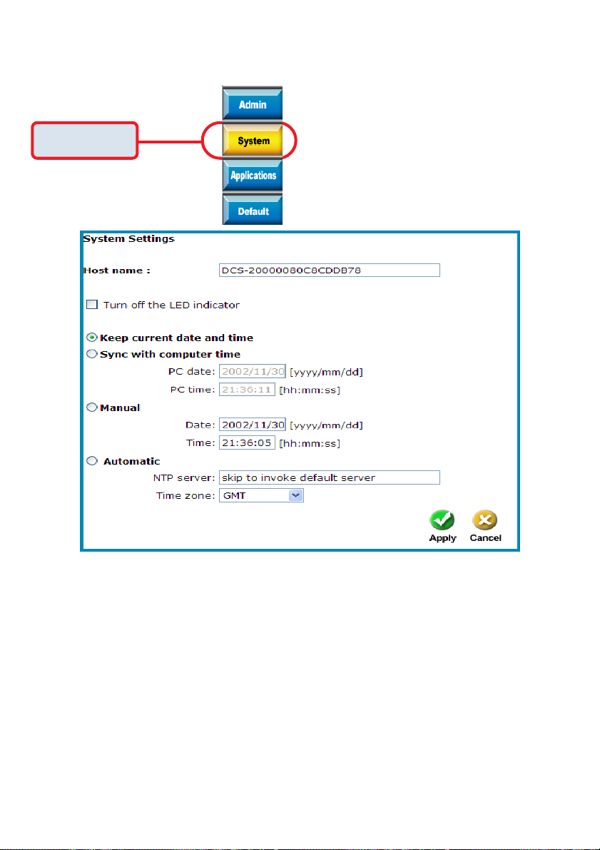
Configuration > Tools > System
Click on the System button to access the System settings from the Tools menu.
Click System
Host name - The text will display as the title at the top of the
main page.
Turn off the LED indicator - Check this option to shut off the LED next to
the lens. It can prevent someone from
observing the operation of the Internet Camera.
Keep current date and
time - Click to save the current date and time of DCS-
2000. An internal real-time clock maintains the
date and time even when the power of the
system is turned off.
Sync with computer time- Synchronize the date and time of DCS-2000
with the local computer. The date and time of
the PC is displayed and updated in the DCS-
2000.
32
Page 33

Configuration > Tools > System
Manual - Adjust the date and time according to what is
entered by the administrator. Notice the format
in the related field while typing.
Automatic - Synchronize with the NTP server over the
Internet whenever the DCS-2000 starts up. It
will fail if the assigned timeserver cannot be
reached.
NTP server - Assign the IP address or domain name of the
timeserver. Leaving the text box blank will let
DCS-2000 connect to default timeservers.
Time zone - Used to adjust the hour of timeservers for local
settings.
Click on Apply to validate changes.
Configuration > Tools > Applications
Click on the Applications button to access the Applications settings from the Tools
menu.
Click Applications
33
Page 34

Configuration > Tools > Applications (Continued)
34
Page 35

Configuration > Tools > Applications (Continued)
Weekly schedule:
Sunday through Saturday - Select the weekdays that should perform the
following operations:
Snapshots begin at - Set the time to start operations. Setting the begin
time the as same as stop time will force operations
to operate continuously
Snapshots stop at - Set the time to stop operations.
Event operation
Delay second(s) before
detecting next event - Set the time delay before restarting to check the
trigger condition when the current condition is
triggered.
Take snapshots at second(s)
after event - After a snapshot is taken because of a trigger,
another snapshot will be taken after the configured
seconds.
Trigger condition - There are 4 conditions related to the digital input and
three windows for motion detection. There can be
multiple selections. Select the appropriate digital
input condition according to the characteristics of
the external device. “High”, “low” indicate external
voltage input for level trigger, while “rising”, “falling” is
for edge trigger. There are three windows shown for
the name you defined for motion detection.
“Undefined” will show instead of the window title if
motion detection is not setup yet. In such a case,
clicking on the “Motion detection” in the note will
direct you to the Configuration page for Motion
detection.
Trigger action - There are four options for two actions regarding to
either condition. They can have multiple selections.
While choosing the trigger output alarm, the digital
output will short both pins to connect the circuit of
the attached external device; otherwise both pins will
be open. While choosing to upload snapshots, the
method can be either email or FTP. The snapshot
names will be “videopre.jpg”, videotrg.jpg”, and
“videopos.jpg” respectively for the snapshots before
event, right upon event, and after event. The date and
time suffix may be added according to the option.
Confirm the external mail or FTP server settings in
network configuration.
Reset output - check and save this option to reset the external
device at the digital output back to the original state.
35
Page 36

Configuration > Tools > Applications (Continued)
Sequential operation
Snapshot every second(s) - The DCS-2000 will send snapshots at the specified
interval to the external server according to the
chosen method. Remember this operation is still
subject to the weekly schedule.
Send snapshots by email - Any upload action specified in the options above will
use the method chosen here. The captured snapshot
named “video.jpg” will be attached in the email with
subject “Periodic snapshots”.
Send snapshots by FTP - The captured snapshots will upload to the external
FTP server with the file name depending on the next
option. It can be used to refresh the captured image
stored in the external web server to build creative
homepages.
FTP put snapshots with date
and time suffix - If the suffix is added, the captured date and time can
be easily differentiated from the snapshot file name
in either sequential or event operation. For instance,
“video@20020102030405.jpg” means the JPEG
image was captured at 4 minutes and 5 seconds
after 3 o’clock, January 1st, A.D. 2002. If the suffix is
omitted, the file named “video.jpg” on the external
FTP server will be refreshed at the specified interval.
Click on Apply to validate changes
36
Page 37
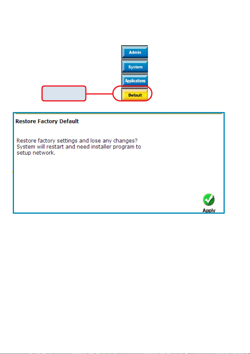
Configuration > Tools > Default
Click on the Default button to access the factory Default settings from the Tools
menu.
Click Default
Click Apply on the screen to restore the factory default settings. This means
any changes made will be lost and the system will be reset to the initial
status when shipped from the factory. After confirmation, the system will
restart and require the Installer software program to setup the DCS-2000.
37
Page 38

Configuration > Status > Device Info
Click on the Status tab to access Device Info and a Log of DCS-2000 system
activity. The Device Info is the default screen when you click on the Status tab.
The Device Info screen lists the following important settings that are currently set for
the DCS-200:
Firmware Version number
Mac Address
IP Address
Subnet Mask
Default router address
Primary DNS address
Secondary DNS Address
Configuration > Status > Log
Click on the Log button to access a system log of system activity from the Status
menu. The content of the log file reveals useful inforamtion about the current
configuration and connection logged after the DCS-2000 boots up.
Click Log
38
Page 39

Configuration > Help
Click on the Help tab to access descriptions of the particular function you need help
with. The help screen is organized in the order of the tabs and then each menu item
under that tab.
39
Page 40

Firmware Upgrades
The DCS-2000 Internet Camera supports upgrades to the firmware (the software that
controls the operation in the DCS-2000). D-Link will supply the latest firmware version
on the D-Link support Web site at: support.dlink.com.
To upgrade the firmware:
Download the latest firmware file from D-Link.
Click on the file Upgrade Wizard located on the CD enclosed with the DCS-2000.
Power on the DCS-2000 and connect it to the Ethernet port.
The Wizard will ask for the IP Address of your camera and for your adminstrator
password:
Click Next
The Upgrade Wizard will attempt to find the DCS-2000. If it cannot, an error message
indicating this will appear.
If the Upgrade Wizard finds the Internet Camera the following screen asks for the file
name or gives you the choice to browse for the file. The file name should be
FLASH.BIN for the DCS-2000 Internet Camera.
Click Next
40
Page 41

Firmware Upgrades (continued)
The firmware file is scanned by the Upgrade Wizard and the version is reported
to you.
Click Yes
After clicking “Yes” the upgrade begins. The progress of the upgrade is displayed
on the this screen:
Click Exit
The upgrade has been completed.
The download firmware procedure cannot be interrupted.
If the power or network connections are broken during
the download procedure it might possibly cause serious
damage to the Internet Camera.
Warning
41
Page 42

Using the Surveillance Software
Installation of the Surveillance Software is detailed in an earlier section
of this manual titled Installation of the Surveillance Software under
the main section titled Software Installation.
Upon completion of the installation of the Surveillance Software, you can run
the Monitor program from:
Start\ Program Files\D-Link\Surveillance System Software\Monitor
or the directory you specified during the installation.
You will be asked to set the root password first, and the password should be at
least 6 characters in length.
Monitor Program
Click OK
A successful message box will show if you set the root password successfully.
Click OK
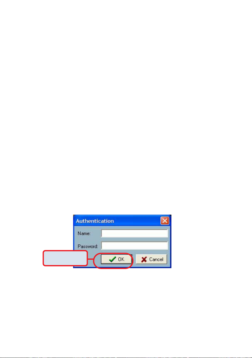
An Authentication dialog will appear. Enter “root” login for the first time and
enter a password..
root
**********
Click OK
You will see the Monitor program on your display.
42
Page 43

Using the Surveillance Software (continued)
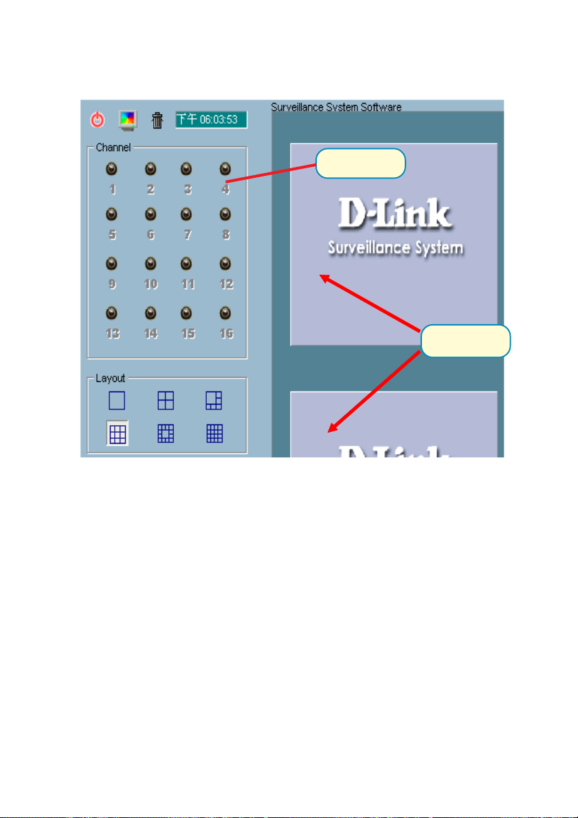
Monitor Program Main Screen:
Misc. Functions
Layout Area
Recording Settings
Hard Disk Status
Channel Area
Video Area
DI/DO, Telnet & Alert Messages
Descriptions of the sections of the Monitor program Main screen:
• Miscellanous functions:
Including application exit, snapshot, full screen monitoring, and
Function menu for calling global settings, configuration, and
backup. Tips are provided when you move the mouse cursor on
them.
• Channel area
This area displays the status of each video channel including:
connection, recording, selected, and alert information.
• Video area
In this area, you can see the video of accessible channel, and
some convenient controls.
43
Page 44
Using the Surveillance Software (continued)
• Layout area
You can change the monitoring layout in this area.
• Recording settings
You can record video onto your hard disk. The recording
schedule is controlled with the Scheduling tools.
• Hard disk status
In this area, you can get the hard disk status. This reminds
you to arrange the recorded video database.
• DI/DO control
Receive the digital input signal and send digital output signal.
• Telnet control
Telnet to remote camera to do low level control
• Alert Message
Display the last alert messages.
Logging In
You need to login to use the Surveillance Software system. There are two
privileges in the account-password system: the root (administrator) and the
general user
.
Click OK
If you have the root privilege, you have the right to do the following items:
• Run the configuration tool
• Change the recording schedule
• Change the local settings
General users can only monitor the surveillance videos and change the layout
of the Monitor program, but you do not have the right to change any configuration
including recording schedule and local settings.
44
Page 45

When you first login, you should configure the DCS-2000 from the Camera
Configurations menu. Once you set up the root (administrator) privilege, you
can run the Configuration.
The message: “ Before configuration, all recordings will be stopped”
will appear to warn you that any recording that is occuring will stop when you
access Camera Configurations
Home > Camera Configuration Screen
Function setting buttons
Camera selections
Local Settings
Setup Page
45
Page 46

Home > Camera Configuration Screen (continued)
In the local settings there are four main functions:
Insert – Used to insert a camera in the camera list. After you specify the IP
address and port, click the “Insert” button. The program will try to connect to
the DCS-2000. If the connection succeeds, the root password of the remote
DCS-2000 camera is required. If you provide the correct password, the camera
will be inserted in the list
Delete – This operation deletes the camera from the camera list.
Password – Changes the local “root” password.
Stop – Provides a way to stop the network connection when the connection
elapses for a long time.
46
Page 47

Changing the Camera Order in the List
You can drag and drop the gray area (fixed area) of the camera list grid to
change the arrangement of cameras. This makes it easy to rearrange the
cameras.
Press left mouse
button in gray area.
Move mouse to where you want to move and release
Move mouse where you want to move and release the mouse button.
mouse button. Here video 1 will be moved to the 10th row
Here Video 1 will be moved to the 10th row.
Motion Window and Alert Settings
Show Window Options – If Motion Detection is enabled for the selected
DCS-2000 camera, each motion window can be turned on in “Show
Window Options”. Once the motion window is turned on, it will be shown
as a green rectangle in monitoring screen. If you just want to see the
motion window when alerted, you can also turn on the alert window
separately. The alert window will be shown in red rectangle when an alert
occurs.
Alert Settings – Some special actions can be performed, such as generating
an alert sound or starting recording when motion is detected or a digital
input is triggered. The digital input can be high-triggered or low-triggered.
It depends on your setting. You can also specify the period to record after
the alert-trigger.
47
Page 48

Saving the Changes
Once you click the “Save” button, the changes in the configuration will be saved
and will validate immediately.
Global Settings
Click on the Global Settings item from the Function Menu.
Snapshot directory – the directory for storing the snapshot data.
Recording directory – the directory for storing the recorded video data.
48
Page 49

Reserved space – Indicates how many bytes should be reserved on the hard
disk. If the recording data exceed disk capacity, the new video data will replace
the oldest data.
Modulation Mode – For selecting the input signal format (NTSC or PAL).
Alert Sound – Select sound to play when for an alert.
Display options – In each video frame, there are two status bars, which contain
“Camera location”, “Connect time”, “Remote time” and “Record time”. All of
them can be enabled here individually.
Location (Channel number + Text on Video
Connect Time (day hour:min)
Remote Time
Recording Time (day hour:min)
Backup Settings – Select the backup directory, the backup size for your backup
media, and the backup locations. Also you can delete backup locations here.
The maximum locations can not exceed 32.
Last Backup Time – Indicates the last time a backup occurred. “All Backup”
means all the data in this location have been backup, and “No Data” means
there is no data stored in this location.
Internet Settings – Set the proxy and IP filters.
49
Page 50

Check here to enable proxy.
Set the proxy
Check here to enable filter.
Add an IP address
Delete an IP address
Enter IP address to add
Click OK
If you enable proxy server and enable IP restriction, the listed IP
addresses will not use the proxy.
Connecting to the DCS-2000
Once you connect to the DCS-2000, you can drag and drop a camera to the
video area.
In the channel area, if you do not set up the camera, the color of the camera
number will be gray. Once you set up the camera, the color of the camera
number will turn into blue. You can drag and drop the camera to the video
area, and apply other features if you have the the privileges.
There is a unique light signal above each camera’s number. It indicates the
status of the camera:
Off – Camera is not connected.
Green – The green light means the camera is connected.
Red – The red light indicates the camera is both connected and in
recording mode.
Blink – If motion detection is enabled and there an alert occurred, the
light will blink.
50
Page 51

Selected Channel
Recording
Configured Channel
Trash Can
Connected & Monitoring
Not Connected (No Video)
Configured Channel
Not Configured Channel
If you don’t want to monitor a video channel, you can drag and drop the video (in
the video area) to the trashcan. Here we’ll shown the drag and drop step by
step:
1. - Select the video of the channel to be discarded
2. - Move the mouse cursor to the channel number.
3. - Press and hold the left mouse button, the cursor will change according to
the area where it is droppable or not.
4. - Move the mouse cursor to a droppable area (in this case, it should be the
video area), and release the mouse button. In each layout, one video channel
is corresponding to one and only one video box in the video area. Therefore, the
drag and drop from channel number to video box also can be treated as “exchange
of videos in video box”, that is, if the video of channel 1 is displayed at video box
A, and the video of channel 2 is displayed at video box B, when you drag channel
2 to video box A, channel 2 is displayed at video box A and channel 1 is displayed
at video box B.
51
Page 52
Channel number
Droppable Areas
The drag and drop can also apply to the change of videos. In the video area, if
you want to exchange the videos of different channel, you can drag the video
and drop to where you want to locate the video. If the destination video box is
empty, then video in the source video box will be shown on destination video
box, and the source video box will be empty. If the destination video box
contains video of some channel, then the videos in the source and destination
video box will be exchanged.
52
Page 53

The Layout
There are six layouts in the monitor tool. You can select (by clicking the left
mouse button on the icon) which videos you want to monitor. In each layout,
you can drag and drop the “channel number” to any video box in the video area.
If all conditions are okay, then the video will appear in the video box, and the old
video is replaced.
1 Camera Layout
9 Cameras Layout
6 Camera Layout
16 Camera Layout
The video positions in each layout are saved for the next time the layout is
selected for monitoring.
When you want to view one individual camera, you can double-click on the
video in the video area. The layout is now changed to the view of single video
whose size is twice the original one. You can click the “up” or “down” button to
view different cameras, and clicking the “Back” button will switch to the previous
selected layout.
Back to Previous Layout
Double-click to switch to 2X Size Video
Switch Between Cameras
53
Page 54

Record & Schedule
Record – Record the selected channel manually.
Stop – Stop recording the selected channel manually.
Scheduling – Arrange recording schedule
Enable Scheduler – Record according to the scheduler
settings.
DI/DO Control
Only one user with root privilege can access the DI/DO control at the same
time. Refer to the following figure to control.
Digital Input is High
Set Digital Output to Low
Set Digital Output to High
Telnet Control
You can do some low level controls such as manual DI/DO control.
Channel Number
Input Command
Connect
54
Telnet messages
Disconnect
Page 55

Alert Message
If you turn on the Alert function, and a motion detected is triggered when set in
the configuration, the alert message will show in this window. The message
format is described as follows:
“time”=>”alert type” #”channel number”(“win1”,”win2",”win3")
For example, the message “03:47:25 PM=>MO #5(0,1,1)” means that motion
detection alert occurred at 03:47:25 PM on motion window 2 and motion window
3.
Backup
The “Backup” function will help you to archive the recorded data according to
the location and size you selected in “Global Settings”. You can duplicate the
backup data to a removable device such as CD-ROM, ZIP disk, DVD-RAM or
tape manually. After the backup starts, you cannot configure the camera or
change any settings. You can cancel the backup process by selecting “Cancel
Backup” option. After the backup completes, a message appears informing
you the backup is complete.
55
Page 56

Miscellaneous Functions
Power – Close the application and save last settings
Full Screen – Switch to full screen, double click screen to return back
Local Time – Display the current time
Snapshot – Snapshot each view in current layout mode, and save them as
bitmap file to hard disk. You can set the directory in “global settings”.
Stop Alert Sound – Whenever alert occurrs, the alert sound will start to play.
You can press this button to stop the alert sound and see the alert messages.
Scheduling
The Scheduling helps you to schedule the recoding time of the output from
the DCS-2000. You can easily specify the time of recording via both our
graphic user interface and time period selection. Features include:
• Easy to use graphical user interface
• One-on-one camera scheduling
• Up to 9 schedule schemes for each camera
• Automatic period recording
56
Page 57

1
2
3
4
6
7
5
The layout of the scheduler tool is divided into 9 sections:
Section 1 of the scheduler tool is the Hour time-line. It helps you create the
minute-based schedule. You can refer to the Schedule With Time Lines section
on page 59 for more details. Sections 2, 3 and 4 are Day time-line, Week
time-line and Month time-line respectively.
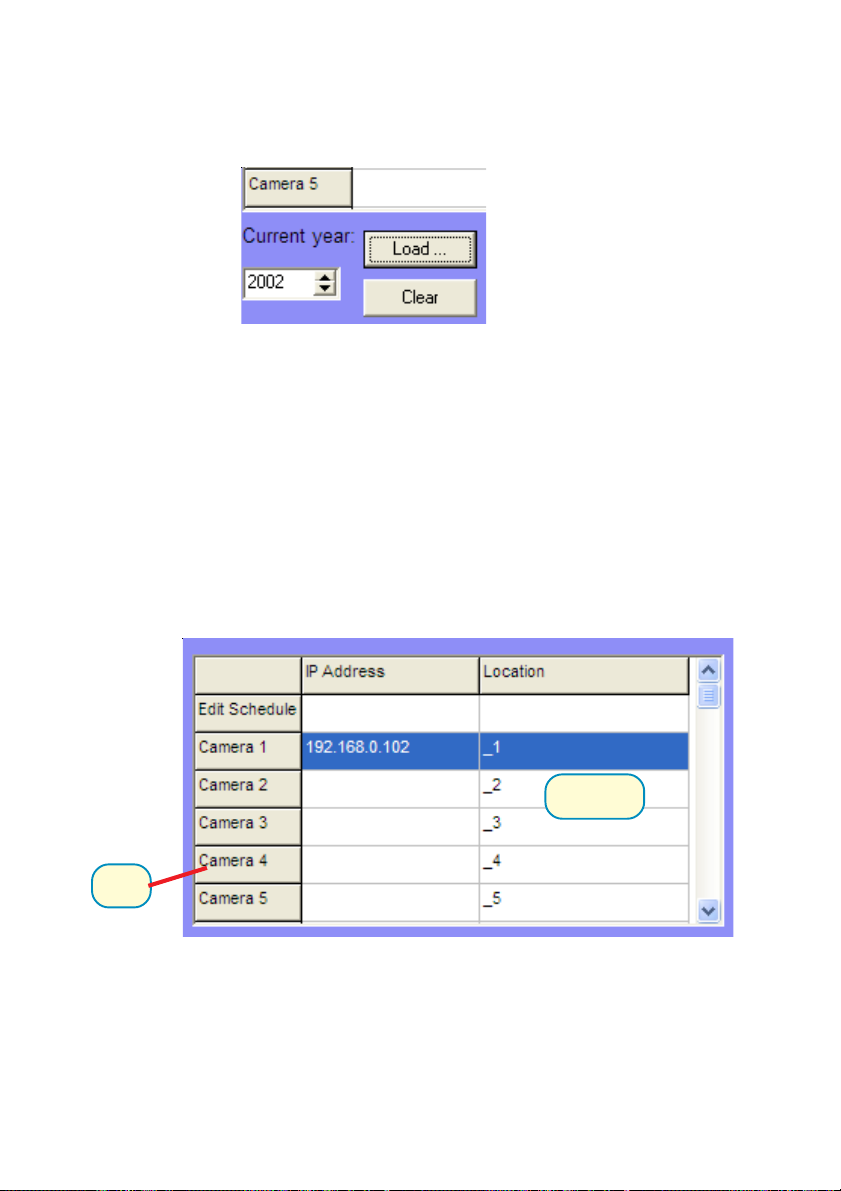
Section 5 is the Current year settings, which consists two components: Year
selector and Set year button. Their function is to change the year that is
being scheduled.
Section 6 is the camera selection area, it provides the IP addresses and location
information for your reference. Their is an editing schedule space for saving a
temporary schedule.
Sections 7 and 8 consists of “Begin time selector”, “End time selector”,
“Period selector”, “Addition button”, and “Erase button”. These components
help you choose a period of time in which to add or delete records in the schedule.
Section 9 is the operation buttons for the schedule-record-files and close window
button.
9
8
57
Page 58
Current Year Settings And Camera Selector
By default, the scheduler is running with the current date selected on the timelines and Date-time picker. Therefore, the current scheduling year is the year
that you run the scheduler tool. To change the year setting:
1. Use the up (increase) and down (decrease) arrows to adjust the year setting.
2. The Date-time selector in Section 7 (see above) will change the year
concurrently.
If you change the year with the Date-time selector, the current year setting will
also be changed.
The following is the camera selector:
Edit Space
Camera
The Camera selector contains two kind of items. The first one is designed
for helping edit the schedule and is at row 1 of the selector as shown above.
If you want to make a schedule that does not belong to any camera, you can
select this row for editing.
The second item is the camera selector. When you click on the camera row,
the scheduling tool will associate the current editing space to the current
selected camera.
58
Page 59

If users have configured the Surveillance Software and the DCS-2000
camera, the IP address and location will show the correct setting. Please
note that when users switch between cameras, the changing of the schedule
will be saved automatically.
The Schedule-Record-File operations
There are five related buttons:
Load: This operation allows the users load other schedules
from the schedule database for this camera.
Clear: This operation will clear all the schedule markers in the
current editing area. Note that users must choose
“save” or “refresh” themselves.
Save: The button is for applying the changes for the current
schedule.
Save As: To save the current schedule-record-file to another file
name, this button will perform this.
Refresh: The scheduling tool will load the old data from the
schedule-record-file. The current changes will be lost.
Schedule with Time Lines
There are four time-lines: Hour unit time-line, Day unit time-line, Week unit
time-line and Month unit time-line. You can create your schedule in all time-
lines. These four time lines are related to the same database, that is, if you
have rescheduled one time-line, the changes will be applied to the other three
corresponding time-lines.
59
Page 60

Scheduling Concept
Time Unit
Each time-line has its own basic marking unit, if you make your schedule
on different time-line from what was intended, the resulting schedule is
will be very different from what was intended.
Scheduling example:
Click on 10:00 from the Hour-time line.
The next time unit is 10:05
If you click the left mouse button on the Hour time-line as the time
information, 10:00, then the recording time is:
5 Minutes recording record
5 Minutes recording record within 20 Minutes
5 Minutes recording record within 1 Hour
5 Minutes recording record within half-day
60
Page 61

The marking concept is that there exists different time units of
each time-line. If there is any smallest time unit, which is marked
for recording, then the time unit for each time-line that contains
the time will be marked.
Example:
In an Hour time-line, 1:10~1:15(include lower bound, exclude upper
bound) is marked, although only in 1:10~1:15 the recording is valid.
As situation of point 1, in Day time-line, 1:00~1:20(include lower bound,
exclude upper bound) is marked, although only in 1:10~1:15 the recording
is valid.
As situation of point 1, in Week time-line, 1:00~2:00 (include lower bound,
exclude upper bound) is marked, although only in 1:10~1:15 the recording
is valid.
As situation of point 1, in Month time-line, 00:00~12:00 (include lower
bound, exclude upper bound) is marked, although only in 1:10~1:15 the
recording is valid.
Using Mouse buttons in the Scheduler
The scheduler tool is designed for a two-button mouse. In this manual, we use
left mouse button and right mouse button to distinguish them.
When you click or double click the left mouse button over the time-line, the
time-line will mark the time for the scheme of the schedule; if you click or double
click the right mouse button over the time-line, the time-line will unmark (clear)
the record in the schedule.
Operations over time-lines which are left mouse button based are designed for
marking the time (make a recording, red bars on time-line) in the schedule.
The operations which are right mouse button based are designed for cancelling
the recording (unmark the time, green bars on time-line) in the schedule.
61
Page 62
When you move your mouse over the time-lines, the scheduler will show the
Marked
date/time information under the cursor to remind you of the time at the mouse
cursor position.
Marked
Make Serial Selections
If you want to mark/unmark a series of time units, the following steps demonstrate
the method.
1. - Press and hold the left mouse button:
2: - Note the time information from the tips and move the mouse to the
target time
62
Page 63

3.- Release the left mouse button
If you press the right mouse button in the above steps, the scheduler tool draw
a green bar in the time-line, and finally clear the records in the unmarked region.
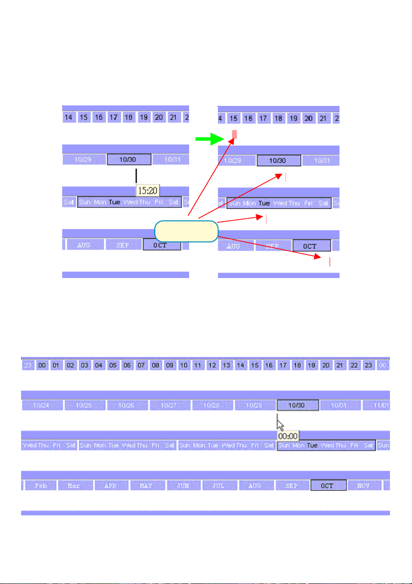
Week Time-Line
Left scroll area
Selected day
Cursor
Selected week
Right scroll area
Date/time information
63
Page 64

Marking/Unmarking the Recording Time
The one-click unit of the Week time-line is one hour. It means a continuous
one-hour recording schedule is marked/unmarked if you click the mouse button.
You can also press and hold the mouse button to mark/unmark continuous
units.
Result in hour time-line
Click
Result in month time-line
Result in day time-line
If you move the mouse cursor to the most left part of the time line, the time-line
will scroll one day-unit at a time, and the earlier date will be shown in the week
time-line, and vice versa.
When a left mouse button click occurs at an upper time-line area (the week
day indicator), the current date selection is changed, and the change also
effects all other time-lines.
Selected day
Cursor
Scroll to right area
Scroll to left area
Time information of current cursor
Marking/Unmarking the Recording Time
The one-click time unit in a Day time-line is 20 minutes. The operating method
is the same as Week time-line and Month time-line. Please refer to the
Logging-in section in the Using the Surveillance Software section of this
manual for details about User Privileges and logging-in.
64
Page 65

Scrolling and Switch Date in Day Time-Line
Time of the cursor position
Cursor
Moving the mouse cursor to the left-most part of the Day time-line will cause
the time-line to scroll one day earlier. If you keep the mouse cursor within the
same area, the time-line will continue scroll and vice versa.
Click at the Day information area of Day time-line will cause the selected day
to be changed and the change will also effect all other time-lines.
Hour Time-Line
Left scroll area
Selected day
Non-selected day
Right scroll area
The one-click unit in the Hour time-line is five minutes, and it’s also the smallest
unit of time in the scheduling tool. The operating method is the same as the
other three time-lines.
Scrolling and Switching Time in the Hour Time-Line
The scrolling unit of Hour time-line is one hour. Moving the mouse cursor to
the left-most part of the time-line will scroll the time-line to earlier time and vice
versa. The selection unit of this time-line is one day, when you click on the
Hour information area in the time-line, the selected day will be changed and
the other three time-lines will be changed as well.
When you move your mouse over the hour-line, the scheduler tool will show
the time of the current cursor position. This will help to make a detailed schedule.
65
Page 66

Schedule with Time Picker
Add
Erase
There are three controlling units in both the start and end time selectors. The
first controlling unit is the Date Picker. You can select the year, month and day
with it. Once you select the date in a different year, the data file will switch
automatically.
Remember to make the begin time earlier than the end time. Otherwise the
add action will be ignored.
After you have selected a time period with the begin time and the end time
picker, you can click the “Add” button or “Erase” button to add or clear the
scheduling information within the time period. Remember that only if you click
on the “Apply” button, the scheduling changes will be written back to the data
file. This means the scheduling is valid only if you “Apply” the changes
Select period
Once
Every Hour
Every Day
Every Week
If you select the “Once” option, the scheduler tool will mark the time according
to the begin time and end time. It includes year, month, day, hour, and minute
selections. The following picture illustrates this situation:
66
Page 67

Once:
67
Page 68

Every hour:
If this option is selected, only the selection of minutes is valid. And within
the whole year, every minute that meet the setting will be marked. The
situation is shown below:
68
Page 69

Every day:
If you select this option, only the selections of hour and minute is valid. The time
that meets the selection will be marked within the year. The result shown below
is an example:
69
Page 70

Every week
The functionality is similar to other options. The scheduler tool will check the
dates for their day of week, and apply the time mark to every week within the
year. Only the day of week, hour and minute are valid.
70
Page 71

Every month
In this option, only the date (exclude the month and year), hour and minute are
valid. Therefore, the result is as follows:
71
Page 72

Playback Program
The Playback program is a powerful tool to assist you in browsing the recorded
video database. It has two display modes (Normal display mode, Preview Mode)
and three playback methods (Full Range, Time Period, Events Preview). The
main tools it provides include:
Powerful play control tool:
• Play
• Stop
• Pause
• Step forward
• Fast play (from x1 to x16)
• Slow play (from /1 to /16)
Convenient display adjustment tool:
• Zoom in (from 1:1 to 2.25:1)
• Zoom out (from 1:1 to 1:2)
• Full screen
Flexible searching range adjustment tool:
• User input (from full range to 1 second)
• Zoom in (from full range to 10 seconds)
• Zoom out (up to full range)
• Page searching
• Full range
Various exporting tools:
• AVI file transducer
• BMP file snapshot
• Output to printer directly
72
Page 73

Playback Program
Installation of the Surveillance Software is detailed in an earlier section
of this manual titled Installation of the Surveillance Software under
the main section titled Software Installation.
Logging -in
Before you start the Playback software program, it is necessary to Log-in. For
security reasons, only the root account can log-in to Playback. To change the
password of the root account pleaserefer to the section of this manual titled
Logging-In in the main section Using the Surveillance Software.
Upon completion of the installation of the Surveillance Software, you can run
the Monitor program from:
Start\ Program Files\D-Link\Surveillance System Software\Playback
or the directory you specified during the installation.
Area Selection Indicator
Display Area.
Control Area.
Pull Bar Area.
Status Area
Histogram Area
Status Area
The main window will be shown on the top of the screen and the display resolution will
change to 1024x768 automatically. There are four main areas in the the window: Display
area, Histogram area, Control area, and Status area. There are also three controls
the Area selection indictor, the Frame selection indictor, and the Pull bar.
Explanatrions of the main Playback screen follow:
73
Page 74

Display Area
The display area shows the surveillance database of each camera by events
triggered by an alert or by time. You can change the video size through the
Display Adjustment Tool, and the playback method through the Play
Control Tool. Under the normal display mode you can double click on the
frame area to change the frame size to a 1:1 or 2.25:1 ratio.In the Preview
mode, double clicking on any frame area can change the display mode to
normal and show a 10-second interval including the event you selected.
Histogram Area
The histogram is an interactive control. Not only you can get the event’s location
in terms of time, but you can select a group of events or period from the event
histogram area and show it on the display area.
Control Area
The control area contains almost all the control selectors and toolboxes you
need to browse the database (except the page control). The Page Control
Tool is located on the right-bottom corner of the display area when the program
is operating in the preview mode. These control tools include location selector,
period selector, playback method selector, jog dial, display adjustment tool,
exporting tool, and system control tool.
Status Area
The Status Area is located at the bottom of the main window. It tells you about
the program status including display mode, display size, display speed, exporting
file format, and exporting file name.
Area Selection Indicator
In the main Playback screen on shown above the display area has been
highlighted with a yellow rectangle. This rectangle is the area selection indicator.
This indicator can be set to either Display Area or Histogram Area, by moving
your mouse cursor to the Area you want to select. When you select the Display
Area, the Display Adjustment Tool will appear in the control area, and if you
select the Histogram Area, the Display Adjustment Tool will disappear and
the Searching Range Adjustment Tool will be shown in the control area.
74
Page 75

Frame Selection Indicator
The frame selection indicator only appears when you change the display mode
to Preview Mode. It appears as a red rectangle surrounding one of the nine
Event Preview Frames. Once you select one of these frames, you can control
its play status through the jog dial in the control area.
Pull Bar
The Pull Bar is a fast, flexible control for seeking data in the selected time
period. It represents the total length of time in that period. You can click or pull
the indicator on the pull bar to the point you want to see. And the current displaying
video will halt and start to play the video sequence from the point you choose.
If the video sequence has been paused, the display area will show the point
you select without playing. The Pull Bar will only function under the normal
display mode.
Settings
After the main window is shown on the screen, you must modify the settings
to make it work properly. Click on the “Settings” button in the system control
tool, and the dialog box appears on the screen as shown below:
Explanations of the Settings screen follow:
75
Page 76

Database path
The most important item in the settings dialog is the database path setting.
You must set it to the directory that contains the surveillance database to
make the program work properly.
AVI file location
It sets the storing directory when you export AVI files. The exported AVI
files will be stored in the sub-directory under the directory you set here
with the name of the location you select.
Bitmap file location
It sets the directory to use the for snapshots when exported as bitmap
files. These exported bitmap files will be stored in the sub-directory under
the directory you set here with the name of the location you select.
Bitmap color depth
This setting changes the color depth of the exporting bitmap file. It is
suggested to use more than 16 bits color depth for the best picture quality.
AVI compression mode
Unlike the exporting of bitmap files, only 16 bits of color depth are used to
export the AVI file. During the AVI compression mode selection, you can
select one of the compression methods that your computer supports to
export the AVI file.
Alert window settings
There are three alert windows you can activate during using the monitor
program. In the playback program, you can choose whether these alert
windows will be shown or not. If you check one window, then you will see
that rectangle in green or red color shown in the displaying video sequence.
Modulation mode
The modulation modeshould not be changed with knowledge of the various
modes . The quality of the video depends on how you recorded the video
sequence in the monitor program. If you select the wrong mode, the video
shown in the display area will become deformed. If you choose the wrong
modulation mode, you may open the settings dialog again, change to the
correct mode, and restart the playback program, It should then display
properly.
76
Page 77

Control panel position
The Control panel provides you a very convenient method to change the position
of the control area to fit your needs.
Once you change the setting of modulation or control panel position, you have
to restart the program to for these changes to take effect. If you set the database
path correctly, the video sequence will start displaying in the normal display
mode when you click on the “Ok” button.
Normal (Single Frame) Mode
You can enter the Normal Mode when you:
• Change the database path in the settings dialog
• Change the location selector to another location
• Change the playback method selector to “Full Range”
• Change the playback method selector to “Time Period”
• Double click on one of the nine frames in the display area under
the preview mode.
Under the single frame mode, you can use all the tools the playback program
provided except the Page Control. In this mode, the two labels under the pull
bar show the start and end time of the period individually as shown below:
Period Start Time Label
Period End Time Label
Histogram Area
The Histogram Area in the single frame mode only shows the event’s occurred
time and the percentage of motion detection with red bars. If you want to access
the Histogram Area, you must change the Area Selection Indicator to the
Histogram Area. You can select a color-inverted region by dragging your mouse
with the left button pressed. When you release the left button, the color-inverted
region will be enlarged to the whole histogram area.
77
Page 78

This color-inverted region will be the new time period the program is going to
display. If you change your mind and don’t want to see that period, you can
cancel it by just pressing the right button of your mouse with the left button still
pressed. If you click on the left button without dragging it, the action will be the
same as clicking on the Pull Bar in the same x-axis position. The dark regions
mean there is no video data in that interval. If you click on those regions, nothing
will happen except a warning message.
Inverted region
Dark Region
Preview (Multiple Frame) Mode
You can enter the preview mode only when you change the playback method
selector to “Events Preview”. It can help you to identify the objects triggering
the events via not only the time information and the alert percentage, but also
the real video preview playing. With it, you can easily tell the different Alert
situations. Under the Preview Mode, the Pull Bar, Transducer button in
Exporting Toolbox, and the Display Adjustment Toolbox are all disabled.
The two labels under the pull bar show the displayed event number and the
total event count individually. There are nine frames in the display area that we
call it one page. And each frame displays a 10-second interval video sequence
with /2 slow speed that contains different events. You can use the “Page Up”
and “Page Down” button in the page control to browse the events in the selected
period with nine events per page. And the page status tells you the current
page number and total page count as shown below:
Displayed Event Number
Page Status
Page Up
Total Event Count
Page Down
78
Page 79
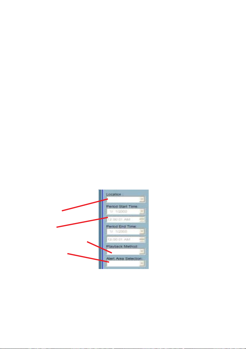
Histogram Area
The Histogram Area in the Preview Mode not only shows the events’ occurred
time and value with red bars, but also tells you the current displayed events
with green bars and the selected event with blue bar. If you want to access the
histogram area, you must change the Area Selection Indicator to the
Histogram Area. You can select a color-inverted region by dragging your mouse
with the left button pressed.
When you release the left button, the color-inverted region will be enlarged to
the whole Histogram Area. This color-inverted region will be the new period
the program is going to display. If you change your mind and don’t want to see
that period, you can cancel it by just pressing the right button of your mouse
with the left button still pressed. If you click on the left button without dragging
it, the display area will show the event page closest to the point you select. The
dark region means there is no video sequence existed in that interval. If you
click on those regions, nothing will happen except a warning dialog.
Using Tools in Playback
Selector tools:
Location selector
Period selector
Playback method selector
Alert area selector.
Location Selector
The location selector is a control that lets you select the camera you want to
see. The location information is the same as the location when you specify in
the monitor program (see Global Settings in the Monitor program section ).
If there is more than one database in the same location, another dialog will
appear (see below). You must select an interval in that dialog. If your selection
is correct, the playback program will automatically switch to that camera and
start displaying.
79
Page 80

Period Selector
Period selector provides you a precise way to choose the start time and the
end time of a new period. The end time should be larger than the start time.
After you give the correct start and end time, clicking on the “Play” button in the
jog dial will play the new period in the Display Area, change the period start and
end time label, the Pull Bar and Histogram Area will change, too. If the selected
period is not present in the database, the data in the period selector will change
to the previous correct start and end time and a warning message will be
displayed.
Playback Method Selector
Full Range
If you select this method, the database will be displayed from the beginning
to the end of this location. Any change in the period selector will take no
effect unless you change this selector to “Time Period”.
Time Period
If you change the playback method to “Time Period”, you can modify the
start and end time in the period selector. When you click on the “Play”
button in the jog dial, the period you select will be displayed.
Events Preview
This method will change the display mode from the normal display mode
to the preview mode.
80
Page 81

Since the program will record the previous start and end time in “Time Period”
and “Events Preview” mode. Any time you want to change the period selector
to see another period, you must change the Playback Method Selector to the
mode you want to use first. Otherwise, the Period Selector will back to the
previous data when you change the Playback Method Selector.
Alert Area Selector
In the Preview Mode, the Playback program only can show the total events
information of one alert window each time. If you want to see the events of the
other two alert area windows, you must change the alert area selector to other
numbers. In the normal display mode, the alert window that the alert area selector
indicates will be highlighted with red rectangle if you checked that window in
the settings dialog. The alert area selector will be changed to alert window
zero, when you change the location selector to another one.
Play Control
Speed Indicator Pause
Play
Step Forward
Stop
For the play control, a jog dial is used to provide the easiest way to control the
displaying video sequence. Except the “Play” button, all other buttons can control
the displaying frame in the normal display mode and the selected displaying
frame in the preview mode.
Play
The “Play” button is an intelligent play interface. The functiony of this button
can vary to fit with different circumstance. In the normal display mode,
click on the “Play” button can restart the displaying video sequence. When
in the preview mode, if you don’t change the data of period selector, clicking
on this button only restarts the selected displaying frame. If the data of the
period selector has been changed, clicking on the “Play” button will restart
all frames to display the first nine events in the new period.
81
Page 82

Stop
When you want to stop the displaying video sequence, you can click on
the “Stop” button. Once you had pressed the “Stop” button, the start point
will be reset to the start of the present period.
Pause
The “Pause” button provides you a way to pause the displaying video
sequence. When the displaying video is paused, click on the “Pause” button
again will continue the video to display.
Step Forward
This button is only valid when the displaying video sequence is paused. It
will display the next frame in that period when you click on the “Step
Forward” button one time.
Fast Play and Slow Play
We support maximum to 16X fast forward play and slow forward play. This
function helps you browse the surveillance database more flexible. If you want
to change the playing speed, you just need to move the speed indicator. To
increase playing speed, move the indicator in the clockwise direction. And to
decrease playing speed, move it in the counterclockwise direction. The current
speed you set will be shown in the second column of status area.
Display Adjustment Toolbox
Using the Display Adjustment Toolbox, you can change the displaying video
sequence to the size you want to see in the normal display mode when you
move the area selection indicator to the display area. Below is the Display
Adjustment Toolbox and its own three elements, i.e. “Zoom In”, “Zoom Out”,
and “Full Screen”.
Zoom In
When you click on the “Zoom In” button one time, the image size in the
display area will be magnified 12.5 percent to the original size. Due to the
limitation of the display area size, the maximum zoom in ratio we support
here is only 2.25:1 for NTSC modulation mode and 1.875:1 for PAL
modulation mode. If you want to see the image in more details, you can use
the full screen function we support in the same toolbox.
82
Page 83

Zoom Out
When you click on the “Zoom Out” button one time, the image size in the
display area will be minified 12.5 percent to the original size. To show the
location and time information completely, the minimum zoom out ratio is
limited in 0.5:1.
Full Screen
When you click on the Full Screen button, the video sequence will be
enlarged to fill the whole screen. You can double click on any place to return
to the original state. When you switch to full screen display, you can press
the “Alt” and “Space” keys together to pop the jog dial to control the
displaying video sequence. Press the same keys again will close the jog dial.
You can also press the “Alt” and “Enter” keys together to switch between the
normal display and full screen display at any time when the program is under
the normal display mode.
Searching Range Adjustment Toolbox
The Searching Range Adjustment Toolbox provides you a faster way to
change the range of the displayed time period. By using this toolbox, you can
browse the database of one location from any 10-second interval over its entire
range. Below is the Searching Range Adjustment Toolbox with its own three
elements: “Zoom In”, “Zoom Out”, and “Full Range”.
Zoom In
Each time you click on the “Zoom In” button in the searching range
adjustment toolbox, the displayed time period will be half in the center of the
original time period until the period is equal to 10 seconds. You can see the
new interval in more details. The scale of pull bar and alert histogram window
changes and the period start and end time change, too. The period selector
will show the new start and end time. And the display area will restart to
display the new period from the new start time.
83
Page 84

Zoom Out
Each time you click on the “Zoom Out” button in the searching range
adjustment toolbox, the displayed time period will be double in the center of
the original time period unless the start time or end time exceed the database
boundary. The scale of pull bar and alert histogram window changes and the
period start and end time change, too. The period selector will show the new
start and end time. And the display area will restart to display the new period
from the new start time.
Full Range
As you click on the “Full Range” button, you will get the same functionality as
if you changed the Playback Method Selector to “Full Range”.
Exporting Toolbox
You can check the database through the the Playback program and also
export the database to other media. Using the ExportingToolbox, you can
export the database to other more portable formats, such as AVI file, bitmap
file or paper. Then you may use windows media player or other program to
browse the exporting data. Under the normal display mode, you can use all
the exporting tools. And under the preview mode, only snapshot and print can
be used. shows the three elements of the Exporting Toolbox:“Transducer”,
“Snapshot”, and “Print”.
Transducer
Using the Transducer tool, you can convert the displayed video sequence to
the an AVI format file. Just click on the “Transducer” button and a dialog box
appears (shown below) asking to confirm transforming a database into an
AVI file.When you click on the “Ok” button, the conversion procedure will be
started.
84
Page 85

The time required to Export data depends on the speed of the computer and
processor that you are using. At any time during the export, you can click on
the “Stop” button in the jog dial to stop the procedure. Then you will get an AVI
file from the start time to the time you clicked the “Stop” button. The exported
AVI filename will be generated automatically and will be listed in the fourth column
of the status area. If you want to change the output directory, you can go to the
Settings Window (See Page 75). To increase the quality of an exported AVI
file, it is suggested to set the video format to normal size, please refer to the
Camera Configurations section (see Page 45).
Snapshot
When you click on the “Snapshot” button one time, the program will export a
bitmap. In the normal display mode, the exporting bitmap is the image shown
in the display area. And in the Preview Mode, it is the image that you
selected through the Frame Selection Indicator. The size of the bitmap will
be the same as that of the image you select. The exported bitmap filename
will be generated automatically and listed in the fourth column of the status
area. If you want to change the output directory, you can go to the Settings
window.
Print
When you click on the “Print” button, a dialog box will be appear. After you
make your selection and send to the printer, the images on the Display Area
will be printed out.
85
Page 86

System Control Toolbox
The System Control Toolbox provides basic operations for the playback
program. The three elements of the system control toolbox:. “Lock Window”,
“Settings”, and “Exit”.
Lock Window
If you want to leave your computer, we suggest either closing the Playback
program, or you can click on the “Lock Window” button to lock the main
window. Once you click this button, the main window will be hidden and the
login dialog will appear. To return to the main window, you need to enter the
admin root password again.
Settings
The settings dialog will pop up when you click the “Settings” button. For more
information about setting this program see the Settings section above.
Exit
The playback program will terminate when you click on the “Exit” button. If
the AVI exporting procedure is running, this procedure will be stopped first.
86
Page 87

Appendix
Frequently Asked Questions
Internet Camera Features
Q: What is an Internet Camera?
A:The Internet Camera is a standalone system connecting directly to an Ethernet
or Fast Ethernet network. It is differs from a conventional PC Camera, the
Internet Camera is an all-in-one system with built-in CPU and web-based
solutions providing a low cost solution that can transmit high quality video images
for monitoring. The Internet Camera can be managed remotely, accessed and
controlled from any PC/Notebook over an Intranet or the Internet from a web
browser.
Q: What is the maximum number of users that can be allowed to access
DCS-2000 simultaneously?
A: The maximum number of users that can log onto the Internet Camera at the
same time is 10. Please keep in mind the overall performance of the transmission
speed will slow down when many users are logged on.
Q: What algorithm is used to compress the digital image?
A: The Internet Camera utilizes H.263+ MPEG4 Short Header Mode image
compression technology providing high quality images. MPEG is a standard for
image compression and can be applied to various web browser and application
software without the need to install extra software.
Q: Can I capture still images from the Internet Camera?
A: Yes you are able to capture still images with the snapshot function from
the software application CD supplied with the Internet Camera.
Internet Camera Installation
Q: Can the Internet Camera be used outdoors?
A: The Internet Camera is not weatherproof. It needs to be equipped with a
weatherproof case to be used outdoors and it is not recommended.
Q: What network cabling is required for the Internet Camera?
A: The Internet Camera uses Category 5 UTP cable allowing 10 Base-T and
100 Base-T networking.
87
Page 88

Q: Can the Internet Camera be setup as a PC-cam on the computer?
A: No, the Internet Camera is used only on an Ethernet or Fast Ethernet network.
The D-Link DSB-C100, DSB-C300, DSC-350 or DSC-350F can be used as a
PC Camera (Webcam).
Q: Can the Internet Camera be connected on the network if it consists of
only private IP addresses?
A: The Internet Camera can be connected to a LAN with private IP addresses.
Q: Can the Internet Camera be installed and work if a firewall exists on
the network?
A: If a firewall exists on the network, port 80 is open for ordinary data
communication. However, since the Internet Camera transmits image data,
the default port 8481 is also required. Therefore, it is necessary to open port
8481 of the network for remote users to access the Internet Camera.
Troubleshooting
Q: I cannot access the Internet Camera from a web browser?
A1: The possible cause might be the IP Address for the Internet Camera is
already being used by another device. To correct the possible problem, you
need to first disconnect the Internet Camera from the network. Then run the
PING utility (follow the instructions in the Appendix - How to Ping Your IP
Address.)
In Windows 95/98/2000 and Windows NT, check that the IP Address of the
Internet Camera is within the same subnet as your workstation.
§ Click Start, Setting, Control Panel, and the Network icon.
§ Select TCP/IP from the Network dialog box and from the TCP/IP
Properties dialog box click on Specify an IP address.
§ If the Internet Camera is situated on a different subnet than your
workstation, you will not be able to set the IP address from this workstation.
To verify make sure the first 3 sections of the IP address of the Internet
Camera corresponds to the first 3 sections of the workstation. Therefore
the IP address of the Internet Camera must be set from a workstation on
the same subnet.
A2: Other possible problems might be due to the network cable. Try replacing
your network cable. Test the network interface of the product by connecting a
local computer to the unit, utilizing a standard Crossover (hub to hub) Cable. If
the problem is not solved the Internet Camera might be faulty.
88
Page 89

Q: Why does the Power LED not light up constantly?
A1: The power supply used might be at fault. Confirm that you are using the
provided power supply, which is DC 12V, for the Internet Camera and verify
that the power supply is well connected.
A2: Another possible reason is the IP Address is located on a different subnet.
To fix the problem, run the PING utility (follow the instructions in the Appendix
How to PING Your IP Address). If the utility returns “no response” or a simila
message, the finding is probably correct and you need to resolve this issue
with a system adminstrator.
Q: Why does the Internet Camera work locally but not externally?
A1: Might be caused from the firewall protection. Check the Internet firewall
with your system administrator. The firewall may need to have some settings
changed in order for the Internet Camera to be accessible outside your local
LAN.
A2: Make sure that the Internet Camera isn’t conflicting with any web server
you may have running on your network.
A3: The default router setting might be a possible reason. Check that the
configuration of the router settings allow the Internet Camera to be accessed
outside your local LAN.
Q: Why does a series of broad vertical white line appear through out the
image?
A: It could be that the CMOS sensor has become overloaded when it has been
exposed to bright lights such as direct exposure to sunlight or halogen lights.
Reposition the Internet Camera into a more shaded area immediately as
prolonged exposure to bright lights will damage the CMOS sensor.
Q: The focus on the Internet Camera is bad, how can I correct it?
A1: Adjust the Internet Camera focus manually as described in “Adjusting the
Internet Camera Focus” in the Appendix section of this manual.
A2: If you have previously changed the supplied CS-type lens, you may have
unintentionally installed a C-type lens without fitting the adaptor first.
Q: Noisy images occur. How can I solve the problem?
A1: The video images might be noisy if the Internet Camera is used in a very
low light environment. To solve this issue you need more lighting.
89
Page 90

Q: The images is of poor quality, how can I improve the image quality?
A1: Make sure that your computers display properties are set to at least 15-
bit color. Using 16 or 256 colors on your computer will produce dithering
artifacts in the image, making the image look as if it has bad quality.
A2: The configuration on the Internet Camera image display is incorrect. Through
the Configuration section of the web management you need to adjust the image
related parameter for improve images such as brightness, contrast, hue and
light frequency. Please refer to the Configuration section for detail information.
How to PING Your IP Address
The PING (Packet Internet Groper) command can determine whether a specific
IP address is accessible by sending a packet to the specific address and waiting
for a reply. It can also provide a very useful tool to confirm if the IP address
conflicts with Internet Camera over the network.
Follow the step-by-step procedure below to utilize the PING command but first
you must disconnect Internet Camera from the network.
Start a DOS window.
Type ping x.x.x.x, where x.x.x.x is the IP address of the Internet Camera.
The replies, as illustrated below, will provide an explanation to the prob
90
Page 91

Reset and Restore
There is a button hidden in the pinhole beside the Ethernet socket. It is
used to reset the system or restore the factory default settings.
Sometimes resetting the system can make the system back to normal
state. If the system still has problems after reset, restore the factory
settings and install again:
RESET: Poke a paperclip or a small tool to click on
the button.
RESTORE: 1. Poke the tool to press on the button continuously.
2. Wait for self-diagnostic to run twice.
3. Withdraw the wrench as soon as the second self-
diagnostic starts.
Reset button.
Restoring the factory defaults will result
in the loss of any previous settings.
Reset or restore the system after power
on.
91
Page 92

I/O Connector
I/O Connector Definition for the Internet Camera
The DCS-2000 provides a general I/O terminal block with one digital input
and one relay switch for device control. Pin 1 and pin 2 can be connected to
an external sensor and the state of voltage will be monitored from the initial
state ‘LOW’. The relay switch of pin 3 and pin 4 can be used to turn on or off
the external device.
The I/O connector provides the physical interface for digital output (DO) and
digital input (DI) that is used for connecting a diversity of external alarm devices
to the Internet Camera such as IR-Sensors and alarm relays.
The digital input is used for connecting external alarm devices and once triggered
images will be taken and e-mailed.
I/O Terminal Block:
1 DI+ INPUT (Max. 50mA, 12VDC)
2 DI- INPUT (Initial state of DI is low)
3 SW_COMMON OUTPUT (open from SW_OPEN at initial state)
4 SW_NOPEN OUTPUT (Max. 1A, 24VDC or 0.5A, 125VAC)
(close with SW_OPEN when set DO to ON)
92
Page 93

Time Zone Table
GMT stands for Greenwich Mean Time, which is the global time that all
time zones are measured from.
93
Page 94
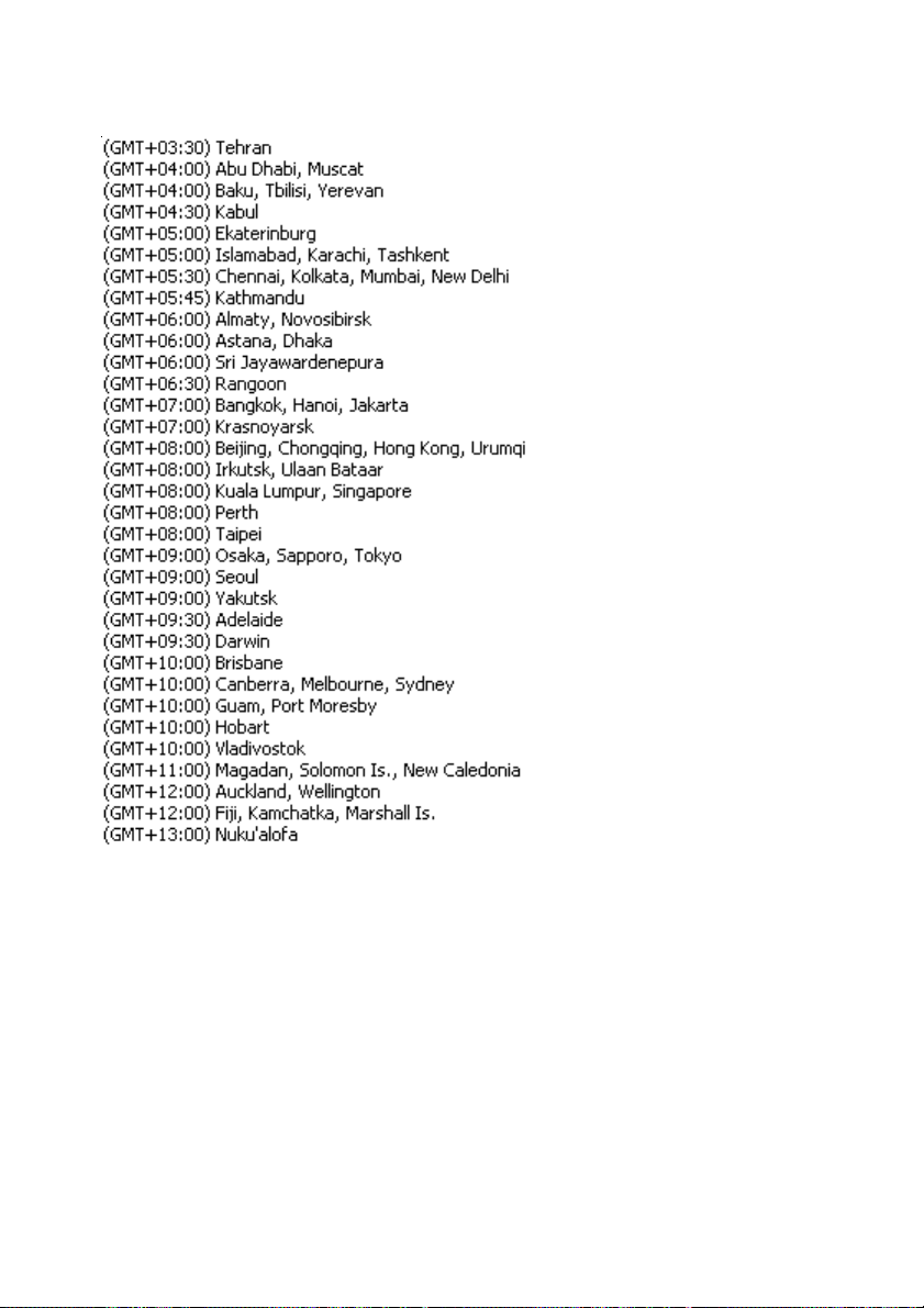
94
Page 95

Adjusting the Cameras Focus
The DCS-2000 Internet Camera features an interchangeable C/CS-type lens
that can be used for different applications as necessary. It supports rotational
focus control so the lens can be adjusted to focus under normal and stable
conditions to maximize the image quality of the Internet Camera.
To adjust the focus of the lens you will need to turn the lens slowly either
clockwise or counter-clockwise until the desired image appears. DO NOT overturn the lens in either direction as it will be out of focus. Unless you want to
substitute the lens DO NOT unscrew more than 1.0mm apart from the Fixed
Lens Assembly.
To help you get the best image quality, keep in mind that while adjusting the
DCS-2000’s focus you can preview the image quality from your Web browser.
Please refer to the diagram below when adjusting the camera lens.
95
Page 96

Fixed Lens Assembly
DO NOT adjust
Camera Lens
Adjust by turning
clockwise or counter-clockwise
Note:
You can further adjust the Internet Camera’s image quality
through the Web Configuration under Configuration > Ad-
vanced > Video. Please refer to Using the DCS-2000 section
for further details.
Warning
Direct exposure to sunlight may cause permanent damage to the
CMOS sensor. Therefore do not expose the Internet Camera’s lens
directly to sunlight. When operation is required in glaring light environment, it is recommended to use an iris lens.
The Internet Camera is designed for indoor usage and if your application requires prolonged exposure to sunlight, a sun visor is recommended to protect the Internet Camera.
96
Page 97

Replacing the Lens
Since the Internet Camera is designed with a CS- mount, the lens equipped
with the Internet Camera can be replaced with any standard C or CS lens
commonly used within the surveillance industry.
Follow the instructions below to replace the supplied lens with any C or CS
type lens.
1. Unscrew the Internet Camera lens
2. When using a C-lens, attach the new lens to a CS-C adapter
3. Screw the new lens onto the Internet Camera. If appropriate, adjust the iris
according to the prevailing light conditions.
4. Refer to Adjusting the Internet Camera Focus on the previous page.
5. Refresh the web browser and monitor the results from the Internet Camera.
97
Page 98

Technical Specifications
Remote management
Configuration and system log can be accessed via Web browser and FTP application
remotely
Networking
Protocol
TCP/IP, HTTP, SMTP, FTP, Telnet, NTP, DNS and DHCP
Ethernet
10BaseT or 100BaseT Fast Ethernet
Video
Algorithm supported
H.263+ (MPEG-4 Short header mode)
Features
Three adjustable image size and quality Intelligent motion detection windows with
flexible bit rate
Audio
24Kbps
Video resolution
Up to 30 fps at 160x120
Up to 30 fps at 320x240
General I/O
1 opto-isolated sensor input(max. 12VDC 50mA)
1 relay output(max. 24VDC 1A, 125VAC 0.5A)
Security
Administrator and user group protected
Password authentication
98
Page 99

Technical Specifications (continued)
LED indicator
Bi-color status indicator
Camera specification
1/3 inch color CMOS sensor
640x480
2.5Lux/F1.4
AGC/AWB
Electronic shutter: 1/60 ~ 1/15000 second
Standard CS mount type lens, 6mm, F1.8
Power
12VDC 1.2A, external power supply
Weight
About 240g
Dimension
135mm(L)x89mm(W)x57mm(H)
Viewing system requirement
Protocol
Standard Internet TCP/IP suite
Operating system
Microsoft Windows XP, 2000, ME or 98SE
Browser
Internet Explorer 5.x or above
99
Page 100

Contacting Technical Support
You can find the most recent software and user documentation on the D-Link website.
D-Link provides free technical support for customers within the United States for the
duration of the warranty period on this product.
U.S. customers can contact D-Link technical support through our web site,
or by phone.
D-Link Technical Support over the Telephone:
(877) 453-5465
24 hours a day, seven days a week.
D-Link Technical Support over the Internet:
http://support.dlink.com
When contacting technical support, please provide the following information:
· Serial number of the unit
· Model number or product name
· Software type and version number
100
 Loading...