


Naza-H
Table of contents
 Loading...
NAZA HELI
Quick Start Guide
V1.06
2013.03.01 Revision
Please strictly follow these steps to mount and connect the NAZA-H system on your helicopter, as well as to
install the Assistant Software on your computer.
The NAZA-H is very sensitive to vibrations and excessive vibration may impact the normal operation of the
system. If you experience excessive vibration on your helicopter, please adjust the rpm of the main rotor to
reduce the vibration or find other causes for the vibration, and then you can continue to fly.
As DJI Innovations has no control over use, setup, final assembly, modification or misuse, no liability shall be
assumed nor accepted for any resulting damage or injury. By the act of use, setup or assembly, the user
accepts all resulting liability. DJI Innovations accepts no liability for damage(s) or injuries incurred directly or
indirectly from the use of this product.
DJI and NAZA-H is registered trademark of DJI Innovations. Names of product, brand, etc., appearing in this
manual are trademarks or registered trademarks of their respective owner companies. This product and
manual are copyrighted by DJI Innovations with all rights reserved. No part of this product or manual shall be
reproduced in any form without the prior written consent or authorization of DJI Innovations. No patent liability
is assumed with respect to the use of the product or information contained herein.
NAZA-H has achieved CE, FCC and RoHS certification.
*This manual is only for basic assembly and configuration; you can obtain more details and advanced
instructions when using the assistant software. To assure you have the latest information, please visit our
website and download the latest manual and current software version.
www.dji-innovations.com
©2012 DJI Innovations. All Rights Reserved. 1 |

Index
INDEX ..................................................................................................................... 2
NAZA-H INTRODUCTION ...................................................................................... 3
PROCEDURE STEPS ............................................................................................ 3
STEP1 ASSEMBLY ................................................................................................ 4
STEP2 SOFTWARE AND DRIVER INSTALLATION ............................................. 5
STEP3 ASSISTANT SOFTWARE USAGE ............................................................ 5
STEP4 DIGITAL COMPASS CALIBRATION ......................................................... 6
STEP5 AUTO TRIM FLIGHT KNOWLEDGE (ONLY FOR FLYBARLESS) .......... 7
STEP6 CONTROL MODE KNOWLEDGE ............................................................. 8
STEP7 TEST FLIGHT ............................................................................................ 9
APPENDIX ............................................................................................................ 10
FIRMWARE & ASSISTANT SOFTWARE UPGRADE ..................................................... 10
PORTS DESCRIPTION ........................................................................................... 11
LED INDICATOR DESCRIPTION .............................................................................. 12
SPECIFICATIONS .................................................................................................. 13
©2012 DJI Innovations. All Rights Reserved. 2 |

NAZA-H Introduction
NO.
Steps
Description
Page
Step1
Assemble
Assemble NAZA-H components and receiver to the
helicopter, and connect the receiver, main controller,
LED Indicator. GPS & Compass module, BEC module
(optional).
Assembly
----4
Step2
Install Software
and Driver
Please download the DJI Driver Installer and the
NAZA-H assistant software from the DJI website and
then install them to your PC.
Software and
Driver Installation
----5
Step3
Use Assistant
Software
Configure the helicopter according to the setup wizard,
including the following procedures: choose receiver
type, set control mode switch, calibration of the remote
control, choose the rotor and the swashplate type, etc.
Configure the common parameters, such as autopilot
parameter, alarm voltage, etc.
Assistant
Software Usage
----5
Step4
Calibrate Digital
Compass
If the GPS module is used, toggle the control mode
switch from Manual Mode to GPS ATTI. Mode to enter
the calibration mode and finish calibration.
Digital Compass
Calibration ----6
Step5
Know the Auto
Trim Flight
Please complete the auto trim flight in calm air
weather, after first assembly and after mechanical
adjustment.
Auto Trim Flight
Knowledge----7
Step6
Know the control
mode
Make sure you have a good understanding about the
working features of the three control modes.
Control Mode
Knowledge----8
Step7
Test Flight
Please strictly follow the procedures during the flight
test for all the flight modes.
Test Flight
----9
The NAZA-H includes Manual Mode, ATTI. Mode and GPS ATTI. Mode (optional). It is a flight control system
designed for all helicopter enthusiasts with the functions of self-leveling, built-in tail gyro and position holding
in the GPS mode, which completely takes the stress out of flying R/C helicopters for both professional and
hobby applications. Standard NAZA-H includes the main controller and LED indicator with optional GPS
module and BEC module. It can be installed in a variety of models, from small to large electric helicopters,
including 450,500,600 and 700 Electric Helicopter.
Procedure Steps
©2012 DJI Innovations. All Rights Reserved. 3 |
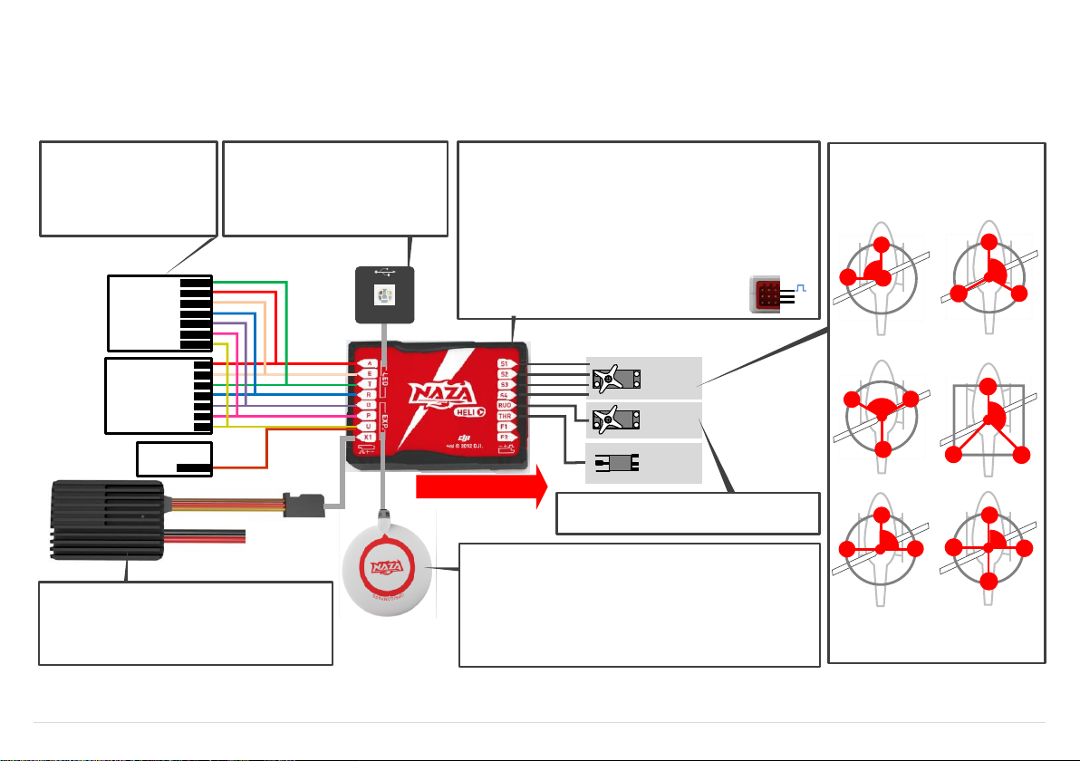
Rudder
Servo
Swashplate
Servo
×3 or 4
ESC
Main Controller(MC)
· Position: the MC is best positioned near the helicopter’s center of gravity,
and make sure all ports are accessible when installing the MC so as to
facilitate wiring.
· Orientation: orient the MC such that the arrow marked on the above, surface
of the MC faces the sky and points directly forward, backward, left or right.
The sides of the MC should be precisely parallel to the helicopter body. DO
NOT MOUNT THE MC UPSIDE-DOWN.
· Mo un t: u se double-sided foam tape for secured installation. Check the
double-sided foam tape or Velcro regularly to ensure that the MC is securely
positioned.
· Note: In three-pin ports, pins near the nicks are signal pins.
MC is NOT water-proof or oil-proof.
LED Indicator
· Mo u nt : moun t the LED module t o the
helicopter, and make sure that you can
see LED indicator during flight.
· Connect: a USB interface Is for configuration
and firmware upgrade by connecting to PC.
Front of MC
+
-
Battey
(Optional)GPS& Compass Module
· Position: mount it on the tail boom, between the head-rotor and the tail-rotor.
The compass is sensitive to magnetic interference, so position the module at
least 20 cm from servos and 30 cm from electric motors. The GPS should not
be close to the main rotor head because rotor blades can interfere with GPS
satellite signal, the farther from the center of the rotor disk, the better.
· Orientation: the NAZA logo marked on the GPS should face the sky, with the
orientation arrow pointing to the helicopter nose direction.
· Mount: use double-sided foam tape for secured installation.
(Optional)BEC
· Conne ct: connect the BEC to the right ports on MC
supplying power for NAZA-H and other electronic devices.
· Toggle switch: slide the switch to 7.4V if high-voltage
servo is used, else to 5.8V if low-voltage servo is used.
R/C System
· Mount: mount the receiver to the
helicopter.
· Connect: connect the receiver to
the right ports on MC.
R/C Receiver
(JR)
R/C Receiver
(Futaba / Hitec)
Futaba S-Bus
S-Bus
1
2
3
4
5
6
7
RUDD
THRO
AILE
ELEV
GEAR
AUX1
AUX2
Optional
Rudder Servo
· Do not connect the rudder servo until the servo type
has been selected in assistant software.
Swash plate Servo
NAZA-H can support the following Sw ash
plate types
Please choose the Swash plate type in the
as si stant s oftwa re acc or ding to your
helicopter.
S2
S1
90
o
S3
H1
S2
S1
S3
120
o
H3
S2
S1
S3
120
o
HR3
S2
S1
S3
140
o
H140
S2
S1
S3
90
o
HE3
S4
S2
S1
S3
90
o
H4
Step1 Assembly
Install the main controller, LED module and receiver to the helicopter, and connect according to the following diagram. GPS &Compass(optional), BEC module (optional).
©2012 DJI Innovations. All Rights Reserved. 4 |
Loading...