


M210 RTK
Table of contents
 Loading...
MATRICE 200 SERIES V2
M210 V2 / M210 RTK V2
2019.04
v1.2
User Manual
2
©
2019 DJI All Rights Reserved.
Using This Manual
Legends
Warning Important Hints and Tips Reference
Before Flight
The following materials have been produced to help users make full use of the MATRICE
TM
210 V2 /
Matrice 210 RTK V2.
1. In the Box
2. Disclaimer and Safety Guidelines
3. Quick Start Guide
4. Intelligent Flight Battery Safety Guidelines
5. User Manual
Watching all the tutorial videos and reading the Disclaimer and Safety Guidelines before ight is
recommended. Afterwards, prepare for your rst ight by using the Quick Start Guide. Refer to this
manual for more comprehensive information.
Download the DJI Pilot app
The DJI Pilot app is required if using a mobile device connected to the remote
controller. Search for Scan the QR code or visit https://m.dji.net/djipilot_enterprise to
download the app. DJI Pilot supports Android 5.0 or later.
* For increased safety, the ight is restricted to a height of 30 m and distance of 50 m when not connected or logged
into the app during ight, including DJI Pilot and all apps compatible with DJI aircraft.
Download the DJI Assistant 2 for Matrice
Download and install the ASSISTANT
TM
2 for Matrice before use.
http://www.dji.com/matrice-200-series-v2/info#downloads
Searching for Keywords
Search for keywords such as “battery” and “install” to find a topic. If you are using Adobe
Acrobat Reader to read this document, press Ctrl+F on Windows or Command+F on Mac to
begin a search.
Navigating to a Topic
View a complete list of topics in the table of contents. Click on a topic to navigate to that section.
Printing this Document
This document supports high resolution printing.

©
2019 DJI All Rights Reserved.
3
Contents
Using This Manual
2
Legends 2
Before Flight 2
Download the DJI Pilot app 2
Download the DJI Assistant 2 for Matrice 2
Product Prole
6
Introduction 6
Feature Highlights 6
Assemble the Aircraft 7
Preparing the Remote Controller 9
Aircraft Diagram 10
Remote Controller Diagram 11
Aircraft
14
Prole 14
Flight Mode 14
Flight Status Indicator 15
Vision System and Infrared Sensing System 16
Return-to-Home (RTH) 20
Center of Gravity Calibration 25
Spotlight Pro 25
Flight Recorder 25
Attaching and Detaching the Propellers 25
DJI Intelligent Flight Battery 26
D-RTK (for M210 RTK V2) 31
DJI AirSense 32
Components at the Rear of the Aircraft 33
Remote Controller
37
Remote Controller Prole 37
Preparing the Remote Controller 37
Mounting the Monitor to the Remote Controller 39
Remote Controller Operations 39
Linking the Remote Controller 45
Mounting the Control Stick Covers 46

4
©
2019 DJI All Rights Reserved.
Gimbal and Camera
48
Camera 48
Gimbal 49
DJI Pilot App
52
Manual Flight 52
Mission Flight 56
Album 58
DJI FlightHub 58
Menu 58
Flight
60
Flight Environment Requirements 60
GEO (Geospatial Environment Online) System 60
Flight Restrictions 61
GEO Unlocking 64
Preight Checklist 64
Calibrating the Compass 64
Stop the Motor Mid-ight 66
Starting/Stopping the Motors 66
Flight Test 67
Appendix
70
Specications 70
Firmware Update 72
Using the Zenmuse XT Gimbal and Camera 73
Dual Downward Gimbals 74
Using the Upward Gimbal and GPS Kit 74
Carrying Box Descriptions 75

©
2019 DJI All Rights Reserved.
5
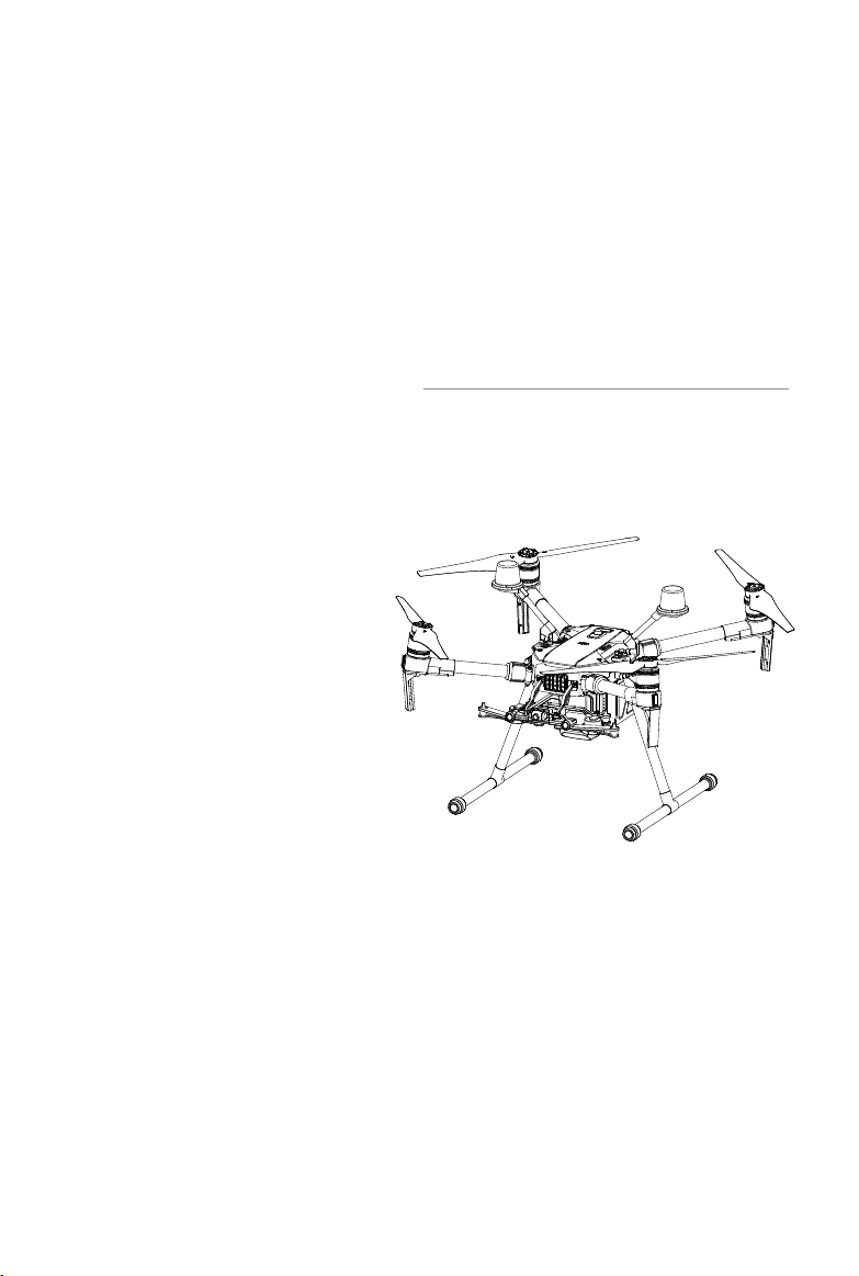
Product Prole
This chapter describes the features of
the Matrice 210 V2/Matrice 210 RTK
V2, shows how to assemble the aircraft,
and contains diagrams of the aircraft
and remote controller with component
explanations.

6
©
2019 DJI All Rights Reserved.
Product Prole
Introduction
The Matrice 210 V2/Matrice 210 RTK V2 (M210 V2/M210 RTK V2) is a powerful aerial imaging
system with class-leading agility and speed, redundant components for maximum reliability,
and smart features that make performing complex tasks easy. The aircraft’s visual sensors*
enable enhanced hovering precision even when flying indoors or in environments where GNSS
is unavailable. Gimbal cameras can be easily exchanged to suit your application's needs. Dual
frequency transmission system makes HD video downlink more stable and efcient.
* The Vision and Infrared Sensing Systems are affected by surrounding conditions. Read the related section to
learn more.
Feature Highlights
The ight controller provides a safe and reliable ight experience. A ight recorder stores critical
data from each ight. Dual IMUs and barometers design provides redundancy. The aircraft can
hover and fly in extremely low altitude and indoor environments, and provides multi-directional
obstacle sensing and vision positioning functions.
The built-in AirSense makes you aware of nearby aircraft in the surrounding airspace to ensure
safety. The safety beacons on both the top and the bottom of the aircraft allow the aircraft to be
identied at night or in low light conditions. The airframe design gives the aircraft an IP43 Ingress
Protection, in accordance with the global IEC 60529 standard.
The TimeSync system continuously aligns the ight controller, camera, GPS module, RTK module
for the M210 RTK V2, DJI payloads such as X4S, X5S or X7, as well as onboard accessories via the
Payload SDK or Onboard SDK at the microsecond level. It meets SDK developers’ requirements on
time precision.
The low-latency long range (up to 5 mi (8 km), FCC) HD downlink is powered by DJI OCUSYNC
TM
2.0. Support of 2.4 GHz and 5.8 GHz ensures a more reliable connection in environments with more
interference. The AES-256 encryption keeps your data transmission secure so you can be sure that
your critical information stays safe.
An advanced power management system along with dual batteries ensures power supply and
enhances ight safety. Without a payload, the M210 RTK V2 has a ight time of up to 33 minutes
with standard batteries (TB55), while the M210 V2 has up to 34 minutes of ight time.
The camera unit is now independent from image processor so that you have the exibility to choose
the perfect gimbal and camera system (including ZENMUSE
TM
X7/X5S/X4S/XT*/XT2, and Z30) for
each of your application. This means that regardless of which camera you choose, you have the
same powerful processing backing it. The M210 V2/M210 RTK V2 can support an upward gimbal**,
a single downward gimbal (connected to Gimbal Connector I) or dual downward gimbals. It is
equipped with many expansion ports to broaden its applications. The M210 RTK V2 has a built-in
DJI D-RTK
TM
2 air system, which provides more accurate heading data for positioning.***
* The Zenmuse XT Gimbal Adapter is required when mounting the Zenmuse XT gimbal to the aircraft.
** When using an upward gimbal with the M210 V2, an external GPS Kit connected through the expansion port is
required.
*** When using the M210 RTK V2, more accurate positioning data can be achieved when using a DJI D-RTK 2
High Precision GNSS Mobile Station for Matrice Series. If the data transmission signal between the aircraft and
the mobile station is weak, it is recommended to use post-processed kinematic (PPK) technology.
©
2019 DJI All Rights Reserved.
7
MATRICE 200
SERIES V2 User Manual
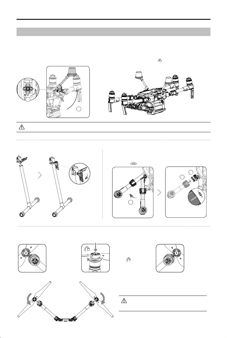
Installing the Landing Gears Unfolding the Aircraft
1
2
3
Unfold the frame arm, slide the arm lock to the end of the frame
arm, then rotate it about 90° until the silver line lies within the
range of the
icon.
Unfold the D-RTK antennas and then turn the knob tightly in the direction indicated by the lock icon .
Assemble the Aircraft
This manual uses the M210 RTK V2 and Zenmuse Z30 as an example to demonstrate setup and usage.
Unfolding the D-RTK Antennas (for M210 RTK V2 only)
Mounting the Propellers
Propellers
without silver
rings go on
motors without
any marks.
Press the propeller down
onto the mounting plate
and rotate in the lock
direction
until secure.
Propellers
with silver
rings go on
motors with
the same
color marks.
Check that the propellers are secure
before each ight.
For the aircraft to take off, the D-RTK antennas must be fully unfolded and securely locked.
1
2

8
©
2019 DJI All Rights Reserved.
MATRICE 200
SERIES V2 User Manual
Mounting the Gimbal and Camera
Make sure to press down the gimbal detachment button when rotating the gimbal lock to
remove the gimbal and camera. The gimbal lock should be fully rotated when removing the
gimbal for the next installation.
Mounting the Intelligent Flight Batteries
Insert a pair of batteries.
Press once to check the battery level.
Press again and hold until the batteries turn on or off.
Press the Gimbal
Detachment button
to remove the cover.
Align the white
and red dots and
insert the gimbal.
Rotate the gimbal
lock to the locked
position.
Only use battery slot B when using one battery to supply power. In this case, the aircraft
can only be powered on, but cannot take off.
If for any reason only one battery is available during ight, land the aircraft immediately
and replace the batteries as soon as possible. In this case, the gimbal connectors and
the ports at rear of the aircraft cannot supply power to their connected devices.
Make sure to use the included TB55 batteries. DO NOT use any other type of batteries.
Removing the Intelligent Flight Battery
Make sure to press the battery removal button when removing the battery.
Gimbal Connector II Gimbal Connector I
Zenmuse XT Zenmuse X4S/X5S/X7/XT2/Z30
Zenmuse Z30 Zenmuse X4S/X5S/X7/XT/XT2
11
2 3
Low
High
A
B
©
2019 DJI All Rights Reserved.
9
MATRICE 200
SERIES V2 User Manual
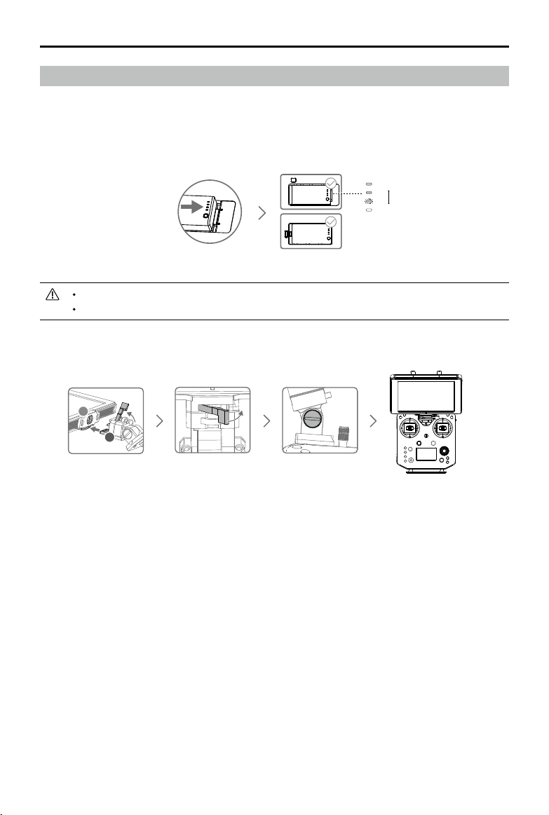
Preparing the Remote Controller
Mounting Monitor and Remote Controller Batteries
CRYSTALSKY
TM
monitors and the remote controller use the same batteries.
Put the battery into the Battery Slot, then slide it to the end until you hear a click.
Press the Battery Release Button before removing the battery.
Press the Battery Level Button once to check the battery level.
Mounting the Monitor to the Remote Controller
Low
High
Lock the Mounting
Bracket.
Use a coin or the
screwdriver included to
adjust the tightness of
the tilt axis.
Ensure that Part B is
unlocked. Connect
Part B to Part A.
A
B
10
©
2019 DJI All Rights Reserved.
MATRICE 200
SERIES V2 User Manual
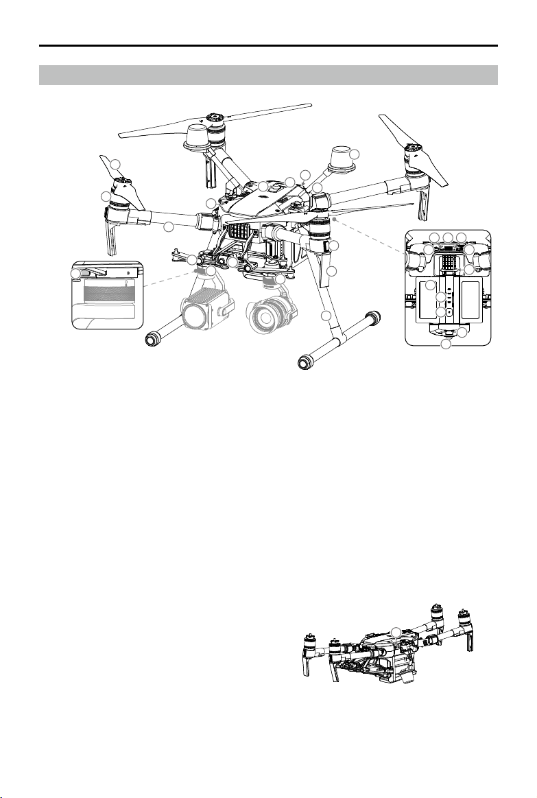
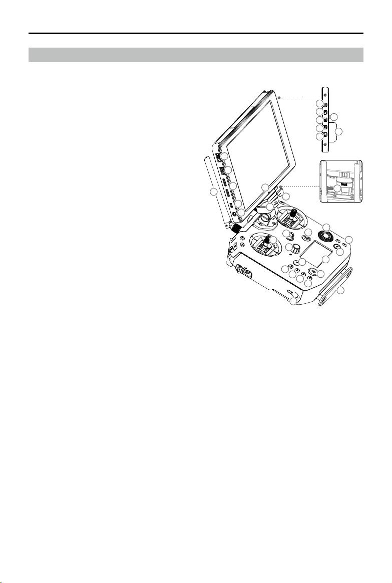
Aircraft Diagram
Folded
1. FPV Camera
2. Forward Vision System
3. DJI Gimbal Connector v2.0 (DGC2.0) I
4. DJI Gimbal Connector v2.0 (DGC2.0) II
5. Gimbal Detachment Button
6. Frame Arms
7. Motors
8. Propellers
9. ESC LEDs
10. Transmission Antennas
11. Landing Gears
12. Upward Gimbal Mounting Position
13. Beacons*
14. Upward Infrared Sensor
15. Aircraft Status Indicators
16. D-RTK Mounting Bracket**
17. D-RTK Antennas**
5
6
7
8
2
4
1
3
11
10
9
17
15
14
13
12
16
18
19 20 21
22
23
24
25
26
27
13
28
18. Extended Power Port (XT30)
19. USB Mode Switch
20. USB Port
21. Linking Button and Indicator
22. Expansion Ports
23. Battery Removal Button
24. Intelligent Flight Batteries
25. Battery Level Indicators
26. Power Button
27. Downward Vision System
28. microSD Card Slot
* DO NOT look directly at the beacons when they are in use to avoid damage to your eyes.
** Included in the M210 RTK V2 aircraft only.
©
2019 DJI All Rights Reserved.
11
MATRICE 200
SERIES V2 User Manual
Remote Controller Diagram
1. HDMI Port
Output HDMI video signal.
2. USB Port
Supported extended device, e.g. U disk.
3. microSD Card Slot
Provides extra storage space for the display
device, maximum card size is 128 GB.
4. Micro USB Port
Use a Micro USB cable to connect to the
remote controller when in use, or to the PC to
congure parameters via DJI Assistant 2.
5. Headphone Jack
6. Light-Sensitive Port
Built-in light-sensitive sensor.
7. Power Button
8. Custom Button (F1)
9. Setting Button
10. Custom Button (F2)
11. Back Button
12. Battery Release Button
13. WB37 Intelligent Battery
14. Antennas
Relay aircraft control and video signal.
15. Monitor Mounting Bracket
Used to mount the DJI CrystalSky monitor.
16. USB Port (Reserved Port)
17. Control Sticks
Control the orientation and movement of the
aircraft.
18. Strap Hook
19. Focus Adjustment Knob
Rotate to set the focal length.
20. Return-to-Home (RTH) Button
Press and hold to initiate RTH.
21. Power Port
Connect to the Charger to charge the battery
of the remote controller.
22-25. Reserved Buttons
26. Pause Button
Press once and the aircraft will brake and hover.
27. Power Button
Used to turn the remote controller on and off.
28. Remote Controller Display
Shows information about the aircraft and
camera.
29. Camera Setting Dial
When using an X4S, X5S, X7 or Z30, turn the
dial to adjust the EV. When using an XT2 or
XT, turn the dial to select palette.
30. Customizable Button Settings Menu
Press to set Customizable Button functions in
the DJI Pilot app.
31. Customizable Buttons (BA-BH)
Customizable through the DJI Pilot app.
15
7
8
10
9
11
13
12
16
2
5
4
1
3
14
6
17
18
18
19
20
21
22
23
24
25
26
27
28
29
30
31
32
12
©
2019 DJI All Rights Reserved.
MATRICE 200
SERIES V2 User Manual
33
34
35
36
37
38 39 40 41
42
43
44
45
46
4747
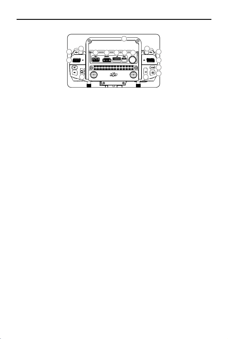
32. Support Rig
33. Left Lever
Customizable through the DJI Pilot app.
34. Left Dial (Gimbal Pitch)
Controls gimbal pitch.
35. Flight Mode Switch
Switch between P-mode, S-mode, and
A-mode.
36. Handle Bar
37. USB Port (for Mobile Device Connection)
Connection to mobile device for DJI Pilot app
if used a third party mobile device.
38. HDMI A Port (for Video Output)
Output HDMI signal to an HDMI monitor.
39. CAN Bus Port (Extension Port)
Reserved port used to connect external
devices.
40. Micro USB Port
Connect to the DJI Assistant 2 for Matrice to
update rmware.
41. SDI Port (for Video Output)*
Output SDI video signal.
42. Right Lever
Customizable through the DJI Pilot app.
43. Right Dial
Used to control gimbal pan.
44. Auto Focus Button
Press to focus automatically.
45. Record Button
Press to start recording video. Press again to
stop recording.
46. Shutter Button
Press to take a photo. Photos can also be
captured during video recording.
47. Customizable Buttons (C1-C4)
Customizable through the DJI Pilot app.
* For better image transmission, a 75Ω coaxial cable is
required for SDI video signal output. Make sure to use
a coaxial cable with good electromagnetic shielding
performance to avoid signal interference which will
degrade the flight distance. Additionally, disable the
video output in the Image Transmission Settings in the
app when the display device is disconnected.
Aircraft
This section describes the features of
the Flight Controller, Vision System, and
the Intelligent Flight Battery.
14
©
2019 DJI All Rights Reserved.
Aircraft
Prole
The M210 V2/M210 RTK V2 aircraft includes a flight controller, a communication system, vision
systems, a propulsion system and an Intelligent Flight Battery. This section describes the functions
of these components.
Flight Mode
The following ight modes are available for the aircraft:
P-mode (Positioning) :
P-mode works best when the GPS signal is strong. The aircraft utilizes the GPS / RTK module
(for the M210 RTK V2 only) and Forward and Downward Vision Systems to locate itself,
automatically stabilize, and navigate between obstacles.
When the Forward Vision System is enabled and lighting conditions are sufcient, the maximum
flight attitude angle is 25°. When forward obstacle sensing is disabled, the maximum flight
attitude angle is 30°.
When the GPS signal is weak and lighting conditions are too dark for the Forward and
Downward Vision Systems, the aircraft will only use its barometer for positioning to control
altitude.
Note: P-mode requires larger stick movements to achieve higher speeds.
S-mode (Sport):
The aircraft uses GPS for positioning. As Forward and Downward Vision Systems are disabled,
the aircraft will not be able to sense and avoid obstacles when in Sport Mode.
Note: Aircraft responses are optimized for agility and speed making it more responsive to stick
movements.
A-mode (Attitude):
When neither the GPS nor the Vision Systems are available, the aircraft will only use its barometer
for positioning to control the altitude.
The Forward Vision System is disabled in S-mode (Sport), which means the aircraft will
not be able to automatically avoid obstacles in its ight path. Be vigilant and stay clear
of nearby obstacles.
The aircraft’s maximum speed and braking distance are signicantly increased in S-mode
(Sport). A minimum braking distance of 164 feet (50 meters) is required in windless
conditions.
The aircraft’s responsiveness is signicantly increased in S-mode (Sport), which means a small
stick movement on the remote controller will translate into a large travel distance of the aircraft.
Be vigilant and maintain adequate maneuvering space during ight.
Use the Flight Mode switch on the remote controller to select aircraft ight modes.
Atti Mode Warning
The aircraft will enter A-mode in the following two instances:
Passive: When there is weak GPS signal or when the compass experiences interference where the
Vision System is unavailable.
Active: Users toggle the ight mode switch to A-mode.
©
2019 DJI All Rights Reserved.
15
MATRICE 200
SERIES V2 User Manual
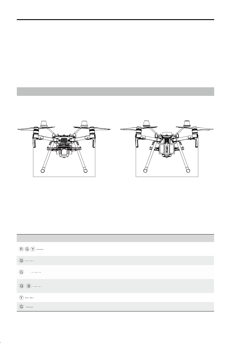
Flight Status Indicator
The aircraft features Front LEDs, Rear LEDs, and Aircraft Status Indicators. The positions of these
LEDs are shown in the gure below:
The Front LEDs show the orientation of the aircraft. Front LEDs glow solid red when the aircraft is
turned on to indicate the front (or nose) of the aircraft. Front and rear LEDs can be turned off in the DJI
Pilot app. The Aircraft Status Indicators communicate the system status of the ight controller. Refer to
the table below for more information about the Aircraft Status Indicators. The Front LEDs, Rear LEDs,
and Aircraft Status Indicators can be turned off in the DJI Pilot app for unobtrusive drone operations.
Aircraft Status Indicator Description
Normal
Red, green, and yellow
ashes
Turning On and Self Diagnostic Testing
Slow green ashing P-mode with GPS*
×2 Two green ashes
P-mode with Forward and Downward Vision
Systems*
Alternating green and
blue ashing
The RTK function of the M210 RTK V2 is enabled
and RTK data is used.
Slow yellow ashing A-mode (no GPS and vision positioning)
Fast green ashing Braking automatically after obstacle detected
Front LEDs
Aircraft
Status
Indicators
Rear LEDs
In A-mode, the Vision System and some advanced features are disabled. Therefore, the aircraft
cannot position or auto-brake in this mode and is easily affected by its surroundings, which may
result in horizontal shifting. Use the remote controller to position the aircraft.
Maneuvering the aircraft in A-mode can be difcult. Before switching the aircraft into A-mode, make
sure you are comfortable ying in this mode. DO NOT y the aircraft too far away as you might lose
control and cause a potential hazard.
Avoid ying in areas where GPS signal is weak, or in conned spaces. The aircraft will otherwise be
forced to enter A-mode, leading to potential ight hazards, please land it in a safe place as soon as
possible.
* Slow green ashes indicate P-mode, and fast green ashes indicate S-mode.
16
©
2019 DJI All Rights Reserved.
MATRICE 200
SERIES V2 User Manual
Warning
Fast yellow ashing Remote Controller Signal Lost
Slow red ashing Low Battery Warning
Fast red ashing Critical Low Battery Warning
Red ashing for 5 seconds
(when performing CSC)
IMU Error
—
Solid Red Critical Error
Fast alternating red and
yellow ashing
Compass Calibration Required
Alternating red and green
ashing
The RTK function of the M210 RTK V2 is enabled
but RTK data is unavailable.
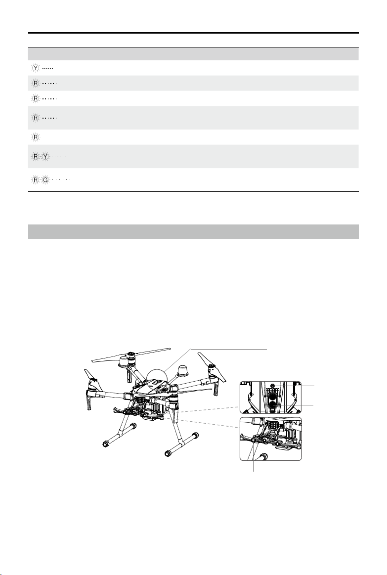
Vision System and Infrared Sensing System
The main components of the Vision System are located on the front and bottom of the aircraft, in-
cluding [1] [3] stereo vision sensors and [2] two ultrasonic sensors. The Vision Sys tem uses ultra-
sound and image data to help the aircraft maintain its current position, enabling precision hovering
indoors or in environments where a GPS signal is not available. The Vision System constantly scans
for obstacles, allowing the aircraft to avoid them by going over, going around, or hovering.
The Infrared Sensing System consists [4] of two infrared modules on top of the aircraft. These scan
for obstacles on top side of the aircraft and is active in certain ight modes.
[2]
[4]
[3]
[1]
©
2019 DJI All Rights Reserved.
17
MATRICE 200
SERIES V2 User Manual
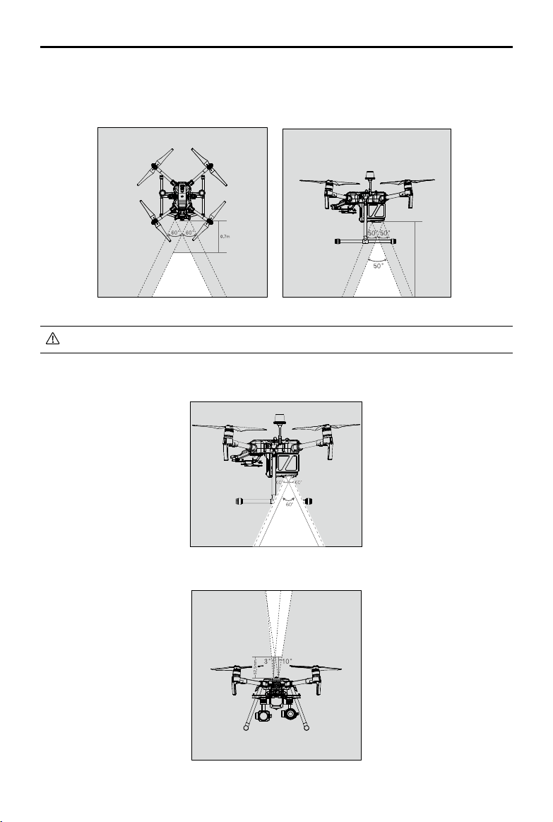
Detection Range
The detection range of the Vision System is depicted below. Note that the aircraft cannot sense
and avoid obstacles that are not within the detection range.
Ultrasonic sensor detection range is depicted below.
Infrared Sensing System detection range is depicted below.
The aircraft cannot detect objects in low-light conditions. Please y with caution.
10m

18
©
2019 DJI All Rights Reserved.
MATRICE 200
SERIES V2 User Manual
Calibration
The Vision System cameras installed on the aircraft are factory calibrated. If the aircraft experiences
a collision, however, it may require calibration via DJI Assistant 2 for Matrice. Connect the aircraft to
a computer and calibrate the Vision System cameras when prompted in DJI Pilot.
1. Power on the Intelligent Flight Battery and slide the USB Mode Switch right.
2. Connect the aircraft and the PC with a USB to USB cable. The USB extension cable included in
the package can be used if the USB to USB cable is too short for connection.
3. Launch DJI Assistant 2 for Matrice and log in with a DJI account.
4. Click M200 V2 SERIES and the calibration button.
1
Point the aircraft toward the screen
2
Align the boxes
3
Pan and tilt the aircraft
If using a laptop for calibration, it is recommended to remove the landing gear before
calibrating the downward vision system. Otherwise, the rectangle produced by the vision
system may not be aligned with the boxes on the screen as the aircraft is farther from the
screen.
DO NOT power off or unplug the USB cable after calibration. Wait for data calculation.
Follow the steps below to calibrate the camera.
Using the Vision System
The Vision System is activated automatically when the aircraft is turned on. No further action is
required. The Downward Vision System enables precision hovering indoors or in environments where
GPS signal isn't available.
©
2019 DJI All Rights Reserved.
19
MATRICE 200
SERIES V2 User Manual
Follow the steps below to use the Downward Vision System:
1. Ensure the aircraft is in P-mode and place the aircraft on a at surface. Note
that the Downward Vision System cannot work properly on surfaces without
clear pattern variations.
2. Turn on the aircraft. The aircraft will hover in place after takeoff. The aircraft
status indicators will ash green twice, which indicates the Downward Vision
System is working.
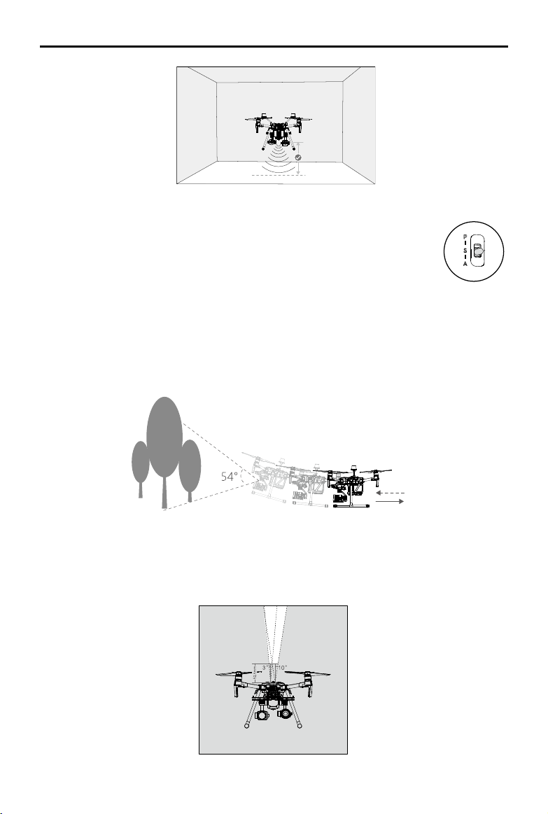
Assisted Braking from Obstacle Sensing
Powered by the Forward Vision System, the aircraft is able to actively brake when obstacles are
detected in front. Obstacle Sensing works best when lighting is adequate and the obstacle is
clearly textured. The aircraft must y at no more than 34 mph (54 kph) with a maximum pitch angel
of 25° to allow for sufcient braking distance.
Using Infrared Sensing System
The Infrared Sensing System can only be used to avoid large, diffuse, and reflective obstacles
(reectivity >10%). Please be mindful of blind spots (Grey) of the Infrared Sensing System.
10 m
20
©
2019 DJI All Rights Reserved.
MATRICE 200
SERIES V2 User Manual
The performance of your Vision System and Infrared Sensing System is affected by the surface
being own over. Ultrasonic sensors may not be able to accurately measure distances when
operating above sound-absorbing materials and the cameras may not function correctly in
suboptimal environments. The aircraft will switch from P-mode to A-mode automatically if neither
GPS nor Vision System and Infrared Sensing System are available. Operate the aircraft with
great caution in the following situations.
The Vision System will be disabled when:
a) Flying over monochrome surfaces (e.g. pure black, pure white, pure red, pure green).
b) Flying over highly reective surfaces.
c) Flying over water or transparent surfaces.
d) Flying over moving surfaces or objects.
e) Flying in an areas where the lighting changes frequently or drastically.
f) Flying over extremely dark (lux < 15) or bright (lux > 100,000) surfaces.
g) Flying over surfaces without clear patterns or texture.
h) Flying over surfaces with identical repeating patterns or textures (e.g. tiling).
i) Flying at high speeds of over 31 mph (50 kph) at 2 meters or over 11 mph (18 kph) at
1 meter.
The Ultrasonic sensors will be disabled when:
a) Flying over surfaces that can absorb sound waves (e.g. thick carpet).
b) Flying over inclined surfaces that will deect sound waves away from the aircraft.
The Infrared be disabled when:
a) Flying over obstacles with too small effective infrared reective surface.
b) DO NOT cover the protective glass of the infrared module. Keep it clean and undamaged.
Keep sensors clean at all times. Dirt or other debris may adversely affect their effectiveness.
Vision System is only effective when the aircraft is at altitudes of 0.3 to 10 meters.
The Vision System may not function properly when the aircraft is ying over water.
The Vision System may not be able to recognize pattern on the ground in low light
conditions (less than 100 lux).
Do not use other ultrasonic devices with frequency of 40 KHz when Vision System is in
operation.
Keep away from animals while operating the aircraft, as the ultrasonic sensors emit high-
frequency sounds which may disturb them.
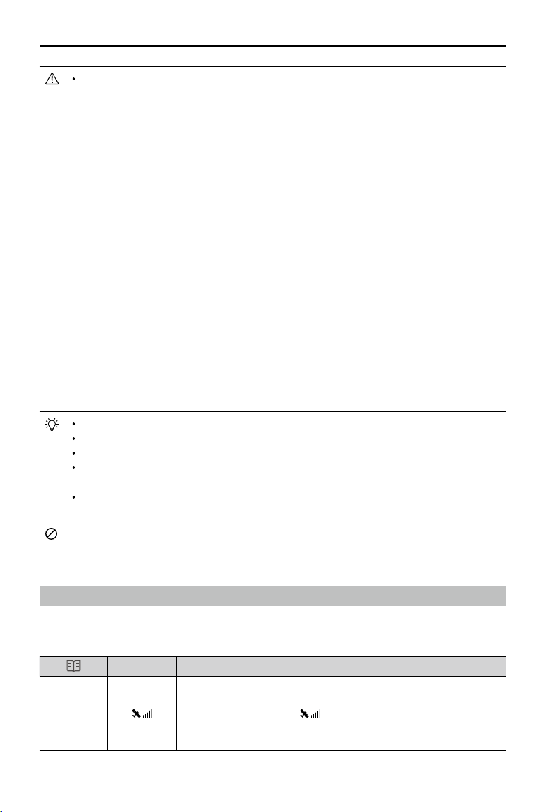
Return-to-Home (RTH)
The Return-to-Home (RTH) function brings the aircraft back to the last recorded Home Point when
there is a strong GPS signal. There are three types of RTH: Smart RTH, Low Battery RTH, and
Failsafe RTH. This section describes these three RTH types in detail.
GPS
Description
Home Point
If a strong GPS signal was acquired before takeoff, the Home Point is
the location from which the aircraft launched. The GPS signal strength is
indicated by the GPS icon
. Less than 4 bars is considered a weak
GPS signal. The aircraft status indicator will blink green rapidly when the
home point is recorded.
©
2019 DJI All Rights Reserved.
21
MATRICE 200
SERIES V2 User Manual
The aircraft can sense and avoid obstacles when the Forward Vision System is enabled and
lighting conditions are sufcient. The aircraft will automatically ascend to avoid obstacles and
descend slowly as it returns to the home point. To ensure the aircraft returns home while facing
forward, it cannot rotate or y left and right during RTH while the Forward Vision System is
enabled.
Smart RTH
Use the RTH button on the remote controller and follow the on-screen instructions when GPS is
available to initiate Smart RTH. The aircraft will then automatically return to the last recorded Home
Point. Use the remote controller to control the aircraft’s speed or altitude to avoid a collision during
the Smart RTH process. Press and hold the Smart RTH button once to start the process, and press
the Smart RTH button again to terminate the procedure and regain full control of the aircraft.
Low Battery RTH (Can be turned off in DJI Pilot app)
The low battery level failsafe is triggered when the DJI Intelligent Flight Battery is depleted to a point
that may affect the safe return of the aircraft. Users are advised to return home or land the aircraft
immediately when prompted. The DJI Pilot app will display a notice when a low battery warning is
triggered. The aircraft will automatically return to the Home Point if no action is taken after a ten-
second countdown. The user can cancel the RTH procedure by pressing the RTH button on the
remote controller. The thresholds for these warnings are automatically determined based on the
aircraft’s current altitude and distance from the Home Point. If the RTH procedure is cancelled
following a low battery level warning the Intelligent Flight Battery may not have enough charge for
the aircraft to land safely, which may lead to the aircraft crashing or being lost.
The aircraft will land automatically if the current battery level can only support the aircraft long
enough to descend from its current altitude. The user cannot cancel the auto landing but can use
the remote controller to alter the aircraft’s orientation during the landing process.
The Battery Level Indicator is displayed in the DJI Pilot app, and is described below:
12:29
Remaining ight time
Sufcient battery
level (Green)
Battery level Indicator
Power required to
return home (Yellow)
Critical Low battery
level warning
Low battery
level warning
Auto landing (Red)
H
22
©
2019 DJI All Rights Reserved.
MATRICE 200
SERIES V2 User Manual
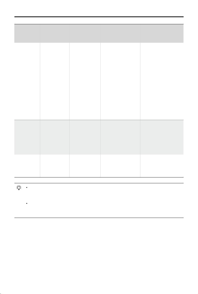
Battery
Level
Warning
Remark
Aircraft Status
Indicator
DJI Pilot App Flight Instructions
Low battery
level
warning
Battery power
is low. Land
the aircraft.
Aircraft status
indicator blinks
RED slowly.
Tap “Go-home” to
have the aircraft
return to the Home
Point and land
automatically, or
“Cancel” to resume
normal ight. If no
action is taken,
the aircraft will
automatically go
home after 10
seconds. Remote
controller will sound
an alarm.
If RTH is selected, the
aircraft will y back
to the Home Point
automatically and
Landing Protection*
will be triggered. Users
can regain control
during RTH. NOTE:
The low battery level
warning will not appear
again after users regain
control.
Critical Low
battery level
warning
The aircraft
must land
immediately.
Aircraft status
indicator blinks
RED quickly.
The DJI Pilot app
display will flash red
and the aircraft will
start to descend. The
remote controller will
sound an alarm.
Allow the aircraft to
descend automatically
and trigger Landing
Protection*.
Estimated
remaining
ight time
Estimated
remaining time is
based on current
battery level.
N/A N/A N/A
When the Critical Low battery level warning is triggered and the aircraft begins to land
automatically, push the left stick upward to make the aircraft hover at its current altitude,
giving you an opportunity to navigate to a more appropriate landing location.
The colored zones and markers on the battery level indicator bar reect the estimated
remaining ight time. They are automatically adjusted according to the aircraft’s current
location and status.
Failsafe RTH
If the Home Point was successfully recorded and the compass is functioning normally, Failsafe RTH
will be automatically activated if the remote controller signal is lost for more than three seconds.
The aircraft will plan its return route. The user may cancel Failsafe RTH to regain control when
connection is reestablished.
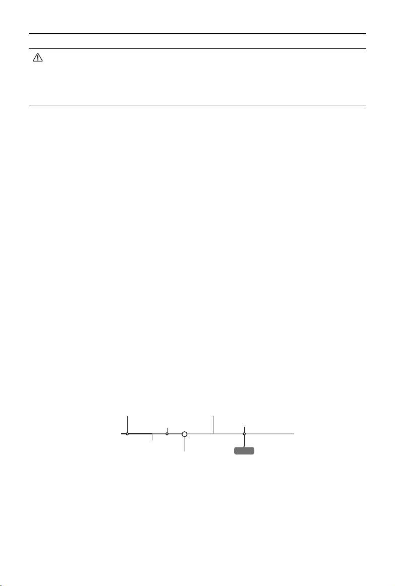
RTH Procedure
1. Home Point is recorded automatically.
* Make sure that the Landing Protection is enable in the DJI Pilot app.
©
2019 DJI All Rights Reserved.
23
MATRICE 200
SERIES V2 User Manual
2. RTH procedure is triggered i.e., Smart RTH, Low-Battery RTH, and Failsafe RTH.
3. Home Point is conrmed and the aircraft adjusts its orientation.
4. a. The aircraft will ascend to the pre-set RTH attitude and then y to the Home Point when the
aircraft is further than 20 m from the Home Point.
b. The aircraft will land automatically if RTH is triggered and the aircraft is less than 20 m from the
home point.
5. The aircraft will return to the Home Point, and Landing Protection* will be triggered to allow the
aircraft to land or hover in place. Refer to Landing Protection Function (p. 24) for details.
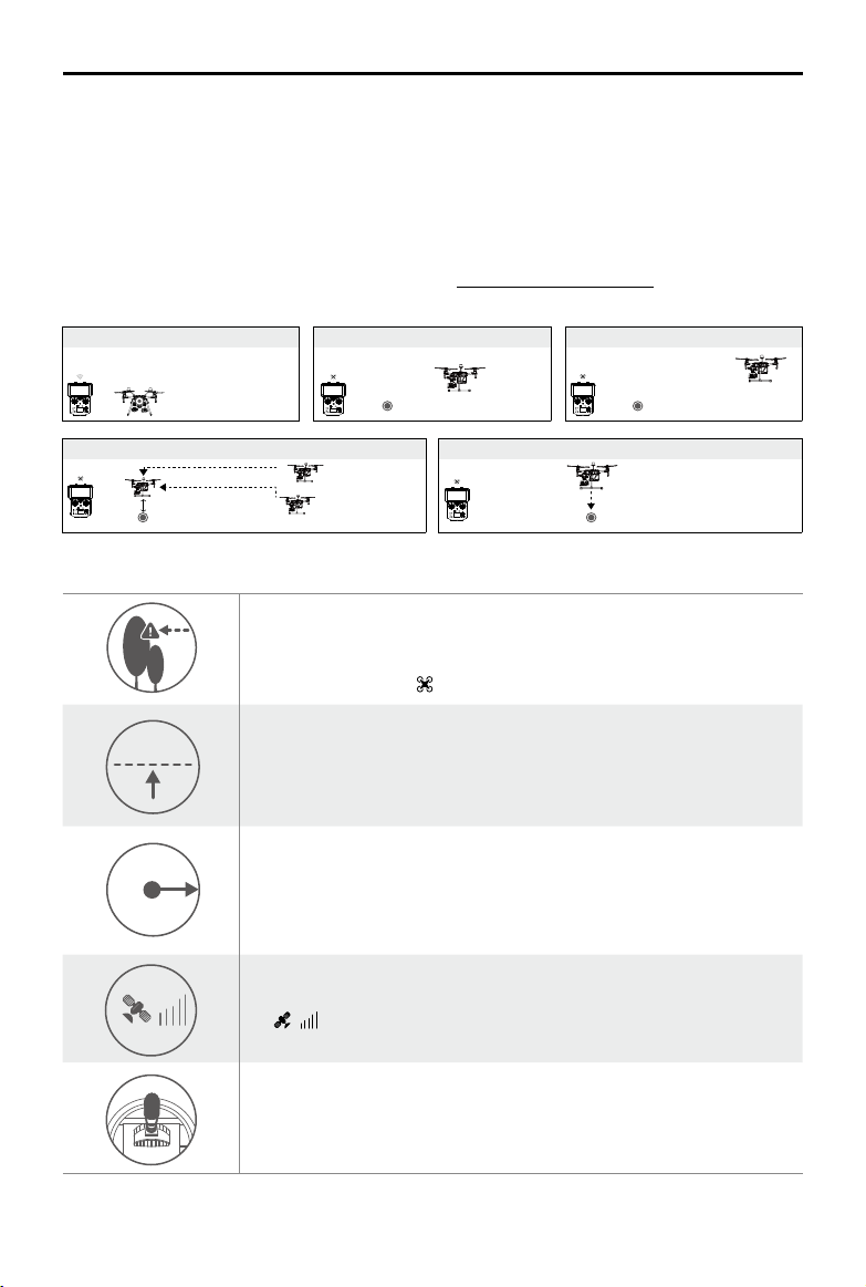
Use the Failsafe RTH for example:
Failsafe Safety Notices
The aircraft cannot avoid obstacles during Failsafe RTH when the
Forward Vision System is disabled. Therefore, it is important to set a
suitable Failsafe altitude before each flight. Launch the DJI Pilot app,
enter Camera and tap to set the Failsafe Altitude.
20 m
20 m
H
RTH Altitude
If the aircraft is ying under 65 feet (20 meters) and Failsafe (including
Smart RTH, Lower Battery RTH) is triggered, the aircraft will first
automatically ascend to 65 feet (20 meters) from the current altitude. You
can only cancel the ascending by exiting the Failsafe.
20 m
H
The aircraft automatically descends and lands if RTH is triggered when
the aircraft ies within a 65 foot (20 meter) radius of the Home Point. The
aircraft will stop ascending and immediately return to the Home Point if
you move the left stick when the aircraft is ying at an altitude of 65 feet (20
meters) or higher and Failsafe is triggered.
The aircraft cannot return to the Home Point when GPS signal is weak
( [
] displaying less than four bars) or is unavailable.
If you move the left stick when the aircraft is flying above 65 feet (20
meters) but below the pre-set Failsafe RTH altitude, the aircraft will stop
ascending and immediately return to the Home Point.
* Make sure that the Landing Protection is enable in the DJI Pilot app.
1. Record Home Point 2. Remote Control Signal Lost
5. Enter Landing Protection to land or hover
3. Signal Lost for Extended Time
4. RTH (Adjustable Altitude)
Height over HP<=Failsafe Altitude
Height over HP>Failsafe Altitude
Elevate to Failsafe Altitude
Failsafe Altitude
Hovering at 0.7 meters above the Home Point
Loading...