


GENETXTM
GUITAR
PROCESSOR
USER’S GUIDE
MANUAL DE INSTRUCCIONES
These symbols are internationally accepted symbols that warn of potential hazards with electrical products.The lightning flash means that there are dangerous voltages present within the unit.The exclamation point indicates that it is necessary for the user to refer to the owners manual.
These symbols warn that there are no user serviceable parts inside the unit. Do not open the unit. Do not attempt to service the unit yourself. Refer all servicing to qualified personnel. Opening the chassis for any reason will void the manufacturer’s warranty. Do not get the unit wet. If liquid is spilled on the unit, shut it off immediately and take it to a dealer for service.
Disconnect the unit during storms to prevent damage.
U.K. Mains Plug Warning
A molded mains plug that has been cut off from the cord is unsafe. Discard the mains plug at a suitable facility. Never under any circumstances should you insert a damaged or cut mains plug into a 13 amp power socket. Do not use the mains plug without the fuse cover in place. Replacement fuse covers can be obtained from your local retailer. Replacement fuses are 13 amps and MUST be ASTA approved to BS1362.
Safety Instructions
Notice for customers if your unit is equipped with a power cord.
Warning:This appliance must be earthed.
The cores in the mains lead are colored in accordance with the following code:
Green and Yellow - Earth Blue - Neutral Brown - Live
As colors of the cores in the mains lead of this appliance may not correspond with the colored markings identifying the terminals in your plug, proceed as follows:
•The core which is colored green and yellow must be connected to the terminal in the plug marked with the letter E, or with the earth symbol, or colored green, or green and yellow.
•The core which is colored blue must be connected to the terminal marked N, or colored black.
•The core which is colored brown must be connected to the terminal marked L, or colored red.
This equipment may require the use of a different line cord, attachment plug, or both, depending on the available power source at installation. If the attachment plug needs to be changed, refer servicing to qualified service personnel who should refer to the table below.The green/yellow wire shall be connected directly to the unit’s chassis.
CONDUCTOR |
WIRE COLOR |
||
|
|
Normal |
Alt |
L |
LIVE |
BROWN |
BLACK |
N |
NEUTRAL |
BLUE |
WHITE |
E |
EARTH GND |
GREEN/YEL |
GREEN |
Warning: If the ground plug is defeated, certain fault conditions in the unit or in the system to which it is connected can result in full line voltage between chassis and earth ground. Severe injury or death can then result if the chassis and earth ground are touched simultaneously.
Warning
For your protection, please read the following:
Water and Moisture: Appliances should not be used near water (e.g. near a bathtub, washbowl, kitchen sink, laundry tub, in a wet basement, or near a swimming pool, etc.) Care should be taken so that objects do not fall and liquids are not spilled into the enclosure through openings.
Power Sources: The appliance should be connected to a power supply only of the type described in the operating instructions or as marked on the appliance.
Grounding or Polarization: Precautions should be taken so that the grounding or polarization means of an appliance is not defeated.
Power Cord Protection: Power supply cords should be routed so that they are not likely to be walked on or pinched by items placed upon or against them, paying particular attention to cords at plugs, convenience receptacles, and the point where they exit from the appliance.
Servicing: To reduce the risk of fire or electrical shock, the user should not attempt to service the appliance beyond that described in the operating instructions. All other servicing should be referred to qualified service personnel.
For units equipped with externally accessible fuse receptacle: Replace fuse with same type and rating only.
Electromagnetic Compatibility
Operation is subject to the following conditions: •This device may not cause harmful interference.
•This device must accept any interference received, including interference that may cause undesired operation.
•Use only shielded interconnecting cables.
•Operation of this unit within significant electromagnetic fields should be av
Los simbolos de aqui arriba están reconocidos internacionalmente como de advertencia de los riesgos potenciales con aparatos eléctricos. El rayo dentro de un triángulo equilátero implica que dentro de la unidad existen voltajes peligrosos. El simbolo de exclamación dentro del triángulo equilátero indica que es necesario que lel usuario lea el manual de instrucciones de la unidad.
Estos simbolos también le adviertenque dentro de la unidad no hay ninguna pieza que pueda ser reparada por el propio usuario. No abrael aparato. Nunca intente hacer ningún tipo de reparación por sus propios medios. Consulte cualquier posible reparación únicamente a un Servico Técnico cualificado. La apertura del chasis por cualquier razón anulará la garantia del fabricante.
No permita que la unidad se humedezca. Si cae algún liquido en el aparato, apáguelo immediatemente y llévelo al distribuidor o servicio técnico. Desconecte la unidad durante las tormentas para evitar daños.
Aviso Sobre El Enchufe Para U.K.
El uso de un conector de otro cable no es seguro. Descarte este tipo de conexiones. BAJO NINGUNA CIRCUNSTANCIA DEBE INSERTAR
UN CABLE CORTADO O DAÑADO EN UN ENCHUFE DE CORRIENTE DE 13 AMP. No utilice un enchufe de corriente sin que etsé colocado la tapa del fusible. Puede conseguir recambios de estas tapas de fusible en su tienda local. Los fusibles de recambio son de 13 amps y DEBEN estar aprobados por la ASTA con el standard BS1362.
Instrucciones de seguridad
Aviso para los usuarios si su unidad esta equipada con un cable de alimentación. Precaucion: Esta unidad debe ser conectada a tierra.
Los filamentos del cable de alimentación están coloreados de acuerdo al sigiente código:
Verde y Amarillo - Tierra |
Azul - Neutral |
Marron - Activo |
Dado que los colores del cable de alimentación de esta unidad puede que
no se correspondan con las marcas de color identificativas de su enchufe, haga lo siguiente :
•El filamento que tiene color amarillo y verde debe ser conectado a la terminal del conector marcada con la letra E, o con el simbolo de tierra o de color verde o de color amarillo y verde.
•El filamento con color azul debe ser conectado a la terminal marcada con una N o de color negro.
•El filamento de color marrón debe ser conectado a la terminal marcada con una L o de color rojo.
Puede que para este aparato necesite usar un cable de alimentación o un conector distintos, dependiendo de la fuente de alimentación disponible en su instalación. Si debe cambiar el enchufe, contacte con un técnico cualificado y que este haga referencia a la tabla siguiente.
El filamento verde/amarillo debería ser conectado directamente a la carcasa de la unidad.
CONDUCTOR |
COLOR CABLE |
||
|
|
Normal |
Alt |
L |
Línea |
Marrón |
Negro |
N |
Neutral |
Azul |
Blanco |
E |
Tierra |
Verde/Amarillo |
Verde |
Precaución : Si se elimina la toma de tierra, determinadas condiciones
de avería de la unidad o del sistema al que esté conectada pueden hacer que haya cargas de voltaje de linea entre el chasis y la toma de tierra. Esto podriá producir daños graves o induso la muerte si tocase simultáneamente la carcasa y la toma de tierra.
Advertencia
AGUA Y HUMEDAD: No utilice este aparato demasiado cerca del agua (p.e. cerca de una piscina, fregadero, lavadora o en un sótano húmedo). Evite que pueda caer ningún objeto o líquidos dentro de la carcasa a tracés de las aberturas.
FUENTE DE ALIMENTACION: Este aparato debe ser conectado a una toma de alimentación solo del tipo descrito en este manual o marcado en la propria unidad.
TOMA DE TIERRA O POLARIZACION: Tome las precauciones necesarias para que la toma de tierra o polarización del aparato no queden anuladas.
PROTECCION DEL CABLE DE ALIMENTACION: Coloque los cables de alimentación de tal forma que no puedan ser pisados y que queden enganchados o aplastados por cosas colocadas sobre o contra ellos, con un cuidado especial en los receptáculos de entrada y conectores, y en el punto en el que los cables salen de las unidades.
REPARACIONES : Para reducir el riesgo de incendios o des cargas eléctricas, el usuario nunca debe tratar de hacer reparaciones en la unidad fuera de lo descrito en las instrucciones. Debe dirigir cualquier otra reparación al servicio técnico cualificado.
PARA LAS UNIDADES EQUIPADAS CON RECEPTACULO DE FUSIBLE ACCESIBLE DESDE EL EXTERIOR: Sustituya el fusible soo por otro del mismo tipo y características eléctricas.
Compatibilidad electromagnetica
Esta unidad cumple con las Especificaciones de producto indicada en la Declaración de Conformidad. Este hace que la unidad etsé sujeta a las dos condiciones siguientes:
•etsa unidad no puede producir interferencias molestas ni dañinas, y
•esta unidad debe recibir cualquier interferencia recibida, incluyendo las que puedan causar errores no deseado. Debe tratar de evitar el uso de esta unidad dentro decampos electromagnéticos significativos
•utilice solo cables de interconexión con blindaje.
I

DECLARATION OF CONFORMITY
Manufacturer’s Name: |
|
DigiTech |
Manufacturer’s Address: |
8760 S. Sandy Parkway |
|
|
|
Sandy, Utah 84070, USA |
declares that the product: |
|
|
Product name: |
GNX1 |
|
Note: Product name may be suffixed by the letters EX, EU, JA, and UK. |
||
Product option: |
all (requires Class II power adapter that conforms to the |
|
|
requirements of EN60065, EN60742, or equivalent.) |
|
conforms to the following Product Specifications: |
||
|
Safety: |
IEC60065 (1998) |
|
|
EN 60065 (1993) |
|
EMC: |
EN 55013 (1990) |
|
|
EN 55020 (1991) |
Supplementary Information:
The product herewith complies with the requirements of the Low Voltage Directive 72/23/EEC and the EMC Directive 89/336/EEC as amended by Directive 93/68/EEC.
DigiTech / Johnson
8760 S. Sandy Parkway
Sandy, Utah 84070, USA
Date: January 25, 2001
European Contact: Your local DigiTech / Johnson Sales and Service Office or
Harman Music Group
8760 South Sandy Parkway
Sandy, Utah
84070 USA
Ph: (801) 566-8800
Fax: (801) 568-7573
Warranty
All DigiTech products are manufactured with the highest care. The conditions of the warranty vary according the conventions that belong to every different country of distrbution. If you need any information related to the Waranty conditions in your own country, please contact your distributor or your retailer.
Digitech is a registered trademark.
NOTE: The information contained in this manual is subject to change at any time without notification. Some information contained in this manual may also be inaccurate due to undocumented changes in the product or operating system since this version of the manual was completed.The information contained in this version of the owner's manual supersedes all previous versions.
DECLARACION DE CONFORMIDAD
Nombre del fabricante: |
DigiTech |
Dirección del fabricante: |
8760 S. Sandy Parkway |
|
Sandy, Utah 84070, USA |
declara que el producto: |
|
Nombre del producto: GNX1
Nota: El nombre del producto puede ir precedido por las letras EX, EU, JA y UK.
Opciones del producto: |
todas (requiere un adaptador de corriente de clase |
|
II que cumpla con los requisitos de EN60065, |
|
EN60742 o equivalente). |
cumple con las siguientes especificaciones de producto:
Seguridad: |
IEC60065 (1998) |
|
EN 60065 (1993) |
EMC: |
EN 55013 (1990) |
|
EN 55020 (1991) |
Información complementaria:
El aparato citado anteriormente cumple con los requisitos de la Directiva de Bajo Voltaje 72/23/EEC y con la Directiva EMC 89/336/EEC tal como quedó enmendada por la Directiva 93/68/EEC.
DigiTech / Johnson 8760 S. Sandy Parkway Sandy, Utah 84070, USA
Fecha: 25 de enero de 2001
Contacto en Europa: Su distribuidor local DigiTech / Johnson y Servicio técnico o
Harman Music Group
8760 South Sandy Parkway
Sandy, Utah
84070 USA
Ph: (801) 566-8800
Fax: (801) 568-7573
Garantía
Todos los productos DigiTech son fabricados con el máximo cuidado. Las condiciones de la garantía varían de acuerdo a las convenciones y normas que correspondan en cada país de distribución.
Si necesita cualquier tipo de información relativa a las condiciones de Garantía en su país, contacte con su distribuidor o comercio local.
Digitech es una marca registrada.
NOTA: La información contenida en este manual está sujeta a cambios en cualquier momento sin previo aviso. Algunas de las informaciones contenidas en este manual puede que no sean precisas debido a cambios no notificados en el aparato o en el sistema operativo desde el momento de finalización de esta versión del manual.Toda la información contenida en esta versión del manual de instrucciones sustituye a la de las versiones anteriores.
II

Table of Contents |
|
Safety Information.................................................................... |
I |
Declaration of Conformity.................................................... |
II |
Warranty.................................................................................... |
II |
Section One - |
|
Introduction |
|
Congratulations........................................................................ |
1 |
Included Items .......................................................................... |
1 |
Quick Start .......................................................................... |
2 |
A Guided Tour of the GNX1................................................ |
3 |
The Front Panel .............................................................. |
3 |
The Rear Panel ................................................................ |
5 |
Getting Started ........................................................................ |
6 |
Making Connections................................................................ |
6 |
Mono .......................................................................... |
6 |
Stereo .......................................................................... |
6 |
Direct to a Mixing Console .......................................... |
7 |
Applying Power ........................................................................ |
7 |
About the GNX1 .................................................................... |
7 |
The Presets .......................................................................... |
7 |
Performance Mode.................................................................. |
8 |
Preset Mode...................................................................... |
8 |
FX Mode .......................................................................... |
8 |
The Footswitches .................................................................... |
9 |
The Expression Pedal.............................................................. |
9 |
Bypass Mode .......................................................................... |
9 |
Tuner Mode .......................................................................... |
9 |
Jam-A-Long .......................................................................... |
10 |
Learn-A-Lick Mode.................................................................. |
10 |
Using Learn-A-Lick.......................................................... |
10 |
Rhythm Trainer ........................................................................ |
11 |
Pattern .......................................................................... |
11 |
Tempo .......................................................................... |
11 |
Level .......................................................................... |
11 |
Section Two - Editing |
|
Functions |
|
Editing/Creating a Preset........................................................ |
12 |
Amp/Cabinet Modeling .......................................................... |
12 |
Editing Amp Models and Cabinet Types ............................ |
12 |
Selecting Amp/Cabinet Models .................................... |
13 |
Adjusting Amp Parameters............................................ |
13 |
Cabinet Tuning .................................................................. |
14 |
Creating HyperModels™ .............................................. |
14 |
Saving HyperModels™ (Amp Save) ............................ |
14 |
Editing the Effects .................................................................... |
16 |
Storing/Copying a Preset ...................................................... |
17 |
Section Three - Effects |
|
and Parameters |
|
About the Effects .................................................................... |
18 |
Effects Definitions.................................................................... |
18 |
Wah-Pickup ...................................................................... |
18 |
Compressor...................................................................... |
18 |
Whammy™/IPS................................................................ |
19 |
EQ .......................................................................... |
20 |
Noise Gate........................................................................ |
20 |
Chorus/Mod Effects ................................................................ |
21 |
Chorus...................................................................... |
21 |
Flanger ...................................................................... |
21 |
Phaser ...................................................................... |
21 |
Triggered Flanger.................................................... |
21 |
Triggered Phaser .................................................... |
22 |
Tremolo .................................................................... |
22 |
Panner ...................................................................... |
22 |
Vibrato ...................................................................... |
22 |
Rotary ...................................................................... |
22 |
AutoYa™.................................................................. |
23 |
YaYa™ ...................................................................... |
23 |
SynthTalk™.............................................................. |
23 |
Envelope Filter ........................................................ |
23 |
Detuner .................................................................... |
23 |
Pitch Shifting ............................................................ |
24 |
Delay .................................................................................. |
24 |
Reverb ................................................................................ |
24 |
Section Four - Tutorial |
|
A Guided Example .................................................................. |
25 |
Choose a Preset ...................................................................... |
25 |
Create a HyperModel™ ........................................................ |
25 |
Select the Green Channel Amp and Cabinet .......... |
25 |
Select the Red Channel Amp and Cabinet ................ |
25 |
Adjust the Green Channel Parameters...................... |
26 |
Adjust the Red Channel Parameters .......................... |
26 |
Tune the Cabinets .......................................................... |
26 |
Warp the Green and Red Channels Together.......... |
27 |
Save the HyperModel™ ................................................ |
27 |
Assign Models to the Preset Channels .............................. |
27 |
Edit the Preset.......................................................................... |
28 |
Select Pickup Type .................................................................. |
28 |
Turn the Compressor Off .................................................... |
28 |
Turn the Whammy™/IPS Off ................................................ |
28 |
Adjust the EQ .......................................................................... |
29 |
Adjust the Noise Gate .......................................................... |
29 |
Select and Adjust the Chorus .............................................. |
30 |
Turn the Delay Off .................................................................. |
30 |
Select and Adjust the Reverb................................................ |
30 |
Store the Preset ...................................................................... |
31 |
Section Five - Other |
|
Functions |
|
Expression Pedal ...................................................................... |
32 |
LFOs............................................................................................ |
32 |
Amp Footswitch ...................................................................... |
33 |
Expression Parameter Assignment List .............................. |
33 |
Utilities ...................................................................................... |
34 |
Mono/Stereo Output...................................................... |
34 |
Target System Setup ...................................................... |
34 |
Volume Pedal Update .................................................... |
35 |
V-Switch Threshold.......................................................... |
35 |
Expression Pedal Calibration ........................................ |
35 |
Bank Names...................................................................... |
36 |
MIDI Channel .................................................................. |
36 |
MIDI Bulk Dump.............................................................. |
36 |
MIDI Preset Dump.......................................................... |
36 |
User Amp Dump.............................................................. |
37 |
MIDI Mapping .................................................................. |
37 |
MIDI Merge ...................................................................... |
38 |
Factory Reset .................................................................. |
38 |
GENEDIT™ Editor/Librarian .................................................. |
38 |
Section Six - Appendix |
|
Preset List.................................................................................. |
39 |
MIDI CC List ............................................................................ |
40 |
MIDI Implementation.............................................................. |
41 |
Specifications ............................................................................ |
41 |
Indice |
|
Información de seguridad ...................................................... |
I |
Declaración de Conformidad .............................................. |
II |
Garantía...................................................................................... |
II |
Sección Uno - |
|
Introducción |
|
Felicidades .......................................................................... |
1 |
Elementos incluídos ................................................................ |
1 |
Arranque rápido ...................................................................... |
2 |
Recorrido guiado por el GNX1 .......................................... |
3 |
El panel frontal ................................................................ |
3 |
El panel trasero ................................................................ |
5 |
Puesta en marcha .................................................................... |
6 |
Conexiones .......................................................................... |
6 |
Mono .......................................................................... |
6 |
Stereo .......................................................................... |
6 |
Directo a una mesa de mezclas .................................. |
7 |
Encendido .......................................................................... |
7 |
Acerca del GNX1.................................................................... |
7 |
Los Presets .......................................................................... |
7 |
Modo de ejecución.................................................................. |
8 |
Modo Preset .................................................................... |
8 |
Modo FX .......................................................................... |
8 |
Los pedales de disparo .......................................................... |
9 |
El pedal de expresión ............................................................ |
9 |
Modo Bypass o de anulación ................................................ |
9 |
Modo de afinación .................................................................. |
9 |
Jam-A-Long .......................................................................... |
10 |
Modo Learn-A-Lick ................................................................ |
10 |
Uso del Learn-A-Lick...................................................... |
10 |
Entrenador rítmico.................................................................. |
11 |
Patrón .......................................................................... |
11 |
Tempo .......................................................................... |
11 |
Nivel .......................................................................... |
11 |
Sección Dos - Funciones |
|
de Edición |
|
Edición/creación de un Preset .............................................. |
12 |
Modelado de amplificador/recinto acústico ...................... |
12 |
Edición de modelos de amplificador y tipos de recinto...... |
12 |
Elección de modelos de amplificador/recinto .......... |
13 |
Ajuste de parámetros de amplificador ...................... |
13 |
Afinación de recinto ...................................................... |
14 |
Creación de HyperModels™ ...................................... |
14 |
Almacenamiento de HyperModels™ (Amp Save) .. |
14 |
Edición de los efectos ............................................................ |
16 |
Almacenamiento/Copia de un Preset ................................ |
17 |
Sección Tres - Efectos y |
|
Parámetros |
|
Acerca de los efectos ............................................................ |
18 |
Definiciones de los efectos .................................................. |
18 |
Wah-Pastilla ...................................................................... |
18 |
Compresor........................................................................ |
18 |
Whammy™/IPS................................................................ |
19 |
EQ .......................................................................... |
20 |
Puerta de ruidos .............................................................. |
20 |
Chorus/Efectos de modulación ............................................ |
21 |
Chorus...................................................................... |
21 |
Flanger ...................................................................... |
21 |
Modulador de fase ................................................ |
21 |
Flanger con disparo .............................................. |
21 |
Mod. de fase con disparo .................................... |
22 |
Tremolo .................................................................... |
22 |
Panorama ................................................................ |
22 |
Vibrato ...................................................................... |
22 |
Altavoz giratorio .................................................... |
22 |
AutoYa™.................................................................. |
23 |
YaYa™ ...................................................................... |
23 |
SynthTalk™.............................................................. |
23 |
Envolvente de filtro................................................ |
23 |
Desafinador ............................................................ |
23 |
Cambio de tono .................................................... |
24 |
Retardo .............................................................................. |
24 |
Reverb ................................................................................ |
24 |
Sección Cuatro - Tutorial
Un ejemplo guiado .................................................................. |
25 |
Escoja un Preset ...................................................................... |
25 |
Creación de un HyperModel™ .......................................... |
25 |
Elija el amplificador y recinto del canal verde .......... |
25 |
Elija el amplificador y recinto del canal rojo ............ |
25 |
Ajuste los parámetros del canal verde ...................... |
26 |
Ajuste los parámetros del canal rojo.......................... |
26 |
Afinación de los recinto ................................................ |
26 |
Unión de los canales verde y rojo .............................. |
27 |
Almacenamiento del HyperModel™ .......................... |
27 |
Asignación de modelos a los canales Preset .................... |
27 |
Edición del Preset .................................................................... |
28 |
Elección del tipo de pastilla .................................................. |
28 |
Desactivación del compresor .............................................. |
28 |
Desactivación del Whammy™/IPS ...................................... |
28 |
Ajuste del EQ .......................................................................... |
29 |
Ajuste de la puerta de ruidos .............................................. |
29 |
Elección y ajuste del Chorus .............................................. |
30 |
Desactivación del retardo...................................................... |
30 |
Selección y ajuste de la Reverb ............................................ |
30 |
Almacenamiento del preset .................................................. |
31 |
Sección Cinco - Otras |
|
Funciones |
|
Pedal de expresión .................................................................. |
32 |
LFOs............................................................................................ |
32 |
Pedal de disparo de amplificador ........................................ |
33 |
Listado de asignación de parámetros de expresión ........ |
33 |
Utilidades .................................................................................. |
34 |
Salida Mono/Stereo ........................................................ |
34 |
Configuración del sistema de destino ........................ |
34 |
Actualización del pedal de volumen............................ |
35 |
Umbral del V-Switch........................................................ |
35 |
Calibración del pedal de expresión ............................ |
35 |
Nombres de bancos........................................................ |
36 |
Canal MIDI ........................................................................ |
36 |
Volcado de datos MIDI .................................................. |
36 |
Volcado de preset MIDI ................................................ |
36 |
Volcado de amplificadores de usuario ........................ |
37 |
Mapa o distribución MIDI.............................................. |
37 |
Mezcla MIDI...................................................................... |
38 |
Reinicialización a valores de fábrica ............................ |
38 |
Editor/biblioteca GENEDIT™ ................................................ |
38 |
Sección Seis - Apéndices |
|
Listado de presets .................................................................. |
39 |
Listado de CC MIDI ................................................................ |
40 |
Tabla de implementación MIDI ............................................ |
41 |
Especificaciones técnicas ........................................................ |
41 |

SECTION UN - INTRODUCTION
Section One - Introduction
Congratulations on purchasing the DigiTech GNX1, the most advanced guitar processor of its kind.There has never been a guitar system as unlimited as the GNX1.Thanks to the highly advanced technology provided by GeNetX™ and the extreme horsepower contained in the Audio DNA™ DSP engine, you now have the capability to literally create the tone of your own guitar amplifier and speaker cabinet. All of this power enables you to create a sound that is as unique as your music. In addition to designing your own amp and speaker cabinet, the GNX1 provides the sound coloring tools only a library full of studio quality effects could produce.
The intuitive user interface makes programming as simple as turning a knob. However, when you have to stop playing because your fingers are bleeding, we feel that your recovery time would be well spent by reading through this User’s Guide with your GNX1 in front of you. It could assist you in improving on the seemingly perfect tone you may have already created.
Included Items
Before you tear open the packaging and toss the manual over your shoulder, please check to make sure the following items have been included:
•GNX1
•PS0913B Power Supply
•Warranty Card
•User’s Guide
The utmost care was taken in manufacturing and packaging your GNX1. Everything should be included and in perfect working condition. However, if you find that anything is missing, contact the factory at once. Please take a moment to fill out the Warranty Card. It is your safeguard in the unlikely event that the GNX1 develops a problem.
SECCIÓN UNO - INTRODUCCIÓN
Sección Uno - Introducción
Felicidades por comprar el DigiTech GNX1, el procesador de guitarra más avanzado de su clase. Nunca ha existido un sistema de guitarra tan ilimitado como el GNX1. Gracias a la avanzada tecnología ofrecida por GeNetX™ y al gigantesco poder que alberga la unidad DSP Audio DNA™, ahora tiene la capacidad de crear literalmente el sonido de su propio amplificador de guitarra y recinto acústico. Todo este potencial le permite crear un sonido que sea tan único y personal como su música. Además del diseño de su propio amplificador y recinto acústico, el GNX1 le ofrece la amplia gama de herramientas de coloración del sonido que solo puede producir una completa biblioteca de efectos con calidad de estudio.
El fácil e intuitivo interface de usuario hace que la programación sea tan simple como girar un mando. No obstante, cuando ya tenga los dedos despellejados de tanto tocar y deba detenerse un rato, pensamos que sería un buen momento para dedicar unos minutos a leer completamente este manual de instrucciones con su GNX1 delante. Puede ayudarle a mejorar ese sonido ya casi perfecto que ha conseguido crear.
Elementos incluídos
Antes de despedazar la caja y tirar este manual a un rincón, asegúrese de que hayan sido incluídos los siguientes elementos:
•GNX1
•Fuente de alimentación PS0913B
•Tarjeta de garantía
•Manual de instrucciones
Hemos puesto el máximo cuidado en la fabricación y embalaje de su GNX1.Todos los elementos deberían estar dentro de la caja y en perfecto estado operativo. No obstante, si falta alguno de ellos, póngase en contacto con nosotros inmediatamente. Aproveche también un momento para rellenar la Tarjeta de Garantía. Ella será su salvavidas para el improbable caso de que se encuentre con problemas con su GNX1.
 1
1

SECTION UN - INTRODUCTION
Quick Start
This Quick Start guide is included for those of you who would rather begin creating now and read about the depths of the GNX1 gene pool later.
Making Connections:
Connect your instrument to the Input jack on the rear panel. Connect the Left /Right Outputs to the input(s) of your amplifier(s), power amp, or mixer.
Apply Power:
Turn the Output Knob on the rear panel of the GNX1 all the way down (fully counter clockwise). Connect the plug of the PS0913B power supply to the Power jack on the GNX1. Connect the other end of the PS0913B power supply to an AC outlet and turn the GNX1 Power Switch to the on position.Turn the power of your amplifier(s) to the on position and adjust the volume(s)to a normal playing level. Gradually increase the GNX1 Output Knob to achieve the desired volume.
Select Output Mode:
To select the output mode, press the Utility button once and use the Data Up /Down buttons to select either Stereo or Mono output mode.
Select Target System Setup:
The GNX1 needs to know the type of amplification system it will be used with. From the previous Output selection step, press the Rhythm button once.This will take you to the Target System Setup menu. Use the Data Up/Down buttons to select the amplification system you will be using the GNX1 with.Then press the Exit button to return the GNX1 to Performance mode.
Select Preset:
The GNX1 comes with 48 pre-programmed Factory Presets, and 48 User Presets. From the factory, the User Presets are exact duplicates of the Factory Presets.This allows you to experiment without running the risk of losing any of the original sounds contained in the GNX1.
Use the Bank Footswitch (9) to Select a Bank and the 1-3 Footswitches (1) to select different Presets.The Data Up/Down buttons (7) can also be used to select a Preset. Once you have found Presets that suit your taste, you can alter the sounds to your specific needs.Turning the Knobs (5) below the Display will select Amp and Cabinet Models for the Green and Red Amp Channels.The Middle Knob will Warp the two channels together. Pressing the Status button (4) will provide access to the Gain, EQ, and Level Parameters for the Green and Red Channels.The Effects contained in each Preset can be edited also. Press the Effect Select Up/Down buttons (3) to access and edit any of the effects.The Matrix LEDs will light indicating which Effect has been selected. Follow the row with the lighted LED across to determine which column the Parameter needing adjustment is located. Once a parameter has been selected, you may increase or decrease the parameter value to your liking by rotating the Knob located directly above the column for the desired parameter. Remember that you are not at risk of losing any of the sounds the GNX1 came with so, don’t be afraid to experiment.
SECCIÓN UNO - INTRODUCCIÓN
Arranque rápido
Hemos incluído esta guía de arranque rápido para aquellos que prefieran empezar a crear primero y profundizar en las maravillas del GNX1 después.
Conexiones:
Conecte su instrumento en la toma Input del panel trasero. Conecte las Salidas izquierda/derecha a la entrada(s) de su amplificador(s), etapa de potencia o mesa de mezclas.
Encendido:
Gire completamente a la izquierda el mando de salida del panel trasero del GNX1 para bajarlo al mínimo. Conecte la toma de la fuente de alimentación PS0913B a la entrada Power del GNX1. Conecte el otro extremo a una salida de corriente alterna y coloque el interruptor Power del GNX1 en la posición on. Encienda su amplificador(s) y ajuste su volumen a un nivel de ejecución normal. Vaya girando lentamente hacia la derecha el mando de salida del GNX1 hasta conseguir el volumen que quiera.
Selección del modo de salida:
Para elegir el modo de salida, pulse una vez el botón Utility y use los botones Data arriba/abajo para elegir el modo de salida Stereo o Mono.
Elección de la configuración del sistema de destino:
El GNX1 necesita saber el tipo de sistema de amplificación con el que lo va a usar. Desde el paso anterior de elección de salida, pulse una vez el botón Rhythm. Esto hará que vaya al menú de configuración de sistema de destino. Use los botones Data arriba/abajo para elegir el sistema de amplificación con el que usará el GNX1. Pulse después el botón Exit para hacer que el GNX1 vuelva al modo de ejecución normal.
Selección de Preset:
El GNX1 viene con 48 Presets pre-programados en fábrica y 48 Presets de usuario. Cuando sale de fábrica, los presets de usuario son réplicas exactas de los presets de fábrica. Esto le permite experimentar sin correr el riesgo de perder ninguno de los originales sonidos con los que viene el GNX1.
Use el Pedal de disparo Bank (9) para elegir un Banco y los Pedales de disparo 1-3 (1) para elegir entre los distintos Presets.También puede usar los botones Data arriba/abajo (7) para elegir los Presets. Una vez que haya localizado los Presets que se adapten a su gusto, puede modificar sus sonidos para adaptarlos a sus necesidades específicas. El giro de los mandos (5) que están debajo de la pantalla elegirán los modelos de amplificador y recinto para los canales de amplificador verde y rojo. El mando central unirá juntos los dos canales. El pulsar el botón Status (4) le dará acceso a los parámetros de ganancia, ecualizador y nivel para los canales verde y rojo.También puede editar los efectos que están contenidos en cada Preset. Pulse los botones Effect Select arriba/abajo (3) para poder acceder y editar cada uno de los efectos. Los LEDs de la Matriz se iluminarán para indicarle cual de los efectos ha sido elegido. Siga la fila cuyo piloto esté iluminado para determinar en qué columna está el parámetro que quiera ajustar. Una vez que haya elegido un parámetro, puede aumentar o disminuir el valor del mismo a su gusto con solo girar el Mando giratorio que esté situado justo encima de la columna del parámetro deseado. Recuerde que no corre el riesgo de perder ninguno de los sonidos con los que vino el GNX1 por lo que, no tenga ningún miedo en experimentar.
2 
SECTION UN - INTRODUCTION |
|
|
|
|
|
SECCIÓN UNO - INTRODUCCIÓN |
|||||||||||||||||||||
A Guided Tour of the GNX1 |
|
|
|
|
|
Recorrido guiado por el GNX1 |
|||||||||||||||||||||
The Front Panel |
|
|
|
|
|
El panel frontal |
|||||||||||||||||||||
|
|
|
|
|
|
|
|
|
|
|
|
|
|
|
|
|
|
|
|
|
|
|
|
|
|
|
|
|
|
|
|
|
|
|
|
|
|
|
|
|
|
|
|
|
|
|
|
|
|
|
|
|
|
|
|
|
|
|
|
|
|
|
|
|
|
|
|
|
|
|
|
|
|
|
|
|
|
|
|
|
|
|
|
|
|
|
|
|
|
|
|
|
|
|
|
|
|
|
|
|
|
|
|
|
|
|
|
|
|
|
|
|
|
|
|
|
|
|
|
|
|
|
|
|
|
|
|
|
|
|
|
|
|
|
|
|
|
|
|
|
|
|
|
|
|
|
|
|
|
|
|
|
|
|
|
|
|
|
|
|
|
|
|
|
|
|
|
|
|
|
|
|
|
|
|
|
|
|
|
|
|
|
|
|
|
|
|
|
|
|
|
|
|
|
|
|
|
|
|
|
|
|
|
|
|
|
|
|
|
|
|
|
|
|
|
|
|
|
|
|
|
|
|
|
|
|
|
|
|
|
|
|
|
|
|
|
|
|
|
|
|
|
|
|
|
|
|
|
|
|
|
|
|
|
|
|
|
|
|
|
|
|
|
|
|
|
|
|
|
|
|
|
|
|
|
|
|
|
|
|
|
|
|
|
|
|
|
|
|
|
|
|
|
|
|
|
|
|
|
|
|
|
|
|
|
|
|
|
|
|
|
|
|
|
|
|
|
|
|
|
|
|
|
|
|
|
|
|
|
|
|
|
|
|
|
|
|
|
|
|
|
|
|
|
|
|
|
|
|
|
|
|
|
|
|
|
|
|
|
|
|
|
|
|
|
|
|
|
|
|
|
|
|
|
|
|
|
|
|
|
|
|
|
|
|
|
|
|
|
|
|
|
|
|
|
|
|
|
|
|
|
|
|
|
|
|
|
|
|
|
|
|
|
|
|
|
|
|
|
|
|
|
|
|
|
|
|
|
|
|
|
|
|
|
|
|
|
|
|
|
|
|
|
|
|
|
|
|
|
|
|
|
|
|
|
|
|
|
|
|
|
|
|
|
|
|
|
|
|
|
|
|
|
|
|
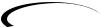
1.1-3 Footswitches - Depending on the currently selected mode, these 3 footswitches are used to select Presets, access the Tuner, turn individual effects on and off, change Amp Channels, select functions in Learn-A-Lick mode, or bypass the GNX1.
2.Matrix - The Matrix LEDs provide a visual indication of active effects for the currently selected Preset in performance mode, or the currently selected effect row in edit mode.
3.Effect Select Buttons - The Effect Select buttons are used in conjunction with the Matrix LEDs to choose the row of effects you wish to edit.
4.Status Button - In Performance mode, the Status button is used to select the Green or Red Amp Channel.The Status button is also used to enable the Amp and Cabinet Warping feature (indicated by a yellow LED next to the Status button). In Edit mode it is used to change the on/off status of the selected effect, select the Green or Red Channel for EQ edits, or select a controller type for Expression Assignment.
5.Parameter Knobs - In performance mode, these 5 knobs are used to select Amp Models, Speaker Cabinets, and Warp the Models. In Green or Red mode, they adjust the Amp Gain, EQ and Level for the Green and Red Amp Channels. In Edit mode, they are used to adjust the Parameters listed in the column directly below each knob for the currently selected row of Effects.
6.Display - The Display consists of six alpha-numeric green characters, and two red numeric digits.The Display provides information for several different functions depending on the mode that has been selected. In Performance mode, the Display will show the currently selected Preset name and number. The Display will also show Bank names when changing banks, and momentarily flash the active Amp Channel when the Amp Channel is switched. In Edit mode, the alpha-numeric Display will show the currently selected Effect Parameter and value or status of the Parameter. In Tuner mode, the numeric Display will show the note played and provide sharp or flat indications. In Learn-A-Lick mode, the alpha-numeric display shows the currently selected function and the numeric Display provides an elapsed time for record and playback.
1.1-3 Pedales de disparo - Dependiendo del modo activo, estos 3 pedales de disparo se usan para elegir Presets, acceder al afinador, activar o desactivar efectos individuales, cambiar canales de amplificador, elegir funciones en el modo Learn-A-Lick o anular el GNX1.
2.Matriz - La Matriz de LEDs le ofrece una indicación visual de los efectos activos en el preset elegido en ese momento en el modo de ejecución, o de la fila del efecto activo en el modo de edición.
3.Botones selectores de efectos - Estos botones selectores de efectos se usan junto con la matriz de LEDs para escoger las filas de efectos que quiera editar.
4.Botón Status - En el modo de ejecución, este botón se usa para elegir el canal de amplificación verde o rojo. Este botón también se usa para activar la función de deformación de amplifidor y recinto (indicada por un piloto amarillo al lado de este botón). En el modo de edición, este botón se usa para cambiar el estado on/off del efecto elegido, elegir el canal verde o rojo para las ediciones EQ o elegir un tipo de controlador para la asignación de expresión.
5.Mandos Parameter - En el modo de ejecución, estos 5 mandos se usan para elegir los modelos de amplificador, recintos acústicos y deformar los modelos. En el modo verde o rojo, ajustan la ganancia de amplificación, EQ y nivel para los canales de amplificador verde o rojo. En el modo de edición se usan para ajustar los parámetros relacionados en la columna que está justo debajo de cada uno de los mandos para la fila de efectos activa.
6.Pantalla - La pantalla consta de seis caracteres verdes alfanuméricos, y dos dígitos numéricos rojos. Le ofrece información de diversas funciones dependiendo del modo elegido. En el modo de Ejecución, la pantalla le mostrará el preset elegido activo, con nombre y número.También le mostrará los nombres de los bancos cuando esté cambiando de uno a otro, y en ella parpadeará momentáneamente el canal de amplificador activo cuando lo active. En el modo de Edición la pantalla alfanumérica le mostrará el parámetro de efecto elegido en ese momento y su valor o estado del parámetro. En el modo de Afinador, la pantalla numérica le mostrará la nota tocada, así como indicaciones de bemol o sostenido. En el modo Learn-A-Lick, la pantalla alfanumérica le muestra la función activa mientras que la pantalla numérica le indica el tiempo transcurrido de grabación y reproducción.
 3
3

SECTION ONE - INTRODUCTION
7.Data Up/Down Buttons - These buttons are used to increase and decrease the currently selected Preset in Performance mode, value of currently displayed parameter in edit mode, the value or status of the currently selected Utility or Rhythm function, or the alpha-numeric character in the naming procedure.
8.Mode Buttons - These 6 buttons are used to select various modes in which the GNX1 will function.The Exit button performs a single function while the other 5 buttons perform dual functions based upon the current operation of the GNX1.The buttons are labeled as follows:
A)FX Mode - The FX Mode button selects whether the 1-3 footswitches will recall Presets within the selected Bank, or act as on/off switches for the individual effects in the currently selected Preset.The FX Mode button will light when the switches are performing effects on/off functions.The function of this button changes to select the previous character when naming a Preset, or select the previous menu in Utility mode.
B)Exit - This button acts as a panic button and is used to escape from any mode or level of editing returning the GNX1 to Performance mode.
C)Rhythm - The Rhythm button is used to access the Rhythm Trainer drum loop feature in the GNX1.When the Rhythm feature is selected, the LED will light, the drum loop begins playing, and the bottom row of Mode buttons can be used in conjunction with the Data Up and Down buttons to select and edit the Pattern,Tempo, and Level.The function of this button changes to select the next character when naming a Preset, or select the next menu in Utility mode.
D)Store - The Store button is used to save your custom edits to the user Presets.The function of this button changes to select Pattern in Rhythm mode.
E)Utility - The Utility button provides access to several global functions including Output Mode,Target System Setup,Volume Pedal Update,V- Switch, Pedal Calibration, Bank Names, MIDI Channel, Sysex Dumps, MIDI Mapping, MIDI Merge, and Factory Reset menus.The function of this button changes to select Tempo in Rhythm mode.
F)Amp Save - This button is used to store any changes made to the characteristics of Amps and Cabinets (tone, gain, level, amp type, cabinet type, warp, or cabinet tuning) as HyperModels™ for later retrieval or warping.The function of this button changes to select Level in Rhythm mode.
9.Bank/Preset Footswitch - The function of this switch will change depending upon whether the FX Mode is active or inactive.When FX Mode is active, this switch is used to change Presets. Successive presses of this switch will advance through all User Presets (indicated by a green LED), and Factory Presets (indicated by a red LED). Pressing and holding this switch will descend backwards through all User and Factory Presets.When FX Mode is inactive, successive presses of this switch will advance through all User (indicated by a green LED) and Factory (indicated by a red LED) Banks. Pressing and holding this switch will descend backwards through all User and Factory Banks.
10.Expression Pedal - The Expression Pedal controls the assigned Effect Parameter in real time. Most Parameters within the GNX1 are available for Expression Pedal assignment. Applying extra pressure to the toe of the Expression Pedal will switch between controlling the assigned Parameter and turning the Wah on and off.
SECCIÓN UNO - INTRODUCCIÓN
7.Botones Data Arriba/Abajo - Estos botones se usan para aumentar y disminuir el preset activo en ese momento en el modo de ejecución, el valor del parámetro visualizado en ese momento en el modo de edición, el valor o estado de la función de utilidades o rítmica activa entonces, o el caracter alfanumérico en el proceso de nombrado.
8.Botones Mod -Estos 6 buttons se usan para elegir los diversos modos en los que funcionará el GNX1. El botón Exit realiza una función única mientras que los otros 5 botones tienen funciones dobles dependiendo de la operación activa del GNX1. Los botones están indicados de la siguiente forma:
A)FX Mode - Este botón elige si los pedales de disparo 1-3 cargarán
Presets dentro del banco elegido, o actuarán como interruptores on/off para los efectos individuales en el preset activo. El botón FX Mode se iluminará cuando los interruptores estén actuando como on/off de efectos. Este botón elige el carácter anterior durante el proceso de nombrado de un preset, o elige el menú anterior en el modo de utilidades.
B)Exit - Este botón actúa como un botón de pánico y se usa para salir de cualquier modo o nivel de edición, devolviendo el GNX1 al modo de ejecución normal.
C)Rhythm - El botón Rhythm se usa para acceder a la función de bucle de batería del Entrenador rítmico del GNX1. Cando se elige esta función, el piloto se enciende, el bucle de batería comienza a reproducirse y puede usar la fila inferior de botones de modo junto con los botones Data arriba y abajo para elegir y editar el patrón, tempo y nivel. Este botón pasa a elegir el siguiente carácter en los procesos de nombrado de un preset, o elige el siguiente menú en el modo de utilidades.
D)Store - Este botón se usa para almacenar sus ediciones personales en los presets de usuario. La función de este botón cambia para elegir los patrones en el modo rítmico.
E)Utility - Este botón le permite acceder a diversas funciones globales como las de modo de salida, configuración de sistema de destino, actualización de pedal de volumen,V-Switch, calibración de pedal, nombres de banco, canal MIDI, volcados Sysex, mapa MIDI, mezcla MIDI y reinicialización a valores de fábrica. Este botón se ocupa de elegir el tempo en el modo rítmico.
F)Amp Save - Este botón se usa para almacenar cualquier cambio que haga en las características de los amplificadores y recintos (sonido, ganancia, nivel, tipo de amplificador, tipo de recinto, deformación o afinación de recinto) como HyperModels™ para su recuperación o deformación posteriores. Este botón se ocupa de elegir el nivel en el modo rítmico.
9.Pedal Bank/Preset - La función de este interruptor cambiará dependiendo de si el modo FX está activo o no. Cuando el modo FX está activo, este interruptor se usa para cambiar los presets. Las pulsaciones sucesivas de este interruptor harán que vaya avanzando a través de todos los presets de usuario (indicados por un LED verde), y los presets de fábrica (indicados por un LED rojo). El mantener pulsado este interruptor hará que vaya pasando hacia atrás por todos los presets. Cuando el modo FX no esté activo, las pulsaciones sucesivas de este interruptor harán que vaya pasando por todos los bancos de usuario (indicados por un piloto verde) y de fábrica (piloto rojo). El mantener pulsado este interruptor hará que vaya desplazándose hacia atrás por los bancos.
10.Pedal de expresión - El pedal de expresión controla el parámetro de efecto asignado en tiempo real. En el GNX1 puede asignar la mayoría de los parámetros al pedal de expresión. El aplicar una presión extra en la puntera de este pedal hará que cambie entre el control del parámetro asignado y la activación on/off del Wah.
4 
SECTION ONE - INTRODUCTION |
|
|
SECCIÓN UNO - INTRODUCCIÓN |
|||||||||||||||
Rear Panel |
|
|
Panel trasero |
|||||||||||||||
|
|
|
|
|
|
|
|
|
|
|
|
|
|
|
|
|
|
|
|
|
|
|
|
|
|
|
|
|
|
|
|
|
|
|
|
|
|
|
|
|
|
|
|
|
|
|
|
|
|
|
|
|
|
|
|
|
|
|
|
|
|
|
|
|
|
|
|
|
|
|
|
|
|
|
|
|
|
|
|
|
|
|
|
|
|
|
|
|
|
|
|
|
|
|
|
|
|
|
|
|
|
|
|
|
|
|
|
|
|
|
|
|
|
|
|
|
|
|
|
|
|
|
|
|
|
|
|
|
|
|
|
|
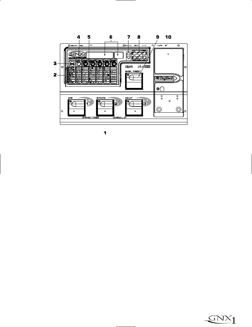
1.Input Jack - Connect your instrument to this jack.
2.Jam-A-Long Jack - Use an 1/8” stereo plug to connect this jack to the output of a tape or CD player.This allows you to jam along with the music, or to record a musical passage into the Learn-A-Lick phrase recorder.
3.Headphone Output - Connect stereo headphones to this jack. Be sure to set the Target System Setup mode to Direct when listening through Headphones (see page 34 for more information on selecting the Target System Setup). Do not connect a mono plug to this jack as doing so may damage the output driver.
4.Left Output - Connect from this jack to the input of an amplifier, input of a power amp, or line input of a mixing console.
5.Right Output - Use this jack in conjunction with the Left Output for stereo applications. Connect from this output to the input of a second amplifier, or the right input of a stereo power amp.
6.Output Level - This knob controls the overall volume level of the GNX1.
7.Power Switch - Turns the power to the GNX1 on and off.
8.Power Input - Connect only the provided DigiTech PS0913B power supply to this jack.
9.MIDI In - This jack is used to receive all incoming MIDI data intended to control the GNX1. Connect from this jack to the MIDI out of a computer, sequencer, MIDI controller, or MIDI storage device.
10.MIDI Out/Thru - This jack is used for all MIDI data being sent out of the GNX1. Connect from this jack to the MIDI in of a computer, or external MIDI recording device.When enabled, the MIDI Thru function of this jack sends out the same information that is received at the MIDI In of the GNX1.
11.Strain Relief - This is used to secure the power cord and prevent possible disconnects during performance.
1. Clavija de entrada - Conecte su instrumento a esta entrada.
2.Toma Jam-A-Long - Use un conector stereo de 3,5 mm para conectar esta toma con la salida de su pletina o reproductor CD. Esto le permite improvisar junto con la música, o grabar un pasaje musical en la grabadora de frases musicales Learn-A-Lick.
3.Salida de auriculares - Conecte unos auriculares stereo a esta salida. Asegúrese de ajustar el modo de configuración de sistema de destino a Direct cuando use los auriculares (vea en la página 34 más información acerca de esto). No conecte una clavija mono a esta salida ya que eso podría dañar el cabezal de salida.
4.Salida izquierda -Conecte esta salida a la entrada de un amplificador, la entrada de una etapa de potencia, o la entrada de línea de una mesa de mezclas.
5.Salida derecha - Use esta salida junto con la salida izquierda para aplicaciones stereo. Conecte esta salida a la entrada de un segundo amplificador, o a la entrada derecha de una etapa de potencia stereo.
6.Nivel de salida - Este mando controla el nivel de volumen global del GNX1.
7.Interruptor Power - Enciende o apaga el GNX1.
8.Entrada Power Conecte a esta toma solo la fuente de alimentación DigiTech PS0913B.
9.MIDI In - Este conector se usa para recibir todos los datos MIDI entrantes con los que quiera controlar el GNX1. Conecte esta entrada a la toma MIDI out de un ordenador, secuenciador, controlador MIDI o unidad de almacenamiento MIDI.
10.MIDI Out/Thru - Este conector se usa para todos los datos MIDI que sean emitidos desde el GNX1. Conecte esta clavija a la toma MIDI in de un ordenador o unidad de grabación MIDI exterior. Cuando esté activa, la función MIDI Thru de esta clavija emitirá la misma información que sea recibida en la toma MIDI In del GNX1.
11.Clavija anti-tirones - Se usa para fijar el cable de alimentación y evitar posibles desconexiones accidentales durante la ejecución.
 5
5
SECTION ONE - INTRODUCTION
Getting Started
Making Connections
Before connecting the GNX1, make sure that the power to your amplifier is turned off, and that the power switch on the rear panel of the GNX1 is in the off position.
There are several different connection options available when using the GNX1. You may run mono into an amp or power amp, stereo into two amps or a stereo power amp, direct into a mixing console, or a combination of these.The following diagrams show the connections for some of these options.
NOTE: The type of amplification system the GNX1 will be used in should be selected in the Target System Setup of the Utility menu. See page 34 for
more information on selecting the Target System Setup.
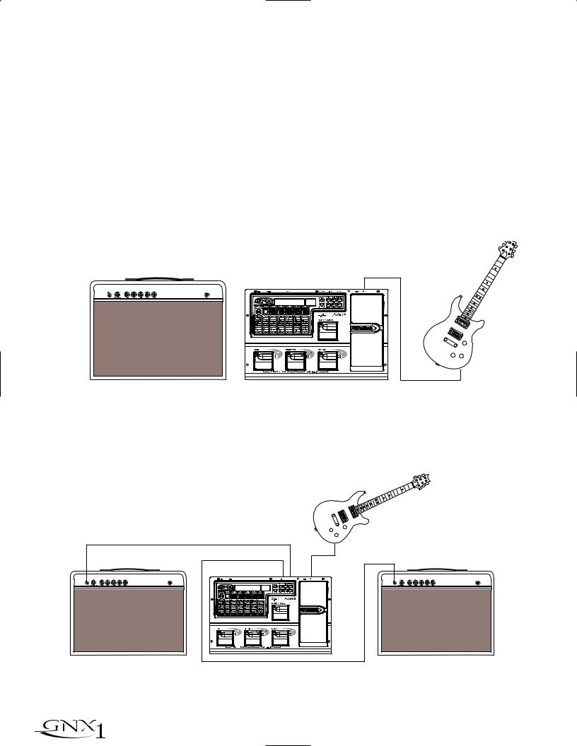
Mono Operation
Connect your guitar to the input of the GNX1. Connect the Left output of the GNX1 to the instrument input on your amplifier, or to the line input of a power amp. Select Mono as the Output mode in the Utility menu. See page 34 for more on selecting the Output mode.
SECCIÓN Uno - INTRODUCCIÓN
Puesta en marcha
Conexiones
Antes de conectar el GNX1, asegúrese que su amplificador esté apagado y que el interruptor de encendido del panel trasero del GNX1 esté en la posición off.
Cuando use el GNX1 dispone de varias opciones de conexión posibles entre las que elegir. Puede hacer una conexión en mono a un amplificador o etapa de potencia, en stereo a dos amplificadores o una etapa de potencia stereo, directo a una mesa de mezclas o usar una combinación de estas conexiones. Los diagramas siguientes le muestran las conexiones para algunas de esas opciones.
NOTA: El tipo de sistema de amplificación con el que será usado el GNX1 debe ser elegido en la Configuración de sistema de destino del menú de
utilidades.Vea la página 34 para más información acerca de estos ajustes.
Funcionamiento Mono
Conecte su guitarra a la entrada del GNX1. Conecte la salida izquierda del GNX1 a la entrada de instrumento de su amplificador o a la entrada de línea de una etapa de potencia. Elija Mono como modo de salida en el menú de utilidades.Vea la página 34 para más información acerca del modo de salida.
Guitar Input/Effect Return |
Left Output |
Input |
|
Entrada guitarra/retorno efectos |
|||
Entrada |
|||
Salida izquierda |
|||
|
|||
|
|
Stereo Operation
For stereo operation connect the guitar to the input of the GNX1. Connect from the GNX1’s Left output to the input of one amplifier or channel of a power amp. Connect from the Right output of the GNX1 to a second amplifier, or to a second channel of a power amp. Select Stereo as the Output mode in the Utility menu. See page 34 for more on selecting the Output mode.
Funcionamiento Stereo
Para un funcionamiento stereo conecte la guitarra a la entrada del GNX1. Conecte la salida izquierda del GNX1 a la entrada de un amplificador o a un canal de una etapa de potencia. Conecte la salida derecha del GNX1 a un segundo amplificador o a un segundo canal de la etapa de potencia. Elija Stereo como modo de salida en el menú de utilidades.Vea la página 34 para más información acerca de la selección del modo de salida.
Guitar Input/Effect Return |
Left Output |
Entrada guitarra/retorno efectos |
Salida izquierda |
Right Output |
Salida derecha |
Input |
Entrada |
Guitar Input/Effect Return Entrada guitarra/retorno efectos
6 
SECTION ONE - INTRODUCTION
Direct to a Mixing Console
The GNX1 can be connected directly to the inputs of a house PA system, or to a recording console. Connect the guitar to the input of the GNX1. Connect from the outputs of the GNX1 to the channel inputs of the mixing console. If the GNX1 is to be used in Stereo mode, set the pan controls of the mixer hard left and right, and select stereo as the output mode in the GNX1’s Utility menu. See page 34 for more information on the output mode.
SECCIÓN Uno - INTRODUCCIÓN
Directo a una mesa de mezclas
Puede conectar el GNX1 directamene a las entradas de un sistema PA, o a una mesa de mezclas. Conecte la guitarra a la entrada del GNX1. Conecte después las salidas del GNX1 a los canales de entrada de la mesa de mezclas. Si va a usar el GNX1 en el modo stereo, ajuste los controles de panorama de la mesa de mezclas completamente a la izquierda y a la derecha y elija stereo como modo de salida en el menú de utilidades del GNX1.Vea en la página 34 más información acerca de estos ajustes.
Left Output/Salida izquierda |
|
|
Right Output/Salida derecha |
Input |
|
Entrada |
||
|
Applying Power
Once the audio connections have been made, turn the Output Level on the rear panel of the GNX1 all the way down (counterclockwise). Connect the PS0913B to the power jack on the back of the GNX1 and the other end to an AC outlet. Turn the power switch of the GNX1 to the On position.Turn the power to your amplifier(s) on. Set the amp(s) to a clean tone and set the tone controls to a flat EQ response (on most amps, this would be 0 or 5 on the tone controls). Turn the Output Level of the GNX1 up to achieve the desired volume level.
About the GNX1
The Presets
Presets are named and numbered locations of programmed sounds which reside in the GNX1. Presets can be recalled with the Footswitches or the Data Up and Down Switches.The GNX1 comes with 48 Factory and 48 User Presets available.The Factory Presets will not allow you to store any changes to them. The User Presets are locations where your creations may be stored. From the factory, the 48 User Presets are exact duplicates of the 48 Factory Presets.This allows you to make your own Presets without the worry of losing any of the original sounds that the GNX1 came with.When you select a Preset, the name of the Preset will be shown in the green alpha-numeric Display and the number of the Preset will be shown in the red numeric Display. The LED at the top of the Bank/Preset Footswitch will light green to indicate a User Preset and red to indicate a Factory Preset.
Encendido
Una vez que haya realizado las conexiones audio, baje a tope el nivel de salida del panel trasero del GNX1 (tope izquierdo). Conecte la fuente de alimentación PS0913B a la entrada de corriente de la parte trasera del GNX1 y el otro extremo a una salida de corriente alterna. Coloque el interruptor de encendido del GNX1 en la posición On. Encienda después también su amplificador(s). Ajuste el amplificador(s) a un sonido limpio y ajuste los controles de tono a una respuesta EQ plana (esto suele estar sobre el 0 o el 5 en los controles de tono). Aumente el nivel de salida del GNX1 hasta conseguir el nivel de volumen que quiera.
Acerca del GNX1
Los Presets
Los Presets son posiciones con nombres y números de sonidos programados que residen en el GNX1. Los presets pueden ser cargados o activados con los pedales de disparo o con los interruptores Data arriba o abajo. El GNX1 viene con 48 presets de fábrica y 48 de usuario. Los presets de fábrica no le permitirán almacenar datos sobre ellos. Los presests de usuario son posiciones en las que puede almacenar sus creaciones. Cuando sale de fábrica, los 48 presets de usuario son réplicas exactas de los 48 presets de fábrica. Esto le permite crear sus propios presets sin preocuparse de perder ninguno de los sonidos originales con los que viene el GNX1. Cuando elige un Preset, en la pantalla alfanumérica aparecerá el nombre del mismo, mientras que su número será visualizado en la pantalla numérica roja. El piloto LED que está encima del pedal de disparo Bank/Preset se iluminará en verder para indicar un preset de usuario o en rojo para indicar uno de fábrica.
Preset Names |
Preset Numbers |
Nombres de preset |
Números de preset |
Green=User
 Red=Factory
Verde=usuario
Rojo=fábrica
 7
7
SECTION ONE - INTRODUCTION
Performance Mode
When you first apply power to the GNX1, it will power up in Performance mode.This is the top level mode and the mode used while you are performing. While in Performance mode, the Display will show the currently selected Preset’s name and number. The vertical LEDs on the Matrix will indicate the Effects which are active in the selected Preset. From Performance mode, you have access to all of the Presets within the GNX1 with your choice of assigning the Footswitches to either Preset Mode or FX Mode.
SECCIÓN Uno - INTRODUCCIÓN
Modo de ejecución
Cuando encienda por primera vez el GNX1, se encenderá en el modo de ejecución. Este es el nivel superior de los modos y es el modo usado mientras está ejecutando presets. Mientras esté en este modo, la pantalla le mostrará el nombre y el número del preset activo entonces. Los pilotos verticales de la matriz le indicarán los efectos que están activos en el preset elegido. Desde el modo de ejecución, puede acceder a todos los presets del GNX1 pudiendo asignar los pedales de disparo al modo de preset o al modo FX.
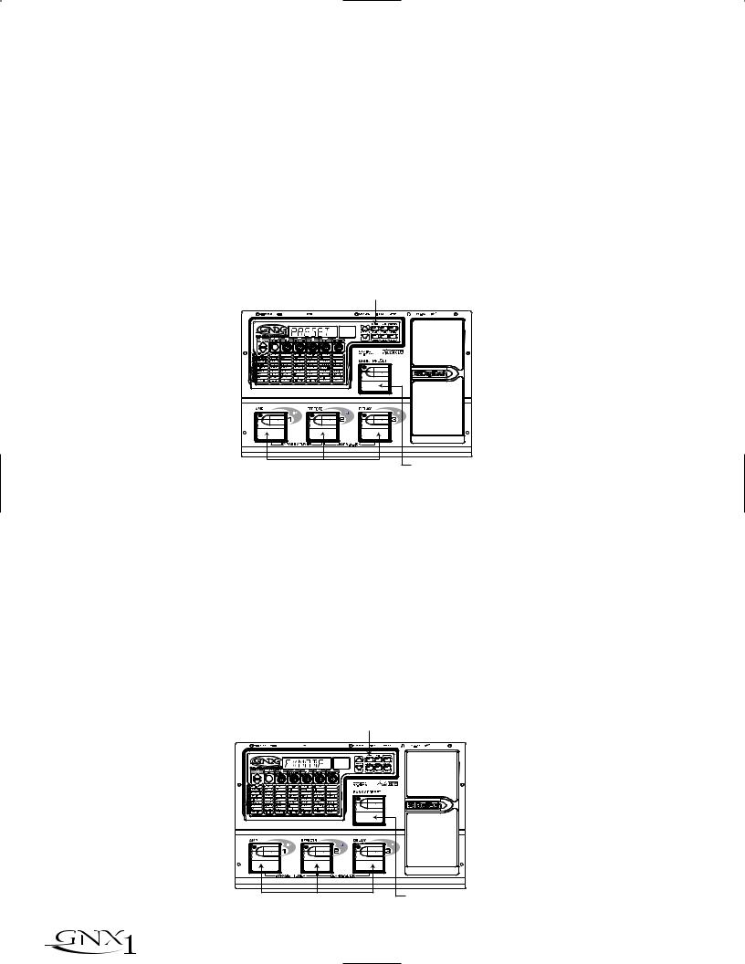
Preset Mode
Preset Mode is the default mode from the factory. In Preset mode, the 1-3 Footswitches will call up Presets in the currently selected Bank.The Bank Switch is used to select the 16 User/Factory Banks. Successive presses of the Bank/Preset switch will advance forward through all User/Factory Banks. Pressing and holding the Bank/Preset switch will scroll backwards through all User/Factory Banks. Once the desired Bank has been selected, the LEDs in the 1-3 Footswitches will flash indicating that a Preset within that bank needs to be selected in order to activate the Bank. If no Preset selection is made within 5 seconds,The GNX1 will return to the last Bank and Preset that had been active.
Modo de Preset
Este es el modo por defecto cuando la unidad sale de fábrica. En el modo de Preset, los pedales de disparo 1-3 cargarán los Presets en el banco activo en ese momento. El interruptor Bank se usa para elegir los 16 bancos de usuario / fábrica. Las pulsaciones sucesivas del interruptor Bank/Preset harán que vaya pasando por todos los bancos de usuario/fábrica. Si mantiene pulsado este interruptor irá pasando por los bancos hacia atrás. Una vez que haya elegido el banco que quiera, los pilotos de los pedales de disparo 1-3 parpadearán para indicar que tiene que elegir un preset dentro de ese banco para activarlo. Si no elige ningún preset en 5 segundos, el GNX1 volverá al último banco y preset que hubiese estado activo.
LED Off Indicates / Los LED apagados indican
Preset Mode |
el modo Preset |
Switches Select Presets |
Selects Banks |
Los interruptores eligen los Presets |
Elige los bancos |
FX Mode
FX mode is another mode of operation which can be used during a performance.The FX Mode button (located to the right of the Display) is used to switch between Preset and FX Modes.When the FX mode is active, the FX Mode button will light.In FX Mode, the 1-3 Footswitches toggle the designated Effects. Depending on which effects are active in the current Preset, these switches may have one or more LEDs lit indicating the status of these effects. Footswitch 1 toggles between the Green, Red, and Yellow amp channels. Footswitch 1 will light either green, red, or yellow indicating whether the Green Channel, Red Channel, or a Warped combination of the Green and Red Channels is active. Footswitch 2 turns on and off the Chorus/Mod Effects Module. Footswitch 3 turns on and off the Delay.The Bank/Preset switch is used to change Presets. Successive presses of the Bank/Preset switch will advance forward through all Factory and User Presets. Pressing and holding the Bank/Preset switch will scroll backwards through all Factory and User Presets.
Modo FX
El modo FX es otro modo operativo que puede usar durante una ejecución. El botón FX Mode (situado a la derecha de la pantalla) se utiliza para cambiar entre los modos Preset y FX. Cuando el modo FX está activo, el piloto del botón FX Mode se ilumina. En el modo FX, los pedales de disparo 1-3 cambian los efectos designados. Dependiendo de los efectos que estén activos en el preset elegido, estos interruptores puede que tengan un solo LED iluminado o varios, para indicar el estado de estos efectos. El pedal de disparo 1 cambia entre los canales de amplificador verde, rojo y amarillo. El pedal de disparo 1 se iluminará en esos colores para indicar que está activo el canal verde, el canal rojo o una combinación deformada de ambos canales. El pedal de disparo 2 activa o desactiva el módulo de efectos Chorus/Mod. El pedal de disparo 3 activa o desactiva el retardo. El interruptor Bank/Preset se usa para cambiar los Presets. Las pulsaciones sucesivas sobre este interruptor Bank/Preset harán que vaya pasando por los distintos presets de fábrica y de usuario. Si mantiene pulsado este interruptor irá pasando hacia atrás por los diferentes presets.
LED On indicates FX Mode
El piloto encendido indica el modo FX
Switches Toggle Effects |
Selects Presets |
|
Elige presets |
||
Interruptores activan efectos |
||
|
8 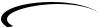
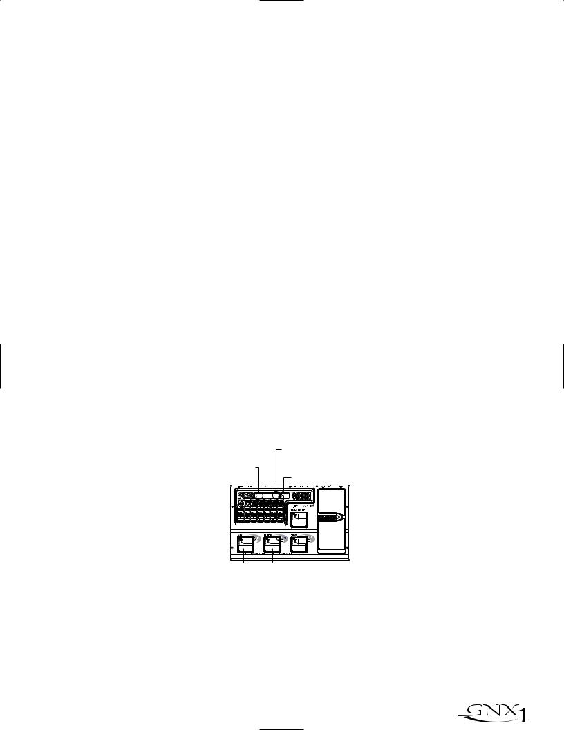
SECTION ONE - INTRODUCTION
The Footswitches
As explained previously, Preset Mode utilizes Footswitches 1-3 to select Presets, and the same switches will toggle Effects in FX Mode. However, these footswitches are also used to access other functions in the GNX1. Pressing the 1 and 2 Footswitches simultaneously, or pressing the currently lit Footswitch (in Preset mode) will bypass the GNX1. Pressing and holding the 1 and 2 Footswitches simultaneously will access the Tuner mode. Pressing the 2 and 3 Footswitches simultaneously will activate the Learn-A-Lick mode. In the Learn-A-Lick mode, the 1-3 switches will activate the various Learn-A-Lick functions.
The Expression Pedal
As you go through the different Presets in the GNX1, you will find that the expression pedal has different functions.This pedal can be assigned to control three different parameters in each Preset. Rocking the Expression Pedal back and forth will change the value of the assigned parameters.You can assign minimum and maximum values (stop points) for each parameter that you control with the pedal.The Expression Pedal also includes a feature called V- Switch which allows you to override the Parameters assigned to the Expression Pedal and replace its assignment with the Wah. See page 32 for more information on assigning the Expression Pedal.
Bypass Mode
The GNX1 can be bypassed for a clean, unprocessed, straight guitar tone. Bypass mode disengages all Modeling and effects.To bypass the GNX1 in Preset mode, press the Footswitch representing the currently active Preset (the 1-3 footswitch that is lit), or press Footswitch 1 and 2 simultaneously.To bypass the GNX1 while in FX Mode, press the 1 and 2 Footswitches simultaneously. When the GNX1 is bypassed, the Display will read BYPASS and all LEDs in the Matrix will turn off. Pressing any Footswitch will exit Bypass and return to the last Preset used. None of the Matrix or Programming buttons are available in Bypass mode.
Tuner Mode
The Tuner in the GNX1 allows you to quickly tune or check the tuning on your guitar. Enter Tuner mode by pressing and holding Footswitches 1 and 2 simultaneously.The Display will briefly show TUNER indicating that you are in Tuner mode.To begin tuning, play a note on your guitar (a harmonic at the 12th fret usually works best).The red numeric Display will show the note being played, and the green alpha-numeric display will indicate whether the note is sharp or flat. Arrows to the left (<<<) indicate the note is sharp and should be tuned down. Arrows to the right (>>>) indicate the note is flat and should be tuned up.When your note is in tune, the Display will read -><- .
Arrows Pointing Right indicate note is flat
Las flechas a la derecha indican nota bemolada
SECCIÓN Uno - INTRODUCCIÓN
Los pedales de disparo
Como hemos explicado anteriormente, el modo Preset usa los pedales de disparo 1-3 para elegir los Presets, y estos mismos interruptores cambian los efectos en el modo FX. Sin embargo, estos pedales de disparo se usan también para acceder a otras funciones en el GNX1. Si pulsa simultáneamente los pedales de disparo 1 y 2, o si pulsa el pedal de disparo iluminado en ese momento (en el modo Preset), anulará o dejará en bypass el GNX1. El mantener pulsados simultáneamente los pedales de disparo 1 y 2 le dará acceso al modo de afinador. El pulsar simultáneamente los pedales de disparo 2 y 3 activará el modo Learn-A-Lick. En este modo, los tres interruptores activarán las distintas funciones del Learn-A-Lick.
El pedal de expresión
Según vaya pasando por los distintos Presets del GNX1, observará que el pedal de expresión tiene distintas funciones. Puede asignar este pedal para controlar tres parámetros distintos en cada Preset. El girar el pedal de expresión adelante y atrás hará que cambie el valor de los parámetros asignados. Puede asignar valores mínimos y máximos (puntos de parada) para cada parámetro que vaya a controlar con el pedal. El pedal de expresión también incluye una función llamada V-Switch que le permite anular los parámetros asignados al pedal de expresión y sustituir esa asignación por el Wah.Vea en la página 32 más información acerca de la asignación del pedal de expresión.
Modo de anulación o bypass
El GNX1 puede ser anulado o colocado en bypass para conseguir un sonido de guitarra limpio, directo y sin procesado. Este modo bypass desactiva todos los efectos y el modelado. Para anular el GNX1 en el modo de Preset, pulse el pedal de disparo que represente al Preset activo (el pedal de disparo 1-3 que esté iluminado), o pulse simultáneamente el pedal de disparo 1 y 2. Para anular el GNX1 mientras esté en el modo FX, pulse simultáneamente los pedales de disparo 1 y 2. Cuando el GNX1 está en bypass, la pantalla le indicará BYPASS y todos los pilotos de la matriz se apagan. La pulsación de cualquiera de los pedales de disparo hará que salga de esta anulación y le devolverá al último preset usado. En el modo de anulación no puede usar ninguno de los botones de la matriz o de programación.
Modo de afinador
El afinador del GNX1 le permite rápidamente afinar o comprobar la afinación de su guitarra. Acceda a este modo manteniendo pulsados simultáneamente los pedales de disparo 1 y 2. En la pantalla aparecerá brevemente TUNER para indicarle que está en el modo de afinador. Para comenzar la afinación, toque una nota en su guitarra (un armónico en el 12avo traste suele funcionar bien). La pantalla roja numérica le mostrará la nota que esté tocando, y la pantalla alfanumérica verde le indicará si la nota está bemolada o sostenida. Las flechas a la izquierda (<<<) le indican que la nota está sostenida y que debería disminuir su tono. Las flechas a la derecha (>>>) indican que el tono está bemolado y que debería aumentarlo. Cuando la nota esté en su tono perfecto, en pantalla aparecerá -><- ..
Arrows Pointing Left indicate note is Sharp
Las flechas a la izquierda indican nota sostenida
Note played/Nota tocada
Press and Hold to Activate Tuner Mantenga pulsado para activar el afinador
In Tuner mode, you can select your tuning reference with the Data Up/Down buttons. The default factory setting is A=440 Hz.The tuning reference ranges from 427 Hz to 453 Hz, which is the equivalent of ± 50 cents (1/2 semitone) in either direction from 440 Hz.When you scroll below 427 Hz, you will also find alternate dropped tunings. Alternate tunings are REF A& (A=Ab), REF G (A=G), and REF G& (A=Gb).The display window will briefly flash the currently selected tuning preference.
Exit tuner mode by pressing any of the Footswitches.
En el modo de afinador, puede elegir su referencia de afinación con los botones Data arriba/abajo. El valor de fábrica por defecto es A=440 Hz. El rango de referencias de afinación va desde los 427 Hz a los 453 Hz, lo que es equivalente a ± 50 centésimas (1/2 semitono) en ambas direcciones del 440 Hz. Cuando pase por debajo de los 427 Hz, también encontrará algunas referencias de afinación alternativas a otros tonos. Estas afinaciones alternativas son REF A& (A=Ab), REF G (A=G) y REF G& (A=Gb). En la pantalla parpadeará brevemente la referencia de afinación elegida.
Para salir del modo de afinador no tiene más que pulsar cualquiera de los pedales de disparo.
 9
9

SECTION ONE - INTRODUCTION
Jam-A-Long
The Jam-A-Long feature allows you to connect a Tape, CD, or MP3 player to the GNX1, and Jam with your favorite artists.The signal from your Tape, CD, or MP3 player is output through the left and right, and headphone outputs of the GNX1. To use the Jam-A-Long feature, connect the headphone output of your Tape, CD, or MP3 player to the Jam-A-Long Input on the rear panel of the GNX1 using an 1/8” stereo cable.Then press play on your Tape, CD, or MP3 player.
Learn-A-Lick Mode
The Learn-A-Lick function allows you to record a 9 second passage of music and play it back as slow as 1/4 speed with no change in pitch. This is very useful for picking out the notes of a fast guitar solo.
There are 6 functions for Learn-A-Lick.They are:
•Stop (Controlled by the number 1 Footswitch)
•Rewind (Controlled by the number 2 Footswitch)
•Play (Controlled by the number 1 Footswitch)
•Record (Controlled by the number 3 Footswitch)
•Tempo Down (Controlled with Data Down button)
•Tempo Up (Controlled by the Data Up button)
Using Learn-A-Lick
1.Connect the output of your Tape, CD, or MP3 player’s headphone output to the Jam-A-Long input jack on the rear panel using an 1/8” stereo plug. Set the level of the player to a desired listening level.
2.Cue up to the passage you want to record and hit pause on the Tape, CD, or MP3 player.
3.Press and hold the number 2 and 3 Footswitches to enter Learn-A-Lick mode.The display will read: LALICK.
4.Release the pause button on your playback device and press the number 3 (Record) Footswitch. The display will read: RECORD and recording will begin. The red numeric Display will provide a time elapsed reference while recording is in process.When recording is completed, the phrase will be set to an auto-loop playback mode indicated by play in the Display.
5.Press stop or pause on the playback device.
6.Press the Data Down button to slow the playback down. Press the Data Up button to increase the playback speed to normal at 1/8 speed intervals.Your interval choices include: FULL, 7/8, 3/4, 5/8, 1/2, 3/8, and 1/4 speeds.
7.Pressing the number 2 (Rewind) Footswitch steps back through the loop at 1 second intervals.
8.The Expression Pedal will control output level of the recorded phrase.
9.To stop the playback, press the number 1 (Stop) Footswitch.
10.To resume playback, press the number 1 Footswitch again.
11.To record a new passage, press the number 3 (Record) Footswitch.
12.To exit the Learn-A-Lick mode, press and hold the number 2 and 3 Footswitches, or press the Exit button.
SECCIÓN Uno - INTRODUCCIÓN
Jam-A-Long
La función Jam-A-Long le permite conectar un reproductor de cinta, CD o MP3 al GNX1, e improvisar así con sus músicos favoritos. La señal de su reproductor de CD, MP3 o cinta es emitida a través de las salidas izquierda, derecha y de auriculares del GNX1. Para usar la función Jam-A-Long, conecte la salida de auriculares de su unidad reproductora a la Entrada Jam-A-Long del panel trasero del GNX1 usando un cable stereo de 3,5 mm. Después de conectarlo, pulse Play en su reproductor.
Modo Learn-A-Lick
La función Learn-A-Lick le permite grabar un pasaje de hasta 9 segundos de música y reproducirla hasta a 1/4 de la velocidad normal sin cambio en el tono. Esto resulta muy útil para hacer un dictado musical de las notas que forman un solo rápido de guitarra.
Este modo dispone de 6 funciones, que son:
•Stop (Controlado por el pedal de disparo número 1)
•Rebobinado (Controlado por el pedal de disparo número 2)
•Reproducción (Controlado por el pedal de disparo número 1)
•Grabación (Controlado por el pedal de disparo número 3)
•Tempo abajo (Controlado por el botón Data abajo)
•Tempo arriba (Controlado por el botón Data abajo)
Uso del Learn-A-Lick
1.Conecte la salida de auriculares de su reproductor de cinta, CD o MP3 a la toma de entrada Jam-A-Long del panel trasero usando un conector stereo de 3,5 mm. Ajuste el nivel del reproductor al nivel de escucha qe quiera.
2.Escuche y localice el pasaje que quiera grabar y pulse la pausa en el reproductor de cinta, CD o MP3 justo antes de dicho pasaje.
3.Mantenga pulsados los pedales de disparo 2 y 3 para acceder al modo Learn-A-Lick. En la pantalla aparecerá: LALICK.
4.Deje de pulsar el botón de pausa en su unidad reproductora y pulse el pedal de disparo 3 (grabación). En la pantalla aparecerá: RECORD y comenzará la grabación. La pantalla numérica roja le irá dando una indicación del tiempo transcurrido mientras se realiza la grabación. Cuando la grabación haya sido completada, la frase musical quedará ajustada en un modo de reproducción de bucle automático indicado por el mensaje play en la pantalla.
5.Pulse la parada o la pausa en la unidad reproductora.
6.Pulse el botón Data abajo para ralentizar la reproducción. Pulse el botón Data arriba para aumentar la velocidad de reproducción hasta la normal a intervalores de 1/8 de velocidad. Sus opciones posibles son: FULL, 7/8,
3/4, 5/8, 1/2, 3/8 y 1/4.
7.La pulsación del pedal de disparo 2 (Rebobinado) hará que se vaya desplazando hacia atrás por el bucle en intervalos de 1 segundo.
8.El Pedal de expresión controlará el nivel de salida de la frase musical grabada.
9.Para detener la reproducción, pulse el pedal de disparo 1 (Stop).
10.Para reiniciar la reproducción, pulse de nuevo el pedal de disparo 1.
11.Para grabar un nuevo pasaje, pulse el pedal de disparo 3 (grabación).
12.Para salir del modo Learn-A-Lick, mantenga pulsados los pedales de disparo 2 y 3, o pulse el botón Exit.
10 
 Loading...