


CD RECEIVER
RCD-M35DAB RCD-M33
OPERATING INSTRUCTIONS
CAUTION
RISK OF ELECTRIC SHOCK
DO NOT OPEN
CAUTION: TO REDUCE THE RISK OF ELECTRIC SHOCK, DO NOT REMOVE COVER (OR BACK). NO USER SERVICEABLE PARTS INSIDE. REFER SERVICING TO QUALIFIED SERVICE PERSONNEL.
The lightning flash with arrowhead symbol, within an equilateral triangle, is intended to alert the user to the presence of uninsulated “dangerous voltage” within the product’s enclosure that may be of sufficient magnitude to constitute a risk of electric shock to persons.
The exclamation point within an equilateral triangle is intended to alert the user to the presence of important operating and maintenance (servicing) instructions in the literature accompanying the appliance.
CLASS 1 LASER PRODUCT
WARNING:
TO PREVENT FIRE OR SHOCK
HAZARD, DO NOT EXPOSE THIS
APPLIANCE TO RAIN OR MOISTURE.
,,CLASS 1 ,, LASER PRODUCT
•DECLARATION OF CONFORMITY
We declare under our sole responsibility that this product, to which this declaration relates, is in conformity with the following standards:
EN60065, EN55013, EN55020, EN61000- 3-2 and EN61000-3-3.
Following the provisions of 73/23/EEC, 89/336/EEC and 93/68/EEC Directive.
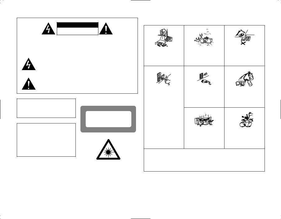
NOTE ON USE
• Avoid high temperatures. |
|
|
Allow for sufficient heat |
• Keep the set free from |
• Do not let foreign objects in |
dispersion when installed on a |
moisture, water, and dust. |
the set. |
rack. |
|
|
• Handle |
the |
power |
cord |
• Unplug the power cord when |
• Do not let insecticides, |
|
carefully. |
|
|
||||
|
|
not using the set for long |
benzene, and thinner come in |
|||
Hold |
the |
plug |
when |
|||
periods of time. |
contact with the set. |
|||||
unplugging the cord. |
|
|||||
|
|
|
||||
* (For sets with ventilation holes) |
• Never disassemble or modify |
|
|
• Do not obstruct the |
the set in any way. |
|
|
ventilation holes. |
|
• The ventilation should not be impeded by covering the ventilation openings with items, such as newspapers, table-cloths, curtains, etc.
• No naked flame sources, such as lighted candles, should be placed on the apparatus.
• Please be care the environmental aspects of battery disposal.
• The apparatus shall not be exposed to dripping or splashing for use.
• No objects filled with liquids, such as vases, shall be placed on the apparatus.
2
CAUTION
1. Handle the power supply cord carefully
Do not damage or deform the power supply cord. If it is damaged or deformed, it may cause electric shock or malfunction when used. When removing from wall outlet, be sure to remove by holding the plug attachment and not by pulling the cord.
2. Do not open the top cover
In order to prevent electric shock, do not open the top cover. If problems occur, contact your DENON DEALER.
3. Do not place anything inside
Do not place metal objects or spill liquid inside the CD receiver. Electric shock or malfunction may result.
NOTE:
This CD receiver uses the semiconductor laser. To allow you to enjoy music at a stable operation, it is recommended to use this in a room of 5°C (41°F) ~ 35°C (95°F).
Please, record and retain the Model name and serial number of your set shown on the rating label.
Model No. RCD-M35DAB/RCD-M33 |
Serial No. |
Thank you for purchasing this DENON CD receiver.
Please read the operation instructions thoroughly in order to acquaint yourself with the CD receiver and achieve maximum satisfaction from it.
TABLE OF CONTENTS
z Main Features ………………………………3 |
⁄2Playing CDs …………………………21 ~ 25 |
x Before Using ………………………………3 |
• Normal Playback ………………………21 |
c Cautions on Installation ……………………4 |
• Various Playback Functions ……22 ~ 24 |
v Connecting the Included Antennas ………4 |
• Edited Recording on Sides A |
b Connections ……………………………5, 6 |
and B of a Tape …………………………25 |
n Part Names and Functions ……………7, 8 |
⁄3Playing MP3/WMA …………………26 ~ 28 |
m Remote Control Unit …………………9, 10 |
• Normal Playback ……………………26, 27 |
, Cautions on Handling Discs ……………11 |
• Various Playback Functions ………27, 28 |
. Listening to Radio Programs ………11 ~ 14 |
⁄4Auto On Function …………………………28 |
⁄0Listening to DAB ……………………15, 16 |
⁄5Troubleshooting …………………………29 |
⁄1Using the Timer ……………………17 ~ 20 |
⁄6Specifications ……………………………29 |
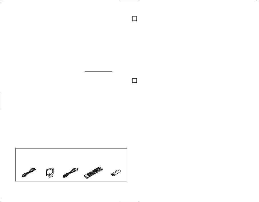
• ACCESSORIES
Check that the following parts are included in the package aside from the main unit:
qOperating instructions ……………………1 |
tDAB antenna (RCD-M35DAB only) ………1 |
|||
wService station list …………………………1 |
yRemote control unit (RC-999) ……………1 |
|||
eFM antenna…………………………………1 |
uR03/AAA batteries …………………………2 |
|||
rAM loop antenna …………………………1 |
|
|
||
e |
r |
t |
y |
u |
1MAIN FEATURES
1.Quality power for high quality sound
22W+22W (6 Ω/ohms, 1 kHz, T.H.D. 10%) high quality amplifier and terminals for large speakers.
2.MP3/WMA playback
Discs containing MP3 and/or WMA files can be played, and the track and artists names can be displayed during playback.
3.TONE and SDB control
TONE control is available for BASS and TREBLE separately and the SDB (Super Dynamic Bass) control enables powerful bass tones when listening at lower volume levels.
This unit has Source Direct position to turn off the SDB/TONE.
2BEFORE USING
Read the following before using the system.
•Before turning on the power
Check again that all connections are correct and that there are no problems with the connection cords. Be sure to unplug the power cord before connecting or disconnecting the connection cords.
Humming may be produced if this system is set near a TV or other audio equipment. If this happens, try changing the position of the equipment or the connection cords.
•Moving the system
Be sure to remove CD before moving the system. If a CD is left in the CD receiver, it may be scratched.
To prevent short-circuits or damage to the connection cords, always unplug the power cord and disconnect all connection cords to other audio equipment.
•Condensation (dew)
Condensation (water droplets) may be produced on internal optical lenses or discs in the following cases:
•Directly after a heater is turned on.
•When the system is in a steamy or humid room.
•When the system is moved abruptly from a cold place (room) to a warm room.
4.RDS compatible
Compatible with various RDS services, including program service name (PS) program type identification (PTY), traffic program identification (TP), clock time (CT) and radio text (RT).
5.Compatible with the system control
Connecting cassette deck (DRR-M33), the synchro-recording, timer operation can be made with easy operations.
6.DAB (Digital Audio Broadcasting) compatibility (RCD-M35DAB only)
The set is compatible with DAB broadcasts which offer excellent multipath and phasing characteristics and a sound quality and data transfer rate comparable to that of CDs.
•Should condensation occur:
The signals on the disc cannot be read and the system will not function properly. Remove the disc then let the system set with the power on. The condensation will evaporate in one hour or less, at which time the system will function normally.
•Store this instructions in safe place
After reading, store this instructions along with the warranty in a safe place. Also fill in the items on the back paper for your convenience.
•Illustrations in this manual
Note that some of the illustrations used for explanations in this manual may differ from the actual system.
3
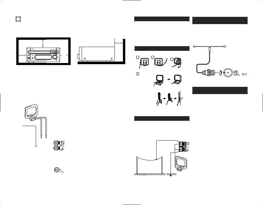
3 CAUTIONS ON INSTALLATION
Note:
For heat dispersal, do not install this equipment in a confined space such as a book case or similar unit.
|
|
|
Note |
|
|
4 CONNECTING THE INCLUDED ANTENNAS
Installing the FM indoor antenna |
|
Connecting an FM outdoor antenna |
||||||||
Tune in FM station (see page 12), set the |
If good reception cannot be achieved with the |
|||||||||
antenna so that distortion and noise is minimal, |
included FM antenna, use an FM outdoor |
|||||||||
then secure the tip of the antenna in this |
antenna. Connect an PAL-type connector to |
|||||||||
position using tape or a pin. |
the coaxial cable and connect the antenna to |
|||||||||
|
|
|
|
|
|
|
|
|
|
the FM COAX. (75 Ω/ohms) terminal. |
|
|
|
|
|
|
|
|
|
|
|
|
|
AM loop antenna |
Selecting a place for the FM/DAB outdoor |
|||||||
|
|
antenna |
||||||||
|
|
|
|
|
|
|
|
|
|
|
|
|
|
|
|
|
|
|
|
|
• Set the antenna so that it points towards the |
|
|
|
|
|
|
|
|
|
|
broadcast station’s transmitting antenna. |
|
|
|
|
|
|
|
|
|
|
Behind buildings or mountains, set the |
|
|
|
|
|
|
|
|
|
|
antenna in the position at which reception is |
|
|
|
|
|
|
|
|
|
|
best, and also try changing the direction of |
FM antenna |
the antenna. |
|||||||||
|
|
|
|
|
|
|
|
|
|
• Do not install the antenna under power lines. |
|
|
|
|
|
|
|
|
|
|
Doing so is extremely dangerous, as the |
|
|
|
|
|
|
|
|
|
|
power line could touch the antenna. |
|
|
|
|
|
|
|
|
|
|
• Install the antenna away from roads or train |
|
|
|
|
|
|
|
|
|
|
tracks to avoid noise from cars or trains. |
|
|
|
|
|
|
|
|
|
|
|
|
|
|
|
|
|
|
|
|
|
• Do not install the antenna too high, as it may |
|
|
|
|
|
|
|
|
|
|
be hit by lightning. |
|
|
|
|
|
|
|
|
|
|
|
Installing the AM loop antenna
Tune in an AM station (see page 12) and set the antenna as far from the system as possible to keep distortion and noise is minimal. In some cases, it is best to invert the polarities. AM broadcasts cannot be received well if the loop antenna is not connected or if it is set close to metal objects.
Assembling the AM loop antenna
1 |
2 |
Remove the vinyl tie and take out the
connection line.
4
a. With the antenna on top any stable surface.
Mount
b.With the antenna attached to a wall.
Connection to the AM loop antenna terminals.
3
Bend in the reverse direction.
Installation hole Mount on wall, etc.
Installing the DAB indoor antenna
(RCD-M35DAB only)
Find the position at which the reception sensitivity is best using the “Tuning Aid” function, then secure the tip of the DAB antenna in this position using a pin.
DAB antenna
Connecting an DAB outdoor antenna
(RCD-M35DAB only)
If good reception cannot be achieved with the included DAB indoor antenna, use an DAB outdoor antenna. Connect an F male type connector to the coaxial cable and connect the antenna to the DAB COAX. 75 Ω terminal.
Installing an AM outdoor antenna
Connect the signal wire from the AM outdoor antenna to the antenna terminal. Be sure to connect the signal ground wire to the  terminal. Also be sure to connect the included AM loop antenna.
AM outdoor antenna
AM loop
antenna
Signal ground
4
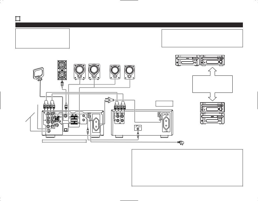
5 CONNECTIONS
(1) Connecting to Cassette deck (DRR-M33)
NOTE:
•This system includes digital circuitry which may cause interference such as color blotching or changes in the color on TVs. If this happens, move the system and the TV as far apart as possible.
Connecting the speaker systems
Connect the speaker system for the left channel (the left side as seen from the front) to the L terminals, the speaker system for the right channel to the R terminals. Refer to the instructions supplied with the speaker system for details. Be sure to use speaker systems with an impedance of 6 Ω/ohms or greater.
CAUTION:
•Whenever the power operation switch is in the STANDBY position, the unit is still connected to AC line voltage.
Please be sure to unplug the power cord when you leave home for, e.g.,a vacation, etc.
|
Speaker systems (SC-M73) |
|
|
||
Subwoofer |
(RCD-M35 only) |
Speaker systems (SC-M53) |
|||
Right |
Left |
||||
|
Right |
Left |
|||
|
|
|
|||
AM loop antenna |
|
|
|
|
|
DRR-M33 |
RCD-M35DAB |
Side by side installation
Install the sets as shown in one of these diagrams. In either case, be sure that the CD receiver’s ventilation holes are not obstructed.
FM antenna
DAB antenna (RCD-M35 only)
CD receiver (RCD-M35DAB/RCD-M33)
System operations
Such system operations as the timer and the auto power on functions, as well as remote control operations cannot be performed unless all the RCA pin-plug cords and system connector cords are connected between the units, so be sure to make all the connections properly as shown in the diagram. Also, disconnecting system connectors while the system is operating may result in malfunctions. Be sure to unplug the power cord before changing connections.
Cassette deck (DRR-M33)
(option) |
RCD-M35DAB |
DRR-M33
Stacking installation
Power plug
AC 230 V, 50 Hz
NOTES:
•Do not plug the power cord into the power outlet until all connections are completed. Be sure to interconnect the channels (L to L (white) and R to R (red)) properly, as shown on the diagram.
•Insert the plugs securely. Incomplete connections may result in noise.
•Be sure to connect the speaker cords between the speaker terminals and the speaker systems with the same polarities ( + to +, – to – ). If the polarities are switched, the sound at the center will be weak, the position of the different instruments will be unclear, and the stereo effect will be lost.
•After unplugging the power cord, wait about 5 seconds before plugging it back in.
•Note that setting the connection cords (pin-plug cords) next to the power cords may result in humming or other noise.
5
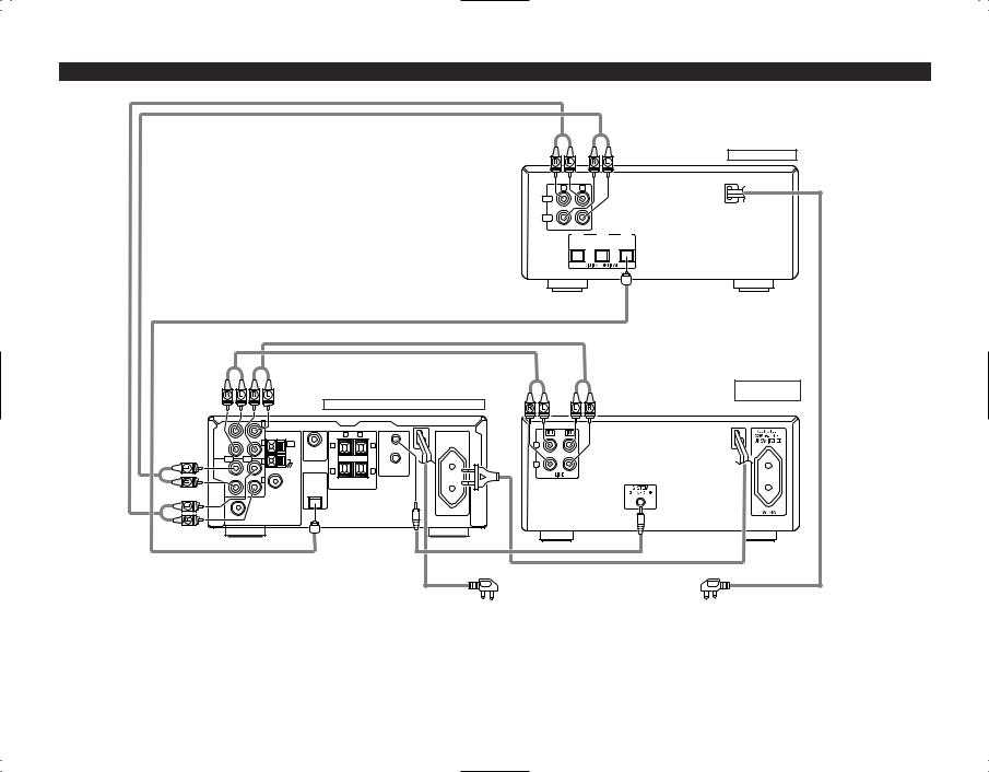
(2) Connecting to Cassette deck (DRR-M33) and CD recorder etc.
R L
IN
OUT
LINE
OUT IN-2 IN-1
CD receiver (RCD-M35DAB/RCD-M33) |
Power plug |
Power plug |
AC 230 V, 50 Hz |
AC 230 V, 50 Hz |
CD recorder etc.
Cassette deck |
(DRR-M33) |
(option) |
6
6 PART NAMES AND FUNCTIONS |
|
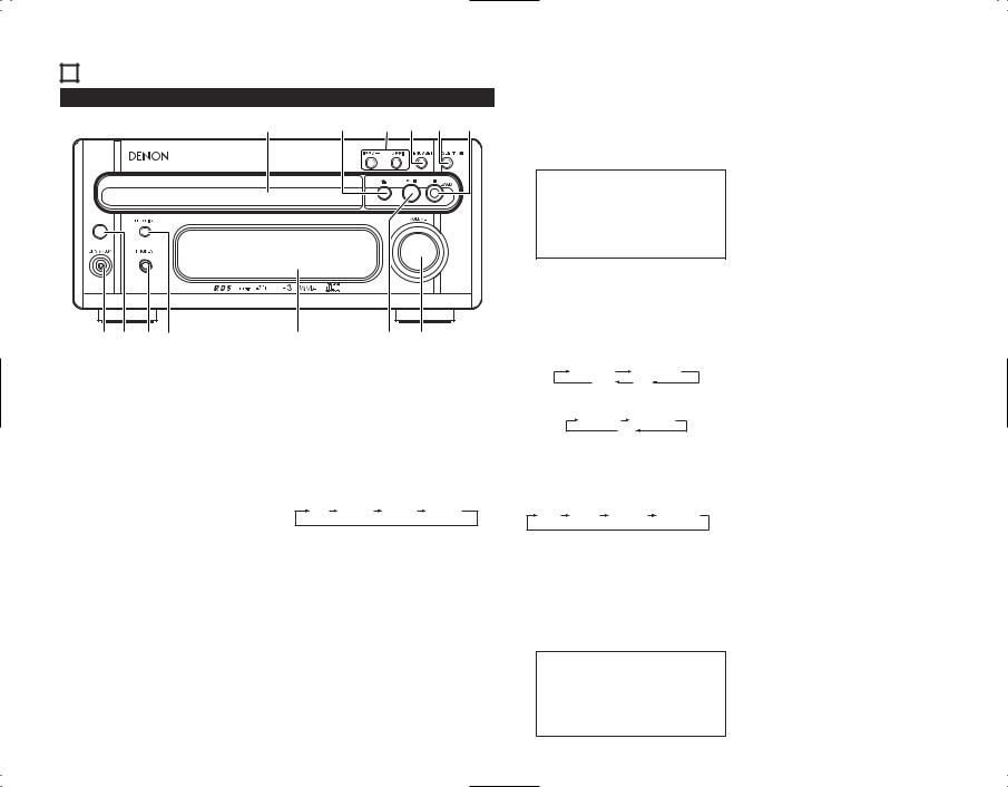
u VOLUME control |
|
|
• Use this to adjust the overall volume |
(1) Front Panel |
|
(Rotary Encorder System). |
|
• The volume increases when the control |
|
|
|
|
!3 |
!2 !1!0o i |
is turned clockwise (,) and decreases |
when it is turned counterclockwise (.). |
||
|
|
• The volume increases and decreases in |
|
|
35 steps from the minimum (VOLUME |
|
|
00) to the maximum (VOLUME MAX). |
|
|
|
|
|
|
|
|
|
|
|
NOTE: |
|
|
|
|
|
|
|
|
|
|
|
|
|
|
|
• Care must be taken when you adjust |
||||
|
|
|
|
|
|
|
|
|
|
|
the volume as the CD receiver is |
||||
|
|
|
|
|
|
|
|
|
|
|
equipped with an electronic volume |
||||
|
|
|
|
|
|
|
|
|
|
|
control. Turn the VOLUME control |
||||
|
|
|
|
|
|
|
|
|
|
|
slowly referring to the indication on |
||||
|
|
|
|
|
|
|
|
|
|
|
the display to adjust the volume. |
||||
|
|
|
|
|
|
|
|
|
|
i 2 /BAND button |
|
|
|||
|
|
|
|
|
|
|
|
|
|
( |
2 |
: CD stop button |
|
||
|
|
|
|
|
|
|
|
|
|
|
BAND : TUNER band button) |
||||
|
|
|
|
|
|
|
|
|
|
• In CD function, press this button to stop |
|||||
|
|
|
|
|
|
|
|
|
|
|
playback. |
|
|
|
|
qw er |
|
|
|
t |
|
y u |
|
• In TUNER function, use this button to |
|||||||
|
|
|
|
|
|
selecting the band. |
|
|
|||||||
|
|
|
|
|
|
|
|
|
|
|
For the RCD-M35DAB : |
|
|||
q Power operation switch (ON/STANDBY) |
w Remote sensor |
|
|
|
|
FM AUTO |
|
FM MONO |
|||||||
• This turns the power for the entire |
• When operating the remote control unit, |
|
|
|
|||||||||||
|
|
DAB |
|
AM |
|
||||||||||
system on and off. |
|
|
|
point it at this sensor. |
|
|
|
|
|
||||||
|
|
|
|
|
|
|
|
|
|
||||||
• Press this once to turn the power on, |
e PHONES (headphones jack) |
|
|
For the RCD-M33 : |
|
|
|||||||||
then press again to set the power to |
|
|
|
|
|
|
|
||||||||
STANDBY mode. |
|
|
|
• Plug the headphones into this jack. |
|
|
FM AUTO |
FM MONO |
|||||||
• The LED color changes as follows, |
• No sound is produced from the speakers |
|
|
|
AM |
|
|
||||||||
when headphones are plugged in. |
|
|
|
|
|
|
|||||||||
according to the condition: |
|
|
o SDB (Super Dynamic Bass)/TONE button |
||||||||||||
During power ON : green |
|
|
r FUNCTION button |
|
|||||||||||
During STANDBY : red |
|
|
|
|
• Press this button to select the preferred |
||||||||||
|
|
|
• Use this to select the input (function). |
||||||||||||
During TIMER STANDBY: orange |
|
|
sound of TONE CONTROL/SDB. Each |
||||||||||||
|
• The input changes in the following order |
|
|||||||||||||
The muting mode is set when the main |
|
time this button is pressed, the display |
|||||||||||||
each time this button is pressed: |
|
||||||||||||||
unit’s power button is pressed and when |
|
changes as follows: |
|
|
|||||||||||
|
|
|
|
|
|
|
|||||||||
the standby mode is canceled from the |
CD |
TUNER |
TAPE |
AUX |
|
SDB |
BASS |
TREBLE |
S.DIRECT |
||||||
remote control unit. The power indicator |
|
|
|
|
|
||||||||||
|
|
|
|
|
|
|
|
|
|
||||||
flashes green when in the muting mode, |
|
|
|
|
• You can switch the SDB on/off by using |
||||||||||
then stops flashing and turns green once |
t Display |
|
|
|
|||||||||||
the set is in the operational mode. |
|
• Refer to page 8. |
|
|
the +/– (up/down) button. |
|
|||||||||
If the indicator is flashing orange |
y 1/ 3 (play/pause) button |
|
• BASS and TREBLE can be adjusted by |
||||||||||||
(quickly): |
|
|
|
|
|
|
using the +/– (up/down) button. |
||||||||
The protective circuit is activated. |
|
• Press this button to start playing a disc. |
• When you select S.DIRECT (Source |
||||||||||||
If this happens, unplug the power cord |
When the disc tray is closed, playback |
|
Direct), SDB/TONE is switched off, and |
||||||||||||
to turn the indicator off, then check the |
begins when this button is pressed. |
|
the sound characteristic becomes flat. |
||||||||||||
input and output terminals on the rear |
• When pressed in STANDBY mode, the |
• SDB can be controlled powerful bass |
|||||||||||||
panel. |
Check in particular for short- |
power automatically turns on and |
|
tones when listening at lower volume |
|||||||||||
circuiting of the speaker cords. Once all |
playback begins (Auto On function). |
|
levels. |
|
|
|
|
||||||||
connections have been corrected, plug |
Press this button again to stop playback |
|
NOTE: |
|
|
|
|||||||||
the power cord. (Wait for at least 10 |
temporarily. |
|
|
|
|
|
|
||||||||
|
|
|
• The SDB should be deactivated when |
||||||||||||
seconds after turning the power off |
|
|
|
|
|
||||||||||
|
|
|
|
|
listening at higher volume levels. |
||||||||||
before turning it back on.) |
|
|
|
|
|
|
|
||||||||
|
|
|
|
|
|
|
Excessive bass at high volume levels |
||||||||
Power |
is |
supplied |
to |
the |
RCD- |
|
|
|
|
|
|||||
|
|
|
|
|
will result in a distorted sound and |
||||||||||
M35DAB/RCD-M33 even when the |
|
|
|
|
|
||||||||||
|
|
|
|
|
may cause damage to your set and |
||||||||||
power is in the standby mode (The clock |
|
|
|
|
|
||||||||||
|
|
|
|
|
speaker system. |
|
|
||||||||
is displayed in the clock display mode.) |
|
|
|
|
|
|
|
||||||||
|
|
|
|
|
|
|
|
|
|
||||||
!0MENU/ SET button
•When pressed in the standby mode, the standby mode is switched (the clock display is switched on and off).
•When pressed while the clock is displayed, the manual time setting mode is set. (This cannot be set while the clock is displayed in the standby mode.)
•Switches the display of the timer setting menu on and off.
•When the function is set to FM and the CT tuning mode is set, the mode switches to the auto time setting mode.
•When the function is set to TUNER and an FM station is being received, if pressed for more than 1 second, the display switches to the AUTO PRESET menu.
!18 /– , +/ 9 button
(8, 9 : CD automatic search
|
reverse/forward button |
+ , – |
: TUNER up/down button) |
•Use the 8 and 9 buttons to move to the beginning of a specific track while in CD function.
•Use the +/– button to select radio stations while in TUNER function.
•In TUNER function, press the 2 /BAND and + buttons at the same time to change the Preset mode, the 2 /BAND and – buttons at the same time to change the Tuning mode.
•Use the +/– button when you adjust tone control (BASS or TREBLE) and you select menu function (display, time, timer, or set up).
!25 (open/close) button
•Press this button to open and close the disc tray.
•When pressed once, the disc tray opens out, and when pressed again, the disc tray closes. If a disc is loaded, the total number of tracks and total playing time of the disc are displayed several seconds after the disc tray is closed.
•When pressed in STANDBY mode, the CD receiver’s power turns on.
!3Disc tray
• Load discs here.
7
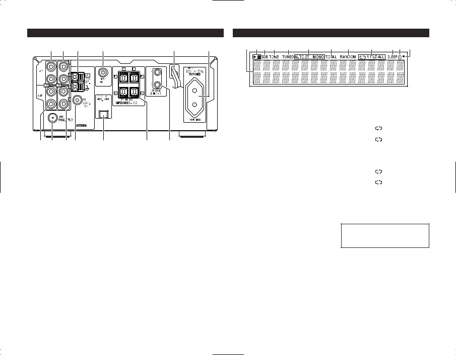
(2) Rear Panel |
(3) Display |
@6@5@4 |
@3 |
@2 |
@1 |
q w e r |
t |
y |
u |
i |
o |
!0!1 !2 |
!4!5!6!7 |
!8 |
!9 @0 |
!4AUX IN (analog input) jacks
• This is an input terminal.
!5DAB antenna terminal (ANTENNA TERMINAL DAB)
(RCD-M35DAB only)
• Connect the FM antenna here.
!6AUX OUT (analog output) jacks
• This is an output terminal for recording.
!7FM antenna terminal (ANTENNA TERMINAL FM)
• Connect the FM antenna here.
!8Digital output jack (DIGITAL OPTICAL OUT)
•Digital data is output in optical form from this jack.
!9Speaker terminals (SPEAKERS)
• Use these to connect the speakers.
@0System connectors
(SYSTEM CONNECTOR 1 and 2)
•When connecting the DRR-M33, connect these connectors to system connectors on other system components.
(Use the system cords included with the other components.)
@1AC OUTLET
•When using in combination with the DRR-M33, connect to the AC outlet on the CD receiver (RCD-M35DAB/RCD- M33) or one of the other components (100W MAX).
@2Power cord
• Plug this cord into a wall power outlet.
@3MONO OUT terminal (SUB WOOFER)
•Connector jack for subwoofer with builtin amplifier (super woofer), etc.
@4AM antenna terminal (ANTENNA TERMINAL AM)
• Connect the AM antenna here.
@5TAPE OUT (analog output) jacks
• This is an output terminal for recording.
@6TAPE IN (analog input) jacks
• This is an input terminal.
qSegment
The selected functions, volume, reception band, reception frequency, RDS data, time, and timer settings are displayed here.
w 1/ 3
1 (the play indicator) lights when a disc is playing, and 3 (the pause indicator) lights when pause mode is set.
eSDB
This lights when SDB mode is on.
rTONE
This lights when the TONE is adjusted.
tTUNED
This lights when a station is tuned in properly.
y AUTO / ST / MONO
These display the FM reception mode.
ST |
: This lights when a stereo |
|
program is received in the FM |
|
AUTO mode. |
MONO |
: This lights when a monaural |
|
program is received in the FM |
|
AUTO mode and when the |
|
BAND button is pressed, |
|
setting the FM MONO mode. |
AUTO |
: This lights when the BAND |
|
button is pressed, setting the |
|
FM AUTO mode. |
uTOTAL
Lights when the total remaining time or the total number of tracks remaining on the disc is displayed on the segment.
iRANDOM
“RANDOM” lights during random play.
o  / 1 / FLD / ALL
This changes as follows each time the REPEAT button is pressed.
•When the function is set to CD and the mode is not the folder mode:
1st press |
: |
1 (single-track repeat) |
|
|
is displayed. |
2nd press : |
ALL (1 disc all track |
|
|
|
repeat) is displayed. |
3rd press |
: |
Nothing is displayed. |
•When the function is set to CD and the folder mode is set (only valid for discs containing MP3 and/or WMA files):
1st press |
: |
1 (single-track repeat) |
|
|
is displayed. |
2nd press : |
FLD (all track in a |
|
|
|
folder repeat) is displayed. |
3rd press |
: |
Nothing is displayed. |
!0SLEEP
This lights when the sleep timer is operating.
!1
NOTE:
•The timer standby mark (“  ”) does not light if the current time
and the timer have not been set.
The timer will operate when this is lit.
!2Remote control signal indicator
Flashes when remote control signals are received.
8

7 REMOTE CONTROL UNIT
The RCD-M35DAB/RCD-M33 comes with a system remote control unit (RC-999).
•The supplied remote control unit (RC-999) is for use with the RCD-M35DAB/RCD-M33 unit only.
•If the cassette deck (DRR-M33) is connected to the main unit, you may operate each of the above components using its respective remote control unit (refer to pages 9,10).
(1) Inserting the batteries
qOpen the battery compartment cover of the remote control unit.
Press the knob and open the cover in the direction of the arrow.
wInsert the two R03 (AAA) batteries, following the + and – marks in the battery compartment.
e Close the cover of the battery compartment.
Cautions on Batteries
•Use R03 (AAA) batteries in this remote control unit.
•Replace the batteries with new ones after approximately 1 year, though this depends on the frequency with which the remote control unit is used.
•Replace the batteries with new ones if the unit does not operate when the remote control unit is operated from nearby, even if the batteries are less than a year old.
•Be sure to insert the batteries in the proper direction, following the “ < ” and “ > ” marks in the battery compartment.
•To avoid damage or leakage of battery fluid:
•Do not use a new battery with an old one.
•Do not use two different types of batteries.
•Do not short-circuit, take apart, heat or dispose of batteries in flames.
•Remove the batteries when you do not plan to use the remote control unit for an extended period of time.
•If the battery fluid should leak, carefully wipe off the fluid from the inside of the battery compartment, then insert new batteries.
(2) Using the Remote Control Unit
30° |
7m |
|
30°
•The remote sensor is located on the CD receiver. Point the remote control unit at the remote sensor as shown on the diagram when operating it.
•The remote control unit will operate from a direct distance of approximately 7 meters, but this distance will be shortened if obstacles are present or if operated at an angle. (The remote control unit will operate at an angle of up to 30° in either direction.)
NOTES:
•The remote control unit may not operate if the remote sensor is exposed to direct sunlight or the strong light from a lighting fixture, or if there is an obstacle between the remote control unit and the remote sensor.
•Do not press buttons on the remote control unit and on the set at the same time. Doing so could result in malfunctions.
•If the remote control unit is pointed away from the re-mote sensor during continuous operations (such as when turning the volume up or down), the operation will stop. If this happens, point the remote control unit at the remote sensor and press the button again.
(3) Remote Control Unit Part Names and Functions
|
|
|
q SLEEP button |
||
|
q |
|
|
• Press this button to set the sleep timer. |
|
|
|
w OFF button |
|||
w |
|
#5 |
|||
|
|
• Use this switch to set the power to |
|||
r e |
#4 |
STANDBY mode. |
|||
|
|
#3 |
e TUNER button |
||
|
t |
#2 |
• Press this button to set the function |
||
y |
TUNER mode. |
||||
u |
#1 |
r CD button |
|||
|
|||||
|
|
|
|
• Press this button to set the function CD |
|
|
|
|
|
mode. |
|
|
|
|
t PROG/DIRECT button |
||
|
i |
|
|
• Press this button to switch between |
|
|
|
|
PROGRAM and DIRECT play. |
||
|
|
#0 |
y EDIT button |
||
|
|
|
In CD function : |
||
|
|
@9 |
• Press this button for edited recording on a |
||
|
|
|
|
tape, dividing the tracks onto sides A and |
|
|
o |
@8 |
|
B according to the length of the tape. |
|
|
|
In TUNER function : |
|||
|
|
|
|
||
|
|
@7 |
• Press this button to input the station |
||
|
|
name. |
|||
|
!0 |
@6 |
u CALL button |
||
!1 |
@5 |
• Use this button to confirm the |
|||
|
!2 |
@4 |
|
programmed song. |
|
|
i Number buttons |
||||
!3 |
|
||||
|
!4 |
@3 |
|
In CD function : |
|
|
|
• Press these buttons to specify the |
|||
!5 |
@2 |
desired track. |
|||
In TUNER function : |
|||||
|
!6 |
@1 |
|
• Press these buttons to recall preset |
|
!7 |
@0 |
station. |
|||
|
!8 |
!9 |
o FOLDER (+ / –) button |
||
For MP3/WMA discs with the function set to CD:
• Select the folder.
• In the play and pause modes, the first track in the selected folder is selected.
9

!0MENU/ SET button
•When pressed in the standby mode, the standby mode is switched (the clock display is switched on and off).
•When pressed while the clock is displayed, the manual time setting mode is set. (This cannot be set while the clock is displayed in the standby mode.)
•Switches the display of the timer setting menu on and off.
•When the function is set to FM and the CT tuning mode is set, the mode switches to the auto time setting mode.
•When the function is set to TUNER and an FM station is being received, if pressed for more than 1 second, the display switches to the AUTO PRESET menu.
!1ENTER/ MEMO button
•Press this button to enter editing settings.
•Press this button to preset memory.
!28 /CH–
(automatic search) button
In CD function :
•Move to the beginning of current Track or previous Track.
In TUNER function :
•Use this button to recall preset stations on the tuner.
!36 /TU–
(manual search / rewind) button
In CD function :
•The manual search operation is performed.
In TUNER function :
•Use this button to selecting the station. In TAPE function :
•Press this button to rewind the front side of the tape. (The back side of the tape is fast-forwarded.) Also use this button to search for the beginning of the current selection when playing in the forward (1) direction, or to search for the beginning of the following selection when playing in the reverse (0) direction.
!4SDB /TONE button
•Press this button to adjust SDB (Super Dynamic Bass) and TONE.
!5DIMMER button
•Use this to adjust the brightness of the main unit‘s display. Can be switched in 4 steps, from OFF to always on.
!6DAB/ RDS button
When the function is set to TUNER-FM
•Use this button to automatically tune to stations using the radio data system.
 RDS
RDS  PTY
PTY  TP
TP
OFF
When the function is set to TUNER-DAB (RCD-M35DAB only)
•Used to display the reception sensitivity, to sort the service list, to select the dynamic range and to display the DAB version.
 TUNING AID
  STATION ORDER DAB VERSION
 DRC
DRC 
!70 (reverse play) button (TAPE)
•Press this to start playback or recording in the reverse direction.
!81 (forward play) button (TAPE)
•Press this to start playback or recording in the forward direction.
!92 (stop) button (TAPE)
•Press this button to stop playback or recording.
@01/ 3 (play/pause) button (MD)
• Not supported.
@1PTY button
•Press this button after selecting “PTY” with the RDS button to select one of the 29 program types.
@2CLOCK button
•Press this to switch the clock display between on and off.
@3TIME/ DISPLAY button
For audio CDs with the function set to CD:
•Press this button during the play or pause mode to switch the time display.
elapsed time |
remaining time |
per track |
for the track |
total remaining time on the disc
(During programmed playback, indicate the total remaining time of the programmed tracks.)
For MP3/WMA discs containing track information with the function set to CD:
•Press this button during the play or pause mode to switch the track information.
 file name
  Title / Artist
Title / Album
With the function set to TUNER, and in the FM and RDS modes:
• Press to switch the display below.
frequency |
(PS) |
PTY |
RT |
CT |
|
PS:This is displayed when the radio station currently being received is one named using the procedure described in “P13 – Presetting or naming radio stations”.
@49 /CH+
(automatic search) button
In CD function :
• Move to the beginning of Next Track.
In TUNER function :
•Use this button to recall preset stations on the tuner.
@57 /TU+
(manual search / fast-forward) button
In CD function :
• The manual search operation is performed.
In TUNER function :
• Use this button to selecting the station.
In TAPE function :
•Press this button to fast-forward the front side of the tape. (The back side of the tape is rewind.) Also use this button to search for the beginning of the following selection when playing in the forward (1) direction, or to search for the beginning of the current selection when playing in the reverse (0) direction.
@6MUTE button
•Mutes the speaker output. When operated while the output is muted, the mute mode is canceled.
@72 (stop) /BAND button
•In CD function, press this button to stop playback.
•In TUNER function, use this button to selecting the band.
For the RCD-M35DAB :
 FM AUTO
  FM MONO
DAB  AM
AM 
For the RCD-M33 :
 FM AUTO
  FM MONO
AM 
@8VOLUME button
•Use these buttons to adjust the volume.
•The volume increases when the • button is pressed and decreases when the ª button is pressed.
@9CD 1/ 3 (play/pause) button
•Press this button to play or pause of the CD player.
#0CLEAR/ DEL button
In CD function :
•Press this button to clear the track from the program.
In TUNER function :
•Press this button to erase the station name.
#1FOLDER MODE button
•For MP3/WMA discs with the function set to CD, switches the play mode between disc and folder.
#2REPEAT button
• Press this button for repeat playback.
#3RANDOM button
•Press this button to set the tracks in random order.
#4LINE button
•Press this button to switch the function LINE .
The input changes in the following order each time this button is pressed.
 TAPE
TAPE  AUX
AUX 
#5POWER ON button
•Use this switch to turn on the power of the entire system.
10
 Loading...