

Page 1
1
NETWORK AUDIO VIDEO PLAYER
DN-V1700
OPERATING INSTRUCTIONS
MODE D’EMPLOI
INSTRUCCIONES DE OPERACION
STOP
SKIP
POWER PCC
ACCESS
HDD
OSD/
TIME SET
PLAY /
EJECT
PAUSE
SELECT
NETWORK AUDIO VIDEO PLAYER
DN-V1700
FOR ENGLISH READERS PAGE 006 ~ PAGE 037
POUR LES LECTEURS FRANCAIS PAGE 038 ~ PAGE 069
PARA LECTORES DE ESPAÑOL PAGINA 070 ~ PAGINA 101
Page 2

2
IMPORTANT TO SAFETY
WARNING:
TO PREVENT FIRE OR SHOCK HAZARD, DO NOT
EXPOSE THIS APPLIANCE TO RAIN OR MOISTURE.
CAUTION:
1. Handle the power supply cord carefully
Do not damage or deform the power supply cord. If it is damaged
or deformed, it may cause electric shock or malfunction when
used. When removing from wall outlet, be sure to remove by
holding the plug attachment and not by pulling the cord.
2. Do not open the top cover
In order to prevent electric shock, do not open the top cover.
If problems occur, contact your DENON DEALER.
3. Do not place anything inside
Do not place metal objects or spill liquid inside the network audiovideo player.
Electric shock or malfunction may result.
Please, record and retain the Model name and serial number of your
set shown on the rating label.
Model No. DN-V1700 Serial No.
NOTE:
This network audio-video player. uses the semiconductor laser. To
allow you to enjoy music at a stable operation, it is recommended to
use this in a room of 5 °C (41 °F) ~ 35 °C (95 °F).
CAUTION:
USE OF CONTROLS OR ADJUSTMENTS OR REFORMANCE OF
PROCEDURES OTHER THAN THOSE SPECIFIED HEREIN MAY
RESULT IN HAZARDOUS RADIATION EXPOSURE.
THE NETWORK AUDIO-VIDEO PLAYER SHOULD NOT BE
ADJUSTED OR REPAIRED BY ANYONE EXCEPT PROPERLY
QUALIFIED SERVICE PERSONNEL.
This device complies with Part 15 of the FCC Rules. Operation
is subject to the following two conditions: (1) This device may
not cause harmful interference, and (2) this device must accept
any interference received, including interference that may
cause undesired operation.
This Class A digital apparatus meets all requirements of the
Canadian Interference-Causing Equipment Regulations.
Cet appareil numérique de la classe A respecte toutes les
exigences du Règlement sur le matériel brouilleur du Canada.
CAUTION:
• The ventilation should not be impeded by covering the
ventilation openings with items, such as newspapers, tablecloths, curtains, etc.
• No naked flame sources, such as lighted candles, should be
placed on the apparatus.
• Please be care the environmental aspects of battery
disposal.
• The apparatus shall not be exposed to dripping or splashing
for use.
• No objects filled with liquids, such as vases, shall be placed
on the apparatus.
Copyrights / Droits d’auteur / Derechos de Autor
2
It is prohibited by law to reproduce, broadcast, rent or play discs in
public without the consent of the copyright holder.
2
La reproduction, la diffusion, la location, le prêt ou la lecture
publique de ces disques sont interdits sans le consentement du
détenteur des droits d’auteur.
2
De acuerdo con las leyes está prohibido reproducir, emitir, alquilar
o interpretar discos en público sin la autorización del propietario de
los derechos de autor.
Page 3

3
ENGLISH FRANCAIS ESPAÑOL
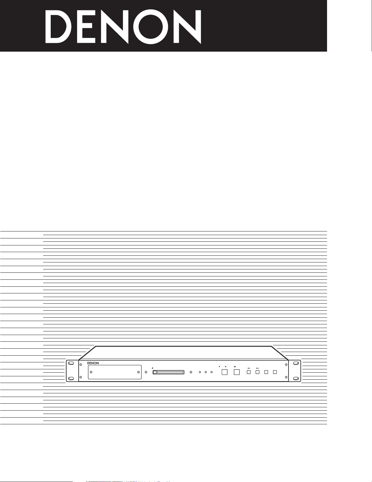
FRONT PANEL
PANNEAU AVANT
PANEL FRONTAL
REAR PANEL
PANNEAU ARRIERE
PANEL TRASERO
REMOTE
SERIALPARALLEL
DIGITAL
COMPOSITE
COMPONENT
SYNC. (VITC
)
DC IN (+6V
)
POWER
MASTER
SLAVE
YC
B
CR
IN
OUT
ONOFF
S-VIDEO
ANALOGBALANCED UNBALANCED
L
L
R
R
ETHERNET
AUDIO OUTPUT
VIDEO OUTPUT
RS232C
RS422A
q
wer
yi!0 !1 !3
!4
!5
t
u o !6!2
STOP
SKIP
POWER PCC
ACCESS
HDD
OSD/
TIME SET
PLAY /
EJECT
PAUSE
SELECT
NETWORK AUDIO VIDEO PLAYER
DN-V1700
q
we rtyuio!0
!1
!2
Page 4

4
SAFETY INSTRUCTIONS
1. Read Instructions – All the safety and operating instructions
should be read before the product is operated.
2. Retain Instructions – The safety and operating instructions
should be retained for future reference.
3. Heed Warnings – All warnings on the product and in the
operating instructions should be adhered to.
4. Follow Instructions – All operating and use instructions should
be followed.
5. Cleaning – Unplug this product from the wall outlet before
cleaning. Do not use liquid cleaners or aerosol cleaners.
6. Attachments – Do not use attachments not recommended by
the product manufacturer as they may cause hazards.
7. Water and Moisture – Do not use this product near water – for
example, near a bath tub, wash bowl, kitchen sink, or laundry
tub; in a wet basement; or near a swimming pool; and the like.
8. Accessories – Do not place this product on an unstable cart,
stand, tripod, bracket, or table. The product may fall, causing
serious injury to a child or adult, and serious damage to the
product. Use only with a cart, stand, tripod, bracket, or table
recommended by the manufacturer, or sold with the product.
Any mounting of the product should follow the manufacturer’s
instructions, and should use a
mounting accessory
recommended by the
manufacturer.
9. A product and cart
combination should be
moved with care. Quick
stops, excessive force,
and uneven surfaces may
cause the product and cart
combination to overturn.
10. Ventilation – Slots and openings in the cabinet are provided for
ventilation and to ensure reliable operation of the product and to
protect it from overheating, and these openings must not be
blocked or covered. The openings should never be blocked by
placing the product on a bed, sofa, rug, or other similar surface.
This product should not be placed in a built-in installation such
as a bookcase or rack unless proper ventilation is provided or
the manufacturer’s instructions have been adhered to.
11. Power Sources – This product should be operated only from the
type of power source indicated on the marking label. If you are
not sure of the type of power supply to your home, consult your
product dealer or local power company. For products intended
to operate from battery power, or other sources, refer to the
operating instructions.
12. Grounding or Polarization – This product may be equipped with
a polarized alternating-current line plug (a plug having one blade
wider than the other). This plug will fit into the power outlet
only one way. This is a safety feature. If you are unable to
insert the plug fully into the outlet, try reversing the plug. If the
plug should still fail to fit, contact your electrician to replace your
obsolete outlet. Do not defeat the safety purpose of the
polarized plug.
13. Power-Cord Protection – Power-supply cords should be routed
so that they are not likely to be walked on or pinched by items
placed upon or against them, paying particular attention to
cords at plugs, convenience receptacles, and the point where
they exit from the product.
15. Outdoor Antenna Grounding – If an outside antenna or cable
system is connected to the product, be sure the antenna or
cable system is grounded so as to provide some protection
against voltage surges and built-up static charges. Article 810
of the National Electrical Code, ANSI/NFPA 70, provides
information with regard to proper grounding of the mast and
supporting structure, grounding of the lead-in wire to an
antenna discharge unit, size of grounding conductors, location
of antenna-discharge unit, connection to grounding electrodes,
and requirements for the grounding electrode. See Figure A.
16. Lightning – For added protection for this product during a
lightning storm, or when it is left unattended and unused for
long periods of time, unplug it from the wall outlet and
disconnect the antenna or cable system. This will prevent
damage to the product due to lightning and power-line surges.
17. Power Lines – An outside antenna system should not be
located in the vicinity of overhead power lines or other electric
light or power circuits, or where it can fall into such power lines
or circuits. When installing an outside antenna system,
extreme care should be taken to keep from touching such
power lines or circuits as contact with them might be fatal.
18. Overloading – Do not overload wall outlets, extension cords, or
integral convenience receptacles as this can result in a risk of
fire or electric shock.
19. Object and Liquid Entry – Never push objects of any kind into
this product through openings as they may touch dangerous
voltage points or short-out parts that could result in a fire or
electric shock. Never spill liquid of any kind on the product.
20.
Servicing – Do not attempt to service this product yourself as
opening or removing covers may expose you to dangerous
voltage or other hazards. Refer all servicing to qualified
service personnel.
21.
Damage Requiring Service – Unplug this product from the
wall outlet and refer servicing to qualified service
personnel
under the following conditions:
a) When the power-supply cord or plug is damaged,
b) If liquid has been spilled, or objects have fallen into the
product,
c) If the product has been exposed to rain or water,
d) If the product does not operate normally by following the
operating instructions. Adjust only those controls that are
covered by the operating instructions as an improper
adjustment of other controls may result in damage and will
often require extensive work by a qualified technician to
restore the product to its normal operation,
e) If the product has been dropped or damaged in any way, and
f) When the product exhibits a distinct change in performance
– this indicates a need for service.
22. Replacement Parts – When replacement parts are required, be
sure the service technician has used replacement parts
specified by the manufacturer or have the same characteristics
as the original part. Unauthorized substitutions may result in
fire, electric shock, or other hazards.
23. Safety Check – Upon completion of any service or repairs to this
product, ask the service technician to perform safety checks to
determine that the product is in proper operating condition.
24. Wall or Ceiling Mounting – The product should be mounted to a
wall or ceiling only as recommended by the manufacturer.
25. Heat – The product should be situated away from heat sources
such as radiators, heat registers, stoves, or other products
(including amplifiers) that produce heat.
FIGURE A
EXAMPLE OF ANTENNA GROUNDING
AS PER NATIONAL
ELECTRICAL CODE
ANTENNA
LEAD IN
WIRE
GROUND
CLAMP
ELECTRIC
SERVICE
EQUIPMENT
ANTENNA
DISCHARGE UNIT
(NEC SECTION 810-20)
GROUNDING CONDUCTORS
(NEC SECTION 810-21)
GROUND CLAMPS
POWER SERVICE GROUNDING
ELECTRODE SYSTEM
(NEC ART 250, PART H)
NEC - NATIONAL ELECTRICAL CODE
Page 5

5
ENGLISHFRANCAISESPAÑOL
NOTE ON USE / OBSERVATIONS RELATIVES A L’UTILISATION / NOTAS SOBRE EL USO
• Avoid high temperatures.
Allow for sufficient heat dispersion when
installed on a rack.
• Eviter des températures élevées.
Tenir compte d’une dispersion de chaleur
suffisante lors de l’installation sur une
étagère.
• Evite altas temperaturas.
Permite la suficiente dispersión del calor
cuando está instalado en la consola.
• Keep the set free from moisture, water,
and dust.
• Protéger l’appareil contre l’humidité,
l’eau et lapoussière.
• Mantenga el equipo libre de humedad,
agua y polvo.
• Do not let foreign objects in the set.
• Ne pas laisser des objets étrangers dans
l’appareil.
• No deje objetos extraños dentro del
equipo.
• Do not let insecticides, benzene, and
thinner come in contact with the set.
• Ne pas mettre en contact des
insecticides, du benzène et un diluant
avec l’appareil.
• No permita el contacto de insecticidas,
gasolina y diluyentes con el equipo.
• Unplug the power cord when not using
the set for long periods of time.
• Débrancher le cordon d’alimentation
lorsque l’appareil n’est pas utilisé
pendant de longues périodes.
• Desconecte el cordón de energía cuando
no utilice el equipo por mucho tiempo.
• Do not obstruct the ventilation holes.
• Ne pas obstruer les trous d’aération.
• No obstruya los orificios de ventilación.
• Handle the power cord carefully.
Hold the plug when unplugging the cord.
• Manipuler le cordon d’alimentation avec
précaution.
Tenir la prise lors du débranchement du
cordon.
• Maneje el cordón de energía con
cuidado.
Sostenga el enchufe cuando desconecte
el cordón de energía.
• Never disassemble or modify the set in
any way.
• Ne jamais démonter ou modifier
l’appareil d’une manière ou d’une autre.
• Nunca desarme o modifique el equipo de
ninguna manera.
✽ (For sets with ventilation holes)
Page 6

6
ENGLISH
— TABLE OF CONTENTS —
z
Features ................................................................................7
x
Handling Precautions ............................................................7
c
Compatible Flash Memory Card List ....................................8
v
Playback Medium Contents .........................................9 ~ 11
b
Preparations ..................................................................12, 13
n
Name and Functions of Parts .......................................14, 15
m
Synchronization Connections........................................15, 16
,
Connections to External Devices........................................17
.
Setting the Internal Clock ...................................................18
⁄0
Main Unit LED Indicators....................................................19
• ACCESSORIES
The following accessories should be included in addition to the main unit. Please check before using.
q AC adaptor ..........................................................................1
w Power cord..........................................................................1
e Video cord ...........................................................................1
r Audio cord (stereo)..............................................................1
t Rack mount fittings .........................1 each for left and right
y DC plug disconnection prevention
fittings .....................................................1 each for A and B
u IC memory card protector...................................................1
i Feet .....................................................................................4
o Mount screws ............................................Short: 1, Long: 9
• For rack mount fittings...........................................Long: 6
• For DC plug disconnection prevention
fittings .....................................................Short: 1, Long: 1
• For IC memory card protector ...............................Long: 2
!0 Operating instructions.........................................................1
qwe
⁄1
Current ................................................................................19
⁄2
Playback Using the Main Unit Controls ........................20, 21
⁄3
Internal Hard Disk Drive .............................................21 ~ 23
⁄4
Serial Remote Control Terminal..................................23 ~ 28
⁄5
Parallel Remote Control Terminal .................................28, 29
⁄6
Playing Script Files........................................................30, 31
⁄7
Network Interface.................................................................32
⁄8
On-Screen Display (OSD) ...........................................33 ~ 35
⁄9
Troubleshooting.............................................................36, 37
¤0
Main Specifications.............................................................37
rty
ui
Page 7

ENGLISH
7
1
MAIN FEATURES
05. Various playback controls are realized the script (program)
language.
06. Video Frame synchronization by VITC.
07. DN-V1700 is equipped with FTP server function through 10
Base-T/100 Base-TX Ethernet connector.
08. RS232C/RS422A serial connector (switchable) is equipped.
09. Parallel I/O terminal for external controller and tally operations.
10. DN-V1700 is equipped with a 2.5-inch sized hard disk drive.
2
HANDLING PRECAUTIONS
Condensation
2
Definition
Condensation is the same phenomenon as water droplets
forming on windows of a heated room in the winter.
2
Conditions causing condensation
If the set is brought from the cold outdoors in the winter into
a heated room or if the temperature in the room where the set
is located rises suddenly due to a strong heater, for example,
water droplets will form on the operating parts inside the set
and the set will no longer operate normally.
Condensation can also form in the summer if the set is
exposed to the wind coming directly from an air conditioner. If
so, move the set to a different place.
2
What to do if condensation occurs
If condensation should occur, let the set sit for a while without
turning on the power. (Usually the set will become functional
in one to two hours, though this depends on the surrounding
conditions.)
Backing up data
If the playback medium (hard disk drive, etc.) should itself fail, you
will not be able to recover the data. We strongly suggest to you
make backups.
Please back up the data on the hard disk drive before turning in
the set for repairs.
Note that DENON will not accept any responsibility whatsoever
for loss of or changes to data during repairs.
Installation Precautions
2
Using the set or other electronic equipment including
microprocessors at the same time as a tuner or TV may result
in noise in the tuner’s or TV’s sound or disturb the TV picture.
If this should happen, take the following measures:
• Move the set as far from the tuner or TV as possible.
• Move the tuner’s or TV’s antenna wire away from the set’s
power cord and the input/output connection cords (pin-plug
cords).
• Noise or disturbed picture tends to occur particularly when
using internal antennas or 300 Ω/ohms fader cords. We
recommend using an external antenna and 75 Ω/ohms
coaxial cable.
300 Ω/ohms fader cord 75 Ω/ohms coaxial cable
2
To remove dirt from the cabinet or control panel, wipe gently
using a soft cloth.
• Before using a chemical-impregnated cloth, read its
cautions.
2
Exposing the set to benzene, thinner or other organic solvents
or pesticides could mar the surface. Avoid using such
products.
Cleaning
01. The DN-V1700 uses Flash Memory card as the playback
medium, achieving highly reliable operation without moving
mechanism. (At IC card operation.)
02. Various I/O and control terminals are prepared in 1U rack
mountable size.
03. The unit uses globally accepted MPEG format for high
compression ration and with superior sound and video quality.
04. DN-V1700 also supports linear PCM audio playback.
2
The set is equipped with a hard disk drive. Do not use it near
devices that generate magnetic forces (speakers, etc.).
When moving the unit
Turn off the power, unplug the power cord, and disconnect all
external connection cords (connection cords to other devices,
etc.) before moving the unit. Failure to do so could damage the
cords, leading to fire or electric shock.
Also, be careful not to drop the unit or subject it to strong shocks,
as doing so could damage the unit.
Page 8

ENGLISH
8
3
COMPATIBLE FLASH MEMORY CARD LIST
2 The DN-V1700 uses Flash Memory card as playback media.
2 Please use an adaptor to use a Compact Flash card.
Card to be used (playback media)
Nominal
Capacity
Compact Flash
Hagiwara Sys-com
Lexar Media
Model
0032 MB CF032-200 CFC-032MBA (H00AB)
0064 MB CF064-200 CFC-064MBA (H00AA)
0096 MB
…
CFC-096MBA (H00AB)
0128 MB CF128-12-360 CFC-128MBA (H00AA)
0160 MB CF160-12-360 CFC-160MBA (H00AB)
0192 MB CF192-12-360 CFC-192MBA (H00AB)
0256 MB CF256-12-360 CFC-256MBA (H00AA)
0320 MB CF320-12-360 CFC-320MBA (H00AB)
0384 MB
…
CFC-384MBA (H00AA)
0512 MB CF512-12-360 CFC-512MBA (H00AA)
*1) Compact Flash™ is a registered trademark of SanDisk.
✽ The above table is valid as of May, 2002. Some cards may no longer be produced or sold.
✽ DN-V1700 does not support memory card with a capacity less than 32 MB.
NOTE:
Unlike digital still cameras, DN-V1700 continuously accesses large amount of data, resulting in higher level of technical
requirements for selection of Flash Memory card.
Some commercially available Flash Memory cards do not fulfill the data transfer rate requirement, and we listed here the memory
cards that have sufficient access speed.
If a non-listed memory card is used, it may happened that playback would randomly halt or stop, and playback many not be
possible.
Compact Flash
Model
Hagiwara Sys-com
…
…
…
…
…
…
…
…
…
…
ATA
Model
0640 MB
……
0768 MB
……
1024 MB
……
1280 MB
……
1536 MB
……
1792 MB
……
2048 MB
……
ATC-640MBA (H00AA)
ATC-768MBA (H00AA)
ATC-1G02BA (H00AA)
ATC-1G28BA (H00AA)
ATC-1G53BA (H00AA)
ATC-1G79BA (H00AA)
ATC-2G04BA (H00AA)
Page 9

ENGLISH
9
(2) Video/still picture and audio formats
The DN-V1700 corresponds to the following format.
2 VIDEO and AUDIO file format [File names are given the extension: mpg]
System: ISO/IEC 13818-1 MPEG2 PS (Program Stream)
CBR (Constant Bit Rate) or VBR (Variable Bit Rate) Max. 10 Mbps*
VIDEO: ISO/IEC 13818-2 MPEG2 MP@ML 720 x 480 (NTSC)
AUDIO: ISO/IEC 11172-3 MPEG1 – Audio Layer 2
Sampling Frequency: 48 kHz, 44.1 kHz
File size: From 2 MB to 2 GB
2 VIDEO (with no AUDIO) file format [File names are given the extension: mpv]
VIDEO: ISO/IEC 13818-2 MPEG2 MP@ML ES (Elementary Stream) 720 x 480 (NTSC)
CBR (Constant Bit Rate) or VBR (Variable Bit Rate) Max. 10 Mbps*
File size: From 2 MB to 2 GB
2 Still picture file format [File names are given the extension: mpi]
Still picture: ISO/IEC 13818-2 MPEG2 MP@ML ES (Elementary Stream) 720 x 480 (NTSC)
1 frame only (Intra frame picture)
File size: From 4 kB to 224 kB
2 AUDIO (with no VIDEO) file format
AUDIO: ISO/IEC 11172-3 MPEG1 – Audio Layer 2
Sampling frequency: 48 kHz, 44.1 kHz
[File names are given the extension: mpa]
or
AUDIO: 16 bit Linear PCM
Sampling frequency: 48 kHz, 44.1 kHz
[File names are given the extension: wav]
File size: Playback time is 2 seconds or more. MAX 2 GB
✽ Special Notes
1) As mentioned in Note in page 8, operation at the maximum bit rate may not be possible if a memory card with lower access speed
is used.
2) You will also have to pay attention to the quality of video encoder.
Even though high quality memory card and higher bit rate is used, use of low quality encoder system may result in intermittent or
low quality video playback.
4
PLAYBACK MEDIUM CONTENTS
2 Format type
DN-V1700 accepts FAT 16 and FAT 32 formatted media, and media formatted in other type such as FAT 12 or NTFS will not work with
DN-V1700.
Cluster size should be 2kB or larger.
Please use FAT 16. If the media is larger than 2GB, please use FAT 32.
Only primary partition is recognized. Do not create extended partition.
2 Cluster size
The cluster size is the smallest unit of data when writing on Flash Memory cards.
The cluster size may change when cards are formatted on PCs or any devices other than the DN-V1700.
(1) Formatting
Page 10

ENGLISH
10
(3) Directories and file organization
In order that DN-V1700 operates properly, data should be written on the media in prescribed directories and in the specified manner.
Directories other than what are prescribed here, should not be created.
2 File name
A file name is eight characters or less with alpha-numeric characters according to ASCII code.
Long file name (VFAT) is not supported.
Number: from 0 to 9, alphabet: A to Z, Symbol: _
2 Extension
• VIDEO and AUDIO Program stream: mpg
• VIDEO (with no AUDIO) Elementary stream: mpv
• Still picture: mpi
• AUDIO (with no VIDEO) MPEG1 Layer 2 Audio: mpa
• AUDIO (with no VIDEO) 16 bit Linear PCM: wav
• Script file (play list file): dsc
2 Directories
All the files should be stored in the following directories only.
No duplicate file names are accepted.
The maximum file numbers of VIDEO, SCRIPT, and an AUDIO directory is 999.
The number of the maximum files of a PICTURE directory is 9999.
Please be sure to create the VIDEO, SCRIPT, AUDIO and PICTURE directories irrespective of the existence of a file (If the media is
formatted by DN-V1700, these directories will automatically be created).
The SYS directory is used by the DN-V1700 to output log files, etc.
✽ DN-V1700 recognizes both fs = 48 kHz and 44.1 kHz for mpg, mpa and wav audio files.
It is, however, recommended that you stick to either of sampling frequencies.
DN-V1700 will need c.a.1 second to switch the sampling frequency mode.
\ROOT
\VIDEO
✽✽✽.mpg (MPEG2-PS (VIDEO and AUDIO))
✽✽✽.mpv (MPEG2-ES (VIDEO (with no AUDIO)))
\AUDIO
✽✽✽.mpa (MPEG1 Layer2 AUDIO (with no VIDEO))
✽✽✽.wav (16bit Linear PCM AUDIO (with no VIDEO))
\PICTURE
✽✽✽.mpi (MPEG2-ES (Still picture))
\SCRIPT
✽✽✽.dsc (script file (play list file))
\SYS
✽✽✽.log (log file)
Page 11

ENGLISH
11
(4) Playing time
Recorded
content
Recording bit rate
Recording time
(example)
Video
+
audio
3 Mbps
(including 128 kbps x 2 ch audio)
2 min.
The playing time on the DN-V1700 depends on the capacity of the card and the playback bit rate.
Below is a description of basic methods for calculating the playing time and some examples.
2 Video + audio
Video playback bit rate (kbps) x playing time (sec.) = capacity of video portion
Audio playback bit rate (kbps) x playing time (sec.) x 2 (2 channels, left and right) = capacity of audio portion
Capacity of video portion + capacity of audio portion = Total capacity (kbit)
Total capacity (kbit) ÷ 8 = Total capacity (kByte)
Total capacity (kByte) ÷ 1024 = Total capacity (required card capacity) (MByte)
2 Video only
Video playback bit rate (kbps) x playing time (sec.) = Total capacity (kbit)
Total capacity (kbit) ÷ 8 = Total capacity (kByte)
Total capacity (kByte) ÷ 1024 = Total capacity (required card capacity) (MByte)
2 Still pictures
Still pictures capacity per image (kbit) ÷ 8 = Total capacity (kByte)
Total capacity (kByte) ÷ 1024 = Total capacity (required card capacity) (MByte)
2 Audio only (MPEG1 Audio Layer 2)
Audio playback bit rate (kbps) x playing time (sec.) x 2 (2 channels, left and right) = Total capacity (kbit)
Total capacity (kbit) ÷ 8 = Total capacity (kByte)
Total capacity (kByte) ÷ 1024 = Total capacity (required card capacity) (MByte)
2 Audio only (16 bit Linear PCM)
16 (bits) x sampling frequency (kHz) x playing time (sec.) x 2 (2 channels, left and right) = Total capacity (kbit)
Total capacity (kbit) ÷ 8 = Total capacity (kByte)
Total capacity (kByte) ÷ 1024 = Total capacity (required card capacity) (MByte)
[Example] Calculations of required capacities
Capacity
045 MB
Formula
3 x 120 ÷ 8 = 45
8 Mbps
(including 128 kbps x 2 ch audio)
2 min. 120 MB 8 x 120 ÷ 8 = 120
Audio only
MPEG 128 kbps 60 min. 113 MB 128 x 3600 x 2 ÷ 8 ÷ 1024 = 113
16 bit Linear PCM 48 kHz
10 min.
225 MB 16 x 48 x 600 x 2 ÷ 8 ÷ 1024 = 225
Still pictures 100 kB x no. pictures 500 049 MB 100 x 500 ÷ 1024 = 49
Still pictures
+
audio
100 kB x no. pictures
Audio MPEG 128 kbps
500
60 min.
162 MB 100 x 500 ÷ 1024 + 128 x 3600 ÷ 8 ÷ 1024 = 162
Page 12

ENGLISH
12
2 Checking the accessories
Check that all the accessories are included, referring to the
section “Accessories”.
2 Mounting on the rack
The DN-V1700 uses a rack-mount chassis (1U).
Use the included rack mount fittings as shown below to
mount the DN-V1700 on a 1U type rack mount rack.
NOTE:
When mounting the DN-V1700 on the rack, be sure to use
guide rails or shelf boards, etc., on the rack side to prevent
weight from being applied to the front of the DN-V1700.
The weight of the DN-V1700 cannot be supported only
with the fittings.
Also take sufficient considerations for the installation
environment, for example with respect to heat from other
devices (use forced ventilation, etc.).
2 Mounting the feet
Set the feet in the holes in the bottom of the set and push them at the center to insert them fully.
✽ The feet are press-fitted into the set, so they cannot be removed once mounted.
5
PREPARATIONS
Page 13

ENGLISH
13
2 Connecting the AC adaptor
2
1
Set the DN-V1700’s power switch to the OFF position.
POWER
ONOFF
Insert the power cord’s inlet into the AC adaptor’s AC input side.
3
Insert the AC adaptor’s DC plug into the DN-V1700’s DC jack.
Mount the DC plug disconnection prevention fittings (A and B) so
that the DC plug does not come disconnected.
Short screw
Long
screw
4
Plug the power cord into a power outlet.
Cautions on the AC Adaptor
•
Be sure to use the included AC adaptor.
•
Be sure to set the DN-V1700’s power switch to the OFF position when plugging in and unplugging the AC adaptor.
•
Note that plugging in the AC adaptor while the set’s power is turned on may damage the set or the IC memory card.
•
Do not pull on the DC plug cord with excessive force when the DC plug disconnection prevention fittings (A and B) are connected.
Doing so will damage the DC plug cord, possibly damaging the set.
Page 14

ENGLISH
14
6
NAME AND FUNCTIONS OF PARTS
(See page 3.)
(1) Front panel
q
Internal HDD
This is the internal hard disk drive.
w
IC memory card eject button (EJECT)
Press this to eject the IC memory card. Be sure the stop
mode is set or the power is turned off when ejecting the IC
memory card. In particular, never eject the card when the IC
memory card access lamp is flashing or lit (except when the
access lamp is flashing to indicate an error).
If the eject operation is performed when the card is being
accessed, the data may be lost and the set may be
damaged. Should this happen, “reboot!!!” may output from
the set’s video output and the set may be reset forcibly.
e
IC memory card slot (drive)
This is where the IC memory card is inserted. Be sure to
load the IC memory card securely.
r
POWER indicator
This lights when the set’s power is on.
t
IC memory card access lamp (ACCESS PCC)
This lights or flashes when the IC memory card is being
accessed.
y
Hard disk access lamp (ACCESS HDD)
This lights or flashes when the hard disk drive is being
accessed.
u
PLAY/PAUSE button
In the normal play mode with a file selected, press this in the
stop or pause mode to start playback. When pressed during
playback, the pause mode is set.
i
STOP button
Press this to stop playback. During script playback, press the
button for 2 seconds or more to stop script playback.
o
SKIP 8 button
Press this to search for the previous file in the currently set
sorting order.
!0
SKIP 9 button
Press this to search for the next file in the currently set
sorting order.
!1
OSD/TIME SET button
Press this to turn the OSD (on-screen display) on and off.
Use this button together with the STOP button to set the
time.
!2
SELECT button
Use this to change the current directory.
Use this button together with the STOP button to change
the current drive.
(2) Rear panel
q
PARALLEL REMOTE terminal
This is the terminal for parallel control from an external
device.
w
SERIAL REMOTE terminal
This is the terminal for serial control from an external device.
Use a serial straight through cable for connection to a
computer.
e
RS232C/RS422A selector switch
Use this switch to select the SERIAL REMOTE terminal’s
interface.
Set to the back for RS422A, to the front for RS232C.
r
ETHERNET terminal
This is a 10 Base-T/100 Base-TX LAN connector.
t
DIGITAL AUDIO OUTPUT terminal
This is an SPDIF digital audio output. Connect an amplifier,
etc., allowing digital input.
y
ANALOG AUDIO OUTPUT terminal (XLR)
This is a balanced type analog audio output using an XLR
type connector.
[Pin layout] 1: Ground (G)
2: Hot (H)
3: Cold (C)
u
ANALOG AUDIO OUTPUT terminal (RCA)
This is an analog audio output. Connect it to an amplifier or
monitor speaker with an analog audio input using an RCA
pin-plug cable.
i
COMPOSITE VIDEO OUTPUT terminal (BNC)
This is a composite video output. Connect it to a monitor
display equipped with a composite video input using a 75
Ω/ohms BNC cable. The connected device must be
terminated at 75 Ω/ohms.
Page 15

ENGLISH
15
o
COMPOSITE VIDEO OUTPUT terminal (RCA)
This is a composite video output. Connect it to a monitor
display equipped with a composite video input using a 75
Ω/ohms RCA cable. The connected device must be
terminated at 75 Ω/ohms.
!0
S-VIDEO OUTPUT terminal
This is an S-Video output terminal. Connect it to a monitor
display equipped with an S-Video terminal using an S-Video
cable.
!1
COMPONENT VIDEO OUTPUT terminal
This is a component video output. Connect it to a monitor
display equipped with a component video input.
!2
MASTER/SLAVE selector switch
Use this to select the set’s operating mode, master or slave.
The setting is detected when the power is turned on, so if it
this switch is operated, turn the power off then back on.
7
SYNCHRONIZATION CONNECTIONS
The DN-V1700 allows synchronized playback in units of frames using external VITC time code signals. Synchronized playback is also
possible using a slave generator function that generates time codes synchronized to video signals (vertical/horizontal synchronizing
signals) not including VITC time code signals.
When and only when using the DN-V1700 as a slave device of another device equipped with the VITC signal generating function, set the
MASTER/SLAVE selector switch on the rear panel to the SLAVE side. In all other cases (when not synchronizing the DN-V1700 with
another device or when synchronizing another device using the DN-V1700’s VITC signals), set the MASTER/SLAVE selector switch to the
MASTER side.
[Example of connections - 1] Synchronization connection of three DN-V1700s
SYNC. (VITC
)
MASTER
SLAVE
IN
OUT
DN-V1700 MASTER
SYNC. (VITC
)
MASTER
SLAVE
IN
OUT
DN-V1700 SLAVE
SYNC. (VITC
)
MASTER
SLAVE
IN
OUT
DN-V1700 SLAVE
SYNC. (VITC
)
MASTER
SLAVE
IN
OUT
SYNC. (VITC
)
MASTER
SLAVE
IN
OUT
In this example, the time code generated by the master unit synchronizes the two slave units. Set the master unit’s selector switch to
MASTER, the slave units’ selector switches to SLAVE.
✽ When the flash ROM has been set to the slave generator mode by serial or LAN external control command, the slave generator mode
must be cancelled.
!3
VITC IN terminal
This is the VITC input terminal for operating the set in the
slave mode. It is terminated at 75 Ω/ohms. The input signal
level is 1Vp-p.
!4
VITC OUT terminal
This is the VITC output terminal. The output is for
synchronization with another device.
!5
POWER switch
Set this to the ON side to turn the set’s power on.
!6
DC IN terminal
This is the power input terminal. Connect the included AC
adaptor here.
Page 16

ENGLISH
16
[Example of connections - 2] Using an external device as the master unit
SYNC. (VITC
)
MASTER
SLAVE
IN
OUT
DN-V1700 SLAVE
SYNC.(VITC)
OUT
SYNC. (VITC
)
MASTER
SLAVE
IN
OUT
DN-V1700 SLAVE
SYNC.(VITC)
OUT
SYNC. (VITC
)
MASTER
SLAVE
IN
OUT
In this example, a device with an external VITC output is used as the master unit to synchronize two slave units.
✽ When the flash ROM has been set to the slave generator mode by serial or LAN external control command, the slave generator mode
must be cancelled.
External VITC signal generating
device (sync. generator, etc.)
[Example of connections - 3] Synchronizing to the B.B. (black burst) signals of an external device not including VITC signals
SYNC. (VITC
)
MASTER
SLAVE
IN
OUT
DN-V1700 SLAVE1
B.B.
OUT
SYNC. (VITC
)
MASTER
SLAVE
IN
OUT
DN-V1700 SLAVE2
B.B.
OUT
SYNC. (VITC
)
MASTER
SLAVE
IN
OUT
In this example, two slave units are synchronized with the B.B. (black burst) signals of an external device not including VITC signals.
The first DN-V1700 generates VITC signals synchronized to the vertical/horizontal synchronizing signals included in the external devices’
B.B. signals and emits the signals from the SYNC. (VITC) OUT terminal.
✽ In this example, the flash ROM of DN-V1700 slave 1 must be set to the slave generator mode by serial or LAN external control
command.
External device
NOTES:
•
The DN-V1700’s time code signal is compatible with VITC (Vertical Interval Time Code) standards.
It is not compatible with LTC (Longitudinal Time Code) standards.
•
When connecting the DN-V1700 for synchronization as the master device, the maximum number of units that can be connected
as slave units is 4.
•
When multiple units are connected for synchronization, if the power of one of the slave units in the middle of the chain is turned
off, synchronized playback is not possible on subsequent slave units either.
•
When using the external device’s composite video signals instead of the B.B. signals, synchronization may be disturbed due to the
large DC fluctuation element in the video signal.
Page 17

ENGLISH
17
8
CONNECTIONS TO EXTERNAL DEVICES
1. Connect the PARALLEL REMOTE terminal to conduct parallel control.
2. Connect the SERIAL REMOTE terminal to conduct external serial control.
*1) Use a serial straight-through cable for connection with a computer.
*2) This terminal is for both RS232C and RS422A. Be sure to set the RS232C/RS422A selector switch to the proper position.
3. Connect the ETHERNET terminal to conduct 10 Base-T/100 Base-TX LAN control.
4. Connect the DIGITAL AUDIO OUTPUT terminal to use the digital audio output.
5. Connect the ANALOG AUDIO OUTPUT terminals to use the analog audio output.
*1) There are three sets of analog audio outputs that output the same audio signals: two sets of RCA outputs and one set of XLR
outputs.
6. Use the COMPOSITE VIDEO OUTPUT terminal to connect the DN-V1700 to the composite video input of an video monitor (TV, etc.).
*1) To connect to a device other than a video monitor, the connected device must be terminated at 75 Ω/ohms.
*2) The BNC and RCA terminals output the same composite video signal.
7. Use the S-VIDEO OUTPUT terminal to connect the DN-V1700 to a video monitor (TV, etc.) with an S-Video input. The brightness signal
(Y) and color difference signal (C) are output separately, resulting in a more defined image than with the composite video signal.
8. Use the COMPONENT VIDEO OUTPUT terminal to connect the DN-V1700 to a video monitor (TV, etc.) with a component video input.
The brightness signal (Y) and color difference signals (C) are divided and the different color difference signals are output separately,
resulting in a more defined image than with the composite S-Video signal.
REMOTE
SERIALPARALLEL
DIGITAL
COMPOSITE
COMPONENT
SYNC. (VITC
)
DC IN (+6V
)
POWER
MASTER
SLAVE
YC
B
CR
IN
OUT
ONOFF
S-VIDEO
ANALOGBALANCED UNBALANCED
L
L
R
R
ETHERNET
AUDIO OUTPUT
VIDEO OUTPUT
RS232C
RS422A
RS232C terminal on
a computer or
RS232C or RS422A
terminal on a serial
controller
SPDIF input on a
digital amplifier,
etc.
Composite video
input on a video
monitor
Component video input
on a video monitor
Y Cb (U, B-Y) Cr (V, R-Y)
Parallel controller LAN
Analog audio input
on a video
monitor’s amplifier,
etc.
S-Video input on
a video monitor
Refer to
“Synchronization
Connections”.
Page 18

ENGLISH
18
9
SETTING THE INTERNAL CLOCK
The DN-V1700 is equipped with an internal clock. Set the clock before using the DN-V1700.
The clock can be set either by using the controls on the DN-V1700 or by serial port control. For instructions on serial port control, see the
“14 Serial Remote Control Terminal” section.
2 Setting the date and time using the controls on the DN-V1700
Connect the DN-V1700’s video output to an external monitor and turn on the power.
1
In the stop mode, press the OSD/TIME SET button while pressing the STOP
button.
✽ When the key lock mode is set, cancel the mode using the “KL” serial
command.
STOP
OSD/
TIME SET
2
The following appears on the external monitor:
“TIME SET MODE”
“yyyy/mm/dd-hh:mm:ss” (current date/time)
“yyyy/mm/dd-hh:mm:ss” (set date/time)
“daylight saving **” (see note below)
“yyyy” flashes.
TIME SET MODE
2001/07/30-16:58:05
2001/07/30-16:45:28
daylight saving xx
Use the SKIP button to set the year (A.D.).
SKIP
3
Press the SELECT button to move to the months’ place.
SELECT
4
Repeat steps 3 and 4 to set the date and time.
5
6
Once the setting is completed, press the OSD/TIME SET button. “TIME SET OK”
is displayed and the setting is completed.
✽ Press the STOP button to cancel the setting.
TIME SET OK
2 Quick set:
Press the PLAY/PAUSE button after step 1 above to reset the seconds to 0.
2 Daylight savings time:
The DN-V1700’s current daylight savings time setting is indicated at “daylight saving ✽✽” in step 2 above. To change the setting,
press the SELECT button to make the “daylight saving” line flash, then press the PLAY/PAUSE button. The clock is moved ahead
one hour when the setting is switched from “No” to “Yes”, back one hour when the setting is switched from “Yes” to “No”.
2 Automatic setting by SNTP:
When the date and time is set by SNTP server when connected to a network, “auto set by SNTP” is displayed at step 2 above. Use
the SELECT button to make “auto set by SNTP” flash, then press the PLAY/PAUSE button. The time can now be set by SNTP.
NOTE:
When the above setting is made, we recommend repeating the operation in step 1 to check the current time.
A super capacitor is used to keep the DN-V1700’s internal clock running even when the power is turned off. The clock keeps
running for about 7 days after the power is turned off (as long as the power was on for at least one hour beforehand). If the clock
stops running, the date and time are reset to “2000/1/1 00:00:00”.
Page 19

ENGLISH
19
10
MAIN UNIT LED INDICATORS
The main unit’s LEDs indicate the following:
LED
In stop mode
In play mode
(not including script
playback)
PLAY/PAUSE Off Lit
Meaning
During script
playback
Lit or flashing
(fast or slow)
In pause/playback
standby mode
Flashing slow
When there is an
error
Flashing slow
STOP Lit Off
Off Off
POWER Indicates the set’s power mode. Lit when power is turned on.
ACCESS PCC
Indicates PC card slot (drive) access. Lights or flashes when the PC card slot (drive) is being
accessed.
Flashes when there is
a drive error.
ACCESS HDD Indicates HDD access. Lights or flashes when the HDD is being accessed.
11
CURRENT
2 Current
Current refers to the current position for the drive, directory or file.
1. Current drive
This refers to the drive currently being controlled.
2. Current directory
This refers to the directory currently being controlled.
3. Current file
This refers to the contents file currently being controlled.
Page 20

ENGLISH
20
12
PLAYBACK USING THE MAIN UNIT CONTROLS
The following describes how to set playback manually using the controls on the DN-V1700.
Before doing this, prepare a recorded medium on which contents are recorded as described in the section “4 Playback Medium
Contents”.
2 Playing
Connect the DN-V1700’s video output to an external monitor and turn on the power.
1
In the stop mode, press the OSD/TIME SET button.
OSD/
TIME SET
2
“OSD ON” appears on the external monitor.
OSD ON
Insert the recorded medium in the slot (drive).
The ACCESS lamp turns on. Wait until it turns off.
3
Press the SELECT button.
The display switches in the following order: “VIDEO”, “AUDIO”, “PICTURE”,
“SCRIPT”.
Display the directory containing the file you want to play.
SELECT
4
5
Press the PLAY/PAUSE button. Playback starts.
✽ If there is no file to be played, “!” appears and the set remains in the stop
mode.
PLAY / PAUSE
✽ Playback can be started without pressing the OSD
/TIME SET
button, but in this case the directory display in step 4 is not displayed,
so count the number of times you press the SELECT button so you know which directory is selected.
Page 21

ENGLISH
21
With the DN-V1700, the play mode can be set by serial control, in which case the playback operation is as described below.
When a serial control command is executed during playback, repeated play or continuous play is ended.
Sorting order
Single
mode
1
Ascending
OFF
The files in the directory are played in ascending file name order.
✽ Default setting
Repeat
mode
OFF
The files in the directory are played repeatedly in ascending file name order.ON2
ON
Only one file is played.OFF
One file is played repeatedly.
ON
3
4
5
Descending
OFF
The files in the directory are played in descending file name order.OFF
The files in the directory are played repeatedly in descending file name order.
ON6
ON
Only one file is played.OFF
One file is played repeatedly.ON
7
8
2 Stopping playback
To stop playback, press the STOP button.
When playback has been stopped, the file that was playing at that point is set as the current file.
For images, the still mode is set at the point at which the image was stopped.
2 Playing the next file
• In the stop mode
Press the SKIP 9 button, then press the PLAY/PAUSE button.
• In the play mode
Press the SKIP 9 button. The next file is played.
2 To play the current file from the beginning or to play a previous file
• In the stop mode
Press the SKIP 8 button, then press the PLAY/PAUSE button.
• In the play mode
Within 1 second from the beginning of the current file, press the SKIP 8 button. The previous file is played. If the SKIP 8
button is pressed more than 1 second into the current file, the current file is played over from the beginning.
13
INTERNAL HARD DISK DRIVE
2 Introduction
The DN-V1700 is equipped with a 2.5-inch sized hard disk drive.
The specifications of the hard disk drive are shown below.
2.5-inch hard disk drive
Item
Type
9.5 mmHeight
Max. 1 A (5 V)
Power consumption
44-pin ATAInterface
MS-DOS FAT 32, cluster size of 32 kB.
✽ For partition types, the DN-V1700 is only compatible with the “primary partition”, not with the “extended
partition”.
Format
Conforming to SFF-8201Installation position
Specification
✽1 The hard disk drive is a rotating device, and as such must be replaced periodically.
(The replacement period depends greatly on usage frequency. In general the drive should be replaced anywhere between every 6
months and every 2 years.)
✽2 The DN-V1700’s surrounding temperature must be between 5 and 35°C for the hard disk drive to operate normally. Be particularly
careful not to place the set near a device that generates much heat, causing the surrounding temperature to rise above 35°C.
Page 22

ENGLISH
22
2 Operation
The DN-V1700 includes two drives, the hard disk drive and the PC card slot (drive). Operation with this two-drive structure is
described below.
The video/audio format of files to be played and the directory (folder) and file structure are the same as for IC memory cards. For
details, set “4 Playback Medium Contents”.
2 Changing the drive
The procedure for switching the drives manually using the main unit controls is described below.
✽ When the key lock mode is set, cancel the mode using the “KL” serial command.
1
In the stop mode, press the OSD/TIME SET button.
OSD/
TIME SET
2
“OSD ON” appears on the external monitor.
✽ When the on-screen display is already on, it turns off, so press the
OSD/TIME SET button again.
OSD ON
Press the SELECT button while pressing the STOP button.
3
If the current drive is set to “PCC” (PC card slot (drive)), move the current drive
to “HDD”. The display switches to “HDD”.
DRV HDD
4
5
If the current drive is set to “HDD” (hard disk drive), move the current drive to
“PCC”. The display switches to “PCC”.
DRV PCC
STOP
SELECT
Select the desired drive at step 4 or 5.
6
Page 23

ENGLISH
23
2 Hard disk drive access lamp
The access lamp when a hard disk drive is added is “ACCESS HDD”.
PCC
ACCESS
HDD
2 The following shows the order of priority when the power is turned on.
When power turned on
PCC (PC card slot (drive))
Hard disk driveNone
PC card slot (drive) *1Loaded
Current drive
HDD (hard disk drive)
Installed
Installed
*1) The current drive does not switch automatically to the HDD when the PC card is ejected.
14
SERIAL REMOTE CONTROL TERMINAL
The serial remote control terminal on the DN-V1700’s rear panel can be used to connect the terminal software of a computer, etc.,
allowing a wide variety of control possibilities through serial remote control. The terminal is compatible with both RS232C and RS422A
standards, selected with the selector switch on the rear panel.
Hardware specifications
D-sub female 9 pins
Standards
Connector type
8 bitsData length
9,600 bpsBaud rate
None
Flow control
Asynchronous synchronizationSynchronization
None
Parity
Conforming to RS232C and RS422A
1 bitStop bit
15
69
1
2
3
4
5
6
7
8
Pin no.
_
Output
Input
_
_
_
Output
Input
_
TXD (RETURN)
RXD
_
_
GND
TXD
RXD (RETURN)
RS422A (selector switch pressed in)
_
Output
Input
_
_
_
_
_
_
TXD
RXD
_
GND
_
_
_
RS232C (selector switch popped out)
Signal name Input/output Signal name Input/output
9
____
NOTES:
• Use a serial straight through cable for connection to a computer.
• Be sure to turn the power of both the DN-V1700 and the control device off when connecting the serial cable and switching
between RS232C and RS422A. Failure to do so could damage the DN-V1700 or the control device.
Be sure to switch to the proper RS232C or RS422A setting for the communications hardware specifications of the control device.
• Signals other than TXD and RXD (DTR signals, for example) cannot be used on the DN-V1700. If reception control of such signals
is being performed on the control device, take the necessary software or hardware measures on the control device.
Page 24

24
ENGLISH
Software specifications
✽ These operating instructions only include a general description of the serial remote commands.
For details of the individual commands, consult your store of purchase.
2 Basic procedure for transmitting and receiving commands
Basic protocol of this interface: The device with which serial communications are possible (referred to as “the controller” below)
issues commands and the DN-V1700 returns messages indicating that the commands have been executed.
When using a computer, serial communications are possible using Hyper Terminal included as standard with Window™ 95 and later.
2 Command format
ASCII character codes are used for actual commands and messages. Commands are expressed with two characters. There is no
distinction between capital and small letters, but the two must not be combined.
The <CR><LF> code (0DH,0AH) is affixed to the end of commands. The DN-V1700 recognizes that the command is complete
through this code.
Some commands may include parameters (arguments), but as commands also serve to terminate parameters, be sure to place
parameters before the command and do not include spaces, etc. The maximum length of commands including arguments is 49
characters.
[Example] 20SE<CR><LF> : Search for 20th clip
In this case, 20 is the parameter, SE is the command.
2 Command transmission and reply message
When the DN-V1700 receives a command and completes the instructed task or when an error occurs, the DN-V1700 returns a reply
message to the controller. There are three types of reply messages:
• Task completed message “R” indicating that the task has been completed normally
• “R” indicating a status message in reply to a status request command + terminator
• Error message “E✽✽” indicating that an error has occurred.
A 2-digit number following the “E” in the error message indicates the error type.
✽ The message “OK” is returned after the power is turned on or the system is rebooted.
Y
N
Command
processing
error?
Command transmission
Error generated during command processing
(error message E✽✽)
Controller DN-V1700
Normal
completion
R (task completed message)
or request message + R
Page 25

25
ENGLISH
Send one command at a time.
[Example] To search for the 10th clip and play it
10SE<CR><LF> / Send
R<CR><LF> , Task completed message
PL<CR><LF> / Send
R<CR><LF> , Task completed message
2 Task completed message
This is the message returned to the controller when the task for the operation command (play, etc.) or setting command received
from the controller has been completed normally.
R<CR><LF>
2 Status message
A status message including information on the DN-V1700’s status, etc., can be received by sending a status request command
asking to know the status, etc., of the DN-V1700 from the controller. “R” returns as the terminator at the end of the message.
The format is specific to each command.
2 Message upon startup
If the system is rebooted or the power is turned on from the off status with serial connections made, the message
“OK<CR><LF>” is sent from the DN-V1700.
2 Error messages
If for any reason the task was not completed normally after a command was received from the controller, the DN-V1700 sends the
controller an error message, and the LEDs of the PLAY/PAUSE and STOP buttons on the front of the DN-V1700 flash. The message
consists of an “E” followed by a 2-digit error number.
If you want detailed information on the error after an error command is sent, error confirmation using the “?E” serial command is
possible. Detailed information on the latest error can be acquired. Performing this confirmation stops the keys on the DN-V1700
from flashing, setting the display back to normal. The keys on the DN-V1700 also stop flashing if error message confirmation is
performed with the on-screen display (OSD) first.
The default values in the flash ROM were loaded because the battery backup
memory settings were lost upon startup.
Error code
E00
An attempt has been made to execute a function that is not available.
The command’s instruction section is not correct.
Cannot be used in the current mode.
Argument setting is not within prescribed range.
E04
DescriptionName
Back up memory error
Feature not available
Necessary argument has not been specified.
Argument value is not appropriate.
E06 Missing argument
Irrecoverable error has occurred.
Drive cannot be accessed.
Playback could not be continued and has stopped.
E99 Panic
Page 26

ENGLISH
26
2 Command reference
• Commands are combinations of two ASCII code characters.
• Arguments are only valid when placed in front of the command and when they consist of numerals or of character strings
enclosed in quotation marks (“”).
• “n” on the list of commands refers to numerals, “s” to character strings.
• Commands may consist of either capital or small letters, but a single command must not contain both capital and small letters.
• “a” through “e” on the right of the table below refer to the conditions described below. The “C” mark indicates that issuing of
the command is possible.
a) Issuing in the stop mode
b) Issuing during file playback
c) Issuing in the still and pause modes
d) Issuing during script playback
e) Issuing as FTP “SITE” command
• List of status confirmation commands
(a: Issuing in stop mode, b: Issuing during file playback, c: Issuing in still and pause modes,
d: Issuing during script playback, e: Issuing as FTP “SITE” command)
Command name Command
01 Drive presence confirmation ?D
Function
Confirmation of presence of drive
e
C
d
C
c
C
b
C
a
C
02 Free drive space confirmation ?A Confirmation of free space on current drive
CCCCC
03 Current directory file confirmation n?L Confirmation of current directory file
CCCCC
04 Current status confirmation ?P Confirmation of playback status
CCCCC
05 Play mode confirmation ?I Confirmation of play mode
CCCCC
06 Firmware version confirmation ?V Confirmation of firmware version
CCCCC
07 Time code confirmation ?T Confirmation of current time code
CCCCC
08 Real time clock confirmation ?C Confirmation of current real time clock
CCCCC
09 Network setting confirmation ?N Confirmation of network settings
CCCCC
10 Error message confirmation ?E Error message confirmation
CCCCC
11 Time difference setting confirmation ?R
Confirmation of time difference and daylight
savings setting
CCCCC
• List of operation commands
(a: Issuing in stop mode, b: Issuing during file playback, c: Issuing in still and pause modes,
d: Issuing during script playback, e: Issuing as FTP “SITE” command)
Command name Command
12 Play PL
Function
Play current clip
e
C
dc
C
b
C
a
C
13 Play specific file “s” PF Play specific clip
CCCC
14 Prepare to play specific file “s” PS Prepare to play clip
CCCC
15 Pause PA Pause (screen display off)
CC
16 Still ST Still (screen display on)
CC
17 Stop RJ Stop playback
CCCCC
18 Clip search nSE Search current clip (move)
CCCC
19 Audio output nAD Turn audio output on and off
CCCC
20 Video output nVD Turn video output on and off
CCCC
21 On-screen display (OSD) display control nDS
Turn on-screen display character display on and
off
CCCC
22 User OSD display clear “s” CS Clear user OSD display
CCCC
23 Set user OSD display properties “s” AT Specify user OSD display properties
CCCC
24 User OSD character write “s” PR Write characters on user OSD
CCCC
25 Parallel port output control nPO Parallel port output control
CCCC
26 Current drive change nDR Change current drive
CC
27 Current directory change nCD Change current directory
CC
Page 27

ENGLISH
27
• List of setting commands
(a: Issuing in stop mode, b: Issuing during file playback, c: Issuing in still and pause modes,
d: Issuing during script playback, e: Issuing as FTP “SITE” command)
Command name Command
31 Sorting order setting nFS
Function
Set file sorting order
e
C
dcba
C
32 Time code setting in slave mode nTM Time code setting in slave mode
CC
33 IP address setting “s” IP IP address setting
C
34 Gateway address setting “s” GW Gateway address setting
C
35 Subnet mask setting “s” NM Subnet mask setting
C
36 Startup screen display setting nBS Turn startup screen display on and off
C
37 VITC time setting “s” TC VITC time setting
CCCC
38 Key lock nKL Turn key lock function on and off
CCCC
39 Real time clock setting “s” RC Real time clock setting
CCCC
40 Single mode setting nSG Turn single mode on and off
CCCC
41 Repeat mode setting nRP Turn repeat mode on and off
CCCC
42 Flash ROM update 2FU Update flash ROM
CC
43 FTP “SITE” command lock nLL FTP “SITE” command lock
CCC
44 FTP log-in ID setting “s” ID FTP log-in ID setting
C
45 FTP log-in password setting “s” PW FTP log-in password setting
C
46 SNTP server setting “s” NS SNTP server address setting
CC
47 SNTP time setting NT Setting of time by SNTP server
C
48 Reboot nRB Restart system
CC
49 Still display setting nFI Still display setting (frame/field)
CCC
50 Time difference setting “s” GT Time difference and daylight savings setting
CC
NOTE:
Never turn the power off while the flash ROM update “2FU” is being executed. The “2FU” command rewrites the internal
program memory. Turning the power off while this is being executed may damage the set.
• List of file operation commands
(a: Issuing in stop mode, b: Issuing during file playback, c: Issuing in still and pause modes,
d: Issuing during script playback, e: Issuing as FTP “SITE” command)
Command name Command
28 File copy “s” CP
Function
Copy files between drives
e
C
dcba
C
29 File delete “s” DL Delete file
CC
30 Format drive nFM Format drive
C
• List of script debug commands
(a: Issuing in stop mode, b: Issuing during file playback, c: Issuing in still and pause modes,
d: Issuing during script playback, e: Issuing as FTP “SITE” command)
Command name Command
51 Debug mode setting “s” DM
Function
Debug mode setting
e
C
dcba
C
52 Execute one line of script nSJ Execute one line of script
CC
53 Execute script from specific line on nLG Execute script from specific line on
CC
Page 28

ENGLISH
28
• List of other commands
(a: Issuing in stop mode, b: Issuing during file playback, c: Issuing in still and pause modes,
d: Issuing during script playback, e: Issuing as FTP “SITE” command)
Command name Command
54 Player status confirmation ?S
Function
Player status confirmation
e
C
d
C
c
C
b
C
a
C
55 Drive test nTE Check of playback medium speed
C
56 HDD suspend setting nHS HDD suspend setting
C
57 Network communications mode setting nHD Switch between full duplex and half duplex
C
58 Log output nLW Output log to file
CC
NOTE:
When accessing an FTP server with LAN connections, be sure to disconnect from the FTP server before executing the “FU” and
“RB” serial commands. When these commands are executed, the connection is terminated forcibly, so the LAN controller does
not recognize that the FTP server connection has been terminated, possibly resulting in a control error.
15
PARALLEL REMOTE CONTROL TERMINAL
An external controller can be connected to the DN-V1700 for parallel remote control.
2 Specifications
Connector type: D-sub female 15 pins
Pin layout
q
Pin
no.
*1
Shift
Selects 6th file in sorting order
Normal
Selects 1st file in sorting order
Description of pin
search 1/6
Name
Modes other than script mode
Input
Input/
Output
Negative
Logic
TTL
Level
*2
KEY 1
Script
mode
w
Selects 7th file in sorting orderSelects 2nd file in sorting ordersearch 2/7 Input Negative TTL KEY 2
e
Selects 8th file in sorting orderSelects 3rd file in sorting ordersearch 3/8 Input Negative TTL KEY 3
r
Selects 9th file in sorting orderSelects 4th file in sorting ordersearch 4/9 Input Negative TTL KEY 4
t
Selects 10th file in sorting orderSelects 5th file in sorting ordersearch 5/10 Input Negative TTL KEY 5
y
Switches current directorySwitches current directoryselect Input Negative TTL KEY 6
7
Press while operating keys q to y, !1 and !2 to switch their function.
shift Input Negative TTL
8 Starts playback of the current fileplay Input Negative TTL
9 GND
Power
supply
__
10 Stops file playbackstop Input Negative TTL *3
!1
Turns the repeat mode on and offSkips in the sorting order
9/repeat
Input Negative TTL KEY 7
!2
Turns the single mode on and offSkips in the reverse order
8/single
Input Negative TTL KEY 8
13 Programmable output 1AUX1 Output Negative TTL *4
14 Programmable output 2AUX2 Output Negative TTL *4
15 Outputs +5V for driving an external device (NOTE 1)+5V
Power
supply
__
*1) Circled numbers: The function of the key changes when the key is pressed while pressing the shift button.
*2) TTL level (pull-up resistor included)
*3) Press and hold in the stop button (for at least 2 seconds) to stop script playback.
*4) Maximum output current at low level: 64 mA.
(NOTE 1): Make sure the power consumption of the external device supplied by this pin is 200 mA or less.
Page 29

ENGLISH
29
2 Parallel remote wiring diagram
9
1
9
2
9
3
9
4
9
5
9
6
9
7
9
8
9
10911912
15
13
15
14
8 7 6 5 4 3 2 1
131415 12 11 10 9
search 1/6
search 2/7
search 3/8
search 4/9
search 5/10
select
shift
play
stop
9
/ repeat
8
/ single
AUX1
AUX2
Page 30

ENGLISH
30
16
PLAYING SCRIPT FILES
With the DN-V1700, programs can be played at will using files that include unique script commands.
✽ These operating instructions only include a general description of the script commands.
For details of the individual commands, consult your store of purchase.
2 Script file names
Script file names have the following format: File name with a maximum of 8 ASCII code characters + “.DSC”.
Files are stored in the “SCRIPT” directory.
2 Executing script files
Programmed playback using script files is performed by playing the desired script file in the “SCRIPT” directory.
2 Operation of the DN-V1700 while playing script files
The commands included in the script file are executed in order. Execution of the following command begins once execution of the
previous command is completed. When a file is playing, the next command is only executed after playback of the file finishes.
If interrupt commands have been specified, execution shifts to the specified label according to the specified conditions, and the
command in the next line in the label is executed immediately. When interruption under the same conditions is declared on multiple
channels, the setting for the channel with the lowest number is effective.
If “@” is added before a command, that command is executed even if a file is playing, after which the next command is executed
immediately, without waiting for file playback to finish. (Refer to the list of script commands for the commands for which “@” is
usable.)
2 Automatic script execution
If there is a file with the name “ply00000.dsc” in the SCRIPT directory, the script is executed automatically when the device is
started. (The script is not executed if the STOP button is held in while the device is starting.)
2 Stopping script playback
Script playback can be stopped while a script is playing using the operations below, except when the “on break goto” command is
set:
• By pressing and holding the STOP button on the front panel for at least 2 seconds
• By pressing and holding the parallel remote controller’s STOP button for at least 2 seconds
• With the “RJ” serial remote command
• With the “RJ” FTP “SITE” command
During script playback, no operations other than the above stop operations and status confirmation by serial remote or “SITE”
command are effective.
2 Script file format
• TEXT file
• The terminator of each command must be the return command of regular MS DOS files (0x0D0A).
• Commands must be written either all in capital letters or all in small letters. An error will occur if a command contains both capital
and small letters. Parameters and comments, however, may include both capital and small letters.
• Comments may start from any position, as long as they start before the 79th character in a line.
• The maximum number of characters per line is 78 (not including return) for lines that do not include comments, 250 for lines
including comments. Even when the comment starts after the command, the “;” mark indicating the beginning of the comment
must be placed within the first 78 characters.
• The maximum number of lines per file (the total for command lines and label lines) is 250 (not including lines consisting only of
comments).
• The maximum file size, including comments, is 16 kilobytes (16,384 bytes).
• When a parameter follows a command, separate it with a space.
• When there are multiple parameters, separate them with commas.
• When omitting parameters that can be omitted, the comma separating parameters cannot be omitted. When omitting the very
last parameter, however, the comma preceding that parameter may be omitted.
Page 31

ENGLISH
31
2 Label format
• Label lines may consist of any character strings of up to 8 characters beginning with a sharp (“#”) (maximum 9 characters
including the “#”).
• The sharp is omitted when specified as such parameters as “GOTO”, “ONKEYGO”, or “ONBREAK”.
• The characters that can be used in label names are capital letters “A to Z”, small letters “a to z” and numbers “0 to 9”.
2 Parallel remote terminal
During script playback, parallel remote terminal pins 1 to 6, 11 and 12 function as keys 1 to 8, and can be used with the script
command “ONKEYGO”, for example.
2 List of script commands
(“n” refers to an integer)
Command @
01 comment
Format
;
Description
Comment
02 play PLAY
Playback of 1 or 2 files. The script does not move to the next step unless the file is
played to the file end
03 play standby PLAYRDY Preparation for file playback
04 play start PLAYGO Start playback of file for which the play standby mode is set from the specified TC
05 end END End/change script file execution
06 pause PAUSE Set pause mode (screen blacked out)
07 still STILL Set pause mode (still picture displayed on screen)
08 stop STOP Stop playback (still picture displayed on screen)
09 audio control @ AUDIO Switch audio output on and off
10 video control @ VIDEO Switch video output on and off
11 goto GOTO Forced change of command sequence
12 vitc set @ SETTC Set SMPTE time code
13 wait WAIT Wait specified number of seconds or until specified time code
14 on key goto @ ONKEYGO Set a forced change of command sequence at the time of key input
15 on SMPTE-tc goto @ ONSMPTCGO SMPTE timer interruption
16 if day of week goto @ IFDWKGO Change command sequence according to day of week
17 on rtc goto @ ONRTCGO Real time timer interruption
18 on break goto @ ONBREAK Specify new processing position when an execution break command is received
19 osd display @ OSDDISP Switch user OSD display on and off
20 osd print @ OSDPRT Write 1 line of user OSD
21 osd attribute @ OSDATT Set user OSD attribute
22 osd clear @ OSDCLR Clear line(s) of user OSD
23 tc interrupt control @ TCINT Disable/enable time code interruption
24 rtc interrupt control @ RTCINT Disable/enable RTC interruption
25 com-port set @ COMSET Serial port communications mode setting
26 com-port put @ COMPUT Output 1 line from serial port
27 parallel out set @ OUTPORT Parallel remote output terminal setting
28 drive change DRV Change current drive
29 site command enable @ SITECMD Enable acceptance of site command
30 SNTP time calibration TIMECAL Time calibration by SNTP server
31 still mode set @ STLMODE Set screen display in still mode
32 variable set @ SET Set loop counter value
33 loop LOOP Loop according to loop counter and label
✽ “@” in the “@” column indicates commands for which “@” can be used.
34 write log file WRITELOG Output log to file
Page 32

ENGLISH
32
17
NETWORK INTERFACE
The DN-V1700 is equipped with 10BASE-T and 100BASE-TX interface for connection to networks.
An FTP server is mounted for file transfer. Access is possible using the FTP client (DOS prompt) function included as standard with
Windows™ 95 and later.
The same operation as serial remote is possible using the FTP “SITE” command.
✽ These operating instructions only include a general description of network control.
For details, consult your store of purchase.
2 Specifications
Protocol: TCP/IP
Mounted protocols: TCP, UDP, IP, ARP, and ICMP (in part)
Connection: Automatic selection of 10BASE-T/100BASE-TX
Connector type: RJ-45
2 Pin layout
1
2
3
4
5
6
7
8
Pin no.
Transmission data (+)
Transmission data (_)
Reception data (+)
_
_
Reception data (_)
_
_
TXD +
TXD
_
RXD +
_
_
RXD
_
_
_
Signal name Name
2 Main unit settings
Network-related settings (IP address, subnet mask, etc.) are made using the serial interface commands. The default values for the
different settings are shown below.
Gateway address
Subnet mask
IP address
0.0.0.0
255.255.255.0
192.168.0.1
2 FTP server
Settings related to the FTP server (ID, password, etc.) are made using the serial interface commands. The default values for the
different settings are shown below.
Log-in ID
Password
4 to 10 letters and numbers.
No distinction between capital and small letters.
Limitations
user
noned
Default
Page 33

33
ENGLISH
18
ON-SCREEN DISPLAY (OSD)
The DN-V1700’s on-screen display function makes it possible to superimpose a character display on the picture.
There are three basic types of OSD displays, as follows:
• Status display: Displays the status with respect to operation of the main unit keys and operation from the parallel remote controller.
The status with respect to serial remote and FTP “SITE” commands is not displayed.
• Error display: If an error occurs in the DN-V1700, the error message is displayed.
• User OSD: Users can write any character strings they want on the OSD. This is done using serial remote and FTP “SITE”
commands as well as scripts.
When both the status display and user OSD are on, the status display has priority, so the user OSD is not displayed until the status display
turns off.
2 Turning the display of the OSD on and off
When the power is turned on, the on-screen display (OSD) is initially set not to be displayed. Display of the OSD is turned on and off
with the OSD/TIME SET button on the front panel or the “DS” serial command.
Basically, the status display is displayed with respect to operation of the keys on the front panel and operation over the parallel
remote terminal, not for serial remote or LAN operations.
• OSD display on/off control by serial remote command
Display of the OSD is turned on and off using the “DS” serial remote command. Both the status OSD and user OSD can be
controlled by serial remote command.
<Format> n1n2DS<CR><LF>
(n1:0 = user OSD not displayed, 1 = displayed)
(n2:0 = status not displayed, integer from 1 to 9 = number of seconds status is displayed, default value - 3 seconds)
<Reply> R<CR><LF>
<Details> Turns the display of the status and user OSD on or off. When both are set to on, the user OSD is not displayed when the
status display is on, but turns on once the status display turns off. (Error messages displayed with the OSD display
function remain displayed until turned off by the user, regardless of this command.)
2 OSD display on/off control by script command
Display of the OSD is turned on and off using the “osd display” command. Only display of the user OSD can be controlled by script
command. (The status OSD is not displayed during script execution.)
<Function> Switch user OSD display on and off
<Format> OSDDISP 0
...
OSD output off
OSDDISP 1 …OSD output on
<Details> Switches the display of the user OSD between on and off.
Page 34

34
ENGLISH
• Status display
The status display indicates the status with respect to operation of the main unit keys and operation from the parallel remote
controller. The status display has priority over the user OSD display.
The status of the play mode, etc., is displayed at the upper left, while the file name and other supplementary information is
displayed at the upper right.
The status is only displayed the number of seconds specified with the “DS” serial command, after which it turns off
automatically.
STATUS
INFOMATION
PLAY/PAUSE
Key (main unit, parallel remote)
In play mode
Status display
PLAY
Information display
Name of playing file
In pause mode PAUSE None
STOP
STOP None
SELECT
DIR
Name of destination directory
(VIDEO, AUDIO, PICTURE or SCRIPT)
FWD SKIP (9)
In stop mode SEARCH Clip no. (1 to 999)
In play mode
9
No. of playing clip (1 to 999)
REV SKIP (8)
In stop mode SEARCH Clip no. (1 to 999)
In play mode
8
No. of playing clip (1 to 999)
REPEAT (SHIFT + 9)
REPEAT ON/OFF
SINGLE (SHIFT + 8)
SINGLE ON/OFF
Invalid key operation !
• OSD display on/off control using the OSD/TIME SET button on the main unit
Only the display of the status display can be turned on and off using the front panel’s OSD/TIME SET button.
Display of the status display turns on and off each time the key is pressed. The display time is the value set with the “DS” serial
command. The default value is 3 seconds.
When turned on, “ON” is displayed on the screen.
Nothing is displayed when the status OSD is switched to off.
OSD ON
STOP (SHIFT) + SELECT DRV Name of new drive (PCC or HDD)
Page 35

35
ENGLISH
• OSD error display
If an error occurs in the DN-V1700, a description of the error is displayed on the OSD.
The error message displayed with this function is the same as that returned with the “?E” serial command.
• Display of error messages
If an error occurs, the PLAY/PAUSE and STOP buttons on the main unit flash at 1-second intervals, indicating that an error has
occurred.
At this time the OSD/TIME SET button on the main unit can be used to turn the OSD on and off. When switched from off to
on, the error message appears at the bottom of the screen.
If an error occurs when the system OSD display is turned off, the error message is displayed when the system OSD is turned
on. If the error occurs when the system OSD display is turned on, the error message can be displayed by turning the system
OSD off then back on.
When the error message is displayed, the keys on the front panel stop flashing and the display returns to normal.
If another error occurs while an error message is displayed, the new error is immediately displayed.
If an error message is displayed while the user OSD is displayed, the user OSD cannot be displayed again until the error
message is cleared.
• Storing error messages
If a second error occurs after a first error has occurred but has not yet been displayed, the old message is cleared and the new
message is stored.
In addition, if after an error occurs and before the error message is displayed on the OSD the error is confirmed with the “?E”
serial command, the keys on the front panel stop flashing and the error message is cleared.
• User OSD display
Any character string can be displayed on the user OSD using the “AT”, “PR” and “CS” serial commands. The user OSD cannot
be displayed at the same time as the status display. If both are turned on, the status display has priority.
Letters (capital or small), numbers and symbols can be used on the user OSD, which can contain a maximum of 14 rows each
with a maximum of 44 characters (upper left coordinate: 0,0). For some monitors, however, some parts at the edges of the
screen may not be displayed.
✽ The user OSD is controlled by serial command.
For details, consult your store of purchase.
Page 36

36
ENGLISH
19
TROUBLESHOOTING
Check the following before assuming there is a problem with the set.
If this does not solve the problem, there may be a problem with the set. Turn off the power and unplug the power cord, then contact your
store of purchase.
• Check the connection.
Symptom
<General operation>
RemedyPossible problem
• AC adaptor is not properly connected.Power does not turn on.
• Turn on the power switch on the set’s rear
panel.
• Power switch is set to “OFF”.
• Use a serial command to cancel the key lock
mode.
• The key lock mode has been set by serial
command.
Buttons do not function.
• Use an FTP “SITE” command to cancel the key
lock mode.
• An FTP “SITE” command is being executed.
• Press the STOP button for at least 2 seconds to
cancel the script.
• A script file is playing.
_
• A medium has been ejected while drive the
drive was being accessed.
“Reboot!!!” has appeared
momentarily on the monitor
display or has appeared does not
turn off.
_
• Reboot has been executed by serial command.
• Create all the prescribed directories (VIDEO,
AUDIO, PICTURE and SCRIPT).
• A prescribed directory has not been created.
“!” displayed on the OSD even
when the SELECT button is
pressed.
• Reformat the playback medium.
✽ The data is lost when the medium is
formatted.
• File is damaged.File cannot be played.
• Create a file in a format that can be played on
this set.
• The file format is not one that can be played on
this set.
• Use a recommended card.
• The playback medium does not have sufficient
performance (speed) to keep up with the set’s
reading speed.
Image stops in the middle or is
interrupted.
• Format the medium.
✽ The data is lost when the medium is
formatted.
• The medium is not formatted.
Playback medium is not
recognized.
• Use the set’s serial control command to format
the medium on the set.
✽ The data is lost when the medium is
formatted.
• The format of the medium is not a format
compatible with this set.
✽ If the set’s drive access lamp flashes
repeatedly and the medium is not recognized
though it is recognized on a computer, etc., it
may be formatted in NTFS or super floppy
format.
• Replace the cable(s).
<Synchronized playback>
• The cable(s) for synchronization are damaged.
Two units cannot be synchronized,
or time code synchronization does
not work.
• Make the synchronization settings, then turn the
power off then back on.
• The master/slave settings in the synchronization
settings are not correct.
• Make the time code setting. (Serial command)
• In the slave mode, the time code setting is
wrong.
• Refer to the description of scripts and correct
the text.
<Script playback>
• The text of the script is wrong.
✽ On the DN-V1700, if there are mistakes in the
script text, in some cases script execution
will not start. This is to prevent malfunction.
Script playback is not possible or
stops in the middle.
• Check the switch on the set’s rear panel.
<Serial communications>
• The RS232C/422A selector switch is not set.
Serial communications not
possible.
• Check the communications protocol of the
controller.
• The communications settings on the controller
do not match the settings on the DN-V1700.
Page 37

37
ENGLISH
Symptom RemedyPossible problem
• Check the IP address, gateway address and
subnet mask settings.
<LAN>
• The network settings have not been made.DN-V1700 not recognized.
• Reset the IP addresses.
• The IP addresses are redundant.
✽ When multiple units of the DN-V1700 are
connected, their IP addresses must not be
redundant. When connected to an existing
LAN, the IP addresses must not be
redundant.
• Contact the administrator of the LAN to which
the DN-V1700 is connected.
• Access is limited by firewall or router.
SNTP time setting cannot be
made.
20
MAIN SPECIFICATIONS
Playable formats:
Playback medium:
Input/output terminals:
Video performance:
Audio performance:
Internal clock error:
External dimensions:
Mass:
Power supply:
Power consumption:
Surrounding conditions:
Period of warranty:
<Video + audio or video only>
ISO/IEC 13818-1 MPEG2 MP@ML PS (Program Stream) files (video + audio)
ES files (video only) Resolution: 720 x 480
<Still images>
ISO/IEC 13818-2 MPEG2 MP@ML ES files
Resolution: 720 x 480 per frame intraframe
<Audio format>
MPEG1 – Audio Layer 2 (ISO/IEC 11172-3)
Sampling frequency: 48 kHz, 44.1 kHz
<Max. baud rate>
Max. 10 Mbps total for video + audio (as per card performance)
DENON recommended flash memory card
Internal hard disk drive
Component video (Y/Cb/Cr) output BNC terminal
Composite output BNC terminal, composite output RCA terminal
Y/C separated signal output S terminal, VITC input BNC terminal, VITC output BNC terminal
Analog output RCA terminal (stereo) x 2
Analog output balanced active, XLR connector x 1
Digital audio output RCA terminal (EIAJ format)
DC input terminal, serial mode (D-sub female 9 pin) terminal (for both RS232C and RS422A)
Parallel remote (D-sub female 15 pin) terminal
Ethernet (LAN) (RJ-45) terminal (10 Base-T/100 Base-TX, automatic selection)
Video outputs Composite: 1.0 Vp-p (negative resistance 75 Ω/ohms)
S-Video: Y (brightness) signal: 1.0 Vp-p (negative resistance 75 Ω/ohms)
C (color) signal: 286 mVp-p (negative resistance 75 Ω/ohms)
Component: Y (brightness) signal: 1.0 Vp-p (negative resistance 75 Ω/ohms)
Cb (color) signal: 0.7 Vp-p (negative resistance 75 Ω/ohms)
Cr (color) signal: 0.7 Vp-p (negative resistance 75 Ω/ohms)
Sampling frequency: 13.5 MHz
S/N ratio: 50 dB or greater
RCA output level: 1.3 Vrms (negative resistance 10kΩ/kohms: 1 kHz, 0 dB playback)
Balance output level: +18 dBm, 600 Ω/ohms: 1kHz, 0 dB playback
Distortion: 0.3% or less (when playing 1 kHz, 0 dB sine wave, using LPF)
S/N ratio: 65 dB or greater (when playing 1 kHz, 0 dB sine wave, using LPF and A-Filter)
Channel separation: 65 dB or greater (stereo, when playing 1 kHz, 0 dB sine wave, using LPF A-Filter)
Frequency response (1 kHz base): Within 0 ±3 dB at 20 to 20 kHz: fs = 44.1 kHz
Within 60 seconds per month
484 (W) x 44 (H) x 375 (D) mm
4.6 kg (not including IC memory card)
AC adaptor (EPA-301DAN-06) Input: AC 120V, 60 Hz
DC 6 V 1.8 A
Operating temperature range: 5 to 35°C
Operating humidity range: 40 to 80%
Storage temperature range: -20 to 60°C (not including playback media)
Storage humidity range: 42 to 90% (not including playback media)
1 year from date of purchase (not including playback media)
✽ For improvement purposes, specifications and design are subject to change without notice.
Page 38

38
— TABLE DES MATIERES —
z
Caractéristiques ..................................................................39
x
Précautions de manipulation...............................................39
c
Liste des cartes compatibles de mémoire Flash................40
v
Table des matières de la voie de lecture....................41 ~ 43
b
Préparations ..................................................................44, 45
n
Nom et fonctions des pièces........................................46, 47
m
Connexions de synchronisation ....................................47, 48
,
Connexions à des dispositifs externes ...............................49
.
Régler l’horloge interne.......................................................50
⁄0
Indicateurs DEL d’unité principale à diodes
émettrices de lumière LED ................................................51
• Accessoires
Les accessoires suivants devraient être inclus comme supplément à l’unité centrale. Veuillez vérifier avant l’utilisation.
q Adaptateur CA.....................................................................1
w Câble d’alimentation............................................................1
e Câble de vidéo.....................................................................1
r Câble d’audio (stéréo) .........................................................1
t Installations de support
.......................1 pour le côté gauche et 1 pour le côté droit
y Installations de prévention de coupure de la prise DC
....................................................une pour A et une pour B
u Protecteur de carte de mémoire IC ....................................1
i Pieds....................................................................................4
o Vis de montage .....................................Courte: 1, Ongue: 9
• Pour les installations de support ........................Ongue: 6
• Pour les installations de prévention
de coupure de la prise CC ...............Courte: 1, Ongue: 1
• Pour le protecteur de la carte de
mémoire IC..........................................................Ongue: 2
!0 Procédures d’utilisation.......................................................1
qwe
⁄1
Actuel..................................................................................51
⁄2
Lecture utilisant les commandes de
l’unité principale............................................................52, 53
⁄3
Disque dur interne......................................................53 ~ 55
⁄4
Borne série de télécommande...................................55 ~ 60
⁄5
Borne parallèle de télécommande................................60, 61
⁄6
Lire les fichiers de texte ...............................................62, 63
⁄7
Interface de réseau...............................................................64
⁄8
Affichage à l’écran (OSD) ...........................................65 ~ 67
⁄9
Dépannage....................................................................68, 69
¤0
Caractéristiques principales ................................................69
rty
ui
FRANCAIS
Page 39

39
1
CARACTÉRISTIQUES
05. Des commandes différentes de lecture sont effectuées avec
le langue texte (programme).
06. Synchronisation des séquences vidéo par VITC.
07. La DN-V1700 est équipée des fonctions du serveur FTP avec
un connecteur Ethernet 10 Base-T/100 Base-TX.
08. Le connecteur de série RS232C/RS422A (changeable) est
installé.
09. Borne parallèle d’entrée/sortie (I/O) pour les contrôleurs
externes et fonctions correspondantes.
10. La DN-V1700 est équipée d’un disque dur de 2,5 pouces.
2
PRÉCAUTIONS DE MANIPULATION
Condensation
2
Définition
La condensation est similaire au phénomène de formation de
gouttelettes d’eau sur les fenêtres d’une pièce chauffée durant
l’hiver.
2
Conditions causant la condensation
Si le système est apporté dans une pièce chauffée après avoir
été exposé à l’extérieur à une température basse ou si par
exemple, la température de la pièce, dans laquelle le système
se trouve, s’élève soudainement due à un système de
chauffage puissant, des gouttelettes d’eau se formeront sur
les pièces fonctionnant à l’intérieur du système et
empêcheront son fonctionnement correct.
La condensation peut aussi se former en été si le système est
exposé à un courant d’air provenant directement d’un système
à air conditionné. Dans ce cas, déplacez le système à un
endroit différent.
2
Que faire en cas de formation de condensation
Si la condensation se forme, maintenez le système à l’arrêt
pendant quelque temps en coupant l’alimentation.
(Habituellement, le système devient à nouveau fonctionnel
une à deux heures plus tard bien que cela dépende des
conditions environnantes.)
Sauvegarde des données
Si la voie de lecture (disque dur etc.) devait faire défaut, vous ne
pourriez pas récupérer vos données. Nous vous suggérons
fortement de sauvegarder des copies.
Veuillez sauvegarder les données sur un disque dur avant
d’apporter le système en réparation.
Notez que Denon n’acceptera aucune responsabilité que ce soit
concernant la perte ou les changements de données pendant les
réparations.
Précautions d’installation
2
Utiliser le système, ou un autre matériel électronique
comprenant des microprocesseurs en même temps que la
touche de réglage ou que de la TV, peut provoquer des bruits
dans le son de la touche de réglage ou de la TV ou pourrait
gêner l’image de la TV. Si cela devait avoir lieu, prenez les
mesures suivantes:
• Déplacez le système aussi loin que possible de la touche de
réglage ou de la TV.
• Placez les fils électriques de l’antenne de la touche de
réglage ou de la TV à l’écart du câble électrique du système
et des câbles de connexions d’entrée/sortie (câbles de
prises à fiches).
• Un bruit ou une image agitée a tendance à avoir lieu surtout
lors de l’utilisation intérieure d’antennes ou de câbles de
fondu sonore de 300 Ω/ohms. Nous vous recommandons
aussi un câble coaxial de 75 Ω/ohms.
Câble de fondu sonore
300 Ω/ohms
Câble coaxial de 75 Ω/ohms
2
Pour enlever la saleté du coffret ou du panneau de commande,
frottez délicatement à l’aide d’un chiffon doux.
• Avant d’utiliser un chiffon imbibé de produit, lisez les
avertissements.
2
Exposer le système au benzène, à du diluant ou autres
dissolvants organiques ou pesticides, pourrait abîmer la
surface. Evitez d’employer de tels produits.
Nettoyage
01. La DN-V1700 utilise une carte de mémoire Flash comme voie
de lecture, permettant d’accomplir une fonction de haute
fiabilité sans mécanisme de mouvement. (Lors de l'utilisation
de la carte IC.)
02. Les différentes entrées, sorties et bornes de contrôle sont
installées sur un support de taille 1U.
03. L’unité utilise un format MPEG globalement accepté pour une
ration de compression élevée ainsi que pour le son et la vidéo
de qualité supérieurs.
04. La DN-V1700 soutient aussi la lecture audio.
2
Le système est équipé d’un disque dur. Ne l’utilisez pas près
d’un système qui génère des forces magnétiques (Hautparleur etc.).
FRANCAIS
Lors du déplacement de l'unité
Mettez l'appareil hors tension, débranchez le cordon d'alimentation
et débranchez tous les cordons de connexion extérieurs (cordons
de connexion à d'autres appareils, etc.) avant de déplacer l'unité.
Si vous ne le faites pas, les cordons pourraient être endommagés,
ce qui entraînerait un risque d'incendie ou de choc électrique.
Faites également attention de ne pas faire tomber l'unité et de ne
pas lui faire subir de grand chocs car cela pourrait l'endommager.
Page 40

40
3
LISTE DES CARTES COMPATIBLES DE MÉMOIRE FLASH
2 La DN-V1700 utilise une carte de mémoire Flash en tant que média de lecture.
2 Veuillez vous servir d’un adaptateur pour utiliser une carte compacte Flash.
Carte à utiliser (média de lecture)
Capacité
nominale
Compact Flash
Hagiwara Sys-com
Lexar Média
Modèle
0032 MB CF032-200 CFC-032MBA (H00AB)
0064 MB CF064-200 CFC-064MBA (H00AA)
0096 MB
…
CFC-096MBA (H00AB)
0128 MB CF128-12-360 CFC-128MBA (H00AA)
0160 MB CF160-12-360 CFC-160MBA (H00AB)
0192 MB CF192-12-360 CFC-192MBA (H00AB)
0256 MB CF256-12-360 CFC-256MBA (H00AA)
0320 MB CF320-12-360 CFC-320MBA (H00AB)
0384 MB
…
CFC-384MBA (H00AA)
0512 MB CF512-12-360 CFC-512MBA (H00AA)
*1) Compact Flash™ est une marque de fabrique déposée de SanDisk.
✽ Le tableau ci-dessus est disponible depuis mai 2002. Certaines cartes pourraient ne plus être produites ou vendues.
✽ La DN-V1700 n’utilise pas de carte de mémoire d’une capacité inférieure à 32 MB.
REMARQUE
:
Contrairement aux caméras digitales à index, la DN-V1700 accède continuellement une grande quantité de données, ce qui
entraîne un niveau élevé d’exigence technique pour la sélection d’une carte de mémoire Flash.
Certaines cartes de mémoire Flash disponibles en commerce ne répondent pas aux exigences du taux de transfert de données.
Nous avons énuméré ici les cartes de mémoires qui ont suffisamment de vitesse d’accès.
Si une carte de mémoire pas énumérée est utilisée, la lecture pourrait être interrompue au hasard ou se paralyser et pourrait ne
pas être possible.
Compact Flash
Modèle
Hagiwara Sys-com
…
…
…
…
…
…
…
…
…
…
ATA
Modèle
0640 MB
……
0768 MB
……
1024 MB
……
1280 MB
……
1536 MB
……
1792 MB
……
2048 MB
……
ATC-640MBA (H00AA)
ATC-768MBA (H00AA)
ATC-1G02BA (H00AA)
ATC-1G28BA (H00AA)
ATC-1G53BA (H00AA)
ATC-1G79BA (H00AA)
ATC-2G04BA (H00AA)
FRANCAIS
Page 41

41
(2) Image Vidéo/index et formats audio
La DN-V1700 correspond au format suivant.
2 Le format de fichiers VIDEO et AUDIO [Les noms de fichiers sont attribués l’extension: mpg]
Système: ISO/IEC 13818-1 MPEG2 PS (Répartition de programme)
Le CBR (Taux constant d’octets) ou le VBR (Taux variable d’octet) 10 Mbps* maximum
VIDEO: ISO/IEC 13818-2 MPEG2 MP@ML 720 x 480 (NTSC)
AUDIO: ISO/IEC 11172-3 MPEG1 – couche audio 2
Fréquence de prélèvement: 48 kHz, 44,1 kHz
Taille du fichier: De 2 MB à 2 GB
2 Format de fichier VIDEO (sans audio) [Les noms de fichiers sont attribués l’extension: mpv]
VIDEO: ISO/IEC 13818-2 MPEG2 MP@ML ES (Répartition élémentaire) 720 x 480 (NTSC)
Le CBR (Taux constant d’octets) ou le VBR (Taux variable d’octets) 10 Mbps* maximum
Taille du fichier: De 2 MB à 2 GB
2 Format de fichier à image index [Les noms de fichiers sont attribués l’extension: mpi]
Image index: ISO/IEC 13818-2 MPEG2 MP@ML ES (Répartition élémentaire) 720 x 480 (NTSC)
1 seule séquence (Intra-mage de séquence)
Taille du fichier: De 4 KB à 224 KB
2 Format de fichier AUDIO (sans VIDEO)
AUDIO: ISO/IEC 11172-3 MPEG1 – Audio couche 2
Fréquence de prélèvement: 48 kHz, 44,1 kHz
[Les noms de fichiers sont attribués l’extension: wav]
ou
AUDIO: PMC linéaire à 16 octets
Fréquence de prélèvement: 48 kHz, 44,1 kHz
[Les noms de fichiers sont attribués l’extension: wav]
Taille du fichier: Temps de lecture est égal ou supérieur à 2 secondes. 2 GB MAX
✽ Remarques spéciales
1) Tel que mentionné dans la remarque à la page 40, le fonctionnement en taux d’octets maximum pourrait ne pas être possible si une
carte de mémoire inférieure à vitesse d’accès est utilisée.
2) Vous devrez également faire attention à la qualité de l’encodeur vidéo.
Même si une carte de mémoire de haute qualité et de taux d’octets plus élevé est utilisée, l’utilisation d’un système d’encodeur de
basse qualité peut engendrer une lecture vidéo intermittente ou de basse qualité.
4
TABLE DES MATIÈRES DE LA VOIE DE LECTURE
2 Modèle de format
La DN-V1700 accepte les média de formats FAT 16 et FAT 32 tandis que les média de formats différents tels que FAT 12 ou NTFS ne
fonctionnent pas avec la DN-V1700.
La taille des faisceaux doit être égale ou supérieure à 2 kilo-octets.
Veuillez utiliser le FAT 16. Si la capacité du média est supérieure à 2 GB, utilisez le FAT 32.
Seulement les modèles de séparation sont reconnus. Ne créez pas de séparation étendue.
2 Taille des faisceaux
La taille des faisceaux est l’unité de données minimum lors de l’enregistrement sur cartes de mémoire Flash.
La taille des faisceaux peut varier lorsque les cartes sont formatées sur un ordinateur ou sur tout autre dispositif que la DN-V1700.
(1) Formater
FRANCAIS
Page 42

42
(3) Répertoires et organisation des fichiers
Pour permettre à la DN-V1700 de fonctionner correctement, les données devraient être enregistrées sur le média des répertoires décrits
ainsi que de la manière spécifiée.
Les répertoires, autres que ceux décrits ici, ne devraient pas être créés.
2 Nom de fichier
Un nom de fichier se compose de 8 caractères ou moins, avec des caractères alpha-numériques selon le langue ASCII.
Le nom de long fichier (VFAT) n’est pas soutenu.
Nombre: de 0 à 9, Lettres: A à Z, Symbole: _
2 Extension
• Répartition de programme VIDEO et AUDIO: mpg
• Répartition élémentaire VIDEO (sans AUDIO): mpv
• Image index: mpi
• Couche audio 2 MPEG1 AUDIO (sans VIDEO): mpa
• PMC linéaire AUDIO à 16 octets (sans VIDEO): wav
• Fichier de texte (lit la liste des fichiers): dsc
2 Répertoires
Tous les fichiers devraient seulement être sauvegardés dans les répertoires suivant.
Aucun double de noms de fichiers n’est accepté.
Le nombre maximum de fichiers VIDEO, SCRIPT, et du répertoire AUDIO directory est de 999.
Le nombre maximum de fichiers d’un répertoire PICTURE est de 9999.
Assurez-vous de créer des répertoires VIDEO, SCRIPT, AUDIO et PICTURE qui ne tiennent pas compte de l’existence d’un fichier (Si
le média est formaté par la DN-V1700, ces répertoires seront automatiquement créés).
Le répertoire SYS est utilisé par la DN-V1700 pour extraire les fichiers d’entrée, etc.
✽ La DN-V1700 reconnaît les deux fréquences fs = 48 kHz et 44,1 kHz pour les fichiers audio mpg, mpa et wav.
Cependant, il est recommandé que vous mainteniez une des deux fréquences de prélèvement.
La DN-V1700 aura besoin approximativement d’1 seconde pour changer le mode de fréquence de prélèvement.
\ROOT
\VIDEO
✽✽✽.mpg (MPEG2-PS (VIDEO et AUDIO))
✽✽✽.mpv (MPEG2-ES (VIDEO (sans AUDIO)))
\AUDIO
✽✽✽.mpa (MPEG1 couche AUDIO 2 (sans VIDEO))
✽✽✽.wav (PMC linéaire AUDIO à 16 octets (sans VIDEO))
\PICTURE
✽✽✽.mpi (MPEG2-ES (Image index))
\SCRIPT
✽✽✽.dsc (fichier de texte (lit la liste des fichiers))
\SYS
✽✽✽.log (fichier d’entrée)
FRANCAIS
Page 43

43
(4) Temps de lecture
Contenu
enregistré
Taux de bits enregistrés
Temps
d’enregistrement
(exemple)
Vidéo
+
audio
3 Mbps
(128 kbps x 2 can. audio inclues)
2 min.
Le temps de lecture de la DN-V1700 dépend de la capacité de la carte et du taux de bits de la lecture.
Vous trouverez ci-dessous une description des méthodes de bases pour calculer le temps de lecture ainsi que des exemples.
2 Vidéo + audio
Le taux de bits de la lecture vidéo (kbps) x le temps de lecture (sec.) = La capacité de la portion vidéo
Le taux de bits de la lecture audio (kbps) x le temps de lecture (sec.) x 2 (2 canaux, à gauche et à droite) = La capacité de la portion
audio
La capacité de la portion vidéo + la capacité de la portion audio = La capacité totale (kbit)
La capacité totale (kbit) ÷ 8 = La capacité totale (kilo-octet)
La capacité totale (kilo-octet) ÷ 1024 = La capacité totale (capacité requise de carte) (méga-octet)
2 Seulement vidéo
Le taux de bits de la lecture vidéo (kbps) x le temps de lecture (sec.) = La capacité totale (kbit)
La capacité totale (kbit) ÷ 8 = La capacité totale (kilo-octet)
La capacité totale (kilo-octet) ÷ 1024 = La capacité totale (capacité requise de carte) (méga-octet)
2 Image index
La capacité d’image index par scène est de (kbit) ÷ 8 = La capacité totale (kilo-octet)
La capacité totale (kilo-octet) ÷ 1024 = La capacité totale (capacité requise de la carte) (méga-octet)
2 Seulement audio (Couche audio 2 MPEG1)
Le taux de bits de la lecture audio (kbps) x le temps de lecture (sec.) x 2 (2 canaux, une à gauche et une à droite) = La capacité
totale (kbit)
La capacité totale (kbit) ÷ 8 = La capacité totale (kilo-octet)
La capacité totale (kilo-octet) ÷ 1024 = La capacité totale (capacité requise de la carte) (méga-octet)
2 Seulement audio (PCM linéaire à 16 bits)
16 (bits) x la fréquence de prélèvement (kHz) x le temps de lecture (sec.) x 2 (2 canaux, à gauche et à droite) = La capacité totale
(kbit)
La capacité totale (kbit) ÷ 8 = La capacité totale (kilo-octet)
La capacité totale (kilo-octet) ÷ 1024 = La capacité totale (capacité requise de la carte) (méga-octet)
[Exemple] Calculations des capacités requises
Capacité
045 MB
Formule
3 x 120 ÷ 8 = 45
8 Mbps
(128 kbps x 2 can. audio inclues)
2 min.
120 MB 8 x 120 ÷ 8 = 120
Seulement
audio
MPEG 128 kbps 60 min. 113 MB 128 x 3600 x 2 ÷ 8 ÷ 1024 = 113
PCM linéaire de 48 kHz à 16 bits 10 min.
225 MB 16 x 48 x 600 x 2 ÷ 8 ÷ 1024 = 225
Image index 100 KB x n° d’images 500 049 MB 100 x 500 ÷ 1024 = 49
Image index
+
audio
100 KB x n° d’images
Audio MPEG de 128 kbps
500
60 min.
162 MB 100 x 500 ÷ 1024 + 128 x 3600 ÷ 8 ÷ 1024 = 162
FRANCAIS
Page 44

44
2 Vérification des accessoires
Vérifiez que tous les accessoires sont inclus en vous référant
à la section “Accessoires”.
2 Installation dans un châssis
La DN-V1700 utilises des châssis (1U).
Utilisez l’installation telle que décrite ci-dessous pour monter
la DN-V1700 sur un châssis de type 1U.
REMARQUE:
Lors du montage de la DN-V1700 dans le châssis, assurezvous d’utiliser des rails de direction et des planches
d’étagères etc., sur le côté du châssis pour empêcher le
poids d’être appliqué sur l’avant de la DN-V1700.
Le poids de la DN-V1700 ne peut pas être seulement
supporté par les installations.
Prenez aussi en considération l’environnement de
l’installation, par exemple, en ce qui concerne la chaleur
des autres dispositifs (utilisez une ventilation forcée etc.).
2 Monter les pieds
Introduisez les pieds dans les trous au fond du système et poussez les vers le centre pour les insérer entièrement.
✽ Les pieds s’emboîtent dans le système et ne peuvent pas être enlevés après avoir été montés.
5
PRÉPARATIONS
FRANCAIS
Page 45

45
2 Connexion à l’adaptateur CA
2
1
Réglez l’interrupteur d’alimentation de la DN-V1700 sur la position
OFF.
POWER
ONOFF
Insérez le câble d’alimentation à l’entrée de l’adaptateur CA.
3
Insérez la prise CC de l’adaptateur CA dans la fiche DC IN de la
DN-V1700.
Montez les installations de prévention de coupure de la prise CC
(A et B) de manière à ce qu’elle ne se débranche pas.
Vis courte
Vis
longue
4
Branchez le câble d’alimentation à une prise de courant.
Précautions avec l’adaptateur CA
•
Assurez-vous d’utiliser l’adaptateur CA inclus.
•
Assurez-vous de régler l’interrupteur de courant de la DN-V1700 sur la position OFF lorsque vous branchez et débranchez
l’adaptateur CA.
•
Notez que brancher l’adaptateur CA, lorsque l’alimentation du système est ouverte, pourrait endommager le système ou la carte
de mémoire IC.
•
Ne tirez pas sur le câble de la fiche CC de manière excessive lorsque les installations de prévention de coupure de la fiche CC (A
et B) sont connectées. Cela pourrait endommager le câble de la fiche CC et possiblement endommager le système.
FRANCAIS
Page 46

46
6
NOM ET FONCTIONS DES PIÈCES
(
Voir à la page 3.
)
(1) Panneau avant
q
HDD interne
Disque dur interne.
w
Touche d’éjection de la carte de mémoire IC
(EJECT)
Appuyez cette touche pour éjecter la carte de mémoire IC.
Assurez-vous que le mode d’arrêt soit réglé ou que
l’alimentation soit coupée lorsque vous éjecter une carte de
mémoire IC. N’éjectez surtout jamais la carte lorsque la
lampe d’accès de la carte de mémoire IC clignote ou
s’allume (sauf lorsque la lampe d’accès clignote pour
indiquer une erreur).
Si la fonction d’éjection est exécutée lorsque la carte est
accédée, les données risquent d’être perdues et le système
pourrait être endommagé. Dans une telle situation, “reboot
!!!” pourrait extraire les données de sorties à partir des
données vidéo de sorties et le système pourrait être rétabli
de force.
e
Fente de la carte de mémoire IC (disque)
C’est l’emplacement où la carte de mémoire IC est insérée.
Assurez vous de charger la carte de mémoire IC en toute
sécurité.
r
Indicateur d’alimentation (POWER)
S’allume lorsque le système est allumé.
t
Lampe d’accès de la carte de mémoire IC
(ACCESS PCC)
S’allume où clignotent lorsque la carte de mémoire est
accédée.
y
Lampe d’accès du disque dur (ACCESS HDD)
S’allume ou clignote lorsque le disque dur est en train d’avoir
accédé.
u
Touche de lecture/pause (PLAY/PAUSE)
A l’intérieur du mode normal de lecture d’un fichier
sélectionné, appuyez sur cette touche pour arrêter ou pour
pauser le mode de manière à commencer la lecture. Lorsque
la touche est appuyée pendant la lecture, le mode de pause
est établi.
i
Touche d’arrêt (STOP)
Appuyez sur cette touche pour arrêter la lecture. Lors de la
lecture du texte, appuyez sur cette touche, pendant 2
secondes ou plus, pour arrêter la lecture du texte.
o
Touche saut (SKIP 8)
Appuyez sur cette touche pour rechercher la fiche
précédente dans l’ordre de triage du système actuel.
!0
Touche saut (SKIP 9)
Appuyez sur cette touche pour rechercher le fichier suivant
dans l’ordre de triage du système actuel.
!1
Touche de réglage de l’affichage à l’écran/heure
(OSD/TIME SET)
Appuyez sur cette touche pour allumer et éteindre
l’affichage à l’écran (OSD). Utilisez cette touche en
combinaison avec la touche STOP pour régler l’heure.
!2
Touche de sélection (SELECT)
Utilisez cette touche pour changer le répertoire actuel.
Utilisez cette touche en combinaison avec la touche STOP
pour changer le lecteur actuel.
(2) Panneau arrière
q
Borne parallèle de télécommande
(PARALLEL REMOTE)
Borne parallèle de télécommande à partir d’un dispositif
externe.
w
Borne série de télécommande (SERIAL REMOTE)
Borne pour le contrôle série à partir d’un dispositif externe.
Utilisez un câble série direct pour connecter à un ordinateur.
e
Commutateur de sélection RS232C/RS422A
Utilisez ce commutateur pour sélectionner l’interface de la
borne SERIAL REMOTE.
Réglé à l’arrière pour le RS422A, à l’avant pour le RS232C.
r
Borne Ethernet (ETHERNET)
Connecteur de réseau local LAN de type 10 Base-T/100
Base-TX.
t
Borne de sortie audio digitale
(DIGITAL AUDIO OUTPUT)
Sortie audio digitale SPDIF. Connectez un amplificateur etc.,
qui permet l’entrée d’informations digitales, ici.
y
Borne de sortie audio analogue
(ANALOG AUDIO OUTPUT) (XLR)
Type de sortie audio analogue équilibrée utilisant un
connecteur de type XLR.
[Disposition des fiches] 1: Masse (G)
2: Chaud (H)
3: Froid (C)
u
Borne de sortie audio analogue
(ANALOG AUDIO OUTPUT) (RCA)
Sortie audio analogue. Connectez-la à un amplificateur ou à
haut-parleur de moniteur avec une entrée audio analogue en
utilisant un câble RCA de prise à fiches.
i
Borne de sortie à composés vidéo
(COMPOSITE VIDEO OUTPUT) (BNC)
Sortie à composés vidéo. Connectez-la à un écran moniteur
équipé d’une entrée à composés vidéo en utilisant un câble
de 75 Ω/ohms BNC. Le dispositif connecté doit avoir terminé
à 75 Ω/ohms.
FRANCAIS
Page 47

47
!3
Borne d’entrée VITC (VITC IN)
Borne d d’entrée VITC pour le fonctionnement du système
en mode esclave. Elle prend terminée à 75 Ω/ohms. Le
niveau du signal d’entrée est le 1 Vp-p.
!4
Borne de sortie VITC (VITC OUT)
Borne de sortie VITC. La sortie permet la synchronisation
avec un autre dispositif.
!5
Interrupteur d’alimentation (POWER)
Réglez cet interrupteur sur ON pour ouvrir l’alimentation.
!6
Borne d’entrée CC (DC IN)
Borne d’entrée d’alimentation. Connectez l’adaptateur CA à
cette borne.
o
Borne de sortie à composés vidéo
(COMPOSITE VIDEO OUTPUT) (RCA)
Sortie à composés vidéo. Connectez-la à un écran moniteur
équipé d’une entrée à composés vidéo en utilisant un câble
RCA de 75 Ω/ohms. Le dispositif connecté doit avoir terminé
à 75 Ω/ohms.
!0
Borne de sortie S-vidéo (S-VIDEO OUTPUT)
Borne de sortie S-vidéo. Connectez-la à un écran moniteur
équipé d’une borne S-vidéo utilisant un câble S-vidéo.
!1
Borne de sortie à composés vidéo
(COMPONENT VIDEO OUTPUT)
C’est une sortie à composés vidéo. Connectez-la à un écran
moniteur équipé d’une l’entrée à composés vidéo.
!2
Commutateur maître/esclave (MASTER/SLAVE)
Utilisez ce commutateur pour sélectionner le mode,
MASTER ou SLAVE, de fonctionnement du système. Le
réglage est détecté lorsque l’alimentation est coupée, de
cette manière, si l’interrupteur est en fonction, coupez
l’alimentation et ouvrez-la à nouveau.
7
CONNECTIONS DE SYNCHRONISATION
La DN-V1700 permet la lecture synchronisée en unités de cadres en utilisant des signaux VITC de codage d’heure. La lecture
synchronisée peut aussi se réaliser en utilisant une fonction de générateur d’esclave qui produit des codes d’heure synchronisés aux
signaux vidéo (signaux synchronisés verticaux/horizontaux) ne comprenant pas les signaux VITC de code d’heure.
Lorsque vous utilisez seulement la DN-V1700 en tant que dispositif esclave d’un autre dispositif équipé d’une fonction VITC de production
de signaux, réglez le commutateur MASTER/SLAVE à l’arrière du panneau sur la position SLAVE. Dans tous les autres cas (lorsqu’il n’y a
pas de synchronisation avec un autre dispositif utilisant les signaux VITC de la DN-V1700), réglez le commutateur MASTER/SLAVE sur la
position MASTER.
[Exemple de connexions – 1] Connexion de synchronisation de trois lecteurs DN-V1700
SYNC. (VITC
)
MASTER
SLAVE
IN
OUT
DN-V1700 MASTER
SYNC. (VITC
)
MASTER
SLAVE
IN
OUT
DN-V1700 SLAVE
SYNC. (VITC
)
MASTER
SLAVE
IN
OUT
DN-V1700 SLAVE
SYNC. (VITC
)
MASTER
SLAVE
IN
OUT
SYNC. (VITC
)
MASTER
SLAVE
IN
OUT
Dans cet exemple, le code d’heure produit par l’unité maître synchronise les deux unités esclaves. Réglez le commutateur d’unité
maître sur MASTER, et le commutateur d’unités esclaves se positionne sur SLAVE.
✽ Lorsque le mémoire Flash ROM a été réglé sur le mode de production d’esclave par série ou sur la commande LAN de contrôle
externe, le mode de production d’esclave peut être annulé.
FRANCAIS
Page 48

48
[Exemple de connexions – 2] Utiliser un dispositif externe en tant qu’unité maître Dispositif externe
SYNC. (VITC
)
MASTER
SLAVE
IN
OUT
DN-V1700 SLAVE
SYNC.(VITC)
OUT
SYNC. (VITC
)
MASTER
SLAVE
IN
OUT
DN-V1700 SLAVE
SYNC.(VITC)
OUT
SYNC. (VITC
)
MASTER
SLAVE
IN
OUT
Dans cet exemple, un dispositif à sortie VITC externe est utilisé en tant qu’unité maître pour synchroniser les deux unités esclaves.
✽ Lorsque le mémoire Flash ROM a été réglé sur le mode de production d’esclave par série ou par commande LAN de contrôle externe,
le mode de production d’esclave doit être annulé.
VITC de production de signaux
(producteur synchronisation etc.)
[Exemple de connexions - 3] Synchronisation avec les signaux d’éclats noirs B.B. (Black Burst) d’un dispositif externe ne comprenant
pas de signaux VITC
SYNC. (VITC
)
MASTER
SLAVE
IN
OUT
DN-V1700 SLAVE1
B.B.
OUT
SYNC. (VITC
)
MASTER
SLAVE
IN
OUT
DN-V1700 SLAVE2
B.B.
OUT
SYNC. (VITC
)
MASTER
SLAVE
IN
OUT
Dans cet exemple, deux unités esclaves sont synchronisées avec les signaux d’éclats noirs B.B. (Black Burst) d’un dispositif externe ne
comprenant pas de signaux VITC.
La première DN-V1700 produit des signaux VITC synchronisés aux signaux verticaux/horizontaux inclus aux signaux B.B des dispositifs
externes et qui émettent des signaux à partir de la borne SYNC. (VITC) OUT.
✽ Dans cet exemple le mémoire Flash ROM de l’esclave 1 de la DN-V1700 doit être réglé sur le mode de production d’esclave par la
commande série ou LAN de contrôle externe.
Dispositif externe
REMARQUES:
•
Le signal de code d’heure de la DN-V1700 est compatible avec les normes VITC (code d’heure à intervalle vertical).
Il n’est pas compatible avec les normes LTC (code d’heure de longitude).
•
Lors de la connexion de la DN-V1700 pour la synchronisation en tant que dispositif maître, le nombre maximum d’unités pouvant
être connecté aux unités esclaves est de 4.
•
Lorsque des unités multiples sont connectées pour la synchronisation, si l’alimentation d’une des unités esclaves du milieu de la
chaîne est coupée, la lecture synchronisée n’est également pas possible pour les unités esclaves consécutives.
•
Lors de l’utilisation des dispositifs à composés vidéo externe au lieu de signaux B.B., la synchronisation pourrait être dérangée
suite à un élément CC de fluctuation dans le signal vidéo.
FRANCAIS
Page 49

49
8
DISPOSITIFS EXTERNES DE CONNEXIONS
1. Connectez la borne PARALLEL REMOTE pour diriger le contrôle parallèle.
2. Connectez la borne SERIAL REMOTE pour diriger le contrôle série externe.
*1) Utilisez un câble série direct pour connecter à l’ordinateur.
*2) Cette borne est aussi bien un RS232C qu’un RS422A. Assurez-vous de régler le commutateur RS232C/RS422A sur la position
correcte.
3. Connectez la borne ETHERNET pour diriger le contrôle réseau local LAN de type 10 Base-T/100 Base-TX.
4. Connectez le borne DIGITAL AUDIO OUTPUT pour utiliser la sortie audio digitale.
5. Connectez les bornes ANALOG AUDIO OUTPUT pour utiliser la sortie audio analogue.
*1) Il existe trois systèmes de sorties audio analogues qui extraient les mêmes signaux audio: deux systèmes de sorties RCA et un
de sortie XLR.
6. Utilisez la borne COMPOSITE VIDEO OUTPUT pour connecter la DN-V1700 à l’entrée à composés vidéo d’un moniteur vidéo (TV etc.).
*1) Pour connecter un dispositif autre qu’un moniteur vidéo, le dispositif connecté doit avoir terminé à 75 Ω/ohms.
*2) Les bornes de BNC et de RCA extraient les signaux à composés vidéo.
7. Utilisez la borne S-VIDEO OUTPUT pour connecter la DN-V1700 à un moniteur vidéo (TV, etc.) avec une entrée S-vidéo. Le signal
luminosité (Y) et le signal de différence de couleurs (C) sont affichés séparément, permettant une image plus définie qu’avec le signal
à composés vidéo.
8. Utilisez le borne COMPONENT VIDEO OUTPUT pour connecter la DN-V1700 à un moniteur vidéo (TV, etc.) avec une entrée à
composés vidéo. Le signal luminosité (Y) et le signal de différence de couleurs (C) sont divisés et les signaux de différences de
couleurs sont affichés séparément, permettant une image plus définie qu’avec le signal à composés S-vidéo.
REMOTE
SERIALPARALLEL
DIGITAL
COMPOSITE
COMPONENT
SYNC. (VITC
)
DC IN (+6V
)
POWER
MASTER
SLAVE
YC
B
CR
IN
OUT
ONOFF
S-VIDEO
ANALOGBALANCED UNBALANCED
L
L
R
R
ETHERNET
AUDIO OUTPUT
VIDEO OUTPUT
RS232C
RS422A
Une borne RS232C
d’un ordinateur ou
une borne RS232C
ou RS422A sur un
contrôleur série
Entrée SPDIF sur
un amplificateur
digital etc.
Entrée à composés
vidéo sur un
moniteur vidéo
Entrée à composés vidéo
sur un moniteur vidéo
Y Cb (U, B-Y) Cr (V, R-Y)
Contrôleur parallèle
Réseau
local LAN
Entrée audio
analogue sur
l’amplificateur d’un
moniteur vidéo etc.
Entrée S-vidéo
sur un moniteur
vidéo
Référez-vous aux
“Connections de
synchronisation”.
FRANCAIS
Page 50

50
9
RÉGLER L’HORLOGE INTERNE
La DN-V1700 est équipée d’une horloge interne. Réglez l’horloge avant d’utiliser la DN-V1700.
L’horloge peut être réglée en utilisant les commandes de la DN-V1700 ou la commande du port série. Reportez-vous à la section “14
Borne Série de Télécommande” pour les instructions sur la commande du port série.
2 Régler la date et l’heure en utilisant les commandes de la DN-V1700
Connectez la sortie vidéo de la DN-V1700 à un moniteur externe et ouvrez l’alimentation.
1
En mode d’arrêt, appuyez sur la touche OSD/TIME SET en appuyant sur la touche
STOP.
✽ Lorsque le mode de verrouillage est enclenché, annulez-le en utilisant la
commande série “KL”.
STOP
OSD/
TIME SET
2
Les messages suivants apparaîtront sur le moniteur externe:
“TIME SET MODE”
“yyyy/mm/dd-hh:mm:ss” (date/heure actuelles)
“yyyy/mm/dd-hh:mm:ss” (réglez les date/heure)
“daylight saving ✽✽” (voir la remarque ci-dessous)
“yyyy” clignote.
TIME SET MODE
2001/07/30-16:58:05
2001/07/30-16:45:28
daylight saving xx
Utilisez la touche SKIP pour régler l’année (A.D.).
SKIP
3
Appuyez sur la touche SELECT pour choisir l’espace des mois.
SELECT
4
Répétez les démarches 3 et 4 pour régler la date et l’heure.
5
6
Dès que le réglage est terminé, appuyez sur la touche OSD/TIME SET. “TIME
SET OK” est affiché et le réglage est terminé.
✽ Appuyez sur la touche STOP pour annuler le réglage.
TIME SET OK
2 Réglage rapide:
Appuyez sur la touche PLAY/PAUSE après la démarche 1 décrite ci-dessus pour régler les secondes sur 0.
2 Heure d’été:
Le réglage de l’heure d’été actuelle de la DN-V1700’s est indiquée ci-dessus à la démarche 2 de “dayligt saving ✽✽”. Pour modifier
le réglage, appuyez sur la touche SELECT pour enclencher le clignotement de la ligne “dayligt saving” et ensuite, appuyez sur la
touche PLAY/PAUSE. L’horloge est avancée d’une heure en changeant le réglage de “No” à “Yes” et est reculée d’une heure en
changeant le réglage de “Yes” à “No”.
2 Réglage automatique avec le serveur SNTP:
Lorsque la date et l’heure sont réglées par le serveur SNTP lors de la connexion à un réseau, “auto set by SNTP” est affiché à la
démarche 2 décrite ci-dessus. Utilisez la touche SELECT pour enclencher le clignotement du “auto set by SNTP” et ensuite,
appuyez sur la touche PLAY/PAUSE. L’heure est maintenant réglée avec le serveur SNTP.
REMARQUE:
Lorsque le réglage décrit ci-dessus est accompli, nous vous recommandons de répéter la démarche 1 pour vérifier l’heure actuelle.
Un super-condensateur est utilisé pour assurer le fonctionnement de l’horloge interne de la DN-V1700 même si l’alimentation est
coupée. L’horloge continue de fonctionner pendant approximativement 7 jours après la coupure d’alimentation (du moment que
l’alimentation était ouverte préalablement pour un minimum de 2 heures ). Si l’horloge s’arrête, la date et l’heure seront réglée sur
“2000/1/1 00:00:00”.
FRANCAIS
Page 51

51
10
INDICATEURS DEL DE L’UNITÉ PRINCIPALE
Les indicateurs DEL de l’unité principale indiquent les fonctions suivantes:
DEL
En mode d’arrêt
En mode de lecture
(sans inclure la
lecture de texte)
PLAY/PAUSE Éteinte Allumée
Signification
Pendant la lecture de
texte
Allumée ou clignotante
(rapide ou lente)
En mode de sécurité
de pause/lecture
Clignotant lent
Lorsqu’une erreur
est détectée
Clignotant lent
STOP Allumée Éteinte
Éteinte Éteinte
POWER Indicates the set’s power mode. Lit when power is turned on.
ACCESS PCC
Indique l’accès du PC par la fente de carte (lecteur). S’allume ou clignote lorsque la fente de carte
du PC (lecteur) est en train d’être accédée.
Clignote lorsqu’une
erreur de lecteur est
détectée.
ACCESS HDD
Indique l’accès du disque dur. S’allume ou clignote lorsque le disque dur est en train d’avoir
accédé.
11
ACTUEL
2 Actuel
Actuel se rapporte à la position actuelle du lecteur, du répertoire ou du fichier.
1. Lecteur actuel
Se rapporte au lecteur actuellement en train d’être contrôlé.
2. Répertoire actuel
Se rapporte au répertoire actuellement en train d’être contrôlé.
3. Fichier actuel
Se rapporte au fichier actuellement en train d’être contrôlé.
FRANCAIS
Page 52

52
12
LECTURE UTILISANT LES COMMANDES D’UNITÉ PRINCIPALE
L’explication suivante décrite la manière de régler la lecture manuellement en utilisant les commandes de la DN-V1700.
Avant de commencer, préparez une voie enregistrée sur laquelle la table des matières est enregistrée telle que décrite à la section “4
Table des matières de la voie de lecture”).
2 Lecture
Connectez la sortie vidéo de la DN-V1700 à un moniteur externe et ouvrez l’alimentation.
1
En mode d’arrêt, appuyez sur la touche OSD/TIME SET.
OSD/
TIME SET
2
“OSD ON” apparaît sur le moniteur externe.
OSD ON
Introduisez la voie d’enregistrement dans la fente (lecteur).
La lampe ACCESS s’allume. Attendez qu’elle s’éteigne.
3
Appuyez sur la touche SELECT.
L’affichage se change dans l’ordre suivant: “VIDEO”, “AUDIO”, “PICTURE”,
“SCRIPT”.
Affichez le répertoire contenant le fichier que vous désirez lire.
SELECT
4
5
Appuyez sur la touche PLAY/PAUSE. La lecture commence.
✽ S’il n’y a pas de fichier à lire, “!” apparaît et le système demeure en mode
d’arrêt.
PLAY / PAUSE
✽ La lecture peut être commencée sans appuyer sur la touche OSD
/TIME SET
mais dans ce cas, le répertoire affiché à la démarche 4
ne s’affiche pas donc, comptez le nombre de fois que vous appuyez sur la touche SELECT pour savoir quel répertoire vous avez
sélectionné.
FRANCAIS
Page 53

53
Avec la DN-V1700, le mode de lecture peut être réglé par une commande série dont l’utilisation de la lecture est décrite ci-dessous.
Lorsqu’une commande série de contrôle est exécutée pendant la lecture, la lecture répétée ou continue est terminée.
Ordre de triage
Mode
simple
1
Croissant
OFF
Les fichiers dans le répertoire doivent être lus dans l’ordre croissant des noms de fichiers.
✽ Réglage par défaut
Mode de
répétition
OFF
Les fichiers dans le répertoire sont lus à plusieurs reprises dans l’ordre croissant.ON2
ON
Un seul fichier est lu.OFF
Un fichier est lu à plusieurs reprises.
ON
3
4
5
Décroissant
OFF
Les fichiers dans le répertoire sont lus dans l’ordre décroissant.OFF
Les fichiers dans le répertoire sont lus à plusieurs reprises dans l’ordre décroissant.
ON6
ON
Un seul fichier est lu.OFF
Un fichier est lu à plusieurs reprises.ON
7
8
2 Arrêter la lecture
Pour arrêter la lecture, appuyez sur la touche STOP.
Lorsque la lecture a été arrêtée, le fichier qui était lu à ce moment là est désigné comme fichier actuel.
Pour les images, le mode d’immobilisation est réglé à l’endroit où l’image s’est arrêtée.
2 Lecture du fichier suivant
• En mode d’arrêt
Appuyez sur la touche SKIP 9 et ensuite, appuyez sur la touche PLAY/PAUSE.
• En mode de lecture
Appuyez sur la touche SKIP 9. Le fichier suivant est lu.
2 Pour lire un fichier actuel du début ou un fichier précédent
• En mode d’arrêt
Appuyez sur la touche SKIP 8 et ensuite, appuyez sur la touche PLAY/PAUSE.
• En mode de lecture
Moins d’une seconde suivant le fichier du début ou actuel, appuyez sur la touche SKIP 8. Le fichier précédent est lu. Si la
touche SKIP 8 saut est appuyée pendant plus d’1 seconde contre le fichier actuel, ce dernier est relu à partir du début.
13
DISQUE DUR INTERNE
2 Introduction
La DN-V1700 est équipée d’un disque dur de 2,5 pouces.
Les caractéristiques du disque dur sont décrites ci-dessous.
Disque dur de 2,5 pouces
Catégorie
Modèle
9,5 mmHauteur
1 A (5 V) max.
Consommation d’alimentation
44 broches ATAInterface
MS-DOS FAT 32, taille de grappe 32 kB.
✽ Pour les modèles de séparation, la DN-V1700 n’est compatible qu’avec “la séparation primaire”, mais pas
avec la “séparation étendue”.
Format
Conforme au SFF-8201Position de l’installation
Caractéristique
✽1 En tant que dispositif tournant, le disque dur doit être remplacé périodiquement.
(La période de remplacement dépend énormément de la fréquence d’usage. En général, le lecteur devrait être remplacé tous les 6
mois à 2 ans.)
✽2 La température environnante de la DN-V1700 doit se situer entre 5° et 35° C pour permettre au disque dur de fonctionner
normalement. Faites particulièrement attention de ne pas placer le système près d’un dispositif qui génère beaucoup de chaleur,
faisant augmenter la température environnante au-dessus de 35° C.
FRANCAIS
Page 54

54
2 Fonctionnement
La DN-V1700 comprend deux lecteurs, le disque dur et la fente pour carte du PC (lecteur). Le fonctionnement avec cette structure à
deux lecteurs est décrit ci-dessous.
Le format vidéo/audio des fichiers à être lus ainsi que la structure du répertoire (dossier) et du fichier sont semblables aux cartes de
mémoires IC. Reportez-vous au “4 Table des matières de la voie de lecture” pour les détails.
2 Changer le lecteur
La procédure pour changer les lecteurs manuellement en utilisant les commandes d’unité principale est décrite ci-dessous.
✽ Lorsque le mode de verrouillage est enclenché, annulez-le en utilisant la commande série “KL”.
1
En mode d’arrêt, appuyez sur la touche OSD/TIME SET.
OSD/
TIME SET
2
“OSD ON” apparaît sur le moniteur externe.
✽ Lorsque l’affichage à l’écran est déjà allumé, il s’éteint, donc appuyez à
nouveau sur la touche OSD/TIME SET.
OSD ON
Appuyez sur la touche SELECT tout en appuyant sur la touche STOP.
3
Si le lecteur actuel est réglé sur “PCC” (Fente de carte du PC (lecteur)),
changez le lecteur actuel en “HDD”. L’affichage se change en “HDD”.
DRV HDD
4
5
Si le lecteur actuel est réglé sur “HDD” (disque dur), changez le lecteur actuel
en “PCC”. L’affichage se change en “PCC”.
DRV PCC
STOP
SELECT
Sélectionnez le lecteur désiré lors de la démarche 4 ou 5.
6
FRANCAIS
Page 55

55
2 Lampe d’accès du disque dur
Lorsqu’un disque dur est ajouté, la lampe d’accès est “ACCESS HDD”.
PCC
ACCESS
HDD
2 Les explications suivantes décrivent l’ordre de priorité lorsque l’alimentation est ouverte.
Lorsque l’alimentation est ouverte
PCC (Fente de carte du PC (lecteur))
Disque durAucun
Fente de carte du PC (lecteur) *1Chargé
lecteur actuel
HDD (disque dur)
Installé
Installé
*1) Le lecteur actuel ne change pas automatiquement au disque dur lorsque la carte du PC est rejetée.
14
BORNE SÉRIE DE TÉLÉCOMMANDE
La borne série de télécommande sur le panneau arrière de la DN-V1700 peut être utilisée pour connecter son logiciel à un ordinateur, etc.,
permettant une large variété de possibilités de commandes avec la télécommande série. La borne est compatible avec les normes du
RS232C et du RS422A, sélectionnés avec le commutateur de de sélection du panneau arrière.
Caractéristiques du matériel
Sub D 9 broches femelles
Normes (Standards)
Modèle de connecteur
8 bitsLongeur des données
9.600 bpsVitesse de transmission
AucuneContrôle de la circulation
Synchronisation asynchrone
Synchronisation
AucunParité
Conformes à RS232C et à RS422A
1 bitBit d’arrêt
15
69
1
2
3
4
5
6
7
8
Point n°
_
Sortie
Entrée
_
_
_
Sortie
Entrée
_
TXD (RETURN)
RXD
_
_
GND
TXD
RXD (RETURN)
RS422A (commutateur de sélection est enclenché)
_
Sortie
Entrée
_
_
_
_
_
_
TXD
RXD
_
GND
_
_
_
RS232C (commutateur de sélection a sauté soudainement)
Nom de signal Entrée/sortie Nom de signal Entrée/sortie
9
____
REMARQUES:
• Utilisez un câble série direct pour connecter à un ordinateur.
• Assurez-vous d’ouvrir l’alimentation de la DN-V1700 et du dispositif de commande lors de la connexion du câble série et lors du
changement entre le RS232C et le RS422A. Négliger de suivre ces instructions pourrait entraîner l’endommagement de la DNV1700 ni ou dispositif de commande.
Assurez-vous de passer aux réglages appropriés de RS232C ou de RS422A pour les caractéristiques du matériel de spécifications
du dispositif de commande.
• Les signaux autres que les TXD et les RXD (par exemple, les signaux DTR) ne peuvent pas être utilisés avec la DN-V1700. Si la
commande de réception de tels signaux est exécutée sur le dispositif de commande, prenez les mesures nécessaires de logiciel
et de matériel sur le dispositif de commande.
FRANCAIS
Page 56

56
Caractéristiques du logiciel
✽ Ces procédures d’utilisation comprennent seulement une description générale des télécommandes série.
Pour les détails des commandes individuelles, consultez votre magasin.
2 Procédure de base pour transmettre et recevoir des commandes
Protocole de base de cette interface: Le dispositif avec lequel plusieurs communications série sont possibles (Voir “le contrôleur” cidessous) donne les commandes et la DN-V1700 renvoie des messages indiquant que les commandes ont été exécutées.
Lors de l’utilisation d’un ordinateur, les communications série sont possibles en utilisant une hyper-borne inclue dans les normes de
Windows™ 95 et des versions suivantes.
2 Format de la commande
Les codes ASCII en caractères sont utilisés pour les commandes et messages actuels. Les commandes sont données avec deux
caractères. Il n’y a pas de distinction entre les majuscules et minuscules mais les deux lettres doivent être combinées.
Le code <CR><LF> (0DH,0AH) est ajouté à la fin des commandes. La DN-V1700 reconnaît si une commande est achevée avec ce
code.
Certaines commandes peuvent inclure des paramètres (arguments), mais étant donné que les commandes servent aussi à mettre
fin aux paramètres, assurez vous de placer les paramètres avant la commande et de ne pas laisser d’espace, etc. La longueur
maximum des commandes comprenant des arguments est de 49 caractères.
[Exemple] 20SE<CR><LF> : Recherchez le 20ème extrait
Dans ce cas, 20 est le paramètre, SE est la commande.
2 Transmission de commande et message de réponse
Lorsque la DN-V1700 reçoit une commande et complète la tâche exigée ou lorsqu’une erreur se présente, la DN-V1700 renvoie un
message de réponse au contrôleur. Il existe trois modèles de messages de réponse:
• Message tâche accomplie “R” indiquant que la tâche a été accomplie normalement
• “R” indiquant un message d’état d’opération en réponse à une commande de requête de tâche + terminateur
• Message d’erreur “E✽✽” indiquant qu’une erreur s’est présentée.
Un numéro à deux chiffres suivant le “E” dans le message d’erreur indique le type d’erreur.
✽ Le message “OK” est renvoyé après l’ouverture de l’alimentation ou la mise à zéro du système.
Y
N
Erreur de
traitement de
commande?
Transmission de commande
Erreur générée durant le traitement
(message d’erreur E✽✽)
Contrôleur DN-V1700
Achèveme
nt normal
R (message de tâche accomplie)
ou message de requête + R
FRANCAIS
Page 57

57
Envoyez une commande à la fois.
[Exemple] Pour rechercher le 10ème extrait et le lire
10SE<CR><LF> / Envoyez
R<CR><LF> , Message de tâche accomplie
PL<CR><LF> / Envoyez
R<CR><LF> , Message de tâche accomplie
2 Message de tâche accomplie
Ce message est renvoyé au contrôleur lorsque la tâche pour la commande d’utilisation (lire, etc.) ou que la commande reçue du
contrôleur a été accomplie normalement.
R<CR><LF>
2 Message d’état d’opération
Un message de l’état d’opération comprenant des informations sur l’état d’opération de la DN-V1700, etc., peut être reçu en
envoyant une commande de requête de l’état au contrôleur en demandant de connaître l’état d’opération, etc., de la DN-V1700. “R”
revient en tant que terminateur à la fin du message.
Le format est spécifique à chaque commande.
2 Message de démarrage
Si le système est remis à zéro ou l’alimentation est réglée sur l’état d’ouverture à partir de l’état de fermeture en établissant les
connexions série, le message “OK<CR><LF>” est envoyé à partir de la DN-V1700.
2 Messages d’erreur
Si pour quelque raison que ce soit, la tâche n’est pas accomplie normalement après la réception d’une commande venant du
contrôleur, la DN-V1700 envoie au contrôleur un message d’erreur et les DEL des touches PLAY/PAUSE et STOP sur l’avant de la
DN-V1700, clignotent. Le message consiste en un numéro d’erreur à deux chiffres.
Si vous désirez des informations détaillées sur une erreur suite à une commande envoyée, la confirmation d’erreur utilisant la
commande série “?E” est possible. Les informations détaillées sur la dernière erreur peuvent être obtenues. Appliquer cette
confirmation empêche les touches de la DN-V1700 de clignoter, rétablissant l’affichage au réglage normal. Les touches de la DNV1700 arrêtent aussi de clignoter si la confirmation du message d’erreur est appliquée en premier avec l’affichage à l’écran (OSD).
Les valeurs de défaut de la mémoire Flash ROM ont été chargées car les réglages de la
pile de la mémoire de sauvegarde ont été perdus lors de l’allumage.
Code d’erreur
E00
Une tentative a été accomplie pour exécuter une fonction qui n’est pas disponible.
La section d’instructions de la commande n’est pas correcte.
Ne peut pas être utilisé dans le monde actuel.
Le réglage d’argument ne se trouve pas à la portée inscrite.
E04
DescriptionNom
Erreur de la mémoire de
sauvegarde
Caractéristiques pas
disponibles
L’argument nécessaire n’a pas été spécifié.
La valeur de l’argument n’est pas appropriée.
E06 Argument manquant
Une erreur d’échec de récupération s’est produite.
Le lecteur ne peut pas avoir accédé.
La lecture ne pouvait pas être continuée et s’est arrêtée.
E99 Panique
FRANCAIS
Page 58

58
2 Référence de la commande
• Les commandes sont des combinaisons de codes ASCII à deux caractères.
• Les arguments ne sont valides que s’ils sont placés devant la commande et que s’ils consistent en des chaînes de numéros ou
de caractères inclus entre des guillemets (“”).
• “n”, sur la liste des commandes, se rapporte aux chaînes de numéros, “s” aux chaînes de caractères.
• Les commandes peuvent se composer de lettres majuscules ou minuscules mais une seule commande ne peux pas inclure les
deux.
• “a” à “e”, à droite du tableau suivant, se rapportent aux conditions décrites ci-après. La signe “C” indique que l’émission de la
commande est possible.
a) Emettre en mode d’arrêt
b) Emettre durant la lecture de fichier
c) Emettre en modes d’immobilité et de pause
d) Emettre durant la lecture du texte
e) Emettre en tant que commande de “SITE” FTP
• Liste des commandes de l’état confirmation
(a: Emettre en mode d’arrêt, b: Emettre durant la lecture du fichier, c: Emettre en modes d’immobilité et de pause,
d: Emettre durant la lecture du texte, e: Emettre en tant que commande de “SITE” FTP)
Nom de commande Commande
01 Confirmation de la présence du lecteur ?D
Fonction
Confirmation de la présence du lecteur
e
C
d
C
c
C
b
C
a
C
02 Confirmation d’espace libre sur le lecteur actuel ?A Confirmation d’espace libre sur le lecteur actuel
CCCCC
03 Confirmation du fichier actuel du répertoire n?L Confirmation du fichier actuel du répertoire
CCCCC
04 Confirmation de l’état actuel ?P Confirmation de l’état actuel
CCCCC
05 Confirmation du mode de lecture ?I Confirmation du mode de lecture
CCCCC
06 Confirmation de la version Firmware ?V Confirmation de la version Firmware
CCCCC
07 Confirmation du code d’heure ?T Confirmation du code d’heure
CCCCC
08 Confirmation de l’horloge à temps réel ?C Confirmation de l’horloge à temps réel
CCCCC
09 Confirmation du réglage de réseau ?N Confirmation du réglage de réseau
CCCCC
10 Confirmation du message d’erreur ?E Confirmation du message d’erreur
CCCCC
11 Confirmation du réglage de différence d’heures ?R
Confirmation du réglage de différence d’heures
et heure d’été
CCCCC
• Liste des commandes de fonctionnement
(a: Emettre en mode d’arrêt, b: Emettre durant la lecture du fichier, c: Emettre en modes d’immobilité et de pause,
d: Emettre durant la lecture du texte, e: Emettre en tant que commande de “SITE“ FTP)
Nom de commande Commande
12 Lire PL
Fonction
Lire l’extrait actuel
e
C
dc
C
b
C
a
C
13 Lire le fichier spécifique “s” PF Lire un extrait spécifique
CCCC
14 Préparer un fichier spécifique à lire “s” PS Préparer à jouer un clip
CCCC
15 Pause PA Pause (écran d’affichage éteint)
CC
16 Immobile ST Immobile (écran d’affichage allumé)
CC
17 Arrêt RJ Arrêter la lecture
CCCCC
18 Recherche d’extrait nSE Rechercher un extrait actuel (mouvement)
CCCC
19 Sortie audio nAD Ouvrir et fermer la sortie audio
CCCC
20 Sortie vidéo nVD Ouvrez et fermez la sortie vidéo
CCCC
21 Commande d’Affichage à l’écran (OSD) nDS
Allumez et éteignez l’affichage du caractère
d’affichage à l’écran
CCCC
22 Affichage à l’écran OSD d’utilisateur clair “s” CS Effacer l’affichage à l’écran OSD d’utilisateur
CCCC
23
Régler les propriétés d’affichage à l’écran OSD
d’utilisateur
“s” AT
Spécifier les propriétés d’affichage à l’écran
OSD d’utilisateur
CCCC
24
Inscrire les caractères d’affichage à l’écran OSD
d’utilisateur
“s” PR
Inscrire les caractères d’affichage à l’écran
OSD d’utilisateur
CCCC
25 Commande de sortie du port parallèle nPO Commande de sortie du port parallèle
CCCC
26 Changement de lecteur actuel nDR Changement de lecteur actuel
CC
27 Changement de répertoire actuel nCD Changement de répertoire actuel
CC
FRANCAIS
Page 59

59
• Liste des commandes de fonctionnement
(a: Emettre en mode d’arrêt, b: Emettre durant la lecture du fichier, c: Emettre en modes d’immobilité et de pause,
d: Emettre durant la lecture du texte, e: Emettre en tant que commande de “SITE” FTP)
Nom de commande Commande
31 Régler l’ordre de triage nFS
Fonction
Régler l’ordre de triage
e
C
dcba
C
32 Régler le code d’heure en mode esclave nTM Régler le code d’heure en mode esclave
CC
33 Régler l’adresse IP “s” IP Régler l’adresse IP
C
34 Régler le gateway “s” GW Régler le gateway
C
35 Régler le masque de sous réseau “s” NM Régler le masque de sous réseau
C
36 Régler de l’affichage de l’écran d’allumage nBS
Allumez et éteignez l’affichage de l’écran
d’allumage
C
37 Régler l’heure VITC “s” TC Régler l’heure VITC
CCCC
38 Verrouillage nKL
Enclenchez et déclenchez la fonction de
verrouillage
CCCC
39 Régler l’horloge en temps réel “s” RC Régler l’horloge en temps réel
CCCC
40 Régler le mode simple nSG Allumez et éteignez le mode simple
CCCC
41 Régler le mode de répétition nRP Allumez et éteignez le mode de répétition
CCCC
42 Mise à jour de la mémoire Flash ROM 2FU Mise à jour de la mémoire Flash ROM
CC
43 Fermeture de commande de “SITE” FTP nLL Fermeture de commande de “SITE” FTP
CCC
44 Etablir une identité FTP d’entrée “s” ID Etablir une identité FTP d’entrée
C
45 Etablir un mot de passe FTP d’entrée “s” PW Etablir un mot de passe FTP d’entrée
C
46 Régler le serveur SNTP “s” NS Régler le serveur SNTP
CC
47 Régler l’heure SNTP NT Régler l’heure par le serveur SNTP
C
48 Remise à zéro nRB Rallumer le système
CC
49 Régler l’affichage immobile nFI Régler l’affichage immobile (cadre/domaine)
CCC
50 Régler la différence d’heure “s” GT Régler la différence d’heure et l’heure d’été
C
REMARQUE:
Ne coupez jamais l’alimentation lorsque de la mise à jour de la mémoire Flash ROM “2FU” est en train d’être exécutée. La
commande “2FU” recrée la mémoire interne du programme. Couper l’alimentation durant cette fonction peut endommager le
système.
• Liste des commandes de fonctionnement
(a: Emettre en mode d’arrêt, b: Emettre durant la lecture du fichier, c: Emettre en modes d’immobilité et de pause,
d: Emettre durant la lecture du texte, e: Emettre en tant que commande de “SITE” FTP)
Nom de commande Commande
28 Copie du fichier “s” CP
Fonction
Copier les fichiers entre les lecteurs
e
C
dcba
C
29 Effacement d’un fichier “s” DL Effacer un fichier
CC
30 Formater le lecteur nFM Formater le lecteur
C
C
• Liste des commandes de fonctionnement
(a: Emettre en mode d’arrêt, b: Emettre durant la lecture du fichier, c: Emettre en modes d’immobilité et de pause,
d: Emettre durant la lecture du texte, e: Emettre en tant que commande de “SITE” FTP)
Nom de commande Commande
51 Réglage du mode de mise au point “s” DM
Fonction
Réglage du mode de mise au point
e
C
dcba
C
52 Exécuter une ligne de texte nSJ Exécuter une ligne de texte
CC
53 Exécuter le texte de la ligne spécifique sur nLG Exécuter le texte de la ligne spécifique sur
CC
FRANCAIS
Page 60

60
• Liste des commandes de fonctionnement
(a: Emettre en mode d’arrêt, b: Emettre durant la lecture du fichier, c: Emettre en modes d’immobilité et de pause,
d: Emettre durant la lecture du texte, e: Emettre en tant que commande de “SITE” FTP)
Nom de commande Commande
54 Confirmation de l’état du lecteur ?S
Fonction
Confirmation de l’état du lecteur
e
C
d
C
c
C
b
C
a
C
55 Test du lecteur nTE Vérifier la vitesse de lecture de la voie
C
56 Réglage du retrait du DD nHS Réglage du retrait du
C
57
Réglage du mode de réseau de
communications
nHD
Réglage du mode de réseau de
communications
C
58 Registre de sortie nLW Registre de sortie à sauvegarder
C
REMARQUE:
Lors de l’accès d’un serveur FTP avec des connexions LAN, assurez-vous d’être déconnecté du serveur FTP avant d’exécuter les
commandes série “FU” et “RB”. Lorsque ces commandes sont terminées, la connexion est terminée de force et le contrôleur
LAN ne reconnaît pas que la connexion du serveur a été fermée, ce qui pourrait engendrer une erreur de commande.
C
15
BORNE PARALLÈLE DE TÉLÉCOMMANDE
Un contrôleur externe peut être connecté à la DN-V1700 pour la commande parallèle à distance.
2 Caractéristiques
Genre de connecteur: sub D 15 broches femelles
Disposition des broches
q
Broche
n°
*1
Changement
Sélectionner le 6ème fichier
dans l’ordre de triage
Normal
Sélectionner le 1er fichier
dans l’ordre de triage
Description d’une fiche
rechercher
1/6
Nom Modes autres que le mode de texte
Entrée
Entrée/Sortie
Négatif
Logique
TTL
Niveau
*2
TOUCHE
1
Mode
texte
w
Sélectionner le 7ème fichier
dans l’ordre de triage
Sélectionner le 2ème fichier
dans l’ordre de triage
rechercher
2/7
Entrée Négatif TTL
TOUCHE
2
e
Sélectionner le 8éme fichier
dans l’ordre de triage
Sélectionner le 3ème fichier
dans l’ordre de triage
recherche
3/8
Entrée Négatif TTL
TOUCHE
3
r
Sélectionner le 9ème fichier
dans l’ordre de triage
Sélectionner le 4ème fichier
dans l’ordre de triage
recherche
4/9
Entrée Négatif TTL
TOUCHE
4
t
sélectionner le 10ème fichier
dans l’ordre de triage
Sélectionner le 5ème fichier
dans l’ordre de triage
recherche
5/10
Entrée Négatif TTL
TOUCHE
5
y
Change le répertoire actuelChange le répertoire actuelsélection Entrée Négatif TTL
TOUCHE
6
7
Appuyez tout en faisant fonctionner les touches q à y, !1 et
!2 pour changer leur fonction.
déplacement Entrée Négatif TTL
8 Commence la lecture du fichier actuellecture Entrée Négatif TTL
9 GND (masse)
Réserve
d’alimentation
__
10 Arrête la lecture du fichierarrêt Entrée Négatif TTL *3
!1
Enclencher et déclencher le
mode de répétition
Saut dans l’ordre de triage
9/répeter
Entrée Négatif TTL
TOUCHE
7
!2
Enclenche et déclenche le
mode simple
Saut dans l’ordre inverse
8/simple
Entrée Négatif TTL
TOUCHE
8
13 Sortie 1 programmableAUX1 Sortie Négatif TTL *4
14 Sortie 2 programmableAUX2 Sortie Négatif TTL *4
15
Sortie + 5 V pour actionner un dispositif externe
(REMARQUE 1)
+5V
Réserve
d’alimentation
__
*1) Nombres entourés: la fonction de la touche change lorsqu’elle est appuyée dessus en même temps que la touche de changement.
*2) Niveau TTL (résisteur de soulèvement inclu)
*3) Appuyez sur la touche d’arrêt de manière continue (pendant un minimum de 2 secondes) pour arrêter la lecture du texte.
*4) Courant de sortie maximum à basse intensité: 64 mA.
(REMARQUE 1): Assurez-vous que la consommation d’électricité du dispositif externe fournie par cette broche est égale ou inférieure à
200 mA.
FRANCAIS
Page 61

61
2 Diagramme d’installation électrique parallèle
FRANCAIS
9
1
9
2
9
3
9
4
9
5
9
6
9
7
9
8
9
10911912
15
13
15
14
8 7 6 5 4 3 2 1
131415 12 11 10 9
rechercher 1/6
rechercher 2/7
rechercher 3/8
rechercher 4/9
rechercher 5/10
sélection
déplacement
lecture
arrêt
9
/ répeter
8
/ simple
AUX1
AUX2
Page 62

62
16
FICHIERS DE LECTURE DE TEXTE
Avec la DN-V1700, les programmes peuvent être lus en utilisant des fichiers qui se composent de commande unique de texte.
✽ Ce manuel d’installations ne couvre que la description générale des commandes de texte.
Pour les détails des commandes individuelles, consultez votre magasin.
2 Noms des fichiers de texte
Les noms des fichiers de texte se présentent sous le format suivant: Nom de fichier à 8 caractères maximum de code ASCII +
“.DSC”.
Les fichiers sont placés dans le répertoire “SCRIPT”.
2 Exécuter les fichiers de texte
Une lecture programmée utilisant des fichiers de texte est exécutée en lisant le fichier de texte désiré dans le répertoire “SCRIPT”.
2 Fonctionnement de la DN-V1700 lors de la lecture des fichiers de texte
Les commandes incluent dans le fichier texte sont exécutées dans l’ordre. L’exécution des commandes suivantes commence dès
que l’exécution de la commande précédente est accomplie. Lorsqu’un fichier est lu, la commande suivante est seulement exécutée
lorsque la lecture du fichier est terminée.
Si des commandes d’interruption ont été spécifiées, l’exécution se dirige sur l’étiquette spécifiée selon les conditions spécifiées et
la commande de la ligne suivante, sur l’ étiquette, est exécutée immédiatement. Lorsque l’interruption sous les mêmes conditions
est déclarée sur plusieurs canaux, le réglage du canal avec le nombre le plus bas est efficace.
Si “@” est ajouté avant une commande, cette commande est exécutée même si un fichier est en train d’être lu, après laquelle la
commande suivante est exécutée immédiatement sans attendre que la lecture du fichier se termine. (Reportez-vous à la liste des
commandes de texte pour les commandes avec lesquelles le “@” est utilisable.)
2 Exécution automatique du texte
S’il existe un fichier portant le nom “ply00000.dsc” dans le répertoire “SCRIPT”, le texte est exécuté automatiquement lorsque le
dispositif est enclenché. (Le texte n’est pas exécuté si la touche STOP continue d’être appuyé lorsque le dispositif est allumé.)
2 Arrêt de la lecture du texte
La lecture du texte peut être arrêtée lorsqu’un texte est lu en utilisant les directives suivantes, sauf lorsque la commande “on break
goto” est affichée:
• En appuyant et en maintenant la touche STOP sur le panneau avant pendant un minimum de 2 secondes.
• En appuyant et maintenant le touche STOP du contrôleur parallèle de télécommande pendant un minimum de 2 secondes
• Avec la télécommande série “RJ”
• Avec la télécommande “RJ” du “SITE” FTP
Pendant la lecture du texte, aucune fonction autre que les précédentes qui arrête les fonctions et la confirmation de l’état par une
télécommande série ou une commande “SITE”, n’est efficace.
2 Formater un fichier de texte
• Fichier TEXT (texte)
• Le terminateur de chaque commande doit être la commande de retour des fichiers réguliers de MS DOS (0x0D0A).
• Les commandes doivent être écrites en majuscules ou en minuscule. Une erreur se présentera si une commande contient les
deux. Les paramètres et commentaires, par contre, peuvent inclure aussi bien les majuscules que les minuscules.
• Les commentaires peuvent commencer à partir de n’importe quelle position tant qu’elles commencent avant le 79ème caractère
de la ligne.
• TLe maximum de caractères par ligne est de 78 (sans inclure le retour) pour les lignes qui ne comprennent pas de commentaire,
de 250 pour les lignes comprenant des commentaires. Même lorsque le commentaire commence après la commande, le signe
“;” indiquant le commencement du commentaire doit être placé avant les 78 premiers caractères.
• Le maximum de lignes par fichier (le total des lignes de commandes et d’étiquette) est de 250 (sans inclure les lignes consistant
seulement de commentaires).
• La taille maximum du fichier, comprenant des commentaires, est de 16 kilo-octets (16,384 octets).
• Lorsqu’un paramètre suit une commande, séparez-le avec un espace.
• Lorsqu’il y a plusieurs paramètres, séparez-les avec des virgules.
• Lors de l’omission du tout dernier paramètre, cependant, la virgule le précédent peut être omise.
FRANCAIS
Page 63

63
2 Format de l’étiquette
• Les lignes d’étiquettes peuvent consister en n’importe quelle chaîne de caractères, jusqu’à 8 caractères, commençant avec un
caractère “#” (9 caractères maximum comprenant le “#”).
• Le caractère # est omis lorsqu’il est décrit comme les paramètres tels que “GOTO”, “ONKEYGO”, ou “ONBREAK”.
• Les caractères qui peuvent être utilisés dans les noms d’étiquettes sont les majuscules de “A à Z”, les minuscules de “a à z” et
les nombres de “0 à 9”.
2 Borne parallèle de télécommande
Pendant la lecture du texte, la borne parallèle de télécommande enclenche les fonctions de 1 à 6, 11 et 12 telles que les touches 1
à 8 et peut être utilisée avec la commande de texte “ONKEYGO” par exemple.
2 Liste des commandes de texte
(“n” s’applique à un nombre entier)
Commande @
01 commentaire
Format
;
Description
Commentaire
02 lecture PLAY
Lecture de 1 ou 2 fichiers. Le texte ne passe pas à la démarche suivante à
moins que le fichier n’est lu jusqu’à la fin
03 lecture en attente PLAYRDY Préparation pour la lecture du fichier
04 lecture commence PLAYGO
Commence la lecture d’un fichier pour lequel un mode de lecture d’attente
est réglé à partir du TC spécifié
05 fin END Exécution de fin/changement du fichier de texte
06 pause PAUSE Réglez le mode de pause
07 immobile STILL Réglez le mode de pause (image immobile affichée à l’écran)
08 arrêt STOP Arrêtez la lecture (image immobile affichée à l’écran)
09 commande audio @ AUDIO Eteignez et allumez la sortie audio
10 commande vidéo @ VIDEO Allumez et éteignez la sortie vidéo
11 aller à GOTO Changement forcé de la séquence de commande
12 réglage du vitc @ SETTC Réglez le code d’heure SMPTE
13 attendez WAIT Attendez un nombre spécifié de secondes ou pour un code spécifié d’heure
14 en clavier, aller @ ONKEYGO
Etablissez un changement forcé de séquence de commandes au moment de
l’entrée introduite au clavier
15 allez au code d’heure SMPTE @ ONSMPTCGO Interruption du minuteur SMPTE
16 si jour de la semaine, allez à @ IFDWKGO Changez la séquence de commandes selon le jour de la semaine
17 allez au code d’heure réel @ ONRTCGO Interruption du minuteur à temps réel
18 à l’interruption allez à @ ONBREAK
Spécifiez la nouvelle position de procédure lorsqu’une commande
d’interruption de commande est reçue
19 affichage à l’écran @ OSDDISP Allumez et éteignez l’affichage à l’écran OSD d’utilisateur
20 copie de l’affichage à l’écran OSD @ OSDPRT Inscrire une ligne d’utilisateur OSD
21 attribut d’affichage à l’écran @ OSDATT Réglez l’attribut d’affichage à l’écran OSD d’utilisateur
22 Effacez l’affichage à l’écran @ OSDCLR Effacez la(les) ligne(s) de l’affichage à l’écran OSD d’utilisateur
23 commande tc interrompue @ TCINT Déclenchez/enclenchez l’interruption du code d’heure
24 commande rtc interrompue @ RTCINT Déclenchez/enclenchez l’interruption du code d’heure RTC
25 réglage du port com @ COMSET Réglage du mode série des communications de port
26 établir le port com @ COMPUT Sortez une ligne du port série
27 réglage de la sortie parallèle @ OUTPORT Réglage de la borne de sortie parallèle de télécommande
28 changement de lecteur DRV Changez le lecteur actuel
29 enclenchez la commande du site @ SITECMD Permet l’acceptance de la commande du site
30
calibrage du temps du serveur
SNTP
TIMECAL Calibrage du temps avec le serveur SNTP
31 réglage du mode immobile @ STLMODE Réglez l’écran d’affichage sur le mode d’immobilité
32 réglage de la variable @ SET Réglez la valeur du compteur de boucle
33 boucle LOOP Bouclez selon le compteur et l’étiquette des boucles
✽ “@” dans la colonne “@” indique les commandes pour lesquelles “@” peut être utilisé.
34 enregistrer un fichier d’entrée WRITELOG Fichier de sortie à sauvegarder
FRANCAIS
Page 64

64
17
INTERFACE DE RÉSEAU
La DN-V1700 est équipée d’interfaces 10BASE-T et 100BASE-TX pour se connecter aux réseaux.
Un serveur FTP est installé pour le transfert de fichiers. L’accès est possible en utilisant la fonction FTP de client inclue(message DOS)
en tant que norme de Windows™ 95 et des versions suivantes.
La même fonction en tant que borne de série est possible en utilisant la commande de “SITE” FTP.
✽ Ces procédures d’utilisation incluent seulement une description générale de la commande de réseau.
Pour les détails consultez votre lieu d’achat.
2 Caractéristiques
Protocole: TCP/IP
Protocoles installés: TCP, UDP, IP, ARP, et ICMP (en partie)
Connexion: Sélection automatique des 10BASE-T/100BASE-TX
Modèle de connecteurs: RJ-45
2 Disposition des broches
1
2
3
4
5
6
7
8
Broches n°
Données de transmission (+)
Données de transmission (_)
Données de réception (+)
_
_
Données de réception (_)
_
_
TXD +
TXD
_
RXD +
_
_
RXD
_
_
_
Nom de signal Nom
2 Réglages d’unité principale
Les cadres se rapportant aux réseaux (adresses IP, sous réseau, etc.) sont créés en utilisant les commandes série d’interface. Les
valeurs de défaut pour les réglages différents sont montrées ci-dessous.
Adresse de gateway
Masque de sous réseau
Adresse IP
0.0.0.0
255.255.255.0
192.168.0.1
2 Serveur FTP
Les réglages se rapportant au serveur FTP (Identité, mot de passe etc.) sont créés en utilisant les commandes série d’interface. Les
valeurs de défaut pour les réglages différents sont montrées ci-dessous.
Identité d’entrée
Mot de passe
4 à 10 lettres et numéros.
Aucune distinction entre les majuscules et minuscules.
Limitations
user
noned
Défaut
FRANCAIS
Page 65

65
18
AFFICHAGE À L’ÉCRAN (OSD)
La fonction d’affichage à l’écran de la DN-V1700 permet la superposition d’un affichage de caractères sur la photo.
Il y a trois modèles de base d’affichages à l’écran tels que:
• Status display: Affichage d’état : Affiche l’état en rapport à la fonction des touches d’unité principale et du contrôleur parallèle de
télécommande. L’état en rapport aux commandes série de télécommande et de “SITE” FTP n’est pas affiché.
• Error display: Affichage d’erreur : Si une erreur se présente dans la DN-V1700, le message d’erreur est affiché.
• User OSD: Affichage à l’écran d’utilisateur : Les utilisateurs peuvent écrire n’importe quelle string de caractère qu’il désire sur
Affichage à l’écran OSD. Cela se fait en utilisant commandes série de télécommande et de “SITE” FTP aussi bien que
les textes.
Lorsque l’affichage d’état et l’affichage à l’écran d’utilisateur sont allumés, l’affichage d’état a priorité, donc, l’affichage à l’écran
d’utilisateur n’est pas affiché jusqu’à ce que l’affichage d’état s’éteigne.
2 Allumer et éteindre l’OSD
Lorsque l’alimentation est ouverte, l’affichage à l’écran (OSD) est réglé initialement pour ne pas être affiché. L’OSD est allumé et
éteint avec la touche OSD/TIME SET sur le panneau avant ou avec la commande de série “DS”.
En fait, l’affichage d’état est affiché par rapport à la fonction des touches sur le panneau avant et à l’opération de la borne de
télécommande, pas pour les fonctions série de télécommande ou LAN.
• Commande allume/éteint de l’OSD par télécommande série
L’affichage de l’OSD est allumé et éteint en utilisant la télécommande de série “DS” L’OSD d’état et l’OSD de l’utilisateur
peuvent être contrôlés par télécommande série.
<Format> n1n2DS<CR><LF>
(n1:0 = OSD d’utilisateur pas affiché, 1 = affiché)
(n2:0 = Etat ne pas affiché, nombres entiers de 1 à 9 = nombres de secondes le status est affiché, valeur de défaut - 3
secondes)
<Réponse> R<CR><LF>
<Détails> Allumez et éteignez l’affichage de l’état et de l’OSD d’utilisateur. Lorsqu’ils sont tous les deux réglés sur “on”, l’OSD
d’utilisateur n’est pas affiché lorsque l’affichage d’état est affiché mais il s’allume aussitôt que l’affichage d’état s’éteint.
(Messages d’erreurs affichés avec la fonction d’affichage de l’OSD restent affichés jusqu’à ce que l’utilisateur l’éteigne
sans se soucier de cette commande).
2 Commande allume/éteint d’affichage de l’OSD par la commande de texte
L’affichage de l’OSD est allumé et éteint en utilisant la commande “osd display”. Seulement l’affichage de l’OSD d’utilisateur
peuvent être contrôlé par commande de texte. (L’état d’OSD n’est pas affiché durant l’exécution du texte.)
<Function> Allumez et éteignez l’affichage de l’OSD
<Format> OSDDISP 0
...
Sortie de l’OSD éteinte
OSDDISP 1 …Sortie de l’OSD allumée
<Details> Alternez entre ON et OFF l’affichage de l’OSD d’utilisateur.
FRANCAIS
Page 66

66
• Affichage d’état
L’affichage d’état indique l’état en rapport à la fonction des touches d’unité principale et à l’opération du contrôleur parallèle de
télécommande. L’affichage d’état à priorité sur l’affichage d’OSD d’utilisateur.
L’état du mode de lecture etc., est affiché dans le coin supérieur gauche, alors que le nom de fichier et autres informations
supplémentaires sont affichés dans le coin supérieur droit.
L’état est seulement affiché durant le nombre de secondes spécifiées avec la commande série “DS” suite à laquelle il s’éteint
automatiquement.
STATUS
INFOMATION
PLAY/PAUSE
Touche (unité principale, télécommande parallèle)
En mode de lecture
Affichage d’état
PLAY
Affichage d’information
Nom du fichier de lecture
En mode de pause PAUSE Aucun
STOP
STOP Aucun
SELECT DIR
Name of destination directory
Nom du répertoire de destination
(VIDEO, AUDIO, PICTURE ou SCRIPT
FWD SKIP (9)
En mode d’arrêt SEARCH Extrait n° (1 à 999)
En mode de lecture
9
N° de l’extrait lu (1 à 999)
REV SKIP (8)
En mode d’arrêt SEARCH Extrait n° (1 à 999)
En mode de lecture
8
N° de l’extrait lu (1 à 999)
REPEAT (SHIFT + 9)
REPEAT ON/OFF
SINGLE (SHIFT + 8)
SINGLE ON/OFF
Opération introduite au clavier invalide !
• Commande allume/éteint d’OSD en utilisant la touche OSD/TIME SET sur l’unité principale.
Seulement l’affichage d’état peut être allumé et éteint en utilisant la touche OSD/TIME SET sur le panneau avant.
L’affichage d’état s’allume et s’éteint à chaque fois qu’un bouton est appuyé. Le temps d’affichage est la valeur établie par la
commande série “DS”. La valeur de défaut est de 3 secondes.
Si l’écran est allumé, “ON” sera affiché.
Rien est affiché lorsque l’OSD d’état est éteint.
OSD ON
STOP (SHIFT) + SELECT DRV Nom du nouveau lecteur (à PCC ou HDD)
FRANCAIS
Page 67

67
• Affichage OSD d’erreurs
Si une erreur se produit dans la DN-V1700, une description de l’erreur est affichée sur l’OSD.
Le message d’erreur affiché avec ses fonctions est le même que celui retourné avec la commande série “?E”.
• Affichage des messages d’erreurs (l’affichage à l’écran)
Si une erreur se produit, les touches PLAY/PAUSE et STOP de d’unité principale clignote à des intervales d’1 seconde, indiquant
qu’une erreur s’est produite. En ce moment, la touche OSD/TIME SET sur l’unité principale peut être utilisée pour allumer et
éteindre l’OSD.
Si une erreur se produit lorsque l’affichage OSD est éteint, le message d’erreur est affiché lorsque le système OSD est éteint.
Si l’erreur se produit lorsque le système d’affichage OSD est allumé, le message d’erreur peut être affiché en éteignant le
système OSD et le rallumant.
Lorsque le message d’erreur est affiché, les touches du panneau avant arrêtent de clignoter et l’affichage redevient normal.
Si une autre erreur se produit lorsqu’un message d’erreur est affiché, la nouvelle erreur est affichée immédiatement.
Si un message d’erreur est affiché pendant que l’OSD d’utilisateur est affiché, l’OSD d’utilisateur ne peut pas être affiché à
nouveau jusqu’à ce que l’erreur soit effacée.
• Sauvegarder les messages d’erreur
Si, après que la première erreur se soit produite, une seconde erreur se produit mais n’a pas encore été affichée, l’ancien
message est effacé et le nouveau message est sauvegardé.
En plus, si après qu’une erreur se produise et avant que le message d’erreur soit affiché sur l’OSD, l’erreur est confirmée avec
la commande série “?E”, les touches du panneau avant arrêtent de clignoter et l’erreur du message est effacée.
• Affichage de l’OSD d’utilisateur
Toute chaîne de caractères peut être affichée sur l’OSD d’utilisateur en utilisant les commandes série “AT”, “PR” et “CS”. L’OSD
d’utilisateur ne peut pas être affiché en même temps que l’affichage d’état. Si les deux sont allumés, l’affichage d’état a priorité.
Les lettres (majuscules ou minuscules), les numéraux et les symboles peuvent être utilisés avec l’OSD d’utilisateur, qui contient
un maximum de 14 rangées qui se comportent chacune de 44 caractères (coordonnées de coin gauche supérieur: 0,0). Sur
certains moniteurs, cependant, certaines pièces au bord de l’écran ne peuvent pas être affichées.
✽ L’OSD d’utilisateur est contrôlé par une commande série
Pour les détails, consultez votre magasin.
FRANCAIS
Page 68

68
19
DÉPANNAGE
Vérifiez les informations suivantes avant d’assumer qu’il y a un problème avec le système.
Si cela ne résout pas le problème, il pourrait y avoir un problème avec le système. Coupez l’alimentation et débranchez le câble
d’alimentation, ensuite, contactez votre magasin d’achat.
•
Vérifiez la connexion.
Symptôme
<Fonctionnement général>
RemèdeProblème possible
• L’adaptateur CA n’est pas connecté proprement.L’alimentation ne se branche pas.
• Enclenchez l’interrupteur d’alimentation sur le
panneau arrière du système.
• Interrupteur d’alimentation réglé sur “OFF”.
• Utilisez une commande série pour annuler le
mode de verrouillage.
• Le mode de verrouillage a été réglé par la
commande série.
Les touches ne fonctionnent pas.
• Utilisez une commande de “SITE” FTP pour
annuler le mode de verrouillage.
• Une commande de “SITE” FTP est exécutée.
• Appuyez sur la touche STOP pendant un
minimum de 2 secondes pour annuler le texte.
• Un fichier de texte est lu.
_
• Une voie a été éjectée pendant que la lecture
du lecteur était accédée.
“Reboot!!!” est apparu
momentanément sur l’affichage
du moniteur ou a semblé ne pas
s’éteindre.
_
• La remise à zéro a été exécutée par la
commande série.
• Créez tous les répertoires prescrits (VIDEO,
AUDIO, PICTURE et SCRIPT).
• Un répertoire prescrit n’a pas été créé.
“!” affiché sur l’OSD même
lorsque la touche SELECT est
appuyée.
• Reformatez la voie de lecture.
✽ Les données sont perdues lorsque la voie est
formatée.
• Le fichier est endommagé.Le fichier ne peut pas être lu.
• Créez un fichier dans un format qui peut être lu
sur ce système.
• Le format du fichier ne fait pas partie de ceux
qui peuvent être lus sur ce système.
• Utilisez une carte recommandée.
• L’exécution (vitesse) de la voie de lecture n’est
pas suffisante pour suivre la vitesse de lecture
du système.
L’image s’arrête au milieu ou est
interrompue.
• Formatez la voie.
✽ Les données sont perdues lorsque la voie est
formatée.
• La voie n’est pas formatée.
La voie de lecture n’est pas
reconnue.
• Utilisez la commande de contrôle série pour
formater la voie sur le système.
✽ Les données sont perdues lorsque la voie est
formatée.
• Le format de la voie n’est pas un format
compatible avec ce système.
✽ Si la lampe d’accès du lecteur clignote
continuellement et la voie n’est pas reconnue
malgré avoir été reconnu sur l’ordinateur,
etc., il se peut qu’elle ait été formatée dans
le format NTFS ou de super-disquette.
• Remplacez le(s) câble(s).
<Lecture synchronisée>
• Le(s) câble(s) pour la synchronisation sont
endommagés.
Deux unités ne peuvent pas être
synchronisées, ou le code de
synchronisation de l’heure ne
fonctionne pas.
• Introduisez les réglages de synchronisation et
ouvrez l’alimentation à nouveau.
• Les réglages maître/esclave du réglage de
synchronisation ne sont pas corrects.
• Introduisez le réglage du code d’heure.
(Commande série)
• En mode esclave, le réglage du code d’heure
est mauvais.
• Consultez la description du texte et corrigez-le.
<Lecture de texte>
• Le texte est mauvais.
✽ Sur la DN-V1700, dans certains cas, s’il y a
des erreurs dans le texte, l’exécution du
texte ne s’enclenchera pas. Cela empêche le
mauvais fonctionnement.
La lecture de texte n’est pas
possible ou s’arrête au milieu.
• Vérifiez l’interrupteur sur le panneau arrière du
système.
<Communications série>
• Le commutateur RS232C/422A de sélection
n’est pas réglé.
Communications série impossible.
• Vérifiez le protocole des communications du
contrôleur.
• Les réglages de communications sur le
contrôleur ne correspondent pas aux réglages
de la DN-V1700.
FRANCAIS
Page 69

69
Symptôme RemèdeProblème possible
• Vérifiez les réglages de l’adresse IP, de l’adresse
de la passerelle et du masque de sous réseau.
<LAN>
• Les réglages du réseau n’ont pas été introduits.DN-V1700 pas reconnue.
• Réglez à nouveau les adresses IP.
• Les adresses IP sont en surnombre.
✽ Lorsque les unités multiples de la DN-V1700
sont connectées, leurs adresses IP ne
doivent pas être en surnombre. Lorsqu’elles
sont connectées à un LAN existant, les
adresses IP ne doivent pas être en
surnombre.
• Contactez l’administrateur de LAN auquel la DNV1700 est connectée.
• L’accès est limité par une passerelle de sécurité
et un routeur.
Le réglage d’heure ne peut pas
être accompli.
20
CARACTÉRISTIQUES PRINCIPALES
Formats lisibles:
Voie de lecture:
Bornes entrée/sortie:
Performance vidéo:
Performance audio:
Erreur d’horloge interne:
Dimensions externes:
Poids:
Approvisionnement
d’alimentation:
Consommation
d’alimentation:
Conditions environnants:
Durée de la garantie:
<Vidéo + audio ou seulement vidéo>
ISO/IEC 13818-1 MPEG2 MP@ML PS (Flot de programmes) fichiers (vidéo + audio)
Fichiers ES (seulement vidéo) Résolution: 720 x 480
<Image index>
Fichiers ISO/IEC 13818-2 MPEG2 MP@ML ES fichiers
Résolution: 720 x 480 par intra-cadre de cadre
<Format audio>
MPEG1 – Couche audio 2 (ISO/IEC 11172-3)
Fréquence de prélèvement: 48 kHz, 44,1 kHz
<Taux max. de la vitesse de transmission>
Total Max. de 10 Mbps pour vidéo + audio (par performance de carte)
DENON recommande la carte clignotante de mémoire
Disque dur interne
Borne BNC de sortie à Composé vidéo (Y/Cb/Cr)
Borne BNC de sortie composite, Borne RCA de sortie composite
Borne de sortie Y/C à signaux séparés, borne BNC à entrée VITC, borne BNC à sortie VITC
Borne RCA de sortie analogue (stéréo) x 2
Connecteur XLR actif équilibré de sortie analogue x 1
Borne RCA de sortie audio digitale (format EIAJ)
Borne d’entrée DC, borne série de mode (Sub D 9 broches femelles)(pour les RS232C et RS422A)
Borne parallèle de télécommande(Sub D 15 broches femelles)
Borne ethernet (LAN) (RJ-45)(10 Base-T/100 Base-TX, sélection automatique)
Sortie vidéo Composite: 1,0 Vp-p (résistance négative de 75 Ω/ohms)
Signaux Y de Vidéo S (intensité): 1,0 Vp-p (résistance négative de 75 Ω/ohms)
Signal C (couleur): 286 mVp-p (résistance négative de 75 Ω/ohms)
Composé: signal Y (intensité): 1,0 Vp-p (résistance négative de 75 Ω/ohms)
Signal Cb (couleur): 0,7 Vp-p (résistance négative de 75 Ω/ohms)
Signal Cr (couleur): 0,7 Vp-p (résistance négative de 75 Ω/ohms)
Fréquence de prélèvement: 13,5 MHz
Proportion S/N: égale ou supérieure à 50 dB
Niveau de sortie RCA: 1,3 Vrms (lecture de résistance négative de 10kΩ/kohms: 1 kHz 0 dB)
Niveau d’équilibre de sortie: lecture de +18 dBm, 600 Ω/ohms: 1 kHz, 0dB
Déformation: Égale ou inférieure à 0,3%
(Lors de la lecture d’onde sinusoïdale 1 kHz 0 dB, utilisant LPF)
Proportion S/N: Égale ou supérieure à 65 dB
(Lors de la lecture d’onde sinusoïdale 1 kHz 0 dB, utilisant des filtres LPF et A)
Séparation des canaux: Égale ou inférieure à 65 dB (stéréo, lors de la lecture de l’onde sinusoïdale
1 kHz 0 dB, utilisant des filtres LPF et A)
Réponse de fréquence (1 kHz base): entre 0 ±3 dB de 20 à 20 kHz: fs = 44,1 kHz
De moins de 60 secondes par mois
48,4 (L) x 44 (H) x 375 (P) mm
4,6 kg (sans inclure la carte de mémoire IC)
Adaptateur CA (EPA-301DAN-06) entrée: CA 120 V, 60 Hz
CC 6 V 1,8 A
Température de fonctionnement de : 5 à 35°C
Humidité d’utilisation: 40 à 80%
Température de la réserve de: -20 à 60°C (n’inclu pas le média de lecture)
Humidité de la réserve de: 42 à 90% (n’inclu pas le média de lecture)
1 an à partir de la date d’achat (n’inclu pas le média de lecture)
✽ Pour des raisons d’amélioration, les caractéristiques et les plans sont soumis à des changements sans être annoncés.
FRANCAIS
Page 70

ESPAÑOL
70
— TABLE DES MATIERES —
z
Funciones Principales .........................................................71
x
Precauciones durante su uso..............................................71
c
Lista de tarjeta de Memoria Flash compatible....................72
v
Contenidos de medio de reproducción ......................73 ~ 75
b
Preparativos ...................................................................76,77
n
Nombre y funciones de las piezas................................78, 79
m
Conexiones de sincronización.......................................79, 80
,
Conexiones a dispositivos externos ...................................81
.
Configuración del reloj interno ............................................82
⁄0
Indicadores LED de la unidad principal ...............................83
• Accesorios
Los siguientes accesorios deberían incluirse junto a la unidad principal. Le rogamos que lo compruebe antes de su uso.
q Adaptador CA ......................................................................1
w Cable de alimentación .........................................................1
e Cable de vídeo.....................................................................1
r Cable de aucio (estéreo) .....................................................1
t Accesorios para el soporte de montaje
..................................1 para la izquierda y 1 para la derecha
y Accesorio para evitar la desconexión del enchufe CC
......................................................uno para A y otro para B
u Protector de tarjeta de memoria IC ....................................1
i Pies......................................................................................4
o Tornillos de fijación....................................Corto: 1, Largo: 9
• Para el accesorio del soporte de montaje.............Largo: 6
• Para accesorio para evitar la desconexión
del enchufe CC ....................................Corto: 1, Largo: 1
• Para el protector de tarjeta de memoria IC...........Largo: 2
!0 Instrucciones de funcionamiento ........................................1
qwe
⁄1
Actual ..................................................................................83
⁄2
Reproducción utilizando los controles de la
unidad principal .............................................................84, 85
⁄3
Unidad de disco duro interno .....................................85 ~ 87
⁄4
Terminal de control remoto en serie ..........................87 ~ 92
⁄5
Terminal de control remoto en paralelo ........................92, 93
⁄6
Reproducción de archivo de script ...............................94, 95
⁄7
Interfaz de red ......................................................................96
⁄8
Visualizador en pantalla (OSD)....................................97 ~ 99
⁄9
Solución de problemas .............................................100, 101
¤0
Especificaciones principales .............................................101
rty
ui
Page 71

71
ESPAÑOL
1
FUNCIONES PRINCIPALES
05. Algunos controles de reproducción están confeccionados en
el idioma de guiones (de programación).
06. Sincronización del marco de vídeo por VITC.
07. El DN-V1700 está equipado con una función de servidor FTP
mediante el conector 10 Base-T/100 Base-TX Ethernet.
08. Está equipado con el conector de serie RS232C/RS422A
(activable).
09. Terminal paralelo I/O para el controlador externo y operaciones
de inventario.
10. La unidad DN-V1700 está equipada con una unidad de disco
duro de 2,5 pulgadas de tamaño.
2
PRECAUCIONES DURANTE SU USO
Condensación
2
Definición
La condensación es el mismo fenómeno que se produce
cuando se forman gotas de agua en las ventanas de una
habitación con calefacción durante el invierno.
2
Condiciones que provocan condensación
Si se traslada el equipo desde el exterior frío en invierno a una
habitación con una temperatura alta, o si la temperatura de la
habitación en en la que está colocado el equipo sube de
repente debido al uso de un calefactor, por ejemplo, se
formarán gotas de agua en las piezas opertivas del interior del
equipo y éste dejará de funcionar normalmente.
La consensación también puede formarse en verano si el
equipo queda expuesto a la corriente que sale directamente
desde el aparato de aire acondicionado. Si esto es así, cambié
la ubicación del equipo.
2
Qué hacer si aparecen restos de condensación
Si aparecen resto de condensación, deje el equipo apagado
durante un tiempo. (Normalmente, el equipo volverá a estar
operativo en una o dos horas, aunque esto depende de las
condiciones ambientales.)
Copias de seguridad de la información
Si el medio de reproducción (disco duro, unidad, etc.) falla, no
podrá recuperar los datos que contenga. Le recomendamos que
realice copias de seguridad de la información que disponga. Le
rogamos que realice una copia de seguridad de la información que
tenga en el disco duro antes de iniciar una reparación del equipo.
Tenga en cuenta que Denon no aceptará ninguna responsabilidad
de ningún tipo por la pérdida o cambios en la información durante
las reparaciones.
Precauciones durante la instalación
2
Usar el equipo o cualquier otro equipo electrónico, incluyendo
microprocesadores, al mismo tiempo que un aparato de radio
o una TV, puede dar como resultado ruido en el sonido del
aparato de radio o TV, así como alteraciones en la imagen de la
TV. Si esto ocurre, tome las siguientes medidas:
• Mueva el equipo tan lejos del aparato de radio o de la TV
como sea posible.
• Mueva la antena del aparato de radio o TV alejándola del
cable eléctrico del equipo y de los cables de conexión de
entrada/ salida (cables macho-hembra).
• El ruido o las alteraciones en la imagen tienden a aparecer
especialmente cuando se utilizan antenas interiores o cables
de debilitamiento de señal de 300 Ω/ohmios. Recomendamos
utilizar una antena externa y un cable coaxial de 75 Ω/ohmios.
Cable de debilitamiento de
señal de 300 Ω/ohmios
Cable coaxial de 75 Ω/ohmios
2
Para eliminar la suciedad del equipo o del panel de control,
frótelos ligeramente con un trapo suave.
• Antes de utilizar un trapo empapado con algún producto
químico, lea su apartado de precauciones.
2
La exposición del equipo a bencina, diluyentes y cualquier otro
disolvente orgánico o pesticida puede dañar la superficie. Evite
el uso de estos productos.
Limpieza
01. El DN-V1700 utiliza una tarjeta de Memoria Flash como medio
de reproducción, consiguiendo así un funcionamiento de alto
rendimiento sin mover el mecanismo. (Durante el funcionamiento
de la tarjeta IC.)
02. Varios I/O y terminales de control están preparados en un
tamaño montable de soporte 1U.
03. La unidad utiliza el formato MPEG aceptado globalmente para
un ratio de alta compresión y con una calidad de vídeo y de
audio superiores.
04. El DN-V1700 también es compatible con la reproducción de
audio lineal PCM.
2
El juego está equipado con una unidad de disco duro. No lo
utilice cerca de dispositivos que generen campos magnéticos
(altavoces, etc.).
Al transportar la unidad
Desactive la alimentación, desconecte el cable de alimentación, y
desconecte todos los cables de conexión externa (cables de
conexión a otros dispositivos, etc.) antes de transportar la unidad.
Si no se siguen las instrucciones anteriores esto puede ocasionar
daños en los cables, incendios o descargas eléctricas.
Tenga cuidado también de no dejar caer la unidad ni golpearla con
nada, pues esto puede hacer que la unidad se dañe.
Page 72

ESPAÑOL
72
3
LISTA DE TARJETA DE MEMORIA FLASH COMPATIBLE
2 El DN-V1700 utiliza una tarjeta de Memoria Flash como medio de reproducción.
2 Por favor, utilice un adaptador para utilizar una tarjeta Compact Flash.
Tarjeta que hay que utilizar (modo de reproducción)
Capacidad
nominal
Compact Flash
Hagiwara Sys-com
Lexar Media
Modelo
0032 MB CF032-200 CFC-032MBA (H00AB)
0064 MB CF064-200 CFC-064MBA (H00AA)
0096 MB
…
CFC-096MBA (H00AB)
0128 MB CF128-12-360 CFC-128MBA (H00AA)
0160 MB CF160-12-360 CFC-160MBA (H00AB)
0192 MB CF192-12-360 CFC-192MBA (H00AB)
0256 MB CF256-12-360 CFC-256MBA (H00AA)
0320 MB CF320-12-360 CFC-320MBA (H00AB)
0384 MB
…
CFC-384MBA (H00AA)
0512 MB CF512-12-360 CFC-512MBA (H00AA)
*1) Compact Flash™ es una marca registrada de SanDisk.
✽ La tabla anterior es válida desde mayo de 2002. Puede que haya tarjetas que ya no se fabriquen o que ya no se vendan.
✽ El DN-V1700 no es compatible con una tarjeta de memoria con una capacidad inferior a 32 MB.
NOTA
:
Al contrario que las cámaras fijas digitales, el DN-V1700 accede continuamente a enormes cantidades de datos, por lo que los
requisitos técnicos para la selección de la tarjeta de Memoria Flash son mayores.
Algunas tarjetas de Memoria flash disponibles en el mercado no cumplen el requisito de tasa de transferencia de datos, y
enumeramos aquí las tarjetas de memoria que tienen una velocidad de acceso suficiente.
Si se utiliza una tarjeta de memoria que no aparezca aquí, puede ocurrir que la reproducción salte aleatoriamente o incluso se
detenga, o que la reproducción resulte imposible.
Compact Flash
Modelo
Hagiwara Sys-com
…
…
…
…
…
…
…
…
…
…
ATA
Modelo
0640 MB
……
0768 MB
……
1024 MB
……
1280 MB
……
1536 MB
……
1792 MB
……
2048 MB
……
ATC-640MBA (H00AA)
ATC-768MBA (H00AA)
ATC-1G02BA (H00AA)
ATC-1G28BA (H00AA)
ATC-1G53BA (H00AA)
ATC-1G79BA (H00AA)
ATC-2G04BA (H00AA)
Page 73

73
ESPAÑOL
(2) Imagen de vídeo / fija y formatos de audio
El DN-V1700 corresponde al siguiente formato.
2 Formato de archivo de VÍDEO y AUDIO [los nombres de archivos reciben la extensión: mpg]
Sistema: ISO/IEC 13818-1 MPEG2 PS (Flujo de programa)
CBR (transmisión de bits constante) o VBR (transmisión de bits variable) Máx. 10 Mbps*
VÍDEO: ISO/IEC 13818-2 MPEG2 MP@ML 720 x 480 (NTSC)
AUDIO: ISO/IEC 11172-3 MPEG1 – Audio Layer 2 (Capa de audio 2)
Frecuencia de muestreo: 48 kHz, 44,1 kHz
Tamaño de archivo: Entre 2 MB y 2 GB
2 Formato de archivo de VÍDEO (sin AUDIO) [los nombres de archivos reciben la extensión: mpv]
VIDEO: ISO/IEC 13818-2 MPEG2 MP@ML ES (Corriente elemental) 720 x 480 (NTSC)
CBR (transmisión de bits constante) o VBR (transmisión de bits variable) Máx. 10 Mbps*
Tamaño de archivo: Entre 2 MB y 2 GB
2 Formato de archivo de imagen fija [los nombres de archivos reciben la extensión: mpi]
Imagen fija: ISO/IEC 13818-2 MPEG2 MP@ML ES (Corriente elemental) 720 x 480 (NTSC)
Sólo 1 marco (imagen dentro de marco)
Tamaño de archivo: Entre 4 kB y 224 kB
2 Formato de archivo de AUDIO (sin VÍDEO)
AUDIO: ISO/IEC 11172-3 MPEG1 – Audio Layer 2 (Capa de audio 2)
Frecuencia de muestreo: 48 kHz, 44,1 kHz
[Los nombres de archivos reciben la extensión: mpa]
o
AUDIO: PCM lineal de 16 bits
Frecuencia de muestreo: 48 kHz, 44,1 kHz
[Los nombres de archivos reciben la extensión: wav]
Tamaño de archivo: El tiempo de reproducción es de 2 segundos o más. MÁX 2 GB
✽ Notas especiales
1) Tal y como se menciona en la nota de la página 72, puede que el funcionamiento con la transmisión de bits máxima no sea posible
si utiliza una tarjeta de memoria con una menor velocidad de acceso.
2) También deberá prestar atención a la calidad del codificador de vídeo.
Aunque utilice una tarjeta de memoria de gran calidad y una mayor transferencia de bits, el uso de un sistema de codificación de
baja calidad puede hacer que la reproducción del vídeo sea intermitente o de baja calidad.
4
CONTENIDOS DE MEDIO DE REPRODUCCIÓN
2 Tipo de formato
El DN-V1700 acepta medios formateados con FAT 16 y FAT 32, y medios formateados con otros tipos tales como FAT 12 o NTFS no
funcionarán con el DN-V1700.
El tamaño del cluster debería ser de 2kB o mayor.
Por favor, utilice FAT 16. Si el medio es mayor de 2GB, por favor utilice FAT 32.
Sólo se reconoce la partición primaria. No cree una partición más amplia.
2 Tamaño del cluster
El tamaño del cluster es la unidad más pequeña de datos al escribir en tarjetas de Memoria Flash.
El tamaño del cluster puede cambiar cuando las tarjetas se formatean en PCs o en cualquier otro dispositivo que no sea el DN-V1700.
(1) Formato
Page 74

ESPAÑOL
74
(3) Directorios y organización de archivos
Para que el DN-V1700 funcione adecuadamente, los datos deberían escribirse en el medio en los directorios indicados y de la forma
especificada.
No se deberían crear directorios que no sean los recomendados aquí.
2 Nombre del archivo
Un nombre de archivo está compuesto por ocho caracteres o menos de ocho con caracteres alfanuméricos, según el código ASCII.
El nombre de archivo largo (VFAT) no es compatible.
Número: de 0 a 9, Alfabeto: A a la Z, Símbolo: _
2 Extensión
• Corriente del programa de VÍDEO y AUDIO: mpg
• Corriente elemental de VÍDEO (sin AUDIO): mpv
• Imagen fija: mpi
• Audio de capa 2 MPEG1 de AUDIO (sin VÍDEO): mpa
• PCM lineal de 16 bits de AUDIO (sin VÍDEO): wav
• Archivo de script (archivo de lista de reproducción): dsc
2 Directorios
Todos los archivos sólo deberían almacenarse en los siguientes directorios.
No servirán nombres de archivos duplicados.
El número máximo de archivos del directorio de VÍDEO, SCRIPT y AUDIO es 999.
El número máximo de archivos de un directorio de PICTURE es 9999.
Por favor, asegúrese de crear los directorios de VÍDEO, SCRIPT, AUDIO e PICTURE independientemente de la existencia de un archivo
(si el medio está formateado por el DN-V1700, los directorios se crearán de forma automática).
El directorio SYS es utilizado por el equipo DN-V1700 para guardar los puntos de registro, etc.
✽ DN-V1700 reconoce fs = 48 kHz y 44.1 kHz para archivos de audio mpg, mpa y wav.
Es recomendable, sin embargo, que se ajuste a cualquiera de las frecuencias de muestra.
El DN-V1700 necesitará 1 segundo para cambiar el modo de frecuencia de muestra.
\ROOT
\VIDEO
✽✽✽.mpg (MPEG2-PS (VÍDEO y AUDIO))
✽✽✽.mpv (MPEG2-ES (VÍDEO (sin AUDIO)))
\AUDIO
✽✽✽.mpa (AUDIO de capa 2 MPEG1 (sin VÍDEO))
✽✽✽.wav (AUDIO PCM lineal de 16 bits (sin VÍDEO))
\PICTURE
✽✽✽.mpi (MPEG2-ES (imagen fija))
\SCRIPT
✽✽✽.dsc (archivo script (archivo de lista de reproducción))
\SYS
✽✽✽.log (archivo de registro)
Page 75

75
ESPAÑOL
(4) Tiempo de reproducción
Contenido
grabado
Grabar transferencia de bits
Tiempo de
grabación
(ejemplo)
Vídeo
+
audio
3 Mbps
(incluyendo 128 kbps x 2 canales de audio)
2 min.
El tiempo de reproducción en la unidad DN-V1700 depende de la capacidad de la tarjeta y de la tasa de transferencia de bits de la
reproducción.
A continuación tiene una descripción de los métodos básicos para el cálculo del tiempo de reproducción y algunos ejemplos.
2 Vídeo + audio
Transferencia de bits de la reproducción de vídeo (kbps) x tiempo de reproducción (seg.) = capacidad de la porción de vídeo
Transferencia de bits de la reproducción de audio (kbps) x tiempo de reproducción (seg.) x 2 (2 canales, izquierdo y derecho) =
capacidad de la porción de audio
Capacidad de la porción de vídeo + capacidad de la porción de audio = Capacidad total (kbit)
Capacidad total (kbit) ÷ 8 = Capacidad total (kByte)
Capacidad total (kByte) ÷ 1024 = Capacidad total (capacidad de tarjeta necesaria) (MByte)
2 Sólo vídeo
Transferencia de bits de la reproducción de vídeo (kbps) x tiempo de reproducción (seg.) = Capacidad total (kbit)
Capacidad total (kbit) ÷ 8 = Capacidad total (kByte)
Capacidad total (kByte) ÷ 1024 = Capacidad total (capacidad de tarjeta necesaria) (MByte)
2 Imágenes fijas
Capacidad de imágenes fijas por imagen (kbit) ÷ 8 = Capacidad total (kByte)
Capacidad total (kByte) ÷ 1024 = Capacidad total (capacidad de tarjeta necesaria) (MByte)
2 Sólo audio (MPEG1 Audio Layer 2)
Transferencia de bits de la reproducción de audio (kbps) x tiempo de reproducción (seg.) x 2 (2 canales, izquierdo y derecho) =
Capacidad total (kbit)
Capacidad total (kbit) ÷ 8 = Capacidad total (kByte)
Capacidad total (kByte) ÷ 1024 = Capacidad total (capacidad de tarjeta necesaria) (MByte)
2 Sólo audio (PCM lineal de 16 bits)
16 (bits) x frecuencia de muestreo (kHz) x tiempo de reproducción (seg.) x 2 (2 canales, izquierdo y derecho) = Capacidad total (kbit)
Capacidad total (kbit) ÷ 8 = Capacidad total (kByte)
Capacidad total (kByte) ÷ 1024 = Capacidad total (capacidad de tarjeta necesaria) (MByte)
[Ejemplo] Cálculos de las capacidades necesarias
Capacidad
045 MB
Fórmula
3 x 120 ÷ 8 = 45
8 Mbps
(incluyendo 128 kbps x 2 canales de audio)
2 min.
120 MB 8 x 120 ÷ 8 = 120
Sólo audio
MPEG 128 kbps 60 min. 113 MB 128 x 3600 x 2 ÷ 8 ÷ 1024 = 113
PCM lineal de 16 bits 48 kHz 10 min. 225 MB 16 x 48 x 600 x 2 ÷ 8 ÷ 1024 = 225
Imágenes
fijas
100 kB x nº de imágenes 500
049 MB 100 x 500 ÷ 1024 = 49
Imágenes
fijas
+
audio
100 kB x nº de imágenes
Audio MPEG 128 kbps
500
60 min.
162 MB 100 x 500 ÷ 1024 + 128 x 3600 ÷ 8 ÷ 1024 = 162
Page 76

ESPAÑOL
76
2 Comprobación de los accesorios
Comprobar que todos los accesorios están incluidos,
consultar la sección "Accesorios".
2 Montaje del soporte
El equipo DN-V1700 utiliza un chasis de soporte de montaje
(1U).
Utilice el accesorio del soporte de montaje tal y como se
muestra a continuación para montar el equipo DN-V1700 en
un soporte de montaje de tipo 1U.
NOTA:
Al montar el equipo DN-V1700 en el soporte, asegúrese de
que utiliza los raíles de guía o las placas de los estantes,
etc., en el lateral del soporte para evitar que se aplique
peso directamente sobre la parte delantera del equipo DNV1700.
El peso del equipo DN-V1700 no puede ser soportado
únicamente con los accesorios de montaje.
Tenga también en cuenta el entorno del lugar de
instalación, por ejemplo, el calor desprendido por otros
dispositivos (utilice ventilación adicional, etc.).
2 Montaje de los pies
Coloque los pes en los orificios situados en la parte de abajo del equipo y empújelos hacia el centro para insertarlos por completo.
✽ Los pies quedan ajustados al equipo mediante presión, así que no pueden quitarse una vez que se han montado.
5
PREPARATIVOS
Page 77

77
ESPAÑOL
2 Conexión del adaptador CA
2
1
Coloque el interruptor de alimentación del equipo DN-V1700 en la
posición OFF.
POWER
ONOFF
Inserte la toma del cable de alimentaciónen la entrada CA del
adaptador CA.
3
Inserte el enchufe CC del adaptador CA en la clavija DC IN del
equipo DN-V1700.
Monte el accesorio para evitar la desconexión del enchufe CC (A y
B), de modo que el encufe CC no pueda desconectarse.
Tornillo corto
Tornillo
largo
4
Enchufe el cable de alimentación en una toma de alimentación.
Precauciones sobre el Adaptador CA
•
Asegúrese de utilizar el adaptador CA incluido con el equipo.
•
Asegúrese de colocar el interruptor de alimentación del equipo DN-V1700 en la posición OFF cuando enchufe y desenchufe el
adaptador CA.
•
Tenga en cuenta que si enchufa el adaptador CA mientras tiene activado la alimentación, podría dañar el equipo o la tarjeta de
memoria IC.
•
No estire del cable de alimentación CC con excesiva fuerza mientras los accesorios para evitar la desconexión del enchufe CC (A
y B) están conectados. Si lo hace, dañará el cable de alimentación CC y, posiblemente, también el equipo.
Page 78

ESPAÑOL
78
6
NOMBRE Y FUNCIONES DE LAS PIEZAS
(Véase la página 3.)
(1) Panel frontal
q
Disco duro interno
Ésta es la unidad de disco duro interna.
w
Botón de expulsión de la tarjeta de memoria IC
(EJECT)
Pulse este botón para expulsar la tarjeta de memoria IC.
Asegúrse de que se ejecuta el modo parada o de que el
equipo está desconectado antes de expulsar la tarjeta de
memoria IC. En particular, no expulse nunca la tarjeta cuando
la luz de acceso de la tarjeta de memoria IC esté
parpadeando o encendida (excepto cuando la luz de acceso
esté parpadeando para indicar un error).
Si la operación de expulsión se realiza cuando se está
accediendo a la tarjeta, puede que se pierdan los datos y que
el equipo sufra daños. Si esto ocurre, "reboot!!!", lo que
detendrá la salida de vídeo del equipo y éste podrá ser
obligado a reiniciarse.
e
Ranura para tarjeta de memoria IC (unidad)
Aquí es donde se inserta la tarjeta de memoria IC.
Asegúrese de cargar de forma segura la tarjeta de memoria
IC.
r
Indicador de alimentación (POWER)
Se ilumina cuando se activa la alimentación del equipo.
t
Luz de acceso a la tarjeta de memoria IC
(ACCESS PCC)
Se ilumina o parpadea cuando se accede a la tarjeta de
memoria IC.
y
Luz de acceso al disco duro (ACCESS HDD)
Se ilumina o parpadea cuando se accede al disco duro.
u
Botón Reproducir/Pausa (PLAY/PAUSE)
En el modo de reproducción normal y con un archivo
seleccionado, pulse este botón en el modo de parada o
pausa para iniciar la reproducción. Cuando se pulsa durante
la reproducción, se establece el modo pausa.
i
Botón Parada (STOP)
Pulse este botón para detener la reproducción. Durante la
reproducción de un script, pulse el botón durante 2
segundos o más para detener la reproducción del script.
o
Botón Salto (SKIP 8)
Pulse este botón para buscar el archivo anterior en el orden
actual de reproducción.
!0
Botón Salto (SKIP 9)
Pulse este botón para buscar el archivo siguiente en el orden
actual de reproducción.
!1
Botón Visualización en pantalla/Ajuste horario
(OSD/TIME SET)
Puse este botón para activar y desactivar la función OSD
(Visualización en pantalla). Utilice este botón junto con el
botón STOP para ajustar la hora.
!2
Botón Seleccionar (SELECT)
Utilice este botón para cambiar el directorio actual.
Utilice este botón junto al botón STOP para cambiar la
unidad actual.
(2) Panel posterior
q
Teminal remoto en paralelo
(PARALLEL REMOTE)
Esto es un terminal para control paralelo desde un
dispositivo externo.
w
Terminal remoto en serie (SERIAL REMOTE)
Esto es un terminal para control en serie desde un
dispositivo externo.
Utilice un cable directo para la conexión a un ordenador.
e
Interruptor de selección RS232C/RS422A
Utilice este interruptor para seleccionar la interfaz del
terminal SERIAL REMOTE.
Gire hacia atrás para RS422A, y hacia adelante para RS232C.
r
Terminal ETHERNET
Esto es un conector LAN 10 Base-T/100 Base-TX.
t
Terminal de salida de audio digital
(DIGITAL AUDIO OUTPUT)
Ésta es una salida de audio digital SPDIF. Conecte un
amplificador, etc., que permita la entrada de sonido digital.
y
Terminal de salida de audio analógico
(ANALOG AUDIO OUTPUT) (XLR)
Ésta es una salida de audio analógico de tipo equilibrado
utilizando un conector de tipo XLR.
[Disposición de los contactos] 1: Masa (G)
2: Con (H)
3: Sin (C)
u
Terminal de salida de audio analógico
(ANALOG AUDIO OUTPUT) (RCA)
Ésta es una salida de audio analógico. Conéctela a un
amplificador o altavoz principal con una entrada de audio
analógico utilizando un cable RCA macho-hembra.
i
Terminal de salida de vídeo compuesto
(COMPOSITE VIDEO OUTPUT) (BNC)
Ésta es una salida de vídeo compuesto. Conéctela a un
monitor equipado con una entrada de vídeo compuesto,
utilizando un cable BNC de 75 Ω/ohmios. El dispositivo
conectado debe tener un remate de 75 Ω/ohmios.
Page 79

79
ESPAÑOL
!3
Terminal de entrada VITC (VITC IN)
Éste es el terminal de entrada VITC para el funcionamiento
del equipo en modo esclavo. Tiene un remate de 75
Ω/ohmios. El nivel de la señal de entrada es de 1Vp-p.
!4
Terminal de salida VITC (VITC OUT)
Éste es el terminal de entrada VITC. Esta salida se utiliza
para la sincronización con otro dispositivo.
!5
Interruptor de alimentación (POWER)
Ajuste este interruptor a la posición ON para encender el
equipo.
!6
Terminal de entrada CC (DC IN)
Éste es el terminal de entrada de alimentación. Conecte aquí
el adaptador CA incluido.
o
Terminal de salida de vídeo compuesto
(COMPOSITE VIDEO OUTPUT) (RCA)
Ésta es una salida de vídeo compuesto. Conéctela a un
monitor equipado con una entrada de vídeo compuesto,
utilizando un cable RCA de 75 Ω/ohmios El dispositivo
conectado debe tener un remate de 75 Ω/ohmios.
!0
Terminal de salida S-VIDEO (S-VIDEO OUTPUT)
Esto es un terminal de salida de S-Video. Conéctelo a un
monitor equipado con un terminal S-Video, utilizando un
cable de S-Video.
!1
Terminal de salida de vídeo componente
(COMPONENT VIDEO OUTPUT)
Ésta es una salida de vídeo componente. Conéctela a un
monitor equipado con una entrada de este tipo.
!2
Interruptor de selección Maestro/Esclavo
(MASTER/SLAVE)
Utilice este interruptor para seleccionar el modo de
funcionamiento del equipo, MASTER o SLAVE. Esta
configuración se detecta cuando se enciendo el equipo, de
modo que si este manipula este interruptor, apague y vuelva
a encender el equipo.
7
CONEXIONES DE SINCRONIZACIÓN
El equipo DN-V1700 permite una reproducción sincronizada en unidades de fotogramas utilizando las señales externas de códigos de
tiempo VITC. La reproducción sincronizada también es posible utilizando una función de generación esclava que genere códigos de tiempo
sincronizados para las señales de vídeo (señales de sincronización verticales/horizontales), sin incluir las señales de código de tiempo
VITC.
Sólo cuando utilice el equipo DN-V1700 como dispositivo esclavo de otro dispositivo equipado con la función de generación de señales
VITC, ajuste el selector MASTER/SLAVE del panel posterior a la posición SLAVE. En el resto de casos (cuando no se sincronice el equipo
DN-V1700 con ningún otro dispositivo que utilice las señales VITC del equipo DN-V1700), ajuste el selector MASTER/SLAVE a la posición
MASTER.
[Ejemplo de conexiones - 1] Conexión de sincronización de tres equipos DN-V1700s
SYNC. (VITC
)
MASTER
SLAVE
IN
OUT
DN-V1700 MASTER
SYNC. (VITC
)
MASTER
SLAVE
IN
OUT
DN-V1700 SLAVE
SYNC. (VITC
)
MASTER
SLAVE
IN
OUT
DN-V1700 SLAVE
SYNC. (VITC
)
MASTER
SLAVE
IN
OUT
SYNC. (VITC
)
MASTER
SLAVE
IN
OUT
En este ejemplo, el código de tiempo generado por la unidad maestra se sincroniza con las dos unidades esclavas. Ajuste el selector
MASTER/SLAVE de la unidad maestra a la posición MASTER, el selector de las unidades esclavas pasará a estar en la posición SLAVE.
✽ Cuando la ROM flash se ha ajustado en modo de generación esclavo mediante un comando de control externo de LAN o en serie, el
modo de generación esclavo debe ser cancelado.
Page 80

ESPAÑOL
80
[Ejemplo de conexiones - 2] Utilizando un dispositivo externo como unidad maestra
SYNC. (VITC
)
MASTER
SLAVE
IN
OUT
DN-V1700 SLAVE
SYNC.(VITC)
OUT
SYNC. (VITC
)
MASTER
SLAVE
IN
OUT
DN-V1700 SLAVE
SYNC.(VITC)
OUT
SYNC. (VITC
)
MASTER
SLAVE
IN
OUT
En este ejemplo, un dispositivo con una salida VITC externa se utiliza como unidad maestra para sincronizar dos unidades esclavas.
✽ Cuando la ROM flash se ha ajustado en modo de generación esclavo mediante un comando de control externo de LAN o en serie, el
modo de generación esclavo debe ser cancelado.
Dispositivo externo generador de
señales VITC (sinc. generador, etc.)
[Ejemplo de conexiones - 3] Sincronización de las señales de negro para vídeo (black burst) de un dispositivo externo, sin incluir las
señales VITC
SYNC. (VITC
)
MASTER
SLAVE
IN
OUT
DN-V1700 SLAVE1
B.B.
OUT
SYNC. (VITC
)
MASTER
SLAVE
IN
OUT
DN-V1700 SLAVE2
B.B.
OUT
SYNC. (VITC
)
MASTER
SLAVE
IN
OUT
En este ejemplo, dos unidades esclavas están sincronizadas con las señales de negro para vídeo (black burst) de un dispositivo
externo, sin incluir las señales VITC.
El primer equipo DN-V1700 genera señales VITC sincronizadas con las señales de sincronización verticales/horizontales incluidas en las
señales de negro para vídeo de los dispositivos externos y emite las señales desde el terminal SYNC. (VITC) OUT.
✽ En este ejemplo, la ROM flash del equipo DN-V1700 esclavo 1 debe ajustarse al modo de generación esclavo mediante un comando
de control externo de LAN o en serie.
Dispositivo externo
NOTAS:
•
La señal de código de tiempo del equipo DN-V1700 es compatible con los estándares VITC (Código de tiempo de intervalo vertical).
No es compatible con los estándares LTC (Código de tiempo longitudinal).
•
Si conecta el equipo DN-V1700 para sincronización como dispositivo maestro, el número máximo de unidades que podrán
conectarse como unidades esclavas es de 4.
•
Cuando se conectan varias unidades para su sincronización, si la alimentación de una de las unidades esclavas del centro de la
cadena se apaga, no será posible la reproducción sincronizada en el resto de unidades esclavas.
•
Si utiliza las señales de vídeo compuesto del dispositivo externo en lugar de las señales de negro para vídeo, puede que la
sincronización sufra alteraciones debido a la gran fluctuación de corriente continua presente en la señal de vídeo.
Page 81

81
ESPAÑOL
8
CONEXIONES A DISPOSITIVOS EXTERNOS
1. Conecte el terminal PARALLEL REMOTE al control en paralelo de conducción.
2. Conecte el terminal SERIAL REMOTE al control en serie de conducción externo.
*1) Utilice un cable en serie directo para la conexión a un ordenador.
*2) Este terminal es válido para RS232C y RS422A. Asegúrese de ajustar el selector RS232C/RS422A a la posición adecuada.
3. Conecte el terminal ETHERNET al control de conducción LAN 10 Base-T/100 Base-TX.
4. Conecte el terminal DIGITAL AUDIO OUTPUT para utilizar la salida de audio digital.
5. Conecte los terminales ANALOG AUDIO OUTPUT para utilizar la salida de audio analógico.
*1) Hay tres conjuntos de salidas de audio analógico que sacan las mismas señales de audio: dos conjuntos de salidas RCA y una de
salidas XLR.
6. Utilice el terminal COMPOSITE VIDEO OUTPUT para conectar el equipo DN-V1700 a la entrada de vídeo compuesto de un monitor de
vídeo (TV, etc.).
*1) Para conectar un dispositivo distinto a un monitor de vídeo, el dispositivo debe tener una terminación de 75 Ω/ohmios.
*2) Los terminales BNC y RCA sacan la misma señal de vídeo compuesto.
7. Utilice el terminal S-VIDEO OUTPUT para conectar el equipo DN-V1700 a un monitor de vídeo (TV, etc.) con una entrada de S-Video.
La señal de brillo (Y) y la señal de diferencia de color (C) salen por separado, dando como resultado una imagen más definida que con
la señal de vídeo compuesto.
8. Utilice la terminal COMPONENT VIDEO OUTPUT para conectar el equipo DN-V1700 a un monitor de vídeo (TV, etc.) con una entrada
de vídeo componente. La señal de brillo (Y) y las señales de diferencia de color (C) se dividen y las diferentes señales de diferencia de
color salen por separado, lo que da como resultado una imagen más definida que con la señal de video compuesto o S-Video.
REMOTE
SERIALPARALLEL
DIGITAL
COMPOSITE
COMPONENT
SYNC. (VITC
)
DC IN (+6V
)
POWER
MASTER
SLAVE
YC
B
CR
IN
OUT
ONOFF
S-VIDEO
ANALOGBALANCED UNBALANCED
L
L
R
R
ETHERNET
AUDIO OUTPUT
VIDEO OUTPUT
RS232C
RS422A
Terminal RS232C a
ordenador, o terminal
RS232C o RS422A a
controlador en serie
Entrada SPDIF
a amplificador
digital, etc.
Entrada de vídeo
compuesto a
monitor de vídeo
Entrada de vídeo componente
a monitor de vídeo
Y Cb (U, B-Y) Cr (V, R-Y)
Controlador
en paralelo
LAN
Entrada de audio
analógico a
amplificador de
monitor de vídeo, etc.
Entrada de SVideo a monitor
de vídeo
Consulte el apartado
“Conexiones de
sincronización”.
Page 82

ESPAÑOL
82
9
CONFIGURACIÓN DEL RELOJ INTERNO
La unidad DN-V1700 está equipada con un reloj interno. Configure el reloj interno antes de utilizar la unidad DN-V1700.
El reloj puede configurarse utilizando los controles de la unidad DN-V1700 o mediante control a través del puerto de serie. Para obtener
más detalles sobre el control a través del puerto de serie, consulte la sección “14 Terminal de control remoto en serie”.
2 Configure la fecha y la hora utilizando los controles de la unidad DN-V1700
Conecte la salida de vídeo de la unidad DN-V1700a un monitor externo y encienda la unidad.
1
En el modo de parada, pulse el botón OSD/TIME SET mientras pulsa el botón
STOP.
✽ Con el modo de bloqueo de clave activado, cancele el modo utilizando el
comando en serie “KL”.
STOP
OSD/
TIME SET
2
Aparecerá el siguiente mensaje en el monitor externo:
“TIME SET MODE”
“yyyy/mm/dd-hh:mm:ss”
“yyyy/mm/dd-hh:mm:ss”
“daylight saving ✽✽” (ver nota más abajo)
“yyyy” parpadea.
TIME SET MODE
2001/07/30-16:58:05
2001/07/30-16:45:28
daylight saving xx
Utilice el botón SKIP para establecer el año (D.C.).
SKIP
3
Pulse el botón SELECT para desplazar la posición de los meses.
SELECT
4
Repita los pasos 3 y 4 para ajustar la fecha y la hora.
5
6
Una vez finalizada la configuración, pulse el botón OSD/TIME SET. Aparecerá el
mensaje “TIME SET OK” y la configuración habrá finalizado.
✽ Pulse el botón STOP para cancelar la configuración.
TIME SET OK
2 Configuración rápida:
Pulse el botón PLAY/PAUSE después del paso 1 señalado anteriormente para reiniciar el contador de segundos a 0.
2 Hora de ahorro de luz de día:
La configuración actual de la hora de ahorro de luz de día de la unidad DN-V1700 se indica en el paso 2 anterior “daylight saving
✽✽
”. Para cambiar la configuración, pulse el botón SELECT para hacer que la línea “daylight saving” parpadee, después pulse el
botón PLAY/PAUSE. El reloj se adelantará una hora cuando la configuración cambie de “No” a “Yes”, y se retrasará una hora cuando
la configuración cambie de “Yes” a “No”.
2 Ajuste automático mediante SNTP:
Cuando la fecha y la hora se establecen mediante un servidor SNTP al conectarse a una red, se mostrará el mensaje “auto set by
SNTP” en el paso 2 mencionado anteriormente. Utilice el botón SELECT para hacer que el mensaje “auto set by SNTP” parpadee,
después pulse el botón PLAY/PAUSE. Ahora, la hora puede ajustarse mediante SNTP.
NOTA:
Cuando se realice la configuración arriba señalada, recomendamos repetir la operación en el paso 1 para comprobar la hora actual.
Se utiliza un supercapacitor para mantener en funcionamiento el reloj interno de la unidad DN-V1700 incluso cuando se apaga la
unidad. El reloj seguirá funcionando durante 7 días después de haber apagado la unidad (siempre que la unidad haya estado
encendida al menos una hora antes de haberse apagado por última vez). Si el reloj deja de funcionar, la fecha y la hora se reiniciarán
con los valores “2000/1/1 00:00:00”.
Page 83

83
ESPAÑOL
10
INDICADORES LED DE LA UNIDAD PRINCIPAL
Los indicadores LED de la unidad principal indican lo siguiente:
LED
En modo de
parada
En modo de reproducción
(sin incluir la reproducción
de scripts)
PLAY/PAUSE Off Encendido
Significado
Durante la reproducción
de scripts
Encendido o parpadeando
(rápido o lento)
En modo de
pausa/reproducción
detenida
Parpadeo lento
Cuando aparece
un error
Parpadeo lento
STOP Encendido Off
Off Off
POWER Indica el modo de alimentación de la unidad. Encendido cuando la unidad está activada.
ACCESS PCC
Indica que se está accediendo a la ranura (unidad) de la tarjeta PC. Se enciende o parpadea cuando
se accede a la ranura (unidad) de tarjeta PC.
Se ilumina cuando
se produce un error
en la unidad.
ACCESS HDD Indica que se está accediendo al disco duro. Se enciende o parpadea cuando se accede al disco duro.
11
ACTUAL
2 Actual
Actual se refiere a la posición actual de la unidad, directorio o archivo.
1. Unidad actual
Se refiere a la unidad que está siendo controlada actualmente.
2. Directorio actual
Se refiere al directorio que está siendo controlado actualmente.
3. Archivo actual
Se refiere al archivo que está siendo controlado actualmente.
Page 84

ESPAÑOL
84
12
REPRODUCCIÓN UTILIZANDO LOS CONTROLES DE LA UNIDAD PRINCIPAL
El siguiente proceso describe cómo configurar manualmente la reproducción utilizando los controles de la unidad DN-V1700.
Antes de hacer esto, prepare un medio de grabación en el que sus contenidos estén grabados tal y como se describía en la sección “4
Contenidos de medio de reproducción”.
2 Reproducción
Conecte la salida de vídeo de la unidad DN-V1700a un monitor externo y encienda la unidad.
1
En el modo de parada, pulse el botón OSD/TIME SET.
OSD/
TIME SET
2
“OSD ON” aparecerá en el monitor externo.
OSD ON
Inserte el medio de grabación en la ranura (unidad).
La luz de ACCESS se iluminará. Espere hasta que se apague.
3
Pulse el botón SELECT. El visualizador cambia en el siguiente orden.
“VIDEO”, “AUDIO”, “PICTURE”, “SCRIPT”. Muestra el directorio que contiene
el archivo que desea reproducir.
SELECT
4
5
Pulse el botón PLAY/PAUSE. Se inicia la reproducción.
✽ Si no hay ningún archivo que reproducir, “!” aparecerá y la configuración
seguirá en modo parada.
PLAY / PAUSE
✽ Puede iniciarse la reproducción sin pulsar el botón OSD
/TIME SET
, pero en este caso la visualización del directorio en el paso 4 no se
mostrará, de modo que cuente el número de veces que pulsa el botón SELECT para saber qué directorio ha seleccionado.
Page 85

85
ESPAÑOL
En la unidad DN-V1700, el modo de reproducción puede ajustarse mediante un control en serie, en cuyo caso, la operación de
reproducción es como se describe a continuación.
Cuando se ejecuta un control en serie durante la reproducción, la reproducción repetida o continua finalizan.
Orden de
clasificación
Modo
único
1
Ascendente
OFF
Los archivos del directorio se reproducen en orden alfabético ascendente.
✽ Configuración predeterminada
Modo
repetir
OFF
Los archivos del directorio se reproducen de forma repetida en orden alfabético ascendente.ON2
ON
Sólo se reproduce un archivo.OFF
Se reproduce un archivo de forma repetida.
ON
3
4
5
Descendente
OFF
Los archivos del directorio se reproducen en orden alfabético descendente.OFF
Los archivos del directorio se reproducen de forma repetida en orden alfabético descendente.ON6
ON
Sólo se reproduce un archivo.OFF
Se reproduce un archivo de forma repetida.ON
7
8
2 Parar la reproducción
Para parar la reproducción, pulse el botón STOP.
Cuando se haya detenido la reproducción, el archivo que se estaba reproduciendo en ese momento queda como el archivo actual.
Para las imágenes, el modo fijo se establece en el momento en el que se detiene la imagen.
2 Reproducir el siguiente archivo
• En el modo de parada
Pulse el botón SKIP 9, después pulse el botón PLAY/PAUSE.
• En el modo de reproducción
Pulse el botón SKIP 9. Se reproducirá el siguiente archivo.
2 Para reproducir el archivo actual desde el principio o para reproducir un archivo anterior
• En el modo de parada
Pulse el botón SKIP 8, después pulse el botón PLAY/PAUSE.
• En el modo de reproducción
Durante el segundo siguiente al inicio del archivo actual, pulse el botón SKIP 8. Se reproducirá el archivo anterior. Si se pulsa
el botón SKIP 8 durante más de 1 segundo en el archivo actual, éste se volverá a reproducir desde el principio.
13
UNIDAD DE DISCO DURO INTERNO
2 Introducción
La unidad DN-V1700 está equipada con una unidad de disco duro de 2,5 pulgadas de tamaño.
Las especificaciones del disco duro se muestran a continuación.
Unidad de disco duro de 2,5 pulgadas
Elemento
Tipo
9,5 mmAltura
Máx. 1 A (5 V)
Consumo de energía
44-pin ATAInterfaz
MS-DOS FAT 32, tamaño del cluster de 32 kB.
✽ Para tipos de partición, el DN-V1700 sólo es compatible con la “partición primaria”, no con la “partición extendida”.
Formato
Según la norma SFF-8201Posición de instalación
Especificación
✽1 El disco duro es un dispositivo giratorio, y como tal, debe sustituirse periódicamente.
(El periodo de sustitución depende principalmente de su uso. En general, la unidad debería sustituirse entre los 6 meses y los dos
años).
✽2 La temperatura ambiente de la unidad DN-V1700 debe estar entre los 5 y los 35°C en el disco duro para que funcione adecuadamente.
Preste especial atención a no colocar el equipo cerca de un dispositivo que pudiera generar mucho calor, causando la subida de la
temperatura ambiente por encima de los 35°C.
Page 86

ESPAÑOL
86
2 Funcionamiento
El equipo DN-V1700 incluye dos unidades, el disco duro y la ranura (unidad) de tarjeta PC. El funcionamiento con esta estructura de
dos unidades se describe a continuación.
El formato de vídeo/audio de los archivos que se deben reproducir, del directorio (carpeta) y de la estructura de archivos es la misma
que para las tarjetas de memoria IC. Para obtener más detalles, consulte “4 Contenidos de medio de reproducción”.
2 Cambio de la unidad
El procedimiento para cambiar manualmente las unidades utilizando los controles de la unidad principal se describe a continuación.
✽ Con el modo de bloqueo de clave activado, cancele el modo utilizando el comando en serie “KL”.
1
En el modo de parada, pulse el botón OSD/TIME SET.
OSD/
TIME SET
2
“OSD ON” aparecerá en el monitor externo.
✽ Cuando la visualización en pantalla está activada, se apaga, así que vuelva a
pulsar el botón OSD/TIME SET.
OSD ON
Pulse el botón SELECT mientras pulsa el botón STOP.
3
Si la unidad actual está configurada como “PCC” (Ranura (unidad) de tarjeta PC),
cambie la unidad actual a “HDD”. Aparecerá el mensaje “HDD”.
DRV HDD
4
5
Si la unidad actual está configurada como “HDD” (unidad de disco duro),cambie
la unidad actual a “PCC”. Aparecerá el mensaje “PCC”.
DRV PCC
STOP
SELECT
Seleccione la unidad deseada en los pasos 4 o 5.
6
Page 87

87
ESPAÑOL
2 Luz de acceso a la unidad de disco duro
La luz de acceso cuando se añade una unidad de disco duro es “ACCESS HDD”.
PCC
ACCESS
HDD
2 Las siguientes instrucciones muestran el orden de prioridad cuando se enciende la unidad.
Cuando se enciende la unidad
PCC (Ranura (unidad) de tarjeta PC)
Unidad de disco duroNinguna
Ranura (unidad) de tarjeta PC *1Cargada
Unidad actual
HDD (Unidad de disco duro)
Instalada
Instalada
*1) La unidad actual no cambia automáticamente a HDD cuando se expulsa la tarjeta PC.
14
TERMINAL DE CONTROL REMOTO EN SERIE
El terminal de control remoto en serie del panel trasero de la unidad DN-V1700 puede utilizarse para conectar el software del terminal de
un ordenador, etc., permitiendo una gran variedad de posibilidades de control a través del control remoto de serie. El terminal es
compatible con los estándares RS232C y RS422A, seleccionados con el interruptor de selección del panel trasero.
Especificaciones del hardware
D-sub hembra de 9 conexiones
Estándares
Tipo de conector
8 bitsLongitud de los datos
9,600 bps
Velocidad en baudios
Ninguno
Control de flujo
Sincronización asíncronaSincronización
NingunaParidad
De acuerdo con los estándares RS232C y RS422A
1 bit
Bit de parada
15
69
1
2
3
4
5
6
7
8
Nº
conexión
_
Salida
Entrada
_
_
_
Salida
Entrada
_
TXD (RETURN)
RXD
_
_
GND
TXD
RXD (RETURN)
RS422A (interruptor de selección pulsado)
_
Salida
Entrada
_
_
_
_
_
_
TXD
RXD
_
GND
_
_
_
RS232C (interruptor de selección sacado)
Nombre de la señal Entrada/salida Nombre de la señal Entrada/salida
9
____
NOTAS:
• Utilice un cable en serie directo para la conexión con un ordenador.
• Asegúrese de apagar la unidad DN-V1700 y el dispositivo de control cuando conecte el cable en serie y cambie entre RS232C y
RS422A. Si no lo hace así, podría dañar la unidad DN-V1700 o el dispositivo de control.
Asegúrese de cambiar al ajuste adecuado, RS232C o RS422A, para las especificaciones del hardware de comunicaciones o para
el dispositivo de control.
• Las señales distintas a TXD y RXD (señales DTR, por ejemplo) no se pueden utilizar en el DN-V1700. Si se está llevando a cabo el
control de recepción de tales señales en el dispositivo de control, tome las medidas de software y hardware necesarias en el
dispositivo de control.
Page 88

ESPAÑOL
88
Especificaciones de software
✽ Estas instrucciones de funcionamiento sólo incluyen una descripción general de los comandos remotos en serie.
Para más detalles sobre cada uno de los comandos, consulte su centro de ventas.
2 Procedimiento básico para la transmisión y recepción de comandos
Protocolo básico de esta interfaz: El dispositivo con el cual es posible una comunicación en serie (al que nos referiremos como el
controlador a continuación) envía comandos, mientras que la unidad DN-V1700 devuelve mensajes indicando que los comandos han
sido ejecutados.
Si utiliza un ordenador, la comunicación en serie es posible utilizando la aplicación Hiperterminal, incluida de serie en Windows™ 95
y posteriores.
2 Formato de los comandos
Los códigos de caracteres ASCII se utilizan para los comandos y mensajes reales. Los comandos se expresan con dos caracteres.
No existe distinción entre letras mayúsculas y minúsculas, aunque no se pueden combinar dos diferentes.
El <CR><LF> código (0DH,0AH) se fija al final de los comandos. La unidad DN-V1700 reconoce que este comando está completo
gracias a este código.
Algunos comandos pueden incluir parámetros (argumentos), pero como comandos también sirven para finalizar parámetros,
asegúrese de situar los parámetros antes del comando y no incluya espacios, etc. La longitud máxima de los comandos incluyendo
los argumentos es de 49 caracteres.
[Ejemplo] 20SE<CR><LF> : Buscar el registro número 20
En este caso, 20 es el parámetro, SE es el comando.
2 Transmisión de comandos y mensaje de respuesta
Si la unidad DN-V1700 recibe un comando y finaliza la tarea encomienda, o si se produce un error, la unidad DN-V1700 devuelve un
mensaje de respuesta al controlador. Hay tres tipos de mensajes de respuesta:
• Mensaje de tarea finalizada “R” indicando que la tarea se ha realizado sin problemas
• “R” indicando un mensaje de estado en respuesta al comando + terminador de solicitud de estado
• Mensaje de error “E✽✽” indicando que se ha producido un error.
Un número de 2 dígitos después de la “E” del mensaje de error indica el tipo del error.
✽ El mensaje “OK” es devuelto después de encender o reiniciar el sistema.
Y
N
¿Error en el
procesamiento
de comandos?
Transmisión de comandos
Error generado durante el procesamiento de
comandos (mensaje de error E✽✽)
Controlador DN-V1700
Finalización
normal
R (mensaje de tarea finalizada)
o solicitud de mensaje + R
Page 89

89
ESPAÑOL
Enviar los comandos uno a uno.
[Ejemplo] Para buscar el 10º registro y reproducirlo
10SE<CR><LF> / Enviar
R<CR><LF> , Mensaje de tarea finalizada
PL<CR><LF> / Enviar
R<CR><LF> , Mensaje de tarea finalizada
2 Mensaje de tarea finalizada
Éste es el mensaje devuelto al controlador cuando la tarea para el funcionamiento del comando (reproducir, etc.), o el comando de
ajuste recibido desde el controlador han sido completado normalmente.
R<CR><LF>
2 Mensaje de estado
Un mensaje de estado que incluye información sobre el estado de la unidad DN-V1700, etc., puede recibirse enviando un comando
de solicitud de estado preguntando cuál es el estado, etc., de la unidad DN-V1700 desde el controlador. “R” vuelve como el
terminador del final del mensaje.
El formato es específico para cada comando.
2 Mensaje tras el inicio
Si el sistema ha sido reiniciado o se ha pasado de encendido a apagado con las conexiones en serie realizadas, aparecerá el
mensaje “OK<CR><LF>” enviado desde la unidad DN-V1700.
2 Mensajes de error
Si por alguna razón la tarea no puede finalizarse normalmente después de haber recibido un comando desde el controlador, la unidad
DN-V1700 envía al controlador un mensaje de error, y los LEDs de los botones PLAY/PAUSE y STOP en la parte delantera de la
unidad DN-V1700 parpadearán. El mensaje consiste en una “E” seguida por un número de error de 2 dígitos.
Si desea información detallada sobre un error después de haber sido enviado un comando de error, es posible la confirmación de un
error utilizando el comando en serie “?E”. Puede obtenerse información detallada sobre el último error. Si lleva a cabo esta
confirmación, los botones de la unidad DN-V1700 dejarán de parpadear, ajustando a modo normal la visualización. Los botones de la
unidad DN-V1700 también dejarán de parpadear si se realiza una confirmación de mensaje de error con el visualizador de pantalla en
primer lugar (OSD).
Los valores predeterminados en la ROM flash se cargaron porque la configuración de
memoria de copia de seguridad de batería se perdieron tras el arranque.
Código de error
E00
Se ha intentado ejecutar una función que no está disponible.
La sección de instrucciones de comandos no es correcta.
No puede utilizarse en el modo actual.
La configuración de los argumentos no está dentro del rango descrito.
E04
DescripciónNombre
Error de memoria de copia de
seguridad
Opción no disponible
Argumento necesario no especificado.
Valor de argumento no adecuado.
E06 Falta argumento
Se ha producido un error irrecuperable.
No se puede acceder a la unidad.
No se puede continuar con la reproducción y se ha detenido.
E99 Pánico
Page 90

ESPAÑOL
90
2 Referencia de comandos
• Los comandos son combinaciones de dos caracteres de códigos ASCII.
• Los argumentos sólo son válidos cuando se colocan delante del comando y cuando consisten en números o series de caracteres
entre comillas (“”).
• “n” en la lista de comandos se refiere a los numerales, “s” a las series de caracteres.
• Los comandos pueden consistir en letras mayúsculas o minúsculas, pero un único comando no puede contener ambos tipos de
letra.
• “a” hasta “e” en la derecha de la tabla siguiente se refiere a las condiciones descritas a continuación. La marca “C” indica que es
posible enviar un comando.
a) Enviar comando en modo de parada
b) Enviar comando durante la reproducción de un archivo
c) Enviar comando en modos fijo y pausa
d) Enviar comando durante la reproducción de scripts
e) Enviar comando como comando FTP “SITE”
• Lista de comandos de confirmación de estado
(a: Enviar comando en modo de parada, b: Enviar comando durante la reproducción de un archivo,
c: Enviar comando en modos fijo y pausa, d: Enviar comando durante la reproducción de scripts,
e: Enviar comando como comando FTP “SITE”)
Nombre del comando Comando
01 Confirmación de la presencia de unidad ?D
Función
Confirmación de la presencia de unidad
e
C
d
C
c
C
b
C
a
C
02 Confirmación de espacio libre en disco ?A Confirmación de espacio libre en disco actual
CCCCC
03 Confirmación del archivo del directorio actual n?L Confirmación del archivo del directorio actual
CCCCC
04 Confirmación del estado actual ?P Confirmación del estado de reproducción
CCCCC
05 Confirmación del modo de reproducción ?I Confirmación del modo de reproducción
CCCCC
06 Confirmación versión de Firmware ?V Confirmación versión de firmware
CCCCC
07 Confirmación de código de hora ?T Confirmación de código de hora actual
CCCCC
08 Confirmación de reloj de hora real ?C Confirmación de reloj de hora real actual
CCCCC
09 Confirmación de configuración de red ?N Confirmación de configuración de red
CCCCC
10 Confirmación de mensaje de error ?E Confirmación de mensaje de error
CCCCC
11
Confirmación de configuración de diferencia
horaria
?R
Confirmación de configuración de diferencia
horaria y ahorro de luz de día
CCCCC
• Lista de comandos de funcionamiento
(a: Enviar comando en modo de parada, b: Enviar comando durante la reproducción de un archivo,
c: Enviar comando en modos fijo y pausa, d: Enviar comando durante la reproducción de scripts,
e: Enviar comando como comando FTP “SITE”)
Nombre del comando Comando
12 Reproducir PL
Función
Reproducir registro actual
e
C
dc
C
b
C
a
C
13 Reproducir un archivo específico “s” PF Reproducir un registro específico
CCCC
14
Preparación para reproducir un archivo
específic
“s” PS Preparación para reproducir registro
CCCC
15 Pausa PA
Pausa (visualizador en pantalla desactivado
(off))
CC
16 Fijo ST Fijo (visualizador en pantalla activado (on))
CC
17 Parada RJ Parar reproducción
CCCCC
18 Buscar registro nSE Buscar registro actual (mover)
CCCC
19 Salida de audio nAD
Cambiar salida de audio entre activado (on) y
desactivado (Desactivado (off))
CCCC
20 Salida de vídeo nVD
Cambiar salida de vídeo entre activado (on)y
desactivado (Desactivado (off))
CCCC
21
Control de visualización del visualizador en
pantalla (OSD)
nDS
Cambia la visualización de caracteres en
pantalla entre activado (on)y desactivado (off)
CCCC
22 Borrar usuario del visualizador OSD “s” CS Borrar usuario del visualizador OSD
CCCC
23
Configurar las propiedades de visualización
OSD del usuario
“s” AT
Especificar las propiedades de visualización
OSD del usuario
CCCC
24 Escribir caracteres en OSD del usuario “s” PR Escribir caracteres en OSD del usuario
CCCC
25 Control de salida del puerto paralelo nPO Control de salida del puerto paralelo
CCCC
26 Cambiar unidad actual nDR Cambiar unidad actual
CC
27 Cambiar directorio actual nCD Cambiar directorio actual
CC
Page 91

91
ESPAÑOL
• Lista de comandos de configuración
(a: Enviar comando en modo de parada, b: Enviar comando durante la reproducción de un archivo,
c: Enviar comando en modos fijo y pausa, d: Enviar comando durante la reproducción de scripts,
e: Enviar comando como comando FTP “SITE”)
Nombre del comando Comando
31 Configuración del orden de los archivos nFS
Función
Configurar el orden de los archivos
e
C
dcba
C
32
Configuración del código de hora en modo
esclavo
nTM
Configuración del código de hora en modo
esclavo
CC
33 Configuración de la dirección IP “s” IP Configuración de la dirección IP
C
34
Configuración de la dirección de la puerta de
enlace
“s” GW
Configuración de la dirección de la puerta de
enlace
C
35 Configuración de la máscara de subred “s” NM Configuración de la máscara de subred
C
36 Configuración de la pantalla de inicio nBS
Cambiar la visualización de la pantalla de inicio
entre activado (on)y desactivado (desactivado
(off))
C
37 Configuración del tiempo VITC “s” TC Configuración del tiempo VITC
CCCC
38 Bloqueo de teclas nKL
Cambiar la función de bloqueos entre activado
(on)y desactivado (desactivado (off))
CCCC
39 Configuración de reloj de hora real “s” RC Configuración de reloj de hora real
CCCC
40 Configuración de modo único nSG
Cambiar modo único entre activado (on)y
desactivado (desactivado (off))
CCCC
41 Configuración de modo repetir nRP
Cambiar modo repetir entre activado (on)y
desactivado (off)
CCCC
42 Actualización de la ROM flash 2FU Actualizar ROM flash
CC
43 Bloqueo de comandos FTP “SITE” nLL Bloqueo de comandos FTP “SITE”
CCC
44 Configuración de ID de usuario de FTP “s” ID Configuración de ID de usuario de FTP
C
45 Configuración de contraseña de acceso a FTP “s” PW Configuración de contraseña de acceso a FTP
C
46 Configuración del servidor SNTP “s” NS Configuración del servidor SNTP
CC
47 Configuración de la hora mediante SNTP NT
Configuración de la hora mediante servidor
SNTP
C
48 Reinicio nRB Reiniciar sistema
CC
49 Configuración de visualización fija nFI
Configuración de visualización fija
(fotograma/campo)
CCC
50 Configuración de la diferencia horaria “s” GT
Configuración de diferencia horaria y ahorro de
luz de día
C
NOTA:
No apague nunca la unidad mientras se esté ejecutando la actualización de la ROM flash “2FU”. El comando “2FU” reescribe la
memoria interna del programa. Apagar la unidad mientras se ejecuta este comando puede dañar el equipo.
• Lista de comandos de funcionamiento
(a: Enviar comando en modo de parada, b: Enviar comando durante la reproducción de un archivo,
c: Enviar comando en modos fijo y pausa, d: Enviar comando durante la reproducción de scripts,
e: Enviar comando como comando FTP “SITE”)
Nombre del comando Comando
28 Copiar archivo “s” CP
Función
Copiar archivos entre unidades
e
C
dcba
C
29 Borrar archivo “s” DL Borrar archivo
CC
30 Formatear unidad nFM Formatear unidad
C
C
• Lista de comandos de depuración de scripts
(a: Enviar comando en modo de parada, b: Enviar comando durante la reproducción de un archivo,
c: Enviar comando en modos fijo y pausa, d: Enviar comando durante la reproducción de scripts,
e: Enviar comando como comando FTP “SITE”)
Nombre del comando Comando
51 Configuración del modo de depuración “s” DM
Función
Configuración del modo de depuración
e
C
dcba
C
52 Ejecutar una línea del script nSJ Ejecutar una línea del script
CC
53
Ejecutar el script desde una línea específica en
adelante
nLG
Ejecutar el script desde una línea específica en
adelante
CC
Page 92

ESPAÑOL
92
• Lista de otros comandos
(a: Enviar comando en modo de parada, b: Enviar comando durante la reproducción de un archivo,
c: Enviar comando en modos fijo y pausa, d: Enviar comando durante la reproducción de scripts,
e: Enviar comando como comando FTP “SITE”)
Nombre del comando Comando
54 Confirmación del estado el reproductor ?S
Función
Confirmación del estado del reproductor
e
C
d
C
c
C
b
C
a
C
55 Comprobación de la unidad nTE
Comprobación de la velocidad media de
reproducción
C
56 Configuración de la suspensión del disco duro nHS
Configuración de la suspensión del
funcionamiento del disco duro
C
57
Configuración del modo de comunicaciones de
red
nHD Cambiar entre full duplex y half duplex
C
58 Salida de registro nLW Salida de registro a archivo
C
NOTA:
Si accede a un servidor FTP mediante una conexión LAN, asegúrese de que se desconecta del servidor FTP antes de ejecutar los
comandos en serie “FU” y “RB”. Cuando se ejecutan estos comandos, la conexión finaliza de forma forzada, de modo que el
controlador LAN no reconoce que la conexión con el servidor FTP ha finalizado, dando como resultado, posiblemente, un error de
control.
C
15
TERMINAL DE CONTROL REMOTO EN PARALELO
Puede conectarse un controlador externo a la unidad DN-V1700 para su control remoto en paralelo.
2 Especificaciones
Tipo de conector: D-sub hembra de 15 conexiones
Disposición de los contactos:
q
Conexión
nº
*1
Mayús
Selecciona el sexto archivo del
orden establecido
Normal
Selecciona el primer archivo en
el orden establecido
Descripción de la conexión
buscar 1/6
Nombre
Modos diferentes al modo de script
Entrada
Entrada
/Salida
Negativa
Lógica
TTL
Nivel
*2
BOTÓN 1
Modo de
script
w
Selecciona el séptimo archivo
en el orden establecido
Selecciona el segundo archivo
del orden establecido
buscar 2/7 Entrada Negativa TTL BOTÓN 2
e
Selecciona el octavo archivo
del orden establecido
Selecciona el tercer archivo del
orden establecido
buscar 3/8 Entrada Negativa TTL BOTÓN 3
r
Selecciona el noveno archivo
del orden establecido
Selecciona el cuarto archivo
del orden establecido
buscar 4/9 Entrada Negativa TTL BOTÓN 4
t
Selecciona el décimo archivo
del orden establecido
Selecciona el quinto archivo
del orden establecido
buscar 5/10 Entrada Negativa TTL BOTÓN 5
y
Cambia el directorio actualCambia el directorio actualseleccionar Entrada Negativa TTL BOTÓN 6
7
Pulsar mientras está en funcionamiento las teclas q a la y, !1 y
!2 para cambiar su función.
mayús Entrada Negativa TTL
8 Inicia la reproducción del archivo actualreproducir Entrada Negativa TTL
9 GND (masa) Alimentación
__
10 Detiene la reproducción del archivoparada Entrada Negativa TTL *3
!1
Cambia el modo repetir entre
activado (on)y desactivado (off)
Salta en el orden establecido
9/
repetir
Entrada Negativa TTL BOTÓN 7
!2
Cambia el modo único entre
activado (on)y desactivado (off)
Salta en orden inverso
8/único
Entrada Negativa TTL BOTÓN 8
13 Salida programable 1AUX1 Salida Negativa TTL *4
14 Salida programable 2AUX2 Salida Negativa TTL *4
15 Salidas de +5V para utilizar un dispositivo externo (NOTA 1)+5V Alimentación
__
*1) Números rodeados por círculos : La función de la tecla cambia cuando la tecla se pulsa junto con la tecla mayús.
*2) Nivel TTL (resistencia de conexión incluida)
*3) Mantenga pulsada la tecla parada (durante un mínimo de 2 segundos) para detener la reproducción.
*4) Corriente máxima de salida a nivel bajo: 64mA.
(NOTA 1): Asegúrese de que el consumo de energía del dispositivo externo suministrado por esta conexión es de 200 mA o inferior.
Page 93

93
ESPAÑOL
2 Diagrama de cableado remoto en paralelo
9
1
9
2
9
3
9
4
9
5
9
6
9
7
9
8
9
10911912
15
13
15
14
8 7 6 5 4 3 2 1
131415 12 11 10 9
buscar 1/6
buscar 2/7
buscar 3/8
buscar 4/9
buscar 5/10
seleccionar
mayús
reproducir
parada
9
/ repetir
8
/ único
AUX1
AUX2
Page 94

ESPAÑOL
94
16
REPRODUCCIÓN DE ARCHIVOS DE SCRIPT
Con la unidad DN-V1700, los programas pueden reproducirse como usted quiera utilizando archivos que incluyen comandos de script
únicos.
✽ Estas instrucciones de funcionamiento sólo incluyen una descripción general de los comandos de script.
Para más detalles sobre cada uno de los comandos, consulte su centro de ventas.
2 Nombres de archivos de scripts
Los nombres de los archivos de scripts tienen el siguiente formato: El nombre del archivo con un máximo de 8 caracteres de código
ASCII + “.DSC”.
Los archivos se almacenan en el directorio SCRIPT.
2 Ejecución de archivos de scripts
La reproducción programada utilizando archivos de scripts se realiza reproduciendo el archivo de scripts deseado del directorio
SCRIPT.
2 Funcionamiento de la unidad DN-V1700 mientras se reproducen archivos de scripts
Los comandos incluidos en el archivo de scripts se ejecutan en orden. La ejecución del siguiente comando se inicia una vez haya
finalizado la ejecución del anterior. Cuando se reproduce un archivo, el siguiente comando sólo se ejecuta cuando la reproducción o
el archivo han finalizado.
Si se ha especificado la interrupción de comandos, su ejecución pasa a la etiqueta especificada de acuerdo con las condiciones
especificadas, y el comando de la siguiente línea de la etiqueta se ejecuta inmediatamente. Cuando se declara una interrupción bajo
las mismas condiciones en varios canales, se hace efectiva la configuración para el canal con el número más bajo.
Sí “@” se añade antes de un comando, ese comando se ejecuta incluso si un archivo está reproduciéndose, después de lo cual se
ejecuta inmediatamente el siguiente comando, sin esperar a que finalice la reproducción del archivo. (Consulte la lista de comandos
de scripts para saber qué comandos pueden utilizar “@”).
2 Ejecución automática de scripts
Si hay un archivo con el nombre “ply00000.dsc” en el directorio SCRIPT, el script se ejecuta de forma automática cuando se inicia el
dispositivo. (El script no se ejecuta si la botón STOP se mantiene pulsada mientras arranca el dispositivo).
2 Detener la reproducción de un script
La reproducción de un script puede detenerse mientras está en uso utilizando los procedimientos mencionados a continuación, a no
ser que el comando “on break goto” esté activado:
• Manteniendo pulsada la botón STOP en el panel frontal durante un mínimo de 2 segundos
• Manteniendo pulsada la botón STOP del controlador remoto paralelo durante un mínimo de 2 segundos
• Con el comando remoto en serie “RJ”
• Con el comando “RJ” FTP “SITE”
Durante la reproducción de un script, no pueden llevarse a cabo otras operaciones que no sean las operaciones de parada y de
confirmación de estado arriba indicadas por parte del controlador remoto en serie, o el comando “SITE”.
2 Formato del archivo de script
• Archivo de TEXTO
• El terminador de cada comando debe ser el comando de retorno de los archivos normales de MS DOS (0x0D0A).
• Los comandos deben escribirse todo en letras mayúsculas o todo en letras minúsculas. Se producirá un error si un mismo
comando contiene letras mayúsculas y minúsculas. Sin embargo, los parámetros y comentarios pueden incluir letras mayúsculas y
minúsculas.
• Los comentarios pueden comenzar en cualquier posición, siempre que comiencen antes del caracter nº 79 de una línea.
• El número máximo de caracteres por línea es 78 (sin incluir retorno) para líneas que no incluyen comentarios, 250 para líneas que
incluyen comentarios. Incluso cuando el comentario comience después del comando, la marca “;” que indica el comienzo del
comentario debe estar situada dentro de los primeros 78 caracteres.
• El número máximo de líneas por archivo (el total de líneas de comando y de líneas de etiqueta) es de 250 (sin incluir las líneas que
sólo incluyen comentarios).
• El tamaño máximo del archivo, incluyendo comentarios, es de 16 kilobytes (16,384 bytes).
• Cuando un parámetro sigue a un comando, sepárelo con un espacio.
• Cuando haya varios parámetros, sepárelos con comas.
• Si omite parámetros que pueden omitirse, la coma que separa los parámetros no podrá omitirse. Sin embargo, si omite él último
parámetro, la coma que precede a este parámetro puede omitirse.
Page 95

95
ESPAÑOL
2 Formato de las etiquetas
• Las líneas de la etiqueta pueden consistir de cualquier serie de caracteres de hasta 8 caracteres, comenzando con (“#”) (máximo
9 caracteres, incluyendo “#”).
• La almohadilla se omite cuando se especifican parámetros como “GOTO”, “ONKEYGO”, o “ONBREAK”.
• Los caracteres que pueden utilizarse en los nombres de las etiquetas son las letras mayúsculas de la2 “A” a la “Z”, las letras
minúsculas de la “a” a la “z” y los números del “0” al “9”.
2 Terminal remoto en paralelo
Durante la reproducción del script, las conexiones 1 a la 6, 11 y 12 del terminal remoto en paralelo funcionan como las teclas 1 a la
8, y pueden utilizarse con el comando de script “ONKEYGO”, por ejemplo.
2 Lista de comandos de scripts
(“n” se refiere a una integral)
Comando @
01 comment
Formato
;
Descripción
Comentario
02 reproducir PLAY
Reproducción de 1 o 2 archivos. El script no avanza hasta el siguiente paso a
menos que se reproduzca el archivo hasta el final.
03 pausa en la reproducción PLAYRDY Preparación para la reproducción del archivo
04 inicio de reproducción PLAYGO
Inicia la reproducción del archivo en el que está situado el modo de parada
desde el TC especificado
05 finalizar END Finalizar/cambiar la ejecución del archivo de script
06 pausa PAUSE Establece el modo de pausa (pantalla en negro)
07 fijo STILL Establece el modo de pausa (aparece una imagen fija en pantalla)
08 parar STOP Detiene la reproducción (aparece una imagen fija en pantalla)
09 control de audio @ AUDIO Cambia la salida de audio entre activado (on) y desactivado (off)
10 control de vídeo @ VIDEO Cambia la salida de vídeo entre activado (on) y desactivado (off)
11 ir a GOTO Cambio forzado de secuencia de comandos
12 conjunto vitc @ SETTC Ajustar código de hora mediante SMPTE
13 esperar WAIT
Espera un número determinado de segundos o hasta que se alcance un
determinado número de segundos
14 tras tecla ir a @ ONKEYGO
Establece un cambio forzado de secuencia de comandos una vez que pulsa
una tecla determinada
15 tras SMPTE-tc ir a @ ONSMPTCGO Interrupción del temporizador SMPTE
16 si día de la semana, ir a @ IFDWKGO Cambia la secuencia de comandos dependiendo del día de la semana
17 tras rtc ir a @ ONRTCGO Interrupción del temporizador de tiempo real
18 tras corte ir a @ ONBREAK
Especifica la posición del nuevo procesamiento cuando se recibe un comando
de interrupción de la ejecución
19 visualizador osd @ OSDDISP Cambia el visualizador OSD de usuario entre activado (on) y desactivado (off)
20 imprimir osd @ OSDPRT Escriba 1 línea de OSD de usuario
21 atributo osd @ OSDATT Establece el atributo OSD del usuario
22 borrar osd @ OSDCLR Borra la(s) línea(s) del OSD de usuario
23 tc control interruptor @ TCINT Desactiva/activa la interrupción del código de hora
24 rtc control interruptor @ RTCINT Desactivar/activar la interrupción RTC
25 juego de com-port @ COMSET Configuración del modo de comunicaciones del puerto de serie
26 entrada de com-port @ COMPUT Línea de salida 1 desde el puerto de serie
27 unidad de salida en paralelo @ OUTPORT Configuración del terminal de salida remota en paralelo
28 cambio de unidad DRV Cambia la unidad actual
29 activar comando site @ SITECMD Activa la aceptación del comando site
30
Calibración de la hora mediante
SNTP
TIMECAL Calibración de la hora mediante servidor SNTP
31 unidad modo fijo @ STLMODE Configura la visualización en pantalla en modo fijo
32 conjunto de variables @ SET Configura el valor del contador
33 bucle LOOP Crea bucles según el contador de bucles y la etiqueta
✽ “@” en la “@” columna indica qué comandos pueden utilizarse con “@”.
34 escriba archivo de registro WRITELOG Saque el registro al archivo
Page 96

ESPAÑOL
96
17
INTERFAZ DE RED
La unidad DN-V1700 está equipada con una interfaz 10BASE-T y 100BASE-TX para conexiones a redes.
Hay montado un servidor FTP para transferencia de archivos. El acceso es posible utilizando la función de cliente FTP (en el símbolo de
DOS) incluida de serie con Windows™ 95 y posteriores.
La misma operación que con el controlador remoto en serie es posible realizarla utilizando el comando de FTP “SITE”.
✽ Estas instrucciones de funcionamiento sólo incluyen una descripción general del control de la red.
Para más detalles, consulte en su centro de ventas.
2 Especificaciones
Protocolo: TCP/IP
Protocolos instalados: TCP, UDP, IP, ARP, e ICMP (parcial)
Conexión: Selección automática de 10BASE-T/100BASE-TX
Tipo de conector: RJ-45
2 Disposición de los contactos
1
2
3
4
5
6
7
8
Contacto nº
Datos de transmisión (+)
Datos de transmisión (_)
Datos de recepción (+)
_
_
Datos de recepción (_)
_
_
TXD +
TXD
_
RXD +
_
_
RXD
_
_
_
Nombre de la señal Nombre
2 Configuración de la unidad principal
La configuración relacionada con la red (dirección IP, máscara de subred, etc.) se realiza utilizando los comandos de la interfaz en
serie. Los valores predeterminados para las diferentes configuraciones son los que se muestran a continuación.
Dirección puerta de enlace
Máscara de subred
Dirección IP
0.0.0.0
255.255.255.0
192.168.0.1
2 Servidor FTP
La configuración relacionada con el servidor FTP (ID, contraseña, etc.) se realiza utilizando los comandos de la interfaz en serie. Los
valores predeterminados para las diferentes configuraciones son los que se muestran a continuación.
ID de acceso
Contraseña
De 4 a10 letras y números.
No se distingue entre letras mayúsculas y minúsculas.
Limitaciones
user
noned
Valores predeterminados
Page 97

97
ESPAÑOL
18
VISUALIZADOR EN PANTALLA (OSD)
La función de visualización en pantalla de la unidad DN-V1700 hace posible superponer un carácter sobre una imagen.
Existen tres tipos básicos de visualizadores OSD, que son los siguientes:
• Visualizador de estatus: Muestra el estatus en relación con el funcionamiento de las teclas de la unidad principal y el funcionamiento
desde el controlador remoto en paralelo. El estado en relación al controlador remoto en serie y los comandos
FTP “SITE” no se muestran.
• Visualizador de errores: Si se produce un error en la unidad DN-V1700, aparece un mensaje de error.
• OSD del usuario: Los usuarios pueden escribir cualquier serie de caracteres que quieran en el OSD. Esto se consigue utilizando
los comandos del controlador remoto en serie y FTP “SITE”, así como scripts.
Cuando el visualizador de estatus y el OSD de usuario están activados, el visualizador de estatus tiene prioridad, así que el OSD no
aparece en pantalla hasta que se desactive el visualizador de estado.
2 Cambiar el visualizador del OSD entre activado y desactivado
Cuando la unidad está encendida, el visualizador en pantalla (OSD) está configurado inicialmente para que no se muestre. El
visualizador del OSD puede activarse y desactivarse (activado y desactivado) con el botón OSD/TIME SET situado en el panel frontal
o con el comando en serie “DS”.
Básicamente, el visualizador de estatus aparece en relación con el funcionamiento de las teclas del panel frontal y con el
funcionamiento del terminal remoto paralelo, no para conexiones remotas en serie o mediante LAN.
• Control activado/desactivado del visualizador OSD mediante comando del controlador remoto en serie
El visualizador de OSD se activa o desactiva utilizando el comando del controlador remoto en serie “DS”. Tanto el OSD de estado
como el de usuario pueden controlarse desde un comando de controlador remoto en serie.
<Format> n1n2DS<CR><LF>
(n1:0 = OSD de usuario no aparece, 1 = aparece)
(n2:0 = estado no mostrado, integral de 1 a 9 = número de segundos durante los que aparece en pantalla el estado, valor
predeterminado - 3 segundos)
<Reply> R<CR><LF>
<Details> Cambia la visualización de estatus y el OSD de usuario entre activado y desactivado. Cuando el visualizador de estatus y
el OSD de usuario están activados, el visualizador de estatus tiene prioridad, así que el OSD no aparece en pantalla hasta
que se desactive el visualizador de estado. (Los mensajes de error mostrados con la función de visualización del OSD
siguen mostrándose hasta que esa opción sea desactivada por el usuario, sin importar este comando).
2 Control activado/desactivado de visualización OSD mediante un comando de script
El visualizador de OSD se activa o desactiva utilizando el comando del controlador “osd display”. Sólo el visualizador del OSD de
usuario puede ser controlado por un comando de script. (El OSD de estatus no aparece durante la ejecución del script).
<Function> Cambia el visualizador del OSD de usuario entre activado y desactivado.
<Format> OSDDISP 0
...
Salida OSD desactivado (off)
OSDDISP 1 …Salida OSD on
<Details> Cambia el visualizador de OSD de usuario entre activado y desactivado.
Page 98

ESPAÑOL
98
• Visualizador de estatus
El visualizador de estatus muestra el estatus en relación con el funcionamiento de las teclas de la unidad principal y el
funcionamiento desde el controlador remoto en paralelo. El visualizador de estatus tiene prioridad sobre el visualizador OSD de
usuario.
El estatus del modo de reproducción, etc., se muestra en la parte superior izquierda, mientras que el nombre del archivo y otra
información adicional aparece en la parte superior derecha.
El estatus sólo se muestra durante el número de segundos especificados con el comando en serie “DS”, tras los cuales, pasa a
desactivado (off) automáticamente.
STATUS
INFOMATION
PLAY/PAUSE
Botón
(unidad principal, controlador remoto en paralelo)
En modo de reproducción
Visualizar
estatus
PLAY
Mostrar información
Nombre del archivo de reproducción
En modo de pausa PAUSE Ninguna
STOP
STOP Ninguna
SELECT
DIR
Nombre del directorio de destino
(VIDEO, AUDIO, PICTURE o SCRIPT)
FWD SKIP (9)
En modo de parada SEARCH Registro nº. (de 1 a 999)
En modo de reproducción
9
Nº de registro de reproducción (de 1 a 999)
REV SKIP (8)
En modo de parada SEARCH Registro nº. (de 1 a 999)
En modo de reproducción
8
Nº de registro de reproducción (de 1 a 999)
REPEAT (SHIFT + 9)
REPEAT ON/OFF
SINGLE (SHIFT + 8)
SINGLE ON/OFF
Funionamiento no válido de un botón !
• Control on/desactivado (off) del visualizador OSD utilizando el botón OSD/TIME SET de la unidad principal
Sólo el visualizador de estatus puede cambiar entre activado y desactivado utilizando el botón OSD/TIME SET del panel frontal de
la unidad.
El visualizador de estatus puede cambiar entre activado y desactivado cada vez que se pulsa el botón. El tiempo de visualización
es el valor establecido con el comando en serie “DS”. El valor predeterminado es de 3 segundos.
Cuando la unidad esté encendida, aparecerá “ON” en pantalla.
No aparecerá nada cuando el OSD de estatus esté en desactivado (off).
OSD ON
STOP (SHIFT) + SELECT DRV Nombre de la nueva unidad (PCC o HDD)
Page 99

99
ESPAÑOL
• Visualizar error en OSD
Si se produce un error en la unidad DN-V1700, aparecerá una descripción del error en el OSD.
El mensaje de error mostrado con esta función es el mismo que se devuelve con el comando en serie “?E”.
• Visualizar mensajes de error
Si se produce un error, los botones PLAY/PAUSE y STOP de la unidad principal parpadean en intervalos de 1 segundo, indicando
que se ha producido un error.
En este momento, el botón OSD/TIME SET de la unidad principal puede utilizarse para cambiar el estado del OSD entre
activado (on) y desactivado (off). Al cambiar de desactivado (off) a on, el mensaje de error aparecerá en la parte inferior de la
pantalla.
Si se produce un error cuando el visualizador OSD del sistema esté apagado, el mensaje de error aparecerá cuando vuelva a
encenderse el sistema OSD. Si se produce un error cuando el visualizador OSD del sistema esté encendido, el mensaje de
error puede mostrarse cambiando el estado del sistema OSD a desactivado (off) y después otra vea a on.
Cuando se muestra el mensaje de error, los botones del panel frontal dejan de parpadear y el visualizador vuelve a la
normalidad.
Si se produce otro error mientras se muestra un mensaje de error, el nuevo error se mostrará inmediatamente.
Si aparece un mensaje de error mientras se muestra el OSD de usuario, el OSD de usuario no puede estar disponible hasta que
se borre el mensaje de error.
• Almacenar mensajes de error
Si se produce un segundo error después de que se haya dado uno anterior, pero que todavía no se ha mostrado, el mensaje
antiguo se borra y se almacena el nuevo.
Además, si después de producirse un error y antes de que el mensaje de error haya aparecido en el OSD, el error es
confirmado mediante el comando en serie “?E”, los botones del panel frontal dejarán de parpadear y el mensaje de error se
borrará.
• Visualizador OSD de usuario
Cualquier serie de caracteres puede mostrarse en el OSD de usuario utilizando los comandos en serie “AT”, “PR” y “CS”. El
OSD de usuario no puede mostrarse al mismo tiempo que el visualizador de estatus. Si ambos están en activado (on), el
visualizador de estatus tiene prioridad.
Pueden utilizarse letras (mayúsculas o minúsculas), números y símbolos en el OSD de usuario, que puede contener un máximo de
14 filas con un máximo de 44 caracteres (coordenada superior izquierda: 0,0). No obstante, para algunos monitores, algunas
partes de los bordes de la pantalla puede que no se visualicen.
✽ El OSD de usuario se controla mediante un comando en serie
Para más detalles, consulte en su centro de ventas.
Page 100

ESPAÑOL
100
19
SOLUCIÓN DE PROBLEMAS
Compruebe los siguientes puntos antes de llegar a la conclusión de que hay un problema con la unidad.
Si esto no resuelve el problema, puede que haya algún problema en la unidad. Apague la unidad y desenchufe el cable eléctrico, después
póngase en contacto con su centro de ventas.
•
Comprobar la conexión.
Síntoma
<Funcionamiento general>
SoluciónPosible problema
• El adaptador CA no está conectado
adecuadamente.
La unidad no se enciende.
• Active el interruptor de alimentación que hay en
el panel trasero de la unidad.
• El interruptor de alimentación está en la posición
“OFF”.
• Utilice un comando en serie para cancelar el
modo de bloqueo de botones.
• El modo de bloqueo de los botones se ha
establecido mediante comando en serie.
Los botones no funcionan.
• Utilice un comando FTP “SITE” para cancelar el
modo de bloqueo de los botones.
• Se está ejecutando un comando FTP “SITE”.
• Pulse el botón STOP durante un mínimo de 2
segundos para cancelar el script.
• Se está reproduciendo un archivo de script.
_
• Se ha expulsado un medio mientras se estaba
accediendo a la unidad.
“Reboot!!!” ha aparecido
momentáneamente en el
visualizador del monitor, o parece
que no se apaga.
_
• Se ha ejecutado Reboot (reiniciar) desde un
comando en serie.
• Crear todos los directorios necesarios (VIDEO,
AUDIO, PICTURE y SCRIPT).
• No se ha creado uno de los directorios
necesarios.
Aparece “!” en el OSD incluso
cuando se pulsa el botón SELECT.
• Reformatee el medio de reproducción.
✽ Los datos se han perdido cuando se formateó
el medio.
• El archivo está dañado.El archivo no se puede reproducir.
• Crear un archivo en un formato que pueda
reproducirse en esta unidad.
• El formato del archivo no puede ser reproducido
por este equipo.
• Utilice una tarjeta recomendada.
• El medio de reproducción no tiene el
rendimiento suficiente (velocidad) para
responder la velocidad de lectura del equipo.
La imagen se detiene a mitad o se
interrumpe.
• Formatear el medio.
✽ Los datos se han perdido cuando se formateó
el medio.
• El medio no está formateado.
El medio de reproducción no ha
sido reconocido.
• Utilice el comando de control en serie de la
unidad para formatear el medio en la unidad.
✽ Los datos se han perdido cuando se formateó
el medio.
• El formateo del medio no es compatible con
esta unidad.
✽ Si la luz de acceso a la unidad parpadea
repetidamente y el medio no es reconocido,
aunque sí lo es en un ordenador, etc., puede
que se haya formateado en formato NTFS o
super floppy.
• Sustituir el/los cable(s).
<Reproducción sincronizada>
• El/los cable(s) para la sincronización están
dañados.
Dos unidades no pueden
sincronizarse, o la sincronización
del código de tiempo no funciona.
• Configure de nuevo la sincronización, después
apague la unidad y vuelva a encenderla.
• La configuración maestro/esclavo en la
configuración de sincronización no es correcta.
• Configure el código de tiempo. (Comando en
serie)
• En el modo esclavo, la configuración del código
de tiempo es errónea.
• Consulte la descripción de los scripts y corrija el
texto.
<Reproducción de scripts>
• El texto del script está equivocado.
✽ En la unidad DN-V1700, si se producen
errores en el texto del script, en algunos
casos no se iniciará la ejecución. Así se
evitan daños mayores al equipo.
La reproducción de scripts no es
posible o se detiene a la mitad.
• Compruebe el interruptor en el panel trasero de
la unidad.
<Comunicaciones en serie>
• El interruptor de selección RS232C/422A no
está configurado.
No es posible la comunicación en
serie.
• Compruebe el protocolo de comunicaciones del
controlador.
• La configuración de comunicaciones del
controlador no corresponde a la configuración de
la unidad DN-V1700.
 Loading...