

Page 1
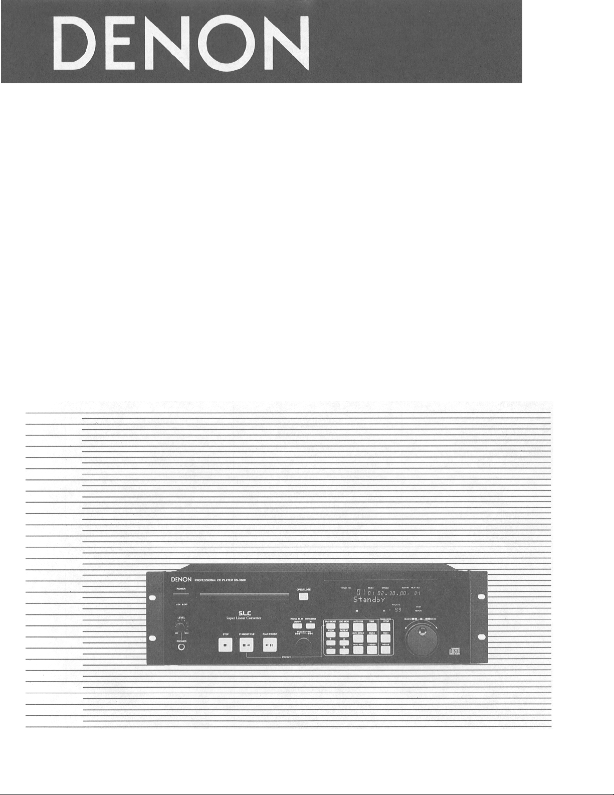
CD PLAYER
DN-C680
OPERATING INSTRUCTIONS
Page 2
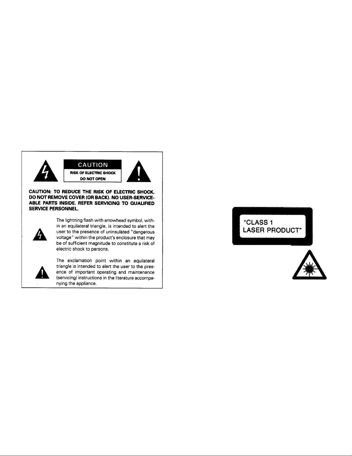
CAUTION
LABELS
A
IMPORTANT TO SAFE TY
WARNING:
TO PREVENT FIRE OR SHOCK HAZARD, DO NOT EXPOSE THIS
APPLIANCE TO RAIN OR MOISTURE.
:
1. Handle the power supply cord carefully
Do not damage or deform th e power supply cor d. If it is damaged or deform e d,
it may cause electric shock or malfunction when used. When removing from
wall outlet, be sure to remove by holding the pl ug attachment an d no t by pul l i ng th e c ord.
2. Do not open the top cover
In order to prevent electric shock, do not open the top cover.
If problems occur, contact your DENON dealer.
3. Do not place anything inside
Do not place metal objects or spill
Electric shock or malfunction may result.
Please, record and retain the Model name and serial number of your set shown on the rating label.
Model No. C-680 Serial No.
liquid inside the CD player.
(for U.S.A. model only)
CERTIFICATION
THIS PRODUCT COMPLIES WITH DHHS RULES 21 CFR SUBCHAPTER J
PPLICABLE AT DATE OF MANUFACTURE.
CAUTION: USE OF CONTROLS OR ADJUSTMENTS OR REFORMANCE OF PROCEDURES
OTHER THAN THOSE SPECIFIED HEREIN MAY RESULT IN HAZARDOUS RADIATION
EXPOSURE.
THE COMPACT DISC PLAYER SHOULD NOT BE ADJUSTED OR REPAIRED BY ANYONE
EXCEPT PROPERLY QUALIFIED SERVICE PERSONNEL.
NOTE:
This unit may c aus e i nter fer enc e to r adi o a nd t elev is ion r ece ptio n if you do not o per ate
it in strict accordance with this OPERATING INSTRUCTIONS.
This unit complies with Class B computing device rules in accordance with the
specificati ons in Sub-part J or Part 1 5 o f t h e FCC Rules, w hi c h are desig n ed to provide
reasonable pr otection agai nst such int erference i n a residential i nstallation. I f the unit
does cause i nterfere nce to a ny radi o or telev ision r ecepti on, try t o reduc e it by one or
more of the following me ans:
a) Turn the other unit to improve reception
b) Move this unit
c) Move this unit a way from others
d) Plug this unit respectively into a different AC outlet
NOTE:
This CD player uses the semiconductor laser. To allow you to enjoy music at a
stable operation, it is recommended to use this in a room of 5°C (41 °F) - 35°C (95°F).
• This is note to accordance with Section 15.838 of the FCC Rules.
CLASS 1
LASER PRODUCT
2
Page 3
SAFETY INSTRUCTIONS
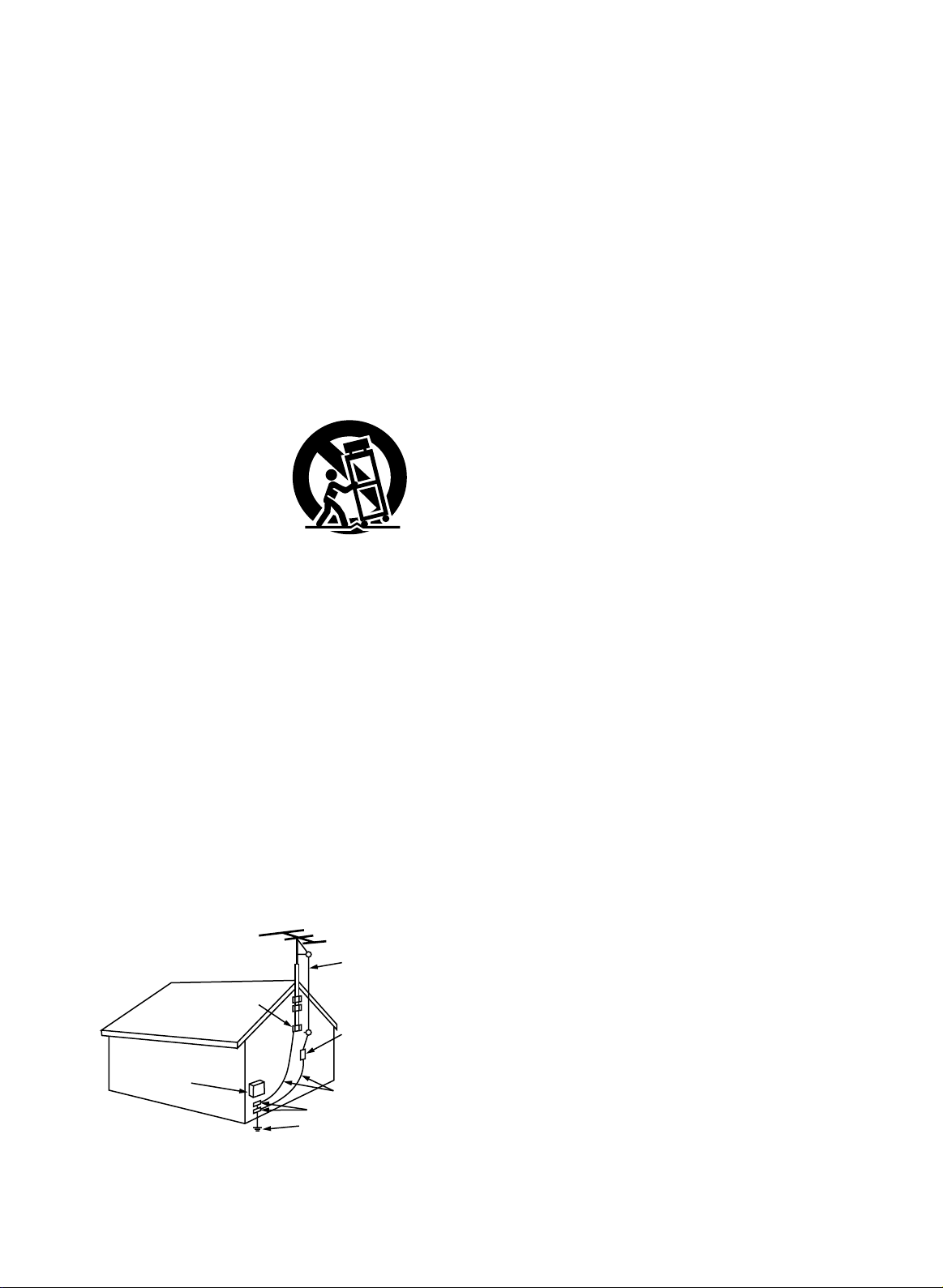
FIGURE A
EXAMPLE OF ANTENNA GROUNDING
AS PER NATIONAL
ELECTRICAL CODE
ANTENNA
LEAD IN
WIRE
GROUND
CLAMP
ELECTRIC
SERVICE
EQUIPMENT
ANTENNA
DISCHARGE UNIT
(NEC SECTION 810-20)
GROUNDING CONDUCTORS
(NEC SECTION 810-21)
GROUND CLAMPS
POWER SERVICE GROUNDING
ELECTRODE SYSTEM
(NEC ART 250, PART H)
NEC - NATIONAL ELECTRICAL CODE
1. Read Instructions – All the safety and operating
instructions should be read before the applicance is
operated.
2. Retain Instructions – The safety and operating instructions
should be retained for future reference.
3. Heed Warning – All warnings on the applicance and in the
operating instructions should be adhered to.
4. Following Instructions – All opeerating and use instructions
should be followed.
5. Water and Moisture – The appliance should not be used
near water – for example, near a bathtub, washbbowl,
kitchen sink, laundry tub, in a wet basement, or near a
swimming pool, and the like.
6. Carts and Stands – The appliance should be used only with
a cart or stand that is recommended by the manufacturer.
6A. An appliance and cart
combination should be
moved with care.
Quick stops, excessive
force, and uneven
surfaces may cause
the applicance and cart
combination to overturn.
7. Wall or Ceiling Mounting – The appliance should be
mounted to a wall or ceiling only as recommended by the
manufacturer.
8. Ventilation – The appliance should be situated so that its
location or position does not interfere with its proper
ventilation. For example, the appliance should not be
situated on a bed, sofa, rug, or similar surface that may
block the ventilation openings; or, placed in a built-in
installation, such as a bookcase or cabinet that may
impede the flow of air through the ventilation openings.
9. Heat – The appliance should be situated away from heat
sources such as radiators, heat registers, stoves, or other
appliances (including amplifiers) that produce heat.
10. Power Sources – The appliance should be connected to a
power supply only of the type described in the operating
instructions or as marked on the appliance.
11. Grounding or Polarization – Precautions should be taken so
that the grounding or polarization means of an appliance is
not defeated.
12. Power-Cord Protection – Power-supply cords should be
routed so that they are not likely to be walked on or
pinched by items placed upon or against them, paying
particular attention to cords at plugs, convenience
receptacles, and the point where they exit from the
appliance.
14. Cleaning – The appliance should be cleaned only as
recommended by the manufacturer.
15. Power Lines – An outdoor antenna should be located away
from power lines.
16. Outdoor Antenna Grounding – If an outside antenna is
connected to the receiver, be sure the antenna system is
grounded so as to provide some protection against voltage
surges and built-up static charges. Article 810 of the
National Electrical Code, ANSI/NFPA 70, provides
information with regard to proper grounding of the mast
and supporting structure, grounding of the lead-in wire to
an antenna-discharge unit, size of grounding conductors,
location of antenna-discharge unit, connection to grounding
electrodes, and requirements for the grounding electrode.
See Figure A.
17. Nonuse Periods – The power cord of the appliance should
be unplugged from the outlet when left unused for a long
period of time.
18. Object and Liquid Entry – Care should be taken so that
objects do not fall and liquids are not spilled into the
enclosure through openings.
19. Damage Requiring Service – The appliance should be
serviced by qualified service personnel when:
A. The power-supply cord or the plug has been damaged;
or
B. Objects have fallen, or liquid has been spilled into the
appliance; or
C. The appliance has been exposed to rain; or
D. The appliance does not appear to operate normally or
exhibits a marked change in performance; or
E. The appliance has been dropped, or the enclosure
damaged.
20. Servicing – The user should not attempt to service the
appliance beyond that described in the operating
instructions. All other servicing should be referred to
qualified service personnel.
3
Page 4
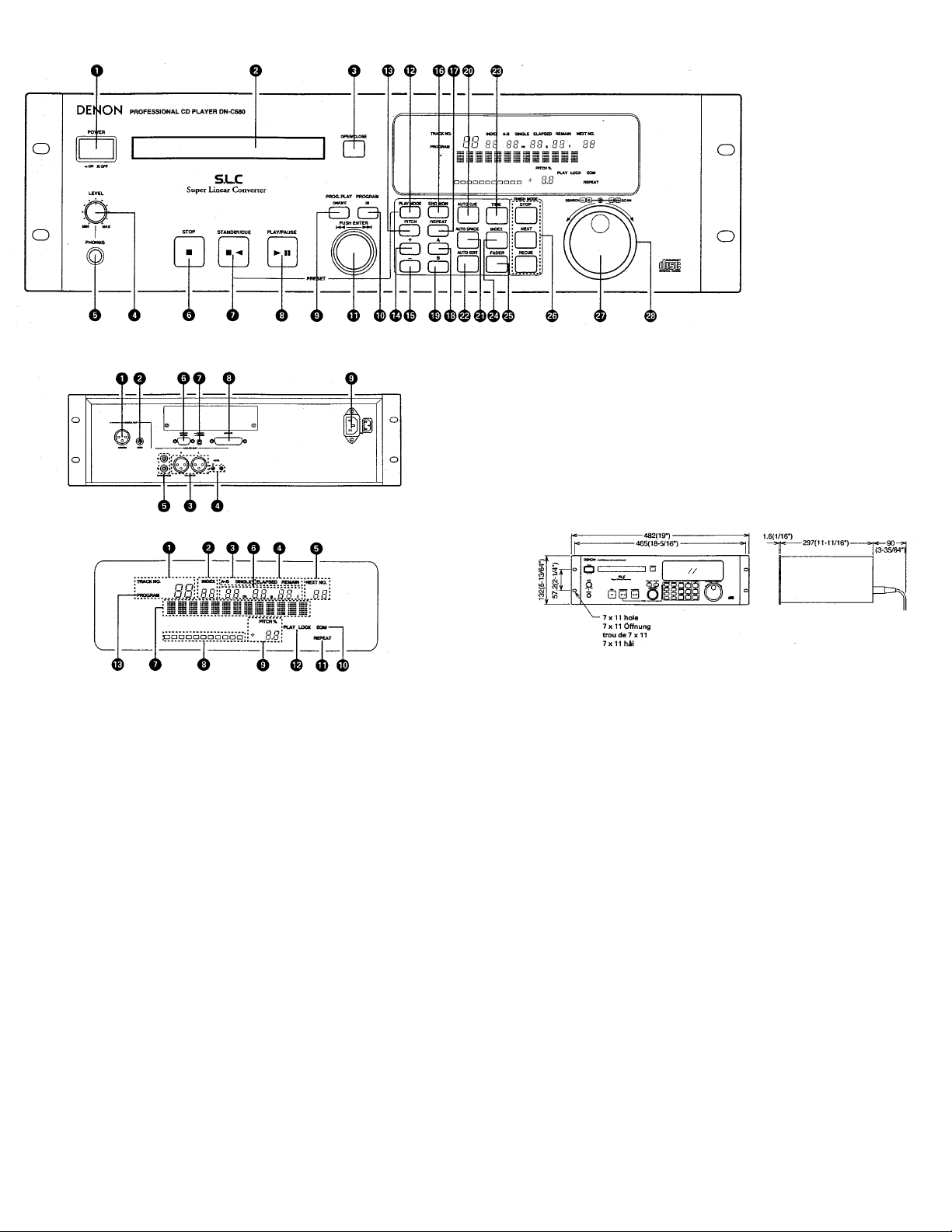
FRONT PANEL
L
DISPLAY WINDOW
REAR PANE
DIMENSIONS
4
5
Page 5
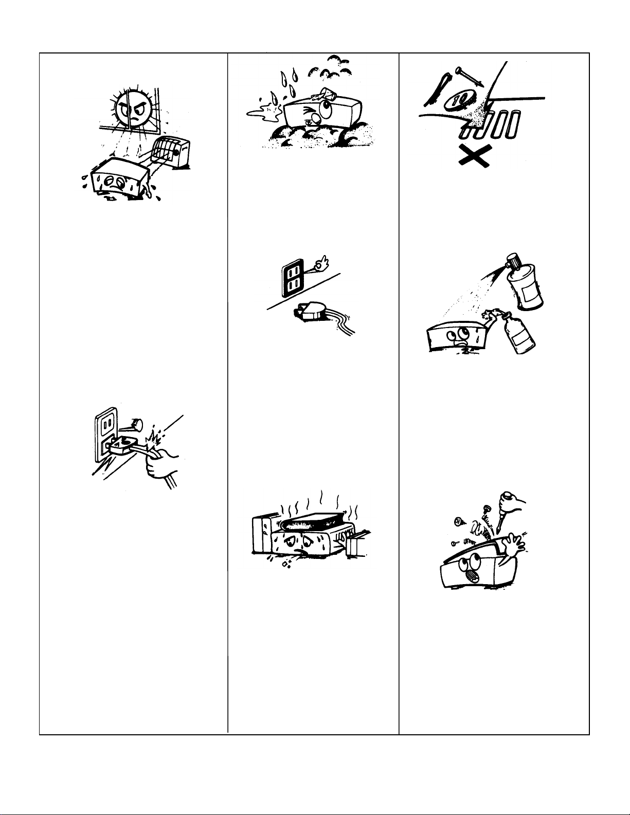
NOTE ON USE
A
Keep the set free from moisture,
water, and dust.
Do not let foreign objects in the set.
void high temperatures
Allow for sufficient heat dispersion
when installed on a rack.
Handle the power cord carefully. Hold
the plug when unplugging the cord.
Unplug the power cord when not
using the set for long periods of time.
"(For sets with ventilation holes)
Do not obstruct the ventilation holes.
Do not let insecticides, benzene, and
thinner come in contact with the set.
Never disassemble or modify the set
in any way.
6
Page 6

The DN-C680 CD player is a rack mount type CD player designed for use in broadcast stations, for production; etc.
• 19 inch Rack Mountable (Height 3U)
Large FL Display, Illuminated Rubber Button
•
•
Track Search Select knob (Easy track selection)
•
Jog/ Shuttle Wheel
Perform searches to 1 fra me precision using the jog dial and easy scans using the shuttle ring.
•
Program Play (Max. 25 tracks)
(1) When the PLAY mode is set to Single, the player stands by at the beginning of next track. (at Finish mode Next)
(2) When the PLAY mode is set to Continuous, the playback is continued according to your programmed sequence.
•
Play mode and Finish mode
(1) Play mode
MAIN FEATURES
cContinuous: Play a whole disc
dSingle: Play a trac k
e A-B: Play a A-B
(2) Finish mode (Stop, Next, Recue)
* only when Single Track play is selected.
cStop: Stop after finishing to play a track.
dNext: Standby at the beginning of next track after finishing to play track.
eRecue: After finishing to play a track, standby at the beginning of the track.
Auto Cue
•
After a disc is load ed, it is automatically cued to the point where audio starts. Cueing takes place at the point where a udio starts rather than where the track
starts. The level at which sound is first detected can be set between -36 to -72dB (7 steps).
•
End Monitor
Pressing the END MON button during standby instantly previews the end of the track, thus assuring perfect "end point". The point at which monitoring starts can
be set within a range of 5 to 35 seconds (7 steps) prior to the track's end.
•
End of Message (EOM)
At the end of a track, the Display's EOM button flashes, providing a visual warning to the operator that the track will end shor tly. The poin t at wh ic h the flashing
begins can be set within a range of 0 to 30 seconds (7 steps) prior to the end of the track.
•
Pitch Control (t 9.9%, 0.1 % step) e Index Search
The Select knob can be used to perform an Index Search when the INDEX button is ON. (The LED on the INDEX button light up.)
•
AUTO SPACE
During playback, it is possible to insert a silent space of about 4 seconds between tracks. To do this, simply press the AUTO SPACE button to ON.
(The LED on the AUTO SPACE button light up.)
•
AUTO EDIT
This function automatically divides the total recorded time on the disc in half and re arranges the trac k so that they fit nearly onto the A and B sides.
•
Display of Playback Locations
A bar graph display indicates playback points on the track being played. Elapsed time and Remaining time displays are switched using the TIME button.
•
Rich Array of External Control Terminals
Serial Remote (RS232C/RS422A switchable, D-su b 9 pin) Parallel Remote (D-sub 25 pin)
•
ACD-25FSC (FS Converter Kit) Option
Digital output is possible at 32 and 48 kHz a s well as 44.1 kHz. Output frequency can be preset to 32, 44.1, or 48 kHz.
7
Page 7
p
)
CONTENTS
1. PART NAMES AND FUNCTIONS .................................................9~11
(1) Front Panel .......................................................................... 9,10
(2) Rear Panel ......................................................................... 10,11
(3) Display ................................................................................... 11
2. REMOTE CONTROL CONNECTION...................................................12
3. OPENING AND CLOSING THE DISC HOLDER AND
LOADING DISCS ...........................................................................12
4. BASIC OPERATIO N ................................................................. 13, 14
(1) Before Starting Playback ...........................................................13
(2) Starting Playback .....................................................................14
(3) Stopping Playback ................................................................... 14
(4) PLAY/P AUS E and STANDBY/CUE Operations............................... 14
5. HANDY OPERATIONS ............................................................... 15-18
(1) Starting Playback from the Middle of a Track
(Manual Search) .......................................................................15
(2) Playing at a. Different Speed (Pitch) ..........................................15
(3) Playing a Specific Section of the Disc (A-B Play) ..........................16
(4) Playing Repeatedly (Repeat) .....................................................17
(5) Inserting Blank Spaces Between Tracks (Auto Space) .................. 18
(6) Dividing the Pla ying Time in Two (Auto Edit) ..............................18
Checking the Contents
Check that the carton contains the following items:
3P power supply cord 1 PC.
erating instructions (this booklet
O
1 PC.
6. PROGRAMMED PLAYBACK ........................................................ 19~21
(1) Inputting the Program ............................................................ 19
(2) Changing the Program ........................................................19, 20
(3) Playing Programs ................................................................... 20
(4) Presetting Programs ................................................................ 21
7. PRESET FUNCTIONS AND OPERATIONS .................................. 22~25
(1) List of Preset Functions ........................................................... 22
(2) Presetting Procedure ...............................................................23
(3) Detailed Description of Preset Functions .............................. 24, 25
8. BEFORE SWITCHING OFF THE POWER .......................................... 26
9. COMPACT DISCS ......................................................................... 26
10.
TROUBLESHOOTING ..................................................................... 27
11. SPECIFICATIONS ..........................................................................27
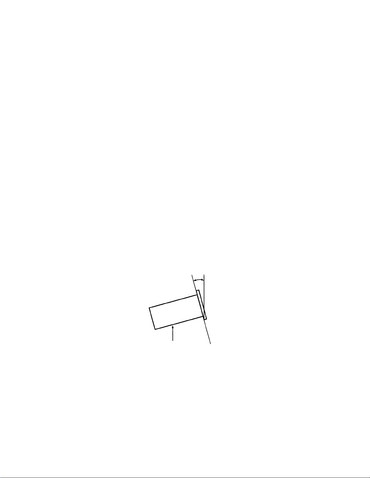
Installing the Units
Mount the units onto your console or rack with 19" EIA rack rails.
CAUTION:
• The DN-C680 will work normally when the player unit is mounted with the front panel within 15 degrees of the vertical plane. If the unit is tilted
excessively, discs may not load or unload properly.
Max. 15°
DN-C580
• DECLARATION OF CONFORMITY
We declare under our sole responsibility that this product, to which this declaration relates, is in conformity with
the following standards: EN60065, EN55013, EN55020, EN60555-2 and EN60555-3. Following the provisions of
73/23/EEC, 89/336/EEC and 93/68/EEC Directive.
8
Page 8

PART NAMES AND FUNCTIONS
(1) Front Panel
POWER button
•
This turns the set on and off.
Disc holder
•
Place discs in this holder.
Press the OPEN/CLOSE button to open and close the disc holder.
Load discs firmly inside the slot.
OPEN/ CLOSE button
•
Press this button to open and close the disc hold er. The
disc holder will not open during playback.
LEVEL control
Use this to adjust the volume of the headphones .
•
PHONES jack
•
Connect headphones with an imp eda nce of 30 to 40 62/ohms.
STOP button
Press this button to turn all the servo functions off and stop. Press
•
this button during playback to set the stop mode.
STANBDY / CUE button
When this button is pressed during the play or pause mode, the
•
pickup returns to the position at which play back started and the
standby mode is set. (Back Cue)
• When pressed during playback when the next track has been
programmed, the programmed track is searched for and the
standby mode is set.
• The button lights when the standby mode is set.
• When the button is pressed while pressing the PLAY MODE button,
the preset mode is set.
PLAY / PAUSE button
Press this button in the standby, pause or manual search mode to
•
begin playback.
• Press the button in t he stop mo de to search for the first tr ack and
begin playback.
• The button lights during the play mode.
• When the button is pressed during playback, the pause mode is set.
The button flashes while the pause mode is set.
PROG. PLAY ON/ OFF button
•
When this button is p ressed while the PROGRAM I N button is lit,
the program play mode is set.
• The button will not function during the A-B play mode.
• The button lights during the program play standby and play modes.
• When the button is pressed during the program play standby or
play mode, the program play mode is cleared.
PROGRAM IN button
Press this button to set the program input mode.
•
• The button will not function during the play mode.
• The button flashes when in the program input mode.
• The button lights when a program is set.
Select knob
Turn this' kno b to select the ne xt track (or index number) to be
•
played.
• Use the INDEX bu tton to c hoose whe ther to se lect track s or index
numbers.
• Turn the knob clockwise by one click to move one track (or one
index number) fo rward, c ounter clockwi se by one click to m ove o ne
track (or one index nu mber) backward.
• When the knob turned while pressing it in, one click corresponds to
10 tracks (or 10 index numbers).
• In the preset mod e, use this knob to set and ent er preset settings.
• When setting pro grams, use this knob to select, enter and c heck
the program.
PLAY MODE button
•
Press this button to switch the play mode.
PITCH button
•
Press this butto n to switch to the pla y speed set with the + a nd
-buttons.
• The button lights when the pitch play mode is set.
• Press the button again to cancel the pitch pl ay mode and return to
the normal speed.
+ button
Press this button once to increase the pitch by 0.1 %.
•
• Hold the button in to increase the pitch contin uously.
• Press the button in the program e diting mode to set the program
insert mode.
- button
Press this button once to decrease the pitch by 0.1%.
•
• Hold the button in to decrease the pitch continuously.
• Press the butt on in the program editing mode to clear the program.
END MON button
•
Press this button in the standby mode to monitor the end of the
track. (End Monitor)
• The button lights when the end monitor mode is set.
REPEAT button
•
Press this button to set the repeat mode.
• The button lights when the repeat mode is set.
• Press the button again to cancel the repeat mode.
A button
•
Press this button when no A point is set to set the A point.
• The button lights when the A point is set.
• When pressed while the A point is set, the A point is searched for
and the standby mode is set.
• When the button is pressed during m anual searc h while the A poi nt
is set, the A point changes.
B button
•
Press this button when no B point is set to set the B point.
• The button lights when the B point is set.
• When pressed while the B point is set, the B point is searched for
and the standby mode is set.
• When the button is pressed during manual search while the B point
is set, the B point changes.
9
Page 9

A
UTO CUE button
• Press this button to find the begi nning o f the pl ayback s ignal s on a
track and automatically set the standby mode at that point. (Auto
Cue)
• The button lights when the auto cue mode is set.
• Press the butt on again to cancel the auto cue mode.
AUTO SPACE button
• Press this button to automatically insert blank spaces of 4 seconds
between tracks during continuous playback. (Auto Space)
• The button lights when the auto space mode is set.
• Press the butt on again to cancel the auto cue mode.
AUTO EDIT button
• Press this button to divide the tracks on the dis c into a first half
(side A) and seco nd half (s ide B) at the point ne arest to half o f the
disc's total playing time. (Auto Edit)
• When the A button is pressed while the auto edit mode is on, the A
button lights and the number of the first track and total playing
time of the first half (side A) are displayed on the character display.
• When the B button is pressed while the auto edit mode is on, the B
button lights and the number of the first track and total playing
time of the second half (side B) are displayed on the character
display.
• Press the button again to cancel the auto edit mode.
TIME button
• Press this butto n to switc h the time display between the rema ining
time (REMAIN) and the elapsed time (ELAPSED).
INDEX button
• Press this button to s et the index s elect mode, then use the sele ct
knob to select the index number.
• The button lights when the index select mode is set.
• Press the button again to return to the track select mode.
FADER button
• Press this button to enable input of the fader input signals
connected to the "PARALLEL REMOTE" connector.
• The button lights when fader input signal input is enabled.
• Press the button again to cancel the mode.
FINISH MODE button
One of the following three finish modes can be selected:
• Press the STOP button to light the button and set the finish mode to
the stop mode.
• Press the NEXT butto n to light the butto n and s e t the f inish mode to
the next mode.
• Press the RECUE but ton to light the button and set the finis h mode
to the recue mode.
SEARCH dial (inner side)
• Turn this dial to set the manual search mode.
• Turn the dial clockwise to move the playback position forward,
counterclockwise to move the playback position backward.
• One click corresponds to one frame of movement. The playback
position can be moved anywhere betwee n the beginning o f the first
track and the end of the last track.
SCAN dial (outer side)
• Turn this dial to set the m an ual s earc h (fast fo rwar d or fast re ver se)
mode.
• Turn the dial clockwise to move the playback position forward,
counterclockwise to move the playback position backward.
• The speed changes according to the angle at which the dial is turned.
Rear Panel
DIGITAL OUT (BALANCED) connector
• This is an active balanced output using an XLR type connector.
• Connect this conne cto r to the bala nce d d igita l inp ut co nne cto r on an
amplifier or console.
• Signal format: Selectable (See Page 24, 8) 9))
• Pin layout: 1. Common
2. Cold
3. Hot
• Applicable connector: Cannon XLR-3-31 or equivalent
DIGITAL OUT (UNBALANCED) jack
• This is an unbalanced output using an RCA type jack.
• Connect this jack to the unbalanced digital input jack on an
amplifier or console.
• Signal format: Selectable (See Page 24, 8) 9))
ANALOG OUT (BALANCE) connectors
• These are active balanced outputs using XLR type connectors.
• Connect these connectors to the balanced analog input connectors
on an amplifier or console.
• Pin layout:
Pin No. U.S.A. & Canada Europe & Asia & Others
1
Common Common
2 Cold Hot
3 Hot Cold
• Applicable connector: Cannon XLR-3-31 or equivalent
NOTE: Do not short-circuit the hot or cold pin with the common pin.
LEVEL L/R controls
• Use these controls to adjust the level of the audio-signals from the
ANALOG OUT (BALANCED) connectors.
ANALOG OUT (UNBALANCED) jacks
• These are unbalanced outputs using RCA type jacks.
• Connect these jacks to the unbalanced analog input jacks on an
amplifier or console.
10
Page 10

A
RS232C/RS422A connector
• This is a serial remote connector. A personal computer or other
external controller can be connected to control the DN-C680
externally.
• Applicable conn ector: 9-pin D-sub (female)
• Baud rate: 9600 bps or 19200 bps
• Pin layout:
RS232C RS422A
Pin no. Signal name I/0 Signal name I/0
1 NC - NC -
6 NC - S.GROUND -
2 TxD 0 TxD (RETURN) 0
7 NC - TxD 0
3 RxD I RxD I
8 NC - R x D (RETURN) I
4 NC - NC -
9 NC - NC -
5 S.GROUND - S.GROUND -
RS232C /RS422A selector switch
Use this to switch the serial remote connector signal between
RS232C and RS422A according to the external controller's signal.
REMOTE connector
This is a parallel remote connector. Use it to control the DN-C680
with dry contact circuit connections. Applicable connector: 25-pin
D-sub (male) Connector signal layout:
Pin no. Signal name I/O
1 FG -
14 2 PLAY tally
PLAY command
15 PAUSE tally O TTL(lol=20mA)
3 PAUSE command I HCMOS(li=3mA)
16 STDBY/CUE tally O TTL(lol=20mA)
4 STDBY/CUE command I HCMOS(li=3mA)
17 INDEX2/INDEX3 tally O TTL(lol=20mA)
5 TRACK(+) command I HCMOS(li=3mA)
18 Tally common -
6 TRACK(-) command I HCMOS(li=3mA)
19 Reserved -
7 SEARCH(FWD) command I HCMOS(li=3mA)
20 Reserved -
8 SEARCH(REV) command I HCMOS(li=3mA)
21 Reserved -
9 FADER START command I PHOTO COUPLER
22 Tally power supply - +5V, 20mA
10 Command common - (Ii =10mA)
23 Command common -
11 NC -
24 EOM tally O TTL(lol=20mA)
12 Reserved -
25 Reserved -
13 Reserved -
NOTE: The tally output pin has open collector IC specifications (Imax. 20
mA, Vmax. 5V), but the maximum supply current is 80 mA, so use
with a total load current of 80 mA or less.
O I TTL(lol=20mA)
HCMOS(li=3mA)
(3) Display
TRACK No. display
This indicate s the track num ber at the cur rent position. The track
•
number flashes during the track search operation and when
switching to the standby mode.
INDEX No. display
This indicates the index numb er at the current pos ition. If the next
•
index is scheduled, that index number flashes on the INDEX No.
display. The index number also flashes during the index search
operation.
PLAY MODE indicators
"A-B" lights when in the A-B play mode.
•
• "SINGLE" lights when in the single track play mode.
TIME MODE indicators
"ELAPSED" lights when the elapsed time is displayed.
•
• "REMAIN" lights when the remaining time is displayed.
NEXT No. display
•
This displays the number of the next track to be played.
Playing time display
This indicates the time of the current position, in minutes (m),
•
seconds (s) and frames (f).
Character display
This displays operation messages in the preset and program
modes.
Playing position display
This indicates t he current position within t he track's total playing
•
time.
PITCH display
This indicates the set play speed in %.
•
EOM indicator
This lights when the EOM is preset, and starts flashing when the
•
EOM set time is reached.
REPEAT indicator
This lights when the repeat mode is set.
•
PLAY LOCK indicator
This lights when th e PLAY LOCK is preset.
•
(See Page 25,17))
PROGRAM indicator
This lights when the PROG. PLAY ON/OFF mode is set.
•
C inlet
•
Connect the included power cord here.
11
Page 11

r
REMOTE CONTROL CONNECTIONS
To control the DN-C680 remotely, ref er to the example of remote control connections given below.
The rating of REMOTE connector pin 22 (TALLY POWER SUPPLY) is +5 V, 80 mA maximum.
Avoid currents in excess of the rating.
OPENING AND CLOSING THE DISC HOLDER AND LOADING DISCS
(1) Opening and closing the disc holde
• This operation only works when the power is on.
• Press the OPEN /CLOSE button to open or close the disc holder.
• The disc holders cannot be opened during playback to prevent playback from being interrupted if the OPEN/CLOSE button is pressed accidentally.
Stop playback, then press the OPEN/CLOSE button.
(2) Loading discs
•
• When using 12cm discs, place the disc in the outer tray guides, and when using 8cm discs, place them securely in the inner guides.
CAUTION:
• Do not place any foreign objects in the disc tray, and do not place more than one disc in the disc tray at a time. Doing so may result in malfunction.
• Do not push the disc tray in manually when the power is off, as this may result in malfunction and damage the player.
Hold the disc by the edges and place it in the disc tray, Do not touch the signal surface (the glossy side).
12
Page 12

BASIC OPERATION
13
Page 13

g
(4) PLAY /PAUSE and STANDBY/ CUE Operations
• The operation switches between playback and pause each time
the PLAY/PAUSE button is pressed.
• When the STANDBY/CUE button is pressed during playback, the
pickup returns to the position at which playback was started.
The diagrams below show playback patterns when the PLAY/PAUSE
and STANDBY/CUE buttons are pressed.
(2) Starting Playback
(3) Stoppin
Playback
When the PLAY/PAUSE button is pressed, playback starts and proceeds as
shown b y the arrow on the diagram ab ove.
If the PLAY/PAUSE button is pressed again during playback, the pause
mode is set at that point. Press the PLAY/PAUSE button again to resume
playback.
When the STANDBY/CUE button is pressed after starting playback by
pressing the PLAY/PAUSE button, the pickup returns to the position at
which playback was started and prepares for the next playback.
Press the PLAY/PAUSE and STANDBY/ CUE buttons alternately to start
playback repeatedly from the same position.
This function is called "Back Cue".
Sleep mode
The sleep mode is set if no operation is performed for 30 minutes in the standby, pause or manual search mode.
When in the sleep mode, press the PLAY/PAUSE button to search
for the position before the sleep mode was set and start
playback. Press the STANDBY/CUE button to search for the
position before the sleep mode was set and standby at that point.
14
If the pause mode is set and playback is then resumed, the position to
which the pickup returns with the Back Cue function changes.
Page 14

g
g
HANDY OPERATIONS
(1) Starting Playback from the Middle of a Track (Manual
Search)
• When a track is selected and the PLAY/PAUSE button is pressed,
playback starts from the beginning of that track. To start from a
different position in the track, use the procedure described below
to find the desired position.
(2) Playin
• Use this function to play discs at different speeds.
• The speed can be changed within the range of -9.9 to +9.9%.
at a Different Speed (Pitch)
NOTE:
When the play speed (PITCH) is set, the display shows the set
pitch, but the disc is played at the standard speed until the
PITCH button is pressed (and the button is lit). When the play
speed is changed, the sampling frequency of the digital output
signal also changes, so it may not be possible to receive digital
nals.
si
15
Page 15

g
(3) Playin
• Use this function to set the play start and end positions and only
NOTE: The A-B play mode cannot be set unless the A point, B point
or both the A and B points are set.
a Specific Section of the Disc (A-B Play)
play the desired section of the disc.
NOTE:
The following happens if either the A or B point is not set:
• If only the A point is set, the B point is automatically set at
the end of the track for which the A point is set.
• If only the B point is set, the A point is automatically set at
the beginning of the track for which the B point is set.
If the playing time of the A-B section is shorter than the total
of the set fade in and fade out times, the fade in and fade out
settings are ignored.
When the B point is before the A point, the section from the B
point to the A point is played.
16
Page 16

A
g
(4) Playin
Repeatedly (Repeat)
-B repeat play
17
Page 17

g
g
(
(5) Inserting Blank Spaces Between Tracks (Auto Space)
• Use this function to insert blank spaces of 4 seconds between
tracks durin
continuous playback.
(6) Dividin
the Playing Time in Two (Auto Edit)
• Use this function to divide the total playing time of the disc into
first half) and side B (second half).
side A
NOTE:
When non-consecutive tracks are played (when the search operation is performed), a blank space of over 4 seconds may be
inserted automatically.
18
Page 18

(2)
ging
PROGRAMMED PLAYBACK
• The tracks can be programmed to play in a certain order.
• Up to 25 tracks can be programmed.
• Programmed playback is performed according to the play mode
(single or continuous) and finish mode (stop, next or recue) settings.
Chan
the Program
To exit the program editing mode, press the PROGRAM IN button. The set returns to the normal mode.
19
Page 19

(3)
Playing Programs
20
Page 20

(4) Presetting Programs
• Programs can be stored in the preset memory. When a disc for which a program is preset is loaded, the programmed playback mode is set
automatically.
• Programs can be stored for up to three discs.
21
Page 21

PRESET FUNCTIONS AND OPERATIONS
(1) List of Preset Functions
• Functions can be preset using the buttons on the front panel. These presettings are stored in a permanent memory, so they are not cleared even
when the power is turned off.
• The functions shown on the table below can be preset. Set the functions according to the usage purpose to efficiently achieve even higher quality
playback.
• One of the preset functions can be used to display information on this set (microprocessor version).
Preset function type Description Character display
Preset type Selection of preset type Preset Type 1 1
Auto cue Setting of audio startup level for auto cue function CueDet.-60db 2
Auto stop Setting of whether or not to automatically stop the servo functions Sleep ON 3
FS converter Setting of whether or not to use the FS converter and sampling frequency
setting (when optional FS converter mounted)
Progr a m 1 Setting of whether or not to pla y program 1 Program1 OFF 5
Progr a m 2 Setting of whether or not to pla y program 2 Program2 OFF 6
Progr a m 3 Setting of whether or not to pla y program 3 Program3 OFF 7
Digital output Selection of output signal format D.Out Pro 8
Digital output Selection of whether or not to output subcodes Subcode OFF 9
End monitor Setting of whether or not to use the end monitor function and monitor
time setting
E.O.M. Setting of whether or not to display the EOM and display time setting E.O.M. 10sec 11
Next track standby Setting of whether or not to standby at the next track when the
STANDBY/CUE button is presse d during playback
Fade in time Fade in time setting Fadeln OFF 13
Fade out time Fade out time setting Fadeout OFF 14
Play speed Standard playing speed setting Normal Speed 15
Delay start Delay start time setting Delay OFF 16
Play lock Selection of whether or not to inhibit the panel switches during playback PlayLock OFF 17
Frame display Selection of whether or not to display frames FR Disp ON 18
CDR disc Selection of whether or not to play CDR discs which do not include a TOC CD-R NO TOC 19
CDR disc Selection of whether or not to play skip tracks on CDR discs CD-R Skip OFF 20
Serial remote Baud rate setting 9600bps 21
Switch protect Selection of whether or not to enable the panel switches Switch ENA 22
Player ID Selection of whether or not to set player IDs and selection of ID number PlayerlD OFF 23
Parallel remote Selection of whether or not to accept parallel remote signals Remote ENA 24
Parallel remote Selection of whether or not to output standby tally ST. Tally ON 25
Parallel remote External control tally output signal setting Index2 Tally 26
Parallel remote Fader start mode selection Fader Pause 27
Stereo/mono Selection of stereo or monaural playback Stereo 28
Pos Code Selection of whether or read Pos codes Pos OFF 29
Preset clear Setting for clearing presets and setting them to the initial values ' Init. Preset 30
Set information Microprocessor version display
(as set upon shipment from
factory)
FS OFF 4
End Mon. 10sec 10
NextStb.OFF 12
Ver. **** (* = number)
No.
31
When presettings are made, the time display set with the TIME button, the play mode set with the PLAY MODE button and the finish mode set with the
FINISH MODE button at that time are stored in the memory. These modes will be set when the power is next turned on.
NOTE:
For CDR discs without TOCs, there are no pits (signals) at the disc's lead in and lead out sections, so errors may occur, particularly when searching
for tracks. If an error should occur, open the disc holder, then close it and perform the operation again.
22
Page 22

(2) Presetting Procedure
• Functions can be preset using the buttons on the front panel.
• Th e presettings can also be set using serial remote signals (RS232C/RS422A1.
• Make the presettings with no disc loaded, in th e stop or standby mode.
23
Page 23

(3) Detailed Description of Preset Functions
(* = initial setting)
1) "Preset Type (*1" (Three different sets (types) of presettings can be made and used for different purposes.)
* Preset Type1 : Set to preset type 1.
Preset Type2 : Set to preset type 2.
Preset Type3 : Set to preset type 3.
2) "CueDet. (-**) dB"
CueDet. (-**) dB : Set th e audio detection level for cueing. (-72/-66/*-60/-54/-48/-42/-36)
3) "Sleep ON (OFF)"
* Sleep ON : Automatically turn the servo functions off if no button is operated for 30 minutes in the pause, standby or manual
search mode.
Sleep OFF : Do not automatically turn the servo functions off.
4) "FS OFF (***kHz)" (This setting can only be made when an optional FS converter is mounted.)
* FS OFF : Do not use the FS converter.
FS (***kHz) : Select the digital output FS. (32kHz/44.1 kHz/48kHz)
5) "Programl OFF (ON)"
Programl OFF (ON) : Store the contents of program 1 when on. (Initial setting-OFF)
6) "Progam2 OFF (ON)"
Program2 OFF (ON) : Store the contents of program 2 when on. (Initial setting - OFF)
7) "Program3 OFF (ON)"
Program3 OFF (ON) : Store the contents of program 3 when on. (Initial setting - OFF)
8) "D.Out Pro (Cons)"
*D.Out Pro : Output digital signals in AES/EBU format.
D.Out Cons : Output digital signals in consumer format.
9) "Subcode ON (OFF)" (When "D.Out Cons" is set above, subcodes can be output with the digital output signals.)
Subcode ON : Output subcodes with the digital output signals. (consumer SPDIF format)
*Subcode OFF : Do not output subcodes with the digital output signals. (consumer IEC 958 Type II format)
NOTE: 0 sec. start is not possible when the above is set to "Subcode ON".
10) "End Mon. (**)sec"
End Mon. (**)sec : Set the end monitor time. (5/*10/15/20/25/30/35)
End Mon. OFF : Do not use the end monitor function.
11) "E.O.M. (**)sec" (Output EOM tally signal to remote pint (24))
E.O.M. (**)sec : Set the EOM time. (0/5/*10/15/20/25/30)
E.O.M. OFF . Do not use the EOM function.
12) "Next Stb.Off (ON)"
*Next Stb.OFF : Return to the play start position and standby when the STANDBY/CUE button is pressed during playback.
Next Stb.ON : Standby at the beginning of the next track when the STANDBY/CUE button is pressed during playback.
13) "FadeIn OFF ('s)"
Fadeln OFF (***s) : Set the fade in time. (*OFF/10m/50m/0.1/0.5/1/2)
14) "FadeOut OFF (***s)"
FadeOut OFF (***s) : Set the fade out time. (*OFF/10m/50m/0.1/0.5/1/2)
15) "Normal (+/-***%) Speed"
*Normal Speed : Play at normal speed.
(+/-***%) Speed : Play at variable speed. t(0.2/0.4/0.6/0.8/1.0/1.2/1.4/1.6/1.8/2.0/2.2/2.4/2.6/2.8/3.0)
24
Page 24

16) "Delay OFF (***ms)"
Delay OFF (***ms) : Set the time for delayed start after the play start operation. (*OFF/100m/200m/300m)
17) "PIayLock ON (OFF)"
PIayLock ON : Inhibit all operations other than the PLAY/ PAUSE, TIME and PLAY MODE buttons during playback.
* PIayLock OFF : Enable all functions during playback.
18) "FR Disp ON (OFF)"
* FR Disp ON : D isplay the frames on the time display during playback.
FR Disp OFF : Do not display the frames on the time display during playback.
(The frames are displayed in the manual search, standby, pause and end monitor modes.)
19) "CD-R TOC (NO TOC)"
CD-R TOC . : Play normal CDR discs containing TOCs.
* CD-R NO TOC . : Play CDR discs not containing TOCs.
20) "CD-R SkipON (OFF)"
CD-R SkipON . : Play skip tracks on CDR discs.
* CD-R SkipOFF . : Do not play skip tracks on CDR discs.
21) "9600 (19200) bps"
* 9600 bps : Set t h e baud rate to 9600 bps.
19200 bps : Set the baud rate to 19200 bps.
22) "Switch ENA (INH)"
* Switch ENA : Enable operation of all the switches on the front panel.
Switch INH : Inhibit operation of all panel switches other than those used for presetting operations.
23) "Player ID (**1"
Player ID (**) : Set the player ID.
(The ID can be set to OFF or to 0 to 15. The initial setting is "OFF".)
24) "Remote EMA (INHI"
* Remote ENA : Enable input of control signals to the parallel remote connector.
Remote INH : Inhibit input of control signals to the parallel remote connector.
25) "St. Tally ON (OFF)"
* St. Tally ON : Output standby tally from parallel remote connector.
St. Tally OFF : Do not output standby tally from parallel remote connector.
26) "(******) Tally"
* INDEX2 Tally : Output index 2 tally signal to remote pin (17).
INDEX3 Tally : Output index 3 tally signal to remote pin (17).
27) "Fa der Pause (Play )"
* Fader Pause : Start playback when remote fader pins (9-10) are short-circuited and pause when pins are open.
Fader Play : Start playback when remote fader pins (9-10) are short-circuited and continue playback when pins are open.
28) "Stereo (Mono)"
* Stereo : Output L and R stereo signals from the output connector.
Mono : Output mixed L and R signals from the output connector.
29) "Pos ON (OFF)"
Pos ON : Read Pos codes on CD and CDR discs.
* Pos OFF : Do not read Pos codes on CD and CDR discs.
30) "Preset Clr? (Init. Preset)"
31) "Ver. xxxx" : Display the microprocessor version. ("xxxx" is a number.)
Preset Clr? : Clear the presettings (set to the initial factory values).
* Init. Preset : Do not clear the presettings.
25
Page 25

g
g
BEFORE SWITCHING OFF THE POWER
When you have finished using the CD player, before switching off the power be sure that the disc holder has been closed with the OPEN/CLOSE button.
CAUTION:
Do not forcibly close the disc holder when the power is off. It
may damage the unit when it is transported.
Do not switch off the power when the disc
holder is open.
POWER OFF
Switch off the power after the disc holder has
been closed with the OPEN/CLOSE button.
POWER OFF
COMPACT DISCS
(1) Precautions on handlin
• Do not allow fingerprints, oil or dust to get on the surface of the disc.
If the disc is dirty, wipe it off with a soft dry cloth.
• Do not use benzene, thinner, water, record spray, electrostatic-proof chemicals, or silicone-treated cloths to clean discs.
• Always handle discs carefully to prevent damaging the surface; in particular when removing a disc from its case or returning it.
• Do not bend the disc.
• Do not apply heat.
• Do not enlarge the hole in the center of the disc.
• Do not write on the label (printed side) with a hard-tipped implement such as a pencil or ball point pen.
• Condensation will form if a disc is brought into a warm area from a colder one, such as outdoors in winter. Do not attempt to dry the disc with a
hair dryer, etc.
(2) Precaution on stora
• After playing a disc, always unload it from the player.
• Always store the disc in the jewel case to protect from dirt or damage.
• Do not place discs in the followi ng areas:
1) Areas exposed to direct sunlight for a considerable time.
2) Areas subject to accumulation of dust or high humidity.
3) Areas affected by heat from indoor heaters, etc.
compact discs
e
26
Page 26

TROUBLESHOOTING
When you think the player might be broken, please check the following items.
The disc holder does not open or close.
• Is the power switch set to ON?
• Is the player in the process of playing a disc? . . . . . . . . . . . . . . . . . . . . . . . . . . . . . . . . . . . . . . . . . . . . . . . . . . . . . . . . . . . . . . . . . . See page 12
The display still indicates “—“ when a disc is loaded.
• Is the disc loaded properl y?
• Is the disc dirty or scratched?
There is no sound or the sound is distorted.
• Are the output cables connected to the amplifier correctly?
• Is the adjustment of the amplifier's controls and switching correct?
The specified portion of the disc cannot be played back correctly.
• Is the disc dirty or scratched?
There is a button that doesn't function.
• Has a preset such as PLAY-LOCK been set? . . . . . . . . . . . . . . . . . . . . . . . . . . . . . . . . . . . . . . . . . . . . . . . . . . . . . . . . . . . , . . . . . . See Page 25
SPECIFICATIONS
GENERAL
Type: CD Player
Disc type: Standard Compact Discs (12 cm, 8 cm/5", 3")
AUDIO SECTION
Channels: 2 channels (Stereo), 1 channel (Mono)
Sampling Frequency: 44.1 kHz (32/48 kHz available using optional ACD-25FSC)
Digital Filter: 18 bit 8-times oversampling Digital filter
Frequency Response: 5 to 20,000 Hz (t 1.0 dB)
Total Harmonic Distortion: 0.003% (1 kHz, 0 dB playback, A filter)
Signal to Noise Ratio: 105 dB (1 kHz, 0 dB playback, A filter)
Channel Separation: 100 dB (1 kHz, 0 dB playback, A filter)
Analog Output: 1 kHz, 0 dB playback
Transfer and Connector: Balanced active, XLR connector
Unbal anced, RCA jack
Output Level: Balanced: + 18 dBs, 600 62/ohms
Unbalanced: 2 Vrms, 10 kg/kohms
Output Level Adjust Range: +22 dBs to -20 dBs (Balanced)
Headphone Output: 20 mW (30 to 40 52/ohms)
Digital Output
Transfer and Connector: Balanced active, XLR connector (1. Common 2. Cold 3. Hot)
Unbalanced, RCA jack
Signal Format: AES/EBU or IEC 958 Type II or SPDIF
Output Level: Balanced: 3 Vp-p, 110 ohms
Unbalanced: 0.5 Vp-p, 75 ohms
Variable Pitch Control: f 9.9% max.
Audio Start-up rime: 0.01 second less
Frame Search Accuracy: 1 frame (1 /75 second)
DIMENSIONS: 4820) x 132(H) x 297(D)mm
(19.0" x 5-13/64" x 11-11 / 16")
WEIGHT: 6.8 kg, 15 Ibs
POWER CONSUMPTION: 19 W
POWER SUPPLY: AC 120 V 10%, 60 Hz (U.S.A. and Canada)
AC 230 V 10%, 50 Hz (Europe, Asia, Others)
ENVIRONMENTAL CONDITIONS
Operating Temperature: +5°C to 35°C
Humidity: 25% to 85%, non condensing
Storage Temperature: -20°C to 60°C
REMOTE
Serial Remote: RS232C/RS422A (switchable), D-sub 9-pin
Parallel Remote: D-sub 25-pin
" Specifications and design are subject to change without notice for purpose of improvement.
Pin No. U.S.A. & Canada
1
Common Common
2 Cold Hot
3 Hot Cold
Europe & Asia & Others
27
 Loading...