


AVR-X2200W
.
AVR-X2200W
INTEGRATED NETWORK AV RECEIVER
Owner’s Manual
Contents Connections Playback Settings Tips Appendix
1
Front panel Display Rear panel Remote Index
Accessories
7
Inserting the batteries
8
Operating range of the remote control unit
8
Features
9
High quality sound
9
High performance
9
Easy operation
12
Part names and functions
13
Front panel
13
Display
16
Rear panel
18
Remote control unit
22
Connections
Connecting speakers
26
Speaker installation
26
Speaker connection
33
Speaker configuration and “Amp Assign” settings
37
Connecting a TV
48
Connection 1 : TV equipped with an HDMI connector and
compatible with the ARC (Audio Return Channel)
49
Connection 2 : TV equipped with an HDMI connector and
incompatible with the ARC (Audio Return Channel)
50
Connection 3 : TV equipped without an HDMI connector
51
Connecting a playback device
52
Connecting a set-top box (Satellite tuner/cable TV)
53
Connecting a DVD player or Blu-ray Disc player
54
Connecting a video camcorder or game console
55
Connecting an iPod or USB memory device to the USB port
56
Connecting an FM/AM antenna
58
Connecting to a home network (LAN)
60
Wired LAN
60
Wireless LAN
61
Connecting an external control device
62
REMOTE CONTROL jacks
62
Connecting the power cord
63
Playback
Basic operation
65
Turning the power on
65
Selecting the input source
65
Adjusting the volume
66
Turning off the sound temporarily (Muting)
66
Playback a DVD player/Blu-ray Disc player
66
Contents Connections Playback Settings Tips Appendix
Contents
2
Front panel Display Rear panel Remote Index
Playing an iPod
67
Listening to music on an iPod
68
iPod Browse Mode settings
69
Performing repeat playback
71
Performing random playback
71
Playing a USB memory device
72
Playing files stored on USB memory devices
73
Listening to music on a Bluetooth device
75
Playing music from Bluetooth device
76
Pairing with other Bluetooth devices
78
Reconnecting to this unit from a Bluetooth device
79
Listening to FM/AM broadcasts
80
Listening to FM/AM broadcasts
81
Tuning in by entering the frequency (Direct Tune)
82
Changing the tune mode (Tune Mode)
83
Tuning in to stations and presetting them automatically (Auto
Preset Memory)
83
Presetting the current broadcast station (Preset Memory)
84
Listening to preset stations
84
Specify a name for the preset broadcast station (Preset Name)
85
Skipping preset broadcast stations (Preset Skip)
86
Cancelling Preset Skip
87
Listening to Internet Radio
88
Listening to Internet Radio
89
Playing the last played Internet Radio station
90
Using vTuner to add Internet Radio stations to favorites
91
Playing back files stored on a PC and NAS
92
Applying media sharing settings
93
Playing back files stored on a PC and NAS
94
Listening to Pandora
®
96
Listening to Pandora
®
97
Creating a new station
99
Listening to an existing station
100
Listening to created radio stations at random
100
Giving feedback and managing stations
101
Sign Out
102
Listening to SiriusXM Internet Radio
103
Listening to SiriusXM Internet Radio
104
Sign Out
105
Contents Connections Playback Settings Tips Appendix
3
Front panel Display Rear panel Remote Index
AirPlay function
106
Playing songs from your iPhone, iPod touch or iPad
107
Playing iTunes music with this unit
107
Selecting multiple speakers (devices)
108
Perform iTunes playback operations with the remote control unit
of this unit
108
Spotify Connect function
109
Playing Spotify music with this unit
109
Convenience functions
110
Performing repeat playback
111
Performing random playback
111
Registering to Favorites
112
Playing back content added to the “Save to Favorites”
112
Deleting content added to favorites
113
Searching content with keywords (Text Search)
113
Playing back music and a favorite picture at the same time
(Slideshow)
114
Setting the Slideshow Interval
115
Adjusting the volume of each channel to match the input source
(Channel Level Adjust)
116
Adjusting the tone (Tone)
117
Displaying your desired video during audio playback (Video
Select)
118
Adjusting the picture quality for your viewing environment (Picture
Mode)
119
Playing the same music in all zones (All Zone Stereo)
120
Selecting a sound mode
121
Selecting a sound mode
122
Direct playback
123
Pure Direct playback
123
Auto surround playback
124
HDMI control function
133
Setting procedure
133
Smart Menu function
134
Sleep timer function
136
Using the sleep timer
137
Quick select plus function
138
Calling up the settings
139
Changing the settings
140
Web control function
141
Controlling the unit from a web control
141
Playback in ZONE2 (Separate room)
143
Connecting ZONE2
143
Playback in ZONE2
145
Contents Connections Playback Settings Tips Appendix
4
Front panel Display Rear panel Remote Index
Settings
Menu map
147
Menu operations
150
Inputting characters
151
Using the keyboard screen
152
Audio
153
Dialog Level Adjust
153
Subwoofer Level Adjust
153
Surround Parameter
154
Restorer
158
Audio Delay
159
Volume
159
Audyssey
®
160
Graphic EQ
163
Video
166
Picture Adjust
166
HDMI Setup
168
Output Settings
174
On Screen Display
178
TV Format
179
Inputs
180
Input Assign
180
Source Rename
182
Hide Sources
183
Source Level
183
Input Select
183
Speakers
185
Audyssey
®
Setup
185
Procedure for speaker settings (Audyssey
®
Setup)
187
Error messages
193
Retrieving Audyssey
®
Setup settings
194
Manual Setup
195
Amp Assign
195
Speaker Config.
196
Distances
201
Levels
202
Crossovers
203
Bass
204
Front Speaker
205
Contents Connections Playback Settings Tips Appendix
5
Front panel Display Rear panel Remote Index
Network
206
Information
206
Connection
206
Wi-Fi Setup
207
Settings
210
Network Control
212
Friendly Name
212
Diagnostics
213
Maintenance Mode
214
General
215
Language
215
ECO
215
ZONE2 Setup
218
Zone Rename
219
Quick Select Names
219
Front Display
220
Firmware
221
Information
223
Usage Data
224
Setup Lock
225
Limiting the operating zone with the remote control
226
Tips
Tips
228
Troubleshooting
230
Resetting factory settings
246
Appendix
About HDMI
247
Video conversion function
250
Playing back a USB memory devices
252
Playing back a Bluetooth device
253
Playing back a file saved on a PC or NAS
254
Playing back Internet Radio
255
Personal memory plus function
255
Last function memory
255
Sound modes and channel output
256
Sound modes and surround parameters
257
Types of input signals, and corresponding sound modes
260
Explanation of terms
263
Trademark information
272
Specifications
274
Index
279
License
282
Contents Connections Playback Settings Tips Appendix
6
Front panel Display Rear panel Remote Index
Thank you for purchasing this Denon product.
To ensure proper operation, please read this owner’s manual carefully before using the product.
After reading this manual, be sure to keep it for future reference.
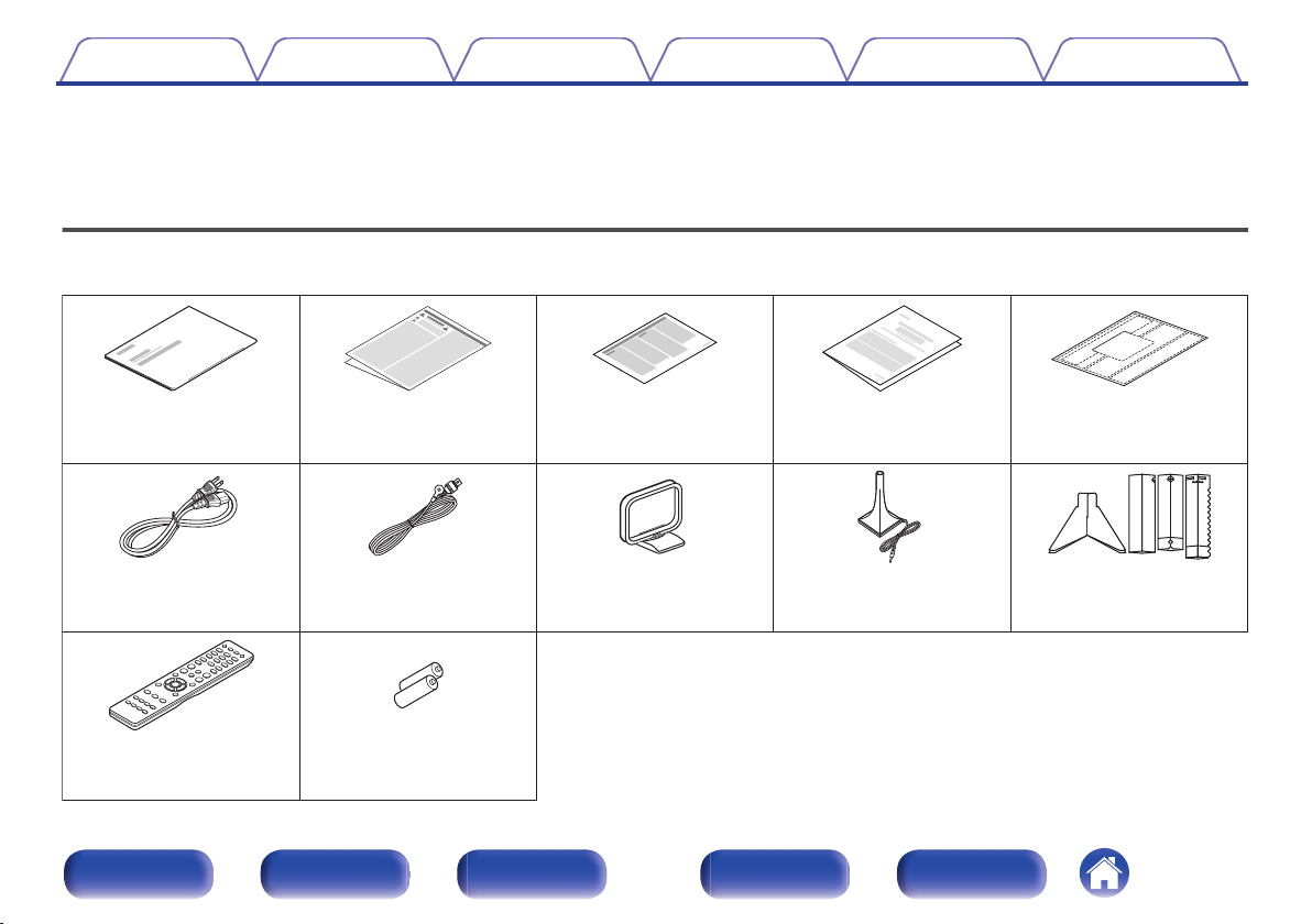
Accessories
Check that the following parts are supplied with the product.
.
Quick Start Guide Safety Instructions Notes on radio Warranty
(for North America
model only)
Cable labels
Power cord
FM indoor antenna
AM loop antenna Sound calibration
microphone
(ACM1HB)
Sound calibration
microphone stand
Remote control unit
(RC-1192)
R03/AAA batteries
Contents Connections Playback Settings Tips Appendix
7
Front panel Display Rear panel Remote Index
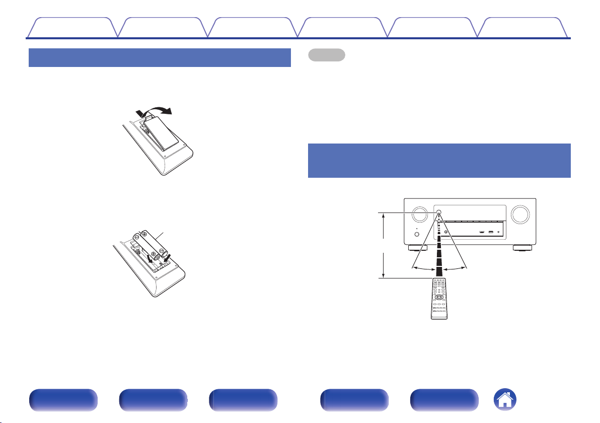
Inserting the batteries
1
Remove the rear lid in the direction of the arrow and
remove it.
.
2
Insert two batteries correctly into the battery
compartment as indicated.
.
R03/AAA batteries
3
Put the rear cover back on.
NOTE
0
To prevent damage or leakage of battery fluid:
0
Do not use a new battery together with an old one.
0
Do not use two different types of batteries.
0
Remove the batteries from the remote control unit if it will not be in use for long
periods.
0
If the battery fluid should leak, carefully wipe the fluid off the inside of the battery
compartment and insert new batteries.
Operating range of the remote control
unit
Point the remote control unit at the remote sensor when operating it.
.
Approx. 23 ft/7 m
30° 30°
Contents
Connections Playback Settings Tips Appendix
8
Front panel Display Rear panel Remote Index
Features
High quality sound
0
With discrete circuit technology, the power amplifier provides
identical quality for all 7-channels (125 Watts x 7-channels)
For optimum realism and stunning dynamic range, the power amplifier
section features discrete power devices (not integrated circuitry).
By using high current, high power discrete power devices, the amplifier
is able to easily drive high quality speakers.
0
Dolby Atmos (v
p. 263)
This unit is equipped with a decoder that supports Dolby Atmos audio
format. The placement or movement of sound is accurately reproduced
by the addition of overhead speakers, enabling you to experience an
incredibly natural and realistic surround sound field.
0
DTS:X
This unit is equipped with the DTS:X decoder technology. DTS:X
brings the home theater experience to new heights with its immersive
object based audio technology which removes the bounds of channels.
The flexibility of objects allows for sound to be scaled large or small
and moved around the room with greater accuracy than ever before
leading to a richer immersive audio experience.
High performance
0
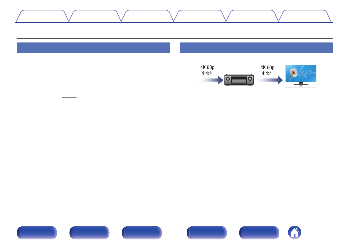
4K 60Hz input/output supported
.
When 4K Ultra HD (High Definition) is used, an input/output speed of 60
frames per second (60p) is achieved for video signals. When connected
to 4K Ultra HD and 60p video signal input compatible TV, you can enjoy
the sense of realism only available from high-definition images, even
when viewing fast-moving video.
This unit also supports image processing for 4K 60p, 4:4:4 and 24-bit
videos. By processing the video at the original resolution, this unit lets
you enjoy flawless, high-definition picture quality.
0
HDCP 2.2
This unit is compatible with HDCP2.2 copyright protection standard.
Contents
Connections Playback Settings Tips Appendix
9
Front panel Display Rear panel Remote Index
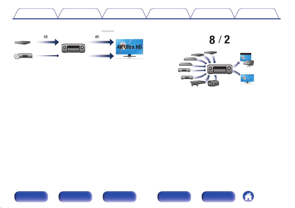
0
Digital video processor upscales analog video signals (SD
resolution) to HD (720p/1080p) and 4K (v p. 176)
.
4K
Up scaling
Up to 1080p
This unit is equipped with a 4K video upscaling function that allows
analog video or SD (Standard Definition) video to be output via HDMI at
4K (3840 × 2160 pixels) resolution. This function enables the device to
be connected to a TV using a single HDMI cable, and produces high
definition images for any video source.
0
HDMI connections enable connection to various digital AV
devices (8 inputs, 2 outputs)
.
Out
In
This unit is equipped with 8 HDMI inputs and 2 HDMI outputs enabling
connection to various HDMI compatible devices such as Blu-ray Disc
players, game consoles and HD video camcorders. This unit is
equipped with 2 monitor outputs, enabling you to project the same
image at the same time using this unit.
Contents
Connections Playback Settings Tips Appendix
10
Front panel Display Rear panel Remote Index
0
The device is equipped with a AirPlay
®
function in addition to
network functions such as Internet radio etc. (v p. 106)
.
You can enjoy a wide variety of content, including listening to Internet
Radio, playing audio files stored on your PC, and displaying
photographs stored on your PC on our television.
This unit also supports Apple AirPlay which lets you stream your music
library from an iPhone
®
, iPad
®
, iPod touch
®
or iTunes
®
.
0
Playback of DSD and FLAC files via USB and networks
This unit supports the playback of high resolution audio formats such as
DSD (2.8 MHz) and FLAC 192 kHz files. It provides high quality
playback of high resolution files.
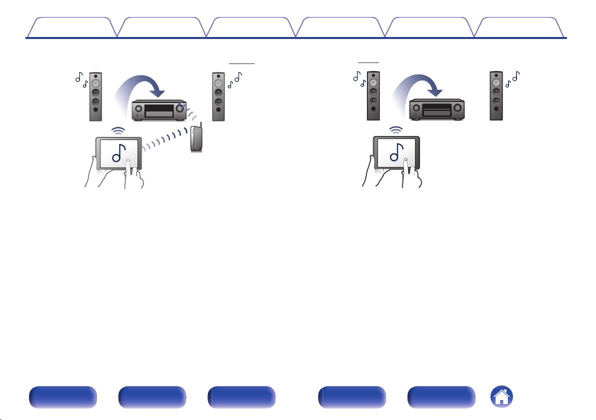
0
Wireless connection with Bluetooth devices can be carried out
easily (v
p. 75)
.
You can enjoy music simply by connecting wirelessly with your
smartphone, tablet, PC, etc.
0
Compatible with the “Denon 2015 AVR Remote”
z
for performing
basic operations of the unit with an iPad, iPhone or Android™
devices (Google, Amazon Kindle Fire)
“Denon 2015 AVR Remote” is application software that allows you to
perform basic operations with an iPad, iPhone, Android smartphone or
Android tablet such as turning the unit ON/OFF, controlling the volume,
and switching the source.
z
Download the appropriate “Denon 2015 AVR Remote” for your iOS or Android
devices. This unit needs to be connected to the same LAN or Wi-Fi (wireless
LAN) network that the iPhone or iPod touch is connected to.
Contents
Connections Playback Settings Tips Appendix
11
Front panel Display Rear panel Remote Index
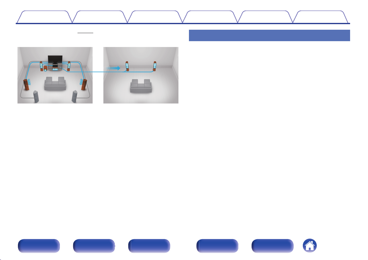
0
Multi-Room audio (v p. 120)
.
GMAIN ZONEHGZONE2H
You can select and play back the respective inputs in MAIN ZONE and
ZONE2.
In addition, when the All Zone Stereo function is used, the music being
played back in MAIN ZONE can be enjoyed in all the zones at the same
time. This is useful when you want to let the BGM propagate throughout
the whole house.
0
Energy-saving design
This unit is equipped with an ECO Mode function that allows you to
enjoy music and movies while reducing the power consumption during
use, and also an auto-standby function that automatically turns off the
power supply when the unit is not in use. This helps reduce
unnecessary power use.
Easy operation
0
“Setup Assistant” provides easy-to-follow setup instructions
First select the language when prompted. Then simply follow the
instructions displayed on the TV screen to set up the speakers, network,
etc.
0
Easy to use Graphical User Interface
This unit is equipped with a Graphical User Interface for improved
operability.
Contents Connections Playback Settings Tips Appendix
12
Front panel Display Rear panel Remote Index
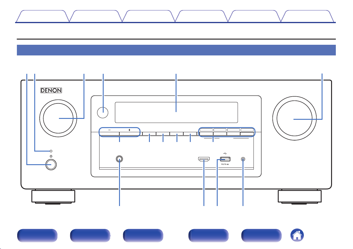
Part names and functions
Front panel
.
MASTER VOLUME
SOURCE SELECT
ONLINE
MEDIA
PLAYER
Blu-rayCBL/SAT
3214
ZONE2
ON/OFF
ZONE2
SOURCE
DIMMER STATUS
TUNER
PRESET CH
SETUP MICAUX1 - HDMI
PHONES
QUICK SELECT
er t y
uioQ0 Q1 Q2
Q
3
Q
4
Q
5
Q
6
qw
Contents
Connections Playback Settings Tips Appendix
13
Front panel Display Rear panel Remote Index
.
MASTER VOLUME
SOURCE SELECT
ONLINE
MEDIA
PLAYER
Blu-rayCBL/SAT
3214
ZONE2
ON/OFF
ZONE2
SOURCE
DIMMER STATUS
TUNER
PRESET CH
SETUP MICAUX1 - HDMI
PHONES
QUICK SELECT
tyq ew r
u i oQ0Q1
A
Power operation button (X)
Used to turn the power of the MAIN ZONE (room where this unit is
located) on/off (standby). (v
p. 65)
B
Power indicator
This is lit as follows according to the power status:
0
White: Power on
0
Off: Normal standby
0
Red:
0
When “HDMI Control” is set to “On” (v
p. 170)
0
When “HDMI Pass Through” is set to “On” (v
p. 171)
0
When “Network Control” is set to “Always On” (v p. 212)
C
SOURCE SELECT knob
This selects the input source. (v
p. 65)
D
Remote control sensor
This receives signals from the remote control unit. (v p. 8)
E
Display
This displays various pieces of information. (v
p. 16)
F
MASTER VOLUME knob
This adjusts the volume level. (v
p. 66)
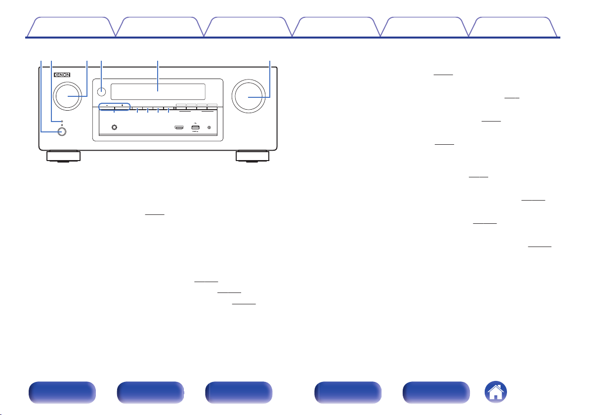
G
Tuner preset channel buttons
(TUNER PRESET CH +, –)
These select preset broadcast stations. (v
p. 84)
H
ZONE2 ON/OFF button
This turns the power of ZONE2 (separate room) on/off. (v p. 145)
I
ZONE2 SOURCE button
This selects the input source for ZONE2. (v p. 145)
J
DIMMER button
Each press of this switches the brightness of the display. (v p. 220)
K
STATUS button
Each press of this switches the status information that is shown on the
display.
Contents
Connections Playback Settings Tips Appendix
14
Front panel Display Rear panel Remote Index
.
MASTER VOLUME
SOURCE SELECT
ONLINE
MEDIA
PLAYER
Blu-rayCBL/SAT
3214
ZONE2
ON/OFF
ZONE2
SOURCE
DIMMER STATUS
TUNER
PRESET CH
SETUP MICAUX1 - HDMI
PHONES
QUICK SELECT
Q2
Q6Q4Q5Q3
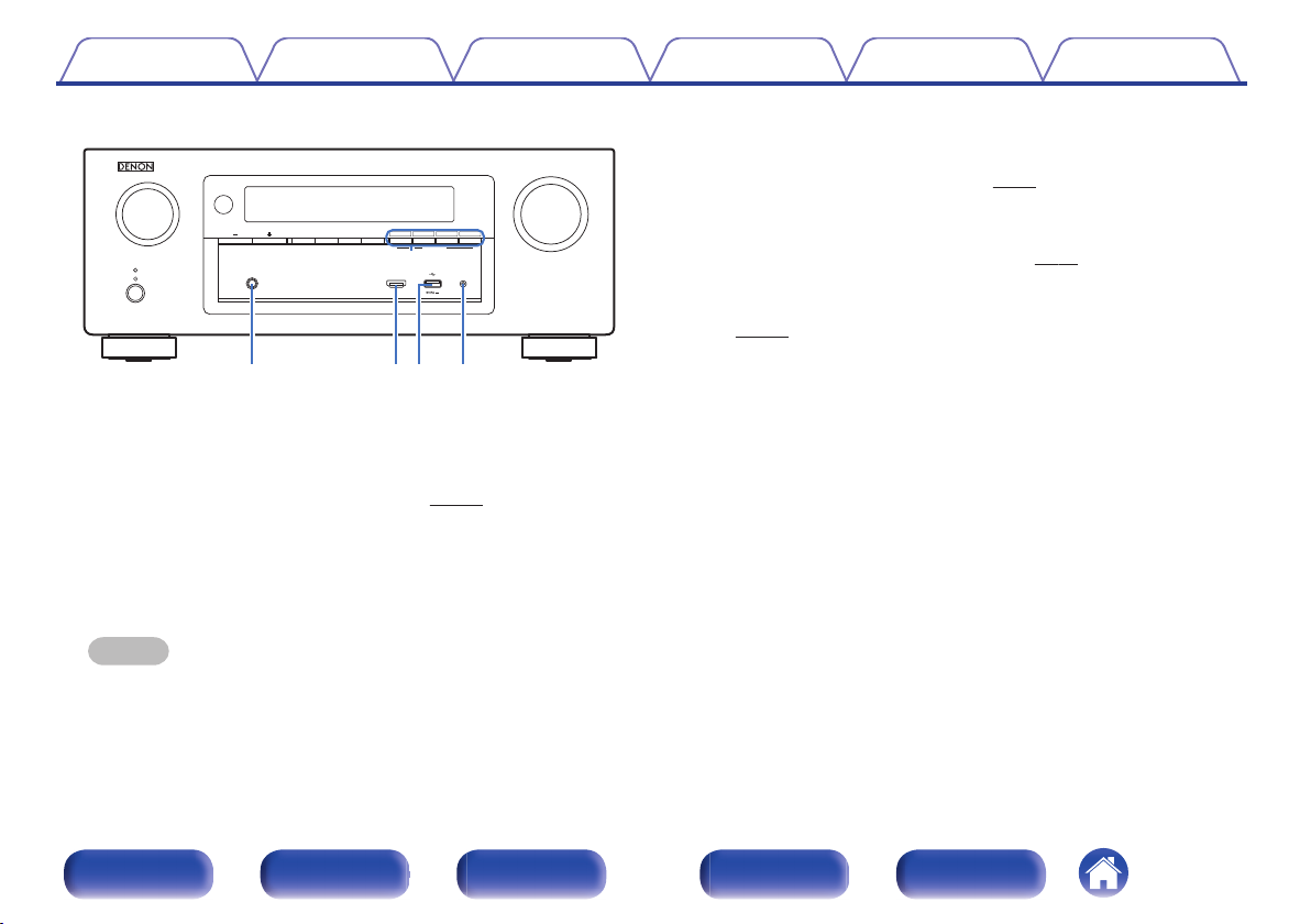
L
QUICK SELECT buttons
With a single press of any of these buttons, you can call up various
settings you’ve registered to each button such as the input source,
volume level and sound mode settings. (v p. 138)
M
Headphones jack (PHONES)
This is used to connect headphones.
When the headphones are plugged into this jack, audio will no longer
be output from the connected speakers or from the PRE OUT
connectors.
NOTE
0
To prevent hearing loss, do not raise the volume level excessively when using
headphones.
N
AUX1-HDMI connector
This is used to connect HDMI output compatible devices such as video
camcorders and game consoles. (v p. 55)
O
USB port (T)
This is used to connect USB storages (such as USB memory devices)
and the USB cable supplied with iPod. (v p. 56)
P
SETUP MIC jack
This is used to connect the supplied Sound calibration microphone.
(v p. 188)
Contents Connections Playback Settings Tips Appendix
15
Front panel Display Rear panel Remote Index
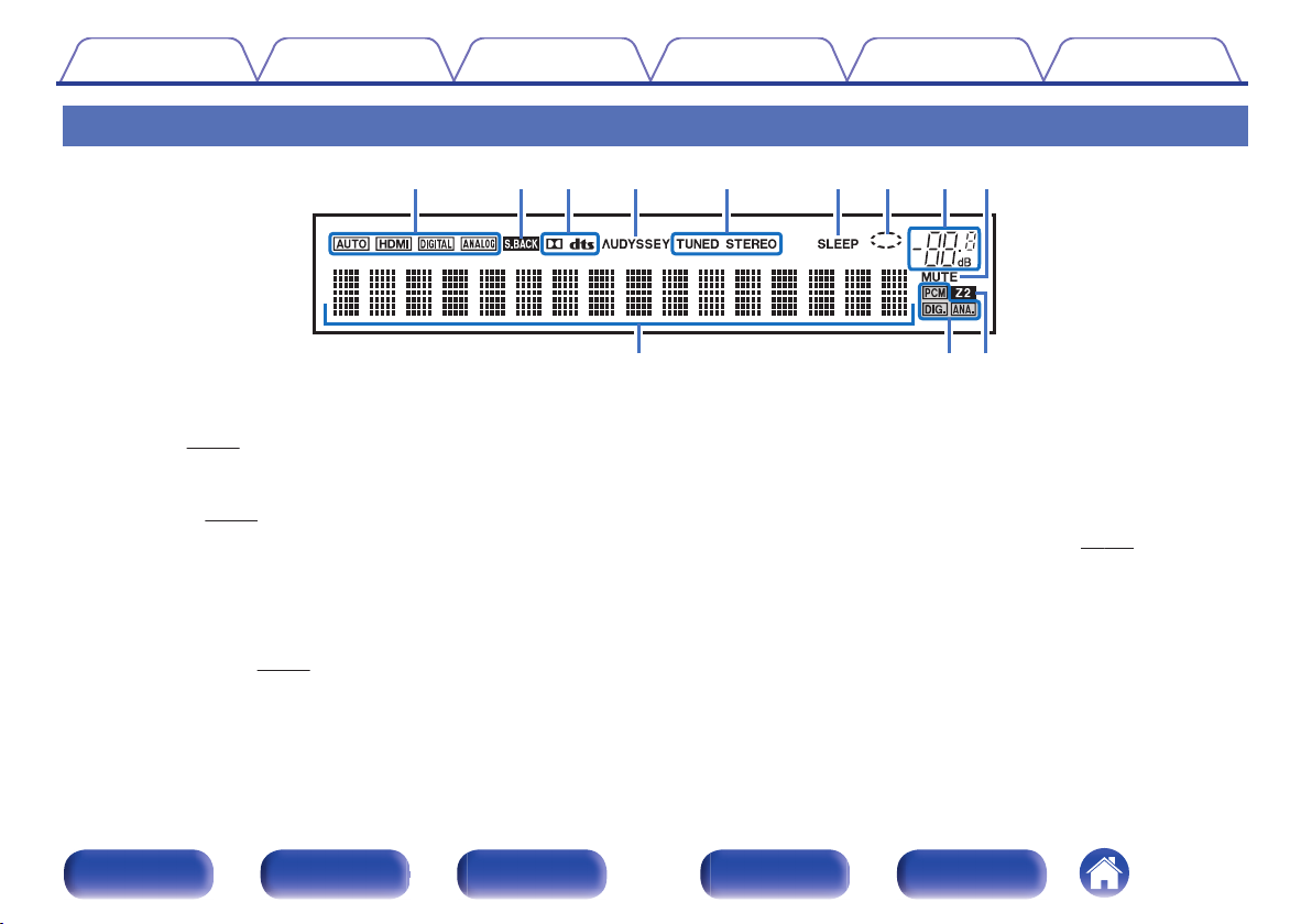
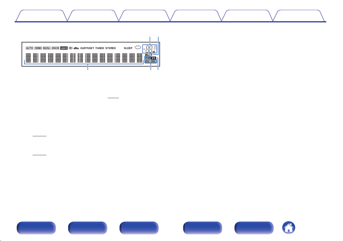
Display
.
iouytrewq
Q
0
Q
1
Q
2
A
Input mode indicators
These light according to the audio input mode settings of each input
source. (v p. 183)
B
Surround back indicator
This lights when audio signals are being output from the surround back
speakers. (v p. 198)
C
Decoder indicators
These light when Dolby or DTS signals are input or when the Dolby or
DTS decoder is running.
D
Audyssey
®
indicator
This lights when “MultEQ
®
XT”, “Dynamic EQ” or “Dynamic Volume”
has been set up. (v
p. 160)
E
Tuner reception mode indicators
These light up according to the reception conditions when the input
source is set to “Tuner”.
TUNED: Lights up when the broadcast is properly tuned in.
STEREO: Lights up when receiving FM stereo broadcasts.
F
Sleep timer indicator
This lights when the sleep mode is selected. (v p. 136)
G
Circle indicator
This is displayed when the input source is “Online Music” or “iPod/USB”
when you are playing back music.
Contents Connections Playback Settings Tips Appendix
16
Front panel Display Rear panel Remote Index
.
io
Q
2
Q
1
Q
0
H
Volume indicator
I
MUTE indicator
This blinks while the sound is muted. (v
p. 66)
J
Information display
The input source name, sound mode, setting values and other
information are displayed here.
K
Input signal indicators
The respective indicator will light corresponding to the input signal.
(v
p. 183)
L
ZONE2 indicator
This lights up when ZONE2 (separate room) power is turned on.
(v
p. 145)
Contents
Connections Playback Settings Tips Appendix
17
Front panel Display Rear panel Remote Index
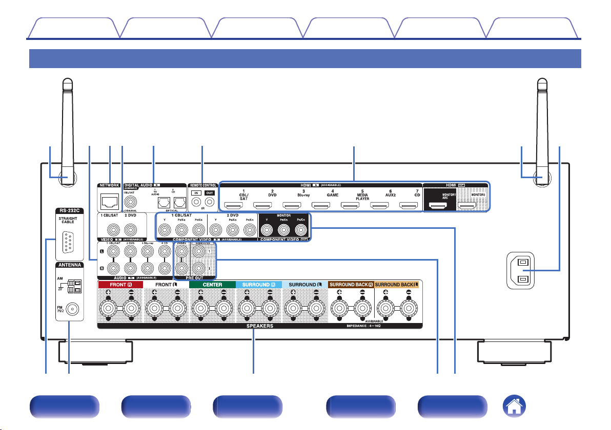
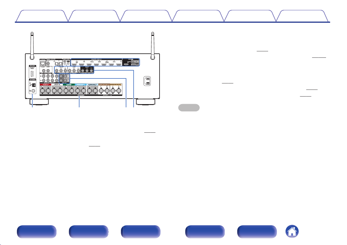
Rear panel
.
AC IN
q
oQ
0
Q
1
Q
2
Q
3
wer t y u q i
Contents
Connections Playback Settings Tips Appendix
18
Front panel Display Rear panel Remote Index
.
AC IN
qq
wer
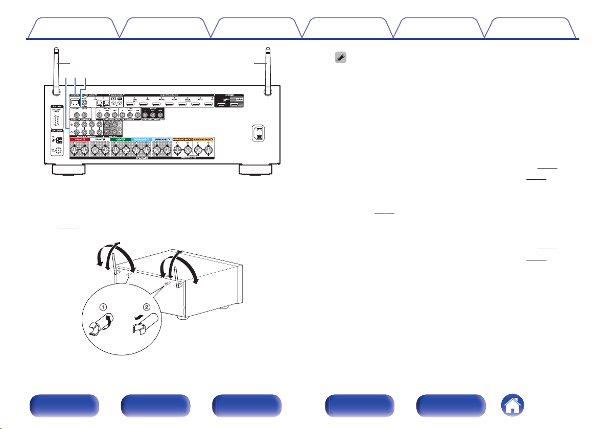
A
Rod antennas for Bluetooth/wireless LAN
Stand this antenna upright when connecting to a network via wireless
LAN, or when connecting to a handheld device via Bluetooth.
(v p. 61)
.
90°
320°
320°
90°
0
The antenna clip can be removed from the rear panel.
A
Rotate the antenna clip 90 degrees to the left.
B
Pull the antenna clip out towards yourself.
0
The antenna clip is needed when transporting this unit. Keep it in a
safe place.
0
Attach the antenna clip by following the steps for removing it in
reverse.
B
Analog audio connectors (AUDIO)
Used to connect devices equipped with analog audio connectors.
0
“Connecting a set-top box (Satellite tuner/cable TV)” (v
p. 53)
0
“Connecting a DVD player or Blu-ray Disc player” (v p. 54)
C
NETWORK connector
Used to connect to a LAN cable when connecting to a wired LAN
network. (v
p. 60)
D
Video connectors (VIDEO)
Used to connect devices equipped with video connectors.
0
“Connecting a set-top box (Satellite tuner/cable TV)” (v
p. 53)
0
“Connecting a DVD player or Blu-ray Disc player” (v
p. 54)
Contents
Connections Playback Settings Tips Appendix
19
Front panel Display Rear panel Remote Index
.
AC IN
o
ytu i
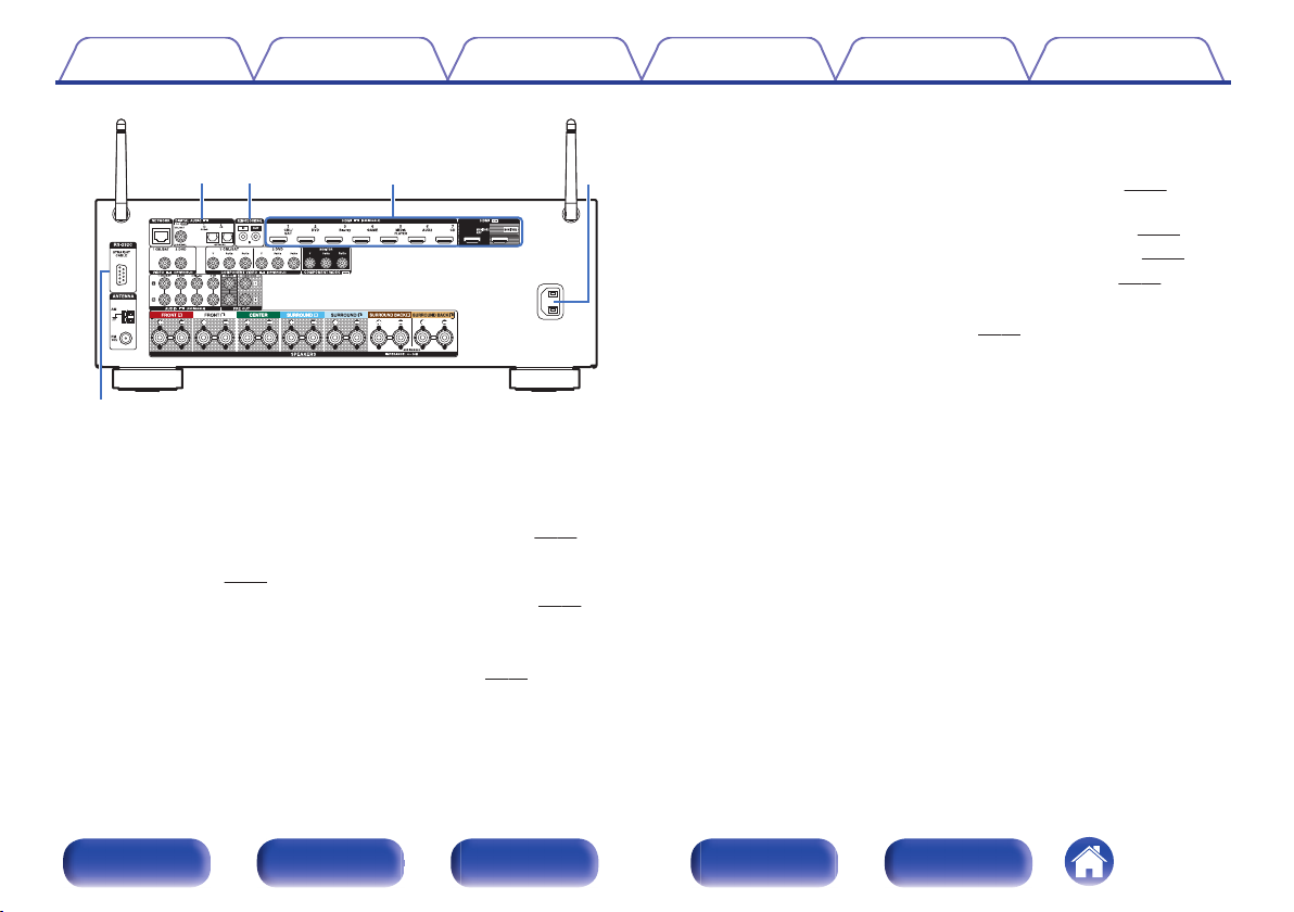
E
Digital audio connectors (DIGITAL AUDIO)
Used to connect devices equipped with digital audio connectors.
0
“Connection 2 : TV equipped with an HDMI connector and
incompatible with the ARC (Audio Return Channel)” (v
p. 50)
0
“Connection 3 : TV equipped without an HDMI
connector” (v
p. 51)
0
“Connecting a set-top box (Satellite tuner/cable TV)” (v p. 53)
F
REMOTE CONTROL jack
Used to connect infrared receivers/transmitters in order to operate this
unit and external devices from a different room. (v
p. 62)
G
HDMI connectors
Used to connect devices equipped with HDMI connectors.
0
“Connection 1 : TV equipped with an HDMI connector and
compatible with the ARC (Audio Return Channel)” (v p. 49)
0
“Connection 2 : TV equipped with an HDMI connector and
incompatible with the ARC (Audio Return Channel)” (v p. 50)
0
“Connecting a set-top box (Satellite tuner/cable TV)” (v
p. 53)
0
“Connecting a DVD player or Blu-ray Disc player” (v
p. 54)
H
AC inlet (AC IN)
Used to connect the power cord. (v p. 63)
I
RS-232C connector
Used to connect home automation controller devices fitted with
RS-232C connectors. Consult the owner’s manual of the home
automation controller for more information about serial control of this
unit.
Perform the operation below beforehand.
A
Turn on the power of this unit.
B
Turn off the power of this unit from the external controller.
C
Check that the unit is in the standby mode.
Contents Connections Playback Settings Tips Appendix
20
Front panel Display Rear panel Remote Index
.
AC IN
Q
0
Q
1
Q
2
Q
3
J
FM/AM antenna terminals (ANTENNA)
Used to connect FM antennas and AM loop antennas. (v p. 58)
K
Speaker terminals (SPEAKERS)
Used to connect speakers. (v
p. 33)
L
PRE OUT connectors
Used to connect a subwoofer with built-in amplifier or an external power
amplifier.
0
“Connecting the subwoofer” (v
p. 34)
0
“Connection 2 : Connection using an external amplifier” (v p. 144)
M
Component video connectors (COMPONENT VIDEO)
Used to connect devices equipped with component video connectors.
0
“Connection 3 : TV equipped without an HDMI
connector” (v
p. 51)
0
“Connecting a set-top box (Satellite tuner/cable TV)” (v
p. 53)
0
“Connecting a DVD player or Blu-ray Disc player” (v p. 54)
NOTE
0
Do not touch the inner pins of the connectors on the rear panel. Electrostatic
discharge may cause permanent damage to the unit.
Contents Connections Playback Settings Tips Appendix
21
Front panel Display Rear panel Remote Index
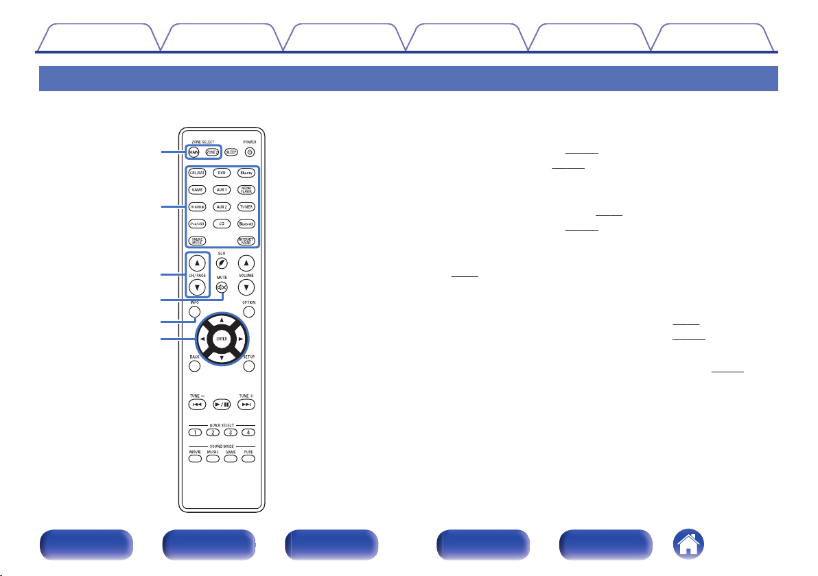
Remote control unit
A
ZONE SELECT buttons
These switch the zone (MAIN ZONE, ZONE2) that is operated through
the remote control unit.
0
“Playback in ZONE2” (v
p. 145)
0
“Menu operations” (v p. 150)
B
Input source select buttons
These selects the input source.
0
“Selecting the input source” (v
p. 65)
0
“Playback in ZONE2” (v p. 145)
C
Channel/page search buttons (CH/PAGE df)
These select radio stations registered to presets or switch pages.
(v
p. 84)
D
MUTE button (:)
This mutes the output audio.
0
“Turning off the sound temporarily (Muting)” (v
p. 66)
0
“Turning off the sound temporarily (Muting)” (v
p. 146)
E
Information button (INFO)
This displays the status information on the TV screen. (v p. 224)
F
Cursor buttons (uio p)
These select items.
e
t
r
y
q
w
Contents
Connections Playback Settings Tips Appendix
22
Front panel Display Rear panel Remote Index
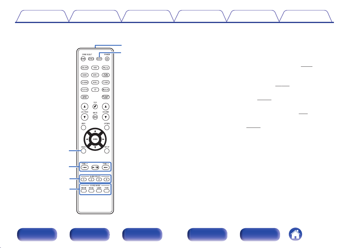
G
BACK button
This returns to the previous screen.
H
System buttons
These perform playback related operations.
Tuning up / Tuning down buttons (TUNE +, –)
These select either FM broadcast or AM broadcast. (v p. 81)
I
QUICK SELECT buttons (1 – 4)
These call up settings registered to each button, such as input source,
volume level and sound mode settings. (v
p. 138)
J
SOUND MODE buttons
These select the sound mode. (v
p. 121)
K
Remote control signal transmitter
This transmits signals from the remote control unit. (v p. 8)
L
SLEEP button
This sets the sleep timer. (v p. 136)
Q2
Q1
Q0
o
i
u
Contents
Connections Playback Settings Tips Appendix
23
Front panel Display Rear panel Remote Index
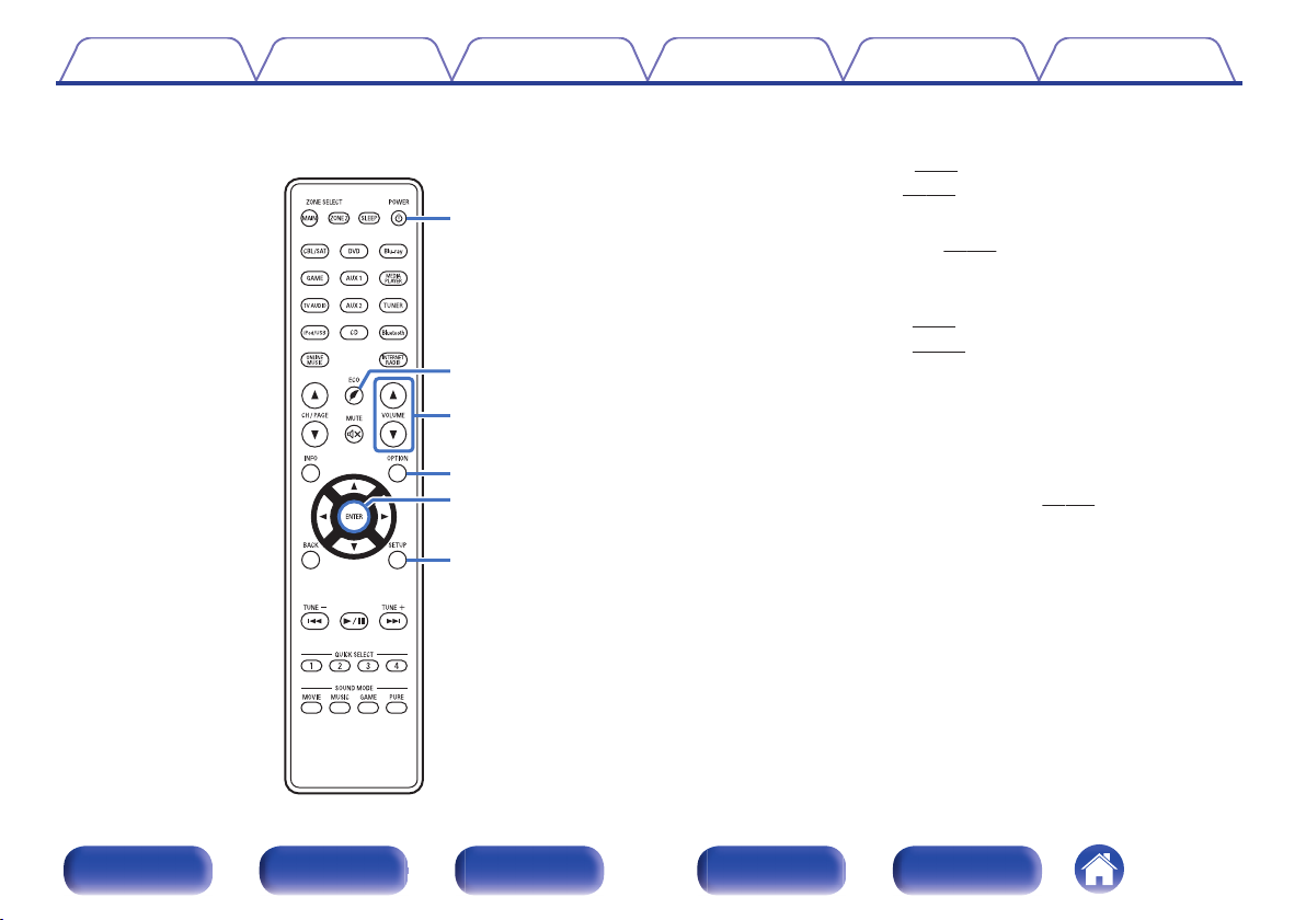
M
POWER button (X)
This turns the power on/off.
0
“Turning the power on” (v p. 65)
0
“Playback in ZONE2” (v
p. 145)
N
ECO Mode button (G)
This switches to ECO Mode. (v
p. 215)
O
VOLUME buttons (df)
These adjusts the volume level.
0
“Adjusting the volume” (v
p. 66)
0
“Adjusting the volume” (v p. 146)
P
OPTION button
This displays the option menu on the TV screen.
Q
ENTER button
This determines the selection.
R
SETUP button
This displays the menu on the TV screen. (v p. 150)
Q3
Q5
Q4
Q8
Q6
Q7
Contents
Connections Playback Settings Tips Appendix
24
Front panel Display Rear panel Remote Index
o
Contents
Connecting speakers 26
Connecting a TV 48
Connecting a playback device 52
Connecting an iPod or USB memory device to the USB port 56
Connecting an FM/AM antenna 58
Connecting to a home network (LAN) 60
Connecting an external control device 62
Connecting the power cord 63
NOTE
0
Do not plug in the power cord until all connections have been completed.
However, when the “Setup Assistant” is running, follow the instructions in the
“Setup Assistant” (page 8 in the separate “Quick Start Guide”) screen for making
connections. (During “Setup Assistant” operation, the input/output connectors do
not conduct current.)
0
Do not bundle power cords together with connection cables. Doing so can result in
noise.
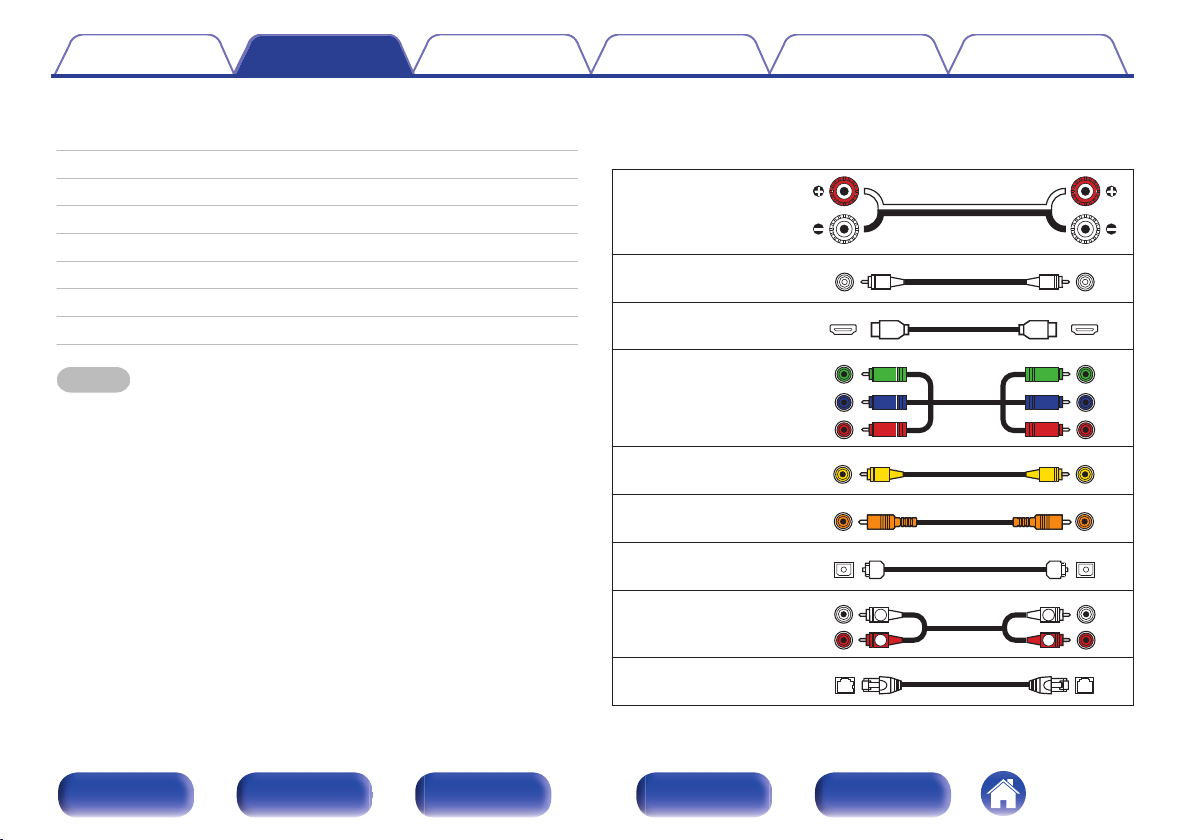
o
Cables used for connections
Provide necessary cables according to the devices you want to
connect.
Speaker cable
.
Subwoofer cable
.
HDMI cable
.
Component video cable
.
Video cable
.
Coaxial digital cable
.
Optical cable
.
Audio cable
.
R
L
R
L
LAN cable
.
Contents Connections Playback Settings Tips Appendix
Connections
25
Front panel Display Rear panel Remote Index

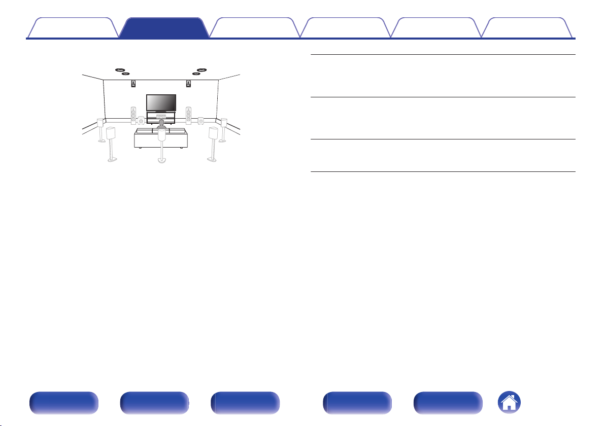
Connecting speakers
Install speakers and connect them to this unit. (“Speaker installation” (v p. 26), “Speaker connection” (v p. 33))
Speaker installation
Determine the speaker system depending on the number of speakers you
are using and install each speaker and subwoofer in the room.
Speaker installation is explained using this example of a typical
installation.
.
C
FL FR
SBL
SBR
SB
SW1
SW2
SL SR
FL/FR
(Front speaker left/
right):
Place the FRONT left and right speakers an
equal distance from the main listening position.
The distance between each speaker and your TV
should also be the same.
C
(Center speaker):
Place the CENTER speaker in between the front
speakers and above or below your TV.
SL/SR
(Surround speaker left/
right):
Place the SURROUND left and right speakers an
equal distance to the left and right sides of the
main listening position. If you don’t have
surround back speakers, move the surround
speakers slightly behind your listening position.
SBL/SBR
(Surround back
speaker left/right):
Place the SURROUND BACK left and right
speakers an equal distance from the main
listening position and directly behind the main
listening position. When using a single surround
back speaker (SB), place it directly behind the
listening position.
SW 1/2
(Subwoofer) :
Place the SUBWOOFER at a convenient location
near the front speakers. If you have two
subwoofers, place them asymmetrically across
the front of your room.
Contents Connections Playback Settings Tips Appendix
26
Front panel Display Rear panel Remote Index
.
FHL FHR
TFR
TFL
TMR
TML
FHL/FHR
(Front height speaker
left/right):
Place the FRONT HEIGHT left and right speakers
directly above the front speakers. Mount them as
close to the ceiling as possible and aim them
towards the main listening position.
TFL/TFR
(Top front speaker
left/right):
Mount the TOP FRONT left and right speakers on
the ceiling slightly in front of your main listening
position and aligned with the left and right front
speakers.
TML/TMR
(Top middle speaker
left/right):
Mount the TOP MIDDLE left and right speakers
directly above the main listening position and
aligned with the left and right front speakers.
Contents Connections Playback Settings Tips Appendix
27
Front panel Display Rear panel Remote Index
.
FDL FDR
SDL SDR
FDL/FDR
(Front Dolby speaker
left/right):
Place the FRONT Dolby Atmos Enabled speaker
on the front speaker. For a Dolby Atmos Enabled
integrated with a front speaker, place the Dolby
Atmos Enabled speaker instead of the front
speaker.
SDL/SDR
(Surround Dolby
speaker left/right):
Place the SURROUND Dolby Atmos Enabled
speaker on the surround speaker. For a Dolby
Atmos Enabled speaker integrated with a surround
speaker, place the Dolby Atmos Enabled speaker
instead of the surround speaker.
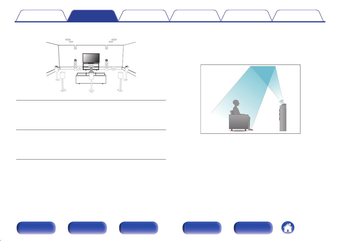
About Dolby Atmos Enabled speakers
Dolby Atmos Enabled speakers reflect the sound off the ceiling to allow
the sound to come from over your head by using a special upward-
pointing speaker that is placed on the floor.
You can enjoy the Dolby Atmos 3D sound even in an environment where
speakers cannot be installed on the ceiling.
.
Contents
Connections Playback Settings Tips Appendix
28
Front panel Display Rear panel Remote Index
0
This unit is compatible with Dolby Atmos and DTS:X which offers an even wider
and deeper surround sensation.
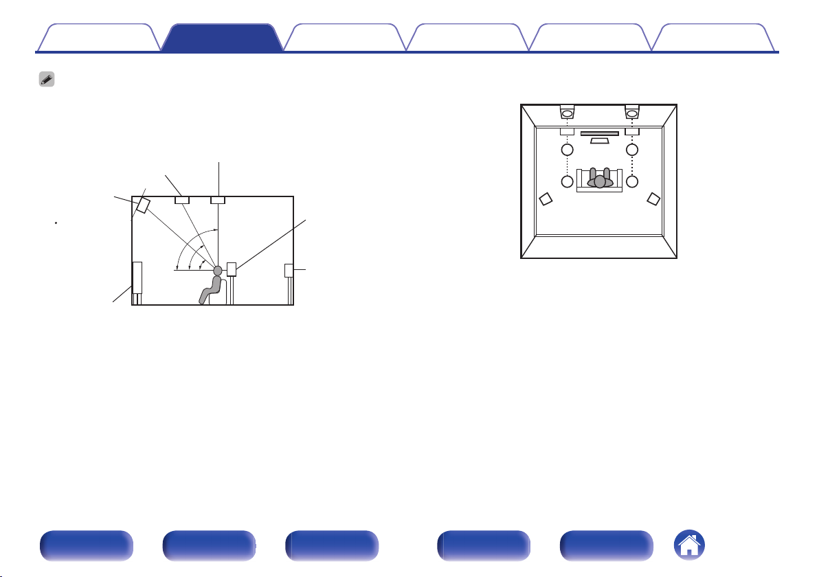
0
Use the illustration below as a guide for how high each speaker should be
installed. The height does not need to be exactly the same.
.
z1
z2
z3
Front height
speaker
z1: 30° – 45° z2: 30° – 55°
z3: 65° – 100°
GViewed from the sideH
Top middle speaker
Top front speaker
Front speaker
Surround
speaker
Surround
back
speaker
Point slightly
downwards
.
SL
FHL
TML
TFL
FL
SR
FHR
TMR
TFR
FR
C
Height speakers layout
GViewed from the topH
Contents
Connections Playback Settings Tips Appendix
29
Front panel Display Rear panel Remote Index
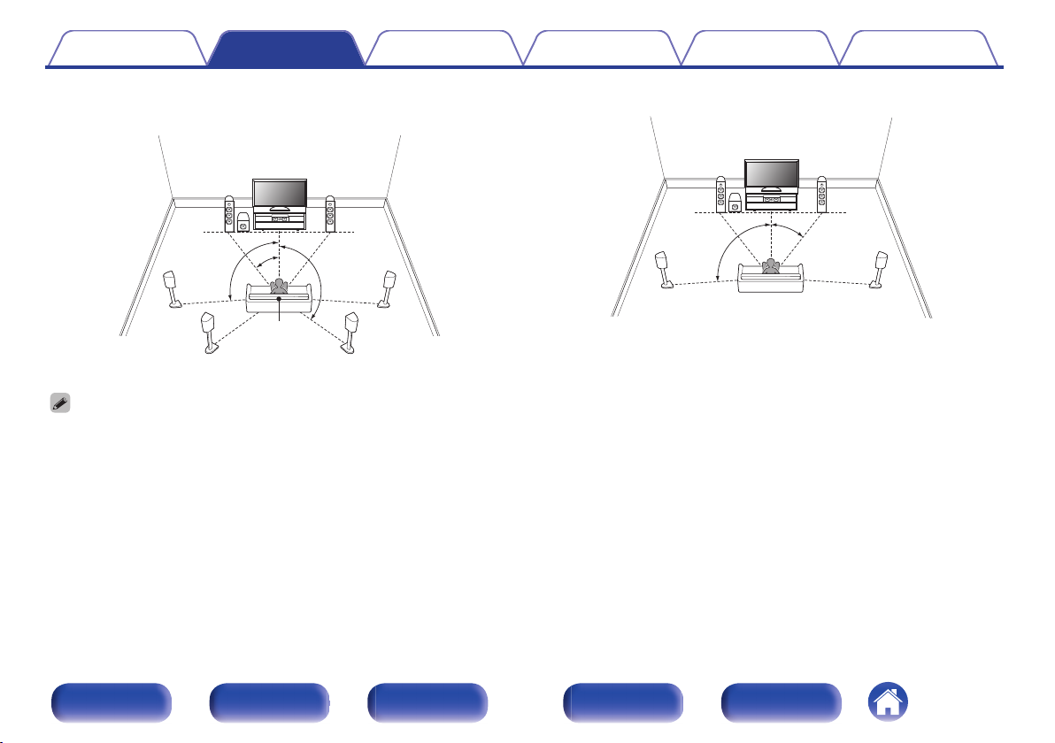
o
When 7.1-channel speakers are installed using
surround back speakers
.
z1
z2
z3
FL
SW
C
SL
SBL
FR
SR
SBR
Listening
position
z
1:22° - 30°
z
2:90° - 110°
z
3:135° - 150°
0
When using a single surround back speaker, place it directly behind the listening
position.
o
When 5.1-channel speakers are installed
.
z1
z2
FL
SW
C
SL
FR
SR
z
1:22° - 30°
z
2:120°
Contents
Connections Playback Settings Tips Appendix
30
Front panel Display Rear panel Remote Index
 Loading...