


|
Export |
MODULENS O® |
|
EN |
|
|
|
Oil-fired condensing boilers |
|
|
|
AFC 18 - AFC 24 - AFC 30 |
|
User Guide
300026440-001-03

Contents
1 |
Introduction ................................................................................................ |
|
|
4 |
|
1.1 |
Symbols used ....................................................... |
4 |
|
|
|
1.1.1 |
Symbols used in the manual ................................... |
4 |
|
|
1.1.2 |
Symbols used on the equipment ............................. |
4 |
|
1.2 |
Abbreviations ........................................................ |
5 |
|
|
1.3 |
General |
.................................................................. |
5 |
|
|
1.3.1 |
Manufacturer’s liability ............................................. |
5 |
|
|
1.3.2 |
Installer’s liability ..................................................... |
6 |
|
|
1.3.3 |
User’s liability .......................................................... |
6 |
|
1.4 |
Certifications ......................................................... |
6 |
|
2 |
Safety instructions and recommendations .............................................. |
7 |
||
|
2.1 |
Safety instructions ............................................... |
7 |
|
|
2.2 |
Recommendations ................................................ |
7 |
|
3 |
Description .................................................................................................. |
|
|
9 |
|
3.1 |
General description .............................................. |
9 |
|
|
3.2 |
Main parts .............................................................. |
9 |
|
|
3.3 |
Control panel ....................................................... |
10 |
|
|
|
3.3.1 |
Description of the keys .......................................... |
10 |
|
|
3.3.2 |
Description of the display ...................................... |
11 |
|
|
3.3.3 |
Browsing in the menus .......................................... |
14 |
4 |
Operating the appliance .......................................................................... |
|
|
15 |
|
4.1 |
Putting the appliance into operation ................ |
15 |
|
|
4.2 |
Reading out measured values ........................... |
15 |
|
|
4.3 |
Changing the settings ........................................ |
17 |
|
|
|
4.3.1 |
Setting the set point temperatures ........................ |
17 |
|
|
4.3.2 |
Selecting the operating mode ............................... |
18 |
|
|
4.3.3 |
Forcing domestic hot water production ................. |
19 |
|
|
4.3.4 |
Setting the contrast and lighting on the |
|
|
|
|
display ................................................................... |
19 |
|
|
4.3.5 |
Setting the time and date ...................................... |
20 |
|
|
4.3.6 |
Selecting a timer programme ................................ |
20 |
|
|
4.3.7 |
Customising a timer programme ........................... |
21 |
1 |
|
|
|
09/01/2014 - 300026440-001-03 |
|
|

Contents |
|
|
4.4 |
Installation shutdown |
.........................................23 |
4.5 |
Antifreeze protection .......................................... |
23 |
5 |
Checking and maintenance |
..................................................................... |
25 |
|
5.1 |
General instructions ........................................... |
25 |
|
5.2 |
Periodic checks .................................................. |
25 |
|
5.3 ............................................... |
Filling the system |
26 |
|
5.4 ............................. |
Bleeding the heating system |
28 |
|
5.5 ..................................... |
Draining the installation |
30 |
6 |
Troubleshooting ....................................................................................... |
|
31 |
|
6.1 |
Anti-hunting ........................................................ |
31 |
|
6.2 |
Messages (Code type Bxx or Mxx) .................... |
31 |
|
6.3 |
Faults (Code type Lxx or Dxx) ........................... |
33 |
7 |
Technical specifications .......................................................................... |
|
|
38 |
|
7.1 |
Technical specifications |
....................................38 |
|
|
|
7.1.1 |
Boiler specifications .............................................. |
38 |
8 |
Energy savings ......................................................................................... |
|
|
40 |
|
8.1 |
Energy-saving advice ......................................... |
40 |
|
|
8.2 |
Recommendations .............................................. |
40 |
|
9 |
Warranty .................................................................................................... |
|
|
41 |
|
9.1 |
General |
................................................................ |
41 |
|
9.2 |
Warranty terms ................................................... |
41 |
|
2 |
|
|
|
09/01/2014 - 300026440-001-03 |
|
|

3 |
|
|
|
09/01/2014 - 300026440-001-03 |
|
|
AFC 18 - AFC 24 - AFC 30 |
1. Introduction |
1Introduction
1.1Symbols used
1.1.1.Symbols used in the manual
In these instructions, various danger levels are employed to draw the user’s attention to particular information. In so doing, we wish to safeguard the user’s safety, obviate hazards and guarantee correct operation of the appliance.
DANGER
Risk of a dangerous situation causing serious physical injury.
WARNING
Risk of a dangerous situation causing slight physical injury.
CAUTION
Risk of material damage.
Signals important information.
¼Signals a referral to other instructions or other pages in the instructions.
1.1.2.Symbols used on the equipment
4Protective earthing
~Alternating current
Before installing and commissioning the device, read carefully the instruction manuals provided.
Dispose of the used products in an appropriate recovery and recycling structure.
This appliance must be connected to the protective earth.
D000241-C
09/01/2014 - 300026440-001-03 |
|
|
|
4 |
|
|
1. Introduction |
|
AFC 18 - AFC 24 - AFC 30 |
1 |
2 |
Caution: danger, live parts. |
|
|
Disconnect the mains power prior to any operations. |
M002628-A
1.2Abbreviations
43CE: Collective conduit for sealed boiler
43WV: 3-way valve
4PCU: Primary Control Unit - PCB for managing burner operation
4PSU: Parameter Storage Unit - Parameter storage for PCBs PCU and SU
4SCU: Secondary Control Unit - DIEMATIC iSystem control panel PCB
4SU: Safety Unit - Safety PCB
4DHW: Domestic hot water
4HL: High Load - DHW tank with plate exchanger
4SL: Standard Load - DHW tank with coil
4SHL: Solar High Load - Solar DHW tank with plate exchanger
4MC: Boiler module
4Hi: Lower heating value LHV (Nett)
4Hs: Higher heating value HHV (Gross)
4CFC: Chlorofluorocarbon
1.3General
1.3.1.Manufacturer’s liability
Our products are manufactured in compliance with the requirements of the various applicable European Directives. They are therefore
delivered with [marking and all relevant documentation.
In the interest of customers, we are continuously endeavouring to make improvements in product quality. All the specifications stated in this document are therefore subject to change without notice.
Our liability as the manufacturer may not be invoked in the following cases:
4Failure to abide by the instructions on using the appliance.
4Faulty or insufficient maintenance of the appliance.
4Failure to abide by the instructions on installing the appliance.
5 |
|
|
|
09/01/2014 - 300026440-001-03 |
|
|

AFC 18 - AFC 24 - AFC 30 |
1. Introduction |
1.3.2.Installer’s liability
The installer is responsible for the installation and inital start up of the appliance. The installer must respect the following instructions:
4Read and follow the instructions given in the manuals provided with the appliance.
4Carry out installation in compliance with the prevailing legislation and standards.
4Perform the initial start up and carry out any checks necessary.
4Explain the installation to the user.
4If a maintenance is necessary, warn the user of the obligation to check the appliance and maintain it in good working order.
4Give all the instruction manuals to the user.
1.3.3.User’s liability
To guarantee optimum operation of the appliance, the user must respect the following instructions:
4Read and follow the instructions given in the manuals provided with the appliance.
4Call on qualified professionals to carry out installation and initial start up.
4Get your installer to explain your installation to you.
4Have the required checks and services done.
4Keep the instruction manuals in good condition close to the appliance.
This appliance is not intended to be used by persons (including children) whose physcial, sensory or mental capacity is impaired or persons with no experience or knowledge, unless they have the benefit, through the intermediary of a person responsible for their safety, of supervision or prior instructions regarding use of the appliance. Care should be taken to ensure that children do not play with the appliance.
To prevent hazardous situations from arising, if the mains lead is damaged it must be replaced by the original manufacturer, the manufacturer’s dealer or another suitably skilled person.
1.4Certifications
CE identification no |
CE : 1312 CN 5691 |
Type of connection |
Chimney: B23, B23P |
|
Flue gas outlet: C13(x), C33(x), C93(x) |
09/01/2014 - 300026440-001-03 |
|
|
|
6 |
|
|
2. Safety instructions and recommendations |
AFC 18 - AFC 24 - AFC 30 |
2Safety instructions and recommendations
2.1Safety instructions
DANGER
If you smell flue gases:
1. Switch the appliance off.
2. Open the windows.
3. Evacuate the premises.
4. Contact a qualified professional.
WARNING
Depending on the settings of the appliance:
4 Thetemperatureofthefluegasconduitsmayexceed 60°C.
4 The temperature of the radiators may reach 95°C.
4 Thetemperatureofthedomestichotwatermayreach 80°C (depending on the set point temperature and activation of the antilegionella function).
CAUTION
4 Do not neglect to service the appliance. For completely safe and optimum operation, you must have your boiler regularly serviced by an approved installer.
4 Before any work, switch off the mains supply to the appliance.
4 Avoid direct contact with the flame viewport.
2.2Recommendations
WARNING
Only qualified professionals are authorised to work on the appliance and the installation.
4Regularly check the water pressure in the installation (minimum pressure 0.8 bar (0.08 MPa), recommended pressure between
1.5 and 2 bar (0.15 MPa and 0.2 MPa))
4Keep the appliance accessible at all times.
7 |
|
|
|
09/01/2014 - 300026440-001-03 |
|
|

AFC 18 - AFC 24 - AFC 30 |
2. Safety instructions and recommendations |
4Never remove or cover labels and rating plates affixed to the appliance.Labelsandratingplatesmustbelegiblethroughoutthe entire lifetime of the appliance.
4The appliance should be on Summer or Antrifreeze mode rather than switched off to guarantee the following functions:
-Anti blocking of pumps
-Antifreeze protection
09/01/2014 - 300026440-001-03 |
|
|
|
8 |
|
|
3. Description |
AFC 18 - AFC 24 - AFC 30 |
3Description
3.1General description
Floor-standing condensing oil boiler
4Heating only (Optional domestic hot water production in combination with a DHW tank).
4High efficiency heating.
4Low pollutant emissions.
4Modulating oil burner preassembled and preset.
4Stainless steel heating body.
4Top of the range electronic DIEMATIC iSystem control panel.
4Flue gas evacuation by a forced flue or chimney type connection.
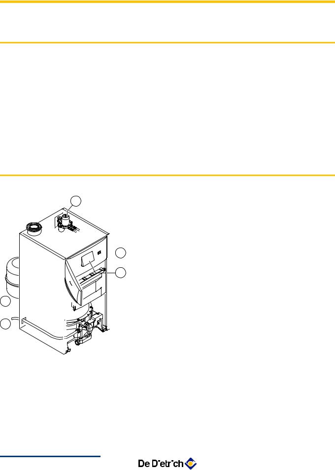
3.2Main parts
1 |
Oil filter (40 µm) + deaerator + stop valve |
1 |
On/Off switch |
2 |
|
3 |
Command module |
4 |
Expansion vessel 18 litres |
5 |
Condensates evacuation pipe |
2 |
|
3 |
|
4
5
C003260-B
9 |
|
|
|
09/01/2014 - 300026440-001-03 |
|
|

AFC 18 - AFC 24 - AFC 30 |
3. Description |
3.3Control panel
3.3.1.Description of the keys
|
|
|
|
|
|
|
|
|
|
|
|
|
A000866-A |
|
0 |
2 |
4 |
6 |
8 |
10 |
12 |
14 |
16 |
18 |
20 |
22 |
24 |
A |
|
|
|
|
|
|
|
|
|
|
|
|
|
B |
BAR |
|
|
|
|
|
|
|
|
|
|
|
|
|
|
|
|
|
|
|
|
|
|
|
|
|
|
|
pb AUTOxc g m rjM |
|
|
|
|||||||||
C |
( |
|
|
' STD |
|
|
|
t |
|
|
|
||
|
|
|
|
|
|
|
|
|
|||||
|
D |
|
|
|
|
E |
|
|
|
|
|
|
F |
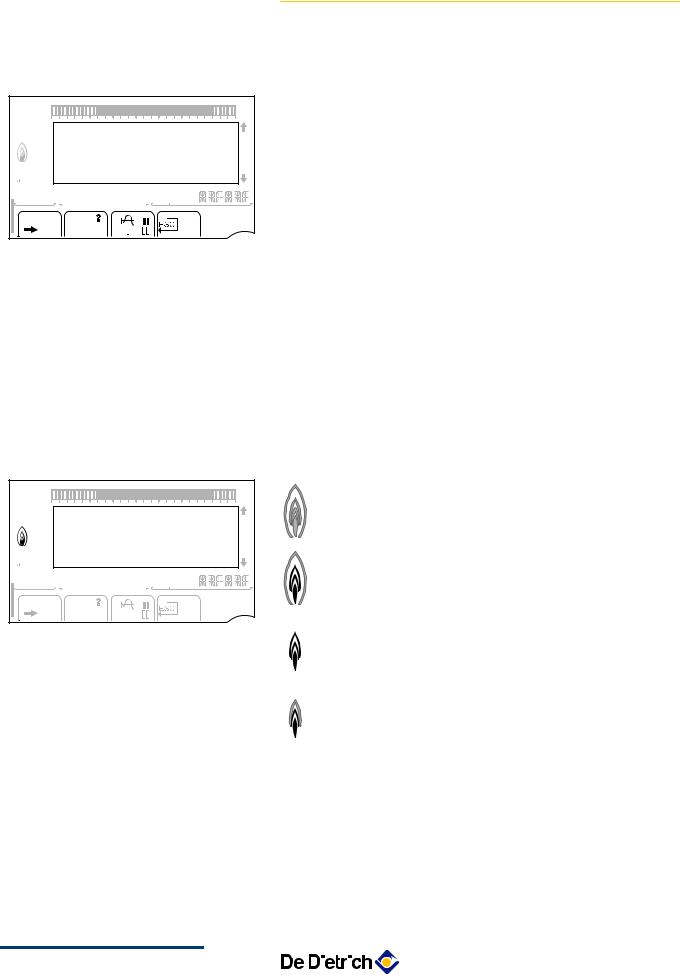
ATemperature setting key (heating, DHW, swimming pool)
B |
Operating mode selection key |
CDHW override key
DKey to access the parameters reserved for the installer
EKeysonwhichthefunctionvariesasandwhenselections are made
FRotary setting button:
4 Turn the rotary button to scroll through the menus or modify a value
4 Press the rotary button to access the selected menu or confirm a value modification
09/01/2014 - 300026440-001-03 |
|
|
|
10 |
|
|
3. Description |
AFC 18 - AFC 24 - AFC 30 |
3.3.2.Description of the display
n Key functions
|
|
|
|
|
|
|
|
|
|
|
|
|
|
> |
|
0 |
2 |
4 |
6 |
8 |
10 |
12 |
14 |
16 |
18 |
20 |
22 |
24 |
|
|
|
|
|
|
|
|
|
|
|
|
|
|
|
( |
|
|
|
|
|
|
|
|
|
|
|
|
|
|
’ |
BAR |
r |
|
|
|
|
|
|
|
|
|
|
|
|
? |
|
|
|
|
|
|
|
|
|
|
|
|
|
||
|
pb AUTOxc g m rjL |
|
|
A |
f |
|||||||||
|
|
|
|
|
|
|
|
|
|
|
|
|
- |
|
|
( |
|
|
' STD |
|
|
|
t |
|
|
C002696 |
STD |
||
|
|
|
|
|
|
|
|
|
|
|
|
|
|
b |
|
|
|
|
|
|
|
|
|
|
|
|
|
|
v |
|
|
|
|
|
|
|
|
|
|
|
|
|
|
j |
|
|
|
|
|
|
|
|
|
|
|
|
|
|
ESC |
|
|
|
|
|
|
|
|
|
|
|
|
|
|
t |
Access to the various menus
Used to scroll through the menus
Used to scroll through the parameters
The symbol is displayed when help is available
Used to display the curve of the parameter selected
Reset of the time programmes
Selection of comfort mode or selection of the days to be programmed
Selection of reduced mode or deselection of the days to be programmed
Back to the previous level
Back to the previous level without saving the modifications made
Manual reset
n Flame output level
0 |
2 |
4 |
6 |
8 |
10 |
12 |
14 |
16 |
18 |
20 |
22 |
24 |
|
|
|
|
|
|
|
|
|
|
|
|
|
|
C002705-A |
BAR |
|
|
|
|
|
|
|
|
|
|
|
|
|
pb AUTOxc g m |
rjM |
|
|
|
-A |
||||||||
|
|
C002701-B |
C002704 |
||||||||||
|
|
|
|
|
STD |
|
|
|
t |
|
|
||
|
|
|
|
|
|
|
|
|
|
|
|
||
|
|
|
|
|
|
|
|
|
|
|
|
|
C002703-A |
The whole symbol flashes: The burner starts up but the flame is not yet present
Part of the symbol flashes: Output is increasing
Steady symbol: The required output has been reached
Part of the symbol flashes: Output is dropping
C002702-A
11 |
|
|
|
09/01/2014 - 300026440-001-03 |
|
|
AFC 18 - AFC 24 - AFC 30 |
3. Description |
n Solar (If connected)
|
|
|
|
|
|
|
|
|
|
|
|
|
u |
0 |
2 |
4 |
6 |
8 |
10 |
12 |
14 |
16 |
18 |
20 |
22 |
24 |
|
|
|
|
|
|
|
|
|
|
|
|
|
|
L000200-A |
|
|
|
|
|
|
|
|
|
|
|
|
|
-A |
BAR |
|
|
|
|
|
|
|
|
|
|
|
|
L000201 |
pb AUTOxc g m |
rjM |
|
|
|
|||||||||
|
|
-A |
|
||||||||||
|
|
|
|
|
STD |
|
|
|
t |
|
|
L000197 |
L000198-A |
|
|
|
|
|
|
|
|
|
|
|
|
||
|
|
|
|
|
|
|
|
|
|
|
|
|
L000199-A |
The solar load pump is running
The top part of the tank is reheated to the tank set point
The entire tank is reheated to the tank set point
The entire tank is reheated to the solar tank set point
The tank is not loaded - Presence of the solar control system
n Operating modes
|
|
|
|
|
|
|
|
|
|
|
|
p |
0 |
2 |
4 |
6 |
8 |
10 |
12 |
14 |
16 |
18 |
20 |
22 |
24 |
|
|
|
|
|
|
|
|
|
|
|
|
b |
BAR |
|
|
|
|
|
|
|
|
|
|
|
|
pb AUTOxc g m rjM |
|
|
B |
|||||||||
|
|
|
|
|
STD |
|
|
|
t |
|
|
C002697- |
|
|
|
|
|
|
|
|
|
|
|
||
|
|
|
|
|
|
|
|
|
|
|
|
AUTO |
0 |
2 |
4 |
6 |
8 |
10 |
12 |
14 |
16 |
18 |
20 |
22 |
24 |
|
|
|
|
|
|
|
|
|
|
|
|
x |
BAR |
|
|
|
|
|
|
|
|
|
|
|
|
pb AUTOxc g m rjM |
|
|
B |
|||||||||
|
|
|
|
|
STD |
|
|
|
t |
|
|
C002698- |
|
|
|
|
|
|
|
|
|
|
m |
||
|
|
|
|
|
|
|
|
|
|
|
|
|
|
|
|
|
|
|
|
|
|
|
|
|
g |
|
|
|
|
|
|
|
|
|
|
|
|
m |
Summer mode: The heating is off. Domestic hot water continues to be produced
WINTER mode: Heating and domestic hot water working
Operation in automatic mode according to the timer programme
Comfort mode: The symbol is displayed when a DAY override (comfort) is activated
4Flashing symbol: Temporary override
4Steady symbol: Permanent override
Reduced mode: The symbol is displayed when a NIGHT override (reduced) is activated
4Flashing symbol: Temporary override
4Steady symbol: Permanent override
Holidaymode:ThesymbolisdisplayedwhenaHOLIDAY override (antifreeze) is activated
4Flashing symbol: Holiday mode programmed
4Steady symbol: Holiday mode active
Manual mode: The boiler operates with the displayed set point. All of the pumps operate. The 3-way valves are not controlled.
09/01/2014 - 300026440-001-03 |
|
|
|
12 |
|
|
3. Description |
AFC 18 - AFC 24 - AFC 30 |
n System pressure
|
|
|
|
|
|
|
|
|
|
|
|
bar |
0 |
2 |
4 |
6 |
8 |
10 |
12 |
14 |
16 |
18 |
20 |
22 |
24 |
BAR |
|
|
|
|
|
|
|
|
|
|
|
|
pb AUTOxc g m |
rjM |
|
|
l |
||||||||
|
|
A |
||||||||||
|
|
|
|
|
STD |
|
|
|
t |
|
|
C002708- |
|
|
|
|
|
|
|
|
|
|
|
||
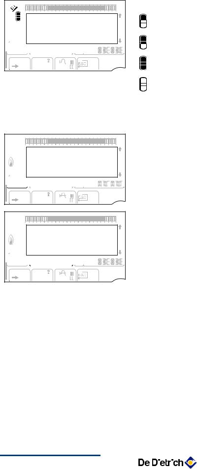
Pressureindicator:Thesymbolisdisplayedwhenawater pressure sensor is connected.
4Flashing symbol: The water pressure is insufficient.
4Steady symbol: The water pressure is sufficient.
Water pressure level
4R: 0,9 to 1,1 bar
4E: 1,2 to 1,5 bar
4Z: 1,6 to 1,9 bar
4A: 2,0 to 2,3 bar
4l: > 2,4 bar
n Domestic Hot Water override
0 |
2 |
4 |
6 |
8 |
10 |
12 |
14 |
16 |
18 |
20 |
22 |
24 |
BAR |
|
|
|
|
|
|
|
|
|
|
|
|
pb AUTOxc g m rjM |
|
|
A |
|||||||||
|
|
|
|
|
STD |
|
|
|
t |
|
|
C002707- |
|
|
|
|
|
|
|
|
|
|
|
||
A bar is displayed when a DHW override is activated:
4Flashing bar: Temporary override
4Steady bar: Permanent override
|
|
|
|
|
|
|
|
|
|
|
|
|
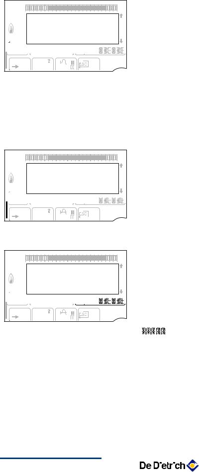
n Other information |
||
|
|
|
|
|
|
|
|
|
|
|
|
|
r |
The symbol is displayed when domestic hot water |
|
0 |
2 |
4 |
6 |
8 |
10 |
12 |
14 |
16 |
18 |
20 |
22 |
24 |
|
production is running. |
|
|
|
|
|
|
|
|
|
|
|
|
|
|
w |
Valve indicator: The symbol is displayed when a 3-way |
|
|
|
|
|
|
|
|
|
|
|
|
|
|
|
valve is connected. |
|
BAR |
|
|
|
|
|
|
|
|
|
|
|
|
|
|
|
pb AUTOxc g m |
rjM |
|
|
|
|
4 |
x: 3-way valve opens |
||||||||
|
|
B |
|
4 |
c: 3-way valve closes |
||||||||||
|
|
|
|
|
|
|
|
|
|
|
|
- |
|
||
|
|
|
|
|
STD |
|
|
|
t |
|
|
C002699 |
M |
The symbol is displayed when the pump is operating. |
|
|
|
|
|
|
|
|
|
|
|
|
|||||
|
|
|
|
|
|
|
|
|
|
|
|
|
|
Name of the circuit for which the parameters are |
|
|
|
|
|
|
|
|
|
|
|
|
|
|
|
displayed. |
|
13 |
|
|
|
09/01/2014 - 300026440-001-03 |
|
|
 Loading...