


DTP-21C6
Daewoo DTP-21C6, DTP-21V6, DTP-21V4, DTP-21V2, DTP-21V1 Service Manual
...
Service Guide
Colour Television
CHASSIS : CP-005
Model :
DTP-14V1/V2/V3/V5/C3/C4/C5TF
20V1/V3/C4/C5TF
21V1/V2/V4/V6/C6TF
S/G No. : CP005P-010G1
14/20/21 V1
14 V5
14/21 V2
14 C3
14/20 V3
14/20 C4
21 V4
14/20 C5
21 C6
If you need further information ( IC, Circuit descriptions or troubleshooting . . .)
about this model, Please visit our web site.( http://svc.dwe.co.kr)
Specifications
ITEM
ITEMS
CCIR STANDARD
COLOR STANDARD
POWER INPUT
POWER CONSUMPTION
TUNING SYSTEM
RECEPTION CHANNEL
SOUND OUTPUT
SPEAKER
ANTENNA INPUT
IMPEDANCE
AUXILIARY TETMINAL
REMOTE CONTROL
SPECIAL FUNCTION
DTP-14V1TF
DTP-14V2TF
DTP-14V3TF
DTP-14V5TF
DTP-14C3TF
DTP-14C4TF
DTP-14C5TF
57 W
Frequency Synthesizer (FS) Tuning System
BAND I : CH2 - CH4
BAND II : CH5 - CH12
CABLE BAND : S1' - S3', S1 - S20
HYPER BAND : S21 - S41
BAND IV, V : CH21 - CH69 (CH 70 for Italy)
INPUT : RCA JACK (Front)
SCART JACK (Rear)
DTP-20V1TF
DTP-20V3TF
DTP-20C4TF
DTP-20C5TF
BG, D/K, I/I, H, L/L'
PAL / SECAM / NTSC(AV only)
AC 230V, 50Hz
70 W
3 W
3 W 8 ohm
75 ohm Unbalanced
R-40A01
14 - Language OSD
With TELETEXT
Wake-up On Time
Sleep Timer
DTP-21V1TF
DTP-21V2TF
DTP-21V4TF
DTP-21V6TF
DTP-21C6TF
73 W
COMMOM
REMARKS
DAEWOO ELECTRONICS CO., LTD
http : //svc.dwe.co.kr
April. 2000
Important Service Notes
1. X-ray Radiation Rrecaution
1) Excessive high voltage can produce potentially hazardous X-RAY RADIATION. To avoid such hazards, the high voltage must not be above the specified limit. The nominal value of the high voltage of this receiver is
25.5kv(20”/21”) & 23.5kv(14”)at zero beam current (minimum brightness)
under a 120V/220V AC power source. The high voltage must not, under any
circumstances, exceed 28kv(20”/21”) & 26kv(14”). Each time a receiver
requires servicing, the high voltage should be checked following the HIGH
VOLTAGE CHECK procedure on page 10 of this manual. It is recommended as a parts of the service record. It is important to use an accurate
and reliable high voltage meter.
2) This receiver is equipped with X-RADIATION PROTECTION circuit which
prevents the receiver from producing an excessively high voltage even if the
B+voltage increases abnormally. Each time the receiver is serviced, XRADIATION PROTECTION circuit must be checked to determine that the
circuit is properly functioning, following the X-RADIATION PROTECTION
CIRCUIT CHECK procedure on page 6 of this manual.
3) The only source of X-RAY RADIATION in this TV receiver is the picture tube.
For continued X-RAY RADIATION protection, the replacement tube must be
exactly the same type tube as specified in the parts list.
4) Some parts in this receiver have special safety-related characteristics for XRAY RADIATION protection. For continued safety, parts replacement
should be undertaken only after referring to the PRODUCT SAFETY
NOTICE below.
2. Safety Precaution
WARNING: Service should not be attempted by anyone unfamiliar with the
necessary precaution on this receiver. The following are the necessary precaution to be observed before servicing.
1) Since the chassis of this receiver has hazardous potential to ground whenever the receiver is plugged in (floating chassis), an isolation transformer
must be used during servicing to avoid shock hazard.
2) Always discharge the picture tube anode to the CRT conductive coating the
picture tube. The picture tube is highly evacuated and if broken, glass fragments will be violently expelled. Use shatterproof goggles and keep picture
tube away from the body while handling.
3) When placing chassis in the cabinet, always be certain that all the protective
devices are put back in place, such as; nonmetallic control knobs, insulating covers, shields, isolation resistor-capacitor network, etc.
4) Before returning the set to the customer, always perform an AC leakage current check on the exposed metallic parts of the cabinet, such as antennas,
terminals, screw-heads, metal overlays, control shafts etc. to be sure the set
is safe to operate without danger of electrical shock. Plug the AC line cord
directly into a 120V AC outlet (do not use a line isolation transformer during
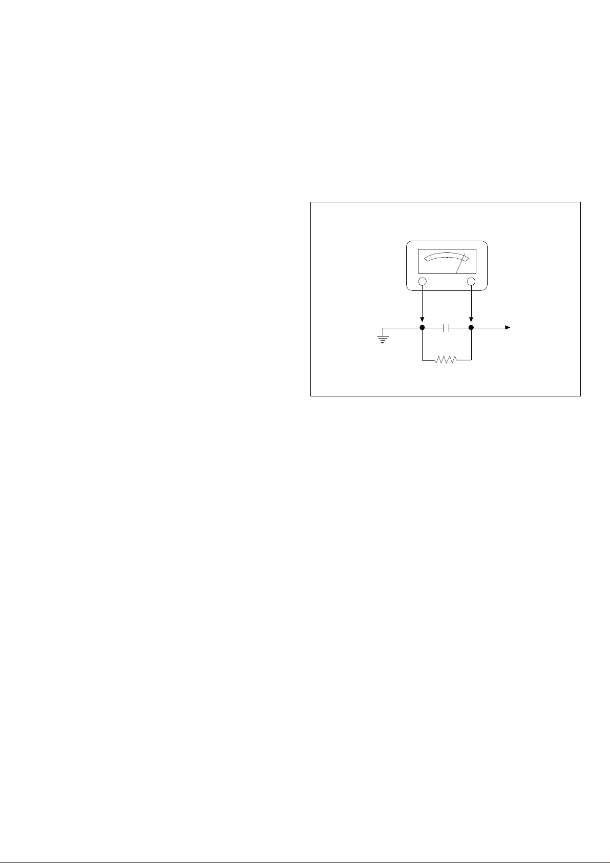
this check). Use an AC voltmeter having 5000 ohms per volt or more sensitivi-ty in the following manner.
Connect at 1500 ohm 10 watt resistor, paralleled by a 0.15 mfd. AC type
capacitor, between a known good earth ground (water pipe, conduit etc.)
and the exposed metallic parts, one at a time. Measure the AC voltage
across the combination of 1500 ohm resistor and 0.15 mfd capacitor. Voltage measured must not exceed 0.3 volts RMS. This corresponds to 0.2 millliamp. AC. Any value exceeding the limit constitutes a potential shock
hazard and must be corrected immediately.
AC VOLT METER
0.15uF
Good earth ground
such as d water
pipe, conduit, etc.
1500 OHM
10WATT
Place this probe
on each exposed
metallic part.
3. Product Safety Notice
Many electrical and mechanical parts in this chassis have special safety-related
characteristics. These characteristics are often passed unnoticed by a visual
inspection and the protection afforded by them cannot necessarily be obtained
by using replacement components rated for higher voltage, wattage, etc.
Replacement parts which have these special safety characteristics are identified in this manual and its supplements; electrical components having such features are identified by shading on the schematic diagram and the parts list.
Before replacing any of these components, read the parts list in this manual
carefully. The use of substitute replacement parts which do not have the same
safety characteristics as specified in the parts list may create X-ray radiation or
other hazards.
4. Service Notes
1) When replacing parts or circuit boards, clamp or bend the lead wires to terminals before soldering.
2) When replacing a high wattage resistor (metal oxide film resistor) in the circuit board, keep the resistor min 1/2 inch away form circuit board.
3) Keep wires away from high voltage or high temperature components.
DAEWOO ELECTRONICS CO., LTD.
C.P.OBOX8003 SEOUL, KOREA
Tel : 82-2-360-7798
Fax : 82-2-360-7877
E-mail : G7F00E@dwe.web.co.kr
Printed in Apr. 2000
Alignment Instructions
SVC v0
R BIAS
G BIAS
B BIAS
R DRIVE
G DRIVE
B DRIVE
V. CENTER
V. SIZE
H. CENTER
VCO
VCO FIN
VCO-L
VCO-L FIN
AGC
LED EAST
Pr
159
136
127
35
31
32
10
23
28
07
107
05
113
NO
44
01
ENTER SERVICE MODE
1. Select the Pr 91.
2. Adjust “ Sparpness “ to 0.
3. Enter the service mode
using the follow keys.
R G MENU.
2. SCREEN
1) Receive the Retma pattern and heat run over 15minutes.
2) Adjust the “R, G BIAS, R, G DRIVE” to 0, “B BIAS” to
127, “B DRIVE” to 32.
Adjust the screen volume that the Retma pattern reachs
the cut-off point.
3. WHITE BALANCE
1) Receive the Full white pattern and heat run over
15minutes.
2) Adjust the picture control at the point “X” value of white
balance instrument in 20cd/m
3) Enter the service mode.
4) Adjust “R BIAS, G BIAS” to x=288, y=301.
5) In order to exit the service mode power off the TV set and
power on.
6) Set the TV set to “Normal I” mode(20/21 inch) or set to
“Normal II” mode(14 inch)
7) Enter the service mode.
8) Adjust “R DRIVE, G DRIVE” to x=288, y=301.
9) Repeat above process until the white balance value to
x=288, y=301, X=20, x=288, y=301, X=200
(approximate) in 2) -8).
1. AFT
1) Set a signal Generator with
- RF FREQUENCY = 38.9MHz, 34.2MHz (L’)
- RF OUTPUT LEVEL = 80+/-5dBuV
- System = PAL for 38.9MHz.
SECAM-I for 43.2MHz.
2) Connect the Signal Generator RF Output
(PAL 38.9MHz) to P101 (Tuner IF Output).
There must be no signal input to the tuner.
3) Locate the cusor to “VCO” in Service Mode Menu,
then press the “Vol +” key and wait until the
“Please wait” disappear on the TV screen.
4) Connect the Signal Generator RF Output
(SECAM-L 34.2MHz) to P101 (Tuner IF Output).
5) Locate the cusor to “VCO-L” in Service Mode Menu,
then press the “Vol +” key and wait until the
“Please wait” disappear on the TV screen.
4. FOCUS
1) Apply a RETMA PATTERN signal.
2) Adjust the Focus Volume on FBT to obtain optimal
resolution.
5. AGC
1) Set a pattern Generator with
- RF LEVEL = 60dBuV
- 100% FULL COLOR BAR
2) Connect the Pattern Genetator RF Output to tuner
RF input.
3) Connect the probe of oscilloscope in AGC pin of tuner.
4) Adjust the AGC point to MAX - 1V.
( Simple Method )
1) Receive the pattern.
2) Locate the cusor in “AGC” and adjust using the
“VOL +” or “VOL -” keys.
3) Adjust the point there is no noise in about 60dBuV and no
beat in about 90dBuV.
 Loading...