


 Loading...
User Manual

|
Table of Contents |
TABLE OF CONTENTS |
|
1. Before You Begin ......................................................................................... |
1 |
What Is Included ...................................................................................................... |
1 |
Unpacking Instructions............................................................................................. |
1 |
Claims ............................................................................................................................ |
1 |
Text Conventions ..................................................................................................... |
1 |
Symbols ................................................................................................................... |
1 |
Disclaimer ................................................................................................................ |
1 |
Intellectual Property ................................................................................................. |
1 |
Safety Notes............................................................................................................. |
2 |
2. Introduction................................................................................................... |
3 |
Product Overview..................................................................................................... |
3 |
Product Dimensions................................................................................................. |
3 |
3. Setup.............................................................................................................. |
4 |
AC Power................................................................................................................. |
4 |
Fuse Replacement......................................................................................................... |
4 |
Power Linking................................................................................................................. |
4 |
Mounting .................................................................................................................. |
5 |
Orientation...................................................................................................................... |
5 |
Rigging........................................................................................................................... |
5 |
4. Operation....................................................................................................... |
6 |
Control Panel Operation........................................................................................... |
6 |
Menu Map ................................................................................................................ |
6 |
Configuration (DMX) ................................................................................................ |
7 |
Starting Address............................................................................................................. |
7 |
DMX Personalities.......................................................................................................... |
7 |
DMX Channel Assignments and Values .................................................................. |
7 |
Gobos............................................................................................................................. |
7 |
16CH.............................................................................................................................. |
8 |
10CH.............................................................................................................................. |
11 |
Configuration (Standalone) ...................................................................................... |
13 |
Automatic Programs....................................................................................................... |
13 |
Sound-Active Mode........................................................................................................ |
13 |
Sound Sensitivity ............................................................................................................ |
13 |
Manual Mode ................................................................................................................. |
13 |
Configuration (Settings) ........................................................................................... |
14 |
Pan Reverse .................................................................................................................. |
14 |
Tilt Reverse.................................................................................................................... |
14 |
Screen Reverse ............................................................................................................. |
14 |
Pan Angle....................................................................................................................... |
14 |
Tilt Angle ........................................................................................................................ |
14 |
Totem Mode................................................................................................................... |
14 |
Indicator ......................................................................................................................... |
15 |
Flash if DMX................................................................................................................... |
15 |
Reset.............................................................................................................................. |
15 |
Factory Reset................................................................................................................. |
15 |
System Information ........................................................................................................ |
15 |
IRC-6 Infrared Remote Control ................................................................................ |
16 |
IRC-6 Operation............................................................................................................. |
16 |
Master/Slave Mode .................................................................................................. |
17 |
Zero Adjust Mode..................................................................................................... |
17 |
Changing Gobos ...................................................................................................... |
18 |
5. Maintenance.................................................................................................. |
19 |
Product Maintenance ............................................................................................... |
19 |
6. Technical Specifications.............................................................................. |
20 |
Returns.............................................................................................................. |
21 |
Contact Us......................................................................................................... |
22 |
Intimidator Spot 475Z User Manual Rev. 2
Before You Begin
1. Before You Begin
What Is Included
• |
Intimidator Spot 475Z |
• |
Hanging Bracket |
• |
Power Cord |
• |
Quick Reference Guide |
Unpacking Instructions
Carefully unpack the product immediately and check the container to make sure all the parts are in the package and are in good condition.
Claims
If the box or the contents (the product and included accessories) appear damaged from shipping, or show signs of mishandling, notify the carrier immediately, not Chauvet. Failure to report damage to the carrier immediately may invalidate your claim. In addition, keep the box and contents for inspection.
For other issues, such as missing components or parts, damage not related to shipping, or concealed damage, file a claim with Chauvet within 7 days of delivery.
Text Conventions
Convention |
Meaning |
1–512 |
A range of values |
50/60 |
A set of values of which only one can be chosen |
Settings |
A menu option not to be modified |
<ENTER> |
A key to be pressed on the product’s control panel |
ON |
A value to be entered or selected |
Symbols
Symbol Meaning
Critical installation, configuration, or operation information. Not following these instructions may make the product not work, cause damage to the product, or cause harm to the operator.
Important installation or configuration information. The product may not function correctly if this information is not used.
Useful information.
Disclaimer
Chauvet believes that the information contained in this manual is accurate in all respects. However, Chauvet assumes no responsibility and specifically disclaims any and all liability to any party for any loss, damage or disruption caused by any errors or omissions in this document, whether such errors or omissions result from negligence, accident or any other cause. Chauvet reserves the right to revise the content of this document without any obligation to notify any person or company of such revision, however, Chauvet has no obligation to make, and does not commit to make, any such revisions. Download the latest version from www.chauvetdj.com.
Intellectual Property
The works of authorship contained in this manual, including, but not limited to, all design, text and images are owned by Chauvet.
© Copyright 2019 Chauvet & Sons, LLC. All rights reserved.
Electronically published by Chauvet in the United States of America.
CHAUVET, the Chauvet logo, and Intimidator Spot 475Z are registered trademarks or trademarks of Chauvet & Sons LLC (d/b/a Chauvet and Chauvet Lighting) in the United States and other countries. Other company and product names and logos referred to herein may be trademarks of their respective companies.
Intimidator Spot 475Z User Manual Rev. 2 |
Page 1 of 22 |

Before You Begin
Safety Notes
•This product is not intended for permanent installation.
•Always connect the product to a grounded circuit to avoid the risk of electrocution.
•Always disconnect the product from the power source before cleaning or replacing the fuse.
•Avoid direct eye exposure to the light source while the product is on.
•Make sure the power cord is not crimped or damaged.
• Never disconnect the product from power by pulling or tugging on the cord.
•If mounting the product overhead, always secure to a fastening device using a safety cable.
•Make sure there are no flammable materials close to the product when operating.
•Do not touch the product’s housing when operating because it may be very hot.
•The voltage of the outlet to which you are connecting this product must be within the range stated on the decal or rear panel of the product.
•The product is for indoor use only! (IP20) To prevent risk of fire or shock, do not expose the product to rain or moisture.
•Always install the product in a location with adequate ventilation, at least 20 in (50 cm) from adjacent surfaces.
•Be sure that no ventilation slots on the product’s housing are blocked.
• Never connect the product to a dimmer or rheostat.
• Make sure to replace the fuse with another of the same type and rating.
•Never carry the product from the power cord or any moving part. Always use the handles.
•The maximum ambient temperature is 104 °F (40 °C). Do not operate this product at higher temperatures.
•In the event of a serious operating problem, stop using the product immediately.
•Do not open this product. It contains no user-serviceable parts.
•To eliminate unnecessary wear and improve its lifespan, during periods of non-use completely disconnect the product from power via breaker or by unplugging it.
Keep this User Manual for future use. If the product is sold to someone else, be sure that they also receive this document.
Page 2 of 22 |
Intimidator Spot 475Z User Manual Rev. 2 |
Introduction
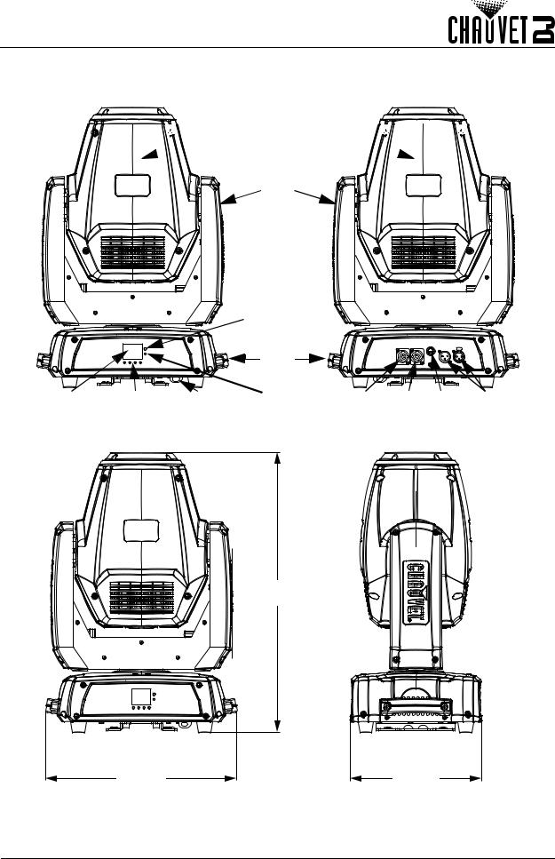
2. Introduction
Product Overview
Moving
 Head
Head 


Yoke
|
|
|
IR Sensor |
|
|
|
|
|
|
|
Carry |
|
|
|
|
|
|
|
Handles |
|
|
|
|
LED |
Menu |
Safety |
LED |
Power |
Power |
Fuse |
DMX |
Display |
Buttons |
Loop |
Indicator |
In |
Out |
Holder |
In/Out |
Product Dimensions
20.9 in
531 mm
14.3 in
363 mm
9.8 in
250 mm
Intimidator Spot 475Z User Manual Rev. 2 |
Page 3 of 22 |
Setup
3. Setup
AC Power
The Intimidator Spot 475Z has an auto-ranging power supply and it can work with an input voltage range of 100 to 240 VAC, 50/60 Hz.
To determine the product’s power requirements (circuit breaker, power outlet, and wiring), use the current value listed on the label affixed to the product’s back panel, or refer to the product’s specifications chart. The listed current rating indicates the product’s average current draw under normal conditions.
•Always connect the product to a protected circuit (a circuit breaker or fuse). Make sure the product has an appropriate electrical ground to avoid the risk of electrocution or fire.
• To eliminate unnecessary wear and improve its lifespan, during periods of non-use completely disconnect the product from power via breaker or by unplugging it.
Never connect the product to a rheostat (variable resistor) or dimmer circuit, even if the rheostat or dimmer channel serves only as a 0 to 100% switch.
Fuse Replacement
1.Disconnect the product from power.
2.Using a flat-head screwdriver, unscrew the fuse holder cap from the housing.
3.Remove the blown fuse.
4.Replace with a fuse of the same type and rating.
5.Screw the fuse holder cap back in place and reconnect power.
 Disconnect the product from the power outlet before replacing the fuse.
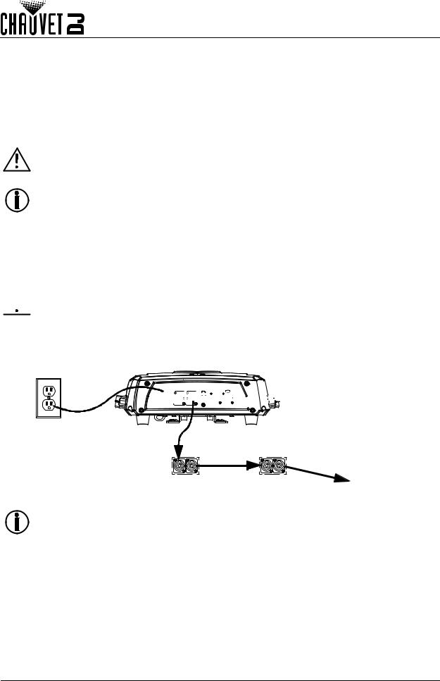
Power Linking
The product provides power linking via the outlet located in the back of the product. See the diagram below for further explanation.
Power Linking Diagram


 1st Product
Power
Source
2nd Product |
3rd Product |
Additional |
|
|
Products |
You can power link up to 3 Intimidator Spot 475Z products on 120 VAC or up to 5 Intimidator Spot 475Z products on 230 VAC.
Page 4 of 22 |
Intimidator Spot 475Z User Manual Rev. 2 |

Setup
Mounting
Before mounting the product, read and follow the safety recommendations indicated in the Safety Notes.
Orientation
The Intimidator Spot 475Z may be mounted in any position; however, make sure adequate ventilation is provided around the product.
Rigging
•Before deciding on a location, always make sure there is easy access to the product for maintenance and programming.
•Make sure adequate ventilation is provided around the product.
•Make sure that the structure or surface onto which you are mounting the product can support the product’s weight. (see the Technical Specifications)
•When mounting the product overhead, always use a safety cable. Mount the product securely to a rigging point, whether an elevated platform or a truss.
•When rigging the product onto a truss, use a mounting clamp of appropriate weight capacity.
•When power linking multiple products, mount the products close enough for power linking cables to reach.
•The rubber feet also serve as floor supports and allow for surface mounting. When mounting the product on the floor, make sure that the product and cables are away from people and vehicles.
Mounting Diagram


 Mounting Clamp
(such as CLP-15 from Chauvet)
Safety Cable 
(such as CH-05
from Chauvet)
 Mounting Bracket
 Feet for Floor
Mounting (x4)
When using one mounting clamp with this fixture, use a clamp with a captive bolt to prevent accidental loosening.
Intimidator Spot 475Z User Manual Rev. 2 |
Page 5 of 22 |

Operation
4. Operation
Control Panel Operation
To access the control panel functions, use the four buttons located underneath the display. Please refer to the Product Overview to see the button locations on the control panel.
Button Function
<MENU> Exits from the current menu or function
<UP> Navigates upwards through the menu list or increases a selected numeric value <DOWN> Navigates downwards through the menu list or decreases a selected numeric value <ENTER> Enables the currently displayed menu or sets a selected value into the selected function
Menu Map
|
|
|
|
|
|
Main Level |
Programming Levels |
Description |
|||
Address |
|
001–512 |
|
|
Sets the DMX starting address |
|
DMX |
|
16CH |
Selects the DMX mode |
|
|
|
10CH |
|||
|
|
|
|
||
|
Slave |
Slave1–4 |
Selects Slave mode 1, 2, 3, or 4 |
||
|
|
Auto |
|
|
Selects Auto mode |
|
|
Sound |
|
|
Selects Sound-Active mode |
|
|
IR |
|
|
Selects Infrared control mode |
|
|
Pan |
|
|
Manual pan control |
Run Mode |
|
Tilt |
|
|
Manual tilt control |
|
Color |
|
|
Manual color wheel control |
|
|
|
Gobo |
|
|
Manual rotating gobo wheel control |
|
Manual |
Gobo Rotate |
000–255 |
Manual gobo rotation control |
|
|
Gobo2 |
|
Manual static gobo wheel control |
||
|
|
Prism |
|
|
Manual prism control |
|
|
Focus |
|
|
Manual focus control |
|
|
Zoom |
|
|
Manual zoom control |
|
|
Dimmer |
|
|
Manual dimmer control |
|
|
Shutter |
|
|
Manual shutter control |
|
Pan Reverse |
|
OFF |
Normal pan operation |
|
|
|
ON |
Reverse pan operation |
||
|
|
|
|||
|
Tilt Reverse |
|
OFF |
Normal tilt operation |
|
|
|
ON |
Reverse tilt operation |
||
|
|
|
|||
|
Screen |
|
OFF |
Normal display |
|
|
Reverse |
|
|
|
|
|
|
ON |
Reverse display |
||
|
Pan Angle |
|
540 |
Selects the 540° pan angle range |
|
|
|
360 |
Selects the 360° pan angle range |
||
|
|
|
180 |
Selects the 180° pan angle range |
|
|
Tilt Angle |
|
270 |
Selects the 270° tilt angle range |
|
Setup |
|
180 |
Selects the 180° tilt angle range |
||
|
|
90 |
Selects the 90° tilt angle range |
||
|
|
|
|||
|
Totem Mode |
|
OFF |
Does not restrict the pan and tilt motion |
|
|
|
UP |
Restricts the pan and tilt motion for overhead mount |
||
|
|
DOWN |
Restricts the pan and tilt motion for floor mount |
||
|
Sensitivity |
001–100 |
Sets the sound sensitivity |
||
|
Indicator |
|
ON |
Enables/Disables LED indicator |
|
|
|
OFF |
|||
|
|
|
|
||
|
Flash if DMX |
|
ON |
Enables/Disables Flash if DMX |
|
|
|
OFF |
|||
|
|
|
|
||
|
|
Reset |
|
|
Resets the product |
|
|
Factory Set |
Loads factory defaults |
||
|
|
|
|
|
|
Page 6 of 22 |
|
|
|
|
Intimidator Spot 475Z User Manual Rev. 2 |
Loading...