

Page 1

INSTRUCTIONS FOR USE
I
Instructions for use
CONTENTS
1 - GENERAL 3
1.1 - GENERAL SAFETY REGULATIONS 3
1.1.1 - STANDARD SAFETY DEVICES 3
1.2 - FIELD OF APPLICATION 3
1.3 - MAIN PARTS 3
1.4 - OVERALL DIMENSIONS 3
1.5 - TECHNICAL DATA 4
2 - HANDLING AND LIFTING 4
3 - START - UP 5
3.1 - ELECTRICAL CONNECTION 5
3.2 - ADAPTER MOUNTING 5
3.3 - WHEEL MOUNTING 5
3.4 - WHEEL GUARD ASSEMBLY
4 - CONTROLS AND COMPONENTS 6
4.1 - CONTROL PANEL AND DISPLAY 6
4.2 - AUTOMATIC DISTANCE AND DIAMETER GAUGE 6
5 - USE OF THE WHEEL BALANCER 7
5.1 - DATA SETTING 7
5.2 - RESULT OF MEASUREMENT 8
5.2.1 - STATIC UNBALANCE 8
MODIFYING SET DIMENSIONS 8
5.2.2 -
5.2.3 - EXACT POSITIONING OF THE ADHESIVE WEIGHT BY MEANS OF THE GAUGE
WITH CLIPS
5.2.4 - SPLIT FUNCTION (HIDDEN ADHESIVE WEIGHTS) 10
5.2.5 - OPPOSITE POSITION 10
5.2.6 - UNBALANCE OPTIMIZATION 11
5.2.7 - AUTOMATIC MINIMIZATION OF STATIC UNBALANCE 11
6 - SET UP 12
6.1 - MENU 12
6.2.1 - RIM DISTANCE GAUGE 13
6.2.2 - DIAMETER GAUGEE40 M 13
6.3 - BALANCING MACHINE CALIBRATION 14
7 - ERRORS 15
7.1 - INCONSISTENT UNBALANCE READINGS 16
8 - ROUTINE MAINTENANCE (see exploded drawings) (for non specialized personnel only 16
8.1 - TO REPLACE THE FUSES 16
(OPTION) 5
9
I 0672 - 1
GB
Page 2

I 0672 - 2
GB
Page 3

1 - GENERAL
1. ► 1 - GENERAL SAFETY REGULATIONS
The machine should only be used by authorized and suitably trained personnel. ▪
Do not use the machine for purposes other than those specifi ed in this manual. ▪
The machine should not be modifi ed in any way except for those modifi cations explicitly carried out by ▪
specialised personnel.
Never remove the safety dehyvices. Any work on the machine should only be carried out by specialised ▪
personnel.
Carefully clean the coupling surfaces before performing any operation. ▪
Avoid using strong jets of compressed air for cleaning. ▪
Use alcohol to clean the plastic panel or shelves (AVOID LIQUIDS CONTAINING SOLVENTS). ▪
Before starting the wheel balancing cycle, make sure that the wheel is securely locked on the adapter. ▪
The machine operator should avoid wearing clothes with fl apping edges. Make sure that unauthorized ▪
personnel do not approach the machine during the work cycle.
Avoid placing objects inside the cabinet as they could impair the correct operation of the machine. ▪
1.1.1 - STANDARD SAFETY DEVICES
►
STOP push button for stopping the wheel under emergency conditions. ▪
The wheel guard is not compulsory since the balancing speed is less than 100 min ▪
-1.
1.2 - FIELD OF APPLICATION ►
The machine is designed for balancing wheels of cars, light commercial vehicles or motorcycles weighing less than 75
kg. It can be operated in a temperature range of 0° to + 45° C.
The following functions are provided: SPLIT; Unbalance optimisation; Autodiagnostics; Autocalibration.
1.3 - MAIN PARTS ►
PROTEZIONE
WHEEL GUARD
RUOTA
CONTROL PANEL
PANNELLO E
DISPLAY
AND DISPLAY
CALIBRO
AUTOMATIC GAUGE
AUTOMATICO
MANDRINO
SHAFT ASSEMBLY
1.4 - OVERALL DIMENSIONS ►
I 0672 - 3
GB
Page 4

1.5 - TECHNICAL DATA ►
Single-phase power supply 115 / 230 V 50/60 Hz
Protection class IP 54
Max.power consumption
Balancing speed 100 min
0,8 Kw
-1
Cycle time for wheel 4.7 sec. (5 3/4"x14") 15 Kg.
Balancing accuracy 1 gram
Position resolution ± 1.4 °
Average noise < 70dB (A)
Rim-machine distance 0 - 265 mm
Rim width setting range 1.5” ÷ 20” or 40 ÷ 510 mm
Diameter setting range 10” ÷ 30” or 265 ÷ 765 mm
2 - HANDLING AND LIFTING
TO LIFT THE MACHINE, LEVER ONLY ON THE BASE WHERE THE 3 SUPPORT POINTS ARE LOCATED.
N
EVER, UNDER ANY CIRCUSTANCE, APPLY FORCE TO OTHER POINTS SUCH AS THE SPINDLE, HEAD, OR ACCESSORY SHELF.
Check that the balancing machine touches the fl oor at the three support points. •
It functions properly without having to fasten it to the fl oor with wheels weighing up to 35 kg; for heavier •
wheels, fasten it at the points indicated.
U
N
E
M
OP
T
g
z
o
z
o
S
T
R
STA
T
U
L
A
T
S
LU
A
I 0672 - 4
GB
Page 5

3 - START - UP
3.1 - ELECTRICAL CONNECTION ►
HE ELECTRICAL CONNECTION MUST BE MADE BY SPECIALIZED PERSONNEL. CONNECTION TO THE SINGLE PHASE MAINS MUST
T
BE MADE BETWEEN PHASE AND NEUTRAL, AND NEVER, UNDERANY CIRCUMSTANCES, BETWEEN PHASE AND EARTH (GROUND).
E
FFICIENT EARTHING (GROUNDING) IS ESSENTIAL FOR CORRECT MACHINE OPERATION. THE MANUFACTURER DECLINES
RESPONSIBILITY AND WARRANTY IN THE EVENT OF INCORRECT CONNECTION.
ALL
Before connecting the machine to the mains through relative cable, check that the mains voltage matches the one
shown on the nameplate at the back of the balancing machine. Rating of the electrical connection should be on the
basis of the machine electrical power consumption (see nameplate).
The machine mains supply cable should be fi tted with a plug conforming to current regulations. ▪
It is recommended to provide the machine with its own electrical connection through a slow acting safety switch ▪
rated at 4 A (230 V) or 8 A (115 V).
When connection is made directly to the main control panel without using any plug, it is advisable to padlock the ▪
main switch of the balancing machine in order to limit its use to authorized personnel only.
3.2 - ADAPTER MOUNTING ►
The wheel balancer is supplied complete with cone ►
type adapter for fastening wheels with central bore.
The threaded terminal is fi tted according to the dra
wing; it can be removed to fi t optional adapters.
It can be removed to fi t optional adapters.
3. ► 3 - WHEEL MOUNTING
The wheels should be fastened with one of the numerous adapters manufactured by the manufacturer (see enclosed
brochures). Incorrect centering inevitably causes unbalance.
3.4 - WHEEL GUARD ASSEMBLY ► (option)
Fasten the components to the base as illustrated in the specifi c exploded drawing1.
The positions of these guards can be adjusted using the special screws accessed from inside the main support2.
With th3. e guard closed check that the microswitch prod has slipped into place on the ring; to this end, adjust the
angular position of the control ring if necessary.
I 0672 - 5
GB
Page 6

4 - CONTROLS AND COMPONENTS
4.1 - CONTROL PANEL AND DISPLAY ►
1
2
18
9
8
13
1-2 Digital readouts, AMOUNT OF UNBALANCE, inside/outside
3-4 Digital readouts, POSITION OF UNBALANCE, inside/outside
5 Inside correction mode selection button
6 Indicators, correction mode selected
7 Outside correction mode selection button
8 Special function indicators
9 Manual WIDTH/DISTANCE/DIAMETER setting buttons and MENU selection
10 Push button, FUNCTION MENU
11 Balancing cycle stop button
12 Balancing cycle start button
13
14 Push button, SPLIT (unbalance resolution)
15 MENU selection confi rmation pushbutton
16 Push button, unbalance reading < 5 g (.25 oz)
17 Unbalance optimization selection pushbutton
18 Grams/ounces selection pushbutton
3
5
6
Position repeater push button
7
8
4
17
14
10
15
16
11
12
ON ▪ LY USE THE FINGERS TO PRESS THE PUSH BUTTONS.
N
EVER USE THE COUNTERWEIGHT PINCERS OR OTHER POINTED OBJECTS. ▪
4.2 - ► AUTOMATIC DISTANCE AND DIAMETER GAUGE
Allows measuring the distance from the machine and the diameter at the point of application of the counterweight.
The same gauge allows proper positioning of the counterweights inside using the specifi c function.
I 0672 - 6
GB
Page 7

5 - USE OF THE WHEEL BALANCER
5.1 - DATA SETTING ►
The balancing data is set by means of an "intelligent" automatic gauge; confi rmation of the measurement and the
position appear on the display. The round part of the gauge must rest on the rim where the weight will be positioned.
a b
While the gauge is moving the following appears
when the measurement has been stored
a) standard weights: When only one measurement is made, the machine interprets the presence of a rim with clip-
on weight correction
The width value (b) must be set with the buttons
measured with the compass gauge provided.
b) adhesive weights: Make two successive measurements on two correction planes inside the rim.
The balancing machine automatically interprets that the correction will be made with adhesive weights and
the following appears:
. The correct measurement is that which can be
b
;
.
For a different combination of the type or position of the weights on the rim, use the button
.
I 0672 - 7
GB
Page 8

5.2 - RESULT OF MEASUREMENT ►
Inside correction Outside correction
After performing a balancing spin, the amounts of unbalance are shown on the digital readouts.
Digital readouts with LED lit up indicate the correct angular wheel position to mount the counterweights (12 o’clock
on).
positi
If the unbalance is less than the threshold selected, 0 is displayed instead of the unbalance; with it is possible
to read the values below the threshold chosen.
Note : in the case of wheels with a diameter less than or equal to 13” and at temperature conditions near
0°, the wheel balancer automatically inserts a special measuring cycle composed of two
successive measurements. The accuracy of the unbalance values and the reliability of the wheel
balancer remain unchanged. This type of operation is reset each time the wheel balancer is started.
5.2.1 - STATIC UNBALANCE ►
It is selected by pressing and is shown on the central display. The position is indicated on the displays 3 and 4.
5.2.2 - ► MODIFYING SET DIMENSIONS
If the wheel dimensions have been entered incorrectly, the parameters can be modifi ed without repeating the balan-
cing spin by pressing :
access parameter modifi cation →
(select
→ to obtain the new measurement
pull out the gauge to repeat the measurement
to modify: (a) distance, (b) width, (d) diameter
or:
→ to obtain the new measurement.
I 0672 - 8
GB
Page 9

5 ► .2.3 - EXACT POSITIONING OF THE ADHESIVE WEIGHT BY MEANS OF THE GAUGE WITH CLIPS
- Press the button if using the correction method with weights on the inside of the rim
▪ Fit the correction weight in the specifi c gauge seat with the
adhesive part facing upwards
▪ Bring the wheel into correct angular position for the plane to be
corrected.
▪ Pull the gauge further outwards.
▪ Return the gauge to the rest position.
▪ INSIDE CORRECTION POSITION
▪ OUTSIDE CORRECTION POSITION
▪ When the weight application distance has been reached a
beep is sounded (can be deactivated).
▪ rotate the gauge until the correction weight adheres to the rim
▪ the fact that the weight application position is no longer vertical
FI
FE
(see fi gure) is automatically compensated
▪ to cancel this function, press
button again.
I 0672 - 9
GB
Page 10

5.2.4 - SPLIT FUNCTION (HIDDE ► N ADHESIVE WEIGHTS)
The SPLIT function is used to position the adhesive weights behind the wheel spokes so that they are not visible.
This function should be used in ALU mode where the adhesive weight is applied on the outside. Input the wheel
dimensions and do a spin.
2
1
▪ Turn the wheel to the outside unbalance correction position
as indicated by the machine
1
2
2
1
▪ Position one spoke at 12 o'clock (e.g. 1) and press
▪ Following the rotation direction indicated on the display,
1
2
2
1
position spoke 2 at 12 o'clock and press
▪ Position the wheel as indicated by the LEDs.
The unbalance is indicated on the right-hand display
▪ Repeat the operation for the other spoke
To return to normal unbalance display, press any button.
NOTE: The distance between the spokes must be at least 18° and at most 120° (if not, the errors 24,25
or 26 appear).Spokes with irregular or inconstant angles can be compensated.
5.2.5 ► - OPPOSITE POSITION
The normal balancing condition requires the correction weight to be applied at the top (12 o’clock) when the symbol
is displayed:
Apply the correction weight at the top (12 o’clock)
If OPPOSITE POSITION is enabled, the eventual application position for the bottom weight is also indicated next to
the positioning arrows to facilitate cleaning the rim and the relative application of adhesive weights. The symbol used
is:
Apply the correction weight at the bottom (6 o’clock)
I 0672 - 10
GB
Page 11

5.2.6 - UNBALANCE OPTIMIZATION ►
This function serves to reduce the amount of weight to be added in order to balance the wheel ▪
It is suitable for static unbalance exceeding 30 g. ▪
This operation is required if no unbalance has been measured previously; otherwise go to the next step
Mar ▪ k with chalk a reference point on the adapter and rim
With the aid of a tyre changer
, turn the rim on the tyre by 180° ▪
Refi t the wheel with the reference mark coinciding between rim and adapter ▪
RH di ▪ splay: percentage reduction
LH display: actual static unbalance which can be reduced by matching ▪
TYRE
POSITION
Mark the two positions of the rim and tyre, and turn the rim on the tyre until ▪
the positions correspond in order to obtain the optimization results shown on
the display.
RIM
POSITION
CANCEL OPTIMISATION IN ANY PHASE.
5.2.7 - AUTOMATIC MINIMIZATION OF STATIC UNBALANCE
►
Initial unbalance
ssxx
ddxx
gg gg
residual static
With conventional
44 gg
wheel balancer
ssxx
phase shift
Possible approximations
ssxx
residual static
ddxx
gg gg
33 gg
ddxx
gg gg
5500°°
ssxx
residual static
Choice with minimum
static residual
ddxx
gg gg
11 gg 66 gg
ssxx
gg gg
residual static
This program is designed to improve the quality of
balancing without any mental effort or loss of time by
the operator. In fact by using the normal commercially
available weights, with pitch of 5 in every 5 g, and by
applying the two counterweights which a conventional
wheel balancer rounds to the nearest value, there
could be a residual static unbalance of up to 4 g.
ddxx
The damage of such approximation is emphasized
by the fact that static unbalance is cause of most
of disturbances on the vehicle. This new function,
resident in the machine, automatically indicates
the optimum entity of the weights to be applied by
approximating them in an “intelligent” way according
to their position in order to minimize residual static
unbalance.
I 0672 - 11
GB
Page 12
6 - SET UP
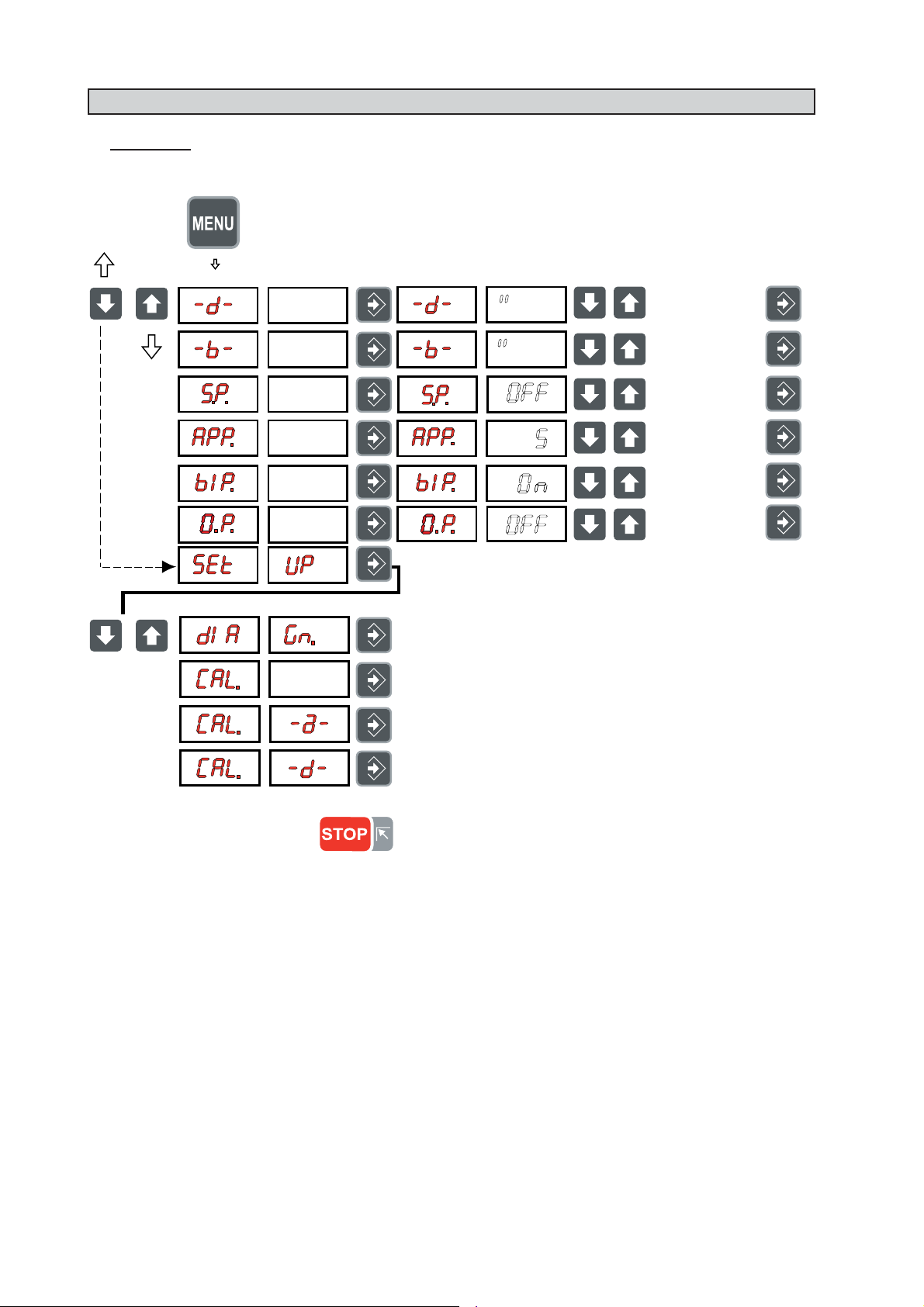
6.1 - MENU ►
diameter unit of
measure mm/inch
width unit of
measure mm/inch
start from
guard closing
approximates
1-5g 0.1-0.25oz
acoustic signal
activation on/off
on/off
opposite position
See chapter on AUTODIAGNOSTICS
See chapter on BALANCING MACHINE CALIBRATION
Calibration of automatic RIM DISTANCE gauge
Calibration of automatic DIAMETER gauge
RETURN TO MEASUREMENT SCREEN
I 0672 - 12
GB
Page 13
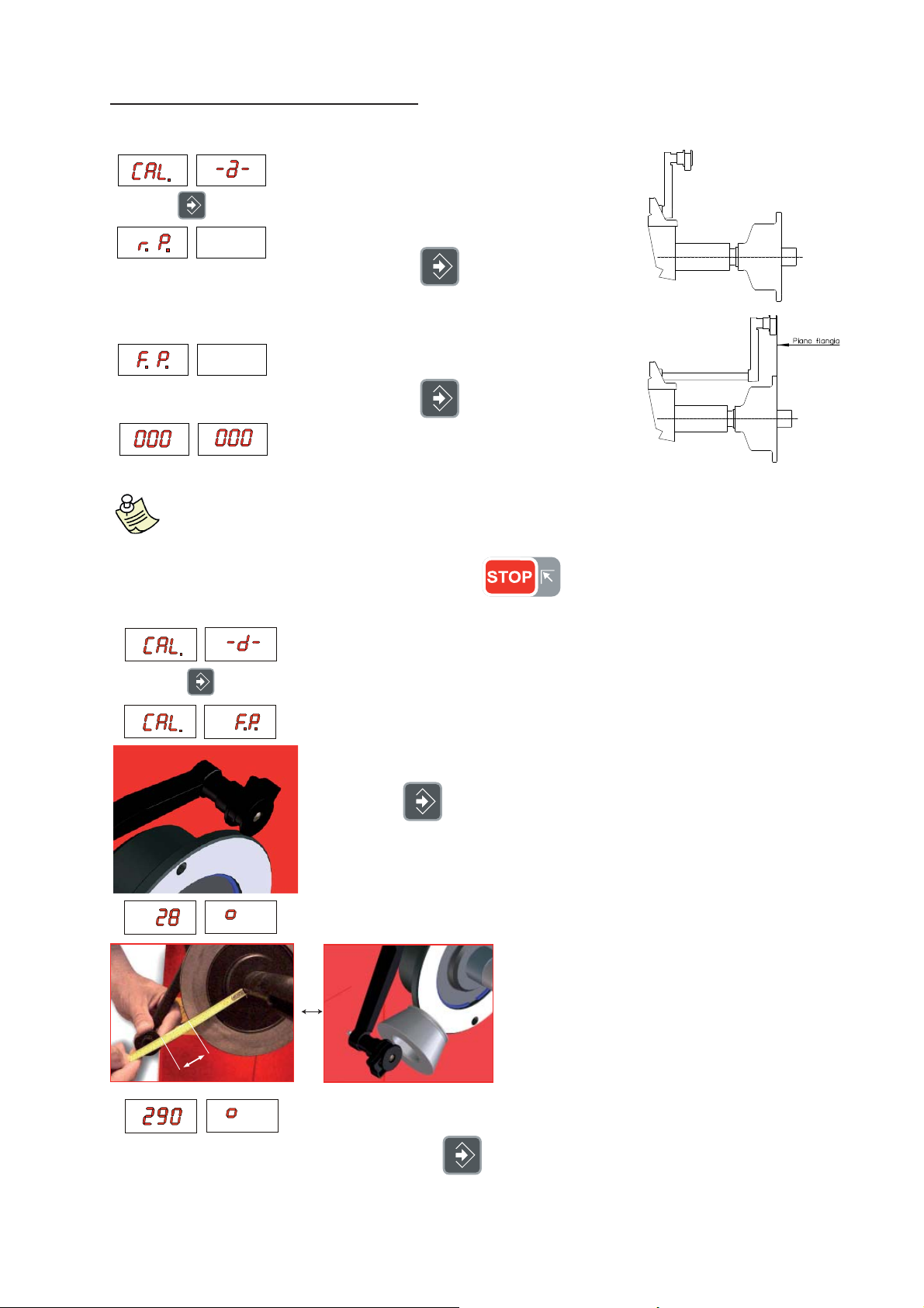
6.2 - AUTOMATIC GAUGES CALIBRATION
6.2.1 - RIM DISTANCE GAUGE ►
►
►
Leave the distance gauge in rest position ▪
and press
Pull out the gauge up to the adapter fl ange ▪
and press
C ▪ ORRECT CALIBRATION
Return the gauge to rest position.
The wheel balancer is ready for operation.
N.B.: In the event of errors or faulty operation, the writing
gauge to the rest position and repeat the calibration operation exactly as described above. If the
error persists, contact the Technical Service Department. In the event of incorrect input in the rim
distance gauge calibration function, press
6.2.2 - DIAMETER GAUGE
► E40 m
►
►
“r.P .”: appears on the display : shift the
to cancel it.
m ►
Plac ▪ e the round part of the gauge terminal on the fl ange as shown in the fi gure
and press
The number 28 ± 3° appears on the left display . ▪
Turn the gauge downward position the ▪
round part of the gauge terminal at 40 mm
(radial distance) from the fl ange as indicated
in the fi gure; alternatively use one of the cones
provided as shown in the images
40 m
m
The nu ▪ mber 290 ± 3° should appear on the left display. The calibration is
already correct.
If not, press the ▪
appears on the left display.
Return the gauge to rest position. ▪
button holding the gauge still at 40 mm: the number 290
I 0672 - 13
GB
Page 14

6.3 - BALANCING MACHINE CALIBRATION ►
To calibrate the machine, operate as follows:
Fit a medium-sized wheel with steel rim on the shaft. Example: 6” x 15” (± 1”) best with less then 20 g unbalance ▪
Take the exact measurements of the wheel mounted as described in ▪
RESETTING OF INCORRECT DIMENSIONS WOULD MEAN THAT THE MACHINE IS NOT CORRECTLY CALIBRATED, THEREFORE
P
ALL SUBSEQUENT MEASUREMENTS WILL BE INCORRECT UNTIL A NEW SELF-CALIBRATION IS PERFORMED WITH THE CORRECT
DIMENSIONS!
Perform a manual spin under normal conditions ▪
Add a sample weight on the outside in any angular position. ▪
DATA SETTING.
Shift the sample weight from the outside to the inside keeping the same angu ▪
lar position.
Turn the wheel until the sample weight is in the 12 o’clock position ▪
END OF CALIBRATION ▪
CANCELS CALIBRATION IN ANY PHASE. ▪
I 0672 - 14
GB
Page 15

7 - ERRORS
During machine operation, various causes of faulty operation could occur. If detected by the microprocessor , they appear
on the display as follows:
ERRORS CAUSES CONTROLS
Black The wheel balancer does not turn on. 1. Check proper connection to the mains.
Err. 1 No rotation signal. 1. Check in self-diagnostics that the encoder functions properly
Err. 2 Too low speed during measurement.
Err. 3 Too high unbalance. 1. Check the wheel dimension setting.
Err. 4 Rotation in opposite direction.
Err. 5 Guard open
Err. 7 /
Err. 8 /
Err. 9
Err. 11 Too high speed error.
Err.14/
Err.15/
Err.16/
Err.17/
Err. 18/
Err. 19
Err.20 Wheel at standstill. The wheel is at a
Err.21 Motor on for more than 15 seconds. 1. Check in self-diagnostics that the encoder functions properly
Err.22 Maximum number of spins possible for
Err. 24 Distance between the spokes less than
Err. 25 Distance between the spokes greater
During the unbalance measurement
revolutions, the wheel speed has fallen to
below 42 rpm.
After pressing [START], the wheel
starts turning in the opposite direction
(anticlockwise).
The [START] pushbutton was pressed
without fi rst closing the guard.
NOVRAM parameter read error 1. Repeat machine calibration
The average spinning speed is more than
240 rpm.
Unbalance measurement error. 1. Check in self-diagnostics that the encoder functions properly
standstill for more than one second after
START.
the unbalance measurement has been
exceeded.
18 degrees.
than 120 degrees.
2. Check and if necessary replace the fuses on the power board.
3. Replace the computer board.
2. Replace the rotation sensor.
3. Replace the computer board.
1. Check that a vehicle wheel has been mounted on the wheel
balancer.
2. Check in self-diagnostics that the encoder functions properly
3. Replace the computer board.
2. Check the sensor connections.
3. Run the machine calibration function.
4. Mount a wheel with a more or less known unbalance (less than 100
grams) and check the machine response.
5. Replace the computer board.
1. Check in self-diagnostics that the encoder functions properly
2. Check the bearing/spring of the phase generator
1. Reset the error.
2. Close the guard.
3. Verify the function of the protection switch.
4. Press the [START] button.
2. Shut down the machine.
3. Wait for at least ~ 1 min.
4. Restart the machine and check proper functioning.
5. Replace the computer board.
1. Check in self-diagnostics that the encoder functions properly
2. Replace the computer board.
2. Check the sensor connections.
3. Check the machine earthing connection.
4. Mount a wheel with a more or less known unbalance (less than 100
grams) and check the machine response.
5. Replace the computer board.
1. Check in self-diagnostics that the encoder functions properly
2. Check the connections on the power board.
3. Replace the computer board.
2. Check the connections on the power board.
3. Replace the computer board.
1. Check that a vehicle wheel has been mounted on the wheel
balancer.
2. Check in self-diagnostics that the encoder functions properly
3. Replace the computer board.
The minimum distance between the spokes where the 1.
unbalance is to be split must be greater than 18 degrees.
Repeat the SPLIT function increasing the distance between 2.
the spokes.
The maximum distance between the spokes where the 1.
unbalance is to be split must be less than 120 degrees.
2. Repeat the split function increasing the distance between the
spokes.
I 0672 - 15
GB
Page 16

Err. 26 First spoke too far from the unbalance The maximum 1. distance between the unbalance position and
the spoke must be less than 120 degrees.
Repeat the split function increasing the distance between the2.
spokes and the unbalance.
7.1 - INCONSISTENT UNBALANCE READINGS ►
Sometimes after balancing a wheel and removing it from the balancing machine, it is found that, mounting it on the
machine again, the wheel is not balanced.
This does not depend on incorrect indication of the machine, but only on faulty mounting of the wheel on the adapter
i.e. in the two mountings the wheel has assumed a different position with respect to the balancing machine shaft centre
line. If the wheel has been mounted on the adapter with screws, it could be possible that the screws have not been
correctly tightened, i.e. crosswise one by one, or else (as often occurs) holes have been drilled on the wheel with too
wide tolerances. Small errors, up to 10 grams (0.4 oz) are to be considered normal in wheels locked by a cone; the error
is normally greater for wheels fastened with screws.
If, after balancing, the wheel is found to be still out-of-balance when refi tted on the vehicle, this could be due to unba-
lance of the car brake drum or very often due to the holes for the screws on the rim and drum sometimes drilled with
too wide tolerances.
In such case a readjustment could be advisable using the balancing machine with the wheel mounted on the car.
8 - ROUTINE MAINTENANCE (see exploded drawings) (for non specialized personnel only
Always disconnect the machine from the mains before carrying out any operation.
,
8.1 - TO REPLACE THE FUSES ►
Remove the weight holder shelf to gain access to the power supply board where the fuses are located. If fuses
require replacement, use ones of the same current rating. If the fault persists, contact Technical Service.
NONE OF THE OTHER MACHINE PARTS REQUIRE MAINTENANCE.
I 0672 - 16
GB
 Loading...