


SF8500
SF-8500(LX-575)
AUG. 1993
R
(without price)
INDEX

CONTENTS
1. SCHEMATIC DIAGRAM................................................................................................ 1
2. SPECIFICATIONS ......................................................................................................... 5
3. TO REPLACE THE BATTERY...................................................................................... 6
4. ERROR MESSAGE ....................................................................................................... 7
5. TO RESET THE DIGITAL DIARY ................................................................................. 7
6. TO SAVE THE DATA TO OTHER MACHINE............................................................... 8
7. TO CHECK THE MEMORY CAPACITY...................................................................... 11
8. DISASSEMBLY ........................................................................................................... 12
9. BLOCK DIAGRAM ...................................................................................................... 14
10. CIRCUIT EXPLANATIONS
10-1. System chart................................................................................................. 15
10-2. Power supply circuit .................................................................................... 16
10-3. CPU pin description (HD62076C02)............................................................ 21
10-4. Gate array pin descriptions (
µPD65005GC-566-3B6)................................ 22
10-5. Power supply chip IC pin descriptions (SC371015FU) ............................. 22
10-6. Character generator ROM pin descriptions (HD62063B01) ..................... 23
10-7. Operation program ROM pin descriptions (
µPD23C4001EBGW-304)..... 24
10-8. RAM pin descriptions (M5M51008AFP-10LL) ............................................ 24
11. DIAGNOSTIC OPERATION ........................................................................................ 25
12. TROUBLESHOOTING................................................................................................. 30
13. PARTS LIST ................................................................................................................ 33
14. PCB VIEW ................................................................................................................... 35
15. ASSEMBLY VIEW....................................................................................................... 37

— 1 —
1. SCHEMATIC DIAGRAM
1-1. Main PCB
— 2 —
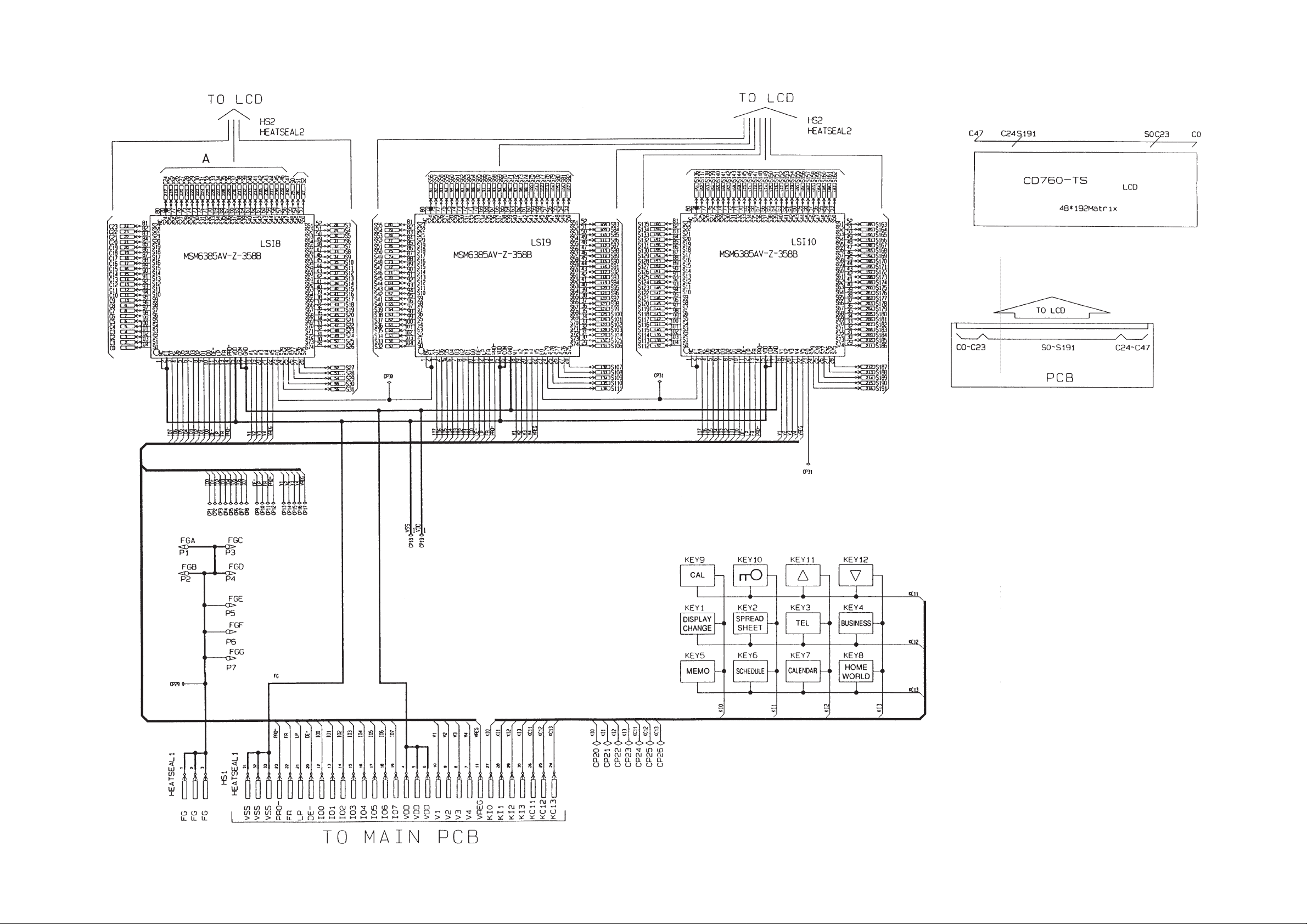
1-2. Display PCB
— 3 —
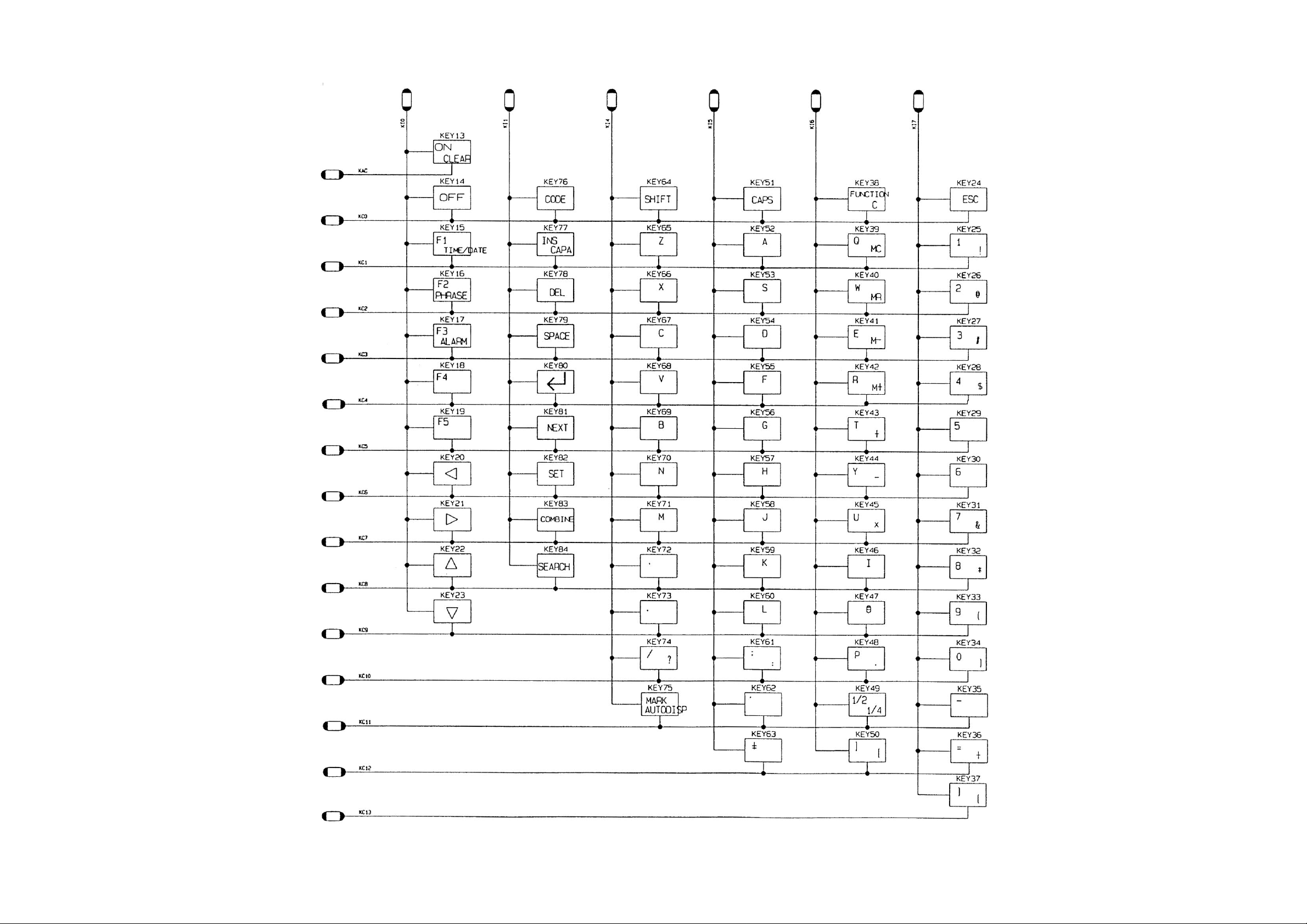
1-3. Key Matrix
— 5 —
2. SPECIFICATIONS
Data storage:
Telephone/business card/memo/schedule data storage/recall, calendar display, marker, phrase memory,
secret area, editing, capacity display, auto display
Clock:
Average of accuracy ±3 seconds per day under normal temperatures; worldtime, schedule alarm, daily
alarm
Calculation:
12-digit arithmetic calculations, constants for + / – / × / ÷ , independent memory, percentages, square roots,
24-digit approximations, date calculations, other mixed calculations
General:
Display element: 32-column × 6-line LCD
Memory capacity: 64 KB (65,499 bytes) for the Spreadsheet Mode data plus
64 KB (51,910 bytes) for other mode's data
Main component: LSI
Power supply: Main Power Supply — Two CR2032 lithium batteries
Backup Power Supply — One CR2032 lithium battery
Power consumption: 0.05W
Battery life: Main: Approximately 120 hours (Repeated cycle of 1-minute data input
into Telephone Directory followed by 10-minute display. Operation
temperature of 20°C)
Approximately 150 hours (Continuous display in Telephone Direc-
tory. Operation temperature of 20°C)
Backup: 5 years if main batteries are replaced as soon as they become weak.
1 year if dead main batteries are left in the unit.
• Note That the life of the battery that comes with the unit starts when the
battery is loaded in the unit at the factory. The life you get from the battery may
be shorter than normal because of the time the unit spends in transport, on
the shelf, etc.
Auto power off: Approximately 6 minutes after last key operation
Operating temperature: 0°C ~ 40°C (32°F ~ 104°F)
Dimensions: Unfolded: 10.5H × 154W × 155.2mmD (
3
/8"H × 6"W × 6
1
/8"D)
Folded: 17.9H × 154W × 78mmD (
3
/4"H × 6"W × 3
1
/16"D)
Weight: 152.5g (5.4 oz) including batteries
Current consumption:
Power switch TYP. [µA] MAX [µA]
OFF 8 29
ON 1,447 13,258
ON (Operating) 6,707 19,958
— 6 —
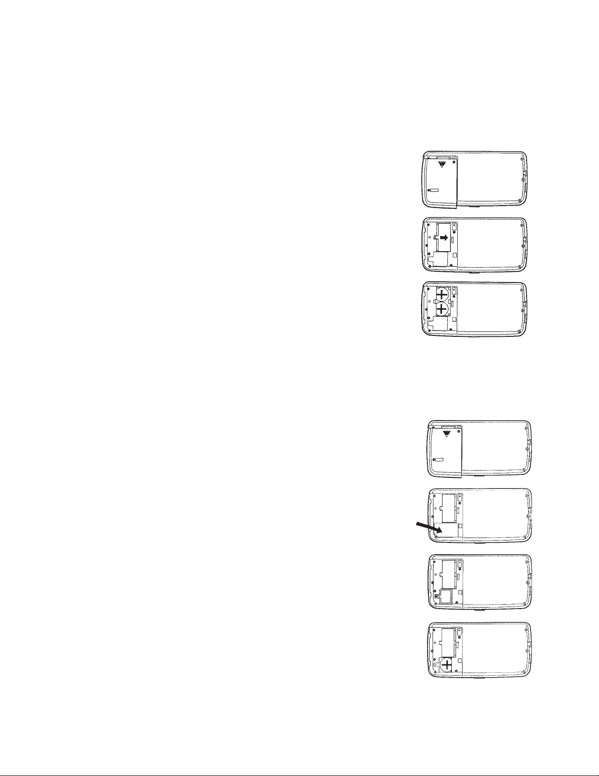
3. TO REPLACE THE BATTERY
A) To replace the main batteries
Before replacing the main batteries, note the following precautions.
•Do not remove the back-up battery from the SF Unit while main batteries are removed.
• Be sure to replace both batteries at the same time, and do not use an old battery with a new
one.
1. Remove the screw that hold the battery compartment cover in
place.
2. Remove the battery compartment cover by sliding it in the
direction indicated by the arrow in the illustration.
3. Slide the main battery holder in the direction indicated by the
arrow.
4. Remove both old batteries and replace with two new ones.
• Use two new batteries. Wipe the surfaces of the batteries with a
soft, dry cloth. Make sure that the positive (+) sides of the
batteries are facing up (so you can view the positive sides as the
batteries lie in the battery compartment).
5. Replace the battery holder.
6. Replace the battery compartment cover and fasten it in place
using the screw.
B) To replace the back-up battery
Before replacing the back-up battery, note the following precautions:
• Do not remove the main batteries from the SF Unit while back-up battery is removed.
• Be sure to replace the back-up battery at least once a year.
1. Remove the screw that hold the battery compartment cover in
place.
2. Remove the battery compartment cover by sliding it in the
direction indicated by the arrow in the illustration.
3. First , remove this sticker from the back-up battery holder.
4. After removing this sticker, take the screw off that secures the
back-up battery holder in place, and then remove the battery
holder.
5. Remove the old battery and replace it with a new one.
• Wipe the surfaces of the battery with a soft, dry cloth.
Make sure that the positive (+) side of the battery is facing up (so
you can view the positive side as the battery lies in the battery
compartment.)
6. Replace the back-up battery holder and fasten it in place using
the screw, and replace the sticker over the battery holder.
7. Replace the battery compartment cover and fasten it in place
using the screw.
— 7 —
Message Meaning Action
DATA ITEM NOT Text specified for Correct or change
FOUND! search does not exist. specified text.
PASSWORD Wrong password Enter correct
MISMATCH! entered. password.
MEMORY FULL! No more room in Delete unnecessary
memory for storage of data items from
data. memory.
DATA ERROR! Abnormal data caused Consult the "DATA
CONSULT YOUR by strong impact, static ERROR" section on
OWNER'S MANUAL electricity, etc. page 2 of owner's
UNDER "DATA manual.
ERROR"
4. ERROR MESSAGE
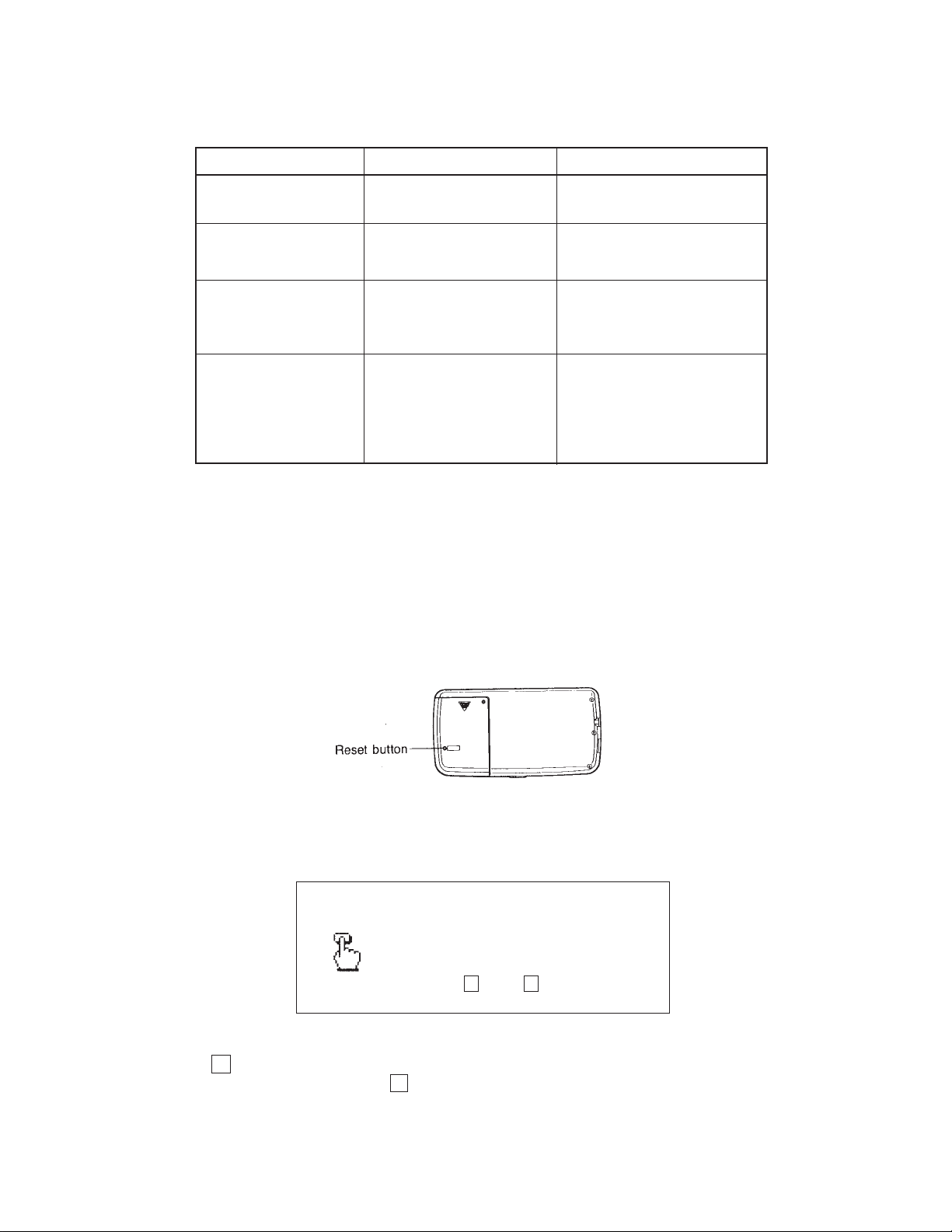
5. TO RESET THE DIGITAL DIARY
Before describing the RESET operation, a note of WARNING —
The following procedure will erase
all data stored in memory, including marked data items. Be sure to perform the RESET operation
only if you wish to clear all data.
To reset the SF Unit's memory
1. Switch on power and press the RESET button with a thin, pointed object.
The following message appears on the display.
DELETE ALL DATA ITEMS
STORED IN MEMORY ?
YES Y / NO N
2. Press Y to reset the SF Unit and clear everything from its memory. To abort the procedure
without clearing anything, press N .
— 8 —
Following the RESET operation, the Home Time Display appears. The initial settings of the SF Unit after
reset are shown below.
HOME TIME: Washington D.C.
JAN/1/1994 (SAT)
12:00 AM
12-hour format
WORLD TIME: New York
Daily Alarm: 12:00 PM
Sound: Schedule alarm ON
Daily alarm OFF
Key ON
Character input:CAPS
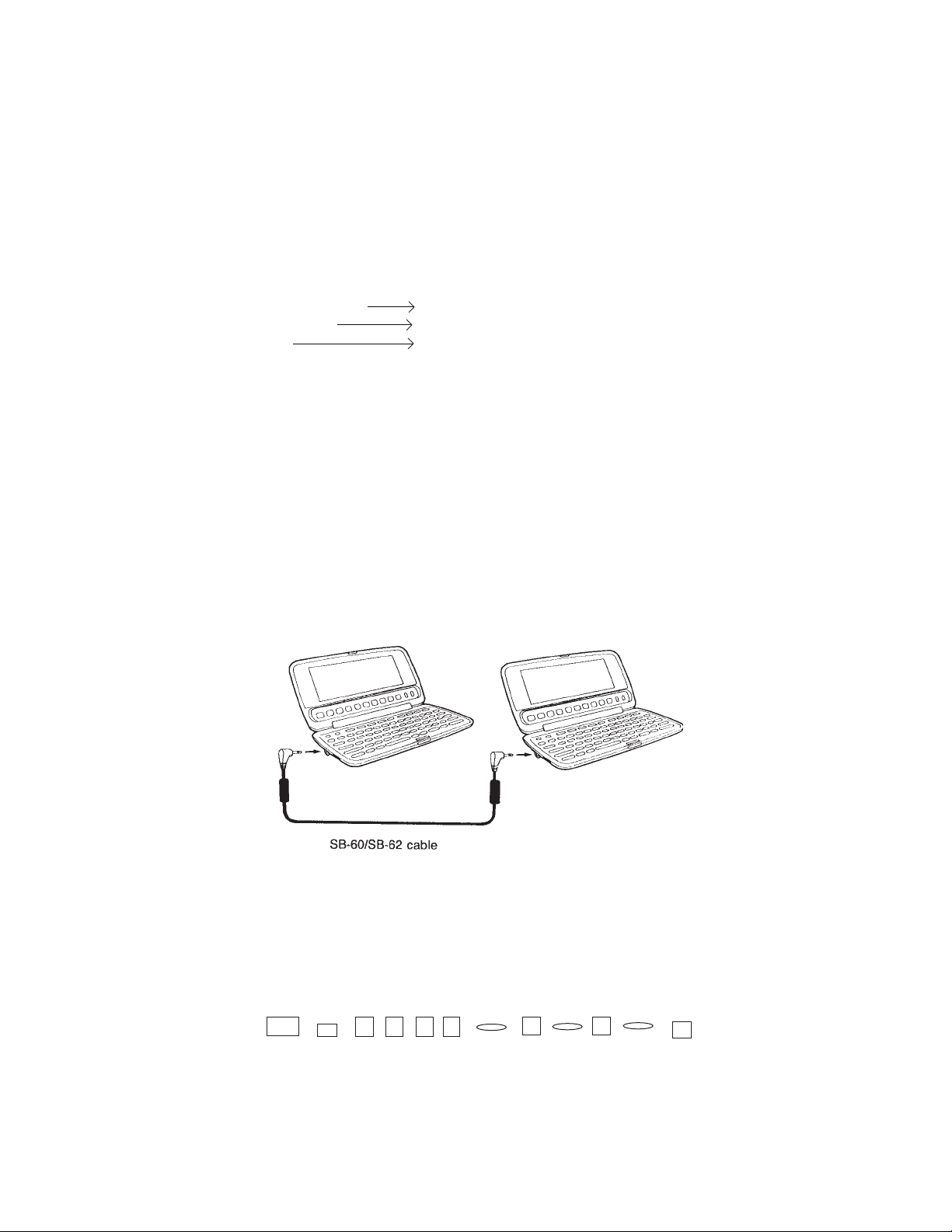
6. TO SAVE THE DATA TO OTHER MACHINE
SF-8500 can transfer customers data to other SF-8500 with memory protection only when replacing the
LCD or the outer case. How to transfer the data.
* Before connecting the cable (SB-60 or SB-62), be sure to reset the slave machine to clear all
data.
1) Turn off the power switch and connect the two units using the cable (SB-60 or SB-62) as shown in
the drawing.
ON
CLEAR/AC
CAL
2) Turn on the power switch of each machine.
3) The slave machine must be set the date of Feb. 3rd, 1901 into the memory under the calculator
mode.
Operation: 1 9 0 1 2 3
If you don't set the date, the "PASSWORD" isn't transferred to the slave machine.
DATE DATE
TIME TIME M+
R
DATE
TIME
— 9 —
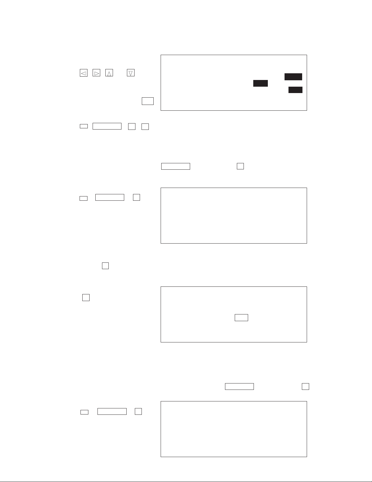
To change the hardware
parameters, press the
, , and
cursol keys.
HARDWARE PARAMETERS
PARITY EVEN ODD NONE
BIT LENGTH7 bits 7 bits 8 bits
BPS 1200 2400 4800 9600
TEL
2 Press to select "RECEIVE" and the following display appears to indicate that the slave
machine is ready to receive data.
1 SEND
2 RECEIVE
3 PRINT
4 HARDWARE PARAMETERS
5 DATA TO RAM CARD
6 PEN PRINTING
TEL
RECEIVE OK !
TO STOP, PRESS ESC
TEL
4) Check the hardware parameters, and if the units have another condition, reset as follows.
2
6) Set up the customer's machine.
1 While the transmitting unit is in the Calendar Display, Telephone Directory, Business Card
Library, Memo Mode, or Schedule Keeper, press the key followed by to select
"DATA COMMUNICATION", and the following menu appears.
FUNCTION
4
***
***
5) Set up the slave machine.
1 While in the Calendar Display, Telephone Directory, Business Card Library, Memo Mode, or
Schedule Keeper, press the key followed by to select " DATA COMMUNICA-
TION", and the following menu appears.
TEL
FUNCTION
4
4
TEL
FUNCTION
4
1 SEND
2 RECEIVE
3 PRINT
4 HARDWARE PARAMETERS
5 DATA TO RAM CARD
6 PEN PRINTING
TEL
2
TEL
FUNCTION
4 4
To set the hardware
parameters, press the set
key.
FUNCTION
— 10 —
1 ONE DATA ITEM
2 MODE DATA ITEMS
3 ALL DATA ITEMS
— SEND —
TEL
SEND ALL DATA ITEMS ?
YES SET / NO ESC
TEL
NOW SENDING !
TO STOP, PRESS ESC
3 Press to select "ALL DATA ITEMS", and the following display appears to confirm
whether you wish to proceed.
2 Press to select "TRANSMIT" and the following menu appears.
1
3
4 Press the key to proceed with the data transmission, or press if you wish to cancel.SET ESC
1
3
SET
TEL
Data are transmitted in the sequence of Telephone Directory data, Business Card Library data, Memo
data, Schedule Keeper data and Calendar data.
* If the customer's machine uses full memory, it takes about one minute and ten seconds for this
transferring.
* The following messages appear on the display of the receiving unit when a problem occurs during
data communications. All data transferred up to display of the message is retained in memory, but
data communication is terminated.
If one of the following error messages appear, press the , , , ,
, , , key, to clear the error message. Then, take corrective
action and try data communication again.
BUSINESS CARD
MEMO SCHEDULE
HOME TIME
WORLD TIME
CAL
CALENDAR
— 11 —
Message Cause
STOPPED ! • ESC key pressed on transmitting or receiving unit.
• Memory area of receiving unit full.
• Battery power drops below a certain level.
TRANSMIT ERROR ! Cable connection broken or abnormal noise in cable.
MEMORY FULL ! Memory area of receiving unit full.
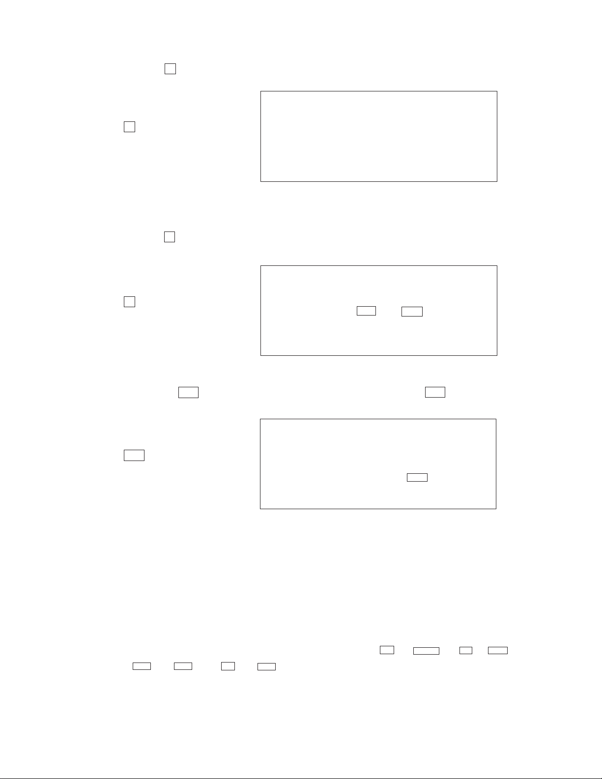
7. TO CHECK THE MEMORY CAPACITY
There are two types of Memory Capacity Display, as shown below:
SF UNIT: Total memory used for storage of Telephone Directory, Business Card Library,
Memo, Calendar, and Schedule Keeper data.
SPREADSHEET: Total memory used for storage of Spreadseet data.
Press the key and then press the key to check the current memory capacity.
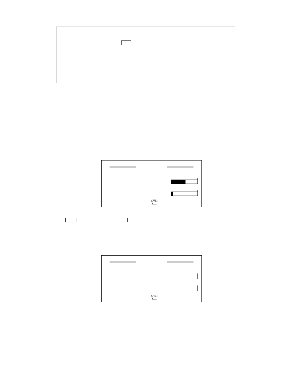
Following the memory reset operation, the display will appear as follows.
When the percentage of memory used reaches 100%, you will not be able to enter any more data into
memory.
SHIFT
CAPA
CAPACITY
SF UNIT
SPREADSHEET
60%
20565
16%
54520
FREE
FREE
Bytes
Bytes
0 10050
0 10050
CAPACITY
SF UNIT
SPREADSHEET
0%
51910
0%
64848
FREE
FREE
Bytes
Bytes
0 10050
0 10050
 Loading...