


(with price)
SF-4400(LX-594A)
SF-4600B(LX-594E/F)
JUN. 1994
SF-4400 |
SF-4600B |
|
|
|
|
|
|
|
R
|
|
CONTENTS |
|
1. |
SCHEMATIC DIAGRAM .................................................................................................... |
1 |
|
|
1-1. |
MAIN PCB .................................................................................................................. |
1 |
|
1-2. |
KEY MATRIX ............................................................................................................. |
2 |
2. |
SPECIFICATIONS ............................................................................................................. |
3 |
|
3. |
TO REPLACE THE BATTERIES ....................................................................................... |
5 |
|
4. |
DATA TRANSFER ............................................................................................................. |
6 |
|
5. |
OPERATION REFERENCE ............................................................................................. |
10 |
|
|
5-1. |
RESET OPERATION ............................................................................................... |
10 |
|
5-2. TO ADJUST THE DISPLAY CONTRAST ............................................................... |
11 |
|
|
5-3. TO CHECK THE MEMORY STATUS ...................................................................... |
11 |
|
|
5-4. |
THE SOUND MENU ................................................................................................. |
11 |
6. |
LSI, IC (Pin function) ...................................................................................................... |
12 |
|
|
6-1. |
CPU .......................................................................................................................... |
12 |
|
6-2. |
RAM:μPD43256G-101215LL (LSI2,LSI3) ............................................................... |
13 |
|
6-3. |
VOLTAGE REGULATOR:S-81253SGUP (REG1) .................................................. |
14 |
|
6-4. |
VOLTAGE DETECTOR:S-80752AN (DET1) ........................................................... |
14 |
7. |
TROUBLESHOOTING ..................................................................................................... |
15 |
|
8. |
HARD CHECK ................................................................................................................. |
18 |
|
9. |
ASSEMBLY VIEW ........................................................................................................... |
23 |
|
10. |
PARTS LIST .................................................................................................................... |
25 |
|

1.SCHEMATIC DIAGRAM
1-1. MAIN PCB
NOTE: 1. LSI4, R3, R11 are not mounted. 2. R1, R2 are not used.
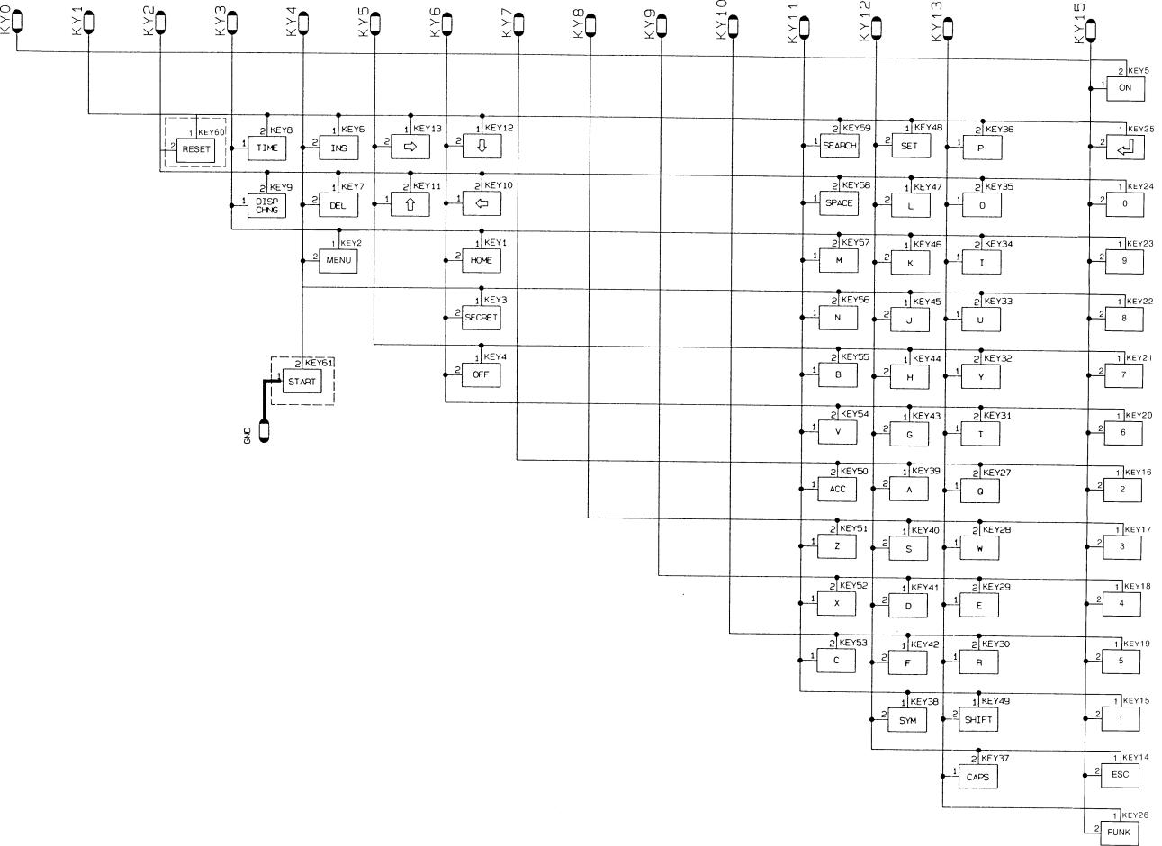
1-2. KEY MATRIX
— 2 —
2.SPECIFICATIONS
Data storage:
Storage and recall of telephone, memo, schedule, reminder data; calendar display; secret area; editing; memory status display.
Clock:
World time; reminder alarm; schedule alarm; daily alarm; accuracy under normal temperatures: ±3 seconds average.
Calculation:
10-digit arithmetic calculations; arithmetic constants (+, –, x, ÷); independent memory; percentages; square roots; 20-digit approximations; date calculations; other mixed calculations.
General: |
|
|
Display element: |
|
16-column x 4-line LCD |
Memory capacity: |
|
SF-4400: 32 KB (28579 bytes) |
|
|
SF-4600B: 64 KB (61347 bytes) |
Main component: |
|
LSI |
Power supply: |
|
2 lithium batteries (CR2032) |
Power consumption: |
0.05W |
|
Battery life: |
|
|
Approximately 450 hours continuous operation in Telephone Directory |
||
Approximately 380 hours repeating one minute of input and 10 minutes of display in Telephone |
||
Directory |
|
|
Approximately 12 months for memory backup |
||
Auto power off: |
|
Approximately 6 minutes after last key operation |
Operating temperature: 0°C ~ 40°C (32°F ~ 104°F) |
||
Dimensions: |
|
|
Unfolded: |
10.6H x 141W x 159.5Dmm (3/8"H x 5 1/2"W x 6 1/4"D) |
|
Folded: |
12.4H x 141W x 82Dmm (1/2"H x 5 1/2"W x 3 1/4"D) |
|
Weight: |
|
98.2g (3.5 oz) |
Current consumption:
Power switch |
TYP. [μA] |
MAX [μA] |
|
|
|
OFF |
5.15 |
10.0 |
|
|
|
ON |
256 |
420 |
|
|
|
Storage Capacity:
The 64K bytes memory capacity (32K bytes for SF-4400) includes a 61347 bytes user area (28579 bytes for SF-4400). The following shows examples of what this means for the storage of data in each mode.
Telephone Directory:
Approximately 2920 (1360 for SF-4400), under the following conditions: 8-character name
10-character telephone number
— 3 —
Approximately 1460 (680 for SF-4400), under the following conditions: 8-character name
10-character telephone number
20-character address
Memo:
Approximately 2780 (1290 for SF-4400), 20-character memos.
Schedule Keeper:
Approximately 1910 (890 for SF-4400), under the following conditions: 1 item per day, 20 characters per item
30 days per month
Starting time specified, alarm time set
Approximately 2190 (1020 for SF-4400), under the following conditions: 1 item per day, 20 characters per item
30 days per month
Starting time specified, no alarm time
Reminder:
Approximately 3600 (1680 for SF-4400), under the following conditions:
10 characters per item Alarm time set
Approximately 4080 (1900 for SF-4400), under the following conditions:
10 characters per item No alarm time
— 4 —
3.TO REPLACE THE BATTERIES
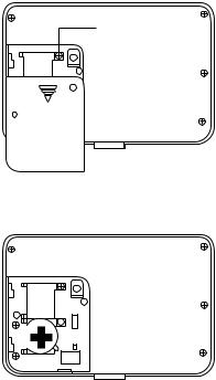
1)Loosen the screw on the back of the SF-4400/4600B that holds the battery compartment cover in place, and remove the cover.
2)Loosen the screw that secures one of the two battery holders in place and remove the battery holder.
Caution:
Be sure to remove only one battery at a time. Otherwise, you will lose all data stored in memory.
Screw
RESET
3)Replace the old battery with a new one, making sure that the positive (+) side of the new battery is facing up (so you can see it).
4)Replace the battery holder and secure it by tightening its screw.
•Be sure careful that you do not over tighten the screw.
5)Repeat steps 2) through 4) for the other two batteries.
•Be sure to replace all two batteries. Never mix old batteries with new ones, and be sure to use CR2032 lithium batteries only.
6)After you replace all two batteries, replace the battery compartment cover and secure it by tightening its screw.
•Be careful that you do not over tighten the screw.
— 5 —

4.DATA TRANSFER
SF-4400/SF-4600B can transfer customers data to other SF-4400/SF4600B with memory protection only when replacing the LCD or the outer case. How to transfer the data.
*Before connecting the cable (SB-60/62), be sure to reset the slave machine to clear all data.
1)Turn off the power switch and connect the two units using the cable (SB-60/62) as shown in the drawing.
SB-60/62 accessory cable
2)Turn on the power switch of each machine.
3)The slave machine must be set the date of Feb. 3rd, 1901 into the memory under the calculator mode.
Operation: 1. |
Press |
ON |
MENU |
|
|
|
|
2. |
Select "CAL" mode or press 6. |
|
|
|
|||
3. |
|
TIME |
|
TIME |
|
TIME |
M+ |
1 |
DATE |
2 |
DATE |
3 |
DATE |
R |
|
M SUN
1901/ 2/ 3
If you don't set the date, the "PASSWORD" isn't transferred to the slave machine.
— 6 —

Setting up for Data Communications
The following procedures describe what you should do to set up for data communications between two SF Units or between an SF Unit and a personal computer. In addition to hardware connections, it details how to set up the communications parameters and how to set up the SF-4400/4600B to receive data. By following these instructions carefully, you can be ensured of successful communications every time.
To connect two SF Units
1.Check to make sure that the power of the two SF Units is switched off.
2.Remove the covers from the connectors on the two SF Units.
3.Connect the two SF Units using the optional SB-60/62 cable. You can also connect them using an SB-60/62 cable.
Important
Be sure to replace the connector covers on the SF Units when you are not performing data communications.
4)Check the hardware parameters.
1.Select "TEL" mode or press 1 under MENU screen.
2.Press FUNC twice to display the second function menu.
FUNC 
 FUNC
FUNC
1* TO SECRET AREA
2 ALL DELETE
3 LABEL EDIT
4 DATA COMM
*If the password isn't registered in the SF unit, display shows X instead of "1".
CAPS
•You can perform the above operation while the initial screen of the Memo Mode, Schedule Keeper, Calendar, or Reminder is displayed also.
3.Press 4 to select DATA COMM.
4
1SEND
2RECEIVE
3SET UP PAR.
CAPS
4.Press 3 to select SET UP.
3
SET UP PAR.
PARITY E O N • N is blinking.
BIT LENGTH 7 8
BPS 4800 9600
CAPS
— 7 —
 Loading...