


48DJ,DK,NP034-074 50DJ,DK,DW,DY,NB,NP034-074 Single Package Heating and Cooling Units
Installation, Start-Up and
Service Instructions
CONTENTS
Page
GENERAL . . . . . . . . . . . . . . . . . . . . . . . . . . . . . . . . . . . 2
SAFETY CONSIDERATIONS . . . . . . . . . . . . . . . . . . . 2
INSTALLATION . . . . . . . . . . . . . . . . . . . . . . . . . . . . . 2-37
Rigging and Unit Placement . . . . . . . . . . . . . . . . . . 2
Roof Curb . . . . . . . . . . . . . . . . . . . . . . . . . . . . . . . . . . . 2
Roof Mount . . . . . . . . . . . . . . . . . . . . . . . . . . . . . . . . . . 2
Slab Mount . . . . . . . . . . . . . . . . . . . . . . . . . . . . . . . . . . 2
Positioning . . . . . . . . . . . . . . . . . . . . . . . . . . . . . . . . . . 3
Field-Fabricated Ductwork . . . . . . . . . . . . . . . . . . . . 6
Condensate Drains . . . . . . . . . . . . . . . . . . . . . . . . . . 10
Install Outdoor Hoods . . . . . . . . . . . . . . . . . . . . . . . 10
·UNIT SIZES 034 AND 044
·UNIT SIZES 054-074
Outdoor-Air Inlet Adjustments . . . . . . . . . . . . . . . 10
·MANUAL OUTDOOR-AIR DAMPER
·ECONOMIZER SETTINGS
Field Wire Routing . . . . . . . . . . . . . . . . . . . . . . . . . . 17
·UNIT SIZES 034 AND 044
·UNIT SIZES 054-074
Field Electrical Connections . . . . . . . . . . . . . . . . . 17
·POWER WIRING
·CONTROL WIRING
Gas Piping (48 Series Units Only) . . . . . . . . . . . . 36
Installing Flue/Inlet Hoods (48 Series Units
Only) . . . . . . . . . . . . . . . . . . . . . . . . . . . . . . . . . . . . . . 36
·UNIT SIZES 034 AND 044
·UNIT SIZES 054-074
PRE-START-UP . . . . . . . . . . . . . . . . . . . . . . . . . . . . 38-41
Unit Preparation . . . . . . . . . . . . . . . . . . . . . . . . . . . . 38
Compressor Mounting . . . . . . . . . . . . . . . . . . . . . . . 38
Evaporator-Fan Shipping Brackets . . . . . . . . . . . 38
·UNIT SIZES 034 AND 044
·UNIT SIZES 054-074
Internal Wiring . . . . . . . . . . . . . . . . . . . . . . . . . . . . . . 38
Refrigerant Service Valves . . . . . . . . . . . . . . . . . . . 38
Crankcase Heaters . . . . . . . . . . . . . . . . . . . . . . . . . . 38
Compressor Oil . . . . . . . . . . . . . . . . . . . . . . . . . . . . . 38
Gas Manifold Pressure (48 Series
Units Only) . . . . . . . . . . . . . . . . . . . . . . . . . . . . . . . . 39
Unit Voltage . . . . . . . . . . . . . . . . . . . . . . . . . . . . . . . . 39
Leak Test and Dehydration . . . . . . . . . . . . . . . . . . 39
Evaporator-Fan Belts, Pulleys, and Sheaves . . 39
Condenser Fans and Motors . . . . . . . . . . . . . . . . . 40
Return-Air Filters . . . . . . . . . . . . . . . . . . . . . . . . . . . 40
Economizer Inlet Screens . . . . . . . . . . . . . . . . . . . 40
Economizer Dampers . . . . . . . . . . . . . . . . . . . . . . . 40
25% Outdoor-Air Damper . . . . . . . . . . . . . . . . . . . . 40
Initial Check . . . . . . . . . . . . . . . . . . . . . . . . . . . . . . . . 41
START-UP . . . . . . . . . . . . . . . . . . . . . . . . . . . . . . . . . 41,42
General . . . . . . . . . . . . . . . . . . . . . . . . . . . . . . . . . . . . . 41
Operating Sequences . . . . . . . . . . . . . . . . . . . . . . . 41
·COOLING, UNITS WITHOUT ECONOMIZER
·HEATING, UNITS WITHOUT ECONOMIZER
Page
·COOLING, UNITS WITH ECONOMIZER
·HEATING, UNITS WITH ECONOMIZER
·VENTILATION AIR CIRCULATION (Continuous Fan)
·AUTOMATIC CHANGEOVER USING AUTOMATIC CHANGEOVER THERMOSTAT
Head Pressure Control . . . . . . . . . . . . . . . . . . . . . . 42
SERVICE . . . . . . . . . . . . . . . . . . . . . . . . . . . . . . . . . . 42-53
Service Access . . . . . . . . . . . . . . . . . . . . . . . . . . . . . 42
·COMPRESSORS
·LIQUID SERVICE VALVES, FILTER DRIERS, AND SIGHT GLASSES
·EVAPORATOR-FAN MOTORS, PULLEYS, AND BELTS
·POWER EXHAUST MOTORS, PULLEYS, AND BELTS
·UNIT CONTROL BOX
·GAS HEAT SECTION (48 Series Units Only)
·MAIN AND PILOT BURNERS (48 Series Units Only)
·FLUE GAS PASSAGEWAYS (48 Series Units Only)
·COMBUSTION AIR BLOWER (48 Series Units Only)
·ECONOMIZER DAMPER MOTOR
·ELECTRIC HEATER CONTROL BOX (50 Series Units Only)
·HEATER BOX (50 Series Units Only)
·25% OUTDOOR-AIR DAMPER
·MODULATING POWER EXHAUST DAMPER MOTOR
·RETURN-AIR FILTERS
·CONDENSER FANS AND FAN MOTORS
·INLET GUIDE VANE MOTOR
Cleaning . . . . . . . . . . . . . . . . . . . . . . . . . . . . . . . . . . . . 45
Lubrication . . . . . . . . . . . . . . . . . . . . . . . . . . . . . . . . . 45
·COMPRESSORS
·FAN SHAFT BEARINGS
·INLET GUIDE VANE BEARINGS (Units With Optional Inlet Guide Vanes)
·FAN MOTOR BEARINGS
·DOOR HINGES
Adjustments . . . . . . . . . . . . . . . . . . . . . . . . . . . . . . . . 46
·EVAPORATOR FAN AND POWER EXHAUST MOTOR PLATE
·MODULATING POWER EXHAUST DIFFERENTIAL PRESSURE SWITCH
·INLET GUIDE VANE DIFFERENTIAL PRESSURE SWITCH (Units With Optional Inlet Guide Vanes and Static Pressure Control)
·BELT INSTALLATION AND TENSIONING
·PULLEY ALIGNMENT
·INSTALLING ALTERNATE MOTOR PULLEY (Evaporator Fan Only)
·CONDENSER FAN ADJUSTMENT
·25% OUTDOOR-AIR DAMPER
·REFRIGERANT CHARGE
·PILOT LIGHT OFF (48 Series Units Only)
Manufacturer reserves the right to discontinue, or change at any time, speci®cations or designs without notice and without incurring obligations.
Book |
1 |
1 |
|
PC 111 |
Catalog No. 564-818 |
Printed in U.S.A. |
Form 48/50D,N-9SI |
Pg 1 |
3-96 |
Replaces: 48DJ,DK-3SI; |
Tab |
1a |
1b |
|
|
|
|
|
|
48/50NB,NP-1SI; 50DJ,DK-9SI |
|
|
|
|
|
|
|
|
|
|
|
|

CONTENTS (cont)
·AUTOMATIC PILOT ADJUSTMENT (48 Series Units Only)
·GAS VALVE ADJUSTMENT (48 Series Units Only)
·MAIN BURNER ADJUSTMENT (48 Series
Units Only)
Main Burner Removal (48 Series Units Only) . . 50
Switch Adjustment . . . . . . . . . . . . . . . . . . . . . . . . . 50
Refrigerant Feed Components . . . . . . . . . . . . . . . 50
Thermostatic Expansion Valve (TXV) . . . . . . . . . 50
Moisture/Liquid Indicator . . . . . . . . . . . . . . . . . . . . 51
Filter Drier . . . . . . . . . . . . . . . . . . . . . . . . . . . . . . . . . . 51
Liquid Line Service Valve . . . . . . . . . . . . . . . . . . . . 51
Compressor Discharge Service Valve . . . . . . . . 51
Compressor Suction Service Valve . . . . . . . . . . . 51
Protective Devices . . . . . . . . . . . . . . . . . . . . . . . . . . 51
·COMPRESSOR PROTECTION
·EVAPORATOR-FAN MOTOR PROTECTION
·CONDENSER-FAN MOTOR PROTECTION
·HIGHAND LOW-PRESSURE SWITCHES
Relief Devices . . . . . . . . . . . . . . . . . . . . . . . . . . . . . . 51
Control Circuit, 115 V . . . . . . . . . . . . . . . . . . . . . . . 52
Control Circuit, 24 v . . . . . . . . . . . . . . . . . . . . . . . . . 52
Electric Heat (50 Series Units Only) . . . . . . . . . . 52
·OVERCURRENT
·OVERTEMPERATURE
Gas Heat (48 Series Units Only) . . . . . . . . . . . . . . 52
·LIMIT SWITCHES
·ROLLOUT SWITCH
TROUBLESHOOTING . . . . . . . . . . . . . . . . . . . . . . 52-69
Economizer . . . . . . . . . . . . . . . . . . . . . . . . . . . . . . . . . 52
·ECONOMIZER MOTOR CHECKOUT
·ECONOMIZER CONTROL BOARD CHECKOUT
Unit Control Board Checkout . . . . . . . . . . . . . . . . 53
·BASIC CHECK
·DETAILED CHECK
START-UP CHECKLIST . . . . . . . . . . . . . . . . . . . . . CL-1
GENERAL
This installation instruction contains base unit installation, start-up, and service instructions only. For complete information on PIC (Product Integrated Controls) and variableair volume (VAV) controls and troubleshooting, refer to appropriate Controls and Troubleshooting literature also enclosed in this literature packet.
SAFETY CONSIDERATIONS
Installation and servicing of air-conditioning equipment can be hazardous due to system pressure and electrical components. Only trained and quali®ed service personnel should install, repair, or service air-conditioning equipment.
Untrained personnel can perform basic maintenance functions of cleaning coils and ®lters and replacing ®lters. All other operations should be performed by trained service personnel. When working on air-conditioning equipment, observe precautions in the literature, tags and labels attached to the unit, and other safety precautions that may apply.
Follow all safety codes, including ANSI (American National Standards Institute) Z223.1. Wear safety glasses and work gloves. Use quenching cloth for unbrazing operations. Have ®re extinguisher available for all brazing operations.
Before performing service or maintenance operations on unit, turn off main power switch to unit. Electrical shock could cause personal injury.
Do not try to light any appliance. Do not touch any electrical switch; do not use any phone in your building. Immediately call your gas supplier from a neighbor's phone. Follow the gas supplier's instructions. If you cannot reach your gas supplier, call the ®re department.
Do not store or use gasoline or other ¯ammable vapors and liquids in the vicinity of this or any other appliance.
Improper installation, adjustment, alteration, service, or maintenance can cause injury or property damage. Refer to this manual. For assistance or additional information, consult a quali®ed installer, service agency, or the gas supplier.
Disconnect gas piping from 48 Series units when leak testing at pressures greater than 0.5 psig. Pressures greater than 0.5 psig will cause gas valve damage resulting in a hazardous condition. If gas valve is subjected to pressure greater than 0.5 psig, it must be replaced. When pressure testing ®eld-supplied gas piping at pressures of 0.5 psig or less, the unit connected to such piping must be isolated by manually closing the gas valve.
INSTALLATION
Rigging and Unit Placement Ð Inspect unit for transportation damage. File claim with transportation agency. Do not drop unit; keep upright. Use spreader bars over unit to prevent sling or cable damage. Sheets of plywood placed along the condenser coils will provide additional protection. All lifting lugs MUST be used when lifting unit. Level by using unit frame as a reference. See Fig. 1 for information. Unit and accessory weights are shown in Tables 1A, 1B, and 2. Weight distribution and center of gravity can be found in Fig. 2.
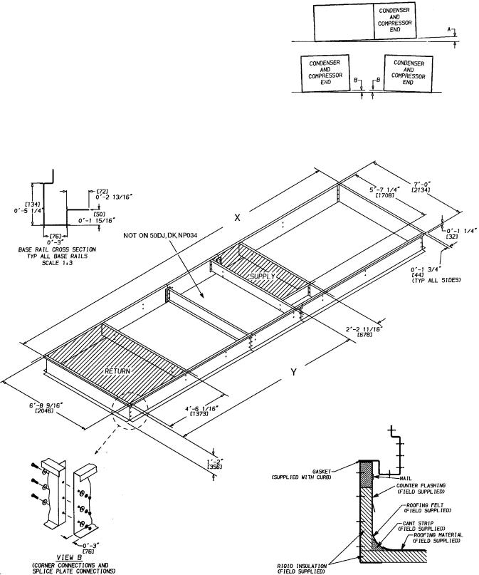
Roof Curb Ð Assemble and install as described in instructions shipped with the accessory. Accessory roof curb and information required to ®eld fabricate a roof curb is shown in Fig. 3A-3C. Install insulation, cant strips, roo®ng and counter ¯ashing as required. For unit condensate drains to function properly, curb must be level or within tolerances shown in Fig. 3A-3C.
Roof Mount Ð Check building codes for weight distribution requirements. Unit weight is shown in Tables 1A and 1B. Unit may be mounted on class A, B, or C roo®ng material.
Slab Mount Ð Provide a level concrete slab that extends beyond unit cabinet at least 6 inches. Make a slab 8 in. thick with 4 in. above grade. Use gravel apron in front of condenser coil air inlet to prevent grass and foliage from obstructing air¯ow.
2
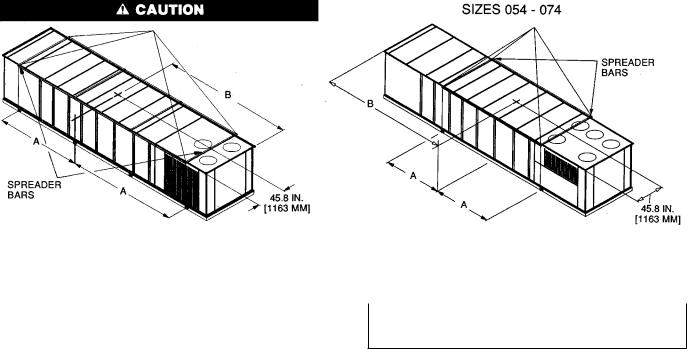
NOTES:
1.Sizes 034,044: Rig with 4 cables and spread with two 95 in. (2413 mm) and 2 8A 1 A8 long spreader bars.
Sizes 054-074: Rig with 4 cables and spread with four 95 in. (2413 mm) and 2 8A 1 B 1 A8 long spreader bars.
2.Center of gravity includes economizer.
1.All panels must be in place when rigging.
2.Unit is not designed for handling by forklift truck.
RIGGING WEIGHTS AND DIMENSIONS
UNIT |
UNIT WEIGHT* |
A |
|
|
B |
|||
Lb |
Kg |
in. |
|
mm |
in. |
|
mm |
|
|
|
|
||||||
48DJD,DKD,NPD034 |
5941 |
2694.8 |
86.0 |
|
2185 |
109.4 |
|
2780 |
48DJE,NPE034 |
6070 |
2753.4 |
|
110.4 |
|
2804 |
||
|
|
|
|
|||||
48DJD,DKD,NPD044 |
6841 |
3103.1 |
92.6 |
|
2353 |
127.6 |
|
3240 |
48DJE,NPE044 |
6970 |
3161.6 |
|
128.6 |
|
3267 |
||
|
|
|
|
|||||
48DJD,DKD,NPD054 |
9230 |
4186.7 |
|
|
|
|
|
|
48DJE,NPE054 |
9350 |
4241.2 |
121.5 |
|
3086 |
126.8 |
|
3221 |
48DJD,DKD,NPD064 |
9530 |
4322.8 |
|
|
||||
|
|
|
|
|
|
|||
48DJE,NPE064 |
9650 |
4377.2 |
|
|
|
|
|
|
48DJD,DKD,NPD074 |
9950 |
4513.3 |
134.7 |
|
3421 |
134.7 |
|
3421 |
48DJE,NPE074 |
10,080 |
4572.3 |
|
|
||||
|
|
|
|
|
|
|||
50DJ,DK,NP034 |
5700 |
2585.5 |
84.8 |
|
2153 |
120.8 |
|
3067 |
50DW,DY,NB034 |
6270 |
2844.1 |
76.4 |
|
1940 |
102.5 |
|
2604 |
50DJ,DK,NP044 |
6350 |
2880.4 |
92.6 |
|
2353 |
126.6 |
|
3216 |
50DW,DY,NB044 |
6920 |
3138.9 |
86.0 |
|
2185 |
108.4 |
|
2753 |
50DJ,DK,NP054 |
8230 |
3733.1 |
120.8 |
|
3066 |
126.8 |
|
3221 |
50DW,DY,NB054 |
8780 |
3982.6 |
109.0 |
|
2769 |
109.0 |
|
2769 |
50DJ,DK,NP064 |
8530 |
3869.2 |
120.9 |
|
3071 |
120.9 |
|
3071 |
50DW,DY,NB064 |
9080 |
4119.7 |
120.8 |
|
3066 |
126.8 |
|
3221 |
50DJ,DK,NP074 |
8960 |
4064.3 |
131.7 |
|
3345 |
137.6 |
|
3495 |
50DW,DY,NB074 |
9500 |
4309.2 |
109.0 |
|
2769 |
109.0 |
|
2769 |
*Includes optional economizer.
Fig. 1 Ð Rigging Label
If roof curb is not used, support unit with steel beams along its entire length and then support steel as required. As a minimum, unit must be supported across its width at each lifting lug location.
Positioning Ð Provide clearance around and above unit for air¯ow, safety, and service access. Do not restrict top (area above condenser fans) in any way. Allow at least 6 ft on all sides for rated performance, code compliance, and service.
Do not install unit in an indoor location. Do not locate air inlets near exhaust vents or other sources of contaminated air.
On units equipped with or power exhaust option, high velocity air is exhausted out the hoods. Unit should be positioned with at least 10 ft clearance between the exhaust hoods and any obstruction. Although unit is weatherproof, guard against water from higher level runoff and overhangs.
3
Table 1A Ð Physical Data; 034, 044 Units
BASE UNIT* |
|
034 |
|
|
044 |
|||
NOMINAL CAPACITY (tons) |
|
30 |
|
|
40 |
|||
OPERATING WEIGHT (lb) |
|
|
|
|
|
|
|
|
Base Unit |
|
|
|
|
|
|
|
|
48 Series, Low Heat |
|
5641 |
|
|
6541 |
|||
48 Series, High Heat |
|
5770 |
|
|
6670 |
|||
50 Series, Horizontal Discharge |
|
5970 |
|
|
6620 |
|||
50 Series, Vertical Discharge |
|
5400 |
|
|
6050 |
|||
With Economizer |
|
|
|
|
|
|
|
|
48 Series, Low Heat |
|
5941 |
|
|
6841 |
|||
48 Series, High Heat |
|
6070 |
|
|
6970 |
|||
50 Series, Horizontal Discharge |
|
6270 |
|
|
6920 |
|||
50 Series, Vertical Discharge |
|
5700 |
|
|
6350 |
|||
COMPRESSORS |
|
|
Semi-Hermetic |
|
|
|||
Quantity...Type |
|
2...06D |
|
|
2...06E |
|||
Capacity Steps (%) |
17, 33, 50, 66, 83, 100 |
|
25, 50, 75, 100 |
|||||
Number of Refrigerant Circuits |
|
2 |
|
|
2 |
|||
REFRIGERANT |
|
|
|
|
|
|
|
|
Operating Charge (lb), Sys 1/Sys 2 |
|
29.0/29.0 |
|
|
40.0/40.0 |
|||
Without Hot Gas Bypass |
|
|
|
|||||
With Hot Gas Bypass |
|
31.0/29.0 |
|
|
42.0/40.0 |
|||
CONDENSER COILS |
|
|
3¤8-in. Tube Diameter |
|
|
|||
Quantity |
|
2 |
|
|
2 |
|||
Rows...Fins/in. |
|
3...15.0 |
|
|
3...15.0 |
|||
Aluminum |
|
|
|
|||||
Copper (Optional) |
|
3...13.7 |
|
|
3...13.7 |
|||
Total Face Area (sq ft) |
|
37.5 |
|
|
50.0 |
|||
EVAPORATOR COILS |
|
|
1¤2-in. Tube Diameter |
|
|
|||
Quantity |
|
1 |
|
|
2 |
|||
Rows...Fins/in. |
|
3...15.0 |
|
|
3...15.0 |
|||
Total Face Area (sq ft) |
|
32.1 |
|
|
45.5 |
|||
Refrigerant Feed Device...No. per Circuit |
|
TXV...1 |
|
|
TXV...2 |
|||
HEATING SECTION (48 Series Units Only) |
Low Heat |
|
High Heat |
|
Low Heat |
|
High Heat |
|
Number of Heat Exchangers |
6 |
|
12 |
|
6 |
|
12 |
|
Input (MBtuh) |
264 |
|
529 |
|
264 |
|
529 |
|
Output (MBtuh) |
211 |
|
423 |
|
211 |
|
423 |
|
Temperature Rise Range (F) |
0-30 |
|
15-45 |
|
0-30 |
|
15-45 |
|
Efficiency (%) |
79 |
|
79 |
|
79 |
|
79 |
|
Burner Ori®ce Diameter |
|
|
|
|
|
|
|
|
Quantity (in. ...drill no.) |
6 (.1285...30) |
|
12 (.1285...30) |
|
6 (.1285...30) |
|
12 (.1285...30) |
|
Pilot Ori®ce Diameter |
|
|
|
|
|
|
|
|
Quantity (in. ...drill no.) |
1 (.076...48) |
|
2 (.076...48) |
|
1 (.076...48) |
|
2 (.076...48) |
|
Firing Stages |
2 |
|
2 |
|
2 |
|
2 |
|
Number of Gas Valves |
1 |
|
2 |
|
1 |
|
2 |
|
CONDENSER FANS |
|
|
Propeller Type |
|
|
|||
Quantity...Diameter (in.) |
|
2...30 |
|
|
3...30 |
|||
Nominal Cfm |
|
18,600 |
|
|
26,000 |
|||
Motor Hp...Rpm |
|
1.0...1140 |
|
|
1.0...1140 |
|||
EVAPORATOR FAN |
|
|
Centrifugal 25 x 25 in. |
|
|
|||
Nominal Cfm |
|
10,500 |
|
|
14,000 |
|||
Maximum Allowable Cfm |
|
15,000 |
|
|
20,000 |
|||
Maximum Allowable Rpm |
|
900 |
|
|
900 |
|||
Shaft Diameter at Pulley (in.) |
|
111¤16 |
|
|
111¤16 |
|||
EVAPORATOR-FAN MOTOR AND DRIVE |
|
|
(Any motor available on any unit) |
|
|
|||
Motor Hp |
7.5 |
|
10.0 |
|
15.0 |
|
20.0 |
|
Motor Frame Size |
213T |
|
215T |
|
254T |
|
256T |
|
Efficiency at Full Load (%) |
|
|
|
|
|
|
|
|
Standard Efficiency |
82.9 |
|
85.6 |
|
84.5 |
|
87.5 |
|
High Efficiency² |
Ð |
|
89.5 |
|
90.0 |
|
91.0 |
|
Fan Pulley Pitch Diameter (in.) |
13.7 |
|
13.7 |
|
13.7 |
|
13.7 |
|
Motor Pulley Pitch Diameter (in.) |
34.4 |
|
4.3 |
|
4.9 |
|
5.5 |
|
Resulting Fan Rpm |
405 |
|
510 |
|
580 |
|
660 |
|
Belts |
Quantity...Model No. |
|
|
|
|
|
|
|
48 Series and 50 Series, Horizontal Discharge |
2...BX60 |
|
2...5VX630 |
|
2...5VX630 |
|
2...5VX630 |
|
50 Series, Vertical Discharge |
2...BX60 |
|
2...5VX630 |
|
2...5VX630 |
|
2...5VX630 |
|
Center Distance Range (in.) |
|
|
|
|
|
|
|
|
48 Series and 50 Series, Horizontal Discharge |
17.74...14.30 |
|
17.74...14.30 |
|
17.63...14.01 |
|
17.63...14.01 |
|
50 Series, Vertical Discharge |
19.86...15.87 |
|
19.86...15.87 |
|
19.04...15.00 |
|
19.04...15.00 |
|
OPTIONAL POWER EXHAUST |
Centrifugal, 15 x 15 in. (Any motor available on any unit) |
|||||||
Quantity...Motor Hp |
2...3.0 |
|
2...5.0 |
|
|
2...7.5 |
||
Motor Frame Size |
56HZ |
|
184T |
|
|
213T |
||
Efficiency at Full Load (%) |
81.0 |
|
84.0 |
|
|
82.9 |
||
Fan Pulley Pitch Diameter (in.) |
6.9 |
|
6.9 |
|
|
6.9 |
||
Motor Pulley Pitch Diameter (in.) |
3.35 |
|
4.12 |
|
|
5.0 |
||
Shaft Diameter at Pulley (in.) |
13¤16 |
|
13¤16 |
|
|
13¤16 |
||
Resulting Fan Rpm |
843 |
|
1040 |
|
|
1264 |
||
Maximum Allowable Rpm |
1300 |
|
1300 |
|
|
1300 |
||
Belts |
Quantity...No. |
2...3VX670 |
|
2...3VX670 |
|
2...3VX710 |
||
FILTERS |
|
|
|
|
|
|
|
|
Standard Efficiency Throwaway (Standard) |
12...20 x 25 x 2 |
|
12...20 x 25 x 2 |
|||||
Quantity...Size (in.) |
4...16 x 20 x 2 |
|
4...16 x 20 x 2 |
|||||
Medium Efficiency (30%) Pleated (Optional) |
12...20 x 25 x 2 |
|
12...20 x 25 x 2 |
|||||
Quantity...Size (in.) |
4...16 x 20 x 2 |
|
4...16 x 20 x 2 |
|||||
High Efficiency (90%) Bag Filters with Pre®lters (Optional) |
6...20 x 24 x 22 |
|
6...20 x 24 x 22 |
|||||
Quantity...Size (in.) |
6...20 x 20 x 22 |
|
6...20 x 20 x 22 |
|||||
TXV Ð Thermostatic Expansion Valve
*Data is for all 48 and 50 Series units of the size listed unless otherwise speci®ed. ²Not available on 575-v units.
4
Table 1B Ð Physical Data; 054-074 Units
BASE UNIT* |
054 |
|
|
064 |
|
|
074 |
||||||
NOMINAL CAPACITY (tons) |
|
50 |
|
|
|
60 |
|
|
|
75 |
|||
OPERATING WEIGHT (lb) |
|
|
|
|
|
|
|
|
|
|
|
|
|
Base Unit |
|
|
|
|
|
|
|
|
|
|
|
|
|
48 Series, Low Heat |
8700 |
|
|
9000 |
|
|
9420 |
||||||
48 Series, High Heat |
8820 |
|
|
9120 |
|
|
9550 |
||||||
50 Series, Horizontal Discharge |
8250 |
|
|
8550 |
|
|
8970 |
||||||
50 Series, Vertical Discharge |
7700 |
|
|
8000 |
|
|
8430 |
||||||
With Economizer |
|
|
|
|
|
|
|
|
|
|
|
|
|
48 Series, Low Heat |
9230 |
|
|
9530 |
|
|
9950 |
||||||
48 Series, High Heat |
9350 |
|
|
9650 |
|
|
10,080 |
||||||
50 Series, Horizontal Discharge |
8780 |
|
|
9080 |
|
|
9500 |
||||||
50 Series, Vertical Discharge |
8230 |
|
|
8530 |
|
|
8960 |
||||||
COMPRESSORS |
|
|
|
|
|
Semi-Hermetic |
|
|
|
|
|||
Quantity...Type |
2...06E |
|
|
2...06E |
|
|
2...06E |
||||||
Capacity Steps (%) |
20, 40, 60, 80, 100 |
|
|
17, 33, 50, 66, 83, 100 |
|
14, 28, 43, 71, 85, 100 |
|||||||
Number of Refrigerant Circuits |
|
2 |
|
|
|
2 |
|
|
|
2 |
|||
REFRIGERANT |
|
|
|
|
|
|
|
|
|
|
|
|
|
Operating Charge (lb), Sys 1/Sys 2 |
|
|
|
|
|
|
|
|
|
|
|
|
|
Without Hot Gas Bypass |
59.0/44.5 |
|
|
61.0/61.0 |
|
|
70.5/64.5 |
||||||
With Hot Gas Bypass |
62.0/44.5 |
|
|
64.0/61.0 |
|
|
73.5/64.5 |
||||||
CONDENSER COILS |
|
|
|
|
|
3¤8-in. Tube Diameter |
|
|
|
|
|||
Quantity |
|
4 |
|
|
|
4 |
|
|
|
4 |
|||
Rows...Fins/in. |
|
|
|
|
|
|
|
|
|
|
|
|
|
Aluminum |
2...17.0, 3...17.0 |
|
|
3...17.0 |
|
|
3...17.0 |
||||||
Copper (Optional) |
2...15.7, 3...15.7 |
|
|
3...15.7 |
|
|
3...15.7 |
||||||
Total Face Area (sq ft) |
72.4 |
|
|
72.4 |
|
|
108.4 |
||||||
EVAPORATOR COILS |
|
|
|
|
|
1¤2-in. Tube Diameter |
|
|
|
|
|||
Quantity |
|
2 |
|
|
|
2 |
|
|
|
2 |
|||
Rows...Fins/in. |
3...17.0 |
|
|
4...17.0 |
|
|
4...17.0 |
||||||
Total Face Area (sq ft) |
61.5 |
|
|
61.5 |
|
|
61.5 |
||||||
Refrigerant Feed Device... |
TXV...2 |
|
|
TXV...2 |
|
|
TXV..2 |
||||||
No. per Circuit |
|
|
|
|
|||||||||
|
|
|
|
|
|
|
|
|
|
|
|
|
|
HEATING SECTION (48 Series Units Only) |
Low Heat |
|
High Heat |
|
Low Heat |
|
High Heat |
|
Low Heat |
|
High Heat |
||
Number of Heat Exchangers |
12 |
|
18 |
|
|
12 |
|
18 |
|
|
12 |
|
18 |
Input (MBtuh) |
540 |
|
810 |
|
|
540 |
|
810 |
|
|
540 |
|
810 |
Output (MBtuh) |
432 |
|
648 |
|
|
432 |
|
648 |
|
|
432 |
|
648 |
Temperature Rise Range (F) |
5-35 |
|
15-45 |
|
5-35 |
|
15-45 |
|
|
5-35 |
|
15-45 |
|
Efficiency (%) |
80 |
|
80 |
|
|
80 |
|
80 |
|
|
80 |
|
80 |
Burner Ori®ce Diameter |
|
|
|
|
|
|
|
|
|
|
|
|
|
Quantity (in. ...drill no.) |
12 (.1285...30) |
|
18 (.1285...30) |
|
12 (.1285...30) |
|
18 (.1285...30) |
|
12 (.1285...30) |
|
18 (.1285...30) |
||
Pilot Ori®ce Diameter |
|
|
|
|
|
|
|
|
|
|
|
|
|
Quantity (in. ...drill no.) |
2 (.076...48) |
|
3 (.076...48) |
|
2 (.076...48) |
|
3 (.076...48) |
|
2 (.076...48) |
|
3 (.076...48) |
||
Firing Stages |
2 |
|
2 |
|
|
2 |
|
2 |
|
|
2 |
|
2 |
Number of Gas Valves |
2 |
|
3 |
|
|
2 |
|
3 |
|
|
2 |
|
3 |
CONDENSER FANS |
|
|
|
|
|
Propeller Type |
|
|
|
|
|||
Quantity...Diameter (in.) |
|
4...30 |
|
|
4...30 |
|
|
5...30 |
|||||
Nominal Cfm |
|
40,000 |
|
|
40,000 |
|
|
50,000 |
|||||
Motor Hp...Rpm |
1.0...1140 |
|
|
1.0...1140 |
|
|
1.0...1140 |
||||||
EVAPORATOR FAN |
|
|
|
|
|
Centrifugal 30 x 27 in. |
|
|
|
|
|||
Nominal Cfm |
|
17,500 |
|
|
21,000 |
|
|
24,500 |
|||||
Maximum Allowable Cfm |
|
25,000 |
|
|
30,000 |
|
|
30,000 |
|||||
Maximum Allowable Rpm |
|
750 |
|
|
750 |
|
|
750 |
|||||
Shaft Diameter at Pulley (in.) |
|
111¤16 |
|
|
111¤16 |
|
|
111¤16 |
|||||
EVAPORATOR-FAN MOTOR AND DRIVE |
|
|
|
|
|
(Any motor available on any unit) |
|
|
|
|
|||
Motor Hp |
15.0 |
|
|
20.0 |
|
25.0 |
|
|
30.0 |
||||
Motor Frame Size |
254T |
|
|
256T |
|
284T |
|
|
286T |
||||
Efficiency at Full Load (%) |
|
|
|
|
|
|
|
|
|
|
|
|
|
Standard Efficiency |
84.5 |
|
|
87.5 |
|
87.1 |
|
|
88.3 |
||||
High Efficiency² |
90.0 |
|
|
91.0 |
|
91.7 |
|
|
92.4 |
||||
Fan Pulley Pitch Diameter (in.) |
13.7 |
|
|
13.7 |
|
13.7 |
|
|
15.5 |
||||
Motor Pulley Pitch Diameter (in.) |
4.5 |
|
|
|
5.1 |
|
5.5 |
|
|
|
5.9 |
||
Resulting Fan Rpm |
555 |
|
|
625 |
|
660 |
|
|
700 |
||||
Belts Quantity...Model No. |
|
|
|
|
|
|
|
|
|
|
|
|
|
48 Series and 50 Series, Horizontal Discharge |
2...5VX1120 |
|
|
2...5VX1150 |
|
2...5VX1150 |
|
|
2...5VX1180 |
||||
50 Series, Vertical Discharge |
2...5VX1230 |
|
|
2...5VX1230 |
|
2...5VX1230 |
|
|
2...5VX1230 |
||||
Center Distance Range (in.) |
|
|
|
|
|
|
|
|
|
|
|
|
|
48 Series and 50 Series, Horizontal Discharge |
48.25...44.00 |
|
|
48.25...44.00 |
|
48.50...44.25 |
|
|
48.50...44.25 |
||||
50 Series, Vertical Discharge |
44.25...39.75 |
|
|
44.25...39.75 |
|
44.00...40.00 |
|
|
44.00...40.00 |
||||
OPTIONAL POWER EXHAUST |
|
|
Centrifugal, 18 x 15 in. (Any motor available on any unit) |
|
|
||||||||
Quantity...Motor Hp |
2...5.0 |
|
|
2...7.5 |
|
|
2...10.0 |
||||||
Motor Frame Size |
184T |
|
|
213T |
|
|
215T |
||||||
Efficiency at Full Load (%) |
84.0 |
|
|
82.9 |
|
|
85.6 |
||||||
Fan Pulley Pitch Diameter (in.) |
10.6 |
|
|
10.6 |
|
|
10.6 |
||||||
Motor Pulley Pitch Diameter (in.) |
|
4.5 |
|
|
|
5.0 |
|
|
|
5.6 |
|||
Shaft Diameter at Pulley (in.) |
17¤16 |
|
|
17¤16 |
|
|
17¤16 |
||||||
Resulting Fan Rpm |
740 |
|
|
820 |
|
|
920 |
||||||
Maximum Allowable Rpm |
925 |
|
|
925 |
|
|
925 |
||||||
FILTERS |
|
|
|
|
|
|
|
|
|
|
|
|
|
Standard Efficiency |
|
|
|
|
|
|
|
|
|
|
|
|
|
Throwaway (Standard) |
15...20 x 25 x 2 |
|
|
15...20 x 25 x 2 |
|
|
15...20 x 25 x 2 |
||||||
Quantity...Size (in.) |
5...16 x 20 x 2 |
|
|
5...16 x 20 x 2 |
|
|
5...16 x 20 x 2 |
||||||
Medium Ef®ciency (30%) Pleated (Optional) |
15...20 x 25 x 2 |
|
|
15...20 x 25 x 2 |
|
|
15...20 x 25 x 2 |
||||||
Quantity...Size (in.) |
5...16 x 20 x 2 |
|
|
5...16 x 20 x 2 |
|
|
5...16 x 20 x 2 |
||||||
High Efficiency (90%) Bag Filters |
|
|
|
|
|
|
|
|
|
|
|
|
|
with Pre®lters (Optional) |
6...20 x 24 x 22 |
|
|
6...20 x 24 x 22 |
|
|
6...20 x 24 x 22 |
||||||
Quantity...Size (in.) |
6...24 x 24 x 22 |
|
|
6...24 x 24 x 22 |
|
|
6...24 x 24 x 22 |
||||||
TXV Ð Thermostatic Expansion Valve
*Data is for all 48 and 50 Series units of the size listed unless otherwise speci®ed. ²Not available on 575-v units.
5
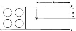
Table 2 Ð Operating Weights of Options and Accessories
OPTION OR ACCESSORY |
|
|
UNIT SIZE |
|
|
|
034 |
044 |
054 |
064 |
074 |
||
|
||||||
Roof Curb |
450 |
480 |
515 |
515 |
515 |
|
48DJ,DK,NP |
||||||
450 |
480 |
560 |
560 |
560 |
||
50DW,DY,NB |
||||||
380 |
465 |
515 |
515 |
515 |
||
50DJ,DK,NP |
||||||
|
|
|
|
|
||
Condenser Section Roof Curb |
Ð |
Ð |
540 |
540 |
625 |
|
Economizer |
300* |
300* |
530* |
530* |
530* |
|
Power Exhaust |
600* |
600* |
710* |
710* |
710* |
|
Barometric Relief |
200 |
200 |
200 |
200 |
200 |
|
High-Efficiency Filters |
20 |
20 |
20 |
20 |
20 |
|
Bag ®lters |
35 |
35 |
40 |
40 |
40 |
|
Hail Guard |
120 |
150 |
145 |
145 |
210 |
|
Copper Condenser Coil Fins |
180 |
235 |
235 |
235 |
420 |
|
Electric Heat² |
150 |
150 |
150 |
150 |
150 |
|
Inlet Guide Vanes |
95 |
95 |
115 |
115 |
115 |
|
|
|
|
|
|
|
*Includes hood.
²50 Series vertical discharge units.
UNIT CENTER OF GRAVITY AND CORNER WEIGHTS
UNIT |
|
|
CORNER WEIGHT (lb) |
|
DIMENSIONS (Ft-in.) |
||
|
1 |
2 |
3 |
4 |
A |
B |
|
|
|
||||||
|
034 |
1754 |
1213 |
1216 |
1758 |
14- 9 |
3- 8 |
|
044 |
2035 |
1382 |
1385 |
2039 |
17- 3 |
3- 8 |
48DJD,DKD,NPD |
054 |
2334 |
2276 |
2281 |
2339 |
19- 7 |
3-10 |
|
064 |
2431 |
2328 |
2334 |
2437 |
19- 7 |
3-10 |
|
074 |
2452 |
2518 |
2523 |
2457 |
21- 0 |
3-10 |
|
034 |
1781 |
1251 |
1253 |
1785 |
14- 8 |
3-10 |
|
044 |
2057 |
1424 |
1428 |
2061 |
17- 2 |
3-10 |
48DJE,NPE |
054 |
2375 |
2295 |
2300 |
2380 |
19- 7 |
3-10 |
|
064 |
2393 |
2373 |
2378 |
2506 |
19- 7 |
3-10 |
|
074 |
2494 |
2541 |
2546 |
2499 |
21- 0 |
3-10 |
|
034 |
1864 |
1268 |
1271 |
1867 |
13- 3 |
3-10 |
|
044 |
2070 |
1387 |
1389 |
2074 |
15-10 |
3-10 |
50DW,DY,NB |
054 |
2381 |
2005 |
2009 |
2385 |
19-10 |
3-10 |
|
064 |
2461 |
2074 |
2078 |
2467 |
19-10 |
3-10 |
|
074 |
2551 |
2194 |
2199 |
2556 |
21- 3 |
3-10 |
|
034 |
1674 |
1173 |
1175 |
1678 |
13- 9 |
3-10 |
|
044 |
1879 |
1292 |
1295 |
1884 |
16- 3 |
3-10 |
50DJ,DK,NP |
054 |
2090 |
2021 |
2025 |
2094 |
18- 2 |
3-10 |
|
064 |
2188 |
2073 |
2077 |
2192 |
18- 2 |
3-10 |
|
074 |
2212 |
2263 |
2269 |
2216 |
21- 3 |
3-10 |
|
|
|
|
|
|
|
|
NOTE: Weights include economizer.
Fig. 2 Ð Weight Distribution and Center of Gravity
Field-Fabricated Ductwork Ð Units are designed for vertical supply/return only. Field-fabricated ductwork should be attached to the roof curb. Supply and return duct dimensions are shown in Fig. 3A-3C.
To attach ductwork to roof curb, insert duct approximately 10 to 11 in. up into roof curb. Connect ductwork to 14-gage roof curb material with sheet metal screws driven from inside of the duct.
Secure all ducts to the building structure, using ¯exible duct connectors between roof curb and ducts as required. Ducts passing through an unconditioned space must be insulated and covered with a vapor barrier. Outlet grilles must not lie directly below unit discharge. The return duct must have a 90-degree elbow before opening into the building space if unit is equipped with power exhaust.
Design supply duct strong enough to handle expected static pressures.
6
UNIT |
|
UNIT |
|
|
X |
|
Y |
|||
MODEL |
|
SIZE |
|
mm |
|
ft-in. |
mm |
ft-in. |
||
48DJ,DK,NP |
034 |
6606 |
21-81¤16 |
4056 |
13- 311¤16 |
|||||
50DW,DY,NB |
034 |
|||||||||
|
|
|
|
|
|
|||||
50DJ,DK,NP |
034 |
6131 |
20-13¤8 |
3311 |
10-103¤8 |
|||||
48DJ,DK,NP |
044 |
7825 |
25-81¤16 |
4893 |
16- 05¤8 |
|||||
50DW,DY,NB |
044 |
|||||||||
|
|
|
|
|
|
|||||
50DJ,DK,NP |
044 |
7344 |
24-11¤8 |
4141 |
13- 71¤16 |
|||||
|
|
|
|
|
|
|
|
|
|
|
|
|
|
|
|
|
|
|
|
|
|
|
|
|
|
|
|
|
|
|
|
|
|
|
|
|
|
|
|
|
|
|
|
NOTES:
1.Roof curb is shipped unassembled.
2.Roof curb: 14 gage (VA03-56) steel.
3. Dimensions in [ ] are millimeters.
NOTE: To prevent the hazard of stagnant water build-up in the drain pan of the indoor-air section, unit can only be pitched as shown.
Fig. 3A Ð Roof Curb; 034, 044 Units
7
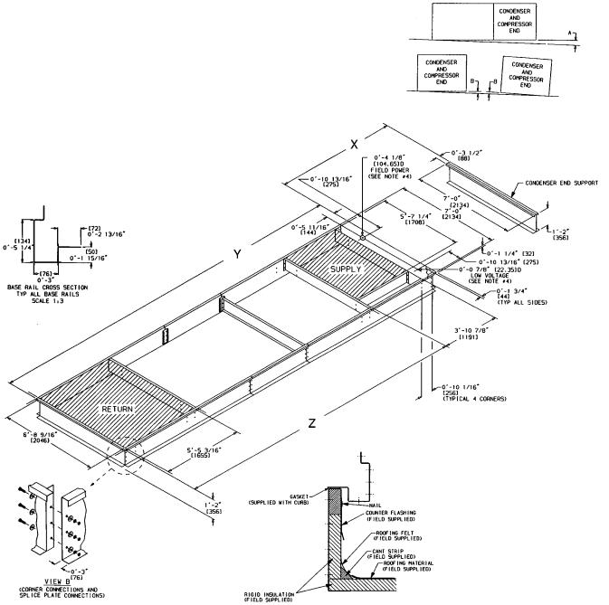
UNIT |
UNIT |
|
|
X |
|
Y |
|
Z |
|||
MODEL |
SIZE |
mm |
ft-in. |
mm |
ft-in. |
mm |
ft-in. |
||||
48DJ,DK,NP |
054,064 |
2474 |
|
8-13¤8 |
|
8476 |
27-911¤16 |
6965 |
22-103¤16 |
||
50DW,DY,NB |
054,064 |
|
|
||||||||
|
|
|
|
|
|
|
|
||||
50DJ,DK,NP |
054,064 |
2458 |
|
8-03¤4 |
|
7444 |
24-51¤16 |
5933 |
19- 59¤16 |
||
48DJ,DK,NP |
074 |
3383 |
|
11-13¤16 |
|
8476 |
27-911¤16 |
6965 |
22-103¤16 |
||
50DW,DY,NB |
074 |
|
|
||||||||
|
|
|
|
|
|
|
|
||||
50DJ,DK,NP |
074 |
3367 |
|
11-09¤16 |
|
7444 |
24-51¤16 |
5933 |
19- 59¤16 |
||
|
|
|
|
|
|
|
|
|
|
|
|
|
|
|
|
|
|
|
|
|
|
|
|
|
|
|
|
|
|
|
|
|
|
|
|
|
|
|
|
|
|
|
|
|
|
|
|
NOTES:
1.Roof curb is shipped unassembled.
2.Roof curb: 14 gage (VA03-56) steel.
3. Dimensions in [ ] are millimeters.
4.Suggested hole location for ®eld wiring through roof curb (holes to be ®eld drilled).
NOTE: To prevent the hazard of stagnant water build-up in the drain pan of the indoor-air section, unit can only be pitched as shown.
Fig. 3B Ð Roof Curb; 054-074 Units
8

UNIT |
DIMENSION X |
|
SIZE |
mm |
Ft-in. |
054,064 |
270 |
0-105¤8 |
074 |
255 |
0-101¤16 |
UNIT LEVELING TOLERANCES
DIMENSIONS* (degrees and inches)
A |
|
|
B |
||
Deg |
|
in. |
Deg |
|
in. |
1.0 |
|
2.0 |
.50 |
|
.75 |
|
|
|
|
|
|
*From edge of unit to horizontal.
water
Fig. 3C Ð Condenser Section Roof Curb (054-074 Units Only)
9
Condensate Drains Ð See Fig. 4A-4D and Fig. 5 for drain locations. The drain assemblies, each consisting of a 10-gage plate with a 11¤4-in. half coupling welded to it, are shipped in the unit fan section. Also included are 16-gage seal plates to cover the drain holes not being used. Open the access door marked FAN SECTION to ®nd the drain assemblies, seal plates, and 4 screws for each mounting taped to the unit basepan.
After the unit has been set in place on the roof:
1.Select the appropriate drain locations. The 034 units have 6 drain holes (3 per side), and the 044-074 units have 8 drain holes (4 per side). Two holes on each side must be selected for condensate drains as shown in Fig. 5, and the remaining holes must be sealed.
2.Remove the drain assemblies and attach them to the bottom of the unit base rails at the preferred drain locations using the screws provided. See Fig. 6.
NOTE: Use a trap at least 4-in. deep.
3.Cover the remaining drain holes with the seal plates and screws provided. See Fig. 7.
4.Apply a bead of RTV or similar sealant around the drain assemblies and seal plates where they attach to the base rail. See Fig. 8.
NOTE: If unit is slab mounted, holes will need to be drilled in the side of the base rail and the holes factory-drilled in the bottom of the base rail will need to be plugged.
Install Outdoor Hoods
UNIT SIZES 034 AND 044
25% Outdoor-Air Hoods (Units Without Economizer
Option)
1.Outdoor-air hoods are shipped bolted to the unit in a shipping position. Remove the 6 screws holding each 25% air hood shipping cover in place.
2.Replace the 6 screws.
3.Remove the holddown screw from each upper corner of each hood.
4.Pivot hoods outward (2 hoods total).
5.Install 17 screws around outside of each hood. (Screws are in the fastener package taped to the basepan inside the fan section.)
6.Apply a bead of RTV or similar sealant to corner of each hood at pivot point to prevent water leaks. See Fig. 9.
Economizer Hoods (Units With Economizer Option) Ð Follow the same procedure described in 25% Outdoor-Air Hoods section above.
UNIT SIZES 054-074
25% Outdoor-Air Hoods Ð The outdoor-air hoods are factory installed on the 054-074 units.
Economizer Hoods (Units With Economizer Option)
1.Remove the 6 screws holding each of the 4 economizer shipping covers in place.
2.Replace the screws.
3.Remove the holddown screw from each upper corner of each economizer hood.
4.Pivot hoods outward. (There is a total of 4 hoods.)
5.Install 18 screws, (5 each side, 6 top, and 2 bottom), around the outside of each hood. (Screws are in the fastener package taped to the basepan inside the fan section.)
6.Apply a bead of RTV or similar sealant to corner of economizer hood at pivot point to prevent water leaks. (See Fig. 9.)
Outdoor-Air Inlet Adjustments
MANUAL OUTDOOR-AIR DAMPER (Units Without Economizer Option) Ð All units except those equipped with a factoryinstalled economizer have a manual outdoor-air damper to provide ventilation air. This damper can be preset to admit up to 25% outdoor air into the return-air compartment. To adjust, loosen the blade limiter screws as shown in Fig. 10 and move the damper to the desired position. Then retighten the blade limiter screws to secure the damper. See Fig. 10. (To make this adjustment, it is necessary to remove the screens covering the hood opening and make adjustments from inside the hood.)
ECONOMIZER SETTINGS
Enthalpy Sensor (See Fig. 11.) Ð This sensor is located behind the ®lters in the end economizer hood (the upper hood on sizes 054-074). See Fig. 12. For maximum bene®t of outdoor air, set enthalpy sensor control to the A setting. At this setting, when the relative humidity is 50%, and the outdoor air is below 74 F, the sensor's relay contacts will be closed. See Fig. 13 and 14.
NOTE: Enthalpy control setting dial is on the economizer motor.
Mixed-Air Thermistor (MAT) Ð This control set point adjustment is on the top of the economizer motor. This motor is located in the return-air section, and is accessed by opening the access panel marked FILTER SECTION. See Fig. 15. Set MAT set point adjustment dial to the desired setting. The factory setting is 55 F ± 5° F; range is 40 to 90 F. The MAT is located on the ®lter rack.
Damper Vent Position Ð The position setting adjustment is located on the cover of the economizer motor. See Fig. 15. Adjust by setting the fan switch at ON position (continuous fan operation), and setting the system selector switch to OFF position. Then turn adjustment screw slowly until the dampers assume the desired vent position. Do not manually operate the damper motor; damage to the motor may result.
Economizer Damper Linkage Adjustment Ð When replacing economizer damper motors, or if the linkage has come loose, it is critical that the linkages be adjusted correctly. They are sensitive, and incorrect adjustment can cause the motor to stall.
NB,NP Unit Minimum Position Set Point Ð Minimum economizer position is set using the keypad and display module. Refer to Control and Troubleshooting literature for more details.
10
UNIT |
SIZE |
WEIGHT |
|
A |
|
B |
|
C |
|
D |
|
E |
|
F |
|
G |
|
H |
|
|
|
J |
|
|
|
|
|
|
|
|
|
|
|
|
|
|
|
|
|
|
|
|
|
|
|
||
|
|
lb |
kg |
mm |
ft-in. |
mm |
ft-in. |
mm |
ft-in. |
mm |
ft-in. |
mm |
ft-in. |
mm |
ft-in. |
mm |
ft-in. |
mm |
ft-in. |
|
mm |
|
ft-in. |
|
|
|
|
|
|
|
|
|
|
|
|
|
|
|
|
|
|
|
|
|
|
|
|
48DJD,DKD,NPD |
|
5641 |
2559 |
4498 |
14-91¤8 |
|
|
|
|
|
|
|
|
|
|
|
|
|
|
|
|
|
|
48DJE,NPE |
034 |
5770 |
2617 |
4474 |
14-81¤8 |
3662 |
12-03¤16 |
7278 |
23-109¤16 |
1709 |
5-75¤16 |
2216 |
7- 31¤4 |
4228 |
13-107¤16 |
2746 |
9-01¤8 |
Ð |
Ð |
|
3626 |
12-10 9¤16 |
|
50DW,DY,NB |
|
5970 |
2708 |
4044 |
13-31¤4 |
|
|
|
|
|
|
|
|
|
|
|
|
|
|
|
|
|
|
48DJD,DKD,NPD |
|
6541 |
2967 |
5255 |
17-27¤8 |
|
|
|
|
|
|
|
|
|
|
|
|
|
|
|
|
|
|
48DJE,NPE |
044 |
6670 |
2708 |
5229 |
17-17¤8 |
4497 |
14-91¤16 |
8496 |
27-101¤2 |
2328 |
7-75¤8 |
2091 |
6-105¤16 |
4706 |
15-5 |
3363 |
11-03¤8 |
3769 |
12-43¤8 |
|
4762 |
15-71¤2 |
|
50DW,DY,NB |
|
6620 |
3003 |
4823 |
15-97¤8 |
|
|
|
|
|
|
|
|
|
|
|
|
|
|
|
|
|
|
UNIT |
SIZE |
|
K |
|
L |
|
|
|
|
|
|
||
|
|
mm |
|
ft-in. |
mm |
ft-in. |
|
|
|
|
|
|
|
48DJD,DKD,NPD |
|
|
|
|
|
|
48DJE,NPE |
034 |
4741 |
|
15-6 |
6797 |
22-35¤8 |
50DW,DY,NB |
|
|
|
|
|
|
|
|
|
|
|
|
|
48DJD,DKD,NPD |
|
|
|
|
|
|
|
|
|
|
|
|
|
48DJE,NPE |
044 |
5576 |
|
8-31¤2 |
8015 |
26-39¤16 |
50DW,DY,NB |
|
|
|
|
|
|
|
|
|
|
|
|
|
LEGEND
CONN Ð Connection
DIM Ð Dimension NOTES:
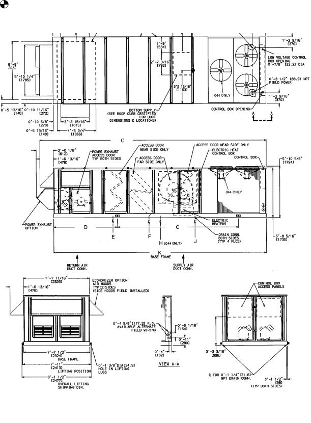
1. Dimensions in [ ] are in millimeters.
2.Center of Gravity includes economizer. Unit weight does not include economizer.
3.Unit clearances:
Top Ð Do not restrict condenser fans Control Box End Ð 6 8-09
Sides Ð 6 8-09
Economizer End Ð 6 8-09 (except power exhaust units 108-09)
For smaller service and operational clearances, contact Carrier Product Engineering Department.
4.Vertical discharge ducts designed to be attached to accessory roof curb. If unit is mounted on dunnage, support the ducts using cross braces as done on the accessory roof curb.
5.When unit is slab mounted, locate the condensate drain as low as possible on vertical face of base rail at the same location as the standard condensate drain (using factory supplied ®tting). Plug factory drilled condensate hole.
Fig. 4A Ð Base Unit Dimensional Drawing; 48DJ,DK,NP/50DW,DY,NB034,044 Units
11
UNIT |
SIZE |
WEIGHT |
|
A |
|
B |
|
C |
D |
|
|
E |
|
F |
|
G |
|
H |
||
|
|
|
|
|
|
|
|
|
|
|
|
|
|
|
|
|
|
|
||
|
|
lb |
kg |
mm |
ft-in. |
mm |
ft-in. |
mm |
ft-in. |
mm |
|
ft-in. |
mm |
ft-in. |
mm |
ft-in. |
mm |
ft-in. |
mm |
ft-in. |
|
|
|
|
|
|
|
|
|
|
|
|
|
|
|
|
|
|
|
|
|
50DJ,DK,NP |
034 |
5400 |
2449 |
4198 |
13-91¤4 |
2916 |
9-613¤16 |
6802 |
22-313¤16 |
1711 |
|
5-73¤8 |
2216 |
7- 31¤4 |
4428 |
9-01¤8 |
3762 |
12-43¤8 |
Ð |
Ð |
044 |
6050 |
2744 |
4948 |
16-213¤16 |
3746 |
12-31¤2 |
8015 |
26-39¤16 |
2247 |
|
7-47¤16 |
2091 |
6-105¤16 |
3363 |
11-03¤8 |
4306 |
14-11¤2 |
3769 |
12-43¤8 |
|
|
|
|||||||||||||||||||
UNIT |
SIZE |
|
J |
|
K |
|
|
|
|
|
|||
|
|
mm |
ft-in. |
mm |
ft-in. |
|
|
|
|
|
|
|
|
50DJ,DK,NP |
034 |
4168 |
13-81¤16 |
6321 |
20-87¤8 |
|
044 |
4999 |
16-413¤16 |
7534 |
24-85¤8 |
||
|
LEGEND
CONN Ð Connection
DIM Ð Dimension NOTES:
1. Dimensions in [ ] are in millimeters.
2.Center of Gravity includes economizer. Unit weight does not include economizer.
3.Unit clearances:
Top Ð Do not restrict condenser fans Control Box End Ð 6 8-09
Sides Ð 6 8-09
Economizer End Ð 6 8-09 (except power exhaust units 108-09)
For smaller service and operational clearances, contact Carrier Product Engineering Department.
4.Vertical discharge ducts designed to be attached to accessory roof curb. If unit is mounted on dunnage, support the ducts using cross braces as done on the accessory roof curb.
5.When unit is slab mounted, locate the condensate drain as low as possible on vertical face of base rail at the same location as the standard condensate drain (using factory supplied ®tting). Plug factory drilled condensate hole.
Fig. 4B Ð Base Unit Dimensional Drawing; 50DJ,DK,NP034,044 Units
12
UNIT |
SIZE |
WEIGHT |
|
A |
|
B |
|
C |
|
D |
|
E |
|
F |
|
|
G |
||
|
|
|
|
|
|
|
|
|
|
|
|
|
|
|
|
|
|
||
|
|
lb |
kg |
mm |
ft-in. |
mm |
ft-in. |
mm |
ft-in. |
mm |
ft-in. |
mm |
ft-in. |
mm |
|
ft-in. |
mm |
|
ft-in. |
|
|
|
|
|
|
|
|
|
|
|
|
|
|
|
|
|
|
|
|
48DJD,DKD,NPD |
|
8700 |
3946 |
5969 |
19-7 |
6717 |
22-07¤16 |
|
|
|
|
2718 |
8-11 |
6541 |
|
21-51¤2 |
|
|
|
48DJE,NPE |
054 |
8820 |
4000 |
1163 |
3-913¤16 |
11,524 |
37-911¤16 |
|
11,140 |
|
36-69¤16 |
||||||||
|
|
|
|
|
|
|
|
|
|
||||||||||
50DW,DY,NB |
|
8250 |
3742 |
6045 |
19-10 |
7676 |
25-23¤16 |
|
|
|
|
2830 |
9-33¤4 |
6427 |
|
21-1 |
|
|
|
48DJD,DKD,NPD |
|
9000 |
4082 |
5969 |
19-7 |
6717 |
22-07¤16 |
|
|
|
|
2718 |
8-11 |
6541 |
|
21-51¤2 |
|
|
|
|
|
|
|
|
|
|
|
|
|
|
|
||||||||
48DJE,NPE |
064 |
9120 |
4137 |
1163 |
3-913¤16 |
11,524 |
37-911¤16 |
11,140 |
|
36-69¤16 |
|||||||||
|
|
|
|
|
|
|
|
|
|
||||||||||
50DW,DY,NB |
|
8550 |
3878 |
6045 |
19-10 |
7676 |
25-23¤16 |
|
|
|
|
2830 |
9-33¤4 |
6427 |
|
21-1 |
|
|
|
48DJD,DKD,NPD |
|
9420 |
4273 |
6401 |
21-0 |
6717 |
22-07¤16 |
|
|
|
|
3543 |
11-71¤2 |
5715 |
|
18-9 |
|
|
|
|
|
|
|
|
|
|
|
|
|
|
|
||||||||
48DJE,NPE |
074 |
9550 |
4332 |
1163 |
3-913¤16 |
12,433 |
40-91¤2 |
12,049 |
|
39-63¤8 |
|||||||||
|
|
|
|
|
|
|
|
|
|
||||||||||
50DW,DY,NB |
|
8970 |
4069 |
6477 |
21-3 |
7676 |
25-23¤16 |
|
|
|
|
3694 |
12-13¤4 |
5563 |
|
18-3 |
|
|
|
LEGEND
CONN Ð Connection
DIM Ð Dimension
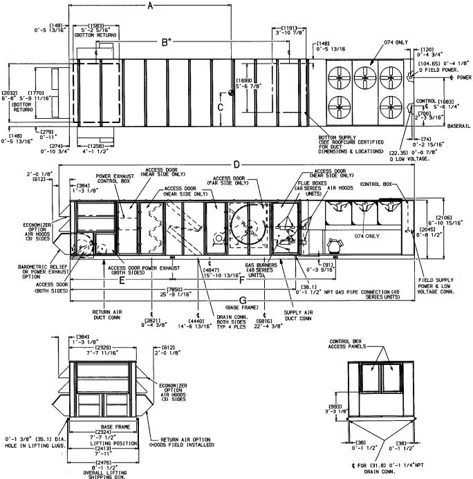
*Dimension shown is for 48 series units. On 50 series units, dimension given is measured from economizer end of unit to drain connection closest to condenser fans.
NOTES:
1. Dimensions in [ ] are in millimeters.
2. Center of Gravity includes economizer. Unit weight does not include economizer.
3.Unit clearances:
Top Ð Do not restrict condenser fans Control Box End Ð 6 8-09
Sides Ð 6 8-09 (except power exhaust units 108-09)
Economizer End Ð 6 8-09 (except power exhaust units 108-09)
For smaller service and operational clearances, contact Carrier Product Engineering Department.
4.Vertical discharge ducts designed to be attached to accessory roof curb. If unit is mounted on dunnage, support the ducts using cross braces as done on the accessory roof curb.
5.When unit is slab mounted, locate the condensate drain as low as possible on vertical face of base rail at the same location as the standard condensate drain (using factory supplied ®tting). Plug factory drilled condensate hole.
Fig. 4C Ð Base Unit Dimensional Drawing; 48DJ,DK,NP/50DW,DY,NB054-074 Units
13

UNIT |
SIZE |
Weight |
|
A |
|
B |
C |
|
|
D |
|
E |
|
|
F |
||||
Lb |
Kg |
mm |
|
ft-in. |
mm |
ft-in. |
mm |
|
ft-in. |
mm |
|
ft-in. |
mm |
|
ft-in. |
mm |
ft-in. |
||
|
|
|
|
|
|
||||||||||||||
|
054 |
7700 |
3493 |
5537 |
|
18-2 |
1163 |
3-913¤16 |
10,476 |
|
34-47¤16 |
2864 |
|
9-43¤4 |
10,092 |
|
33-15¤16 |
5347 |
17-61¤2 |
50DJ,DK,NP |
064 |
8000 |
3629 |
|
|
|
|
||||||||||||
|
|
|
|
|
|
|
|
|
|
|
|
|
|
|
|
||||
|
074 |
8430 |
3824 |
5969 |
|
21-3 |
1163 |
3-913¤16 |
11,385 |
|
37-41¤4 |
3727 |
|
12-23¤4 |
11,001 |
|
36-11¤8 |
4483 |
14-81¤2 |
LEGEND
CONN Ð Connection
DIM Ð Dimension
*Dimension shown is for 48 series units. On 50 series units, dimension given is measured from economizer end of unit to drain connection closest to condenser fans.
NOTES:
1. Dimensions in [ ] are in millimeters.
2.Center of Gravity includes economizer. Unit weight does not include economizer.
3.Unit clearances:
Top Ð Do not restrict condenser fans Control Box End Ð 6 8-09
Sides Ð 6 8-09 (except power exhaust units 108-09)
Economizer End Ð 6 8-09 (except power exhaust units 108-09)
For smaller service and operational clearances, contact Carrier Product Engineering Department.
4.Vertical discharge ducts designed to be attached to accessory roof curb. If unit is mounted on dunnage, support the ducts using cross braces as done on the accessory roof curb.
5.When unit is slab mounted, locate the condensate drain as low as possible on vertical face of base rail at the same location as the standard condensate drain (using factory supplied ®tting). Plug factory drilled condensate hole.
Fig. 4D Ð Base Unit Dimensional Drawing; 50DJ,DK,NP054-074 Units
14
034 UNITS
ROOF MOUNT DRAIN
044-074 UNITS
Fig. 5 Ð Drain Location Selection
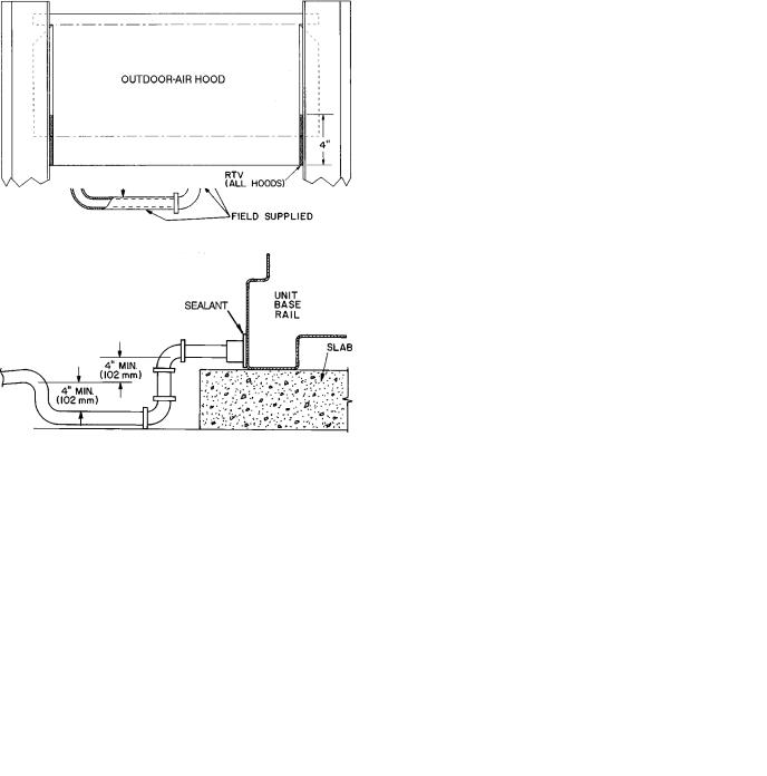
SLAB MOUNT DRAIN
Fig. 8 Ð Condensate Drain Piping Details
Fig. 6 Ð Condensate Drain Location
Fig. 9 Ð Outdoor-Air Hood
Fig. 7 Ð Seal Plate Location
15
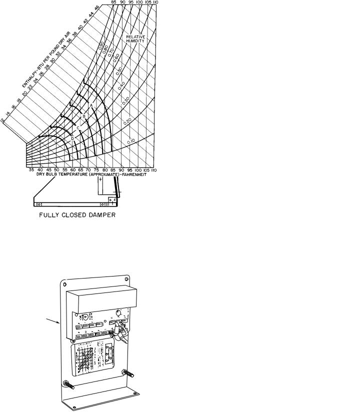
Fig. 12 Ð Enthalpy Sensor Location
Fig. 10 Ð Outdoor-Air Damper Adjustments
(Inside of Hood Shown)
ENTHALPY |
O |
SENSOR |
|
Fig. 11 Ð Enthalpy Sensor
|
CONTROL |
CONTROL |
POINT |
CURVE |
(Approx Deg) |
|
AT 50% RH |
A |
73 |
B |
68 |
C |
63 |
D |
58 |
|
|
Fig. 13 Ð Psychrometric Chart for Enthalpy Control
16
NOTES:
1.Switches shown in high enthalpy state. Terminals 2 and 3 close on enthalpy decrease.
2.When standard economizer is used with accessory differential enthalpy sensor, set enthalpy control to ``D'' setting.
Fig. 14 Ð Wiring Connections for Solid-State Enthalpy Sensor (HH57AC077)
Fig. 15 Ð Mixed-Air Thermistor and Economizer
Position Setting Adjustments
(Top of Economizer Motor)
Field Wire Routing
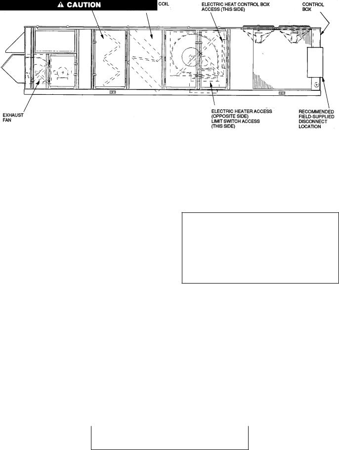
UNIT SIZES 034 AND 044 Ð Field wiring can be brought into the unit through the basepan and roof curb or through the corner post in the side of the unit next to the control box.
A 3-1/2 in. NPT coupling for ®eld power and a 3/4-in. NPT coupling for 24 v control wiring are provided in the basepan. There are two 4-5/8 in. knockouts in the corner post for ®eld power wiring.
If ®eld power wiring is brought through the roof curb, route wiring out through one of the 4-5/8 in. knockouts to the ®eldsupplied disconnect and then back into the unit through the other knockout. See Fig. 16 for recommended disconnect location.
If power wiring is brought through the side of the unit, route wiring from ®eld-supplied disconnect through top 4-5/8 in. knockouts into unit.
If control wiring is to be brought in through the side of the unit, a 7/8-in. diameter hole must be drilled in the corner post next to the control box.
UNIT SIZES 054-074 Ð Field wiring is brought into the unit through the bottom of the control box. Wiring can be brought through the roof curb through ®eld-supplied watertight connections. See Fig. 17.
A 4-5/32 in. hole for ®eld power wiring and a 7/8-in. hole for 24 v control wiring are provided in the bottom of the control box. Field-supplied couplings must be used when routing wiring into the control box.
See Fig. 17 for recommended disconnect location.
Field Electrical Connections
IMPORTANT: The 48/50DK,DY,NB,NP units generate, use, and can radiate radio frequency energy. If units are not installed and used in accordance with these instructions, they may cause radio interference. They have been tested and found to comply with limits of a Class A computing device as de®ned by FCC (Federal Communications Commission) regulations, Subpart J of Part 15, which are designed to provide reasonable protection against such interference when operated in a commercial environment.
Use care when drilling into corner post to avoid damage to condenser coil.
Fig. 16 Ð Disconnect Location, 034 and 044 Units (50 Series Vertical Discharge Unit Shown)
17
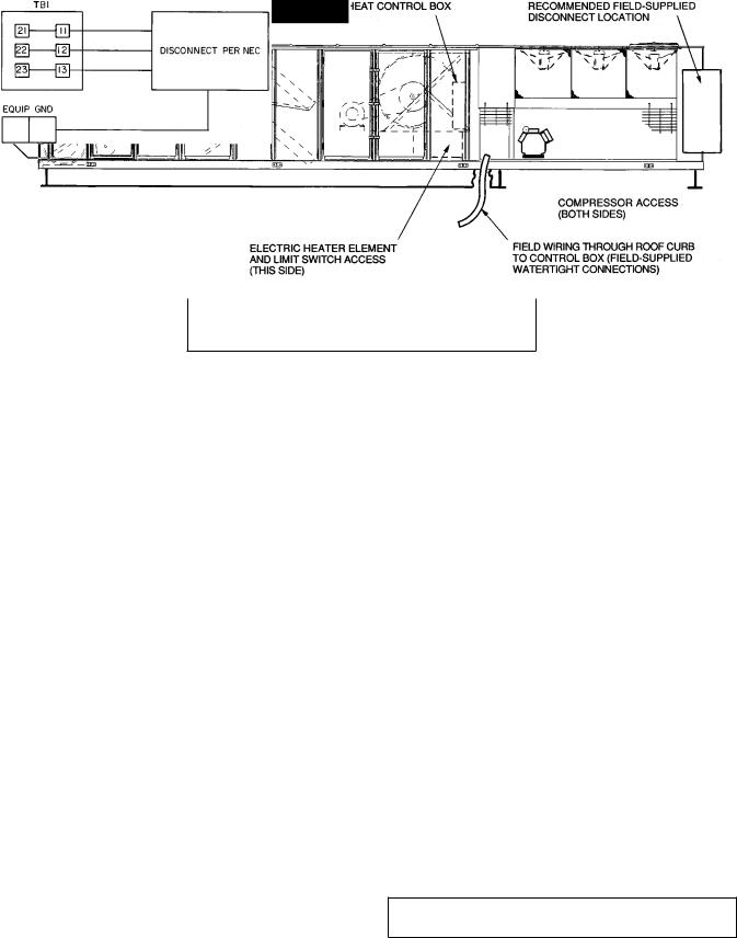
Use care when drilling into corner post to avoid damage to condenser coil.
Fig. 17 Ð Disconnect Location, 054-074 Units (50 Series Horizontal Discharge Shown)
POWER WIRING Ð Units are factory wired for the voltage shown on the unit nameplate. The main terminal block is suitable for use with aluminum or copper wires. Maximum wire size is 3/0 AWG (American Wire Gage).
Use the following formula to determine the percent voltage imbalance.
% Voltage Imbalance
= 100 x |
max voltage deviation from average voltage |
|
When installing units, provide a disconnect per NEC (National Electrical Code) of adequate size (MOCP [Maximum Overcurrent Protection] of unit is on the informative plate). All ®eld wiring must comply with NEC and all local codes. Size wire based on MCA (Minimum Circuit Amps) on the unit informative plate. See Fig. 18 for power wiring connections to the unit power terminal block and equipment ground.
Operating voltage to the compressor must be within the voltage range indicated on the unit nameplate. Voltages between phases must be balanced within 2%, and the current must be balanced within 10%. See Tables 3-7 for unit electrical data.
|
LEGEND |
EQUIP |
Ð Equipment |
GND |
Ð Ground |
NEC |
Ð National Electrical Code |
TB |
Ð Terminal Block |
Fig. 18 Ð Field Power Wiring Connections
average voltage
Example: Supply voltage is 460-3-60.
AB = 452 v
BC = 464 v
AC = 455 v
Average Voltage = |
452 1 464 1 455 |
|||
|
3 |
|||
|
||||
= |
1371 |
|
||
3 |
|
|||
|
|
|||
= 457 |
|
|||
Determine maximum deviation from average voltage:
(AB) 457 ± 452 = 5 v (BC) 464 ± 457 = 7 v (AC) 457 ± 455 = 2 v
Maximum deviation is 7 v.
Determine percent voltage imbalance:
% Voltage Imbalance = 100 x |
7 |
|
457 |
||
= 1.53% |
||
|
This amount of phase imbalance is satisfactory as it is below the maximum allowable 2%.
IMPORTANT: If the supply voltage phase imbalance is more than 2%, contact local utility immediately.
Unit failure as a result of operation on improper line voltage or excessive phase imbalance constitutes abuse and may cause damage to electrical components.
18

Table 3 Ð Electrical Data, 034 Units
208/230-3-60 (V-Ph-Hz)
|
|
|
|
|
|
|
|
|
|
|
|
|
|
|
|
|
|
|
|
BASE UNIT WITH |
||
|
COMPR |
COMPR |
OFM |
|
IFM |
BASE UNIT |
EXHAUST |
|
|
ELECTRIC |
|
|
EXHAUST FAN |
|||||||||
VOLTAGE |
NO. 1 |
NO. 2 |
|
ONLY |
|
FAN |
|
|
|
HEAT* |
|
|
AND/OR |
|||||||||
|
|
|
|
|
|
|
|
|
|
|||||||||||||
RANGE |
|
|
|
|
|
|
|
|
|
|
|
|
|
|
|
|
|
|
|
ELECTRIC HEAT* |
||
|
RLA |
LRA |
RLA |
LRA |
Total |
Hp |
|
FLA |
MCA |
MOCP |
Total |
Total |
|
kW |
|
FLA |
|
MCA |
|
MOCP |
||
|
FLA |
|
Hp |
FLA |
|
|
|
|
||||||||||||||
|
|
|
|
|
|
|
|
|
|
|
|
|
|
|
|
|
|
|
|
|||
|
|
|
|
|
|
|
|
|
|
|
6.0 |
21.2/20.0 |
|
Ð |
|
Ð |
|
|
175.9/172.5 |
|
225/225 |
|
|
|
|
|
|
|
|
|
|
|
|
10.0 |
33.4/30.0 |
|
Ð |
|
Ð |
|
|
188.1/182.5 |
|
225/225 |
|
|
|
|
|
|
|
|
|
|
|
|
15.0 |
48.4/44.0 |
|
Ð |
|
Ð |
|
|
203.1/196.5 |
|
250/225 |
|
|
|
|
|
|
|
|
|
|
|
|
Ð |
Ð |
29/ |
36 |
|
78.9/ 91.0 |
|
154.7/152.5 |
|
200/200 |
||
|
|
|
|
|
|
|
|
|
|
|
Ð |
Ð |
59/ |
72 |
|
157.7/182.0 |
|
227.4/255.0 |
|
250/300 |
||
|
|
|
|
|
|
|
|
|
|
|
Ð |
Ð |
88/108² |
|
236.6/273.0 |
|
326.0/368.8 |
|
350/400 |
|||
|
|
|
|
|
|
7.5 |
|
24.2/ |
154.7/ |
200/ |
6.0 |
21.2/20.0 |
29/ |
36 |
|
78.9/ |
91.0 |
|
175.9/172.5 |
|
225/225 |
|
|
|
|
|
|
|
|
6.0 |
21.2/20.0 |
59/ |
72 |
|
157.7/182.0 |
|
227.4/255.0 |
|
250/300 |
||||||
|
|
|
|
|
|
|
22.0 |
152.5 |
200 |
|
|
|
||||||||||
|
|
|
|
|
|
|
|
6.0 |
21.2/20.0 |
88/108² |
|
236.6/ 273.0 |
|
326.0/368.8 |
|
350/400 |
||||||
|
|
|
|
|
|
|
|
|
|
|
|
|
|
|||||||||
|
|
|
|
|
|
|
|
|
|
|
10.0 |
33.4/30.0 |
29/ |
36 |
|
78.9/ |
91.0 |
|
188.1/182.5 |
|
225/225 |
|
|
|
|
|
|
|
|
|
|
|
|
10.0 |
33.4/30.0 |
59/ |
72 |
|
157.7/182.0 |
|
227.4/255.0 |
|
250/300 |
||
|
|
|
|
|
|
|
|
|
|
|
10.0 |
33.4/30.0 |
88/108² |
|
236.6/273.0 |
|
326.0/368.8 |
|
350/400 |
|||
|
|
|
|
|
|
|
|
|
|
|
15.0 |
48.4/44.0 |
29/ |
36 |
|
78.9/ |
91.0 |
|
203.1/196.5 |
|
250/225 |
|
|
|
|
|
|
|
|
|
|
|
|
15.0 |
48.4/44.0 |
59/ |
72 |
|
157.7/182.0 |
|
227.4/255.0 |
|
250/300 |
||
|
|
|
|
|
|
|
|
|
|
|
15.0 |
48.4/44.0 |
88/108² |
|
236.6/273.0 |
|
326.0/368.8 |
|
350/400 |
|||
|
|
|
|
|
|
|
|
|
|
|
6.0 |
21.2/20.0 |
|
Ð |
|
Ð |
|
|
182.5/178.5 |
|
225/225 |
|
|
|
|
|
|
|
|
|
|
|
|
10.0 |
33.4/30.0 |
|
Ð |
|
Ð |
|
|
194.7/188.5 |
|
225/225 |
|
|
|
|
|
|
|
|
|
|
|
|
15.0 |
48.4/44.0 |
|
Ð |
|
Ð |
|
|
209.7/202.5 |
|
250/250 |
|
|
|
|
|
|
|
|
|
|
|
|
Ð |
Ð |
29/ |
36 |
|
78.9/ 91.0 |
|
161.3/158.5 |
|
200/200 |
||
|
|
|
|
|
|
|
|
|
|
|
Ð |
Ð |
59/ |
72 |
|
157.7/182.0 |
|
235.6/262.5 |
|
250/300 |
||
|
|
|
|
|
|
|
|
|
|
|
Ð |
Ð |
88/108² |
|
236.6/273.0 |
|
334.2/376.3 |
|
350/400 |
|||
|
|
|
|
|
|
10.0 |
|
30.8/ |
161.3/ |
200/ |
6.0 |
21.2/20.0 |
29/ |
36 |
|
78.9/ |
91.0 |
|
182.5/178.5 |
|
225/225 |
|
|
|
|
|
|
|
|
6.0 |
21.2/20.0 |
59/ |
72 |
|
157.7/182.0 |
|
235.6/262.5 |
|
250/300 |
||||||
|
|
|
|
|
|
|
28.0 |
158.5 |
200 |
|
|
|
||||||||||
|
|
|
|
|
|
|
|
6.0 |
21.2/20.0 |
88/108² |
|
236.6/273.0 |
|
334.2/376.3 |
|
350/400 |
||||||
|
|
|
|
|
|
|
|
|
|
|
|
|
|
|||||||||
|
|
|
|
|
|
|
|
|
|
|
10.0 |
33.4/30.0 |
29/ |
36 |
|
78.9/ |
91.0 |
|
194.7/188.5 |
|
225/225 |
|
|
|
|
|
|
|
|
|
|
|
|
10.0 |
33.4/30.0 |
59/ |
72 |
|
157.7/182.0 |
|
235.6/262.5 |
|
250/300 |
||
|
|
|
|
|
|
|
|
|
|
|
10.0 |
33.4/30.0 |
88/108 |
|
236.6/273.0 |
|
334.2/376.3 |
|
350/400 |
|||
|
|
|
|
|
|
|
|
|
|
|
15.0 |
48.4/44.0 |
29/ |
36 |
|
78.9/ |
91.0 |
|
209.7/202.5 |
|
250/250 |
|
|
|
|
|
|
|
|
|
|
|
|
15.0 |
48.4/44.0 |
59/ |
72 |
|
157.7/182.0 |
|
235.6/262.5 |
|
250/300 |
||
187-254 |
53.2 |
266.0 |
53.2 |
266.0 |
10.8 |
|
|
|
|
|
15.0 |
48.4/44.0 |
88/108² |
|
236.6/273.0 |
|
334.2/376.3 |
|
350/400 |
|||
|
|
|
|
|
6.0 |
21.2/20.0 |
|
Ð |
|
Ð |
|
|
197.9/192.5 |
|
250/225 |
|||||||
|
|
|
|
|
|
|
|
|
|
|
|
|
|
|
|
|||||||
|
|
|
|
|
|
|
|
|
|
|
10.0 |
33.4/30.0 |
|
Ð |
|
Ð |
|
|
210.1/202.5 |
|
250/250 |
|
|
|
|
|
|
|
|
|
|
|
|
15.0 |
48.4/44.0 |
|
Ð |
|
Ð |
|
|
225.1/216.5 |
|
250/250 |
|
|
|
|
|
|
|
|
|
|
|
|
Ð |
Ð |
29/ |
36 |
|
78.9/ 91.0 |
|
176.7/172.5 |
|
250/250 |
||
|
|
|
|
|
|
|
|
|
|
|
Ð |
Ð |
59/ |
72 |
|
157.7/182.0 |
|
254.9/280.0 |
|
300/350 |
||
|
|
|
|
|
|
|
|
|
|
|
Ð |
Ð |
88/108² |
|
236.6/273.0 |
|
353.5/393.8 |
|
400/400 |
|||
|
|
|
|
|
|
15.0 |
|
46.2/ |
176.7/ |
225/ |
6.0 |
21.2/20.0 |
29/ |
36 |
|
78.9/ |
91.0 |
|
197.9/192.5 |
|
250/250 |
|
|
|
|
|
|
|
|
6.0 |
21.2/20.0 |
59/ |
72 |
|
157.7/182.0 |
|
254.9/280.0 |
|
300/350 |
||||||
|
|
|
|
|
|
|
42.0 |
172.5 |
225 |
|
|
|
||||||||||
|
|
|
|
|
|
|
|
6.0 |
21.2/20.0 |
88/108² |
|
236.6/273.0 |
|
353.5/393.8 |
|
400/400 |
||||||
|
|
|
|
|
|
|
|
|
|
|
|
|
|
|||||||||
|
|
|
|
|
|
|
|
|
|
|
10.0 |
33.4/30.0 |
29/ |
36 |
|
78.9/ |
91.0 |
|
210.1/202.5 |
|
250/250 |
|
|
|
|
|
|
|
|
|
|
|
|
10.0 |
33.4/30.0 |
59/ |
72 |
|
157.7/182.0 |
|
254.9/280.0 |
|
300/350 |
||
|
|
|
|
|
|
|
|
|
|
|
10.0 |
33.4/30.0 |
88/108 |
|
236.6/273.0 |
|
353.5/393.8 |
|
400/400 |
|||
|
|
|
|
|
|
|
|
|
|
|
15.0 |
48.4/44.0 |
29/ |
36 |
|
78.9/ |
91.0 |
|
225.1/216.5 |
|
250/250 |
|
|
|
|
|
|
|
|
|
|
|
|
15.0 |
48.4/44.0 |
59/ |
72 |
|
157.7/182.0 |
|
254.9/280.0 |
|
300/350 |
||
|
|
|
|
|
|
|
|
|
|
|
15.0 |
48.4/44.0 |
88/108² |
|
236.6/273.0 |
|
353.5/393.8 |
|
400/400 |
|||
|
|
|
|
|
|
|
|
|
|
|
6.0 |
21.2/20.0 |
|
Ð |
|
Ð |
|
|
212.6/204.7 |
|
250/250 |
|
|
|
|
|
|
|
|
|
|
|
|
10.0 |
33.4/30.0 |
|
Ð |
|
Ð |
|
|
224.8/214.7 |
|
250/250 |
|
|
|
|
|
|
|
|
|
|
|
|
15.0 |
48.4/44.0 |
|
Ð |
|
Ð |
|
|
239.9/228.7 |
|
250/250 |
|
|
|
|
|
|
|
|
|
|
|
|
Ð |
Ð |
29/ |
36 |
|
78.9/ 91.0 |
|
191.4/184.7 |
|
300/300 |
||
|
|
|
|
|
|
|
|
|
|
|
Ð |
Ð |
59/ |
72 |
|
157.7/182.0 |
|
271.4/295.0 |
|
350/350 |
||
|
|
|
|
|
|
|
|
|
|
|
Ð |
Ð |
88/108² |
|
236.6/273.0 |
|
370.0/408.8 |
|
450/450 |
|||
|
|
|
|
|
|
20.0 |
|
59.4/ |
191.4/ |
250/ |
6.0 |
21.2/20.0 |
29/ |
36 |
|
78.9/ |
91.0 |
|
212.6/204.7 |
|
300/300 |
|
|
|
|
|
|
|
|
6.0 |
21.2/20.0 |
59/ |
72 |
|
157.7/182.0 |
|
271.4/295.0 |
|
350/350 |
||||||
|
|
|
|
|
|
|
54.0 |
184.7 |
225 |
|
|
|
||||||||||
|
|
|
|
|
|
|
|
6.0 |
21.2/20.0 |
88/108² |
|
236.6/273.0 |
|
370.0/408.8 |
|
450/450 |
||||||
|
|
|
|
|
|
|
|
|
|
|
|
|
|
|||||||||
|
|
|
|
|
|
|
|
|
|
|
10.0 |
33.4/30.0 |
29/ |
36 |
|
78.9/ |
91.0 |
|
224.8/214.7 |
|
300/300 |
|
|
|
|
|
|
|
|
|
|
|
|
10.0 |
33.4/30.0 |
59/ |
72 |
|
157.7/182.0 |
|
271.4/295.0 |
|
350/350 |
||
|
|
|
|
|
|
|
|
|
|
|
10.0 |
33.4/30.0 |
88/108² |
|
236.6/273.0 |
|
370.0/408.8 |
|
450/450 |
|||
|
|
|
|
|
|
|
|
|
|
|
15.0 |
48.4/44.0 |
29/ |
36 |
|
78.9/ |
91.0 |
|
239.9/228.7 |
|
300/300 |
|
|
|
|
|
|
|
|
|
|
|
|
15.0 |
48.4/44.0 |
59/ |
72 |
|
157.7/182.0 |
|
271.4/295.0 |
|
350/350 |
||
|
|
|
|
|
|
|
|
|
|
|
15.0 |
48.4/44.0 |
88/108² |
|
236.6/273.0 |
|
370.0/408.8 |
|
450/450 |
|||
|
|
LEGEND |
CV |
Ð Constant Volume |
|
ETL |
Ð |
ETL Testing Laboratory |
FLA |
Ð |
Full Load Amps |
Hp |
Ð |
Nominal Horsepower |
IFM |
Ð Indoor (Evaporator) Fan Motor |
|
LRA |
Ð |
Locked Rotor Amps |
MCA |
Ð Minimum Circuit Amps (for wire sizing) |
|
MOCP |
Ð Maximum Overcurrent Protection |
|
OFM |
Ð Outdoor (Condenser) Fan Motor |
|
RLA |
Ð |
Rated Load Amps |
*Electric heat available on 50 Series vertical discharge units. ²108 kW available on CV applications only.
NOTES:
1.Electric resistance heaters are rated at 208/240 v, 480 v, or 575 v. To determine heater capacity (kW) at unit operating voltage, multiply 240 v, 480 v, or 575 v capacity by appropriate multiplier below.
MULTIPLICATION FACTORS
HEATER kW |
VOLTAGE |
MULTIPLICATION |
|
DISTRIBUTION |
|||
RATING |
FACTOR |
||
V-3-60 |
|||
|
|
||
|
200 |
0.694 |
|
240 |
208 |
0.751 |
|
230 |
0.918 |
||
|
|||
|
240 |
1.000 |
|
480 |
440 |
0.840 |
|
460 |
0.918 |
||
|
480 |
1.000 |
|
575 |
550 |
0.915 |
|
575 |
1.000 |
||
|
600 |
1.089 |
|
|
|
|
Electric heaters are tested and ETL approved at maximum total external static pressure of 1.9 in. wg.
2.Boldface indicates 48 and 50 Series units. All other data is for 50 Series units only.
19
Table 3 Ð Electrical Data, 034 Units (cont)
460-3-60 (V-Ph-Hz)
|
|
|
|
|
|
|
|
|
|
|
|
|
|
|
|
|
BASE UNIT WITH |
|
|
COMPR |
COMPR |
OFM |
|
IFM |
BASE UNIT |
EXHAUST |
ELECTRIC |
EXHAUST FAN |
|||||||||
VOLTAGE |
NO. 1 |
NO. 2 |
|
|
ONLY |
|
FAN |
HEAT* |
AND/OR |
|||||||||
|
|
|
|
|
|
|||||||||||||
RANGE |
|
|
|
|
|
|
|
|
|
|
|
|
|
|
|
|
ELECTRIC HEAT* |
|
|
RLA |
LRA |
RLA |
LRA |
Total |
Hp |
|
FLA |
MCA |
|
MOCP |
Total |
|
Total |
kW |
FLA |
MCA |
MOCP |
|
FLA |
|
|
Hp |
|
FLA |
||||||||||||
|
|
|
|
|
|
|
|
|
|
|
|
|
|
|
|
|||
|
|
|
|
|
|
|
|
|
|
|
|
6.0 |
|
9.6 |
Ð |
Ð |
90.8 |
110 |
|
|
|
|
|
|
|
|
|
|
|
|
10.0 |
|
15.2 |
Ð |
Ð |
96.4 |
125 |
|
|
|
|
|
|
|
|
|
|
|
|
15.0 |
|
22.0 |
Ð |
Ð |
103.2 |
125 |
|
|
|
|
|
|
|
|
|
|
|
|
Ð |
|
Ð |
36 |
46.3 |
81.2 |
100 |
|
|
|
|
|
|
|
|
|
|
|
|
Ð |
|
Ð |
72 |
93.0 |
130.0 |
150 |
|
|
|
|
|
|
|
|
|
|
|
|
Ð |
|
Ð |
108² |
139.0 |
187.5 |
200 |
|
|
|
|
|
|
7.5 |
|
11.0 |
81.2 |
|
100 |
6.0 |
|
9.6 |
36 |
46.3 |
90.8 |
110 |
|
|
|
|
|
|
|
|
6.0 |
|
9.6 |
72 |
93.0 |
130.0 |
150 |
||||
|
|
|
|
|
|
|
|
|
|
|
|
6.0 |
|
9.6 |
108² |
139.0 |
187.5 |
200 |
|
|
|
|
|
|
|
|
|
|
|
|
10.0 |
|
15.2 |
36 |
46.3 |
96.4 |
125 |
|
|
|
|
|
|
|
|
|
|
|
|
10.0 |
|
15.2 |
72 |
93.0 |
130.0 |
150 |
|
|
|
|
|
|
|
|
|
|
|
|
10.0 |
|
15.2 |
108² |
139.0 |
187.5 |
200 |
|
|
|
|
|
|
|
|
|
|
|
|
15.0 |
|
22.0 |
36 |
46.3 |
103.2 |
125 |
|
|
|
|
|
|
|
|
|
|
|
|
15.0 |
|
22.0 |
72 |
93.0 |
130.0 |
150 |
|
|
|
|
|
|
|
|
|
|
|
|
15.0 |
|
22.0 |
108² |
139.0 |
187.5 |
200 |
|
|
|
|
|
|
|
|
|
|
|
|
6.0 |
|
9.6 |
Ð |
Ð |
93.8 |
110 |
|
|
|
|
|
|
|
|
|
|
|
|
10.0 |
|
15.2 |
Ð |
Ð |
99.4 |
125 |
|
|
|
|
|
|
|
|
|
|
|
|
15.0 |
|
22.0 |
Ð |
Ð |
106.2 |
125 |
|
|
|
|
|
|
|
|
|
|
|
|
Ð |
|
Ð |
36 |
46.3 |
84.2 |
110 |
|
|
|
|
|
|
|
|
|
|
|
|
Ð |
|
Ð |
72 |
93.0 |
133.7 |
150 |
|
|
|
|
|
|
|
|
|
|
|
|
Ð |
|
Ð |
108² |
139.0 |
191.2 |
200 |
|
|
|
|
|
|
10.0 |
|
14.0 |
84.2 |
|
110 |
6.0 |
|
9.6 |
36 |
46.3 |
93.8 |
110 |
|
|
|
|
|
|
|
|
6.0 |
|
9.6 |
72 |
93.0 |
133.7 |
150 |
||||
|
|
|
|
|
|
|
|
|
|
|
|
6.0 |
|
9.6 |
108² |
139.0 |
191.2 |
200 |
|
|
|
|
|
|
|
|
|
|
|
|
10.0 |
|
15.2 |
36 |
46.3 |
99.4 |
125 |
|
|
|
|
|
|
|
|
|
|
|
|
10.0 |
|
15.2 |
72 |
93.0 |
133.7 |
150 |
|
|
|
|
|
|
|
|
|
|
|
|
10.0 |
|
15.2 |
108² |
139.0 |
191.2 |
200 |
|
|
|
|
|
|
|
|
|
|
|
|
15.0 |
|
22.0 |
36 |
46.3 |
106.2 |
125 |
|
|
|
|
|
|
|
|
|
|
|
|
15.0 |
|
22.0 |
72 |
93.0 |
133.7 |
150 |
414-508 |
28.8 |
120.0 |
28.8 |
120.0 |
5.4 |
|
|
|
|
|
|
15.0 |
|
22.0 |
108² |
139.0 |
191.2 |
200 |
|
|
|
|
|
|
6.0 |
|
9.6 |
Ð |
Ð |
100.8 |
125 |
||||||
|
|
|
|
|
|
|
|
|
|
|
|
|
||||||
|
|
|
|
|
|
|
|
|
|
|
|
10.0 |
|
15.2 |
Ð |
Ð |
106.4 |
125 |
|
|
|
|
|
|
|
|
|
|
|
|
15.0 |
|
22.0 |
Ð |
Ð |
113.2 |
125 |
|
|
|
|
|
|
|
|
|
|
|
|
Ð |
|
Ð |
36 |
46.3 |
91.2 |
125 |
|
|
|
|
|
|
|
|
|
|
|
|
Ð |
|
Ð |
72 |
93.0 |
142.5 |
175 |
|
|
|
|
|
|
|
|
|
|
|
|
Ð |
|
Ð |
108² |
139.0 |
200.0 |
200 |
|
|
|
|
|
|
15.0 |
|
21.0 |
91.2 |
|
110 |
6.0 |
|
9.6 |
36 |
46.3 |
100.8 |
125 |
|
|
|
|
|
|
|
|
6.0 |
|
9.6 |
72 |
93.0 |
142.5 |
175 |
||||
|
|
|
|
|
|
|
|
|
|
|
|
6.0 |
|
9.6 |
108² |
139.0 |
200.0 |
200 |
|
|
|
|
|
|
|
|
|
|
|
|
10.0 |
|
15.2 |
36 |
46.3 |
106.4 |
125 |
|
|
|
|
|
|
|
|
|
|
|
|
10.0 |
|
15.2 |
72 |
93.0 |
142.5 |
175 |
|
|
|
|
|
|
|
|
|
|
|
|
10.0 |
|
15.2 |
108² |
139.0 |
200.0 |
200 |
|
|
|
|
|
|
|
|
|
|
|
|
15.0 |
|
22.0 |
36 |
46.3 |
113.2 |
125 |
|
|
|
|
|
|
|
|
|
|
|
|
15.0 |
|
22.0 |
72 |
93.0 |
142.5 |
175 |
|
|
|
|
|
|
|
|
|
|
|
|
15.0 |
|
22.0 |
108² |
139.0 |
200.0 |
200 |
|
|
|
|
|
|
|
|
|
|
|
|
6.0 |
|
9.6 |
Ð |
Ð |
106.8 |
125 |
|
|
|
|
|
|
|
|
|
|
|
|
10.0 |
|
15.2 |
Ð |
Ð |
112.4 |
125 |
|
|
|
|
|
|
|
|
|
|
|
|
15.0 |
|
22.0 |
Ð |
Ð |
119.2 |
125 |
|
|
|
|
|
|
|
|
|
|
|
|
Ð |
|
Ð |
36 |
46.3 |
97.2 |
150 |
|
|
|
|
|
|
|
|
|
|
|
|
Ð |
|
Ð |
72 |
93.0 |
150.0 |
200 |
|
|
|
|
|
|
|
|
|
|
|
|
Ð |
|
Ð |
108² |
139.0 |
207.5 |
225 |
|
|
|
|
|
|
20.0 |
|
27.0 |
97.2 |
|
125 |
6.0 |
|
9.6 |
36 |
46.3 |
106.8 |
150 |
|
|
|
|
|
|
|
|
6.0 |
|
9.6 |
72 |
93.0 |
150.0 |
200 |
||||
|
|
|
|
|
|
|
|
|
|
|
|
6.0 |
|
9.6 |
108² |
139.0 |
207.5 |
225 |
|
|
|
|
|
|
|
|
|
|
|
|
10.0 |
|
15.2 |
36 |
46.3 |
112.4 |
150 |
|
|
|
|
|
|
|
|
|
|
|
|
10.0 |
|
15.2 |
72 |
93.0 |
150.0 |
200 |
|
|
|
|
|
|
|
|
|
|
|
|
10.0 |
|
15.2 |
108² |
139.0 |
207.5 |
225 |
|
|
|
|
|
|
|
|
|
|
|
|
15.0 |
|
22.0 |
36 |
46.3 |
119.2 |
150 |
|
|
|
|
|
|
|
|
|
|
|
|
15.0 |
|
22.0 |
72 |
93.0 |
150.0 |
200 |
|
|
|
|
|
|
|
|
|
|
|
|
15.0 |
|
22.0 |
108² |
139.0 |
207.5 |
225 |
20
Table 3 Ð Electrical Data, 034 Units (cont)
575-3-60 (V-Ph-Hz)
|
|
|
|
|
|
|
|
|
|
|
|
|
|
|
|
|
BASE UNIT WITH |
|
|
COMPR |
COMPR |
OFM |
|
IFM |
BASE UNIT |
EXHAUST |
ELECTRIC |
EXHAUST FAN |
|||||||||
VOLTAGE |
NO. 1 |
NO. 2 |
|
|
ONLY |
|
FAN |
HEAT* |
AND/OR |
|||||||||
|
|
|
|
|
|
|||||||||||||
RANGE |
|
|
|
|
|
|
|
|
|
|
|
|
|
|
|
|
ELECTRIC HEAT* |
|
|
RLA |
LRA |
RLA |
LRA |
Total |
Hp |
|
FLA |
MCA |
|
MOCP |
Total |
|
Total |
kW |
FLA |
MCA |
MOCP |
|
FLA |
|
|
Hp |
|
FLA |
||||||||||||
|
|
|
|
|
|
|
|
|
|
|
|
|
|
|
|
|||
|
|
|
|
|
|
|
|
|
|
|
|
6.0 |
|
7.8 |
Ð |
Ð |
73.6 |
90 |
|
|
|
|
|
|
|
|
|
|
|
|
10.0 |
|
12.2 |
Ð |
Ð |
78.0 |
100 |
|
|
|
|
|
|
|
|
|
|
|
|
15.0 |
|
18.0 |
Ð |
Ð |
83.8 |
100 |
|
|
|
|
|
|
|
|
|
|
|
|
Ð |
|
Ð |
36 |
36.0 |
65.8 |
80 |
|
|
|
|
|
|
|
|
|
|
|
|
Ð |
|
Ð |
72 |
72.0 |
101.3 |
110 |
|
|
|
|
|
|
|
|
|
|
|
|
Ð |
|
Ð |
108² |
108.0 |
146.2 |
150 |
|
|
|
|
|
|
7.5 |
|
9.0 |
65.8 |
|
80 |
6.0 |
|
7.8 |
36 |
36.0 |
73.6 |
90 |
|
|
|
|
|
|
|
|
6.0 |
|
7.8 |
72 |
72.0 |
101.3 |
110 |
||||
|
|
|
|
|
|
|
|
|
|
|
|
6.0 |
|
7.8 |
108² |
108.0 |
146.2 |
150 |
|
|
|
|
|
|
|
|
|
|
|
|
10.0 |
|
12.2 |
36 |
36.0 |
78.0 |
100 |
|
|
|
|
|
|
|
|
|
|
|
|
10.0 |
|
12.2 |
72 |
72.0 |
101.3 |
110 |
|
|
|
|
|
|
|
|
|
|
|
|
10.0 |
|
12.2 |
108² |
108.0 |
146.2 |
150 |
|
|
|
|
|
|
|
|
|
|
|
|
15.0 |
|
18.0 |
36 |
36.0 |
83.8 |
100 |
|
|
|
|
|
|
|
|
|
|
|
|
15.0 |
|
18.0 |
72 |
72.0 |
101.3 |
110 |
|
|
|
|
|
|
|
|
|
|
|
|
15.0 |
|
18.0 |
108² |
108.0 |
146.2 |
150 |
|
|
|
|
|
|
|
|
|
|
|
|
6.0 |
|
7.8 |
Ð |
Ð |
75.6 |
90 |
|
|
|
|
|
|
|
|
|
|
|
|
10.0 |
|
12.2 |
Ð |
Ð |
80.0 |
100 |
|
|
|
|
|
|
|
|
|
|
|
|
15.0 |
|
18.0 |
Ð |
Ð |
85.8 |
100 |
|
|
|
|
|
|
|
|
|
|
|
|
Ð |
|
Ð |
36 |
36.0 |
67.8 |
90 |
|
|
|
|
|
|
|
|
|
|
|
|
Ð |
|
Ð |
72 |
72.0 |
103.7 |
110 |
|
|
|
|
|
|
|
|
|
|
|
|
Ð |
|
Ð |
108² |
108.0 |
148.7 |
150 |
|
|
|
|
|
|
10.0 |
|
11.0 |
67.8 |
|
90 |
6.0 |
|
7.8 |
36 |
36.0 |
75.6 |
90 |
|
|
|
|
|
|
|
|
6.0 |
|
7.8 |
72 |
72.0 |
103.7 |
110 |
||||
|
|
|
|
|
|
|
|
|
|
|
|
6.0 |
|
7.8 |
108² |
108.0 |
148.7 |
150 |
|
|
|
|
|
|
|
|
|
|
|
|
10.0 |
|
12.2 |
36 |
36.0 |
80.0 |
100 |
|
|
|
|
|
|
|
|
|
|
|
|
10.0 |
|
12.2 |
72 |
72.0 |
103.7 |
110 |
|
|
|
|
|
|
|
|
|
|
|
|
10.0 |
|
12.2 |
108² |
108.0 |
148.7 |
150 |
|
|
|
|
|
|
|
|
|
|
|
|
15.0 |
|
18.0 |
36 |
36.0 |
85.8 |
100 |
|
|
|
|
|
|
|
|
|
|
|
|
15.0 |
|
18.0 |
72 |
72.0 |
103.7 |
110 |
518-632 |
23.1 |
96.0 |
23.1 |
96.0 |
4.8 |
|
|
|
|
|
|
15.0 |
|
18.0 |
108² |
108.0 |
148.7 |
150 |
|
|
|
|
|
|
6.0 |
|
7.8 |
Ð |
Ð |
81.6 |
100 |
||||||
|
|
|
|
|
|
|
|
|
|
|
|
|
||||||
|
|
|
|
|
|
|
|
|
|
|
|
10.0 |
|
12.2 |
Ð |
Ð |
86.0 |
100 |
|
|
|
|
|
|
|
|
|
|
|
|
15.0 |
|
18.0 |
Ð |
Ð |
91.8 |
110 |
|
|
|
|
|
|
|
|
|
|
|
|
Ð |
|
Ð |
36 |
36.0 |
73.8 |
100 |
|
|
|
|
|
|
|
|
|
|
|
|
Ð |
|
Ð |
72 |
72.0 |
111.2 |
125 |
|
|
|
|
|
|
|
|
|
|
|
|
Ð |
|
Ð |
108² |
108.0 |
156.2 |
175 |
|
|
|
|
|
|
15.0 |
|
17.0 |
73.8 |
|
90 |
6.0 |
|
7.8 |
36 |
36.0 |
81.6 |
100 |
|
|
|
|
|
|
|
|
6.0 |
|
7.8 |
72 |
72.0 |
111.2 |
125 |
||||
|
|
|
|
|
|
|
|
|
|
|
|
6.0 |
|
7.8 |
108² |
108.0 |
156.2 |
175 |
|
|
|
|
|
|
|
|
|
|
|
|
10.0 |
|
12.2 |
36 |
36.0 |
86.0 |
100 |
|
|
|
|
|
|
|
|
|
|
|
|
10.0 |
|
12.2 |
72 |
72.0 |
111.2 |
125 |
|
|
|
|
|
|
|
|
|
|
|
|
10.0 |
|
12.2 |
108² |
108.0 |
156.2 |
175 |
|
|
|
|
|
|
|
|
|
|
|
|
15.0 |
|
18.0 |
36 |
36.0 |
91.8 |
110 |
|
|
|
|
|
|
|
|
|
|
|
|
15.0 |
|
18.0 |
72 |
72.0 |
111.2 |
125 |
|
|
|
|
|
|
|
|
|
|
|
|
15.0 |
|
18.0 |
108² |
108.0 |
156.2 |
175 |
|
|
|
|
|
|
|
|
|
|
|
|
6.0 |
|
7.8 |
Ð |
Ð |
86.6 |
100 |
|
|
|
|
|
|
|
|
|
|
|
|
10.0 |
|
12.2 |
Ð |
Ð |
91.0 |
110 |
|
|
|
|
|
|
|
|
|
|
|
|
15.0 |
|
18.0 |
Ð |
Ð |
96.8 |
110 |
|
|
|
|
|
|
|
|
|
|
|
|
Ð |
|
Ð |
36 |
36.0 |
78.8 |
110 |
|
|
|
|
|
|
|
|
|
|
|
|
Ð |
|
Ð |
72 |
72.0 |
117.5 |
150 |
|
|
|
|
|
|
|
|
|
|
|
|
Ð |
|
Ð |
108² |
108.0 |
162.5 |
175 |
|
|
|
|
|
|
20.0 |
|
22.0 |
78.8 |
|
100 |
6.0 |
|
7.8 |
36 |
36.0 |
86.6 |
110 |
|
|
|
|
|
|
|
|
6.0 |
|
7.8 |
72 |
72.0 |
117.5 |
150 |
||||
|
|
|
|
|
|
|
|
|
|
|
|
6.0 |
|
7.8 |
108² |
108.0 |
162.5 |
175 |
|
|
|
|
|
|
|
|
|
|
|
|
10.0 |
|
12.2 |
36 |
36.0 |
91.0 |
110 |
|
|
|
|
|
|
|
|
|
|
|
|
10.0 |
|
12.2 |
72 |
72.0 |
117.5 |
150 |
|
|
|
|
|
|
|
|
|
|
|
|
10.0 |
|
12.2 |
108² |
108.0 |
162.5 |
175 |
|
|
|
|
|
|
|
|
|
|
|
|
15.0 |
|
18.0 |
36 |
36.0 |
96.8 |
110 |
|
|
|
|
|
|
|
|
|
|
|
|
15.0 |
|
18.0 |
72 |
72.0 |
117.5 |
150 |
|
|
|
|
|
|
|
|
|
|
|
|
15.0 |
|
18.0 |
108² |
108.0 |
162.5 |
175 |
|
|
LEGEND |
CV |
Ð Constant Volume |
|
ETL |
Ð |
ETL Testing Laboratory |
FLA |
Ð |
Full Load Amps |
Hp |
Ð |
Nominal Horsepower |
IFM |
Ð Indoor (Evaporator) Fan Motor |
|
LRA |
Ð |
Locked Rotor Amps |
MCA |
Ð Minimum Circuit Amps (for wire sizing) |
|
MOCP |
Ð Maximum Overcurrent Protection |
|
OFM |
Ð Outdoor (Condenser) Fan Motor |
|
RLA |
Ð |
Rated Load Amps |
*Electric heat available on 50 Series vertical discharge units. ²108 kW available on CV applications only.
NOTES:
1.Electric resistance heaters are rated at 208/240 v, 480 v, or 575 v. To determine heater capacity (kW) at unit operating voltage, multiply 240 v, 480 v, or 575 v capacity by appropriate multiplier below.
MULTIPLICATION FACTORS
HEATER kW |
VOLTAGE |
MULTIPLICATION |
|
DISTRIBUTION |
|||
RATING |
FACTOR |
||
V-3-60 |
|||
|
|
||
|
200 |
0.694 |
|
240 |
208 |
0.751 |
|
230 |
0.918 |
||
|
|||
|
240 |
1.000 |
|
480 |
440 |
0.840 |
|
460 |
0.918 |
||
|
480 |
1.000 |
|
575 |
550 |
0.915 |
|
575 |
1.000 |
||
|
600 |
1.089 |
Electric heaters are tested and ETL approved at maximum total external static pressure of 1.9 in. wg.
2.Boldface indicates 48 and 50 Series units. All other data is for 50 Series units only.
21
Table 4 Ð Electrical Data, 044 Units
208/230-3-60 (V-Ph-Hz)
|
|
|
|
|
|
|
|
|
|
|
|
|
|
|
|
|
|
|
|
BASE UNIT WITH |
||
|
COMPR |
COMPR |
OFM |
|
IFM |
BASE UNIT |
EXHAUST |
|
|
ELECTRIC |
|
|
EXHAUST FAN |
|||||||||
VOLTAGE |
NO. 1 |
NO. 2 |
|
ONLY |
|
FAN |
|
|
|
HEAT* |
|
|
AND/OR |
|||||||||
|
|
|
|
|
|
|
|
|
|
|||||||||||||
RANGE |
|
|
|
|
|
|
|
|
|
|
|
|
|
|
|
|
|
|
|
ELECTRIC HEAT* |
||
|
RLA |
LRA |
RLA |
LRA |
Total |
Hp |
|
FLA |
MCA |
MOCP |
Total |
Total |
|
kW |
|
FLA |
|
MCA |
|
MOCP |
||
|
FLA |
|
Hp |
FLA |
|
|
|
|
||||||||||||||
|
|
|
|
|
|
|
|
|
|
|
|
|
|
|
|
|
|
|
|
|||
|
|
|
|
|
|
|
|
|
|
|
6.0 |
21.2/20.0 |
|
Ð |
|
Ð |
|
|
217.3/213.9 |
|
250/250 |
|
|
|
|
|
|
|
|
|
|
|
|
10.0 |
33.4/30.0 |
|
Ð |
|
Ð |
|
|
229.5/223.9 |
|
250/250 |
|
|
|
|
|
|
|
|
|
|
|
|
15.0 |
48.4/44.0 |
|
Ð |
|
Ð |
|
|
244.5/237.9 |
|
300/300 |
|
|
|
|
|
|
|
|
|
|
|
|
Ð |
Ð |
29/ |
35 |
|
78.9/ 91.0 |
|
196.1/193.9 |
|
250/250 |
||
|
|
|
|
|
|
|
|
|
|
|
Ð |
Ð |
59/ |
72 |
|
157.7/182.0 |
|
227.4/255.0 |
|
250/300 |
||
|
|
|
|
|
|
|
|
|
|
|
Ð |
Ð |
88/108² |
|
236.6/273.0 |
|
326.0/368.8 |
|
350/400 |
|||
|
|
|
|
|
|
7.5 |
|
24.2/ |
196.1/ |
250/ |
6.0 |
21.2/20.0 |
29/ |
36 |
|
78.9/ |
91.0 |
|
217.3/213.9 |
|
250/250 |
|
|
|
|
|
|
|
|
6.0 |
21.2/20.0 |
59/ |
72 |
|
157.7/182.0 |
|
227.4/255.0 |
|
250/300 |
||||||
|
|
|
|
|
|
|
22.0 |
193.9 |
250 |
|
|
|
||||||||||
|
|
|
|
|
|
|
|
6.0 |
21.2/20.0 |
88/108² |
|
236.6/273.0 |
|
326.0/368.8 |
|
350/400 |
||||||
|
|
|
|
|
|
|
|
|
|
|
|
|
|
|||||||||
|
|
|
|
|
|
|
|
|
|
|
10.0 |
33.4/30.0 |
29/ |
36 |
|
78.9/ |
91.0 |
|
229.5/223.9 |
|
250/250 |
|
|
|
|
|
|
|
|
|
|
|
|
10.0 |
33.4/30.0 |
59/ |
72 |
|
157.7/182.0 |
|
229.5/255.0 |
|
250/300 |
||
|
|
|
|
|
|
|
|
|
|
|
10.0 |
33.4/30.0 |
88/108² |
|
236.6/273.0 |
|
326.0/368.8 |
|
350/400 |
|||
|
|
|
|
|
|
|
|
|
|
|
15.0 |
48.4/44.0 |
29/ |
36 |
|
78.9/ |
91.0 |
|
244.5/237.9 |
|
300/300 |
|
|
|
|
|
|
|
|
|
|
|
|
15.0 |
48.4/44.0 |
59/ |
72 |
|
157.7/182.0 |
|
244.5/255.0 |
|
300/300 |
||
|
|
|
|
|
|
|
|
|
|
|
15.0 |
48.4/44.0 |
88/108² |
|
236.6/273.0 |
|
326.0/368.8 |
|
350/400 |
|||
|
|
|
|
|
|
|
|
|
|
|
6.0 |
21.2/20.0 |
|
Ð |
|
Ð |
|
|
223.9/219.9 |
|
250/250 |
|
|
|
|
|
|
|
|
|
|
|
|
10.0 |
33.4/30.0 |
|
Ð |
|
Ð |
|
|
236.1/229.9 |
|
300/250 |
|
|
|
|
|
|
|
|
|
|
|
|
15.0 |
48.4/44.0 |
|
Ð |
|
Ð |
|
|
251.1/243.9 |
|
300/300 |
|
|
|
|
|
|
|
|
|
|
|
|
Ð |
Ð |
29/ |
36 |
|
78.9/ 91.0 |
|
202.7/199.9 |
|
250/250 |
||
|
|
|
|
|
|
|
|
|
|
|
Ð |
Ð |
59/ |
72 |
|
157.7/182.0 |
|
235.6/262.5 |
|
250/300 |
||
|
|
|
|
|
|
|
|
|
|
|
Ð |
Ð |
88/108² |
|
236.6/273.0 |
|
334.2/376.3 |
|
350/400 |
|||
|
|
|
|
|
|
10.0 |
|
30.8/ |
202.7/ |
250/ |
6.0 |
21.2/20.0 |
29/ |
36 |
|
78.9/ |
91.0 |
|
223.9/219.9 |
|
250/250 |
|
|
|
|
|
|
|
|
6.0 |
21.2/20.0 |
59/ |
72 |
|
157.7/182.0 |
|
235.6/262.5 |
|
250/300 |
||||||
|
|
|
|
|
|
|
28.0 |
199.9 |
250 |
|
|
|
||||||||||
|
|
|
|
|
|
|
|
6.0 |
21.2/20.0 |
88/108² |
|
236.6/273.0 |
|
334.2/376.3 |
|
350/400 |
||||||
|
|
|
|
|
|
|
|
|
|
|
|
|
|
|||||||||
|
|
|
|
|
|
|
|
|
|
|
10.0 |
33.4/30.0 |
29/ |
36 |
|
78.9/ |
91.0 |
|
236.1/229.9 |
|
300/250 |
|
|
|
|
|
|
|
|
|
|
|
|
10.0 |
33.4/30.0 |
59/ |
72 |
|
157.7/182.0 |
|
236.1/262.5 |
|
300/300 |
||
|
|
|
|
|
|
|
|
|
|
|
10.0 |
33.4/30.0 |
88/108² |
|
236.6/273.0 |
|
334.2/376.3 |
|
350/400 |
|||
|
|
|
|
|
|
|
|
|
|
|
15.0 |
48.4/44.0 |
29/ |
36 |
|
78.9/ |
91.0 |
|
251.1/243.9 |
|
300/300 |
|
|
|
|
|
|
|
|
|
|
|
|
15.0 |
48.4/44.0 |
59/ |
72 |
|
157.7/182.0 |
|
251.1/262.5 |
|
300/300 |
||
187-254 |
69.2 |
345.0 |
69.2 |
345.0 |
16.2 |
|
|
|
|
|
15.0 |
48.4/44.0 |
88/108² |
|
236.6/273.0 |
|
334.2/376.3 |
|
350/400 |
|||
|
|
|
|
|
6.0 |
21.2/20.0 |
|
Ð |
|
Ð |
|
|
239.3/233.9 |
|
300/300 |
|||||||
|
|
|
|
|
|
|
|
|
|
|
|
|
|
|
|
|||||||
|
|
|
|
|
|
|
|
|
|
|
10.0 |
33.4/30.0 |
|
Ð |
|
Ð |
|
|
251.5/243.9 |
|
300/300 |
|
|
|
|
|
|
|
|
|
|
|
|
15.0 |
48.4/44.0 |
|
Ð |
|
Ð |
|
|
266.5/257.9 |
|
300/300 |
|
|
|
|
|
|
|
|
|
|
|
|
Ð |
Ð |
29/ |
36 |
|
78.9/ 91.0 |
|
218.1/213.9 |
|
250/250 |
||
|
|
|
|
|
|
|
|
|
|
|
Ð |
Ð |
59/ |
72 |
|
157.7/182.0 |
|
254.9/280.0 |
|
300/350 |
||
|
|
|
|
|
|
|
|
|
|
|
Ð |
Ð |
88/108² |
|
236.6/273.0 |
|
353.5/393.8 |
|
400/400 |
|||
|
|
|
|
|
|
15.0 |
|
46.2/ |
218.1/ |
250/ |
6.0 |
21.2/20.0 |
29/ |
36 |
|
78.9/ |
91.0 |
|
239.3/233.9 |
|
300/300 |
|
|
|
|
|
|
|
|
6.0 |
21.2/20.0 |
59/ |
72 |
|
157.7/182.0 |
|
254.9/280.0 |
|
300/350 |
||||||
|
|
|
|
|
|
|
42.0 |
213.9 |
250 |
|
|
|
||||||||||
|
|
|
|
|
|
|
|
6.0 |
21.2/20.0 |
88/108² |
|
236.6/273.0 |
|
353.5/393.8 |
|
400/400 |
||||||
|
|
|
|
|
|
|
|
|
|
|
|
|
|
|||||||||
|
|
|
|
|
|
|
|
|
|
|
10.0 |
33.4/30.0 |
29/ |
36 |
|
78.9/ |
91.0 |
|
251.5/243.9 |
|
300/300 |
|
|
|
|
|
|
|
|
|
|
|
|
10.0 |
33.4/30.0 |
59/ |
72 |
|
157.7/182.0 |
|
254.9/280.0 |
|
300/350 |
||
|
|
|
|
|
|
|
|
|
|
|
10.0 |
33.4/30.0 |
88/108² |
|
236.6/273.0 |
|
353.5/393.8 |
|
400/400 |
|||
|
|
|
|
|
|
|
|
|
|
|
15.0 |
48.4/44.0 |
29/ |
36 |
|
78.9/ |
91.0 |
|
266.5/257.9 |
|
300/300 |
|
|
|
|
|
|
|
|
|
|
|
|
15.0 |
48.4/44.0 |
59/ |
72 |
|
157.7/182.0 |
|
266.5/280.0 |
|
300/350 |
||
|
|
|
|
|
|
|
|
|
|
|
15.0 |
48.4/44.0 |
88/108² |
|
236.6/273.0 |
|
353.5/393.8 |
|
400/400 |
|||
|
|
|
|
|
|
|
|
|
|
|
6.0 |
21.2/20.0 |
|
Ð |
|
Ð |
|
|
252.5/245.9 |
|
300/300 |
|
|
|
|
|
|
|
|
|
|
|
|
10.0 |
33.4/30.0 |
|
Ð |
|
Ð |
|
|
264.7/255.9 |
|
300/300 |
|
|
|
|
|
|
|
|
|
|
|
|
15.0 |
48.4/44.0 |
|
Ð |
|
Ð |
|
|
279.7/269.9 |
|
300/300 |
|
|
|
|
|
|
|
|
|
|
|
|
Ð |
Ð |
29/ |
36 |
|
78.9/ 91.0 |
|
231.3/225.9 |
|
300/300 |
||
|
|
|
|
|
|
|
|
|
|
|
Ð |
Ð |
59/ |
72 |
|
157.7/182.0 |
|
271.4/295.0 |
|
350/350 |
||
|
|
|
|
|
|
|
|
|
|
|
Ð |
Ð |
88/108² |
|
236.6/273.0 |
|
370.0/408.8 |
|
450/450 |
|||
|
|
|
|
|
|
20.0 |
|
59.4/ |
231.3/ |
300/ |
6.0 |
21.2/20.0 |
29/ |
36 |
|
78.9/ |
91.0 |
|
252.5/245.9 |
|
300/300 |
|
|
|
|
|
|
|
|
6.0 |
21.2/20.0 |
59/ |
72 |
|
157.7/182.0 |
|
271.4/295.0 |
|
350/350 |
||||||
|
|
|
|
|
|
|
54.0 |
225.9 |
250 |
|
|
|
||||||||||
|
|
|
|
|
|
|
|
6.0 |
21.2/20.0 |
88/108² |
|
236.6/273.0 |
|
370.0/408.8 |
|
450/450 |
||||||
|
|
|
|
|
|
|
|
|
|
|
|
|
|
|||||||||
|
|
|
|
|
|
|
|
|
|
|
10.0 |
33.4/30.0 |
29/ |
36 |
|
78.9/ |
91.0 |
|
264.7/255.9 |
|
300/300 |
|
|
|
|
|
|
|
|
|
|
|
|
10.0 |
33.4/30.0 |
59/ |
72 |
|
157.7/182.0 |
|
271.4/295.0 |
|
350/350 |
||
|
|
|
|
|
|
|
|
|
|
|
10.0 |
33.4/30.0 |
88/108² |
|
236.6/273.0 |
|
370.0/408.8 |
|
450/450 |
|||
|
|
|
|
|
|
|
|
|
|
|
15.0 |
48.4/44.0 |
29/ |
36 |
|
78.9/ |
91.0 |
|
279.7/269.9 |
|
300/300 |
|
|
|
|
|
|
|
|
|
|
|
|
15.0 |
48.4/44.0 |
59/ |
72 |
|
157.7/182.0 |
|
279.7/295.0 |
|
350/350 |
||
|
|
|
|
|
|
|
|
|
|
|
15.0 |
48.4/44.0 |
88/108² |
|
236.6/273.0 |
|
370.0/408.8 |
|
450/450 |
|||
22
 Loading...