


Carrier P5 42XPL036H3P, P5 42XPL030C3P, P5 42XPL030H3P, P5 42XPL036C3P, P5 38XPL030H3 User Manual
...-42XPL030C3P/38XPL030C3
-42XPL030H3P/38XPL030H3
-42XPL036C3P/38XPL036C3
-42XPL036H3P/38XPL036H3

Thank you for selecting Carrier!
You can be justifiably proud of your purchase because the same pride in craftsmanship and engineering know-how that goes into Carrier equipment for cooling the Astrodome sports complex in Texas, the United States Capitol’s Halls of Congress and countless other installations worldwide have been built into your unit.
One of the pleasant benefits awaiting you with room air conditioning is that in addition to being cooled, the room air is filtered and dehumidified. This manual is designed to help you be familiar with the many comforts and technological features your unit offers.
Moreover, it contains vital information about maintenance, service and economical operation. Take the next few minutes to discover for yourself how to get the most in personal comfort and economical operation from your new Carrier room air conditioner.
CONTENTS
|
PRECAUTIONS |
2 |
|
|
|
|
|
|
|
|
OWNER’S MANUAL |
|
|
|
|
BEFORE OPERATION |
5 |
|
|
|
UNIT OPERATION |
9 |
|
|
GENERAL OPERATION
AUTOMATIC OPERATION(For Heat Pump Model)
TIMER OPERATION
COMBINATION OF ON, OFF AND DAILY TIMER
SLEEP TIMER
DISCHARGE AIR LOUVER CONTROL
AIR CLEANING OPERATION
CARE AND MAINTENANCE |
17 |
POINTS TO NOTE
CLEANING THE FILTERS AND FRONT PANEL
CLEANING THE MAIN UNIT
AFTER-SEASON CARE
INSTALLATION MANUAL
STANDARD INSTALLATION ACCESSORIES |
20 |
CHOOSING THE UNIT LOCATION |
21 |
INDOOR UNIT |
|
OUTDOOR UNIT |
|
INSTALLATION TIPS |
22 |
INDOOR UNIT INSTALLATION |
23 |
INSTALLING THE WALL HANG BRACKET
MAKING THE WALL PENETRATION FOR THE INTERCONNECTING PIPING INDOOR UNIT WIRING
FORMING THE DRAIN HOSE AND REFRIGERANT PIPING INSTALLING THE INDOOR UNIT BODY TO THE WALL HANG BRACKET
CONNECTING THE PIPING |
28 |
CONNECTING PIPE TO THE INDOOR UNIT |
|
CONNECTING THE INTERCONNECTING PIPE TO THE OUTDOOR UNIT VALVE |
|
AIR PURGE |
29 |
USING THE VACUUM PUMP |
|
GAS LEAK CHECK |
30 |
FINISHING |
30 |
OUTDOOR UNIT WIRING |
31 |
ELECTRICAL CONNECTION |
32 |
CONNECTING THE POWER SUPPLY |
32 |
TEST RUNNING |
33 |
HIGH PRESSURE CONTROL |
33 |
CONFIGURATION |
34 |
PUMP DOWN |
35 |
TROUBLESHOOTING |
36 |
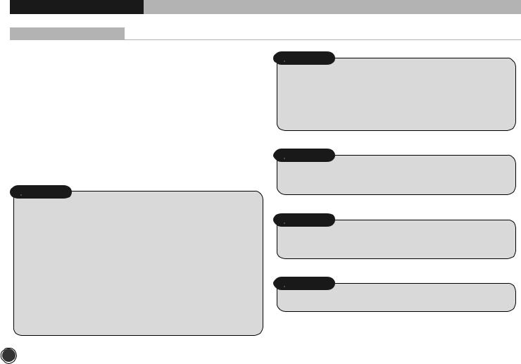
PRECAUTIONS
SAFETY CONSIDERATIONS
Installation and servicing of air conditioning equipment can be hazardous due to system pressure and electric components. Only trained and qualified service personnel should install, repair or service air conditioning equipment.
Untrained personnel can perform basic maintenance functions of cleaning coils and filters, and replacing filters. And untrained personnel don’t include children and persons who with reduced physical sensory or mental capabilities, or lack of experience and knowledge. They should have been given supervision or instruction concerning use of the appliance by person responsible for their safety.
All other operations should be performed by trained service personnel. When working on air conditioning equipment, observe precautions in the literature, tags and labels attached to the unit and other safety precautions that may apply.
Follow all safety codes. Wear glasses and work gloves. Use a quenching cloth for brazing and detaching brazed connections. Have a fire extinguisher available for all brazing operations.
 WARNING
•Do not install by connecting them to other indoor or outdoor units without consulting a Carrier or other competent air conditioning engineers. Mismatching of the units and incompatibility between control devices in the two units could lead to damage of both unit and voiding of the Carrier warranty.
Carrier declines any responsibility, and warranty shall be void if these installation instructions are not observed or if change are made to the electrical connections.Contact your Carrier distributor if you need futher help.
•Before performing service or maintenance operations on the system, turn off the main power switches and breaker of the unit. Electric shock may cause personal injury. “If the supply cord is damaged. It must be replaced with a same size BS approved cord or contact Carrier distributor to arrange for replacement.”
 CAUTION
TO DISCONNECT THE APPLIANCE FROM THE MAIN SUPPLY. This appliance must be connected to the main by means of a circuit breaker or a switch with a contact separation of at least 3 min.
Check that all current national safety code requirements have been followed for the installaltion. In particular ensure that a properly sized and connected ground wire is in place.
 WARNING
Do not switch off the split system by disconnecting the electric power supply. The unit must always be switched off using the remote control.
 WARNING
Check that the impedance of the mains power supply is inconformance with the unit power input indicated in the electric data table, on page 32.
 CAUTION
The mains supply must be connected to the outdoor unit.
2
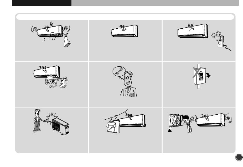
PRECAUTIONS
 WARNING
To avoid the risk of serious electric shock, |
Use the correct voltage. |
Keep heat sources away from the unit, |
never splash the indoor and the outdoor |
Using voltage other than specified will |
high temperature can cause damage. |
unit with water. |
damage the unit. |
|
Do not use flammable sprays near the unit. |
|
Do not use circuit breaker as a means |
|
The unit can be damaged by gasoline, |
|
of turning off the unit. |
|
benzene, thinner, |
Use only fuses of the proper amperage. |
The unit must always be switched off |
|
insecticide and other chemical agents. |
using remote control. |
||
|
Do not put hands or objects into the discharge grille of outdoor unit.
This unit has a fan running at high speed. It is very dangerous to touch the fan.
Do not obstruct the front of the discharge grille of both units.
This will block air flow, reduce the cooling effect and may result in unit malfunction.
In summer, if possible, prevent direct sunlight from entering the room; draw curtains or blinds.
3

PRECAUTIONS
Standard Safety Instructions for Air-Conditioning Units
The air conditioner is not intended for use by young |
Young children should be supervised to ensure that they |
children or special needs persons without supervision |
do not play with the air conditioner. |
by a person that is responsible for their safety. |
|
Wiring connections must be secured tightly and the |
Don’t use a damaged power cord , or loose socket as it |
cable should be routed properly to avoid the risk |
may cause fire or electrical shock |
Do not place the power cord near the heater |
Install the panel and cover the control box securely |
Do not touch the unit with a wet hand , there is a risk of |
Do not place anything on the power cable , there is a |
Electric Shock |
risk of fire and Electric shock |
Two or more people should lift and transport the product |
Always check for gas leakage after installation or repair |
and use proper Safety precautions while lifting the |
of product |
product to avoid personal injury. |
|
4
|
|
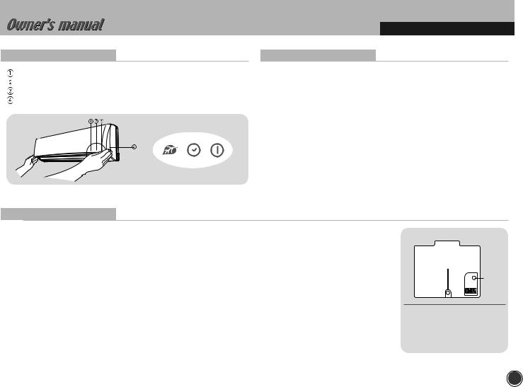
BEFORE OPERATION |
Indoor Unit Display |
Test Operation |
|
Ioniser(Left) light : illuminated during Ioniser activated. |
This operation is used for checking after unit installation. |
|
Timer(Middle) light : illuminated during timer mode. |
• Press the EMER. button continuously during 5~10sec. And then unit will be |
|
Power(Right) light : illuminated during operation. |
operated as test mode. |
|
EMER. button |
• Press the EMER. button once more after checking to activate the remote |
|
|
control. If there is any input signal ( remote control signal or EMER. button |
|
|
press ) during test operation, the TEST mode will change to the input |
|
|
signal mode. |
|
|
• The setting conditions of the test operation are as follows: |
|
|
- Operation mode : COOL |
- Fan speed : HIGH |
|
- Timer mode : Disable |
- Discharge air direction : SWING |
Emergency Operation
When the remote control is lost, damaged or the battery is discharged, the EMER. button can be used to run the unit.
•Press the EMER. button once briefly at the off mode condition shorter than for 5 sec.
-According to the room temperature, the unit operates the Cool mode in cool only model and the Auto mode in Heat pump model.
•If you want to stop the emergency operation, push the EMER. button again or operate the remote control.
•The setting conditions of emergency operation are as follows:
|
|
Model |
Operation |
Preset mode |
Fan speed |
Timer mode |
Discharge air direction |
||
|
|
temperature |
|||||||
|
|
Cooling |
|
|
|
|
|
|
|
|
|
COOL |
24°C |
AUTO |
Disable |
Horizontal |
|||
|
|
only |
|||||||
|
|
|
|
|
|
|
|
|
|
|
|
Heat |
AUTO |
25°C |
AUTO |
Disable |
Preset location according |
||
|
|
Pump |
to ‘Cool’ or ‘Heat’ mode |
||||||
|
|
|
|
|
|
||||
|
|
|
|
|
|
|
|
|
|
EMER. button
•EMER. button :
Can be used when the remote control is lost or inoperative.
5
BEFORE OPERATION
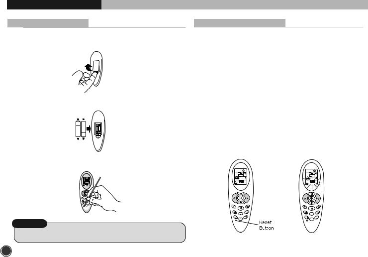
Replacing Batteries
1 Remove the cover of the battery compartment at the back
of the remote control by sliding it out in the direction of the arrow.
2 Remove the used batteries and insert new batteries. The remote control uses two batteries.(1.5V(L)R03x2)
3 Press reset button with a sharp object if the remote control is not operating properly or after replacing the batteries.
NOTE
• Changing batteries should be done after turning off the unit.
Setting Current Time and Reset
4 With the remote control On or OFF, press button  for more than 5 seconds
5 The current hour figure flashes.Press either button  or
or  to set the current hour. Press button
  to move to minutes and set them.
6 For this setting always use either button  or
or  .
.
7Once the current time is set, press button  to confirm it.
6

BEFORE OPERATION
Matching Address between Indoor Unit and Remote Control
When two units are used in the same room, you can match the address of the remote control to that of the unit.
Indoor Unit
Refer the page 35.
Remote control
Refer the page 34.
NOTE
• This function must only be performed by qualified service personnel.
Signal Receiving
Use the remote control where its signals can reach the receiver of the air conditioner. (A distance of 5m is allowed)
• You can hear a beep from the unit which indicates that the signal is received.
5m maximum
 CAUTION
•The air conditioner will not operate if curtained, doors or other materials block the signals from the remote control to the unit.
•If the infrared signal receiver on the unit is exposed to direct sunlight, the air conditioner may not work properly. Draw the curtains to avoid direct sunlight.
•A mounting bracket for the remote control is supplied with the unit. Install the mounting bracket on the wall where the remote signal can be easily received from the remote.
•If the room using the air conditioner has florescent lighting with electronic starter, signals may not be properly received. If you are planning to use such fluorescent lamps, consult your local dealer.
7
BEFORE OPERATION
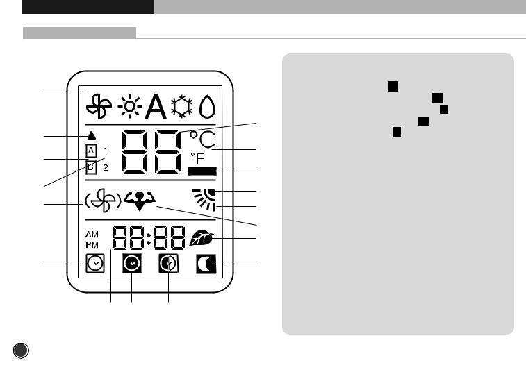
Remote Control Display
|
|
|
1. Operating mode (from left to right): |
||
1 |
|
|
|
• Ventilation (fan only) |
|
|
|
|
• Heating (heat pump models only) |
||
|
|
|
|
||
|
|
|
|
• Automatic (heat pump models only) |
|
|
|
3 |
|
• Cooling and dehumidification |
|
2 |
|
|
|
• Dehumidification only |
|
|
|
2. |
Signal transmission symbol |
||
|
|
5 |
|||
4 |
|
3. |
Temperature selected |
||
|
|
||||
|
|
4. |
Address selector |
||
|
|
7 |
|||
|
|
5. Temperature unit of measurement (°C or °F) |
|||
6 |
|
|
|||
|
8 |
6. |
Unit configuration |
||
|
|
||||
10 |
|
9 |
7. |
Batteries exhausted indicator |
|
|
|
8. |
Vertical louver swing indicator |
||
|
|
11 |
|||
|
|
9. |
Louvre positioning (Flap) |
||
|
|
17 |
10. |
Fan speed |
|
|
|
|
11. |
Turbo mode |
|
12 |
|
13 |
12. |
ON timer selected |
|
|
|
|
13. |
Night timer active |
|
|
|
|
14. |
DAILY timer active (Everyday) |
|
15 |
16 |
14 |
15. |
ON timer, OFF timer and current time |
|
16. |
OFF timer selected |
||||
|
|
|
|||
|
|
|
17. |
Ioniser active |
|
8
UNIT OPERATION
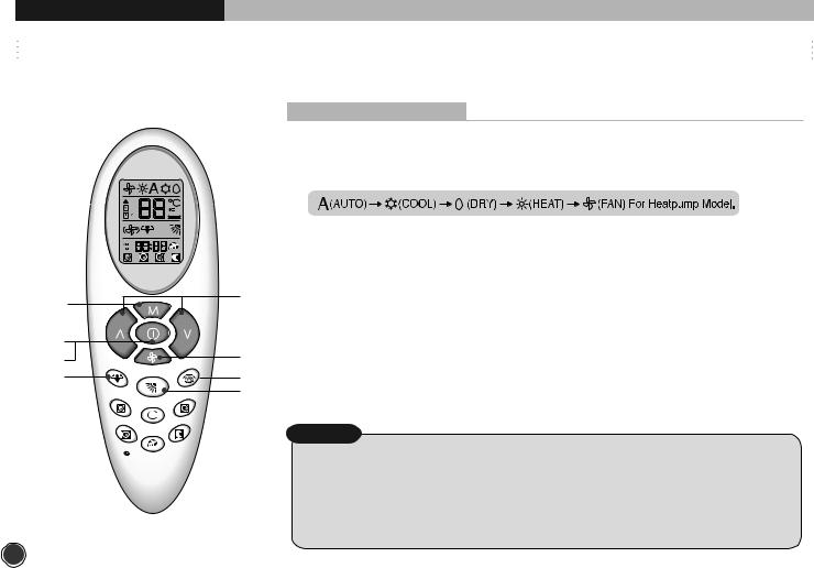
GENERAL OPERATION
PROCEDURE
1 ON/OFF button .........................................................................................................................
Press this button and the COOL (AUTO for Heat Pump Model) operation is indicated.
•A receiving beep is heard.
•The green UNIT ON lamp of the indoor unit display illuminates.
2 MODE button .............................................................................................................................
Press this button to select the desired operation.
3 FAN SPEED button..................................................................................................................
Press this button to select the desired fan speed.
2 |
4 |
4 TEMP.( |
) button ............................................................................................................... |
|
|
Press these buttons to set the desired temperature. |
|
1 |
|
5 HORIZONTAL LOUVER button....................................................................................... |
|
3 |
Press this button to control the desired air flow direction up and down. |
||
7 |
6 VERTICAL LOUVER button .............................................................................................. |
||
8 |
6 |
Press this button to control the desired air flow direction to the left and right side. |
|
|
5 |
7 ON/OFF button ......................................................................................................................... |
|
|
|
Press this button to stop the unit operation. |
|
|
|
•A receiving beep is heard. |
|
|
|
• The UNIT ON lamp is extinguished. |
|
|
|
8 TURBO MODE button ......................................................................................................... |
|
|
|
Press this button to quickly cool down the indoor temperature. |
|
|
|
NOTE |
|
•Dry operation eliminates moisture economically by operating the compressor, indoor and outdoor fan motor intermittently, so that the room temperature
is maintained at the set temperature.
9
UNIT OPERATION
AUTOMATIC OPERATION (For Heat Pump Model)
Automatic operation means that the air conditioner operates automatically by selecting the COOL or HEAT mode and automatically changes the fan speed according to the indoor condition to keep the room temperature comfortable.
2
1
7
8
3
6
5
4
PROCEDURE
1 ON/OFF button .......................................................................................................................................................
Press this button and the unit starts AUTO operation.
2 MODE button...........................................................................................................................................................
If the unit is operating in another mode, press the MODE botton to select Auto.
3 TEMP.(
 ) button .............................................................................................................................................
Set the desired temperature using the remote control buttons. At the start of the AUTO operation,
the temperature is set at 25°c and it is functional with in the total temperature range.
4 HORIZONTAL LOUVER button.....................................................................................................................
Press this button to control the desired air flow direction up and down.
5 VERTICAL LOUVER button ............................................................................................................................
Press this button to control the desired air flow direction to the left and right side.
6 FAN button ...............................................................................................................................................................
Set the desired fan speed. At start up, fan speed is set to AUTO.
7 ON/OFF button .......................................................................................................................................................
Press this button again to stop operation.
8 TURBO MODE button ......................................................................................................................................
Press this button to quickly cool down and heat up indoor temperature.
NOTE
•When the room temperature is between 21°c ~ 29°c.
-If the room temperature is lower 1°c or more than the set temperature : HEAT mode will be operated.
-If the room temperature is higher1°c or more than the set temperature : COOL mode will be operated.
•When the room temperature is lower than 21°c or higher than 29°c, the operation mode is restricted regardless of the set temperature.
-If the room temperature is lower than 21°c then only the heating mode is allowed.
-If the room temperature is higher than 29°c then only the cooling mode is allowed.
•The Auto operation is not suitable for the application to the computer room or some food/wine stock storage.
10
 Loading...