


ZONECC3Z(AC/HP)01
Visit www.carrier.com
Installation and Start-Up Instructions
TABLE OF CONTENTS |
|
|
Page |
SAFETY CONSIDERATIONS................................................... |
1 |
INSTALLATION CONSIDERATIONS.................................... |
1 |
INTRODUCTION ........................................................................ |
1 |
INSTALLATION ...................................................................... |
1-4 |
• Check Equipment And Job Site .............................................. |
1-2 |
• Component Location And Wiring Considerations ..................... |
2 |
• Install Components...................................................................... |
2 |
• Install Zone Dampers............................................................... |
2-4 |
• Install Barometric Bypass Damper ............................................. |
4 |
• Install Leaving Air Temperature (LAT) Sensor......................... |
4 |
• Install Heat Pump Temperature (HPT) Sensor .......................... |
4 |
SYSTEM WIRING ................................................................... |
4-5 |
• Wire Thermostats ........................................................................ |
4 |
• Wire Equipment........................................................................... |
4 |
• Wire Dampers.............................................................................. |
5 |
• Wire Remainder........................................................................... |
5 |
UNDERSTANDING SYSTEM OPERATION ...................... |
6-7 |
SYSTEM SETUP .................................................................... |
7-10 |
NOTE: Read the entire instruction manual before starting the |
|
installation. |
|
SAFETY CONSIDERATIONS
Improper installation, adjustment, alteration, service, maintenance, or use can cause fire, electrical shock, or other conditions which may cause personal injury or property damage. Consult a qualified installer, service agency or your distributor or branch for information or assistance. The qualified installer or agency must use factory-authorized kits or accessories when modifying this product. Refer to the individual instructions packaged with the kits or accessories when installing.
Follow all safety codes and wear safety glasses. Have fire extinguisher available. Read these instructions thoroughly and follow all warnings or cautions attached to the unit. Consult local and state building codes and Sheet Metal and Air Conditioning National Association (SMACNA) for special installation requirements.
Recognize safety information. This is the safety-alert symbol . When you see this symbol on the unit or in instructions and manuals, be alert to the potential for personal injury.
Understand the signal words DANGER, WARNING, and CAUTION. These words are used with the safety-alert symbol. DANGER identifies the most serious hazards which will result in severe personal injury or death. WARNING signifies hazards which could result in personal injury or death. CAUTION is used to identify unsafe practices which would result in minor personal injury or product and property damage. NOTE is used to highlight suggestions which will result in enhanced installation, reliability, or operation.
INSTALLATION CONSIDERATIONS
Before the actual installation of a zoning system can begin, decisions need to be made to determine the number and location of zones. This affects duct and damper selections.
This instruction covers the physical installation and start up of the Carrier 3-Zone system. Use this instruction to guide the actual installation process after all the air side decisions have been made.
1.Install in non-condensing areas with ambients between 32°F and 158°F.
2.A TXV is required on the indoor coil when used with all residential split system equipment.
3.A separate transformer is not needed to power the 3-Zone system. Up to five dampers may be used in each zone by electrically connecting them in parallel.
4.Load calculations must be performed for each zone’s peak demand. Size each zone duct for at least its peak demand plus 25%. Size equipment for the building block load, not the sum of zone peak demands. It is important that the equipment not be oversized.
5.When only two zone operation is needed, any two of the three zone connections may be used. There is no inherent priority dependent on zone number.
UNIT DAMAGE HAZARD
Failure to follow this caution may result in unit damage. TXV on indoor coil is required with all residential split system equipment.
INTRODUCTION
The Carrier 3-Zone system allows the air conditioning and heating equipment to control temperatures in 3 distinct spaces or zones within a building. Each zone has independent temperature settings controlled by a conventional thermostat.
There are two distinct controllers:
•ZONECC3ZAC01 - Single Stage Heat / Single Stage Cool using conventional single stage thermostats.
•ZONECC3ZHP01 - Three Stage Heat / Two Stage Cool compatible for HP and multi-stage application thermostats and equipment.
Each system controller is comprised of a three-zone controller and a duct temperature sensor.
NOTE: Thermostats are purchased separately.
The comfort temperature settings can change automatically through the use of schedules if programmable thermostats are selected. This allows the Carrier 3-Zone to change the temperature settings in zones to reflect occupancy or usage. The Carrier 3-Zone system uses motorized air volume control dampers (also called zone dampers) to regulate the flow of conditioned air into the zones.
INSTALLATION
Step 1—Check Equipment and Job Site
INSPECT EQUIPMENT — File claim with shipping company, prior to installation, if shipment is damaged or incomplete.
Manufacturer reserves the right to discontinue, or change at any time, specifications or designs without notice and without incurring obligations.
Book |
1 |
1 |
4 |
4 |
PC 101 |
Catalog No. 809-50009 |
Printed in U.S.A. |
Form ZONEKIT-15SI |
Pg 1 |
11-04 |
Replaces: NEW |
Tab |
3a |
5a |
2a |
5a |
|
|
|
|
|
|
|

Step 2—Component Location and Wiring
Considerations
ELECTRICAL SHOCK HAZARD
Failure to follow this warning could result in personal injury or death.
Turn off unit before routing routing control wiring or any service operation. Remember, there may be more than one power supply to unit.
All wiring must comply with national, local, and state codes.
LOCATING CARRIER 3-ZONE SYSTEM — All wiring is run back to the Carrier 3-Zone System. Select a location near the furnace or fan coil where wiring from each thermostat, each damper actuator, and the equipment itself can come together easily.
The Carrier 3-Zone System is approved for indoor use only and should never be installed with any of its components exposed to the elements. It may be installed in any area where the temperature remains between 32° and 158°F, and there is no condensation. The cover must be installed to prevent damage from other sources. Do not locate where it will be accessible to children. It may be mounted in either vertical or horizontal position. Remember that wiring access is likely the most important consideration.
EQUIPMENT DAMAGE HAZARD
Failure to follow this caution may result in equipment damage.
To prevent possible damage to Carrier 3-Zone System, do not mount control on plenum, duct work, or flush against furnace.
LOCATING THERMOSTATS — For proper operation, each thermostat must accurately measure the temperature within its zone.
For accurate temperature measurement, the following guidelines should be followed:
Thermostat should be mounted:
•Approximately 5 ft. (1.5m) from floor.
•Close to the center of its zone, preferably on an inside wall.
•On a section of wall without pipes or duct work. Thermostat should NOT be mounted:
•Close to a window, on an outside wall, or next to a door leading to the outside.
•Where it will be exposed to direct light and heat from a lamp, sun, fireplace, or other temperature radiating object which may cause a false reading.
•Close to or in direct airflow from supply registers and return-air grilles.
•In areas with poor air circulation, such as behind a door or in an alcove.
WIRING CONSIDERATIONS — All wiring in the Carrier ThreeZone system may be unshielded. Ordinary thermostat wire is ideal. Use 22 gage or larger for normal wiring. Lengths over 100 ft. should use 20 gage or larger wire.
Each damper actuator requires 3 conductors. The connection to thermostats and equipment (furnace or fan coil) could require as many as 8 conductors for a multi-stage installation. The leaving air temperature (LAT) and heat pump temperature (HPT)—(used with heat pumps only) sensors require 2 conductors each.
Cables with excess conductors are acceptable. Cut off or fold back and tape any unneeded conductors.
Plan the routing of wiring early to avoid possible problems later on.
Remember all wires converge at the Carrier 3-Zone system, so its location is important.
Step 3—Install Components
INSTALL CARRIER 3-ZONE SYSTEM
The Carrier 3-Zone System is designed so that wires can enter it from behind, above, or below. Plan wire routing before mounting.
1.Open door to access eight mounting screw slots
2.Mount to wall using four screws and wall anchors provided.
3.Level and tighten screws.
INSTALL THERMOSTATS
1.Follow manufacturer’s supplied instructions for installing thermostats.
EQUIPMENT DAMAGE HAZARD
Failure to follow this caution may result in equipment damage.
Improper wiring or installation may damage the thermostats. Check to make sure wiring is correct before proceeding with installation or turning on unit.
Step 4—Install Zone Dampers
Proper selection and sizing of dampers is important for proper system operation. Selection and sizing information is not provided in this installation instruction.
If duct work requires multiple dampers for a single zone, up to 5 dampers may be wired in parallel.
Zone dampers may be installed in any position.
Install dampers so that actuator is visible for inspection and accessible in the event it would ever need to be serviced. The black mark on the end of damper shaft represents position of damper blade.
The 45 degree actuators on round ducts have their mechanical stops set at 45 degrees. DO NOT CHANGE THIS SETTING. Doing so will allow the actuator to close when it is trying to open. If an actuator is removed, it must be properly aligned when it is reinstalled. Do this by rotating the actuator and the blade to their closed positions and then tightening the actuator to the shaft. This assures alignment at the closed position. (Pressing the blade release button releases the motor and allows the actuator to be manually turned.)
EQUIPMENT DAMAGE HAZARD
Failure to follow this caution may result in equipment damage.
When dampers are located in an unconditioned space, condensation is likely to occur in cooling. Regular and severe condensation will damage the actuator. To prevent condensation and losses, all dampers and ductwork in unconditioned space must be insulated or otherwise protected.
Whenever condensation might occur, it is recommended that plastic actuator covers (Part# DAMPACTXXCOV) be used over the actuator. These covers can help prevent condensation on actuators by locking out ambient humidity. Insulation may be applied over the cover to minimize heat transfer.
To install, place the cover over actuator and seal in place over the surrounding insulation with duct tape on all four sides. Sealing
2

need not be perfect because there will be positive pressure inside the cover. Do not mount the dampers with their actuators hanging directly beneath the ductwork. It is best to mount the actuator facing in either the three or nine o’clock position.
For specific duct types, follow instructions below:
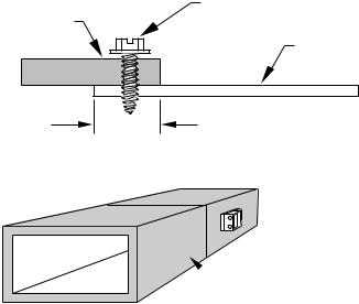
ROUND METAL DUCT WORK
1.Crimp end of branch duct.
2.Slip end of zone damper over end of duct work. Use self-tapping sheet metal screw to secure. (See Fig. 2.)
3.Properly seal joint using duct tape, mastic, or other approved method. Do not allow mastic to come in contact with actuator.
4.Insulate damper using 1-1/2 in. to 2-in. insulation. (Check your local codes.)
NOTE: All zone dampers and duct work must be properly supported according to local codes or SMACNA standards.
RECTANGULAR METAL DUCT WORK
1.Make connections using S-lock and drives. (See Fig. 2.)
2.Properly seal joint using duct tape, mastic, or other approved method. Do not allow mastic to come in contact with actuator.
MOUNTING
HUB
ACTUATOR
HOUSING
QUICK BLADE |
OPN COM CLS |
RELEASE |
|
BUTTON (RED) |
MOUNTING |
|
PLATE |
FIELD
INSTALLED
POWER WIRING
Fig. 1—Damper 24-vac Connections C02083
 S-LOCK
SUPPLY
AIR DUCT

 DRIVE
DRIVE  ZONE DAMPER
Fig. 2—Rectangular Metal Duct Work A92478
3.Insulate damper using 1-1/2 in. to 2-in. insulation. (Check your local codes.) (See Fig. 3.)
1 1/2 " TO 2" INSULATION
A95131
Fig. 3—Insulated Rectangular Metal Duct Work
ROUND FLEXIBLE DUCT WORK
1.Slip 1 end of flexible duct work over 1 end of zone damper. (See Fig. 4.)
FLEXIBLE |
ZONE |
DUCT |
DAMPER |
A95132
Fig 4—Round Flexible Duct Work
2.Secure flexible duct to zone damper using SMACNA or other approved method.
3.Properly seal joint using duct tape, mastic, or other approved method. Do not allow mastic to come in contact with actuator.
4.Insulate damper using 1-1/2 in. to 2-in. insulation. (Check your local codes.) (See Fig. 5.)
NOTE: All zone dampers and duct work must be properly supported according to local codes or SMACNA standards.
 1/2 ″ STEEL STRAP
A95133
Fig. 5—Insulated Round Duct Work
RECTANGULAR FIBROUS GLASS DUCT WORK
1.Insert 1 end of zone damper into 1 end of fibrous glass duct work approximately 2 to 3 in. (See Fig. 6.)
2.Screw field-supplied screws and tabs into zone damper.
3.Properly seal joint using duct tape, mastic, or other approved method. Do not allow mastic to come in contact with actuator.
4.Insulate damper using 1-1/2 in. to 2-in. insulation. (Check your local codes.) (See Fig. 7.)
3
FIBROUS
GLASS |
FIELD |
|
SUPPLIED |
||
DUCTWORK |
||
SCREWS |
||
|
||
|
ZONE |
|
|
DAMPER |
2″ TO 3″
A92480
Fig. 6—Rectangular Fibrous Glass Duct Work
 1 1/2 ″ TO 2″
INSULATION
A95134
Fig. 7—Insulated Rectangular Fibrous Glass Duct Work
Step 5—Install Barometric Bypass Damper
NOTE: The barometric bypass damper is a critical part of Carrier 3-Zone System for controlling noise at minimum airflow. A barometric bypass should be installed unless the duct work and indoor unit have been sized for use without a bypass.
The bypass should be installed according to local codes and SMACNA standards. Be sure bypass is properly supported.
For proper installation, refer to Installation Instructions packaged with barometric bypass.
Step 6—Install Leaving Air Temperature (LAT) Sensor
NOTE: The supplied LAT sensor must be installed for normal operation. Heat pump systems may use an optional HPT (heat pump temperature) sensor for added protection. These sensors protect the equipment when leaving air temperatures approach excessive levels.
Locate LAT sensor in main supply trunk after heating and cooling coil and before bypass damper and first branch. The LAT sensor is radiant shielded to prevent heat from affecting correct air temperature.
1.Drill a 1/4-in. hole at location in supply trunk where sensor will be installed.
2.Insert sensor in hole and use as a template to mark the 2 mounting holes.
3.Drill two 1/16-in. holes to accept No. 6 screws through pre-drilled holes in duct temperature sensor back plate.
4.Use 2 No. 6 sheet metal screws to mount duct temperature sensor to unit.
5.Connect sensor to 2-conductor wire using provided wire nuts. (See Fig. 9, 10, or 11 for connection to Carrier 3-Zone System.)
Step 7—Install Heat Pump Temperature (HPT) Sensor
The optional HPT sensor is recommended in all heat pump/fan coil installations. If an optional HPT sensor is not used, the 10K ohm resistor attached to the two HPT terminals on the board must be left in place. The HPT sensor measures the temperature of the air leaving the indoor coil. The sensor is to be installed downstream of the indoor coil but before the electric heaters. It can be installed
through the wall of the fan coil or may be located entirely inside the fan coil near the blower inlet. Anchor firmly in place with cable ties so that it cannot interfere with the blower wheel.
SYSTEM WIRING
Wiring the system is best done in four steps. Thermostats, Equipment, Dampers, and Remainder. The descriptions below and Table 1 will help you choose the correct wiring diagram for your system. Table 1 also shows the proper setting of dipswitches 9 and 10 for each diagram. Based on the equipment, 3-zone control, and thermostat type, select the appropriate wiring diagram. Terminal designations on all the thermostats are those of Carrier thermostats. Other brands may vary somewhat. Wiring diagrams and 3-Zone Control board layouts are located at the end of this Installation Instruction.
Table 1—Wiring Diagram Selection Chart
WIRING DIAGRAM |
EQUIPMENT |
3-ZONE |
STAT |
SWITCH 9 |
SWITCH 10 |
|
TYPE |
TYPE |
|||||
|
|
|
|
|||
|
|
|
|
|
|
|
Fig. 10 |
1-spd. AC, |
AC |
AC |
not present |
not present |
|
1-Stg. heat |
||||||
|
|
|
|
|
||
|
|
|
|
|
|
|
Fig. 11 |
1-spd. AC, |
HP/2S |
AC |
ON |
ON |
|
1 or 2-stg. heat |
||||||
|
|
|
|
|
||
Fig. 12 |
1-spd. HP, |
HP/2S |
HP |
OFF |
OFF |
|
1-stg. aux heat |
||||||
|
|
|
|
|
||
Fig. 13 |
1-spd. HP, |
HP/2S |
AC (2 ht) |
OFF |
ON |
|
1-stg. aux heat |
||||||
|
|
|
|
|
||
Fig. 14 |
2-spd. AC, |
HP/2S |
2S (AC) |
ON |
ON |
|
1 or 2-stg. heat |
||||||
|
|
|
|
|
||
Fig. 15 |
2-spd. HP, |
HP/2S |
2S (HP) |
OFF |
OFF |
|
1-stg. aux heat |
||||||
|
|
|
|
|
||
|
|
|
|
|
|
Fig. 8 - Shows the board layout for the AC Control. Fig. 9 - Shows the board layout for the HP/2S Control.
Fig. 10 - Shows the 3-Zone AC Control wiring. It supports only 1 stage cooling and 1 stage heating.
Fig. 11 - Shows that the 3-Zone HP/2S Control may be used in 1 stage cooling and 1 or 2 stage heating applications. For 2 stage heating, the stat may be a 2 stage heat AC stat or a HP stat converted to AC. (Carrier HP stats can be field converted to 2 stage heat AC stats.)
Fig. 12 - Shows the conventional HP system, using a HP stat. Only single stage auxiliary heat is supported for heat pump systems. Using the HP stat allows control of emergency heat directly from the stat.
Fig. 13 - Is also a HP system, but uses an AC stat with 2 stage heating instead of a HP stat. (Carrier HP stats can be field converted to 2 stage heat AC stats.) Here, emergency heat can only be selected by a switch on the 3-Zone Control.
Fig. 14 - Is a 2 speed AC system and may have 1 or 2 stages of heat. An HP/2S Control and a 2S stat set for AC operation must be used.
Fig. 15 - Is for a 2 speed HP. It requires an HP/2S Control and a 2S stat set for HP operation. Only single stage auxiliary heat is supported for heat pump systems.
Step 1—Wire Thermostats
All zone thermostats are wired identically, so only the Zone 1 thermostat is shown on the wiring diagrams. For physical location of connections on 3-Zone Control refer to Fig. 8 (AC Control) or 9 (HP Control).
Battery or power stealing thermostats may not require the C connection. Refer to thermostat Installation Instructions. Be careful not to cross zone numbers.
Step 2—Wire Equipment
Again, from the selected Fig. 10 through 13, make each connection as shown at the indoor and outdoor units and the 3-zone Control.
4
 Loading...