


58MXA 170 Series
Deluxe 4–Way Multipoise Fixed-Capacity
Direct Vent Condensing Gas Furnace
Visit www.carrier.com
Installation, Start-Up, and Operating Instructions
Sizes 040-140, Series 170
Condensate Trap Freeze Protection..................................11
Construct a Working Platform..........................................11
Horizontal Right (Supply-Air Discharge)
Applications ............................................................................11
Condensate Trap Location ................................................11
Condensate Trap Tubing...................................................11
Condensate Trap Field Drain Attachment........................13
Pressure Switch Tubing.....................................................13
Condensate Trap Freeze Protection..................................13
Construct a Working Platform..........................................13
LOCATION..................................................................................13
General....................................................................................13
A93040
NOTE: Read the entire instruction manual before starting the
installation.
This symbol → indicates a change since the last issue.
TABLE OF CONTENTS
SAFETY CONSIDERATIONS.....................................................2
INTRODUCTION..........................................................................3
CODES AND STANDARDS........................................................3
ELECTROSTATIC DISCHARGE (ESD) PRECAUTIONS........5
APPLICATIONS............................................................................6
General......................................................................................6
Upflow Applications.................................................................6
Condensate Trap Location (Factory-Shipped
Orientation)..........................................................................6
Condensate Trap Tubing (Factory-Shipped
Orientation)..........................................................................6
Condensate Trap Location (Alternate Upflow
Orientation)..........................................................................6
Condensate Trap Tubing (Alternate Upflow
Orientation)..........................................................................6
Condensate Trap Field Drain Attachment..........................7
Pressure Switch Tubing.......................................................7
Upper Collector Box and Inducer Housing
(Unused) Drain Connections...............................................7
Condensate Trap Freeze Protection....................................7
Downflow Applications............................................................8
Condensate Trap Location ..................................................8
Condensate Trap Tubing.....................................................8
Condensate Trap Field Drain Attachment..........................9
Pressure Switch Tubing.......................................................9
Condensate Trap Freeze Protection..................................10
Horizontal Left (Supply-Air Discharge)
Applications ............................................................................10
Condensate Trap Location ................................................10
Condensate Trap Tubing...................................................10
Condensate Trap Field Drain Attachments ......................11
Pressure Switch Tubing.....................................................11
Furnace Location Relative to Cooling
Equipment ...............................................................................14
Hazardous Locations...............................................................14
INSTALLATION.........................................................................15
Leveling Legs (If Desired).....................................................15
Installation in Upflow and Downflow
Applications ............................................................................15
Installation in Horizontal Applications..................................16
Air Ducts.................................................................................17
General Requirements .......................................................17
Ductwork Acoustical Treatment .......................................17
Supply Air Connections....................................................17
Return Air Connections.....................................................17
Filter Arrangement..................................................................18
Bottom Closure Panel.............................................................19
Gas Piping...............................................................................19
Electrical Connections............................................................20
115–v Wiring.....................................................................20
24–v Wiring.......................................................................22
Accessories ........................................................................22
Direct Venting.........................................................................22
Removal of Existing Furnaces from Common
Vent Systems.....................................................................22
Combustion-Air and Vent Piping .....................................22
Vent Extension Pipe..........................................................27
Concentric Vent and Combustion-Air
Termination Kit Installation..............................................29
Multiventing and Vent Terminations................................33
Condensate Drain....................................................................34
General...............................................................................34
Application.........................................................................34
Condensation Drain Protection .........................................35
START-UP, ADJUSTMENTS AND SAFETY CHECK...........35
General....................................................................................35
Prime Condensate Trap With Water......................................36
Purge Gas Lines......................................................................37
Sequence of Operation............................................................37
Heating Mode....................................................................37
Cooling Mode....................................................................40
Thermidistat Mode ............................................................40
Continuous Blower Mode .................................................41
58MXA
Manufacturer reserves the right to discontinue, or change at any time, specifications or designs without notice and without incurring obligations.
Book 1 4
Tab 6a 8a
PC 101 Catalog No. 535–80136 Printed in U.S.A. Form 58MXA-17SI Pg 1 9-04 Replaces: 58MXA-16SI
Heat Pump Mode...............................................................41
Component Test.................................................................41
Adjustments.............................................................................42
Set Gas Input Rate ............................................................42
Set Temperature Rise........................................................48
Adjust Blower Off Delay (Heat Mode)............................49
Set Thermostat Heat Anticipator ......................................49
Check Safety Controls............................................................49
Check Primary Limit Control ...........................................49
Check Pressure Switch......................................................49
Checklist..................................................................................50
AIRFLOW
FIRE, EXPLOSION, ELECTRICAL SHOCK AND
CARBON MONOXIDE POISONING HAZARD
Failure to follow this warning could result in electrical shock,
fire, personal injury, or death.
Improper installation, adjustment, alteration, service, maintenance, or use can cause carbon monoxide poisoning, explosion, fire, electrical shock, or other conditions which may
cause personal injury or property damage. Consult a qualified
installer, service agency, local gas supplier, or your distributor or branch for information or assistance. The qualified
installer or agency must use only factory-authorized and
listed kits or accessories when modifying this product.
Installing and servicing heating equipment can be hazardous due to
gas and electrical components. Only trained and qualified
personnel should install, repair, or service heating equipment.
Untrained personnel can perform basic maintenance functions
such as cleaning and replacing air filters. All other operations must
be performed by trained service personnel. When working on
heating equipment, observe precautions in literature, on tags, and
on labels attached to or shipped with unit and other safety
precautions that may apply.
These instructions cover the minimum requirements and conform
to existing national standards and safety codes. In some instances,
these instructions exceed certain local codes and ordinances,
especially those that may not have kept up with changing residential construction practices. We require these instructions as a
minimum for a safe installation.
Wear safety glasses and work gloves. Have a fire extinguisher
available during start-up and adjustment procedures and service
calls.
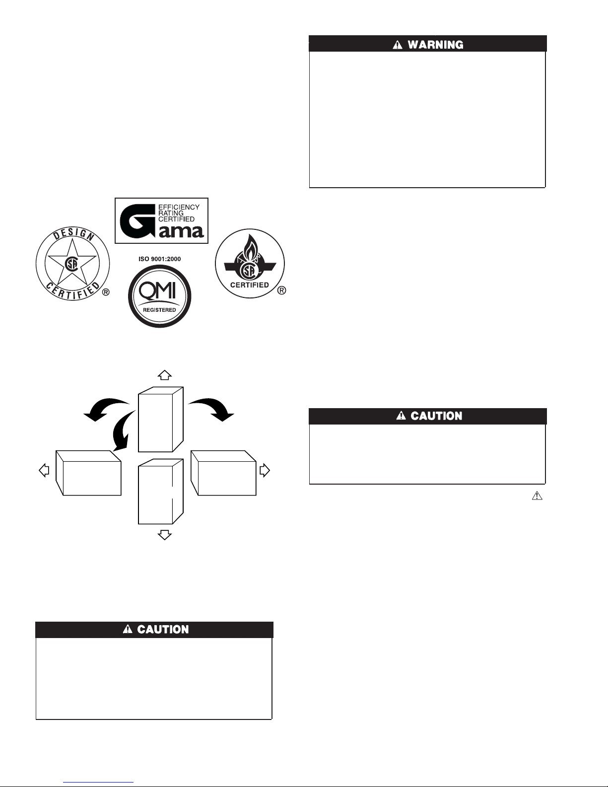
UPFLOW
HORIZONTAL
RIGHT
AIRFLOW
AIRFLOW
HORIZONTAL
LEFT
DOWNFLOW
AIRFLOW
Fig. 1—Multipoise Orientations
SAFETY CONSIDERATIONS
UNIT RELIABILITY HAZARD
Improper installation or misapplication of furnace may require excessive servicing or cause premature component
failure.
Application of this furnace should be indoors with special
attention given to vent sizing and material, gas input rate, air
temperature rise, unit leveling, and unit sizing.
A93041
CUT HAZARD
Failure to follow this caution may result in personal injury.
Sheet metal parts may have sharp edges or burrs. Use care and
wear appropriate protective clothing and gloves when handling parts.
Recognize safety information. This is the safety-alert symbol .
When you see this symbol on the unit and in instructions or
manuals, be alert to the potential for personal injury.
Understand these signal words: DANGER, WARNING, CAUTION, and NOTE. These words are used with the safety-alert
symbol. DANGER identifies the most serious hazards which will
result in severe personal injury or death. WARNING signifies
hazards which could result in personal injury or death. CAUTION
is used to identify unsafe practices which may result in minor
personal injury or product and property damage. NOTE is used to
highlight suggestions which will result in enhanced installation,
reliability, or operation.
The 58MXA Multipoise Condensing Gas-Fired Furnaces are
C.S.A. (formerly AGA and CGA) design-certified for natural and
propane gases (see furnace rating plate) and for installation in
alcoves, attics, basements, closets, utility rooms, crawlspaces, and
garages. The furnace is factory-shipped for use with natural gas. A
C.S.A. listed gas conversion kit is required to convert furnace for
use with propane gas.
See Fig. 3 for required clearances to combustibles.
Maintain a 1-in. clearance from combustible materials to supply air
ductwork for a distance of 36 inches horizontally from the furnace.
See NFPA 90B or local code for further requirements.
2

CODES AND STANDARDS
These furnaces SHALL NOT be installed directly on carpeting,
tile, or any other combustible material other than wood flooring. In
downflow installations, factory accessory floor base MUST be
used when installed on combustible materials and wood flooring.
Special base is not required when this furnace is installed on
manufacturer’s Coil Assembly Part No. CD5 or CK5, or when Coil
Box Part No. KCAKC is used.
The 58MXA 040 through 120 size units are C.S.A. design-certified
for use in manufactured (mobile) homes when factory accessory
conversion kit is used. The 140 size unit is NOT design-certified
for use in manufactured (mobile) homes. These furnaces are
suitable for installation in a structure built on site or a manufactured building completed at final site. The design of this furnace
line is NOT C.S.A. design-certified for installation in recreation
vehicles or outdoors.
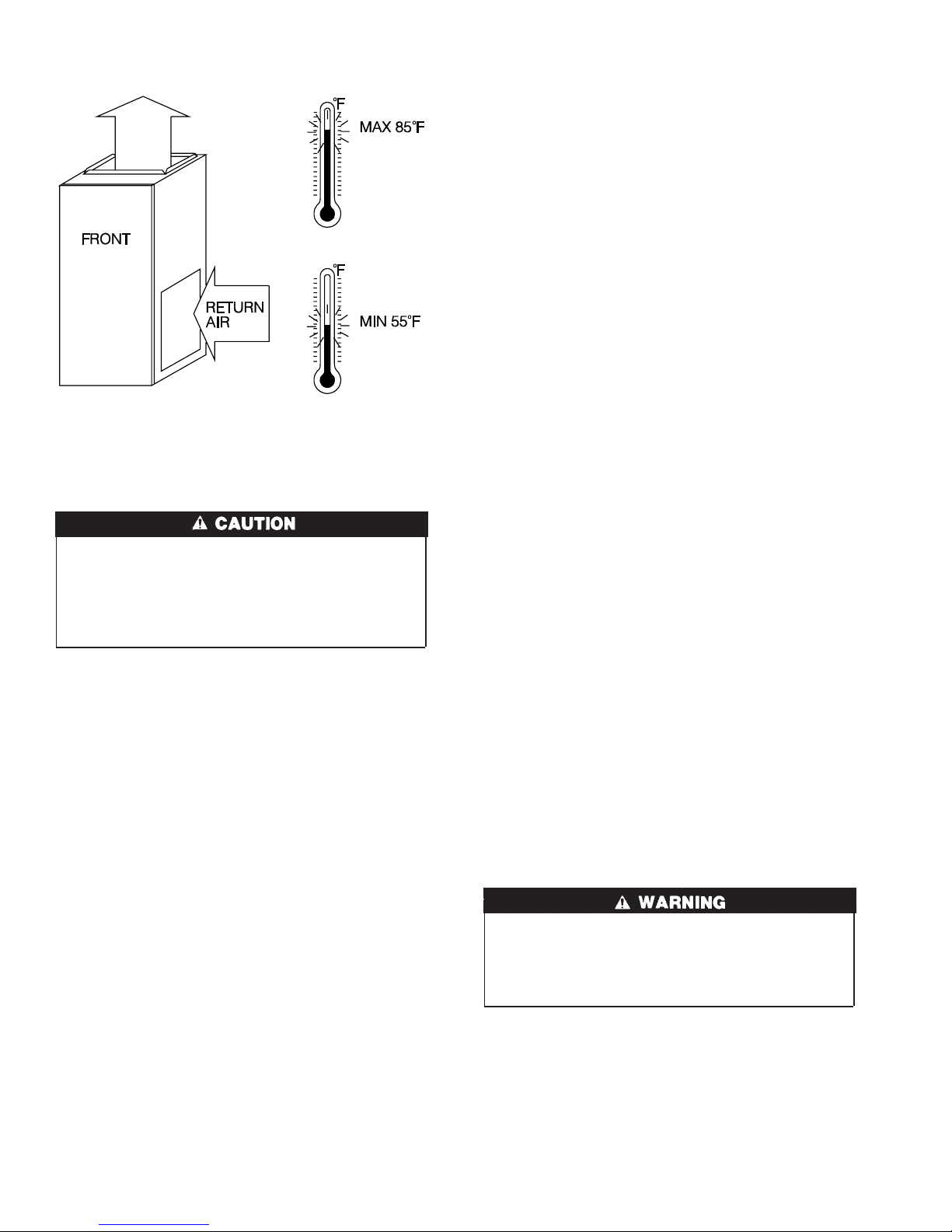
This furnace is designed for continuous return-air minimum
temperature of 60 °F db or intermittent operation down to 55°F db
such as when used with a night setback thermometer. Return-air
temperature must not exceed 85°F db. Failure to follow these
return air limits may affect reliability of heat exchangers, motors
and controls. (See Fig. 4.)
These furnaces are shipped with the drain and pressure tubes
connected for UPFLOW applications. Minor modifications are
required when used in DOWNFLOW, HORIZONTAL RIGHT, or
HORIZONTAL LEFT (supply-air discharge direction) applications as shown in Fig. 1. See details in Applications section.
This furnace must be installed with a direct-vent (combustion air
and flue gas) system and a factory accessory termination kit. In a
direct-vent system, all air for combustion is taken directly from the
outdoor atmosphere and flue gases are discharged to the outside
atmosphere. See furnace and factory accessory vent-air intake
termination kit instructions for proper installation.
These furnaces are shipped with the following materials to assist in
proper furnace installation. These materials are shipped in the main
blower compartment.
Installer Packet includes:
Installation, Startup, and Operating Instructions
Service and Maintenance Instructions
User’s Information Manual
Warranty Certificate
Loose Parts Bag includes: Quantity
Pressure tube extension 1
Collector Box or condensate trap extension tube 1
Inducer housing drain tube 1
1/2-in CPVC street elbow 2
Drain tube coupling 1
Drain tube coupling grommet 1
Vent and combustion-air pipe support 2
Condensate trap hole filler plug 3
Vent and combustion-air intake hole filler plug 2
Combustion-air pipe perforated disk assembly 1
Vent Pipe Extension 1*
* ONLY supplied with some furnaces.
For accessory installation details, refer to accessory installation
instructions.
Follow all national and local codes and standards in addition to
these instructions. The installation must comply with regulations
of the serving gas supplier, local building, heating, plumbing, and
other codes. In absence of local codes, the installation must
comply with the national codes listed below and all authorities
having jurisdiction.
In the United States and Canada, follow all codes and standards for
the following:
Step 1—Safety
• US: National Fuel Gas Code (NFGC) NFPA 54-2002/ANSI
Z223.1-2002 and the Installation Standards, Warm Air Heating
and Air Conditioning Systems ANSI/NFPA 90B
• CANADA: National Standard of Canada, Natural Gas and
Propane Installation Code (NSCNGPIC) CAN/CGA -B149,1
-and.2 M-00
Step 2—General Installation
• US: NFGC and the NFPA 90B. For copies, contact the National
Fire Protection Association Inc., Batterymarch Park, Quincy,
MA 02269; or for only the NFGC contact the American Gas
Association, 400 N. Capitol, N.W., Washington DC 20001
• CANADA: NSCNGPIC. For a copy, contact Standard Sales,
CSA International, 178 Rexdale Boulevard, Etobicoke (Toronto), Ontario, M9W 1R3, Canada.
Step 3—Combustion and Ventilation Air
• US: Section 5.3 of the NFGC, Air for Combustion and
Ventilation
• CANADA: Part 7 of the NSCNGPIC, Venting Systems and Air
Supply for Appliances
Step 4—Duct Systems
• US and CANADA: Air Conditioning Contractors Association
(ACCA) Manual D, Sheet Metal and Air Conditioning Contractors National Association (SMACNA), or American Society of Heating, Refrigeration, and Air Conditioning Engineers
(ASHRAE) 2001 Fundamentals Handbook Chapter 34.
Step 5—Acoustical Lining and Fibrous Glass Duct
• US and CANADA: current edition of SMACNA, NFPA 90B as
tested by UL Standard 181 for Class I Rigid Air Ducts
Step 6—Gas Piping and Gas Pipe Pressure Testing
• US: NFGC; chapters 2, 3, 4, and 9 and national plumbing codes
→
In the state of Massachusetts:
• This product must be installed by a licensed plumber or gas
fitter.
• When flexible connectors are used, the maximum length shall
not exceed 36 inches.
• When lever type gas shutoffs are used they shall not exceed 36
inches.
• CANADA: NSCNGPIC Parts 3, 4, 5, A, B, E, and H.
Step 7—Electrical Connections
• US: National Electrical Code (NEC) ANSI/NFPA 70-2002
• CANADA: Canadian Electrical Code CSA C22.1
INTRODUCTION
The model 58MXA 4-way multipoise, Gas-Fired, Category IV,
direct-vent condensing furnace is available in model sizes ranging
in input capacities of 40,000 to 138,000 Btuh.
3
"
8
⁄
"
16
"
16
⁄
13
⁄
5
"
8
⁄
5
7
39
1"
"
"
16
⁄
16
⁄
7
11
A02149
"
16
⁄
5
19"
"
22
4
⁄
OUTLET
1
"
16
⁄
26
15
"
2
⁄
26
1
28
A
AIRFLOW
2-IN. COMBUSTION-
"
16
⁄
9
TYP
TRAP LOCATION
"
16
⁄
CONDENSATE DRAIN
13
D
OUTLET
⁄2-IN. DIA
1
GAS CONN
AIR CONN
(DOWNFLOW &
OR ALTERNATE
-IN. DIA GAS CONN
2
⁄
1
HORIZONTAL RIGHT)
⁄8-IN. DIA
POWER CONN
7
1
⁄2-IN. DIA
THERMOSTAT ENTRY
"
2
⁄
1
30
2-IN. VENT CONN
"
16
⁄
11
22
SIDE INLET
"
4
⁄
1
18
1
" TYP
4
⁄
22
"
16
⁄
3
24
(UPFLOW)
BOTTOM INLET
HANGING
CONDENSATE
DRAIN LOCATION
FOR HORIZONTAL
DIMPLE LOCATORS
"
16
⁄
11
-in. rectangle.
-in. rectangle.
2
4
/
/
1
INLET
1
x 19
x 23
2
2
/
/
x 12-in. rectangle.
1
1
2
/
1
return air openings for airflow requirements above 1800 CFM at 0.5 W.C. ESP.
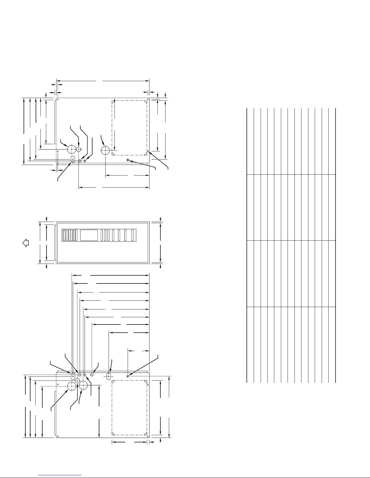
Dimensions (in.)
Fig. 2—Dimensional Drawing
040-08 17-1/2 15-7/8 16
040-12 17-1/2 15-7/8 16
060-08 17-1/2 15-7/8 16
060-12 17-1/2 15-7/8 16
060-16 17-1/2 15-7/8 16
080-12 17-1/2 15-7/8 16
080-16 17-1/2 15-7/8 16
080-20 21 19-3/8 19-1/2
100-16 21 19-3/8 19-1/2
100-20 21 19-3/8 19-1/2
120-20 24-1/2 22-7/8 23
UNIT SIZE A D E
140-20 24-1/2 22-7/8 23
"
16
⁄
13
⁄8-IN. DIA
7
CONDENSATE DRAIN
TRAP LOCATION
(DOWNFLOW &
HORIZONTAL LEFT)
"
16
⁄
15
"
4
⁄
1
26
"
2
⁄
1
26
"
16
⁄
24
5
22
-IN. COMBUSTION2
AIR CONN
POWER CONN
-IN. DIA
2
⁄
1
GAS CONN
-IN. VENT CONN
2
"
4
⁄
1
TYP
33
"
8
⁄
5
TYP
32
"
16
⁄
13
"
30
16
⁄
11
TYP
29
"
8
⁄
5
27
"
16
⁄
9
TYP
"
27
2
⁄
1
24
"
16
⁄
5
17
"
16
⁄
7
TYP
LOCATION
(ALTERNATE
UPFLOW)
SIDE INLET
"
2
⁄
1
TYP
14
9
CONDENSATE
DRAIN TRAP
⁄8-IN. DIA
ACCESSORY
POWER ENTRY
7
ENTRY
"
16
⁄
11
22
⁄2-IN. DIA THERMOSTAT
1
11
CONDENSATE
1
"
4
⁄
1
1
"
16
⁄
DRAIN LOCATION
(UPFLOW)
" TYP
" TYP
16
4
⁄
⁄
15
23
SIDE INLET
26
1" E
c. For 1600 CFM–22-in. round or 14
b. For 1200 CFM–20-in. round or 14
see flex duct manufacturer’s recommendations for equivalent diameters.
a. For 800 CFM–16-in. round or 14
2. Minimum return-air opening at furnace:
NOTES: 1. Minimum return-air openings at furnace, based on metal duct. If flex duct is used,
literature for specific use of single side inlets. The use of both side inlets, a
combination of 1 side and the bottom, or the bottom only will ensure adequate
d. For airflow requirements above 1800 CFM, see Air Delivery table in Product Data
4
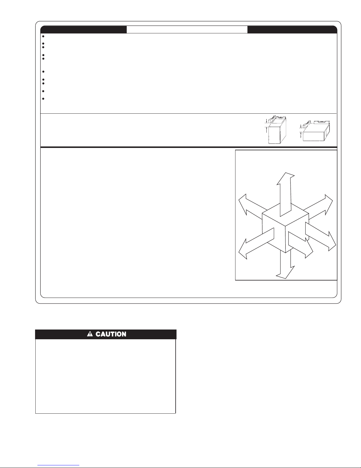
This forced air furnace is equipped for use with natural gas at altitudes 0 - 10,000 ft (0 - 3,050m), except 140 size furnaces are only approved for altitudes 0 - 7,000 ft.
INSTALLATION
(0 - 2,135m).
An accessory kit, supplied by the manufacturer, shall be used to convert to propane gas use or may be required for some natural gas applications.
This furnace is for indoor installation in a building constructed on site. This furnace may be installed in a manufactured (mobile) home when stated on rating plate and
using factory authorized kit..
This furnace may be installed on combustible flooring in alcove or closet at Minimum Inches Clearance To Combustible Construction as described below.
This furnace requires a special venting system. Refer to the installation instructions for parts list and method of installation. This furnace is for use with schedule-40 PVC,
PVC-DWV, CPVC, or ABS-DWV pipe, and must not be vented in common with other gas-fired appliances. Construction through which vent/air intake pipes may be
installed is maximum 24 inches (600 mm), minimum 3/4 inches (19 mm) thickness (including roofing materials).
Cette fournaise à air pulsé est équipée pour utilisation avec gaz naturel et altitudes comprises entre 0 - 3,050m (0 - 10,000 pi),excepté queles fournaises de 140 taille
sont pour altitudes comprises entre 0 - 2,135m (0 - 7,000pi).
Utiliser une trousse de conversion, fournie par le fabricant, pour passer au gaz propane ou pour certaines installations au gaz naturel.
Cette fournaise à air pulsé est pour installation à l´intérieur dans un bâtiment construit sur place. Cette fournaise à air pulse peut être installée dans une maison
préfabriquée (maison mobile) si prescrit par la plaque signalétique et si l' on utilise une trousse specifiée par le fabricant.
Cette fournaise peut être installée sur un plancher combustible dans un enfoncement ou un placard en observant les Dégagement Minimum En Pouces Avec
Éléments De Construction Combustibles.
Cette fournaise nécessite un système d´évacuation spécial. La méthode d´installation et la liste des pièces nécessaires figurent dans les instructions d´installation. Cette
fournaise doit s´utiliser avec la tuyauterie des nomenclatures 40 PVC, PVC-DWV, CPVC, ou ABS-DWV et elle ne peut pas être ventilée conjointment avec d´autres
appareils à gaz. Épaisseur de la construction au travers de laquelle il est possible de faire passer les tuyaux d'aération (admission/évacuation): 24 po (600 mm)
maximum, 3/4 po (19mm) minimum (y compris la toiture).
For upflow and downflow applications, furnace must be installed level, or pitched within 1/2" of level. For a
horizontal application, the furnace must be pitched minimum 1/4" to maximum of 1/2" forward for proper
drainage. See Installation Manual for IMPORTANT unit support details on horizontal applications.
Pour des applications de flux ascendant et descendant, la fournaise doit être installée de niveau ou inclinée à
pas plus de 1/2" du niveau. Pour une application horizontale, la fournaise doit être inclinée entre minimum
1/4" et maximum 1/2" du niveau pour le drainage approprié. En cas d´installation en position horizontale,
consulter les renseignements IMPORTANTS sur le support dans le manuel d´installation.
LEVEL (0") TO
1/2" MAX
UPFLOW OR
DOWNFLOW
FRONT
MIN 1/4" TO 1/2" MAX
FRONT
HORIZONTAL
MINIMUM INCHES CLEARANCE TO COMBUSTIBLE CONSTRUCTION
ALL POSITIONS:
Minimum front clearance for service 24 inches (610mm).
*
†
†
140 size furnaces require 1 inch back clearance to combustible materials.
DOWNFLOW POSITIONS:I
†
For installation on combustible floors only when installed on special base No. KGASB0201ALL,
Coil Assembly, Part No. CD5 or CK5, or Coil Casing, Part No. KCAKC.
HORIZONTAL POSITIONS::
Line contact is permissible only between lines formed by intersections of top and two sides of
furnace jacket, and building joists, studs, or framing.
§
Clearance shown is for air inlet and air outlet ends.
120 and 140 size furnaces require 1 inch bottom clearance to combustible materials.
Ø
DÉGAGEMENT MINIMUM EN POUCES AVEC ÉLÉMENTS DE CONSTRUCTION COMBUSTIBLES
POUR TOUS LES POSITIONS:U
Dégagement avant minimum de 610mm (24 po) pour l´entretien.
*
Pour les fournaises de 140 taille, 1 po (25mm) dégagement des matériaux combustibles est
†
†
requis au-arriere.
POUR LA POSITION COURANT DESCENDANT:
†
Pour l´installation sur le plancher combustible seulement quand on utilise la base spéciale, pièce
nº KGASB0201ALL, l
pièce nº KCAKC.
POUR LA POSITION HORIZONTALE:
Le contact n
deuxcôtés de la chemise de la fournaise, et des solives, des montants ou de la charpente du
bátiment.
La distance indiquée concerne l
§
d
´
air.
Ø
Pour les fournaises de 120 et 140 taille, 1 po (25mm) dégagement des matériaux combusitbles
est requis au-dessous.
´
ensemble serpentin, pièce nº CD5 ou CK5, ou le carter de serpentin,
´
est permis qúentre les lignes formées par les intersections du dessus et des
´
extrémité du tuyau d´arrivée d´air et l´extrémité du tuyau de sortie
→
ELECTROSTATIC DISCHARGE (ESD) PRECAUTIONS
UNIT DAMAGE HAZARD
→
Failure to follow this caution may damage furnace components.
Electrostatic discharge can affect electronic components.
Take precautions during furnace installation and servicing to
protect the furnace electronic control. Precautions will prevent electrostatic discharges from personnel and hand tools
which are held during the procedure. These precautions will
help to avoid exposing the control to electrostatic discharge
by putting the furnace, the control, and the person at the same
electrostatic potential.
1. Disconnect all power to the furnace. Multiple disconnects may
be required. DO NOT TOUCH THE CONTROL OR ANY
WIRE CONNECTED TO THE CONTROL PRIOR TO DISCHARGING YOUR BODY’S ELECTROSTATIC CHARGE
TO GROUND.
Fig. 3—Clearances to Combustibles
2. Firmly touch the clean, unpainted, metal surface of the furnace
chassis which is close to the control. Tools held in a person’s
hand during grounding will be satisfactorily discharged.
3. After touching the chassis, you may proceed to service the
control or connecting wires as long as you do nothing to
recharge your body with static electricity (for example; DO
NOT move or shuffle your feet, do not touch ungrounded
objects, etc.).
4. If you touch ungrounded objects (and recharge your body with
static electricity), firmly touch a clean, unpainted metal
surface of the furnace again before touching control or wires.
5. Use this procedure for installed and uninstalled (ungrounded)
furnaces.
6. Before removing a new control from its container, discharge
your body’s electrostatic charge to ground to protect the
control from damage. If the control is to be installed in a
furnace, follow items 1 through 4 before bringing the control
or yourself in contact with the furnace. Put all used and new
5
This furnace is approved for UPFLOW, DOWNFLOW and
HORIZONTAL installations.
Cette fournaise est approuvée pour l´installation HORIZONTALE
et la circulation d´air VERS LE HAUT et VERS LE BAS.
Clearance arrows
do not change with
furnace orientation.
†
†
0"
B
A
A
R
R
0"
§
Clearance in inches
Dégagement (po).
C
K
I
E
R
E
E
D
S
I
S
E
T
O
C
1"
Les fléches de dégagement
ne change pas avec
l
générateur d´air chaud.
TOP/PLENUM
DESSUS/CHAMBRE D´AIR
E
C
E
A
S
N
I
R
A
U
N
F
R
T
U
N
O
FO
T
R
N
F
A
V
A
L
È
F
R
O
A
N
V
T
A
N
T
3"
BOTTOM
0"
Ø
†
DESSOUS
Vent clearance to
combustibles 0".
0 (po) Dégagement
d´évent avec combustibles.
´
orientation de la
0"
E
D
S
I
S
E
T
O
C
S
E
R
N
V
I
T
R
C
E
T
I
E
328066-201 REV. B LIT TOP
§
E
*
N
24
MIN
A04110
A93042
Fig. 4—Return-Air Temperature
controls into containers before touching ungrounded objects.
7. An ESD service kit (available from commercial sources) may
also be used to prevent ESD damage.
PROPERTY DAMAGE
Failure to follow this caution may result in minor property
damage.
Local codes may require a drain pan under entire furnace and
condensate trap when a condensing furnace is used in an attic
application or over a finished ceiling.
APPLICATIONS
Step 1—General
Some assembly and modifications are required for furnaces
installed in any of the 4 applications shown in Fig. 1. All drain and
pressure tubes are connected as shown in Fig. 6. See appropriate
application instructions for these procedures.
Step 2—Upflow Applications
An upflow furnace application is where furnace blower is located
below combustion and controls section of furnace, and conditioned
air is discharged upwards.
CONDENSATE TRAP LOCATION (FACTORY-SHIPPED
ORIENTATION)
The condensate trap is factory installed in the blower shelf and
factory connected for UPFLOW applications. A factory-supplied
tube is used to extend the condensate trap drain connection to the
desired furnace side for field drain attachment. See Condensate
Trap Tubing (Factory-Shipped Orientation) section for drain tube
extension details. (See Fig. 5.)
CONDENSATE TRAP TUBING (FACTORY-SHIPPED
ORIENTATION)
NOTE: See Fig. 6 or tube routing label on main furnace door to
confirm location of these tubes.
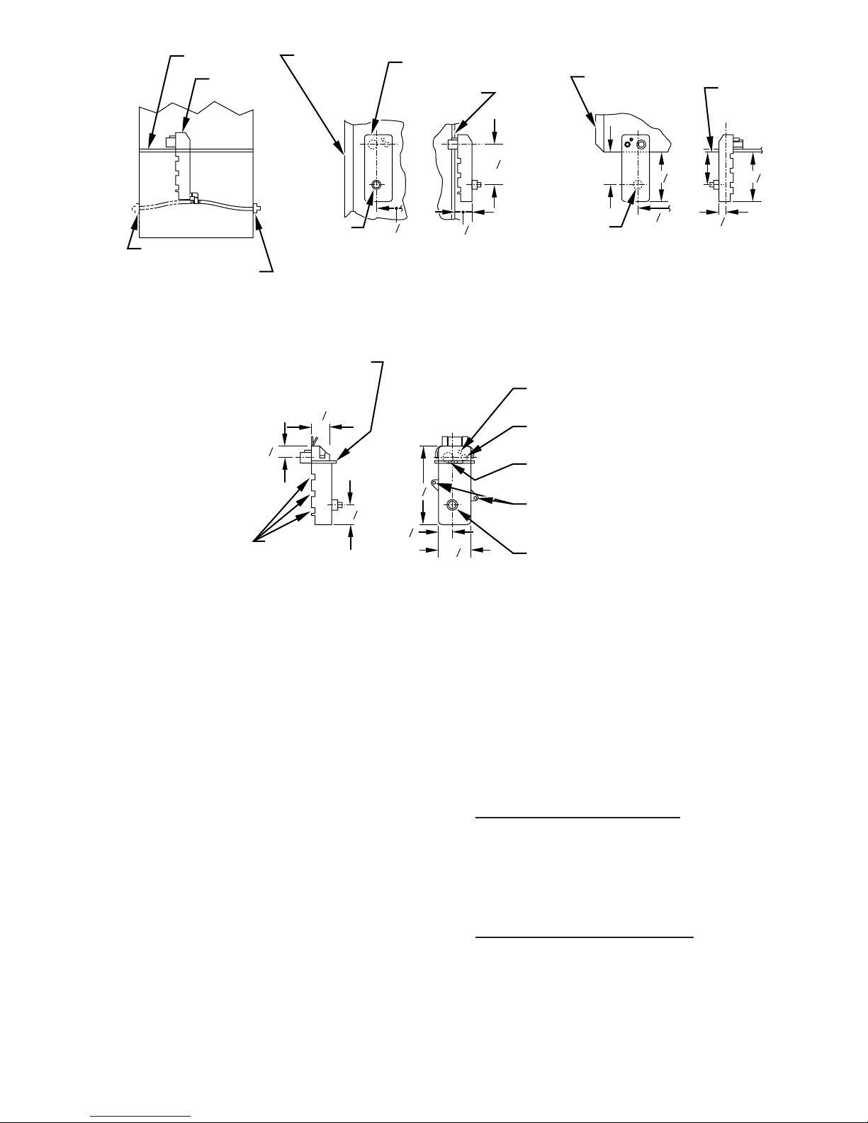
1. Collector Box Drain, Inducer Housing Drain, Relief Port, and
Pressure Switch Tubes.
These tubes should be factory attached to condensate trap and
pressure switch ready for use in UPFLOW applications. These
tubes can be identified by their connection location and also
by a color label on each tube. These tubes are identified as
follows: collector box drain tube (blue label), inducer housing
drain tube (violet label or molded), relief port tube (green
label), and pressure switch tube (pink label).
2. Condensate Trap Drain Tube
The condensate trap drain connection must be extended for
field attachment by doing the following:
a. Determine location of field drain connection. (See Fig. 2 or
6.)
NOTE: If internal filter or side Filter/Media Cabinet is used, drain
tube should be located to opposite side of casing from return duct
attachment to assist in filter removal.
b. Remove and discard casing drain hole plug button from
desired side.
c. Install drain tube coupling grommet (factory-supplied in
loose parts bag) in selected casing hole.
d. Slide drain tube coupling (factory-supplied in loose parts
bag) through grommet ensuring long end of coupling faces
blower.
e. Cement 2 factory-supplied 1/2-in. street CPVC elbows to
the rigid drain tube connection on the condensate trap. (See
Fig. 6.) These elbows must be cemented together and
cemented to condensate trap drain connection.
NOTE: Failure to use CPVC elbows may allow drain to kink and
prevent draining.
f. Connect larger diameter drain tube and clamp (factory-
supplied in loose parts bag) to condensate trap and clamp
securely.
g. Route tube to coupling and cut to appropriate length.
h. Attach tube to coupling and clamp securely.
CONDENSATE TRAP LOCATION (ALTERNATE UPFLOW
ORIENTATION)
An alternate location for the condensate trap is the left-hand side
of casing. (See Fig. 2 and 7.)
NOTE: If the alternate left-hand side of casing location is used,
the factory-connected drain and relief port tubes must be disconnected and modified for attachment. See Condensate Trap Tubing
(Alternate Upflow Orientation) section for tubing attachment.
To relocate condensate trap to the left-hand side, perform the
following:
1. Remove 3 tubes connected to condensate trap.
2. Remove trap from blower shelf by gently pushing tabs inward
and rotating trap.
3. Install casing hole filler cap (factory-supplied in loose parts
bag) into blower shelf hole where trap was removed.
CARBON MONOXIDE POISONING HAZARD
→
Failure to follow this warning could result in personal injury
or death.
Casing hole filler cap must be installed in blower shelf hole
when condensate trap is relocated.
4. Install condensate trap into left-hand side casing hole by
inserting tube connection stubs through casing hole and
rotating until tabs snap into locking position.
5. Fill unused condensate trap casing holes with plastic filler
caps (factory-supplied in loose parts bag).
CONDENSATE TRAP TUBING (ALTERNATE UPFLOW
ORIENTATION)
NOTE: See Fig. 7 or tube routing label on main furnace door to
confirm location of these tubes.
6
BLOWER SHELF
CONDENSATE
TRAP (INSIDE)
ALTERNATE DRAIN
TUBE LOCATION
CONDENSATE TRAP
DRAIN TUBE LOCATION
UPFLOW APPLICATIONS
FURNACE
DOOR
FIELD
DRAIN
CONN
EXTERNAL UPFLOW APPLICATIONS
SLOT FOR SCREW
HORIZONTAL
APPLICATION
(OPTIONAL)
1
1
2
3
4
WIRE TIE
GUIDES
(WHEN USED)
CONDENSATE
TRAP
FURNACE
SIDE
7
4
8
1
26
4
1
1
2
FURNACE
DOOR
FIELD
DRAIN
CONN
FURNACE
SIDE
4
3
5
4
4
1
26
4
3
5
3
4
SIDE VIEW FRONT VIEW END VIEW FRONT VIEW
DOWNFLOW AND ALTERNATE
1
7
8
3
1
4
7
8
1
2
4
1
⁄4 OD
COLLECTOR BOX TO
TRAP RELIEF PORT
1
⁄2 OD
INDUCER HOUSING
DRAIN CONNECTION
5
⁄8 OD
COLLECTOR BOX
DRAIN CONNECTION
SCREW HOLE FOR
UPFLOW OR DOWNFLOW APPLICATIONS
(OPTIONAL)
1
⁄2-IN. PVC OR CPVC
HORIZONTAL
APPLICATIONS
4
FRONT VIEW SIDE VIEW
Fig. 5—Condensate Trap
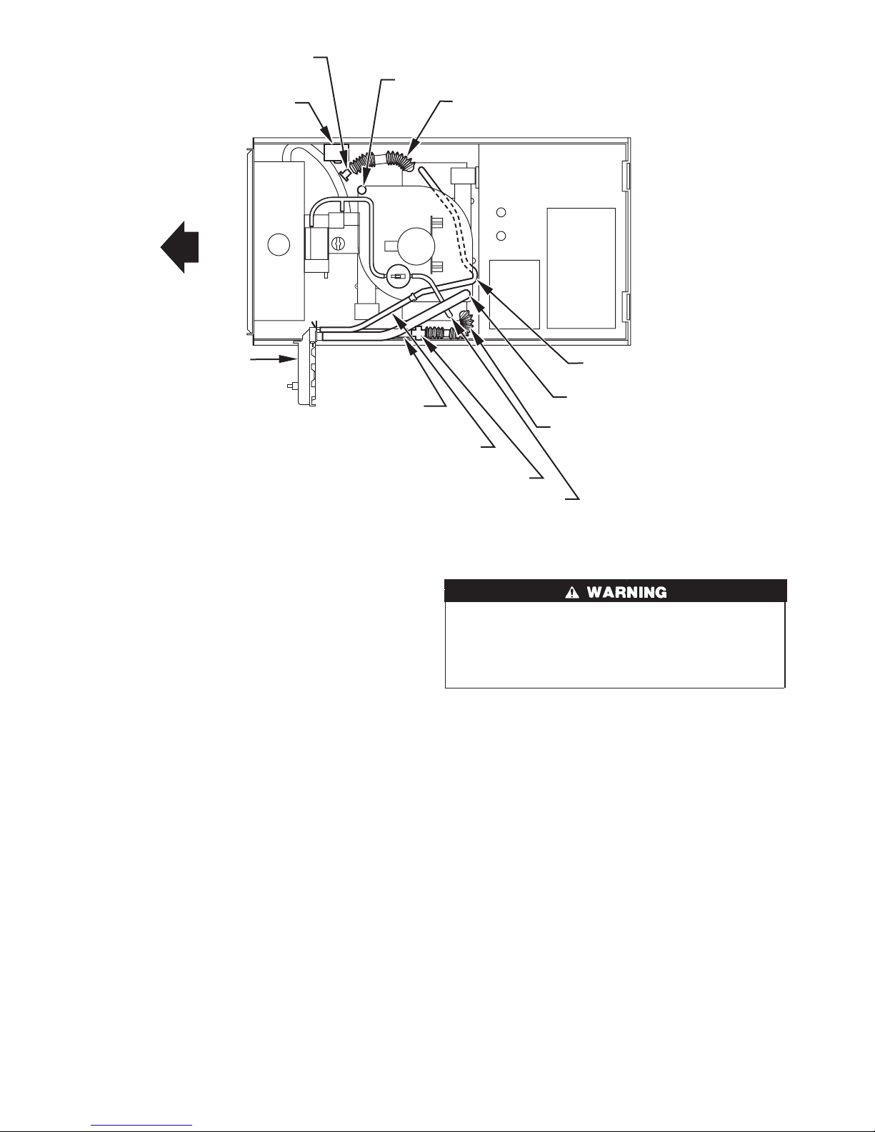
1. Collector Box Drain Tube
Connect collector box drain tube (blue label) to condensate
trap.
NOTE: On 17-1/2 in. wide furnaces ONLY, cut tube between
corrugated sections to prevent kinks from occurring.
2. Inducer Housing Drain Tube
a. Remove and discard LOWER (molded) inducer housing
drain tube which was previously connected to condensate
trap.
b. Use inducer housing drain extension tube (violet label and
factory-supplied in loose parts bag) to connect LOWER
inducer housing drain connection to the condensate trap.
c. Determine appropriate length, cut, and connect tube.
d. Clamp tube to prevent any condensate leakage.
3. Relief Port Tube
a. Connect relief port tube (green label) to condensate trap.
b. Extend this tube (if required) by splicing to small diameter
tube (factory-supplied in loose parts bag).
c. Determine appropriate length, cut, and connect tube.
CONDENSATE TRAP FIELD DRAIN ATTACHMENT
Refer to Condensate Drain section for recommendations and
procedures.
A93026
PRESSURE SWITCH TUBING
The LOWER collector box pressure tube (pink label) is factory
connected to the pressure switch and should not require any
modification.
NOTE: See Fig. 6 or 7 or tube routing label on main furnace door
to check for proper connections.
UPPER COLLECTOR BOX AND INDUCER HOUSING
(UNUSED) DRAIN CONNECTIONS
Upper Collector Box Drain Connection
Attached to the UPPER collector box drain connection is a
factory-installed corrugated, plugged tube (blue and white striped
label). This tube is plugged to prevent condensate leakage in this
application. Ensure this tube is plugged.
NOTE: See Fig. 6 or 7 or tube routing label on main furnace door
to check for proper connections.
Upper Inducer Housing Drain Connection
Attached to the UPPER (unused) inducer housing drain connection
is a cap and clamp. This cap is used to prevent condensate leakage
in this application. Ensure this connection is capped.
NOTE: See Fig. 6 or 7 or tube routing label on main furnace door
to check for proper connections.
CONDENSATE TRAP FREEZE PROTECTION
Refer to Condensate Drain Protection section for recommenda-
tions and procedures.
7
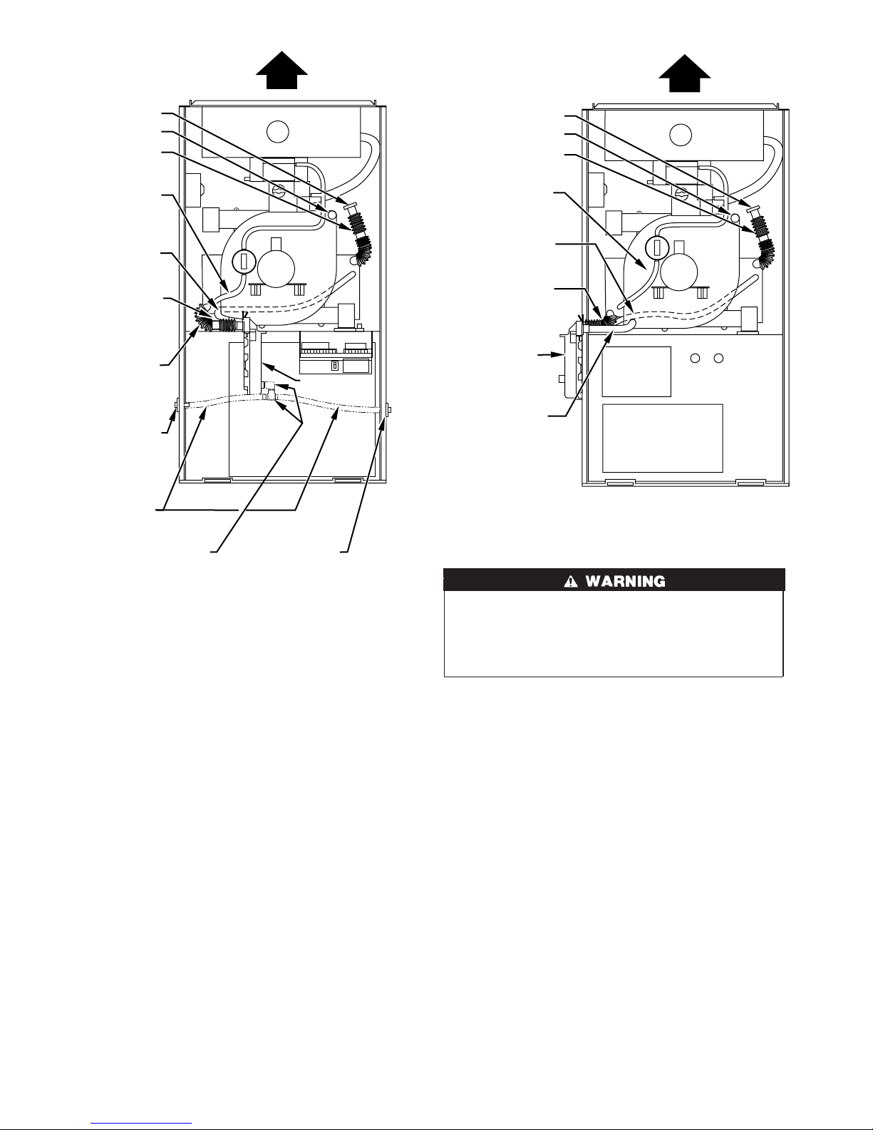
PLUG
CAP
COLLECTOR BOX
DRAIN TUBE (BLUE
& WHITE STRIPED)
COLLECTOR BOX
TUBE (PINK)
PLUG
CAP
COLLECTOR BOX
DRAIN TUBE (BLUE
& WHITE STRIPED)
COLLECTOR BOX
TUBE (PINK)
COLLECTOR BOX
TUBE (GREEN)
INDUCER HOUSING
(MOLDED) DRAIN
TUBE (BEHIND
COLLECTOR BOX
DRAIN TUBE)
COLLECTOR BOX
DRAIN TUBE (BLUE)
FIELD-INSTALLED
FACTORY-SUPPLIED
DRAIN TUBE
COUPLING (LEFT
DRAIN OPTION)
FIELD-INSTALLED
FACTORY-SUPPLIED
DRAIN TUBE
FIELD-INSTALLED
FACTORY-SUPPLIED
1
⁄2-IN. CPVC STREET
ELBOWS (2) FOR
LEFT DRAIN OPTION
FIELD-INSTALLED
FACTORY-SUPPLIED
COUPLING (RIGHT
CONDENSATE
TRAP
DRAIN TUBE
DRAIN OPTION)
A94163
Fig. 6—Factory-Shipped Upflow Tube
Configuration (Shown with Blower Access Panel
Removed)
Step 3—Downflow Applications
A downflow furnace application is where furnace blower is located
above combustion and controls section of furnace, and conditioned
air is discharged downwards.
CONDENSATE TRAP LOCATION
The condensate trap must be removed from the factory-installed
blower shelf location and relocated in selected application location
as shown in Fig. 2, 8, or 9.
To relocate condensate trap from the blower shelf to desired
location, perform the following:
1. Remove 3 tubes connected to condensate trap.
2. Remove trap from blower shelf by gently pushing tabs inward
and rotating trap.
3. Remove casing hole filler cap from casing hole. (See Fig. 2, 8,
or 9.)
4. Install casing hole filler cap into blower shelf hole where trap
was removed.
COLLECTOR BOX
TUBE (GREEN)
COLLECTOR BOX
DRAIN TUBE (BLUE)
CONDENSATE
TRAP
INDUCER
HOUSING
DRAIN TUBE
(VIOLET)
Fig. 7—Alternate Upflow Configuration and Trap
Location
CARBON MONOXIDE POISONING HAZARD
→
Failure to follow this warning could result in personal injury
or death.
Casing hole filler cap must be installed in blower shelf hole
when condensate trap is relocated.
5. Install condensate trap into desired casing hole by inserting
tube connection stubs through casing hole and rotating until
tabs snap into locking position.
CONDENSATE TRAP TUBING
NOTE: See Fig. 8 or 9 or tube routing label on main furnace door
to check for proper connections.
Relocate tubes as described below.
1. Collector Box Drain Tube
a. Remove factory-installed plug from LOWER collector box
drain tube (blue and white striped label).
b. Install removed clamp and plug into UPPER collector box
drain tube (blue label) which was connected to condensate
trap.
c. Connect LOWER collector box drain connection to con-
densate trap.
(1.) Condensate Trap Located on Left Side of Casing
(a.) Connect LOWER collector box drain tube (blue
and white striped label) to condensate trap. Tube
does not need to be cut.
(b.) Clamp tube to prevent any condensate leakage.
A94164
8
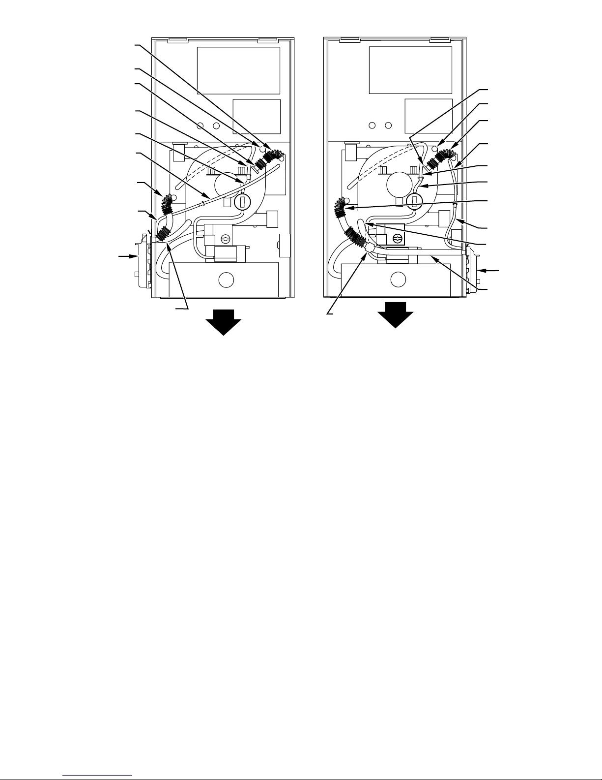
COLLECTOR BOX
DRAIN TUBE (BLUE)
CAP
PLUG
COLLECTOR BOX
TUBE (GREEN)
COLLECTOR BOX
EXTENSION TUBE
COLLECTOR BOX
TUBE (PINK)
COLLECTOR BOX
DRAIN TUBE (BLUE
& WHITE STRIPED)
COLLECTOR BOX
EXTENSION TUBE
CONDENSATE
TRAP
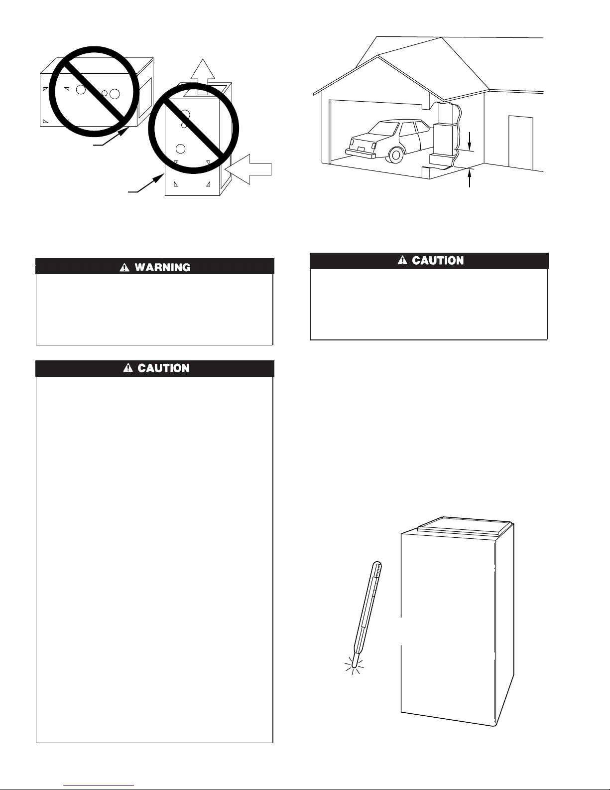
INDUCER HOUSING
DRAIN TUBE (VIOLET)
DRAIN TUBE
COUPLING
PLUG
CAP
COLLECTOR BOX
DRAIN TUBE (BLUE)
COLLECTOR BOX
TUBE (PINK)
COLLECTOR BOX
TUBE (GREEN)
COLLECTOR BOX
EXTENSION TUBE
COLLECTOR BOX
DRAIN TUBE (BLUE
& WHITE STRIPED)
COLLECTOR BOX
EXTENSION TUBE
INDUCER HOUSING
DRAIN TUBE
(VIOLET)
CONDENSATE
TRAP
COLLECTOR BOX
EXTENSION
DRAIN TUBE
A94165
Fig. 8—Downflow Tube Configuration (Left-Hand
Trap Installation)
(2.) Condensate Trap Located on Right Side of Casing
(a.) Install drain tube coupling (factory-supplied in
loose parts bag) into collector box drain tube
(blue and white striped label) which was previously plugged.
(b.) Connect larger diameter drain tube (factory-
supplied in loose parts bag) to drain tube coupling, extending collector box drain tube for
connection to condensate trap.
(c.) Route extended collector box drain tube directly
from collector box drain to condensate trap as
shown in Fig. 9.
(d.) Determine appropriate length and cut.
(e.) Connect to condensate trap.
(f.) Clamp tube to prevent any condensate leakage.
2. Inducer Housing Drain Tube
a. Remove factory-installed cap and clamp from LOWER
inducer housing drain connection.
b. Remove and discard UPPER (molded) inducer housing
drain tube which was previously connected to condensate
trap.
c. Install cap and clamp on UPPER inducer housing drain
connection where molded drain tube was removed.
d. Use inducer housing drain tube (violet label and factory-
supplied in loose parts bag) to connect LOWER inducer
housing drain connection to the condensate trap.
e. Connect inducer housing drain connection to condensate
trap.
(1.) Condensate Trap Located on Left Side of Casing
(a.) Determine appropriate length and cut.
A94166
Fig. 9—Downflow Tube Configuration (Right-Hand
Trap Installation)
(b.) Connect tube to condensate trap.
(c.) Clamp tube to prevent any condensate leakage.
(2.) Condensate Trap Located on Right Side of Casing
(a.) Route inducer housing drain tube (violet label)
directly from inducer housing to condensate trap
as shown in Fig. 9.
(b.) Determine appropriate length and cut.
(c.) Connect tube to condensate trap.
(d.) Clamp tube to prevent any condensate leakage.
3. Relief Port Tube
Refer to Pressure Switch Tubing section for connection procedure.
CONDENSATE TRAP FIELD DRAIN ATTACHMENT
Refer to Condensate Drain section for recommendations and
procedures.
PRESSURE SWITCH TUBING
One collector box pressure tube (pink label) is factory connected to
the pressure switch for use when furnace is installed in UPFLOW
applications. This tube MUST be disconnected and used for the
condensate trap relief port tube. The other collector box pressure
tube (green label) which was factory connected to the condensate
trap relief port connection MUST be connected to the pressure
switch in DOWNFLOW or HORIZONTAL RIGHT applications.
NOTE: See Fig. 8 or 9 or tube routing label on main furnace door
to check for proper connections.
1. Disconnect collector box pressure tube (pink label) attached to
pressure switch.
2. Extend collector box pressure tube (green label) which was
previously connected to condensate trap relief port connection
by splicing to small diameter tube (factory-supplied in loose
parts bag).
9
AUXILIARY "J" BOX
PLUG
CAP
COLLECTOR BOX
DRAIN TUBE
(BLUE AND WHITE STRIPED)
CONDENSATE
TRAP
COLLECTOR
BOX EXTENSION
DRAIN TUBE
COLLECTOR BOX
EXTENSION TUBE
RELOCATE TUBE BETWEEN BLOWER SHELF AND INDUCER HOUSING FOR
040, 060, AND 080 HEATING INPUT FURNACES
Fig. 10—Horizontal Left Tube Configuration
3. Connect collector box pressure tube (green label) to pressure
switch connection labeled COLLECTOR BOX.
4. Extend collector box pressure tube (pink label) which was
previously connected to pressure switch by splicing to remaining small diameter tube (factory-supplied in loose parts bag).
5. Route this extended tube (pink label) to condensate trap relief
port connection.
6. Determine appropriate length, cut, and connect tube.
7. Clamp tube to relief port connection.
CONDENSATE TRAP FREEZE PROTECTION
Refer to Condensate Drain Protection section for recommenda-
tions and procedures.
Step 4—Horizontal Left (Supply-Air Discharge)
Applications
A horizontal left furnace application is where furnace blower is
located to the right of combustion and controls section of furnace,
and conditioned air is discharged to the left.
CONDENSATE TRAP LOCATION
The condensate trap must be removed from the factory-installed
blower shelf location and relocated in selected application location
as shown in Fig. 2 or 10.
To relocate condensate trap from the blower shelf to desired
location, perform the following:
1. Remove 3 tubes connected to condensate trap.
2. Remove trap from blower shelf by gently pushing tabs inward
and rotating trap.
3. Install casing hole filler cap (factory-supplied in loose parts
bag) into blower shelf hole where trap was removed.
DRAIN TUBE COUPLING
COLLECTOR BOX TUBE (PINK)
CARBON MONOXIDE POISONING HAZARD
→
Failure to follow this warning could result in personal injury
or death.
Casing filler cap must be installed in blower shelf hole when
condensate trap is relocated.
4. Install condensate trap into left-hand side casing hole by
inserting tube connection stubs through casing hole and
rotating until tabs snap into locking position.
5. Fill unused condensate trap casing holes with plastic filler
caps (factory-supplied in loose parts bag).
CONDENSATE TRAP TUBING
NOTE: See Fig. 10 or tube routing label on main furnace door to
check for proper connections.
1. Collector Box Drain Tube
a. Install drain tube coupling (factory-supplied in loose parts
bag) into collector box drain tube (blue label) which was
previously connected to condensate trap.
b. Connect large diameter drain tube and clamp (factory-
supplied in loose parts bag) to drain tube coupling, extending collector box drain tube.
c. Route extended tube (blue label) to condensate trap and cut
to appropriate length.
d. Clamp tube to prevent any condensate leakage.
2. Inducer Housing Drain Tube
a. Remove and discard LOWER (molded) inducer housing
drain tube which was previously connected to condensate
trap.
10
COLLECTOR BOX
TUBE (GREEN)
INDUCER HOUSING
DRAIN TUBE (VIOLET)
COLLECTOR BOX
DRAIN TUBE (BLUE)
A00215
b. Use inducer housing drain extension tube (violet label and
factory-supplied in loose parts bag) to connect LOWER
inducer housing drain connection to the condensate trap.
c. Determine appropriate length, cut, and connect tube.
d. Clamp tube to prevent any condensate leakage.
3. Relief Port Tube
a. Extend collector box tube (green label) which was previ-
ously connected to the condensate trap by splicing to small
diameter tube (factory-supplied in loose parts bag).
b. Route extended collector box pressure tube to relief port
connection on the condensate trap.
c. Determine appropriate length, cut, and connect tube.
d. Clamp tube to prevent any condensate leakage.
CONDENSATE TRAP FIELD DRAIN ATTACHMENTS
Refer to Condensate Drain section for recommendations and
procedures.
PRESSURE SWITCH TUBING
The LOWER collector box pressure tube (pink label) is factory
connected to the pressure switch for use when furnace is installed
in UPFLOW applications. This tube MUST be disconnected,
extended, rerouted, and then reconnected to the pressure switch in
HORIZONTAL LEFT applications.
NOTE: See Fig. 10 or tube routing label on main furnace door to
check for proper connections.
Modify tube as described below.
1. Disconnect collector box pressure tube (pink label) attached to
pressure switch.
2. Use smaller diameter tube (factory-supplied in loose parts
bag) to extend tube disconnected in item 1.
3. Route extended tube:
a. Behind inducer housing.
b. Between blower shelf and inducer housing.
c. Behind inducer motor bracket.
d. Between inducer motor and pressure switch.
4. Determine appropriate length, cut, and reconnect tube to
pressure switch connection labeled COLLECTOR BOX.
CONDENSATE TRAP FREEZE PROTECTION
Refer to Condensate Drain Protection section for recommenda-
tions and procedures.
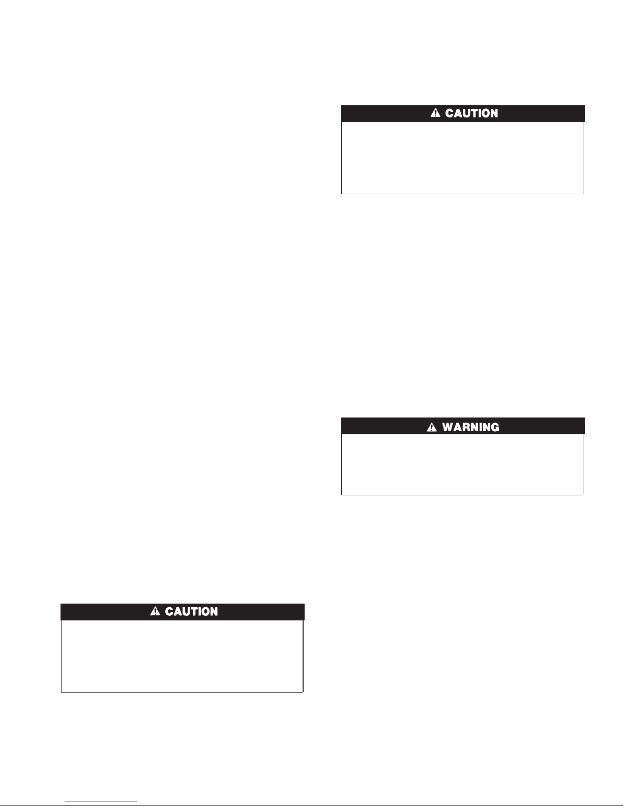
CONSTRUCT A WORKING PLATFORM
Construct working platform where all required furnace clearances
are met. (See Fig. 3 and 11.)
UNIT MAY NOT OPERATE
Failure to follow this caution may result in intermittent unit
operation.
The condensate trap MUST be installed below furnace. See
Fig. 5 for dimensions. The drain connection to condensate
trap must also be properly sloped to an open drain.
NOTE: Combustion-air and vent pipes are restricted to a minimum length of 5 ft. (See Table 7.)
NOTE: A 12-in. minimum offset pipe section is recommended
with short (5 to 8 ft) vent systems. This recommendation is to
reduce excessive condensate droplets from exiting the vent pipe.
(See Fig. 11 or 34.)
Step 5—Horizontal Right (Supply-Air Discharge)
Applications
A horizontal right furnace application is where furnace blower is
located to the left of combustion and controls section of furnace,
and conditioned air is discharged to the right.
PROPERTY DAMAGE
Failure to follow this caution may result in minor property
damage.
Local codes may require a drain pan under entire furnace and
condensate trap when a condensing furnace is used in attic
application or over a finished ceiling.
NOTE: In Canada, installations shall be in accordance with
current NSCNGPIC Installation Codes and/or local codes.
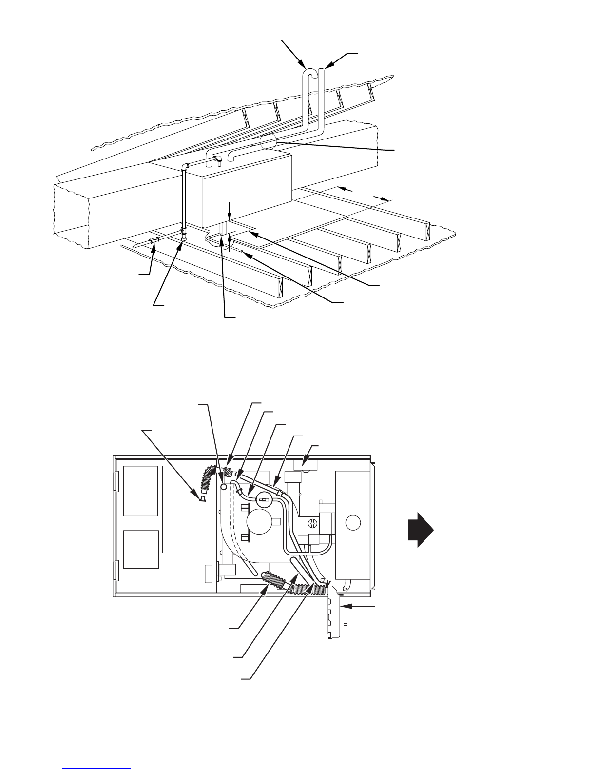
NOTE: The junction box (J-Box) MUST be relocated to opposite
side of furnace casing. (See Fig. 12.) See Electrical Connection
section for J-Box relocation.
CONDENSATE TRAP LOCATION
The condensate trap must be removed from the factory-installed
blower shelf location and relocated in selected application location
as shown in Fig. 2 or 12.
To relocate condensate trap from the blower shelf to desired
location, perform the following:
1. Remove 3 tubes connected to condensate trap.
2. Remove trap from blower shelf by gently pushing tabs inward
and rotating trap.
3. Install casing hole filler cap (factory-supplied in loose parts
bag) into blower shelf hole where trap was removed.
CARBON MONOXIDE POISONING HAZARD
→
Failure to follow this warning could result in personal injury
or death.
Casing hole filler cap must be installed in blower shelf when
condensate trap is relocated.
4. Install condensate trap into left-hand side casing hole by
inserting tube connection stubs through casing hole and
rotating until tabs snap into locking position.
5. Fill unused condensate trap casing holes with plastic filler
caps (factory-supplied in loose parts bag).
CONDENSATE TRAP TUBING
NOTE: See Fig. 12 or tube routing label on main furnace door to
check for proper connections.
1. Collector Box Drain Tube
a. Remove factory-installed plug from LOWER collector box
drain tube (blue and white striped label).
b. Install removed clamp and plug into UPPER collector box
drain tube (blue label) which was previously connected to
condensate trap.
c. Connect LOWER collector box drain tube (blue and white
striped label) to condensate trap. Tube does not need to be
cut.
d. Clamp tube to prevent any condensate leakage.
2. Inducer Housing Drain Tube
a. Remove factory-installed cap and clamp from LOWER
inducer housing drain connection.
11
MANUAL
SHUTOFF
GAS VALVE
COMBUSTION – AIR
SEDIMENT
TRAP
INTAKE
3
5
⁄
″
4
CONDENSATE
TRAP
VENT
30″ MIN
WORK AREA
DRAIN
A 12-IN. MIN HORIZONTAL PIPE
SECTION IS RECOMMENDED WITH
SHORT (5 TO 8 FT) VENT SYSTEMS
TO REDUCE EXCESSIVE
CONDENSATE DROPLETS FROM
EXITING THE VENT PIPE.
ACCESS OPENING
FOR TRAP
NOTE: LOCAL CODES MAY REQUIRE A DRAIN PAN UNDER THE
FURNACE AND CONDENSATE TRAP WHEN A CONDENSING
FURNACE IS INSTALLED ABOVE FINISHED CEILINGS.
Fig. 11—Attic Location and Working Platform
CAP
PLUG
COLLECTOR BOX DRAIN TUBE
(BLUE AND WHITE STRIPED)
A93031
COLLECTOR BOX DRAIN TUBE (BLUE)
COLLECTOR BOX TUBE (GREEN)
COLLECTOR BOX EXTENSION TUBE
COLLECTOR BOX TUBE (PINK)
AUXILARY “J” BOX RELOCATED HERE
CONDENSATE
TRAP
INDUCER HOUSING
DRAIN TUBE (VIOLET)
COLLECTOR BOX
EXTENSION TUBE
Fig. 12—Horizontal Right Tube Configuration
A00214
12
b. Remove and discard UPPER (molded) inducer housing
drain tube which was previously connected to condensate
trap.
c. Install cap and clamp on UPPER inducer housing drain
connection where molded drain tube was removed.
d. Use inducer housing drain extension tube (violet label and
factory-supplied in loose parts bag) to connect LOWER
inducer housing drain connection to condensate trap.
e. Determine appropriate length, cut, and connect tube to
condensate trap.
f. Clamp tube to prevent any condensate leakage.
3. Relief Port Tube
Refer to Pressure Switch Tubing section for connection
procedure.
CONDENSATE TRAP FIELD DRAIN ATTACHMENT
Refer to Condensate Drain section for recommendations and
procedures.
PRESSURE SWITCH TUBING
One collector box pressure tube (pink label) is factory connected to
the pressure switch for use when furnace is installed in UPFLOW
applications. This tube MUST be disconnected and used for the
condensate trap relief port tube. The other collector box pressure
tube (green label) which was factory connected to the condensate
trap relief port connection MUST be connected to the pressure
switch in DOWNFLOW or HORIZONTAL RIGHT applications.
NOTE: See Fig. 12 or tube routing label on main furnace door to
check for proper connections.
Relocate tubes as described below.
1. Disconnect collector box pressure tube (pink label) attached to
pressure switch.
2. Extend collector box pressure tube (green label) which was
previously connected to condensate trap relief port connection
by splicing to small diameter tube (factory-supplied in loose
parts bag).
3. Route extended collector box pressure tube behind inducer
motor bracket then between inducer motor and pressure
switch.
4. Connect collector box pressure tube (green label) to pressure
switch connection labeled COLLECTOR BOX.
5. Use remaining smaller diameter tube (factory-supplied in
loose parts bag) to extend collector box pressure tube (pink
label) which was previously connected to pressure switch.
6. Route this extended tube (pink label) to condensate trap relief
port connection.
7. Determine appropriate length, cut, and connect tube.
8. Clamp tube to relief port connection.
CONDENSATE TRAP FREEZE PROTECTION
Refer to Condensate Drain Protection section for recommenda-
tions and procedures.
CONSTRUCT A WORKING PLATFORM
Construct working platform where all required furnace clearances
are met. (See Fig. 3 and 11.)
UNIT MAY NOT OPERATE
Failure to follow this caution may result in intermittent unit
operation.
The condensate trap MUST be installed below furnace. See
Fig. 5 for dimensions. The drain connection to condensate
trap must also be properly sloped to an open drain.
NOTE: Combustion-air and vent pipes are restricted to a minimum length of 5 ft. (See Table 7.)
NOTE: A 12-in. minimum offset pipe section is recommended
with short (5 to 8 ft) vent systems. This recommendation is to
reduce excessive condensate droplets from exiting the vent pipe.
(See Fig. 11 or 34.)
LOCATION
Step 1—General
This furnace must
• be installed so the electrical components are protected from
water.
• not be installed directly on any combustible material other than
wood flooring (refer to SAFETY CONSIDERATIONS).
• be located so combustion-air and vent pipe maximum lengths
are not exceeded. Refer to Table 7.
• be located where available electric power and gas supplies meet
specifications on the furnace rating plate.
• be attached to an air distribution system and be located as close
to the center of the distribution system as possible. Refer to Air
Ducts section.
• be provided with ample space for servicing and cleaning.
Always comply with minimum fire protection clearances
shown on the furnace clearance-to-combustibles label.
This furnace may be located in a confined space without special
provisions for dilution or ventilation air.
When a furnace is installed so that supply ducts carry air circulated
by the furnace to areas outside the space containing the furnace,
the return air shall also be handled by ducts sealed to furnace
casing. The ducts terminate outside the space containing the
furnace to ensure there will not be a negative pressure condition
within equipment room or space.
LEVEL (0″)
TO
1
⁄2″ MAX
UPFLOW OR DOWNFLOW HORIZONTAL
FRONT
MIN
TO
1
⁄2″ MAX
1
⁄4″
FRONT
A02146
Fig. 13—Furnace Location for Proper Condensate
Drainage
NOTE: For upflow/downflow applications install furnace so that
it is level or pitched forward within 1/2-in. for proper furnace
operation. For horizontal applications pitch 1/4-in. minimum to
1/2-in. maximum forward to ensure proper condensate drainage
from secondary heat exchangers. (See Fig. 13.)
13
FRONT
BACK
B
A
C
K
FRONT
Fig. 14—Prohibit Installation on Back
FIRE HAZARD
→
Failure to follow this warning could result in fire of designed
unit operation injury, or death.
Do not install furnace on its back. Safety control operation
will be adversely affected. Never connect return-air ducts to
back of furnace. (See Fig. 14.)
→
UNIT DAMAGE HAZARD
This gas furnace may be used for construction heat provided
that:
-The furnace is permanently installed with all electrical
wiring, piping, venting and ducting installed according to
these installation instructions. A return air duct is provided,
sealed to the furnace casing, and terminated outside the space
containing the furnace. This prevents a negative pressure
condition as created by the circulating air blower, causing a
flame rollout and/or drawing combustion products into the
structure.
-The furnace is controlled by a thermostat. It may not be ″hot
wired″ to provide heat continuously to the structure without
thermostatic control.
-Clean outside air is provided for combustion. This is to
minimize the corrosive effects of adhesives, sealers and other
construction materials. It also prevents the entrainment of
drywall dust into combustion air, which can cause fouling and
plugging of furnace components.
-The temperature of the return air to the furnace is no less
than 55°F, with no evening setback or shutdown. The use of
the furnace while the structure is under construction is
deemed to be intermittent operation per our installation
instructions.
-The air temperature rise is within the rated rise range on the
furnace rating plate, and the firing rate has been set to the
nameplate value.
-The filters used to clean the circulating air during the
construction process must be either changed or thoroughly
cleaned prior to occupancy.
-The furnace, ductwork and filters are cleaned as necessary to
remove drywall dust and construction debris from all HVAC
system components after construction is completed.
A93043
18-IN. MINIMUM
TO BURNERS
Fig. 16—Installation in a Garage
UNIT DAMAGE HAZARD
Failure to follow this caution may result in minor property or
unit damage.
If furnace is installed in an unconditioned space where the
ambient temperatures may be 32°F or lower, freeze protection
measures must be taken. (See Fig. 15.)
Step 2—Furnace Location Relative to Cooling
Equipment
The cooling coil must be installed parallel with or on downstream
side of furnace to avoid condensation in heat exchanger. When
installed parallel with a furnace, dampers or other means used to
control flow of air shall be adequate to prevent chilled air from
entering furnace. If dampers are manually operated, they must be
equipped with a means to prevent operation of either unit, unless
damper is in full-heat or full-cool position.
Step 3—Hazardous Locations
32°F MINIMUM INSTALLED
AMBIENT OR FREEZE
PROTECTION REQUIRED
Fig. 15—Freeze Protection
14
A93044
A93058
FIRE, EXPLOSION, INJURY OR DEATH HAZARD
→
Improper location or inadequate protection could result in fire
or explosion.
When furnace is installed in a residential garage, it must be
installed so that burners and ignition sources are located a
minimum of 18 in. above floor. The furnace must be located
or protected to avoid physical damage by vehicles. When
furnace is installed in a public garage, airplane hangar, or
other building having a hazardous atmosphere, the furnace
must be installed in accordance with NFGC or NSCNGPIC.
(See Fig. 16.)
INSTALLATION
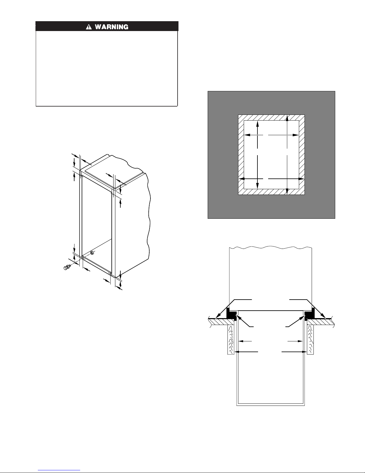
Step 1—Leveling Legs (If Desired)
When furnace is used in upflow position with side inlet(s), leveling
legs may be desired. (See Fig. 17.) Install field-supplied,
corrosion-resistant 5/16-in. machine bolts and nuts.
5
⁄16″
1. Determine application being installed from Table 1.
2. Construct hole in floor per dimensions specified in Table 1
and Fig. 18.
3. Construct plenum to dimensions specified in Table 1 and Fig.
18.
4. If downflow subbase (KGASB) is used, install as shown in
Fig. 19.
If Coil Assembly Part No. CD5 or CK5 or Coil Box Part No.
KCAKC is used, install as shown in Fig. 20.
A
PLENUM
OPENING
B
D
5
⁄16″
1 3⁄4″
3
⁄4″
1
5
⁄16″
5
⁄16″
3
1
⁄4″
1 3⁄4″
A89014
Fig. 17—Leveling Legs
NOTE: The maximum length of bolt should not exceed 1-1/2 in.
1. Position furnace on its back. Locate and drill a 5/16–in.
diameter hole in each bottom corner of furnace. (See Fig. 17.)
Holes in bottom closure panel may be used as guide locations.
2. For each hole, install nut on bolt and then install bolt and nut
in hole. (Install flat washer if desired.)
3. Install another nut on other side of furnace base. (Install flat
washer if desired.)
4. Adjust outside nut to provide desired height, and tighten inside
nut to secure arrangement.
NOTE: Bottom closure must be used when leveling legs are used.
See Bottom Closure Panel section.
Step 2—Installation in Upflow and Downflow
Applications
NOTE: For downflow applications, this furnace is approved for
use on combustible flooring when special base (available from
manufacturer) Part No. KGASB0201ALL is used. Special base is
not required when this furnace is installed on manufacturer’s Coil
Assembly Part No. CD5 or CK5, or Coil Box Part No. KCAKC is
used.
FLOOR
OPENING
C
A96283
Fig. 18—Floor and Plenum Opening Dimensions
FURNACE
(OR COIL CASING
WHEN USED)
COMBUSTIBLE
FLOORING
DOWNFLOW
SUBBASE
SHEET METAL
PLENUM
FLOOR
OPENING
A96285
Fig. 19—Furnace, Plenum, and Subbase Installed
on a Combustible Floor
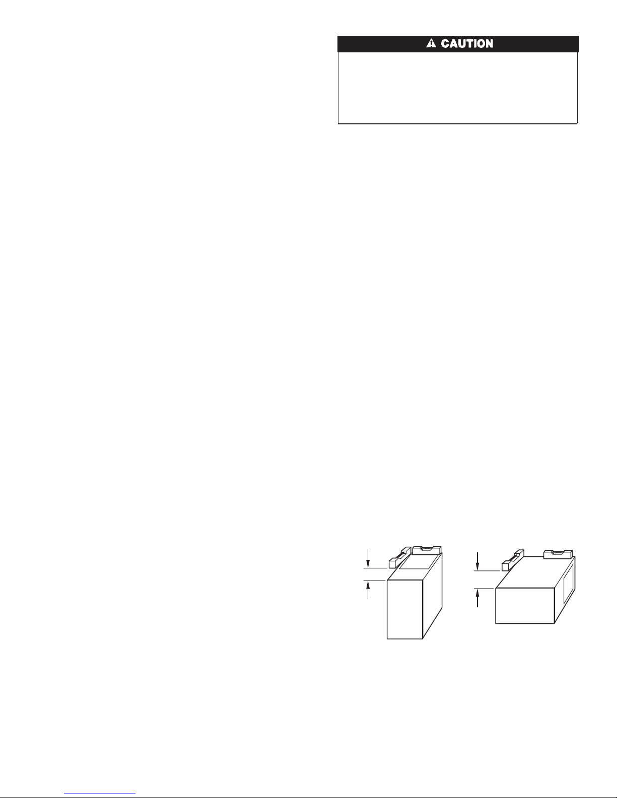
NOTE: Remove furnace perforated, discharge duct flanges when
they interfere with mating flanges on coil on downflow subbase.
To remove furnace perforated, discharge duct flange, use wide
15
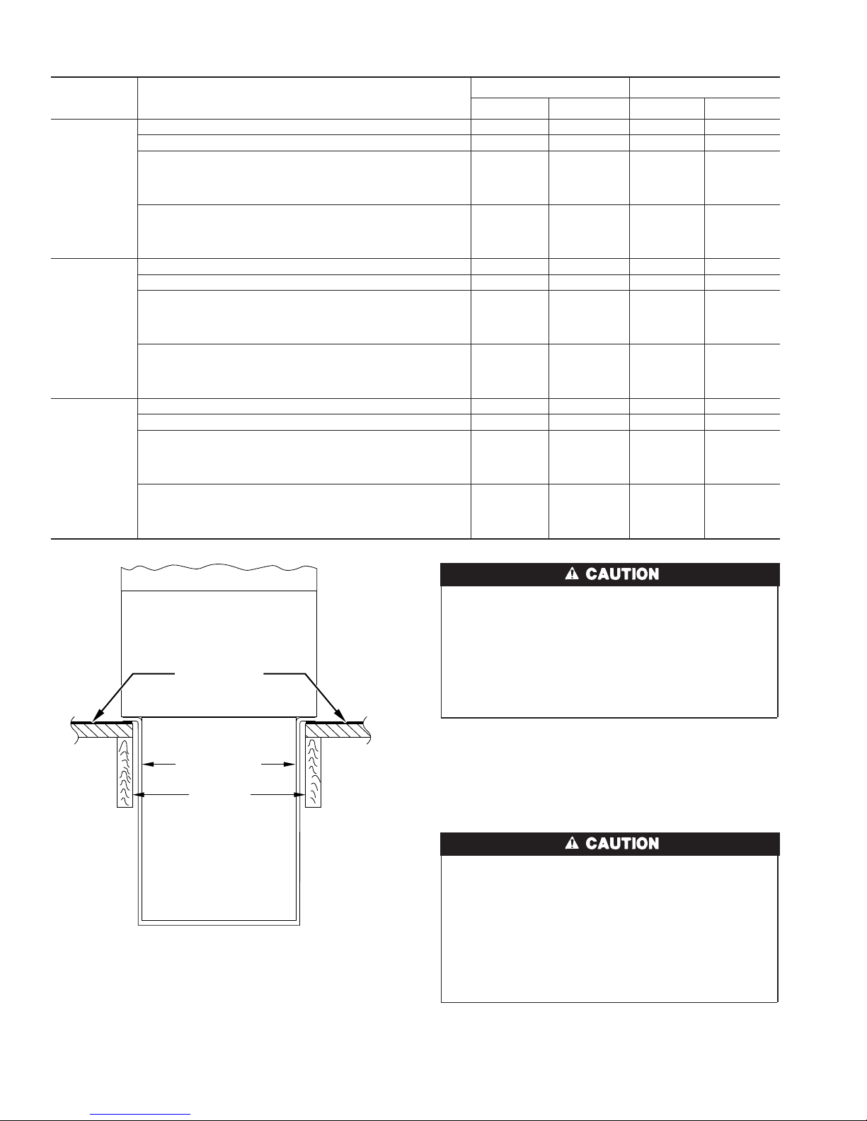
FURNACE
CASING
WIDTH
17-1/2
21
24-1/2
Table 1—Opening Dimensions (in.)
APPLICATION
Upflow Applications 16 24–1/8 16–5/8 24–3/4
Downflow Applications on Non-Combustible Flooring 15-7/8 19 16-1/2 19-5/8
Downflow Applications on Combustible Flooring Using
KGASB Subbase
Furnace with or without CD5 or CK5 Coil Assembly or
KCAKC Coil Box
Downflow Applications on Combustible Flooring NOT Using
KGASB Subbase
Furnace with or without CD5 or CK5 Coil Assembly or
KCAKC Coil Box
Upflow Applications 19-1/2 24-1/8 20-1/8 24-3/4
Downflow Applications on Non-Combustible Flooring 19-3/8 19 20 19-5/8
Downflow Applications on Combustible Flooring Using
KGASB Subbase
Furnace with or without CD5 or CK5 Coil Assembly or
KCAKC Coil Box
Downflow Applications on Combustible Flooring NOT Using
KGASB Subbase
Furnace with or without CD5 or CK5 Coil Assembly or
KCAKC Coil Box
Upflow Applications 23 24-1/8 23-5/8 24-3/4
Downflow Applications on Non-Combustible Flooring 22-7/8 19 23-1/2 19-5/8
Downflow Applications on Combustible Flooring Using
KGASB Subbase
Furnace with or without CD5 or CK5 Coil Assembly or
KCAKC Coil Box
Downflow Applications on Combustible Flooring NOT Using
KGASB Subbase
Furnace with or without CD5 or CK5 Coil Assembly or
KCAKC Coil Box
PLENUM OPENING FLOOR OPENING
ABCD
15-1/8 19 16-3/4 20-3/8
15-1/2 19 16-1/2 20
18-5/8 19 20-1/4 20-3/8
19 19 20 20
22-1/8 19 23-3/4 20-3/8
22-1/2 19 23-1/2 20
FURNACE
CD5 OR CK5
COIL ASSEMBLY
OR KCAKC
COIL BOX
COMBUSTIBLE
FLOORING
SHEET METAL
PLENUM
FLOOR
OPENING
A96284
Fig. 20—Furnace, Plenum, and Coil Assembly or
Coil Box Installed on a Combustible Floor
duct pliers or duct flange tool or hand seamers to bend flange back
and forth until it breaks off. Be careful of sharp edges. (See Fig.
21.)
UNIT MAY NOT OPERATE
→
Failure to follow this caution may result in intermittent unit
operation.
Do not bend duct flanges inward as shown in Fig. 21. This
will affect airflow across heat exchangers and may cause limit
cycling or premature heat exchanger failure. Remove duct
flange completely or bend it inward a minimum of 210° as
shown in Fig. 21.
NOTE: For 140 size unit when installed in downflow orientation,
cut the white jumper wire off between terminals PL1-7 and PL1-9.
Do not cut white jumper between terminals PL1-7 and PLI-11.
Refer to Fig. 30 for location of jumper. Cut jumper close to
connector and remove wire to avoid a short circuit.
Step 3—Installation in Horizontal Applications
UNIT MAY NOT OPERATE
Failure to follow this caution may result in intermittent unit
operation.
The entire length of furnace MUST be supported when
furnace is used in a horizontal position to ensure proper
draining. When suspended, bottom brace supports sides and
center blower shelf. When unit is supported from the ground,
blocks or pad should support sides and center blower shelf
area.
These furnaces can be installed horizontally in either horizontal
left or right discharge position. In a crawlspace, furnace can either
be hung from floor joist or installed on suitable blocks or pad.
Furnace can be suspended from each corner by hanger bolts and
16
 Loading...